ashrae 90.1 compliant - southern pipe & supply€¦ · 072 = 6 tons q = medium gas heat, 2...
TRANSCRIPT

P A C K A G E D G A S / e l e c t r i c
KGK-Series Rooftop Units
60 HZ
2 to 7.5 TonsNet Cooling Capacity − 23,600 to 90,000 Btuh
Gas Input Heat Capacity − 65,000 to 150,000 BtuhMODEL NUMBER IDENTIFICATION
K G A 060 S 4 B S 1 YBrand/Family
K = K Series Product Line
Unit Type G = Packaged Gas Heat w/ Electric Cooling
Major Design Sequence A = 1st Generation
B = 2nd Generation
Nominal Cooling Capacity - Tons 024 = 2 Tons
030 = 2.5 Tons 036 = 3 Tons 048 = 4 Tons 060 = 5 Tons 072 = 6 Tons
090 = 7.5 Tons
Cooling Efficiency S = Standard Efficiency
Refrigerant Type 4 = R-410A
Blower Type D = Direct Drive B = Belt Drive
Heating Type S = Standard Gas Heat, 1 stage M = Medium Gas Heat, 1 stage H = High Gas Heat, 2 Stage T = High Gas Heat, 1 Stage U = Medium Gas Heat, 2 Stage Q = Medium Gas Heat, 2 Stage, Low NOx W = Standard Gas Heat, 1 Stage, Low NOx Y = Medium Gas Heat, 1 Stage, Low NOx X = High Gas Heat, 2 Stage, Low NOx\ Z = High Gas Heat, 1 Stage, Low NOx
Minor Design Sequence 1 = 1st Revision 2 = 2nd Revision 3 = 3rd Revision
Voltage P = 208/230V−1 phase-60hz Y = 208/230V-3 phase-60hz G = 460V-3 phase-60hz J = 575V-3 phase-60hz
ASHRAE 90.1COMPLIANT
Bulletin No. KGA-024-090 (9/2014)P R O D U C T S P E C I F I C AT I O N S
K-Series Packaged Gas / Electric 2 to 7.5 Tons / Page 2
FEATURES AND BENEFITS
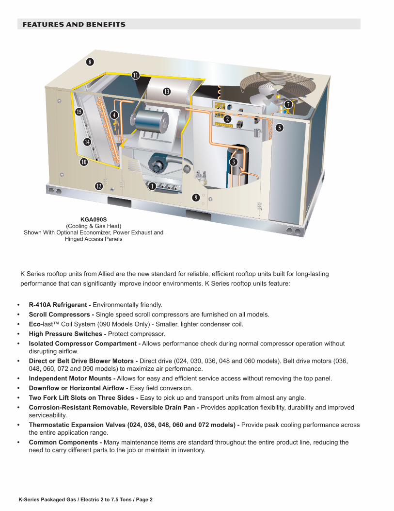
K Series rooftop units from Allied are the new standard for reliable, efficient rooftop units built for long-lasting performance that can significantly improve indoor environments. K Series rooftop units feature:
• R-410A Refrigerant - Environmentally friendly.• Scroll Compressors - Single speed scroll compressors are furnished on all models.• Eco-last™ Coil System (090 Models Only) - Smaller, lighter condenser coil.• High Pressure Switches - Protect compressor.• Isolated Compressor Compartment - Allows performance check during normal compressor operation without
disrupting airflow.• Direct or Belt Drive Blower Motors - Direct drive (024, 030, 036, 048 and 060 models). Belt drive motors (036,
048, 060, 072 and 090 models) to maximize air performance.• Independent Motor Mounts - Allows for easy and efficient service access without removing the top panel.• Downflow or Horizontal Airflow - Easy field conversion.• Two Fork Lift Slots on Three Sides - Easy to pick up and transport units from almost any angle.• Corrosion-Resistant Removable, Reversible Drain Pan - Provides application flexibility, durability and improved
serviceability.• Thermostatic Expansion Valves (024, 036, 048, 060 and 072 models) - Provide peak cooling performance across
the entire application range.• Common Components - Many maintenance items are standard throughout the entire product line, reducing the
need to carry different parts to the job or maintain in inventory.
KGA090S(Cooling & Gas Heat)
Shown With Optional Economizer, Power Exhaust andHinged Access Panels
B
C
D
E
F
H
I
J
K
L
M
N
O
P
K-Series Packaged Gas / Electric 2 to 7.5 Tons/ Page 3
FEATURES AND BENEFITS
APPROVALSAHRI Certified to AHRI Standard 210/240-2008 (2 thru 5 ton models) and AHRI Standard 340/360-2007 (6 and 7.5 ton models).ETL and CSA listed.Units are Certified by CSA.Components bonded for grounding to meet safety standards for servicing required by UL, ULC and National and Canadian Electrical Codes.All models are ASHRAE 90.1 compliant.ISO 9001 Registered Manufacturing Quality System.Models equipped with low NOx gas heat meet the California Nitrogen Oxides (NOx) Standards that apply in the South Coast Air Quality Management District and the San Francisco Bay Area Air Quality Management District.
WARRANTYLimited ten years aluminized heat exchanger, limited fifteen years optional stainless steel heat exchanger. Limited five years on compressors.Limited three years on the Eco-last™ Coil System.Limited five years Optional High Performance Economizers.Limited one year all other covered components.
HEATING SYSTEMAluminized steel inshot burners, direct spark ignition, electronic flame sensor, combustion air inducer, redundant automatic single or dual stage gas valve with manual shut-off.
Heat ExchangerTubular construction, aluminized steel, life cycle tested.Stainless Steel Heat Exchanger is required if mixed air temperature is below 45°F.
Electronic Pilot IgnitionElectronic spark igniter provides positive direct ignition of burners on each operating cycle. The system permits main gas valve to stay open only when the burners are proven to be lit. Should a loss of flame occur, the gas valve closes, shutting off the gas to the burners. Ignition module has LED to indicate status and aid in troubleshooting.Watchguard circuit on module automatically resets ignition controls after one hour of continuous thermostat demand after unit lockout, eliminating nuisance service calls. Ignition control is factory installed in the controls section.
B
C
Limit ControlsFactory installed, redundant limit controls with fixed temperature setting.Heat limit controls protect heat exchanger and other components from overheating.
Safety SwitchesFlame roll-out switch, flame sensor and combustion air inducer proving switch protect system operation.
Low NOx ModelsAll models are available in low NOx versions.
Required Selections
Gas Input Choice - Order one:• Standard Gas Heat (1 Stage)
65,000 Btuh (Not available for 090 models)
• Medium Gas Heat (1 Stage) 105,000 Btuh
• Medium Gas Heat (2 Stage) 73,500/105,000 Btuh
• High Gas Heat (1 Stage) 150,000 Btuh
• High Gas Heat (2 Stage) 105,000/150,000 Btuh
Standard or Low NOxSpecify standard gas heat or Low NOx option.
Options/Accessories
Factory InstalledStainless Steel Heat ExchangerRequired if mixed air temperature is below 45°F.
Combustion Air Intake ExtensionsRecommended for use with existing flue extension kits in areas where high snow areas can block intake air.
Low Temperature Vestibule HeaterElectric heater automatically controls minimum temperature in gas burner compartment when temperature is below -40°F. C.S.A. certified to allow operation of unit down to -60°F.
CONTENTSAccessory Dimensions . . . . . . . . . . . . . . . . . . . . . . . . . . .37Blower Data . . . . . . . . . . . . . . . . . . . . . . . . . . . . . . . . .21Blower Data - Direct Drive . . . . . . . . . . . . . . . . . . . . . . . . .18Dimensions . . . . . . . . . . . . . . . . . . . . . . . . . . . . . . . . .36Electrical Data . . . . . . . . . . . . . . . . . . . . . . . . . . . . . . .30Features And Benefits . . . . . . . . . . . . . . . . . . . . . . . . . . . 2High Altitude Derate . . . . . . . . . . . . . . . . . . . . . . . . . . . .15Model Number Identification . . . . . . . . . . . . . . . . . . . . . . . . 1Options / Accessories . . . . . . . . . . . . . . . . . . . . . . . . . . . . 9Outdoor Sound Data . . . . . . . . . . . . . . . . . . . . . . . . . . . .34Ratings . . . . . . . . . . . . . . . . . . . . . . . . . . . . . . . . . . .16Specifications - Belt Drive Blower. . . . . . . . . . . . . . . . . . . . . .14Specifications - Direct Drive Blower. . . . . . . . . . . . . . . . . . . . .12Specifications - Gas Heat . . . . . . . . . . . . . . . . . . . . . . . . . .15Unit Clearances . . . . . . . . . . . . . . . . . . . . . . . . . . . . . . .33Weight Data . . . . . . . . . . . . . . . . . . . . . . . . . . . . . . . . .35
K-Series Packaged Gas / Electric 2 to 7.5 Tons / Page 4
HEATING SYSTEM (continued)LPG/Propane KitsConversion kit to field change over units from Natural Gas to LPG/Propane.
Vertical Vent Extension KitUse to exhaust flue gases vertically above unit. Required when unit vent is too close to fresh air intakes per building codes. The vent kit also prevents ice formation on intake louvers.
COOLING SYSTEMDesigned to maximize sensible and latent cooling performance at design conditions.System can operate from 30°F to 125°F without any additional controls.
R-410A RefrigerantNon-chlorine, ozone friendly, R-410A.Unit is factory pre-charged with refrigerant. See Specifications Tables.
CompressorScroll compressors for high performance, reliability and quiet operation.Resiliently mounted on rubber grommets for quiet operation.
Compressor Crankcase Heater (Furnished on 072 Models Only)Protects against refrigerant migration that can occur during low ambient operation.
Thermal Expansion Valve (024 thru 072 Models)Assures optimal performance throughout the application range. Removable element head.
Refrigerant Metering Orifice (090 Models)Accurately meters refrigerant in system.Refrigerant control is accomplished by exact sizing of refrigerant metering orifice.
Filter/DrierHigh capacity filter/drier protects the system from dirt and moisture.
D
E
High Pressure SwitchProtects the compressor from overload conditions such as dirty condenser coils, blocked refrigerant flow, or loss of outdoor fan operation.
FreezestatProtects the evaporator coil from damaging ice build-up due to conditions such as low/no air flow, or low refrigerant charge.
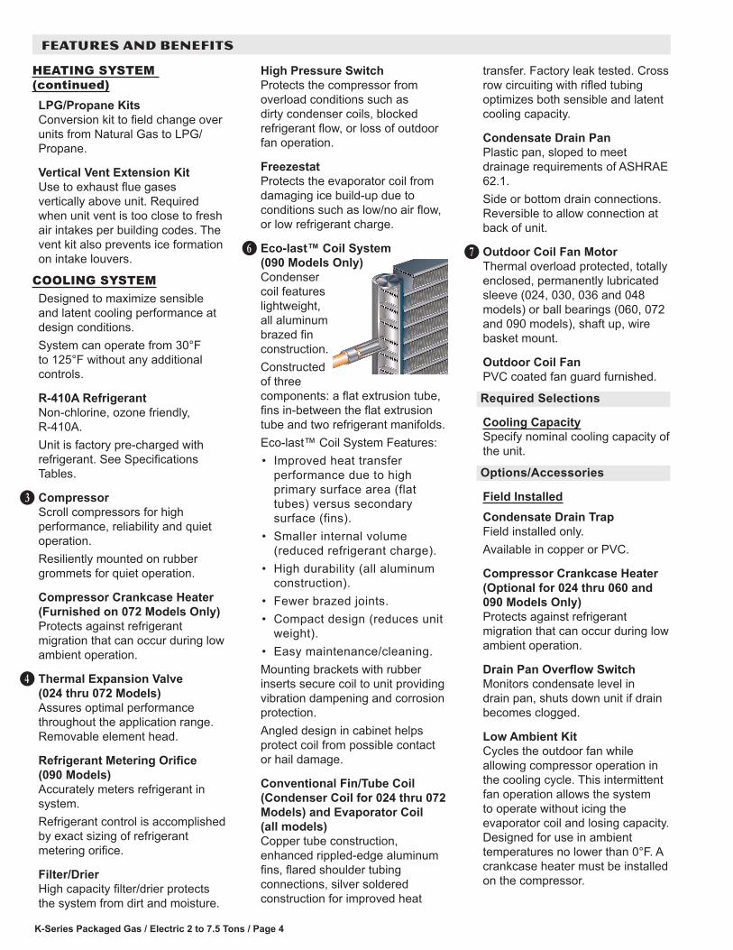
Eco-last™ Coil System (090 Models Only)Condenser coil features lightweight, all aluminum brazed fin construction. Constructed of three components: a flat extrusion tube, fins in-between the flat extrusion tube and two refrigerant manifolds. Eco-last™ Coil System Features:• Improved heat transfer
performance due to high primary surface area (flat tubes) versus secondary surface (fins).
• Smaller internal volume (reduced refrigerant charge).
• High durability (all aluminum construction).
• Fewer brazed joints.• Compact design (reduces unit
weight).• Easy maintenance/cleaning.Mounting brackets with rubber inserts secure coil to unit providing vibration dampening and corrosion protection.Angled design in cabinet helps protect coil from possible contact or hail damage.
Conventional Fin/Tube Coil (Condenser Coil for 024 thru 072 Models) and Evaporator Coil (all models)Copper tube construction, enhanced rippled-edge aluminum fins, flared shoulder tubing connections, silver soldered construction for improved heat
FG
transfer. Factory leak tested. Cross row circuiting with rifled tubing optimizes both sensible and latent cooling capacity.
Condensate Drain PanPlastic pan, sloped to meet drainage requirements of ASHRAE 62.1.Side or bottom drain connections. Reversible to allow connection at back of unit.
Outdoor Coil Fan MotorThermal overload protected, totally enclosed, permanently lubricated sleeve (024, 030, 036 and 048 models) or ball bearings (060, 072 and 090 models), shaft up, wire basket mount.
Outdoor Coil FanPVC coated fan guard furnished.
Required Selections
Cooling CapacitySpecify nominal cooling capacity of the unit.
Options/Accessories
Field InstalledCondensate Drain TrapField installed only.Available in copper or PVC.
Compressor Crankcase Heater (Optional for 024 thru 060 and 090 Models Only)Protects against refrigerant migration that can occur during low ambient operation.
Drain Pan Overflow SwitchMonitors condensate level in drain pan, shuts down unit if drain becomes clogged.
Low Ambient KitCycles the outdoor fan while allowing compressor operation in the cooling cycle. This intermittent fan operation allows the system to operate without icing the evaporator coil and losing capacity. Designed for use in ambient temperatures no lower than 0°F. A crankcase heater must be installed on the compressor.
H
FEATURES AND BENEFITS
K-Series Packaged Gas / Electric 2 to 7.5 Tons/ Page 5
CABINETConstructionHeavy-gauge steel panels and full perimeter heavy-gauge galvanized steel base rail provides structural integrity for transportation, handling, and installation. Base rails have rigging holes. Three sides of the base rail have fork slots.Raised edges around duct and power entry openings in the bottom of the unit provide additional protection against water entering the building.
Airflow ChoiceUnits are shipped in downflow (vertical) configuration, can be field converted to horizontal air flow configuration without the need of a kit.
Power/Gas EntryElectrical and gas lines can be brought through the unit base or through horizontal access knock-outs.Optional Bottom Gas Entry Kit is available.
Exterior PanelsConstructed of heavy-gauge, galvanized steel with a two-layer enamel paint finish.
InsulationAll panels adjacent to conditioned air are fully insulated with non-hygroscopic fiberglass insulation.Unit base is fully insulated. The insulation also serves as an air seal to the roof curb, eliminating the need to add a seal during installation.
Access PanelsAccess panels are provided for the economizer/filter section, heating/blower section, and the compressor/controls section.NOTE - Optional Economizers, Power Exhaust, Outdoor Air Dampers and Barometric Relief Dampers for 072/090 models include a filler panel for proper cabinet fit.
I
J
K
L
Options/Accessories
Factory InstalledCorrosion ProtectionA completely flexible immersed coating with an electro-deposited dry film process. (AST ElectroFin E-Coat) Meets Mil Spec MIL-P-53084, ASTM B117 Standard Method Salt Spray Testing.Indoor Corrosion Protection: - Coated coil - Painted blower housing - Painted baseOutdoor Corrosion Protection: - Coated coil - Painted base
Hinged Access PanelsLarge access panels are hinged and have quarter-turn latches for quick and easy access to maintenance areas (economizer / filter, compressor / controls, heating / blower).
Field InstalledCoil GuardsPainted, galvanized steel wire guards to protect outdoor coil. Not used with Hail Guards.
Hail GuardsConstructed of heavy gauge steel, painted to match cabinet, helps protect outdoor coils from hail damage. Not used with Coil Guards.
Bottom Gas Entry KitField installed piping kit to facilitate bottom gas entry.
M
CONTROLSUnit ControlAll control voltage is provided via a 24V (secondary) transformer with built-in circuit breaker protection.
Heat/Cool Staging - Capable of up to 2 heat / 2 cool staging with a third party DDC control system or thermostat.
Low Voltage Terminal Block - Provides screw terminal connections for thermostat or controller wiring.
Night Setback Mode - Saves energy by closing outdoor air dampers and operating supply fan on thermostat demand only.Options / Accessories
Field InstalledSmoke DetectorPhotoelectric type, installed in supply air section, return air section or both sections. Available with power board and single sensor (supply or return) or power board and two sensors (supply and return). Power board located in unit control compartment.
FEATURES AND BENEFITS

K-Series Packaged Gas / Electric 2 to 7.5 Tons / Page 6
FEATURES AND BENEFITS
BLOWERA wide selection of supply air blower options are available to meet a variety of air flow requirements.
MotorOverload protected, equipped with ball bearings (belt drive) or sleeve bearings (direct drive).Direct drive motors are offered on 024, 030, 036, 048 and 060 models.Belt drive motors are offered on 036, 048, 060, 072 and 090 models and are available in several different sizes to maximize air performance.
Supply Air BlowerForward curved blades, blower wheel is statically and dynamically balanced.All belt drive motors have adjustable pulley for speed change.
Ordering InformationSpecify direct drive or belt drive motorFor belt drive, specify motor horsepower and drive kit number when base unit is ordered.
Required Selections
Supply Air BlowerOrder one, belt drive or direct drive (See Blower Data Table for specifications).Order one drive kit, belt drive only, see Drive Kit Specifications Table.
N INDOOR AIR QUALITYAir FiltersDisposable 2 inch filters furnished as standard.
Options/Accessories
Field InstalledHigh Performance Air FiltersDisposable MERV 8 or MERV 13 (Minimum Efficiency Reporting Value based on ASHRAE 52.2) efficiency 2 inch pleated filters.
UVC Germicidal Lamps
Helps eliminate mold and bacterial growth on the evaporator and drain pans. Improves indoor air quality and maintains efficiency of system by reducing fouling of evaporator coil.
Indoor Air Quality (CO2) SensorMonitors CO2 levels adjusts economizer dampers as needed for Demand Control Ventilation.
ELECTRICALMarked & Color-Coded WiringAll electrical wiring is color-coded and marked to identify which components it is connecting.
Electrical PlugsPositive connection electrical plugs are used to connect common accessories or maintenance parts for easy removal or installation.
Required Selections
Voltage ChoiceSpecify when ordering base unit.
Options/Accessories
Factory or Field InstalledDisconnect Switch (80 Amp)Accessible from outside of unit, spring loaded weatherproof cover furnished. Main power to the unit is field connected to the disconnect which allows all power to be shut off for service. See Electrical tables for ordering information, page 30.
GFI Service Outlets (2)115V ground fault circuit interrupter (GFCI) type, non-powered, field-wired.
Field InstalledGFI Weatherproof CoverSingle-gang cover.Heavy-duty UV-resistant polycarbonate case construction.Hinged base cover with gasket.
K-Series Packaged Gas / Electric 2 to 7.5 Tons/ Page 7
ECONOMIZER OPTIONS
Factory or Field InstalledEconomizer (Standard and High Performance Common Features)Outdoor Air Hood is furnished.Factory installed Economizer can be ordered with two exhaust options:• Barometric Relief Dampers
and Exhaust Hood.• No Exhaust.Field installed Economizer includes Barometric Relief Dampers with Exhaust Hood.Barometric Relief Dampers allow relief of excess air, aluminum blade dampers prevent blow back and outdoor air infiltration during off cycle, bird screen furnished.Occupied/Unoccupied mode with field furnished setback thermostat.Demand Control Ventilation (DCV) ready using optional CO2 sensors.Mixed Air Sensor is furnished for field installation in the rooftop unit. Sensor is factory installed when Economizers are factory installed.Single sensible sensor is furnished with Economizer and enables economizer operation if the outdoor temperature is less than the setpoint of the control.Horizontal Economizer Conversion kit is available for field installation.
Standard Economizer Features (Not for Title 24)Gear-driven action, return air and outdoor air dampers, plug-in connections to unit, neoprene seals, 24-volt, fully-modulating spring return motor.
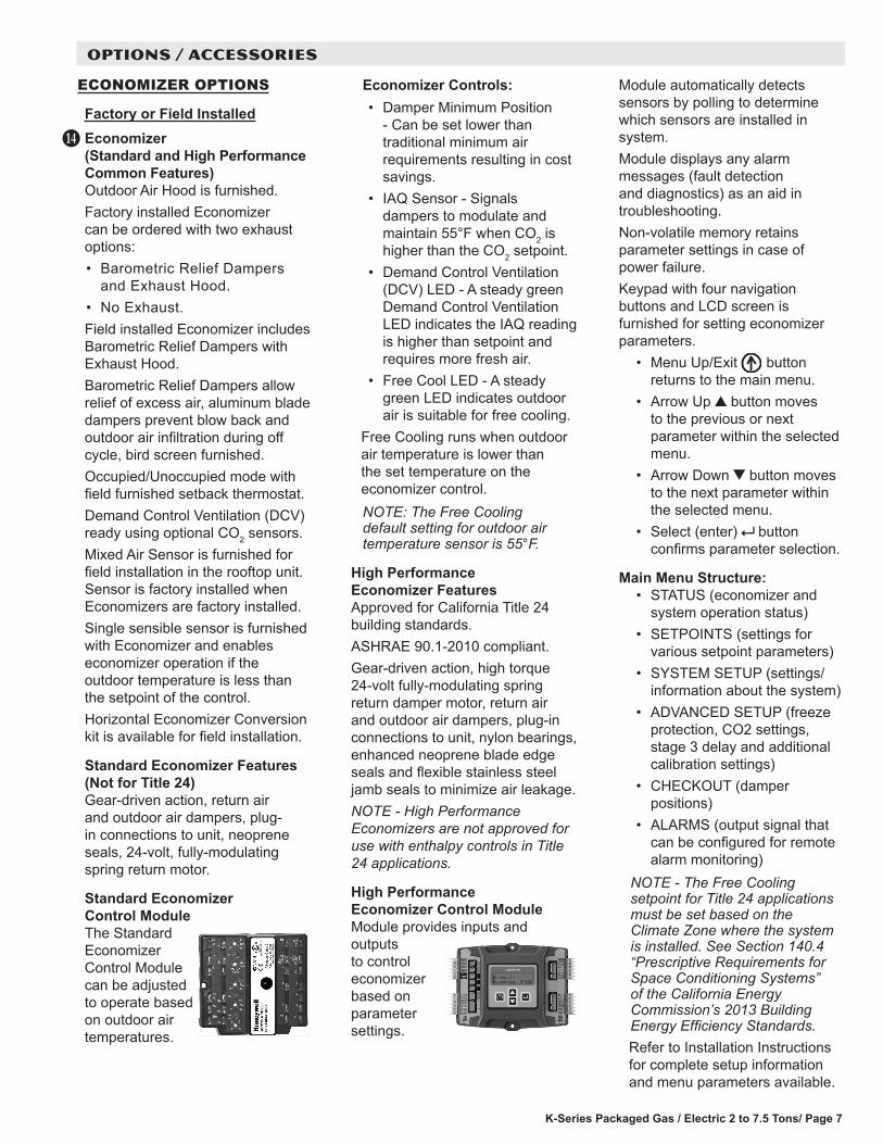
Standard Economizer Control ModuleThe Standard Economizer Control Module can be adjusted to operate based on outdoor air temperatures.
O
Economizer Controls:• Damper Minimum Position
- Can be set lower than traditional minimum air requirements resulting in cost savings.
• IAQ Sensor - Signals dampers to modulate and maintain 55°F when CO2 is higher than the CO2 setpoint.
• Demand Control Ventilation (DCV) LED - A steady green Demand Control Ventilation LED indicates the IAQ reading is higher than setpoint and requires more fresh air.
• Free Cool LED - A steady green LED indicates outdoor air is suitable for free cooling.
Free Cooling runs when outdoor air temperature is lower than the set temperature on the economizer control. NOTE: The Free Cooling default setting for outdoor air temperature sensor is 55°F.
High Performance Economizer FeaturesApproved for California Title 24 building standards.ASHRAE 90.1-2010 compliant.Gear-driven action, high torque 24-volt fully-modulating spring return damper motor, return air and outdoor air dampers, plug-in connections to unit, nylon bearings, enhanced neoprene blade edge seals and flexible stainless steel jamb seals to minimize air leakage.NOTE - High Performance Economizers are not approved for use with enthalpy controls in Title 24 applications.
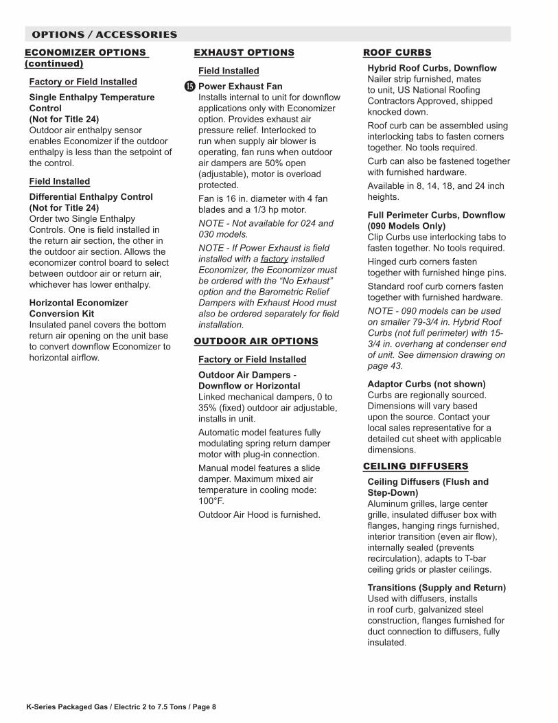
High Performance Economizer Control ModuleModule provides inputs and outputs to control economizer based on parameter settings.
Module automatically detects sensors by polling to determine which sensors are installed in system.Module displays any alarm messages (fault detection and diagnostics) as an aid in troubleshooting.Non-volatile memory retains parameter settings in case of power failure.Keypad with four navigation buttons and LCD screen is furnished for setting economizer parameters.
• Menu Up/Exit button returns to the main menu.
• Arrow Up button moves to the previous or next parameter within the selected menu.
• Arrow Down button moves to the next parameter within the selected menu.
• Select (enter) button confirms parameter selection.
Main Menu Structure:• STATUS (economizer and
system operation status)• SETPOINTS (settings for
various setpoint parameters)• SYSTEM SETUP (settings/
information about the system)• ADVANCED SETUP (freeze
protection, CO2 settings, stage 3 delay and additional calibration settings)
• CHECKOUT (damper positions)
• ALARMS (output signal that can be configured for remote alarm monitoring)
NOTE - The Free Cooling setpoint for Title 24 applications must be set based on the Climate Zone where the system is installed. See Section 140.4 “Prescriptive Requirements for Space Conditioning Systems” of the California Energy Commission’s 2013 Building Energy Efficiency Standards.Refer to Installation Instructions for complete setup information and menu parameters available.
OPTIONS / ACCESSORIES
K-Series Packaged Gas / Electric 2 to 7.5 Tons / Page 8
ECONOMIZER OPTIONS (continued)
Factory or Field InstalledSingle Enthalpy Temperature Control (Not for Title 24)Outdoor air enthalpy sensor enables Economizer if the outdoor enthalpy is less than the setpoint of the control.
Field InstalledDifferential Enthalpy Control (Not for Title 24)Order two Single Enthalpy Controls. One is field installed in the return air section, the other in the outdoor air section. Allows the economizer control board to select between outdoor air or return air, whichever has lower enthalpy.
Horizontal Economizer Conversion KitInsulated panel covers the bottom return air opening on the unit base to convert downflow Economizer to horizontal airflow.
OPTIONS / ACCESSORIES
EXHAUST OPTIONS
Field InstalledPower Exhaust FanInstalls internal to unit for downflow applications only with Economizer option. Provides exhaust air pressure relief. Interlocked to run when supply air blower is operating, fan runs when outdoor air dampers are 50% open (adjustable), motor is overload protected.Fan is 16 in. diameter with 4 fan blades and a 1/3 hp motor.NOTE - Not available for 024 and 030 models.NOTE - If Power Exhaust is field installed with a factory installed Economizer, the Economizer must be ordered with the “No Exhaust” option and the Barometric Relief Dampers with Exhaust Hood must also be ordered separately for field installation.
OUTDOOR AIR OPTIONS
Factory or Field InstalledOutdoor Air Dampers - Downflow or Horizontal Linked mechanical dampers, 0 to 35% (fixed) outdoor air adjustable, installs in unit.Automatic model features fully modulating spring return damper motor with plug-in connection.Manual model features a slide damper. Maximum mixed air temperature in cooling mode: 100°F.Outdoor Air Hood is furnished.
P
ROOF CURBSHybrid Roof Curbs, DownflowNailer strip furnished, mates to unit, US National Roofing Contractors Approved, shipped knocked down.Roof curb can be assembled using interlocking tabs to fasten corners together. No tools required.Curb can also be fastened together with furnished hardware.Available in 8, 14, 18, and 24 inch heights.
Full Perimeter Curbs, Downflow (090 Models Only)Clip Curbs use interlocking tabs to fasten together. No tools required.Hinged curb corners fasten together with furnished hinge pins.Standard roof curb corners fasten together with furnished hardware.NOTE - 090 models can be used on smaller 79-3/4 in. Hybrid Roof Curbs (not full perimeter) with 15-3/4 in. overhang at condenser end of unit. See dimension drawing on page 43.
Adaptor Curbs (not shown)Curbs are regionally sourced. Dimensions will vary based upon the source. Contact your local sales representative for a detailed cut sheet with applicable dimensions.
CEILING DIFFUSERSCeiling Diffusers (Flush and Step-Down)Aluminum grilles, large center grille, insulated diffuser box with flanges, hanging rings furnished, interior transition (even air flow), internally sealed (prevents recirculation), adapts to T-bar ceiling grids or plaster ceilings.
Transitions (Supply and Return)Used with diffusers, installs in roof curb, galvanized steel construction, flanges furnished for duct connection to diffusers, fully insulated.
K-Series Packaged Gas / Electric 2 to 7.5 Tons/ Page 9
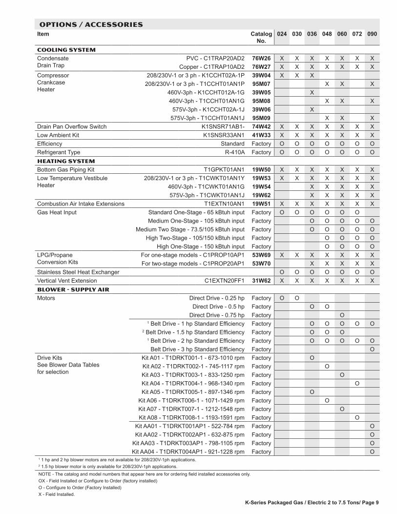
OPTIONS / ACCESSORIESItem Catalog
No.024 030 036 048 060 072 090
COOLING SYSTEM
Condensate Drain Trap
PVC - C1TRAP20AD2 76W26 X X X X X X XCopper - C1TRAP10AD2 76W27 X X X X X X X
Compressor Crankcase Heater
208/230V-1 or 3 ph - K1CCHT02A-1P 39W04 X X X208/230V-1 or 3 ph - T1CCHT01AN1P 95M07 X X X
460V-3ph - K1CCHT012A-1G 39W05 X460V-3ph - T1CCHT01AN1G 95M08 X X X
575V-3ph - K1CCHT02A-1J 39W06 X575V-3ph - T1CCHT01AN1J 95M09 X X X
Drain Pan Overflow Switch K1SNSR71AB1- 74W42 X X X X X X XLow Ambient Kit K1SNSR33AN1 41W33 X X X X X X XEfficiency Standard Factory O O O O O O ORefrigerant Type R-410A Factory O O O O O O OHEATING SYSTEM
Bottom Gas Piping Kit T1GPKT01AN1 19W50 X X X X X X XLow Temperature Vestibule Heater
208/230V-1 or 3 ph - T1CWKT01AN1Y 19W53 X X X X X X X460V-3ph - T1CWKT01AN1G 19W54 X X X X X575V-3ph - T1CWKT01AN1J 19W62 X X X X X
Combustion Air Intake Extensions T1EXTN10AN1 19W51 X X X X X X XGas Heat Input Standard One-Stage - 65 kBtuh input Factory O O O O O O
Medium One-Stage - 105 kBtuh input Factory O O O O OMedium Two Stage - 73.5/105 kBtuh input Factory O O O O O
High Two-Stage - 105/150 kBtuh input Factory O O O OHigh One-Stage - 150 kBtuh input Factory O O O O
LPG/Propane Conversion Kits
For one-stage models - C1PROP10AP1 53W69 X X X X X X XFor two-stage models - C1PROP20AP1 53W70 X X X X X
Stainless Steel Heat Exchanger O O O O O O OVertical Vent Extension C1EXTN20FF1 31W62 X X X X X X XBlower - SUPPLY AIR
Motors Direct Drive - 0.25 hp Factory O ODirect Drive - 0.5 hp Factory O O
Direct Drive - 0.75 hp Factory O1 Belt Drive - 1 hp Standard Efficiency Factory O O O O O
2 Belt Drive - 1.5 hp Standard Efficiency Factory O O O1 Belt Drive - 2 hp Standard Efficiency Factory O O O O O
Belt Drive - 3 hp Standard Efficiency Factory ODrive Kits See Blower Data Tables for selection
Kit A01 - T1DRKT001-1 - 673-1010 rpm Factory OKit A02 - T1DRKT002-1 - 745-1117 rpm Factory OKit A03 - T1DRKT003-1 - 833-1250 rpm Factory OKit A04 - T1DRKT004-1 - 968-1340 rpm Factory OKit A05 - T1DRKT005-1 - 897-1346 rpm Factory O
Kit A06 - T1DRKT006-1 - 1071-1429 rpm Factory OKit A07 - T1DRKT007-1 - 1212-1548 rpm Factory OKit A08 - T1DRKT008-1 - 1193-1591 rpm Factory O
Kit AA01 - T1DRKT001AP1 - 522-784 rpm Factory OKit AA02 - T1DRKT002AP1 - 632-875 rpm Factory O
Kit AA03 - T1DRKT003AP1 - 798-1105 rpm Factory OKit AA04 - T1DRKT004AP1 - 921-1228 rpm Factory O
1 1 hp and 2 hp blower motors are not available for 208/230V-1ph applications.2 1.5 hp blower motor is only available for 208/230V-1ph applications.
NOTE - The catalog and model numbers that appear here are for ordering field installed accessories only.OX - Field Installed or Configure to Order (factory installed)O - Configure to Order (Factory Installed)X - Field Installed.
K-Series Packaged Gas / Electric 2 to 7.5 Tons / Page 10
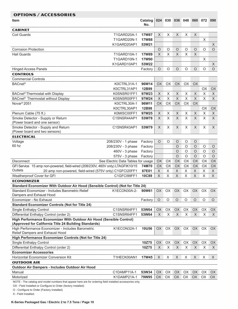
OPTIONS / ACCESSORIESItem Catalog
No.024 030 036 048 060 072 090
CABINETCoil Guards T1GARD20A-1 17W87 X X X X X
T1GARD20N-1 17W88 XK1GARD20AP1 53W21 X
Corrosion Protection O O O O O O OHail Guards T1GARD10A-1 17W89 X X X X X
T1GARD10N-1 17W90 XK1GARD10AP1 53W22 X
Hinged Access Panels Factory O O O O O O OCONTROLSCommercial ControlsBACnet® K0CTRL31A-1 96W14 OX OX OX OX OX
K0CTRL31AP1 12B99 OX OXBACnet® Thermostat with Display K0SNSR01FF1 97W23 X X X X X X XBACnet® Thermostat without Display K0SNSR00FF1 97W24 X X X X X X XNovar® 2051 K0CTRL30A-1 96W11 OX OX OX OX OX
K0CTRL30AP1 12B98 OX OXPlenum Cable (75 ft.) K0MISC00FF1 97W25 X X X X X X XSmoke Detector - Supply or Return (Power board and one sensor)
C1SNSR44AP1 53W78 X X X X X X X
Smoke Detector - Supply and Return (Power board and two sensors)
C1SNSR43AP1 53W79 X X X X X X X
ELECTRICALVoltage 60 hz
208/230V - 1 phase Factory O O O O O208/230V - 3 phase Factory O O O O O
460V - 3 phase Factory O O O O O575V - 3 phase Factory O O O O O
Disconnect See Electric Data Tables for usage OX OX OX OX OX OX OXGFI Service Outlets
15 amp non-powered, field-wired (208/230V, 460V only) LTAGFIK10/15 74M70 OX OX OX OX OX OX OX20 amp non-powered, field-wired (575V only) C1GFCI20FF1 67E01 X X X X X X X
Weatherproof Cover for GFI C1GFCI99FF1 10C89 X X X X X X XECONOMIZERStandard Economizer With Outdoor Air Hood (Sensible Control) (Not for Title 24)Standard Economizer - Includes Barometric Relief Dampers and Exhaust Hood
K1ECON30A-2- 90W61 OX OX OX OX OX OX OX
Economizer - No Exhaust Factory O O O O O O OStandard Economizer Controls (Not for Title 24)Single Enthalpy Control C1SNSR64FF1 53W64 OX OX OX OX OX OX OXDifferential Enthalpy Control (order 2) C1SNSR64FF1 53W64 X X X X X X X High Performance Economizer With Outdoor Air Hood (Sensible Control) (Approved for California Title 24 Building Standards)High Performance Economizer - Includes Barometric Relief Dampers and Exhaust Hood
K1ECON32A-1 10U56 OX OX OX OX OX OX OX
High Performance Economizer Controls (Not for Title 24)Single Enthalpy Control 10Z75 OX OX OX OX OX OX OXDifferential Enthalpy Control (order 2) 10Z75 X X X X X X X Economizer AccessoriesHorizontal Economizer Conversion Kit T1HECK00AN1 17W45 X X X X X X XOUTDOOR AIROutdoor Air Dampers - Includes Outdoor Air HoodManual C1DAMP11A-1 53W34 OX OX OX OX OX OX OXMotorized K1DAMP21A-1 79W95 OX OX OX OX OX OX OXNOTE - The catalog and model numbers that appear here are for ordering field installed accessories only.OX - Field Installed or Configure to Order (factory installed)O - Configure to Order (Factory Installed)X - Field Installed.

K-Series Packaged Gas / Electric 2 to 7.5 Tons/ Page 11
OPTIONS / ACCESSORIESItem Catalog
No.024 030 036 048 060 072 090
Power EXhaust FANStandard Static NOTE - Order Barometric Relief Dampers with Exhaust Hood below if unit is ordered with factory installed Economizer with “No Exhaust” option
208/230V-1 or 3ph - C1PWRE10A-1P 79W87 X X X X X460V-3ph - C1PWRE10A-1G 79W88 X X X X X575V-3ph - C1PWRE10A-1J 79W89 X X X X X
1 BAROMETRIC RELIEFBarometric Relief Dampers with Exhaust Hood C1DAMP50A-1- 74W38 X X X X X X XIndoor Air QualityAir FiltersHigh Efficiency Air FiltersOrder 4 per unit
MERV 8 (16 x 20 x 2) - C1FLTR15A-1- 54W20 X X X X XMERV 13 (16 x 20 x 2) - T1FLTR40A-1- 52W37 X X X X XMERV 8 (20 x 20 x 2) - C1FLTR15D-1- 54W21 X X
MERV 13 (20 x 20 x 2) - C1FLTR40D-1- 52W39 X XIndoor Air Quality (Co2) SensorsSensor - Wall-mount, off-white plastic cover with LCD display C0SNSR50AE1L 77N39 X X X X X X XSensor - Wall-mount, black plastic case, no display, rated for plenum mounting
C0SNSR53AE1L 87N54 X X X X X X X
CO2 Sensor Duct Mounting Kit - for downflow applications C0MISC19AE1- 85L43 X X X X X X XAspiration Box - for duct mounting non-plenum rated CO2 sensor (77N39)
C0MISC16AE1- 90N43 X X X X X X X
UVC Germicidal Lamps2 UVC Light Kit (208/230v-1ph) E1UVCL10AN1- 50W90 X X X X X X XCEILING DIFFUSERSStep-Down - Order one RTD9-65-R 27G87 X X X X X
RTD11-95 29G04 X XFlush - Order one FD9-65-R 27G86 X X X X X
FD11-95 29G08 X XTransitions (Supply and Return) - Order one T1TRAN10AN1 17W53 X X X X X
T1TRAN20N-1 17W54 X XROOF CURBSHybrid Roof Curbs, Downflow8 in. height C1CURB70A-1 11F50 X X X X X X 2 X14 in. height C1CURB71A-1 11F51 X X X X X X 2 X18 in. height C1CURB72A-1 11F52 X X X X X X 2 X24 in. height C1CURB73A-1 11F53 X X X X X X 2 XClip Curbs, Full Perimeter, Downflow8 in. height K1CURB23AP1 52W20 X14 in. height K1CURB20AP1 52W21 X18 in. height K1CURB21AP1 52W22 X24 in. height K1CURB22AP1 52W23 XHinged, Full Perimeter, Downflow8 in. height K1CURB30AP1 52W17 X14 in. height K1CURB32AP1 52W18 X24 in. height K1CURB33AP1 52W19 XStandard, Full Perimeter, Downflow14 in. height K1CURB10AP1 52W24 XAdjustable Pitched Curb14 in. height C1CURB55AT1 43W27 X X X X X X 2 X1 Required when Economizer is factory installed (no exhaust option) with field installed Power Exhaust Fan option.2 Lamps operate on 110-230V single-phase power supply. Step-down transformer may be ordered separately for 460V and 575V units. Alternately, 110V power supply
may be used to directly power the UVC ballast(s).3 090 models fit smaller roof curbs with overhang. See dimension drawing.NOTE - The catalog and model numbers that appear here are for ordering field installed accessories only.OX - Field Installed or Configure to Order (factory installed)O - Configure to Order (Factory Installed)X - Field Installed.

K-Series Packaged Gas / Electric 2 to 7.5 Tons / Page 12
SPECIFICATIONS - DIRECT DRIVE BLOWERGeneral Data Nominal Tonnage 2 Ton 2.5 Ton
Model No. KGA024S4D KGA030S4DEfficiency Type Standard Standard
Cooling Performance
Gross Cooling Capacity - Btuh 24,400 29,8001 Net Cooling Capacity - Btuh 23,600 28,800
AHRI Rated Air Flow - cfm 840 10002 Sound Rating Number (SRN) (dBA) 75 75
Total Unit Power - kW 2.1 2.61 SEER (Btuh/Watt) 13 13
1 EER (Btuh/Watt) 11.4 11.2Refrigerant Type R-410A R-410A
Charge Furnished 7 lbs. 0 oz. 7 lbs. 12 oz.Gas Heating Options - See page 15 Standard (1 Stage) Standard (1 Stage)Compressor Type (one per unit) Scroll ScrollOutdoor Coil Net face area - sq. ft. 15.6 15.6
Tube diameter - in. 3/8 3/8Number of rows 1 1
Fins per inch 20 20Outdoor Coil Fan
Motor HP 1/4 1/4Motor rpm 825 825
Total motor watts 250 250Diameter - in. / No. of blades 24 - 3 24 - 3
Total air volume - cfm 3700 3700Indoor Coil Net face area - sq. ft. 7.8 7.8
Tube diameter - in. 3/8 3/8Number of rows 3 3
Fins per inch 14 14Drain Connection (no. and size) - in. (1) 1 npt (1) 1 npt
Expansion device type Balanced Port Thermostatic Expansion Valve, removeable power headIndoor Blower Nominal Motor HP .25 .25
Wheel nominal diameter x width - in. 10 x 10 10 x 10Filters Type Disposable
Number and size - in. (4) 16 x 20 x 2Electrical Characteristics - 60 Hz 208/230V
1 phase208/230V 1 phase
NOTE - Net capacity includes evaporator blower motor heat deduction. Gross capacity does not include evaporator blower motor heat deduction.1 AHRI Certified to AHRI Standard 210/240: 95°F outdoor air temperature and 80°F db/67°F wb entering evaporator air; minimum external duct static pressure.2 Sound Rating Number (SRN) rated in accordance with test conditions included in ARI Standard 270-95.

K-Series Packaged Gas / Electric 2 to 7.5 Tons/ Page 13
SPECIFICATIONS - DIRECT DRIVE BLOWER General Data Nominal Tonnage 3 Ton 4 Ton 5 Ton
Model No. KGA036S4D KGA048S4D KGA060S4DEfficiency Type Standard Standard Standard
Cooling Performance
Gross Cooling Capacity - Btuh 37,500 50,000 61,8001 Net Cooling Capacity - Btuh 36,000 48,000 59,000
AHRI Rated Air Flow - cfm 1200 1600 18002 Sound Rating Number (SRN) (dBA) 75 75 82
Total Unit Power - kW 3.4 4.4 5.31 SEER (Btuh/Watt) 13 13 13
1 EER (Btuh/Watt) 10.7 11 11.2Refrigerant Type R-410A R-410A R-410A
Charge Furnished 8 lbs. 5 oz. 8 lbs. 10 oz. 11 lbs. 0 oz.Gas Heating Options - See page 15 Standard (1 stage) or
Medium (1 or 2 stage)Standard (1 stage),
Medium (1 or 2 Stage) or High (1 or 2 Stage)
Compressor Type (one per unit) Scroll Scroll ScrollOutdoor Coil Net face area - sq. ft. 15.6 15.6 15.6
Tube diameter - in. 3/8 3/8 3/8Number of rows 1 1.5 2
Fins per inch 20 20 20Outdoor Coil Fan
Motor HP 1/4 1/4 1/3Motor rpm 825 825 1075
Total motor watts 250 250 370Diameter - in. / No. of blades 24 - 3 24 - 3 24 - 3
Total air volume - cfm 3700 3500 4300Indoor Coil Net face area - sq. ft. 7.8 7.8 7.8
Tube diameter - in. 3/8 3/8 3/8Number of rows 3 3 4
Fins per inch 14 14 14Drain Connection (no. and size) - in. (1) 1 npt (1) 1 npt (1) 1 npt
Expansion device type Balanced Port Thermostatic Expansion Valve, removeable power headIndoor Blower
Nominal Motor HP .5 .5 .75Wheel nominal diameter x width - in. 10 x 10 10 x 10 11 x 10
Filters Type DisposableNumber and size - in. (4) 16 x 20 x 2
Electrical Characteristics - 60 Hz 208/230V 1 phase
208/230V,
460V & 575V 3 phase
208/230V 1 phase
208/230V,
460V & 575V 3 phase
208/230V 1 phase
208/230V,
460V & 575V 3 phase
NOTE - Net capacity includes evaporator blower motor heat deduction. Gross capacity does not include evaporator blower motor heat deduction.1 AHRI Certified to AHRI Standard 210/240: 95°F outdoor air temperature and 80°F db/67°F wb entering evaporator air; minimum external duct static pressure.2 Sound Rating Number (SRN) rated in accordance with test conditions included in ARI Standard 270-95.
K-Series Packaged Gas / Electric 2 to 7.5 Tons / Page 14
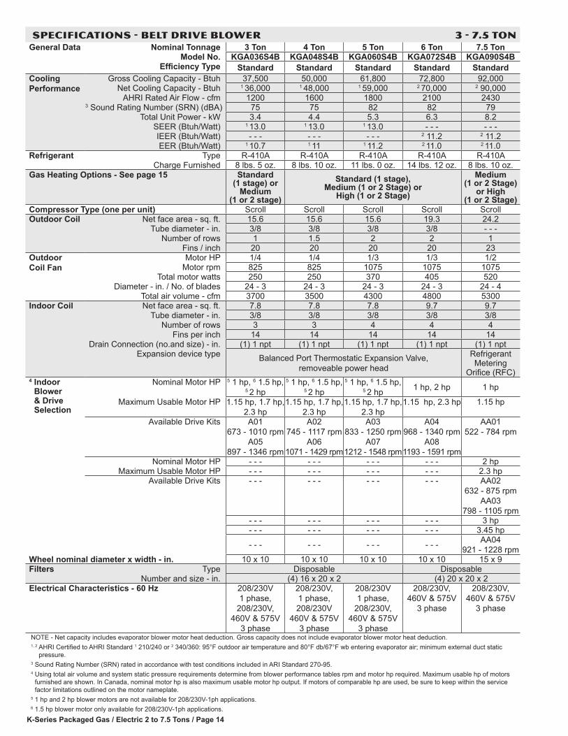
SPECIFICATIONS - BELT DRIVE BLOWER 3 - 7.5 TONGeneral Data Nominal Tonnage 3 Ton 4 Ton 5 Ton 6 Ton 7.5 Ton
Model No. KGA036S4B KGA048S4B KGA060S4B KGA072S4B KGA090S4BEfficiency Type Standard Standard Standard Standard Standard
Cooling Performance
Gross Cooling Capacity - Btuh 37,500 50,000 61,800 72,800 92,000Net Cooling Capacity - Btuh 1 36,000 1 48,000 1 59,000 2 70,000 2 90,000
AHRI Rated Air Flow - cfm 1200 1600 1800 2100 24303 Sound Rating Number (SRN) (dBA) 75 75 82 82 79
Total Unit Power - kW 3.4 4.4 5.3 6.3 8.2SEER (Btuh/Watt) 1 13.0 1 13.0 1 13.0 - - - - - -IEER (Btuh/Watt) - - - - - - - - - 2 11.2 2 11.2EER (Btuh/Watt) 1 10.7 1 11 1 11.2 2 11.0 2 11.0
Refrigerant Type R-410A R-410A R-410A R-410A R-410ACharge Furnished 8 lbs. 5 oz. 8 lbs. 10 oz. 11 lbs. 0 oz. 14 lbs. 12 oz. 8 lbs. 10 oz.
Gas Heating Options - See page 15 Standard (1 stage) or
Medium (1 or 2 stage)
Standard (1 stage), Medium (1 or 2 Stage) or
High (1 or 2 Stage)
Medium (1 or 2 Stage)
or High (1 or 2 Stage)
Compressor Type (one per unit) Scroll Scroll Scroll Scroll ScrollOutdoor Coil Net face area - sq. ft. 15.6 15.6 15.6 19.3 24.2
Tube diameter - in. 3/8 3/8 3/8 3/8 - - -Number of rows 1 1.5 2 2 1
Fins / inch 20 20 20 20 23Outdoor Coil Fan
Motor HP 1/4 1/4 1/3 1/3 1/2Motor rpm 825 825 1075 1075 1075
Total motor watts 250 250 370 405 520Diameter - in. / No. of blades 24 - 3 24 - 3 24 - 3 24 - 3 24 - 4
Total air volume - cfm 3700 3500 4300 4800 5300Indoor Coil Net face area - sq. ft. 7.8 7.8 7.8 9.7 9.7
Tube diameter - in. 3/8 3/8 3/8 3/8 3/8Number of rows 3 3 4 4 4
Fins per inch 14 14 14 14 14Drain Connection (no.and size) - in. (1) 1 npt (1) 1 npt (1) 1 npt (1) 1 npt (1) 1 npt
Expansion device type Balanced Port Thermostatic Expansion Valve, removeable power head
Refrigerant Metering
Orifice (RFC)4 Indoor
Blower & Drive Selection
Nominal Motor HP 5 1 hp, 6 1.5 hp, 5 2 hp
5 1 hp, 6 1.5 hp, 5 2 hp
5 1 hp, 6 1.5 hp, 5 2 hp 1 hp, 2 hp 1 hp
Maximum Usable Motor HP 1.15 hp, 1.7 hp, 2.3 hp
1.15 hp, 1.7 hp, 2.3 hp
1.15 hp, 1.7 hp, 2.3 hp
1.15 hp, 2.3 hp 1.15 hp
Available Drive Kits A01 673 - 1010 rpm
A05 897 - 1346 rpm
A02 745 - 1117 rpm
A06 1071 - 1429 rpm
A03 833 - 1250 rpm
A07 1212 - 1548 rpm
A04 968 - 1340 rpm
A08 1193 - 1591 rpm
AA01 522 - 784 rpm
Nominal Motor HP - - - - - - - - - - - - 2 hpMaximum Usable Motor HP - - - - - - - - - - - - 2.3 hp
Available Drive Kits - - - - - - - - - - - - AA02 632 - 875 rpm
AA03 798 - 1105 rpm
- - - - - - - - - - - - 3 hp- - - - - - - - - - - - 3.45 hp
- - - - - - - - - - - - AA04 921 - 1228 rpm
Wheel nominal diameter x width - in. 10 x 10 10 x 10 10 x 10 10 x 10 15 x 9Filters Type Disposable Disposable
Number and size - in. (4) 16 x 20 x 2 (4) 20 x 20 x 2Electrical Characteristics - 60 Hz 208/230V
1 phase, 208/230V,
460V & 575V 3 phase
208/230V, 1 phase, 208/230V
460V & 575V 3 phase
208/230V 1 phase,
208/230V, 460V & 575V
3 phase
208/230V, 460V & 575V
3 phase
208/230V, 460V & 575V
3 phase
NOTE - Net capacity includes evaporator blower motor heat deduction. Gross capacity does not include evaporator blower motor heat deduction.1, 2 AHRI Certified to AHRI Standard 1 210/240 or 2 340/360: 95°F outdoor air temperature and 80°F db/67°F wb entering evaporator air; minimum external duct static
pressure.3 Sound Rating Number (SRN) rated in accordance with test conditions included in ARI Standard 270-95.4 Using total air volume and system static pressure requirements determine from blower performance tables rpm and motor hp required. Maximum usable hp of motors
furnished are shown. In Canada, nominal motor hp is also maximum usable motor hp output. If motors of comparable hp are used, be sure to keep within the service factor limitations outlined on the motor nameplate.
5 1 hp and 2 hp blower motors are not available for 208/230V-1ph applications.6 1.5 hp blower motor only available for 208/230V-1ph applications.
K-Series Packaged Gas / Electric 2 to 7.5 Tons/ Page 15
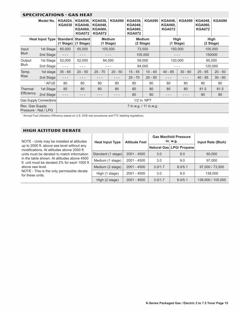
SPECIFICATIONS - GAS HEATModel No. KGA024,
KGA030KGA036, KGA048, KGA060, KGA072
KGA036, KGA048, KGA060, KGA072
KGA090 KGA036, KGA048, KGA060, KGA072
KGA090 KGA048, KGA060, KGA072
KGA090 KGA048, KGA060, KGA072
KGA090
Heat Input Type Standard (1 Stage)
Standard (1 Stage)
Medium (1 Stage)
Medium (2 Stage)
High (1 Stage)
High (2 Stage)
Input Btuh
1st Stage 65,000 65,000 105,000 73,500 150,000 105,0002nd Stage - - - - - - - - - 105,000 - - - 150000
Output Btuh
1st Stage 52,000 52,000 84,000 59,000 120,000 85,5002nd Stage - - - - - - - - - 84,000 - - - 120,000
Temp. Rise
1st stage 35 - 65 20 - 50 25 - 70 20 - 50 15 - 55 10 - 40 40 - 85 30 - 60 25 - 65 20 - 502nd Stage - - - - - - - - - - - - 25 - 70 20 - 50 - - - - - - 40 - 85 30 - 60
1 AFUE 80 80 80 80 80 80 80 80 80 80Thermal Efficiency
1st Stage 80 80 80 80 80 80 80 80 81.5 81.52nd Stage - - - - - - - - - - - - 80 80 - - - - - - 80 80
Gas Supply Connections 1/2 in. NPTRec. Gas Supply Pressure - Nat./ LPG
7 in.w.g. / 11 in.w.g.
1 Annual Fuel Utilization Efficiency based on U.S. DOE test procedures and FTC labeling regulations.
HIGH ALTITUDE DERATE
NOTE - Units may be installed at altitudes up to 2000 ft. above sea level without any modifications. At altitudes above 2000 ft. units must be derated to match information in the table shown. At altitudes above 4500 ft. unit must be derated 2% for each 1000 ft. above sea level. NOTE - This is the only permissible derate for these units.
Heat Input Type Altitude Feet Gas Manifold Pressure
in. w.g. Input Rate (Btuh) Natural Gas LPG/ Propane
Standard (1 stage) 2001 - 4500 3.0 9.0 60,000
Medium (1 stage) 2001 - 4500 3.0 9.0 97,000
Medium (2 stage) 2001 - 4500 3.0/1.7 9.0/5.1 97,000 / 73,500
High (1 stage) 2001 - 4500 3.0 9.0 138,000
High (2 stage) 2001 - 4500 3.0/1.7 9.0/5.1 138,000 / 105,000
K-Series Packaged Gas / Electric 2 to 7.5 Tons / Page 16
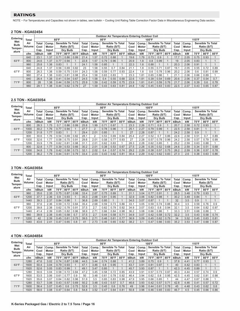
RATINGSNOTE − For Temperatures and Capacities not shown in tables, see bulletin − Cooling Unit Rating Table Correction Factor Data in Miscellaneous Engineering Data section.
2 TON - KGA024S4
Entering Wet Bulb
Temper-ature
Total Air
Volume
Outdoor Air Temperature Entering Outdoor Coil85°F 95°F 105°F 115°F
Total Cool Cap.
Comp. Motor Input
Sensible To Total Ratio (S/T)
Total Cool Cap.
Comp. Motor Input
Sensible To Total Ratio (S/T)
Total Cool Cap.
Comp. Motor Input
Sensible To Total Ratio (S/T)
Total Cool Cap.
Comp. Motor Input
Sensible To Total Ratio (S/T)
Dry Bulb Dry Bulb Dry Bulb Dry Bulbcfm kBtuh kW 75°F 80°F 85°F kBtuh kW 75°F 80°F 85°F kBtuh kW 75°F 80°F 85°F kBtuh kW 75°F 80°F 85°F
63°F640 23.1 1.37 0.71 0.86 0.99 21.4 1.57 0.72 0.88 1 19.6 1.79 0.73 0.9 1 17.7 2.05 0.75 0.93 1800 24.6 1.37 0.77 0.94 1 22.8 1.57 0.79 0.96 1 20.9 1.8 0.8 0.99 1 19 2.05 0.83 1 1960 25.8 1.38 0.83 1 1 24.1 1.58 0.85 1 1 22.3 1.8 0.88 1 1 20.3 2.06 0.91 1 1
67°F640 24.8 1.37 0.56 0.69 0.82 23 1.58 0.55 0.7 0.84 21.1 1.8 0.55 0.71 0.87 19.1 2.05 0.55 0.72 0.89800 26.3 1.38 0.59 0.75 0.91 24.3 1.58 0.59 0.77 0.93 22.4 1.8 0.6 0.78 0.96 20.2 2.06 0.6 0.81 0.99960 27.4 1.38 0.63 0.81 0.98 25.4 1.58 0.63 0.83 1 23.3 1.81 0.65 0.86 1 21.1 2.06 0.66 0.89 1
71°F640 26.4 1.38 0.41 0.54 0.67 24.5 1.58 0.4 0.55 0.68 22.6 1.81 0.39 0.54 0.69 20.6 2.06 0.37 0.54 0.7800 28 1.38 0.44 0.59 0.73 25.9 1.59 0.42 0.59 0.75 23.9 1.81 0.41 0.59 0.76 21.7 2.06 0.39 0.6 0.78960 29.1 1.38 0.44 0.62 0.79 27 1.59 0.43 0.63 0.81 24.8 1.82 0.45 0.63 0.83 22.5 2.07 0.43 0.65 0.87
2.5 TON - KGA030S4
Entering Wet Bulb
Temper-ature
Total Air
Volume
Outdoor Air Temperature Entering Outdoor Coil85°F 95°F 105°F 115°F
Total Cool Cap.
Comp. Motor Input
Sensible To Total Ratio (S/T)
Total Cool Cap.
Comp. Motor Input
Sensible To Total Ratio (S/T)
Total Cool Cap.
Comp. Motor Input
Sensible To Total Ratio (S/T)
Total Cool Cap.
Comp. Motor Input
Sensible To Total Ratio (S/T)
Dry Bulb Dry Bulb Dry Bulb Dry Bulbcfm kBtuh kW 75°F 80°F 85°F kBtuh kW 75°F 80°F 85°F kBtuh kW 75°F 80°F 85°F kBtuh kW 75°F 80°F 85°F
63°F800 28.3 1.75 0.7 0.86 0.99 25.8 1.99 0.71 0.87 1 23.3 2.26 0.71 0.9 1 20.7 2.58 0.72 0.93 1
1000 30.2 1.76 0.77 0.94 1 27.7 2 0.78 0.96 1 25.1 2.27 0.79 0.99 1 22.5 2.58 0.81 1 11200 31.8 1.77 0.83 1 1 29.4 2.01 0.85 1 1 27 2.28 0.87 1 1 24.2 2.58 0.9 1 1
67°F800 30.6 1.76 0.54 0.69 0.82 28.1 2 0.53 0.69 0.84 25.4 2.27 0.52 0.7 0.86 22.6 2.58 0.51 0.7 0.89
1000 32.6 1.77 0.58 0.75 0.91 29.8 2.01 0.58 0.77 0.93 27 2.28 0.57 0.78 0.96 24.2 2.58 0.57 0.79 0.991200 33.9 1.78 0.62 0.81 0.98 31.1 2.01 0.62 0.83 1 28.3 2.28 0.62 0.85 1 25.2 2.59 0.63 0.88 1
71°F800 32.8 1.77 0.39 0.53 0.66 30.2 2.01 0.38 0.53 0.67 27.5 2.28 0.35 0.52 0.68 24.6 2.59 0.34 0.51 0.68
1000 34.8 1.78 0.42 0.58 0.73 32.1 2.02 0.4 0.57 0.74 29.2 2.29 0.38 0.57 0.75 26.2 2.59 0.36 0.57 0.781200 36.2 1.79 0.44 0.61 0.79 33.4 2.03 0.43 0.62 0.81 30.4 2.29 0.42 0.62 0.83 27.3 2.6 0.38 0.63 0.86
3 TON - KGA036S4
Entering Wet Bulb
Temper-ature
Total Air
Volume
Outdoor Air Temperature Entering Outdoor Coil85°F 95°F 105°F 115°F
Total Cool Cap.
Comp. Motor Input
Sensible To Total Ratio (S/T)
Total Cool Cap.
Comp. Motor Input
Sensible To Total Ratio (S/T)
Total Cool Cap.
Comp. Motor Input
Sensible To Total Ratio (S/T)
Total Cool Cap.
Comp. Motor Input
Sensible To Total Ratio (S/T)
Dry Bulb Dry Bulb Dry Bulb Dry Bulbcfm kBtuh kW 75°F 80°F 85°F kBtuh kW 75°F 80°F 85°F kBtuh kW 75°F 80°F 85°F kBtuh kW 75°F 80°F 85°F
63°F960 35.6 2.35 0.75 0.87 0.98 33.4 2.67 0.75 0.89 1 31.1 3.04 0.77 0.91 1 28.5 3.48 0.79 0.93 1
1200 37.7 2.36 0.8 0.93 1 35.3 2.68 0.81 0.95 1 32.9 3.06 0.82 0.98 1 30.2 3.49 0.84 1 11440 39.3 2.37 0.84 0.98 1 36.8 2.69 0.85 1 1 34.5 3.07 0.87 1 1 32 3.5 0.9 1 1
67°F960 37.6 2.36 0.59 0.72 0.84 35.4 2.68 0.59 0.73 0.86 33.1 3.05 0.59 0.74 0.88 30.4 3.5 0.59 0.76 0.9
1200 39.8 2.38 0.62 0.78 0.91 37.5 2.7 0.62 0.79 0.92 34.9 3.07 0.63 0.8 0.94 32.1 3.5 0.64 0.82 0.971440 41.4 2.39 0.65 0.82 0.96 38.9 2.71 0.66 0.84 0.98 36.2 3.08 0.66 0.86 1 33.3 3.51 0.68 0.88 1
71°F960 39.9 2.38 0.45 0.58 0.7 37.5 2.7 0.44 0.58 0.71 34.9 3.07 0.42 0.58 0.72 32.2 3.5 0.43 0.58 0.74
1200 42 2.39 0.45 0.61 0.75 39.5 2.71 0.46 0.61 0.77 36.9 3.09 0.45 0.62 0.79 34 3.52 0.45 0.63 0.811440 43.6 2.41 0.47 0.65 0.8 41 2.73 0.46 0.65 0.82 38.2 3.1 0.47 0.66 0.83 35.2 3.53 0.47 0.68 0.87
4 TON - KGA048S4
Entering Wet Bulb
Temper-ature
Total Air
Volume
Outdoor Air Temperature Entering Outdoor Coil85°F 95°F 105°F 115°F
Total Cool Cap.
Comp. Motor Input
Sensible To Total Ratio (S/T)
Total Cool Cap.
Comp. Motor Input
Sensible To Total Ratio (S/T)
Total Cool Cap.
Comp. Motor Input
Sensible To Total Ratio (S/T)
Total Cool Cap.
Comp. Motor Input
Sensible To Total Ratio (S/T)
Dry Bulb Dry Bulb Dry Bulb Dry Bulbcfm kBtuh kW 75°F 80°F 85°F kBtuh kW 75°F 80°F 85°F kBtuh kW 75°F 80°F 85°F kBtuh kW 75°F 80°F 85°F
63°F1280 47.6 3.02 0.74 0.87 0.98 44.5 3.44 0.74 0.88 1 41.2 3.89 0.75 0.9 1 37.8 4.41 0.77 0.93 11600 50.4 3.04 0.79 0.93 1 47.1 3.46 0.8 0.95 1 43.7 3.91 0.81 0.97 1 40 4.42 0.83 1 11920 52.6 3.05 0.83 0.99 1 49.1 3.47 0.85 1 1 45.7 3.93 0.87 1 1 42.3 4.45 0.89 1 1
67°F1280 50.6 3.04 0.58 0.72 0.84 47.2 3.45 0.58 0.72 0.85 43.9 3.91 0.57 0.73 0.87 40.3 4.44 0.57 0.74 0.91600 53.5 3.06 0.61 0.77 0.9 50 3.48 0.61 0.78 0.92 46.4 3.94 0.62 0.8 0.95 42.5 4.45 0.62 0.81 0.981920 55.6 3.07 0.64 0.82 0.96 51.9 3.5 0.65 0.83 0.98 47.9 3.95 0.66 0.85 1 44 4.47 0.67 0.88 1
71°F1280 53.7 3.06 0.43 0.57 0.69 50.2 3.48 0.43 0.57 0.7 46.6 3.93 0.42 0.57 0.71 42.8 4.46 0.41 0.57 0.721600 56.4 3.07 0.45 0.6 0.75 52.6 3.5 0.45 0.6 0.76 49 3.96 0.44 0.61 0.78 45 4.48 0.43 0.62 0.81920 58.6 3.08 0.47 0.64 0.8 54.8 3.52 0.47 0.64 0.81 50.8 3.98 0.46 0.65 0.83 46.7 4.5 0.45 0.66 0.86

K-Series Packaged Gas / Electric 2 to 7.5 Tons/ Page 17
RATINGSNOTE − For Temperatures and Capacities not shown in tables, see bulletin − Cooling Unit Rating Table Correction Factor Data in Miscellaneous Engineering Data section.
5 TON - KGA060S4
Entering Wet Bulb
Temper-ature
Total Air
Volume
Outdoor Air Temperature Entering Outdoor Coil85°F 95°F 105°F 115°F
Total Cool Cap.
Comp. Motor Input
Sensible To Total Ratio (S/T)
Total Cool Cap.
Comp. Motor Input
Sensible To Total Ratio (S/T)
Total Cool Cap.
Comp. Motor Input
Sensible To Total Ratio (S/T)
Total Cool Cap.
Comp. Motor Input
Sensible To Total Ratio (S/T)
Dry Bulb Dry Bulb Dry Bulb Dry Bulbcfm kBtuh kW 75°F 80°F 85°F kBtuh kW 75°F 80°F 85°F kBtuh kW 75°F 80°F 85°F kBtuh kW 75°F 80°F 85°F
63°F1600 60.1 3.48 0.68 0.84 1 57 3.93 0.69 0.86 1 53.5 4.44 0.71 0.89 1 50 5.04 0.73 0.93 12000 63.1 3.51 0.74 0.94 1 59.8 3.96 0.76 0.97 1 56 4.47 0.78 1 1 52.6 5.06 0.81 1 12400 65.6 3.54 0.8 1 1 62.3 3.99 0.83 1 1 59.1 4.51 0.86 1 1 55.6 5.1 0.91 1 1
67°F1600 63.9 3.52 0.54 0.66 0.79 60.5 3.97 0.54 0.67 0.82 57.1 4.48 0.55 0.69 0.85 53.2 5.07 0.56 0.71 0.892000 66.8 3.55 0.57 0.72 0.9 63.1 4 0.58 0.73 0.93 59.2 4.51 0.58 0.75 0.97 55.1 5.1 0.59 0.79 12400 68.9 3.58 0.6 0.78 0.99 65 4.02 0.61 0.8 1 61.1 4.54 0.63 0.84 1 56.8 5.12 0.64 0.88 1
71°F1600 67.7 3.56 0.4 0.52 0.64 64.2 4.01 0.41 0.53 0.65 60.4 4.53 0.4 0.54 0.67 56.4 5.12 0.4 0.54 0.692000 70.7 3.6 0.42 0.56 0.7 67 4.05 0.42 0.57 0.71 62.8 4.56 0.42 0.57 0.73 58.5 5.15 0.42 0.59 0.762400 72.7 3.62 0.43 0.59 0.75 68.7 4.07 0.43 0.6 0.78 64.6 4.58 0.44 0.62 0.81 60 5.17 0.44 0.64 0.85
6 TON - KGA072S4
Entering Wet Bulb
Temper-ature
Total Air
Volume
Outdoor Air Temperature Entering Outdoor Coil85°F 95°F 105°F 115°F
Total Cool Cap.
Comp. Motor Input
Sensible To Total Ratio (S/T)
Total Cool Cap.
Comp. Motor Input
Sensible To Total Ratio (S/T)
Total Cool Cap.
Comp. Motor Input
Sensible To Total Ratio (S/T)
Total Cool Cap.
Comp. Motor Input
Sensible To Total Ratio (S/T)
Dry Bulb Dry Bulb Dry Bulb Dry Bulbcfm kBtuh kW 75°F 80°F 85°F kBtuh kW 75°F 80°F 85°F kBtuh kW 75°F 80°F 85°F kBtuh kW 75°F 80°F 85°F
63°F1920 70 4.55 0.68 0.83 0.99 66.6 5.06 0.7 0.86 1 62.8 5.63 0.71 0.89 1 58.5 6.28 0.73 0.92 12400 73.8 4.57 0.74 0.93 1 70.1 5.07 0.76 0.96 1 66.1 5.64 0.78 0.99 1 61.8 6.29 0.8 1 12880 76.6 4.57 0.8 1 1 73.1 5.08 0.82 1 1 69.6 5.65 0.85 1 1 65.6 6.31 0.89 1 1
67°F1920 74.5 4.57 0.54 0.66 0.79 70.9 5.07 0.54 0.67 0.81 67 5.64 0.55 0.69 0.84 62.7 6.29 0.56 0.71 0.882400 78.3 4.58 0.57 0.71 0.89 74.5 5.08 0.58 0.73 0.92 70.3 5.65 0.59 0.75 0.95 65.6 6.3 0.6 0.77 0.982880 81.2 4.59 0.6 0.77 0.97 77 5.09 0.61 0.79 0.99 72.7 5.66 0.62 0.82 1 67.9 6.31 0.64 0.86 1
71°F1920 79.1 4.59 0.41 0.53 0.64 75 5.08 0.41 0.53 0.65 71.1 5.66 0.4 0.53 0.66 66.6 6.3 0.41 0.54 0.682400 83 4.6 0.42 0.56 0.69 79 5.1 0.42 0.57 0.7 74.5 5.67 0.42 0.58 0.72 69.9 6.32 0.42 0.59 0.752880 85.9 4.61 0.44 0.59 0.74 81.7 5.11 0.44 0.6 0.77 77 5.67 0.44 0.61 0.79 72.3 6.33 0.44 0.63 0.83
7.5 TON - KGA090S4
Entering Wet Bulb
Temper-ature
Total Air
Volume
Outdoor Air Temperature Entering Outdoor Coil85°F 95°F 105°F 115°F
Total Cool Cap.
Comp. Motor Input
Sensible To Total Ratio (S/T)
Total Cool Cap.
Comp. Motor Input
Sensible To Total Ratio (S/T)
Total Cool Cap.
Comp. Motor Input
Sensible To Total Ratio (S/T)
Total Cool Cap.
Comp. Motor Input
Sensible To Total Ratio (S/T)
Dry Bulb Dry Bulb Dry Bulb Dry Bulbcfm kBtuh kW 75°F 80°F 85°F kBtuh kW 75°F 80°F 85°F kBtuh kW 75°F 80°F 85°F kBtuh kW 75°F 80°F 85°F
63°F2400 92.4 5.97 0.69 0.84 0.98 85.3 6.6 0.7 0.86 1 77.8 7.32 0.7 0.88 1 69.9 8.15 0.71 0.91 13000 97.7 6.04 0.75 0.92 1 90.2 6.68 0.76 0.95 1 82.5 7.4 0.78 0.98 1 74.5 8.23 0.81 1 13600 101.9 6.11 0.81 1 1 94.6 6.75 0.83 1 1 87.2 7.48 0.85 1 1 79.5 8.33 0.89 1 1
67°F2400 99.4 6.07 0.54 0.67 0.81 91.8 6.7 0.53 0.68 0.83 84.2 7.43 0.53 0.68 0.85 75.9 8.26 0.52 0.7 0.883000 104.5 6.15 0.57 0.73 0.89 96.8 6.78 0.58 0.74 0.91 88.7 7.51 0.57 0.76 0.95 79.9 8.34 0.58 0.79 0.993600 108.5 6.21 0.61 0.79 0.97 100.2 6.84 0.62 0.81 0.99 92 7.57 0.62 0.84 1 82.7 8.39 0.62 0.87 1
71°F2400 106.2 6.17 0.4 0.53 0.65 98.5 6.81 0.38 0.52 0.66 90.6 7.54 0.37 0.52 0.67 82.2 8.38 0.36 0.52 0.683000 111.7 6.26 0.41 0.57 0.71 103.8 6.9 0.4 0.57 0.72 95.1 7.63 0.4 0.57 0.74 86.3 8.46 0.38 0.58 0.773600 115.6 6.33 0.44 0.6 0.77 107.2 6.96 0.43 0.61 0.79 98.6 7.69 0.42 0.62 0.82 89 8.51 0.41 0.63 0.85
K-Series Packaged Gas / Electric 2 to 7.5 Tons / Page 18
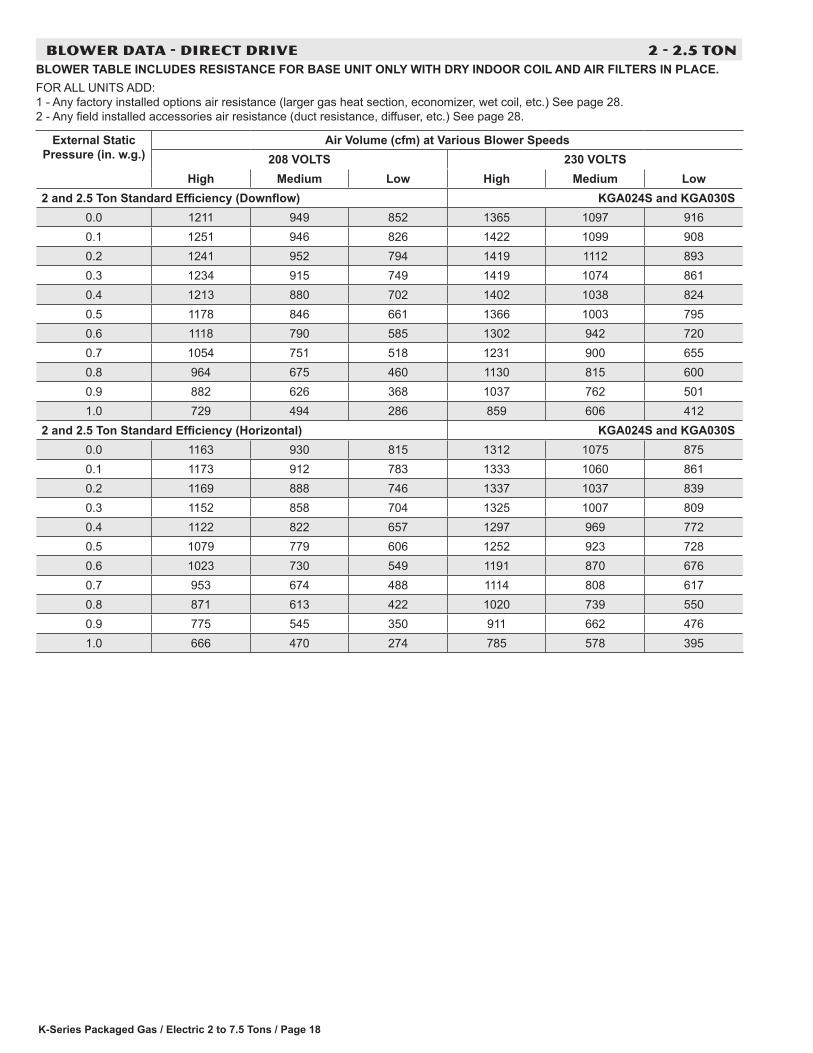
BLOWER DATA - DIRECT DRIVE 2 - 2.5 TONBLOWER TABLE INCLUDES RESISTANCE FOR BASE UNIT ONLY WITH DRY INDOOR COIL AND AIR FILTERS IN PLACE.FOR ALL UNITS ADD: 1 - Any factory installed options air resistance (larger gas heat section, economizer, wet coil, etc.) See page 28. 2 - Any field installed accessories air resistance (duct resistance, diffuser, etc.) See page 28.
External Static Pressure (in. w.g.)
Air Volume (cfm) at Various Blower Speeds208 VOLTS 230 VOLTS
High Medium Low High Medium Low2 and 2.5 Ton Standard Efficiency (Downflow) KGA024S and KGA030S
0.0 1211 949 852 1365 1097 9160.1 1251 946 826 1422 1099 9080.2 1241 952 794 1419 1112 8930.3 1234 915 749 1419 1074 8610.4 1213 880 702 1402 1038 8240.5 1178 846 661 1366 1003 7950.6 1118 790 585 1302 942 7200.7 1054 751 518 1231 900 6550.8 964 675 460 1130 815 6000.9 882 626 368 1037 762 5011.0 729 494 286 859 606 412
2 and 2.5 Ton Standard Efficiency (Horizontal) KGA024S and KGA030S0.0 1163 930 815 1312 1075 8750.1 1173 912 783 1333 1060 8610.2 1169 888 746 1337 1037 8390.3 1152 858 704 1325 1007 8090.4 1122 822 657 1297 969 7720.5 1079 779 606 1252 923 7280.6 1023 730 549 1191 870 6760.7 953 674 488 1114 808 6170.8 871 613 422 1020 739 5500.9 775 545 350 911 662 4761.0 666 470 274 785 578 395

K-Series Packaged Gas / Electric 2 to 7.5 Tons/ Page 19
BLOWER DATA - DIRECT DRIVE 3 - 4 TON
BLOWER TABLE INCLUDES RESISTANCE FOR BASE UNIT ONLY WITH DRY INDOOR COIL AND AIR FILTERS IN PLACE.FOR ALL UNITS ADD: 1 - Any factory installed options air resistance (larger gas heat section, economizer, wet coil, etc.) See page 28. 2 - Any field installed accessories air resistance (duct resistance, diffuser, etc.) See page 28.
External Static Pressure (in. w.g.)
Air Volume (cfm) at Various Blower Speeds208 VOLTS 230 VOLTS 460/575 VOLTS
High Medium Low High Medium Low High Medium Low3 and 4 Ton Standard Efficiency (Downflow) KGA036S and KGA048S
0.0 1873 1561 1123 2094 1783 1321 2064 1727 12160.1 1993 1601 1148 2168 1797 1338 2105 1744 12290.2 1913 1601 1137 2098 1803 1308 2050 1694 11980.3 1858 1527 1078 2036 1725 1261 1987 1638 11670.4 1801 1496 1046 1973 1679 1219 1905 1598 11480.5 1763 1467 987 1910 1647 1177 1862 1559 11080.6 1709 1414 897 1830 1560 1080 1781 1509 10570.7 1617 1368 806 1727 1519 986 1698 1449 9820.8 1472 1269 730 1604 1419 918 1614 1389 9200.9 1359 1162 487 1478 1363 706 1488 1346 7921.0 961 922 370 1093 1083 590 1167 1099 703
3 and 4 Ton Standard Efficiency (Horizontal) KGA036S and KGA048S0.0 1799 1530 1073 2012 1747 1263 2015 1756 12510.1 1868 1544 1088 2032 1733 1268 2071 1760 12790.2 1802 1494 1068 1976 1682 1228 2014 1700 12260.3 1735 1432 1014 1900 1618 1185 1937 1634 11870.4 1666 1397 980 1825 1568 1142 1878 1597 11740.5 1615 1350 904 1750 1516 1078 1801 1558 11240.6 1564 1305 842 1675 1440 1014 1743 1479 10600.7 1462 1228 758 1562 1364 928 1664 1415 9820.8 1330 1151 670 1449 1287 842 1512 1335 8650.9 1194 1011 464 1298 1185 671 1393 1297 7331.0 878 878 355 998 1032 565 1060 1063 618
K-Series Packaged Gas / Electric 2 to 7.5 Tons / Page 20
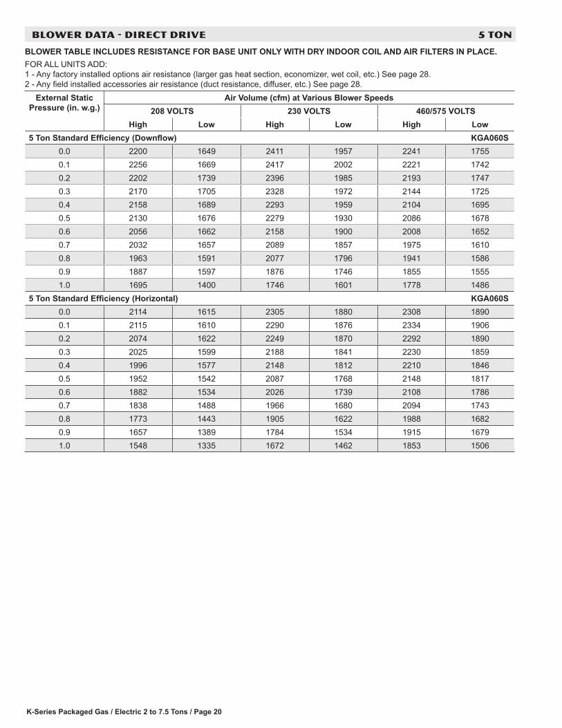
BLOWER DATA - DIRECT DRIVE 5 TON
BLOWER TABLE INCLUDES RESISTANCE FOR BASE UNIT ONLY WITH DRY INDOOR COIL AND AIR FILTERS IN PLACE.FOR ALL UNITS ADD: 1 - Any factory installed options air resistance (larger gas heat section, economizer, wet coil, etc.) See page 28. 2 - Any field installed accessories air resistance (duct resistance, diffuser, etc.) See page 28.
External Static Pressure (in. w.g.)
Air Volume (cfm) at Various Blower Speeds208 VOLTS 230 VOLTS 460/575 VOLTS
High Low High Low High Low5 Ton Standard Efficiency (Downflow) KGA060S
0.0 2200 1649 2411 1957 2241 17550.1 2256 1669 2417 2002 2221 17420.2 2202 1739 2396 1985 2193 17470.3 2170 1705 2328 1972 2144 17250.4 2158 1689 2293 1959 2104 16950.5 2130 1676 2279 1930 2086 16780.6 2056 1662 2158 1900 2008 16520.7 2032 1657 2089 1857 1975 16100.8 1963 1591 2077 1796 1941 15860.9 1887 1597 1876 1746 1855 15551.0 1695 1400 1746 1601 1778 1486
5 Ton Standard Efficiency (Horizontal) KGA060S0.0 2114 1615 2305 1880 2308 18900.1 2115 1610 2290 1876 2334 19060.2 2074 1622 2249 1870 2292 18900.3 2025 1599 2188 1841 2230 18590.4 1996 1577 2148 1812 2210 18460.5 1952 1542 2087 1768 2148 18170.6 1882 1534 2026 1739 2108 17860.7 1838 1488 1966 1680 2094 17430.8 1773 1443 1905 1622 1988 16820.9 1657 1389 1784 1534 1915 16791.0 1548 1335 1672 1462 1853 1506

K-Series Packaged Gas / Electric 2 to 7.5 Tons/ Page 21
BLOWER DATA - BELT DRIVE - KGA036
BLOWER TABLE INCLUDES RESISTANCE FOR BASE UNIT ONLY WITH DRY INDOOR COIL AND AIR FILTERS IN PLACE.FOR ALL UNITS ADD: 1 - Any factory installed options air resistance (heat section, economizer, wet coil, etc.). 2 - Any field installed accessories air resistance (duct resistance, diffuser, etc.). See page 28 for blower motors and drives and wet coil and options/accessory air resistance data.
DOWNFLOW
Air Volume
cfm
External Static - in. w.g.0.10 0.20 0.30 0.40 0.50 0.60 0.70 0.80
RPM BHP RPM BHP RPM BHP RPM BHP RPM BHP RPM BHP RPM BHP RPM BHPField Furnished Kit A01
900 493 0.11 564 0.15 637 0.19 711 0.22 783 0.24 851 0.26 910 0.29 961 0.321000 517 0.14 588 0.18 660 0.22 733 0.24 804 0.26 868 0.29 924 0.32 974 0.351100 544 0.17 614 0.21 685 0.25 757 0.27 826 0.29 887 0.32 940 0.36 987 0.381200 574 0.2 643 0.24 712 0.28 782 0.31 849 0.33 906 0.36 956 0.39 1001 0.421300 613 0.23 679 0.28 745 0.31 811 0.34 873 0.36 926 0.40 973 0.43 1016 0.461400 662 0.26 722 0.30 781 0.34 841 0.37 897 0.41 944 0.44 989 0.48 1032 0.511500 710 0.29 763 0.33 816 0.38 869 0.41 919 0.45 963 0.49 1006 0.53 1049 0.56
Air Volume
cfm
External Static - in. w.g.0.90 1.00 1.10 1.20 1.30 1.40 1.50 1.60
RPM BHP RPM BHP RPM BHP RPM BHP RPM BHP RPM BHP RPM BHP RPM BHPKit A01 Kit A05
900 1008 0.34 1056 0.36 1104 0.39 1149 0.41 1190 0.44 1229 0.46 1267 0.49 1305 0.521000 1020 0.37 1067 0.40 1115 0.42 1159 0.45 1200 0.48 1239 0.51 1277 0.54 1314 0.571100 1032 0.41 1078 0.43 1124 0.46 1168 0.49 1210 0.52 1249 0.55 1286 0.58 1323 0.621200 1045 0.45 1090 0.47 1135 0.50 1178 0.53 1220 0.57 1259 0.60 1296 0.64 1332 0.671300 1060 0.49 1104 0.51 1148 0.55 1190 0.58 1230 0.62 1269 0.65 1306 0.69 1342 0.721400 1075 0.53 1119 0.56 1162 0.60 1203 0.63 1242 0.67 1280 0.71 1317 0.75 1352 0.781500 1093 0.58 1136 0.61 1177 0.65 1217 0.69 1255 0.73 1292 0.77 1328 0.80 1364 0.84
HORIZONTAL
Air Volume
cfm
External Static - in. w.g.0.10 0.20 0.30 0.40 0.50 0.60 0.70 0.80
RPM BHP RPM BHP RPM BHP RPM BHP RPM BHP RPM BHP RPM BHP RPM BHPField Furnished Kit A01
900 465 0.09 531 0.14 600 0.17 670 0.20 740 0.22 808 0.24 869 0.27 925 0.301000 483 0.12 549 0.16 617 0.20 687 0.22 756 0.24 822 0.26 881 0.29 935 0.331100 504 0.14 570 0.19 637 0.22 706 0.25 773 0.27 837 0.29 894 0.32 946 0.361200 527 0.17 592 0.22 658 0.25 726 0.28 792 0.30 854 0.32 908 0.36 957 0.391300 552 0.20 617 0.25 682 0.29 748 0.31 812 0.33 871 0.36 923 0.40 970 0.431400 580 0.24 644 0.28 708 0.32 773 0.35 834 0.37 890 0.40 938 0.44 984 0.481500 611 0.28 674 0.32 736 0.35 799 0.38 857 0.41 908 0.44 954 0.49 998 0.52
Air Volume
cfm
External Static - in. w.g.0.90 1.00 1.10 1.20 1.30 1.40 1.50 1.60
RPM BHP RPM BHP RPM BHP RPM BHP RPM BHP RPM BHP RPM BHP RPM BHPKit A01 Kit A05
900 977 0.33 1028 0.36 1079 0.39 1127 0.42 1169 0.45 1208 0.48 1246 0.51 1282 0.541000 985 0.36 1036 0.39 1087 0.42 1135 0.45 1177 0.48 1216 0.52 1253 0.55 1290 0.581100 995 0.39 1044 0.42 1093 0.45 1140 0.49 1183 0.52 1223 0.56 1261 0.59 1297 0.621200 1005 0.43 1053 0.46 1100 0.49 1146 0.53 1190 0.56 1230 0.60 1268 0.63 1304 0.671300 1016 0.47 1063 0.50 1109 0.53 1154 0.57 1197 0.61 1237 0.64 1275 0.68 1311 0.721400 1029 0.51 1074 0.54 1120 0.58 1164 0.61 1205 0.65 1245 0.69 1282 0.73 1318 0.771500 1042 0.56 1087 0.59 1132 0.62 1174 0.66 1215 0.71 1253 0.75 1290 0.78 1326 0.82
K-Series Packaged Gas / Electric 2 to 7.5 Tons / Page 22
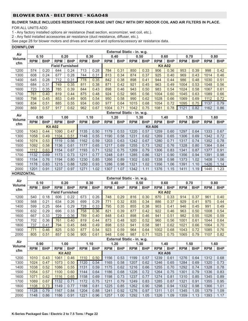
BLOWER DATA - BELT DRIVE - KGA048
BLOWER TABLE INCLUDES RESISTANCE FOR BASE UNIT ONLY WITH DRY INDOOR COIL AND AIR FILTERS IN PLACE.FOR ALL UNITS ADD: 1 - Any factory installed options air resistance (heat section, economizer, wet coil, etc.). 2 - Any field installed accessories air resistance (duct resistance, diffuser, etc.). See page 28 for blower motors and drives and wet coil and options/accessory air resistance data.
DOWNFLOW
Air Volume
cfm
External Static - in. w.g.0.10 0.20 0.30 0.40 0.50 0.60 0.70 0.80
RPM BHP RPM BHP RPM BHP RPM BHP RPM BHP RPM BHP RPM BHP RPM BHPField Furnished Kit A02
1200 574 0.20 644 0.24 713 0.28 784 0.31 850 0.33 906 0.36 953 0.39 998 0.421300 608 0.24 677 0.28 744 0.31 813 0.34 874 0.37 925 0.40 969 0.43 1014 0.461400 645 0.28 712 0.31 778 0.35 842 0.38 898 0.41 944 0.44 986 0.48 1030 0.511500 684 0.31 749 0.35 811 0.38 871 0.42 921 0.45 963 0.49 1004 0.53 1048 0.561600 723 0.35 785 0.39 844 0.43 898 0.46 943 0.50 983 0.54 1024 0.58 1067 0.611700 761 0.40 819 0.44 875 0.48 924 0.52 965 0.56 1004 0.60 1045 0.63 1089 0.661800 798 0.45 853 0.49 905 0.54 950 0.58 990 0.62 1028 0.66 1069 0.69 1112 0.721900 834 0.51 885 0.55 934 0.60 977 0.64 1015 0.68 1054 0.72 1095 0.75 1137 0.792000 869 0.57 917 0.62 962 0.67 1004 0.71 1042 0.75 1081 0.78 1121 0.82 1162 0.86
Air Volume
cfm
External Static - in. w.g.0.90 1.00 1.10 1.20 1.30 1.40 1.50 1.60
RPM BHP RPM BHP RPM BHP RPM BHP RPM BHP RPM BHP RPM BHP RPM BHPKit A02 Kit A06
1200 1043 0.44 1090 0.47 1135 0.50 1179 0.53 1220 0.57 1259 0.60 1297 0.64 1333 0.671300 1058 0.49 1104 0.51 1148 0.55 1190 0.58 1231 0.62 1269 0.65 1306 0.69 1342 0.721400 1074 0.53 1119 0.56 1162 0.59 1203 0.63 1242 0.67 1280 0.71 1317 0.74 1352 0.781500 1092 0.58 1136 0.61 1177 0.65 1217 0.69 1255 0.73 1292 0.76 1328 0.80 1364 0.841600 1112 0.63 1154 0.67 1193 0.71 1232 0.75 1269 0.79 1306 0.83 1341 0.87 1377 0.911700 1132 0.69 1173 0.73 1211 0.77 1248 0.81 1285 0.86 1321 0.90 1356 0.94 1391 0.981800 1154 0.76 1194 0.80 1230 0.85 1266 0.89 1302 0.93 1338 0.98 1373 1.02 1408 1.061900 1178 0.83 1215 0.88 1250 0.93 1286 0.98 1321 1.02 1356 1.06 1391 1.10 1426 1.142000 1201 0.91 1237 0.97 1271 1.02 1307 1.07 1342 1.11 1376 1.15 1411 1.19 1446 1.23
HORIZONTAL
Air Volume
cfm
External Static - in. w.g.0.10 0.20 0.30 0.40 0.50 0.60 0.70 0.80
RPM BHP RPM BHP RPM BHP RPM BHP RPM BHP RPM BHP RPM BHP RPM BHPField Furnished Kit A02
1200 540 0.18 606 0.22 673 0.26 748 0.29 816 0.30 870 0.33 914 0.37 961 0.401300 568 0.21 634 0.26 699 0.29 771 0.32 835 0.34 886 0.37 929 0.41 975 0.441400 599 0.25 664 0.29 728 0.33 795 0.35 855 0.38 903 0.41 946 0.45 991 0.491500 632 0.29 696 0.33 758 0.36 821 0.39 877 0.42 922 0.46 963 0.50 1008 0.541600 667 0.33 729 0.36 789 0.40 848 0.43 898 0.46 941 0.51 982 0.55 1026 0.591700 702 0.36 761 0.40 819 0.44 873 0.48 920 0.52 960 0.56 1001 0.61 1044 0.641800 737 0.41 794 0.45 848 0.49 898 0.53 941 0.58 981 0.62 1021 0.66 1064 0.701900 771 0.46 825 0.50 877 0.54 923 0.59 964 0.64 1002 0.68 1043 0.72 1085 0.762000 805 0.51 857 0.56 905 0.61 948 0.66 987 0.71 1025 0.75 1065 0.79 1107 0.82
Air Volume
cfm
External Static - in. w.g.0.90 1.00 1.10 1.20 1.30 1.40 1.50 1.60
RPM BHP RPM BHP RPM BHP RPM BHP RPM BHP RPM BHP RPM BHP RPM BHPKit A02 Kit A06
1200 1010 0.43 1061 0.46 1110 0.50 1156 0.53 1199 0.57 1239 0.61 1276 0.64 1312 0.681300 1024 0.47 1073 0.50 1120 0.54 1165 0.58 1207 0.62 1246 0.65 1284 0.69 1320 0.731400 1038 0.52 1086 0.55 1131 0.59 1175 0.62 1216 0.66 1255 0.70 1292 0.74 1328 0.781500 1054 0.57 1100 0.60 1144 0.64 1186 0.68 1226 0.72 1264 0.75 1301 0.79 1336 0.831600 1071 0.62 1116 0.65 1158 0.69 1198 0.73 1237 0.77 1274 0.81 1310 0.85 1345 0.891700 1089 0.67 1132 0.71 1172 0.75 1211 0.79 1249 0.83 1285 0.87 1321 0.91 1355 0.951800 1108 0.73 1149 0.77 1188 0.81 1225 0.85 1262 0.90 1298 0.94 1332 0.98 1366 1.011900 1128 0.79 1167 0.84 1204 0.88 1241 0.92 1276 0.97 1311 1.01 1345 1.05 1379 1.092000 1148 0.86 1186 0.91 1221 0.96 1257 1.00 1292 1.05 1326 1.09 1359 1.13 1393 1.17
K-Series Packaged Gas / Electric 2 to 7.5 Tons/ Page 23
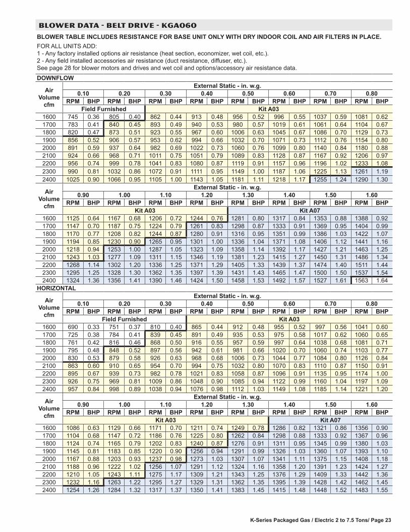
BLOWER DATA - BELT DRIVE - KGA060
BLOWER TABLE INCLUDES RESISTANCE FOR BASE UNIT ONLY WITH DRY INDOOR COIL AND AIR FILTERS IN PLACE.FOR ALL UNITS ADD: 1 - Any factory installed options air resistance (heat section, economizer, wet coil, etc.). 2 - Any field installed accessories air resistance (duct resistance, diffuser, etc.). See page 28 for blower motors and drives and wet coil and options/accessory air resistance data.
DOWNFLOW
Air Volume
cfm
External Static - in. w.g.0.10 0.20 0.30 0.40 0.50 0.60 0.70 0.80
RPM BHP RPM BHP RPM BHP RPM BHP RPM BHP RPM BHP RPM BHP RPM BHPField Furnished Kit A03
1600 745 0.36 805 0.40 862 0.44 913 0.48 956 0.52 996 0.55 1037 0.59 1081 0.621700 783 0.41 840 0.45 893 0.49 940 0.53 980 0.57 1019 0.61 1061 0.64 1104 0.671800 820 0.47 873 0.51 923 0.55 967 0.60 1006 0.63 1045 0.67 1086 0.70 1129 0.731900 856 0.52 906 0.57 953 0.62 994 0.66 1032 0.70 1071 0.73 1112 0.76 1154 0.802000 891 0.59 937 0.64 982 0.69 1022 0.73 1060 0.76 1099 0.80 1140 0.84 1180 0.882100 924 0.66 968 0.71 1011 0.75 1051 0.79 1089 0.83 1128 0.87 1167 0.92 1206 0.972200 956 0.74 999 0.78 1041 0.83 1080 0.87 1119 0.91 1157 0.96 1196 1.02 1233 1.082300 990 0.81 1032 0.86 1072 0.91 1111 0.95 1149 1.00 1187 1.06 1225 1.13 1261 1.192400 1025 0.90 1066 0.95 1105 1.00 1143 1.05 1181 1.11 1218 1.17 1255 1.24 1290 1.30
Air Volume
cfm
External Static - in. w.g.0.90 1.00 1.10 1.20 1.30 1.40 1.50 1.60
RPM BHP RPM BHP RPM BHP RPM BHP RPM BHP RPM BHP RPM BHP RPM BHPKit A03 Kit A07
1600 1125 0.64 1167 0.68 1206 0.72 1244 0.76 1281 0.80 1317 0.84 1353 0.88 1388 0.921700 1147 0.70 1187 0.75 1224 0.79 1261 0.83 1298 0.87 1333 0.91 1369 0.95 1404 0.991800 1170 0.77 1208 0.82 1244 0.87 1280 0.91 1316 0.95 1351 0.99 1386 1.03 1422 1.071900 1194 0.85 1230 0.90 1265 0.95 1301 1.00 1336 1.04 1371 1.08 1406 1.12 1441 1.162000 1218 0.94 1253 1.00 1287 1.05 1323 1.09 1358 1.14 1392 1.17 1427 1.21 1463 1.252100 1243 1.03 1277 1.09 1311 1.15 1346 1.19 1381 1.23 1415 1.27 1450 1.31 1486 1.342200 1268 1.14 1302 1.20 1336 1.25 1371 1.29 1405 1.33 1439 1.37 1474 1.40 1511 1.442300 1295 1.25 1328 1.30 1362 1.35 1397 1.39 1431 1.43 1465 1.47 1500 1.50 1537 1.542400 1324 1.36 1356 1.41 1390 1.46 1424 1.50 1458 1.53 1492 1.57 1527 1.61 1563 1.64
HORIZONTAL
Air Volume
cfm
External Static - in. w.g.0.10 0.20 0.30 0.40 0.50 0.60 0.70 0.80
RPM BHP RPM BHP RPM BHP RPM BHP RPM BHP RPM BHP RPM BHP RPM BHPField Furnished Kit A03
1600 690 0.33 751 0.37 810 0.40 865 0.44 912 0.48 955 0.52 997 0.56 1041 0.601700 725 0.38 784 0.41 839 0.45 891 0.49 935 0.53 975 0.58 1017 0.62 1060 0.651800 761 0.42 816 0.46 868 0.50 916 0.55 957 0.59 997 0.64 1038 0.68 1081 0.711900 795 0.48 848 0.52 897 0.56 942 0.61 981 0.66 1020 0.70 1060 0.74 1103 0.772000 830 0.53 879 0.58 926 0.63 968 0.68 1006 0.73 1044 0.77 1084 0.80 1126 0.842100 863 0.60 910 0.65 954 0.70 994 0.75 1032 0.80 1070 0.83 1110 0.87 1150 0.912200 895 0.67 939 0.73 982 0.78 1021 0.83 1058 0.87 1096 0.91 1135 0.95 1174 1.002300 926 0.75 969 0.81 1009 0.86 1048 0.90 1085 0.94 1122 0.99 1160 1.04 1197 1.092400 957 0.84 998 0.89 1038 0.94 1076 0.98 1112 1.03 1149 1.08 1185 1.14 1221 1.20
Air Volume
cfm
External Static - in. w.g.0.90 1.00 1.10 1.20 1.30 1.40 1.50 1.60
RPM BHP RPM BHP RPM BHP RPM BHP RPM BHP RPM BHP RPM BHP RPM BHPKit A03 Kit A07
1600 1086 0.63 1129 0.66 1171 0.70 1211 0.74 1249 0.78 1286 0.82 1321 0.86 1356 0.901700 1104 0.68 1147 0.72 1186 0.76 1225 0.80 1262 0.84 1298 0.88 1333 0.92 1367 0.961800 1124 0.74 1165 0.79 1202 0.83 1240 0.87 1276 0.91 1311 0.95 1345 0.99 1380 1.031900 1145 0.81 1183 0.85 1220 0.90 1256 0.94 1291 0.99 1326 1.03 1360 1.07 1393 1.102000 1167 0.88 1203 0.93 1237 0.98 1273 1.03 1307 1.07 1341 1.11 1375 1.15 1408 1.182100 1188 0.96 1222 1.02 1256 1.07 1291 1.12 1324 1.16 1358 1.20 1391 1.23 1424 1.272200 1210 1.05 1243 1.11 1275 1.17 1309 1.21 1343 1.25 1376 1.29 1409 1.33 1442 1.362300 1232 1.16 1263 1.22 1295 1.27 1329 1.31 1362 1.35 1395 1.39 1428 1.42 1462 1.452400 1254 1.26 1284 1.32 1317 1.37 1350 1.41 1383 1.45 1415 1.48 1448 1.52 1483 1.55
K-Series Packaged Gas / Electric 2 to 7.5 Tons / Page 24
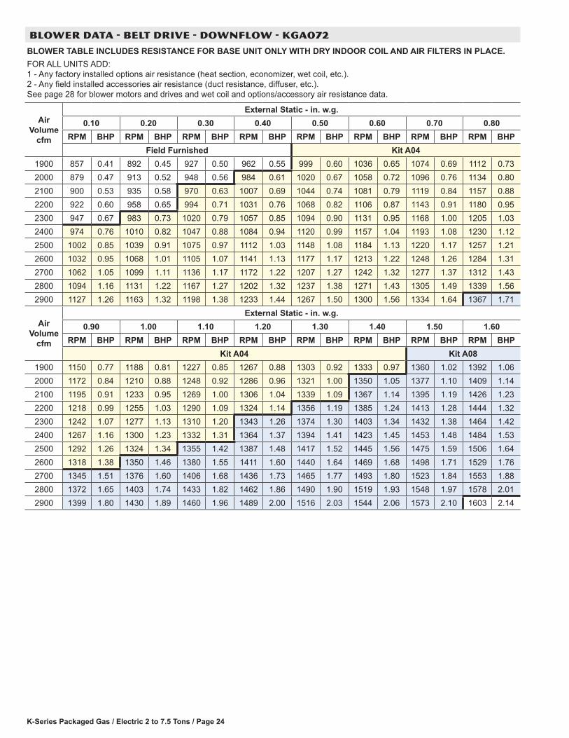
BLOWER DATA - BELT DRIVE - DOWNFLOW - KGA072
BLOWER TABLE INCLUDES RESISTANCE FOR BASE UNIT ONLY WITH DRY INDOOR COIL AND AIR FILTERS IN PLACE.FOR ALL UNITS ADD: 1 - Any factory installed options air resistance (heat section, economizer, wet coil, etc.). 2 - Any field installed accessories air resistance (duct resistance, diffuser, etc.). See page 28 for blower motors and drives and wet coil and options/accessory air resistance data.
Air Volume
cfm
External Static - in. w.g.0.10 0.20 0.30 0.40 0.50 0.60 0.70 0.80
RPM BHP RPM BHP RPM BHP RPM BHP RPM BHP RPM BHP RPM BHP RPM BHPField Furnished Kit A04
1900 857 0.41 892 0.45 927 0.50 962 0.55 999 0.60 1036 0.65 1074 0.69 1112 0.732000 879 0.47 913 0.52 948 0.56 984 0.61 1020 0.67 1058 0.72 1096 0.76 1134 0.802100 900 0.53 935 0.58 970 0.63 1007 0.69 1044 0.74 1081 0.79 1119 0.84 1157 0.882200 922 0.60 958 0.65 994 0.71 1031 0.76 1068 0.82 1106 0.87 1143 0.91 1180 0.952300 947 0.67 983 0.73 1020 0.79 1057 0.85 1094 0.90 1131 0.95 1168 1.00 1205 1.032400 974 0.76 1010 0.82 1047 0.88 1084 0.94 1120 0.99 1157 1.04 1193 1.08 1230 1.122500 1002 0.85 1039 0.91 1075 0.97 1112 1.03 1148 1.08 1184 1.13 1220 1.17 1257 1.212600 1032 0.95 1068 1.01 1105 1.07 1141 1.13 1177 1.17 1213 1.22 1248 1.26 1284 1.312700 1062 1.05 1099 1.11 1136 1.17 1172 1.22 1207 1.27 1242 1.32 1277 1.37 1312 1.432800 1094 1.16 1131 1.22 1167 1.27 1202 1.32 1237 1.38 1271 1.43 1305 1.49 1339 1.562900 1127 1.26 1163 1.32 1198 1.38 1233 1.44 1267 1.50 1300 1.56 1334 1.64 1367 1.71
Air Volume
cfm
External Static - in. w.g.0.90 1.00 1.10 1.20 1.30 1.40 1.50 1.60
RPM BHP RPM BHP RPM BHP RPM BHP RPM BHP RPM BHP RPM BHP RPM BHPKit A04 Kit A08
1900 1150 0.77 1188 0.81 1227 0.85 1267 0.88 1303 0.92 1333 0.97 1360 1.02 1392 1.062000 1172 0.84 1210 0.88 1248 0.92 1286 0.96 1321 1.00 1350 1.05 1377 1.10 1409 1.142100 1195 0.91 1233 0.95 1269 1.00 1306 1.04 1339 1.09 1367 1.14 1395 1.19 1426 1.232200 1218 0.99 1255 1.03 1290 1.09 1324 1.14 1356 1.19 1385 1.24 1413 1.28 1444 1.322300 1242 1.07 1277 1.13 1310 1.20 1343 1.26 1374 1.30 1403 1.34 1432 1.38 1464 1.422400 1267 1.16 1300 1.23 1332 1.31 1364 1.37 1394 1.41 1423 1.45 1453 1.48 1484 1.532500 1292 1.26 1324 1.34 1355 1.42 1387 1.48 1417 1.52 1445 1.56 1475 1.59 1506 1.642600 1318 1.38 1350 1.46 1380 1.55 1411 1.60 1440 1.64 1469 1.68 1498 1.71 1529 1.762700 1345 1.51 1376 1.60 1406 1.68 1436 1.73 1465 1.77 1493 1.80 1523 1.84 1553 1.882800 1372 1.65 1403 1.74 1433 1.82 1462 1.86 1490 1.90 1519 1.93 1548 1.97 1578 2.012900 1399 1.80 1430 1.89 1460 1.96 1489 2.00 1516 2.03 1544 2.06 1573 2.10 1603 2.14
K-Series Packaged Gas / Electric 2 to 7.5 Tons/ Page 25
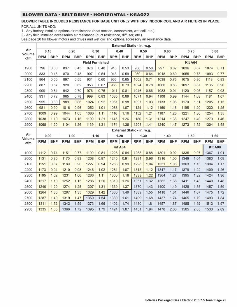
BLOWER DATA - BELT DRIVE - HORIZONTAL - KGA072
BLOWER TABLE INCLUDES RESISTANCE FOR BASE UNIT ONLY WITH DRY INDOOR COIL AND AIR FILTERS IN PLACE.FOR ALL UNITS ADD: 1 - Any factory installed options air resistance (heat section, economizer, wet coil, etc.). 2 - Any field installed accessories air resistance (duct resistance, diffuser, etc.). See page 28 for blower motors and drives and wet coil and options/accessory air resistance data.
Air Volume
cfm
External Static - in. w.g.0.10 0.20 0.30 0.40 0.50 0.60 0.70 0.80
RPM BHP RPM BHP RPM BHP RPM BHP RPM BHP RPM BHP RPM BHP RPM BHPField Furnished Kit A04
1900 796 0.38 837 0.43 878 0.48 918 0.53 958 0.58 997 0.62 1036 0.67 1074 0.712000 833 0.43 870 0.48 907 0.54 943 0.59 980 0.64 1018 0.69 1055 0.73 1093 0.772100 864 0.50 897 0.55 931 0.60 966 0.65 1002 0.71 1038 0.76 1075 0.80 1113 0.832200 887 0.57 920 0.62 953 0.67 988 0.73 1024 0.78 1060 0.83 1097 0.87 1135 0.902300 909 0.64 942 0.70 976 0.75 1011 0.81 1046 0.86 1083 0.91 1120 0.95 1157 0.982400 931 0.72 965 0.78 999 0.83 1035 0.89 1071 0.94 1108 0.99 1144 1.03 1181 1.072500 955 0.80 989 0.86 1024 0.92 1061 0.98 1097 1.03 1133 1.08 1170 1.11 1205 1.152600 981 0.90 1016 0.96 1052 1.01 1088 1.07 1124 1.12 1160 1.16 1195 1.20 1230 1.252700 1009 0.99 1044 1.05 1080 1.11 1116 1.16 1152 1.21 1187 1.26 1221 1.30 1254 1.352800 1038 1.10 1073 1.16 1109 1.21 1145 1.26 1180 1.31 1214 1.36 1247 1.40 1279 1.462900 1068 1.20 1104 1.26 1139 1.31 1174 1.36 1208 1.41 1240 1.47 1273 1.52 1304 1.58
Air Volume
cfm
External Static - in. w.g.0.90 1.00 1.10 1.20 1.30 1.40 1.50 1.60
RPM BHP RPM BHP RPM BHP RPM BHP RPM BHP RPM BHP RPM BHP RPM BHPKit A04 Kit A08
1900 1112 0.74 1151 0.77 1190 0.81 1228 0.84 1265 0.88 1301 0.92 1335 0.97 1367 1.012000 1131 0.80 1170 0.83 1208 0.87 1245 0.91 1281 0.96 1316 1.00 1349 1.04 1380 1.092100 1151 0.87 1189 0.90 1227 0.94 1263 0.99 1298 1.04 1331 1.08 1363 1.13 1394 1.172200 1173 0.94 1210 0.98 1246 1.02 1281 1.07 1315 1.12 1347 1.17 1379 1.22 1409 1.262300 1195 1.02 1231 1.06 1266 1.11 1300 1.16 1333 1.22 1364 1.27 1395 1.32 1424 1.362400 1217 1.10 1252 1.15 1286 1.20 1319 1.26 1351 1.32 1382 1.38 1411 1.43 1440 1.482500 1240 1.20 1274 1.25 1307 1.31 1339 1.37 1370 1.43 1400 1.49 1428 1.55 1457 1.592600 1264 1.30 1297 1.35 1329 1.42 1360 1.49 1389 1.55 1418 1.61 1446 1.67 1475 1.722700 1287 1.40 1319 1.47 1350 1.54 1380 1.61 1409 1.68 1437 1.74 1465 1.79 1493 1.842800 1311 1.52 1342 1.59 1373 1.66 1402 1.74 1430 1.8 1457 1.87 1485 1.92 1513 1.972900 1335 1.65 1366 1.72 1395 1.79 1424 1.87 1451 1.94 1478 2.00 1505 2.05 1533 2.09

K-Series Packaged Gas / Electric 2 to 7.5 Tons / Page 26
BLOWER DATA - BELT DRIVE - KGA090 - DOWNFLOW
BLOWER TABLE INCLUDES RESISTANCE FOR BASE UNIT ONLY WITH DRY INDOOR COIL AND AIR FILTERS IN PLACE.FOR ALL UNITS ADD: 1 - Any factory installed options air resistance (heat section, economizer, wet coil, etc.). 2 - Any field installed accessories air resistance (duct resistance, diffuser, etc.). See page 28 for blower motors and drives and wet coil and options/accessory air resistance data.
Air Volume
cfm
External Static - in. w.g.0.10 0.20 0.30 0.40 0.50 0.60 0.70 0.80 0.90 1.00
RPM BHP RPM BHP RPM BHP RPM BHP RPM BHP RPM BHP RPM BHP RPM BHP RPM BHP RPM BHPDrive Kit AA01 Drive Kit AA02 AA03
2400 621 0.71 652 0.76 684 0.81 716 0.86 746 0.92 776 0.97 805 1.02 830 1.08 855 1.14 879 1.192500 642 0.77 673 0.82 704 0.87 734 0.93 764 0.98 793 1.04 820 1.09 845 1.15 868 1.21 892 1.272600 665 0.82 694 0.88 724 0.93 753 0.99 782 1.05 810 1.11 835 1.17 859 1.23 883 1.29 907 1.342700 688 0.89 716 0.94 744 1.00 773 1.06 800 1.13 827 1.19 851 1.25 875 1.31 898 1.37 922 1.422800 710 0.95 738 1.02 765 1.08 792 1.15 818 1.21 844 1.28 868 1.34 891 1.40 914 1.45 938 1.512900 733 1.03 759 1.10 785 1.17 811 1.24 836 1.30 861 1.37 885 1.43 908 1.49 931 1.54 954 1.593000 754 1.12 779 1.19 805 1.26 830 1.33 855 1.40 879 1.46 902 1.52 925 1.58 948 1.63 970 1.693100 775 1.22 800 1.29 824 1.36 849 1.43 873 1.50 897 1.56 920 1.62 942 1.67 964 1.73 987 1.783200 796 1.32 820 1.39 844 1.47 868 1.53 892 1.60 915 1.66 937 1.72 959 1.77 981 1.83 1002 1.883300 816 1.43 840 1.50 863 1.57 887 1.64 910 1.70 933 1.76 955 1.82 976 1.88 997 1.93 1018 1.993400 837 1.54 860 1.61 883 1.68 906 1.75 929 1.81 951 1.87 972 1.93 993 1.98 1013 2.05 1033 2.113500 858 1.66 881 1.73 903 1.79 926 1.86 948 1.92 969 1.98 990 2.04 1009 2.10 1029 2.17 1048 2.243600 879 1.77 901 1.84 923 1.91 945 1.97 966 2.04 987 2.10 1006 2.16 1025 2.23 1044 2.30 1062 2.38
Air Volume
cfm
External Static - in. w.g.0.90 1.00 1.30 1.40 1.50 1.60 1.70 1.80 1.90 2.00
RPM BHP RPM BHP RPM BHP RPM BHP RPM BHP RPM BHP RPM BHP RPM BHP RPM BHP RPM BHPDrive Kit AA03 AA04
2400 904 1.25 929 1.29 956 1.34 982 1.39 1008 1.43 1032 1.49 1056 1.55 1078 1.62 1099 1.68 1121 1.752500 917 1.32 942 1.37 968 1.41 994 1.46 1020 1.51 1044 1.57 1066 1.64 1088 1.70 1108 1.77 1130 1.842600 931 1.39 957 1.44 982 1.49 1008 1.54 1032 1.60 1055 1.66 1077 1.73 1098 1.80 1118 1.87 1139 1.942700 946 1.47 971 1.52 996 1.57 1021 1.63 1045 1.69 1067 1.76 1088 1.83 1108 1.91 1127 1.98 1148 2.052800 962 1.56 986 1.61 1011 1.66 1034 1.72 1057 1.79 1079 1.86 1099 1.94 1118 2.02 1137 2.09 1158 2.162900 978 1.65 1001 1.70 1025 1.75 1048 1.82 1069 1.89 1090 1.98 1109 2.06 1128 2.14 1147 2.22 1167 2.283000 993 1.74 1016 1.79 1039 1.86 1061 1.93 1081 2.01 1101 2.10 1120 2.18 1138 2.27 1157 2.34 1177 2.413100 1009 1.84 1031 1.90 1052 1.97 1073 2.05 1093 2.13 1112 2.22 1130 2.31 1148 2.40 1167 2.47 1187 2.533200 1024 1.94 1045 2.01 1065 2.09 1085 2.17 1104 2.26 1123 2.36 1141 2.45 1159 2.53 1178 2.60 1198 2.663300 1038 2.06 1058 2.13 1078 2.22 1097 2.31 1116 2.40 1134 2.49 1152 2.58 1170 2.66 1189 2.73 1209 2.793400 1053 2.19 1072 2.27 1091 2.35 1109 2.45 1127 2.54 1145 2.63 1163 2.72 1181 2.79 1200 2.86 1220 2.923500 1067 2.32 1085 2.41 1103 2.50 1121 2.59 1138 2.69 1156 2.78 1174 2.85 1192 2.93 1212 2.99 1231 3.053600 1081 2.46 1098 2.55 1116 2.64 1133 2.74 1151 2.83 1168 2.91 1186 2.99 1205 3.06 1224 3.12 1243 3.17
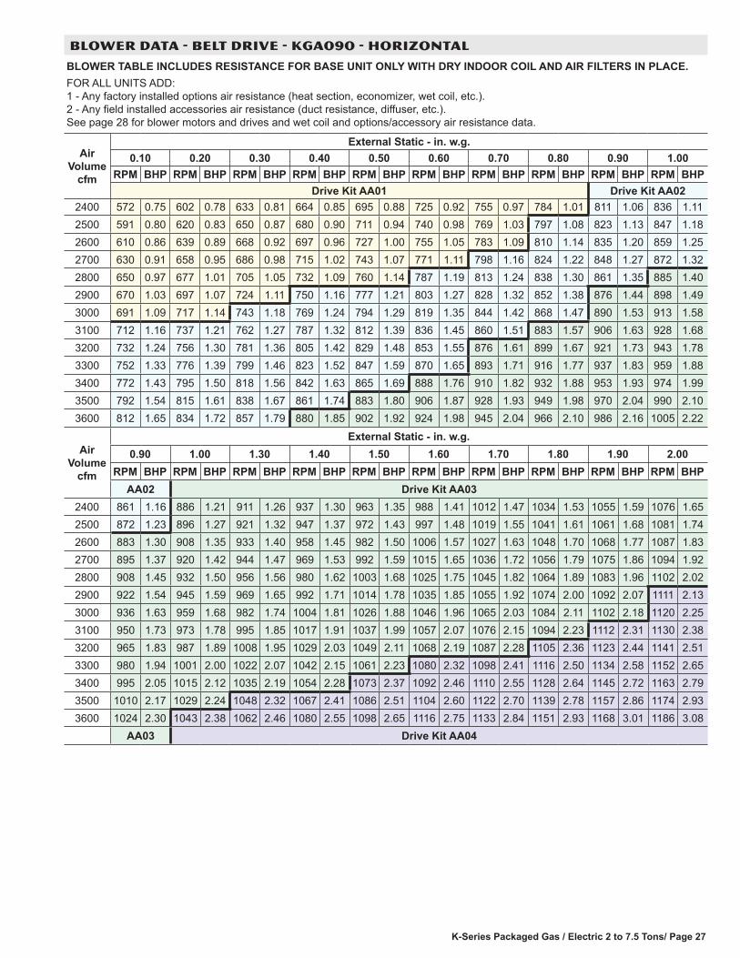
K-Series Packaged Gas / Electric 2 to 7.5 Tons/ Page 27
BLOWER DATA - BELT DRIVE - KGA090 - HORIZONTAL
BLOWER TABLE INCLUDES RESISTANCE FOR BASE UNIT ONLY WITH DRY INDOOR COIL AND AIR FILTERS IN PLACE.FOR ALL UNITS ADD: 1 - Any factory installed options air resistance (heat section, economizer, wet coil, etc.). 2 - Any field installed accessories air resistance (duct resistance, diffuser, etc.). See page 28 for blower motors and drives and wet coil and options/accessory air resistance data.
Air Volume
cfm
External Static - in. w.g.0.10 0.20 0.30 0.40 0.50 0.60 0.70 0.80 0.90 1.00
RPM BHP RPM BHP RPM BHP RPM BHP RPM BHP RPM BHP RPM BHP RPM BHP RPM BHP RPM BHPDrive Kit AA01 Drive Kit AA02
2400 572 0.75 602 0.78 633 0.81 664 0.85 695 0.88 725 0.92 755 0.97 784 1.01 811 1.06 836 1.112500 591 0.80 620 0.83 650 0.87 680 0.90 711 0.94 740 0.98 769 1.03 797 1.08 823 1.13 847 1.182600 610 0.86 639 0.89 668 0.92 697 0.96 727 1.00 755 1.05 783 1.09 810 1.14 835 1.20 859 1.252700 630 0.91 658 0.95 686 0.98 715 1.02 743 1.07 771 1.11 798 1.16 824 1.22 848 1.27 872 1.322800 650 0.97 677 1.01 705 1.05 732 1.09 760 1.14 787 1.19 813 1.24 838 1.30 861 1.35 885 1.402900 670 1.03 697 1.07 724 1.11 750 1.16 777 1.21 803 1.27 828 1.32 852 1.38 876 1.44 898 1.493000 691 1.09 717 1.14 743 1.18 769 1.24 794 1.29 819 1.35 844 1.42 868 1.47 890 1.53 913 1.583100 712 1.16 737 1.21 762 1.27 787 1.32 812 1.39 836 1.45 860 1.51 883 1.57 906 1.63 928 1.683200 732 1.24 756 1.30 781 1.36 805 1.42 829 1.48 853 1.55 876 1.61 899 1.67 921 1.73 943 1.783300 752 1.33 776 1.39 799 1.46 823 1.52 847 1.59 870 1.65 893 1.71 916 1.77 937 1.83 959 1.883400 772 1.43 795 1.50 818 1.56 842 1.63 865 1.69 888 1.76 910 1.82 932 1.88 953 1.93 974 1.993500 792 1.54 815 1.61 838 1.67 861 1.74 883 1.80 906 1.87 928 1.93 949 1.98 970 2.04 990 2.103600 812 1.65 834 1.72 857 1.79 880 1.85 902 1.92 924 1.98 945 2.04 966 2.10 986 2.16 1005 2.22
Air Volume
cfm
External Static - in. w.g.0.90 1.00 1.30 1.40 1.50 1.60 1.70 1.80 1.90 2.00
RPM BHP RPM BHP RPM BHP RPM BHP RPM BHP RPM BHP RPM BHP RPM BHP RPM BHP RPM BHPAA02 Drive Kit AA03
2400 861 1.16 886 1.21 911 1.26 937 1.30 963 1.35 988 1.41 1012 1.47 1034 1.53 1055 1.59 1076 1.652500 872 1.23 896 1.27 921 1.32 947 1.37 972 1.43 997 1.48 1019 1.55 1041 1.61 1061 1.68 1081 1.742600 883 1.30 908 1.35 933 1.40 958 1.45 982 1.50 1006 1.57 1027 1.63 1048 1.70 1068 1.77 1087 1.832700 895 1.37 920 1.42 944 1.47 969 1.53 992 1.59 1015 1.65 1036 1.72 1056 1.79 1075 1.86 1094 1.922800 908 1.45 932 1.50 956 1.56 980 1.62 1003 1.68 1025 1.75 1045 1.82 1064 1.89 1083 1.96 1102 2.022900 922 1.54 945 1.59 969 1.65 992 1.71 1014 1.78 1035 1.85 1055 1.92 1074 2.00 1092 2.07 1111 2.133000 936 1.63 959 1.68 982 1.74 1004 1.81 1026 1.88 1046 1.96 1065 2.03 1084 2.11 1102 2.18 1120 2.253100 950 1.73 973 1.78 995 1.85 1017 1.91 1037 1.99 1057 2.07 1076 2.15 1094 2.23 1112 2.31 1130 2.383200 965 1.83 987 1.89 1008 1.95 1029 2.03 1049 2.11 1068 2.19 1087 2.28 1105 2.36 1123 2.44 1141 2.513300 980 1.94 1001 2.00 1022 2.07 1042 2.15 1061 2.23 1080 2.32 1098 2.41 1116 2.50 1134 2.58 1152 2.653400 995 2.05 1015 2.12 1035 2.19 1054 2.28 1073 2.37 1092 2.46 1110 2.55 1128 2.64 1145 2.72 1163 2.793500 1010 2.17 1029 2.24 1048 2.32 1067 2.41 1086 2.51 1104 2.60 1122 2.70 1139 2.78 1157 2.86 1174 2.933600 1024 2.30 1043 2.38 1062 2.46 1080 2.55 1098 2.65 1116 2.75 1133 2.84 1151 2.93 1168 3.01 1186 3.08
AA03 Drive Kit AA04

K-Series Packaged Gas / Electric 2 to 7.5 Tons / Page 28
OPTIONS / ACCESSORIES AIR RESISTANCE FOR 024-072 MODELS - in. w.g. Air Volume
cfmWet Indoor Coil Gas Heat Economizer Filters
036-048 060 072 Medium Input High Input MERV 8 MERV 13800 0.01 0.01 0.01 0.02 0.02 0.04 0.04 0.05
1000 0.02 0.02 0.01 0.02 0.02 0.04 0.04 0.071200 0.03 0.04 0.02 0.02 0.02 0.04 0.04 0.071400 0.04 0.05 0.03 0.02 0.03 0.04 0.04 0.071600 0.05 0.06 0.04 0.03 0.04 0.04 0.04 0.071800 0.06 0.07 0.05 0.03 0.05 0.05 0.05 0.072000 0.08 0.09 0.06 0.04 0.06 0.05 0.05 0.082200 0.09 0.10 0.07 0.04 0.07 0.05 0.05 0.082400 0.10 0.12 0.08 0.05 0.08 0.05 0.05 0.082600 0.11 0.13 0.09 0.05 0.09 0.06 0.05 0.082800 0.13 0.15 0.10 0.06 0.10 0.06 0.05 0.083000 0.14 0.16 0.12 0.07 0.11 0.06 0.05 0.08
OPTIONS / ACCESSORIES AIR RESISTANCE FOR 090 MODELS - in. w.g. Air Volume
cfmWet Indoor Coil Gas Heat Economizer Filters
High Input MERV 8 MERV 132400 0.08 0.03 0.05 0.05 0.082600 0.09 0.04 0.06 0.05 0.082800 0.10 0.04 0.06 0.05 0.083000 0.11 0.04 0.06 0.05 0.083200 0.12 0.04 0.06 0.06 0.093400 0.14 0.05 0.06 0.06 0.093600 0.15 0.05 0.06 0.06 0.10
BLOWER DATA
BELT DRIVE KIT SPECIFICATIONS
Model No.Blower Motor Choice (HP)
Drive Kit No. RPM RangeNominal Maximum Nominal Maximum Nominal Maximum
036 1 1.15 1.5 1.7 2 2.3A01 673 - 1010 rpmA05 897 - 1346 rpm
048 1 1.15 1.5 1.7 2 2.3A02 745 - 1117 rpmA06 1071 - 1429 rpm
060 1 1.15 1.5 1.7 2 2.3A03 833 - 1250 rpmA07 1212 - 1548 rpm
072 1 1.15 - - - - - - 2 2.3A04 968 - 1340 rpmA08 1193 - 1591 rpm
090
1 1.15 - - - - - - - - - - - - AA01 522 - 784 rpm
2 2.3 - - - - - - - - - - - -AA02 632 - 875 rpmAA03 798 - 1105 rpm
3 3.45 - - - - - - - - - - - - AA04 921 - 1228 rpmNOTE - Using total air volume and system static pressure requirements determine from blower performance tables rpm and motor hp required. Maximum usable hp of motors furnished are shown. In Canada, nominal motor hp is also maximum usable motor hp. If motors of comparable hp are used, be sure to keep within the service factor limitations outlined on the motor nameplate.
POWER EXHAUST FAN PERFORMANCE Return Air System Static
Pressure - in. w.g. Air Volume Exhausted
cfm0.00 20000.05 19900.10 19240.15 18100.20 16640.25 15070.30 13500.35 1210
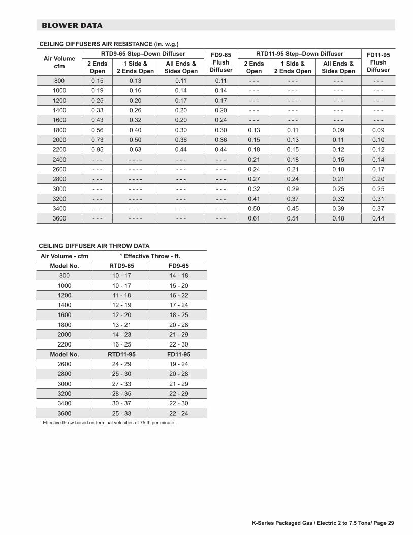
K-Series Packaged Gas / Electric 2 to 7.5 Tons/ Page 29
BLOWER DATA
CEILING DIFFUSERS AIR RESISTANCE (in. w.g.)
Air Volume cfm
RTD9-65 Step–Down Diffuser FD9-65 Flush
Diffuser
RTD11-95 Step–Down Diffuser FD11-95 Flush
Diffuser2 Ends Open
1 Side & 2 Ends Open
All Ends & Sides Open
2 Ends Open
1 Side & 2 Ends Open
All Ends & Sides Open
800 0.15 0.13 0.11 0.11 - - - - - - - - - - - -1000 0.19 0.16 0.14 0.14 - - - - - - - - - - - -1200 0.25 0.20 0.17 0.17 - - - - - - - - - - - -1400 0.33 0.26 0.20 0.20 - - - - - - - - - - - -1600 0.43 0.32 0.20 0.24 - - - - - - - - - - - -1800 0.56 0.40 0.30 0.30 0.13 0.11 0.09 0.092000 0.73 0.50 0.36 0.36 0.15 0.13 0.11 0.102200 0.95 0.63 0.44 0.44 0.18 0.15 0.12 0.122400 - - - - - - - - - - - - - 0.21 0.18 0.15 0.142600 - - - - - - - - - - - - - 0.24 0.21 0.18 0.172800 - - - - - - - - - - - - - 0.27 0.24 0.21 0.203000 - - - - - - - - - - - - - 0.32 0.29 0.25 0.253200 - - - - - - - - - - - - - 0.41 0.37 0.32 0.313400 - - - - - - - - - - - - - 0.50 0.45 0.39 0.373600 - - - - - - - - - - - - - 0.61 0.54 0.48 0.44
CEILING DIFFUSER AIR THROW DATAAir Volume - cfm 1 Effective Throw - ft.
Model No. RTD9-65 FD9-65800 10 - 17 14 - 18
1000 10 - 17 15 - 201200 11 - 18 16 - 221400 12 - 19 17 - 241600 12 - 20 18 - 251800 13 - 21 20 - 282000 14 - 23 21 - 292200 16 - 25 22 - 30
Model No. RTD11-95 FD11-952600 24 - 29 19 - 242800 25 - 30 20 - 283000 27 - 33 21 - 293200 28 - 35 22 - 293400 30 - 37 22 - 303600 25 - 33 22 - 24
1 Effective throw based on terminal velocities of 75 ft. per minute.

K-Series Packaged Gas / Electric 2 to 7.5 Tons / Page 30
ELECTRICAL DATA 2 - 2.5 TONDIRECT DRIVE BLOWER KGA024S KGA030S1 Voltage - 60hz 208/230V - 1 Ph 208/230V - 1 PhCompressor 1 Rated Load Amps 13.5 14.1
Locked Rotor Amps
58.3 73
Outdoor Fan Motors (1)
Full Load Amps (total)
1.7 1.7
Service Outlet 115V GFI (amps) 15 15Indoor Blower Motor
Horsepower .25 .25Full Load Amps 1.8 1.8
2 Maximum Overcurrent Protection
Unit Only 30 35
3 Minimum Circuit Ampacity
Unit Only 21 22
ELECTRICAL ACCESSORIESDisconnect Kit
Standard Access 20W17 20W17Hinged Access 20W23 20W23
NOTE - All units have a minimum Short Circuit Current Rating (SCCR) of 5000 amps. 1 Extremes of operating range are plus and minus 10% of line voltage.2 HACR type breaker or fuse.3 Refer to National or Canadian Electrical Code manual to determine wire, fuse and disconnect size requirements.
ELECTRICAL DATA 3 TONKGA036S1 Voltage - 60hz 208/230V - 1 Ph 208/230V - 3 Ph 460V - 3 Ph 575V - 3 PhCompressor 1 Rated Load Amps 16.7 10.4 5.8 3.8
Locked Rotor Amps 79 73 38 36.5Outdoor Fan Motors (1)
Full Load Amps (total) 1.7 1.7 1.1 0.7
Power Exhaust (1) 0.33 HP
Full Load Amps (total) 2.4 2.4 1.3 1
Service Outlet 115V GFI (amps) 15 15 15 20Indoor Blower Motor
Horsepower .5 1.5 .5 1 2 .5 1 2 .5 1 2Full Load Amps 3.9 11 3.9 4.6 7.5 2 2.1 3.4 2 1.7 2.7
2 Maximum Overcurrent Protection
Unit Only 40 50 25 25 30 15 15 15 15 15 15with (1) 0.33 HP Power Exhaust
45 50 30 30 35 15 15 15 15 15 15
3 Minimum Circuit Ampacity
Unit Only 27 34 19 20 23 11 11 12 8 8 9with (1) 0.33 HP Power Exhaust
29 36 21 22 25 12 12 14 9 9 10
ELECTRICAL ACCESSORIESDisconnect Kit
Standard Access 20W17 20W17 20W17 20W17Hinged Access 20W23 20W23 20W23 20W23
NOTE - All units have a minimum Short Circuit Current Rating (SCCR) of 5000 amps. 1 Extremes of operating range are plus and minus 10% of line voltage.2 HACR type breaker or fuse.3 Refer to National or Canadian Electrical Code manual to determine wire, fuse and disconnect size requirements.
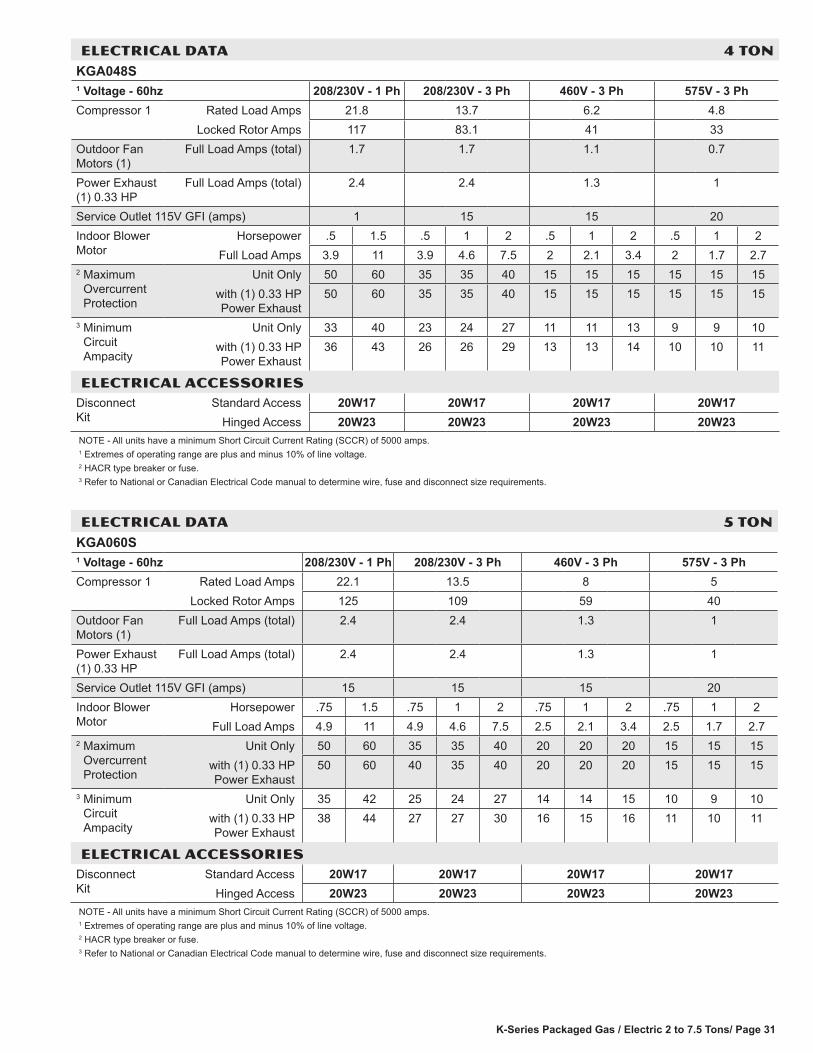
K-Series Packaged Gas / Electric 2 to 7.5 Tons/ Page 31
ELECTRICAL DATA 4 TONKGA048S1 Voltage - 60hz 208/230V - 1 Ph 208/230V - 3 Ph 460V - 3 Ph 575V - 3 PhCompressor 1 Rated Load Amps 21.8 13.7 6.2 4.8
Locked Rotor Amps 117 83.1 41 33Outdoor Fan Motors (1)
Full Load Amps (total) 1.7 1.7 1.1 0.7
Power Exhaust (1) 0.33 HP
Full Load Amps (total) 2.4 2.4 1.3 1
Service Outlet 115V GFI (amps) 1 15 15 20Indoor Blower Motor
Horsepower .5 1.5 .5 1 2 .5 1 2 .5 1 2Full Load Amps 3.9 11 3.9 4.6 7.5 2 2.1 3.4 2 1.7 2.7
2 Maximum Overcurrent Protection
Unit Only 50 60 35 35 40 15 15 15 15 15 15with (1) 0.33 HP Power Exhaust
50 60 35 35 40 15 15 15 15 15 15
3 Minimum Circuit Ampacity
Unit Only 33 40 23 24 27 11 11 13 9 9 10with (1) 0.33 HP Power Exhaust
36 43 26 26 29 13 13 14 10 10 11
ELECTRICAL ACCESSORIESDisconnect Kit
Standard Access 20W17 20W17 20W17 20W17Hinged Access 20W23 20W23 20W23 20W23
NOTE - All units have a minimum Short Circuit Current Rating (SCCR) of 5000 amps. 1 Extremes of operating range are plus and minus 10% of line voltage.2 HACR type breaker or fuse.3 Refer to National or Canadian Electrical Code manual to determine wire, fuse and disconnect size requirements.
ELECTRICAL DATA 5 TONKGA060S1 Voltage - 60hz 208/230V - 1 Ph 208/230V - 3 Ph 460V - 3 Ph 575V - 3 PhCompressor 1 Rated Load Amps 22.1 13.5 8 5
Locked Rotor Amps 125 109 59 40Outdoor Fan Motors (1)
Full Load Amps (total) 2.4 2.4 1.3 1
Power Exhaust (1) 0.33 HP
Full Load Amps (total) 2.4 2.4 1.3 1
Service Outlet 115V GFI (amps) 15 15 15 20Indoor Blower Motor
Horsepower .75 1.5 .75 1 2 .75 1 2 .75 1 2Full Load Amps 4.9 11 4.9 4.6 7.5 2.5 2.1 3.4 2.5 1.7 2.7
2 Maximum Overcurrent Protection
Unit Only 50 60 35 35 40 20 20 20 15 15 15with (1) 0.33 HP Power Exhaust
50 60 40 35 40 20 20 20 15 15 15
3 Minimum Circuit Ampacity
Unit Only 35 42 25 24 27 14 14 15 10 9 10with (1) 0.33 HP Power Exhaust
38 44 27 27 30 16 15 16 11 10 11
ELECTRICAL ACCESSORIESDisconnect Kit
Standard Access 20W17 20W17 20W17 20W17Hinged Access 20W23 20W23 20W23 20W23
NOTE - All units have a minimum Short Circuit Current Rating (SCCR) of 5000 amps. 1 Extremes of operating range are plus and minus 10% of line voltage.2 HACR type breaker or fuse.3 Refer to National or Canadian Electrical Code manual to determine wire, fuse and disconnect size requirements.

K-Series Packaged Gas / Electric 2 to 7.5 Tons / Page 32
ELECTRICAL DATA 6 TONKGA072S1 Voltage - 60hz 208/230V - 3 Ph 460V - 3 Ph 575V - 3 PhCompressor 1 Rated Load Amps 19 9.7 7.4
Locked Rotor Amps 123 62 50Outdoor Fan Motors (1)
Full Load Amps (total) 2.4 1.3 1
Power Exhaust (1) 0.33 HP
Full Load Amps (total) 2.4 1.3 1
Service Outlet 115V GFI (amps) 15 15 20Indoor Blower Motor
Horsepower 1 2 1 2 1 2Full Load Amps 4.6 7.5 2.1 3.4 1.7 2.7
2 Maximum Overcurrent Protection
Unit Only 45 50 25 25 15 20with (1) 0.33 HP Power Exhaust
50 50 25 25 20 20
3 Minimum Circuit Ampacity
Unit Only 31 34 16 17 12 13with (1) 0.33 HP Power Exhaust
34 37 17 19 13 14
ELECTRICAL ACCESSORIESDisconnect Kit
Standard Access 20W20 20W20 20W20Hinged Access 20W26 20W26 20W26
NOTE - All units have a minimum Short Circuit Current Rating (SCCR) of 5000 amps. 1 Extremes of operating range are plus and minus 10% of line voltage.2 HACR type breaker or fuse.3 Refer to National or Canadian Electrical Code manual to determine wire, fuse and disconnect size requirements.
ELECTRICAL DATA 7.5 TONKGA090S1 Voltage - 60hz 208/230V - 3 Ph 460V - 3 Ph 575V - 3 PhCompressor 1 Rated Load Amps 25 12.2 9
Locked Rotor Amps 164 100 78Outdoor Fan Motors (1)
Full Load Amps (total) 2.4 1.3 1
Power Exhaust (1) 0.33 HP
Full Load Amps (total) 2.4 1.3 1
Service Outlet 115V GFI 15 15 20Indoor Blower Motor
Horsepower 1 2 3 1 2 3 1 2 3Full Load Amps 4.6 7.5 10.6 2.1 3.4 4.8 1.7 2.7 3.9
2 Maximum Overcurrent Protection
Unit Only 60 60 60 30 30 30 20 20 25with (1) 0.33 HP Power Exhaust
60 60 70 30 30 30 20 20 25
3 Minimum Circuit Ampacity
Unit Only 39 42 45 19 20 22 14 15 17with (1) 0.33 HP Power Exhaust
41 44 47 20 22 23 15 16 18
ELECTRICAL ACCESSORIESDisconnect Kit
Standard Access 20W20 20W20 20W20Hinged Access 20W26 20W26 20W26
NOTE - All units have a minimum Short Circuit Current Rating (SCCR) of 5000 amps. 1 Extremes of operating range are plus and minus 10% of line voltage.2 HACR type breaker or fuse.3 Refer to National or Canadian Electrical Code manual to determine wire, fuse and disconnect size requirements.

K-Series Packaged Gas / Electric 2 to 7.5 Tons/ Page 33
B
D
C
A
OUTDOOR AIRHOOD
1 Unit ClearanceA B C D Top
Clearancein. mm in. mm in. mm in. mmService Clearance 48 1219 36 914 36 914 36 914Clearance to Combustibles 36 914 1 25 1 25 1 25
UnobstructedMinimum Operation Clearance 36 914 36 914 36 914 36 914NOTE - Entire perimeter of unit base requires support when elevated above the mounting surface.1 Service Clearance - Required for removal of serviceable parts.
Clearance to Combustibles - Required clearance to combustible material. Minimum Operation Clearance - Required clearance for proper unit operation.
UNIT CLEARANCES - INCHES (MM)

K-Series Packaged Gas / Electric 2 to 7.5 Tons / Page 34
OUTDOOR SOUND DATA Unit
Model No.Octave Band Linear Sound Power Levels dB, re 10-12 Watts - Center Frequency - Hz 1 Sound Rating
Number (SRN) (dBA)
125 250 500 1000 2000 4000 8000
024, 030, 036 and 048 63 66 70 71 68 62 53 75060 and 072 67 72 77 76 73 68 61 82090 66 71 73 74 70 65 57 79Note - The octave sound power data does not include tonal corrections.1 Sound Rating Number according to ARI Standard 270-95 (includes pure tone penalty). “SRN” is the overall A-Weighted Sound Power Level, (LWA), dB (100 Hz to
10,000 Hz).
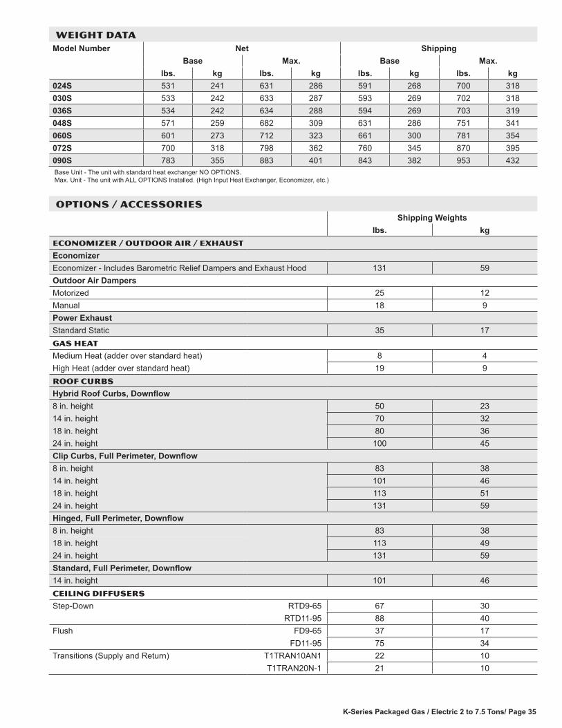
K-Series Packaged Gas / Electric 2 to 7.5 Tons/ Page 35
WEIGHT DATAModel Number Net Shipping
Base Max. Base Max.lbs. kg lbs. kg lbs. kg lbs. kg
024S 531 241 631 286 591 268 700 318030S 533 242 633 287 593 269 702 318036S 534 242 634 288 594 269 703 319048S 571 259 682 309 631 286 751 341060S 601 273 712 323 661 300 781 354072S 700 318 798 362 760 345 870 395090S 783 355 883 401 843 382 953 432Base Unit - The unit with standard heat exchanger NO OPTIONS. Max. Unit - The unit with ALL OPTIONS Installed. (High Input Heat Exchanger, Economizer, etc.)
OPTIONS / ACCESSORIESShipping Weights
lbs. kgECONOMIZER / OUTDOOR AIR / EXHAUST
EconomizerEconomizer - Includes Barometric Relief Dampers and Exhaust Hood 131 59Outdoor Air DampersMotorized 25 12Manual 18 9Power ExhaustStandard Static 35 17GAS HEAT
Medium Heat (adder over standard heat) 8 4High Heat (adder over standard heat) 19 9ROOF CURBS
Hybrid Roof Curbs, Downflow8 in. height 50 2314 in. height 70 3218 in. height 80 3624 in. height 100 45Clip Curbs, Full Perimeter, Downflow8 in. height 83 3814 in. height 101 4618 in. height 113 5124 in. height 131 59Hinged, Full Perimeter, Downflow8 in. height 83 3818 in. height 113 4924 in. height 131 59Standard, Full Perimeter, Downflow14 in. height 101 46CEILING DIFFUSERS
Step-Down RTD9-65 67 30RTD11-95 88 40
Flush FD9-65 37 17FD11-95 75 34
Transitions (Supply and Return) T1TRAN10AN1 22 10T1TRAN20N-1 21 10
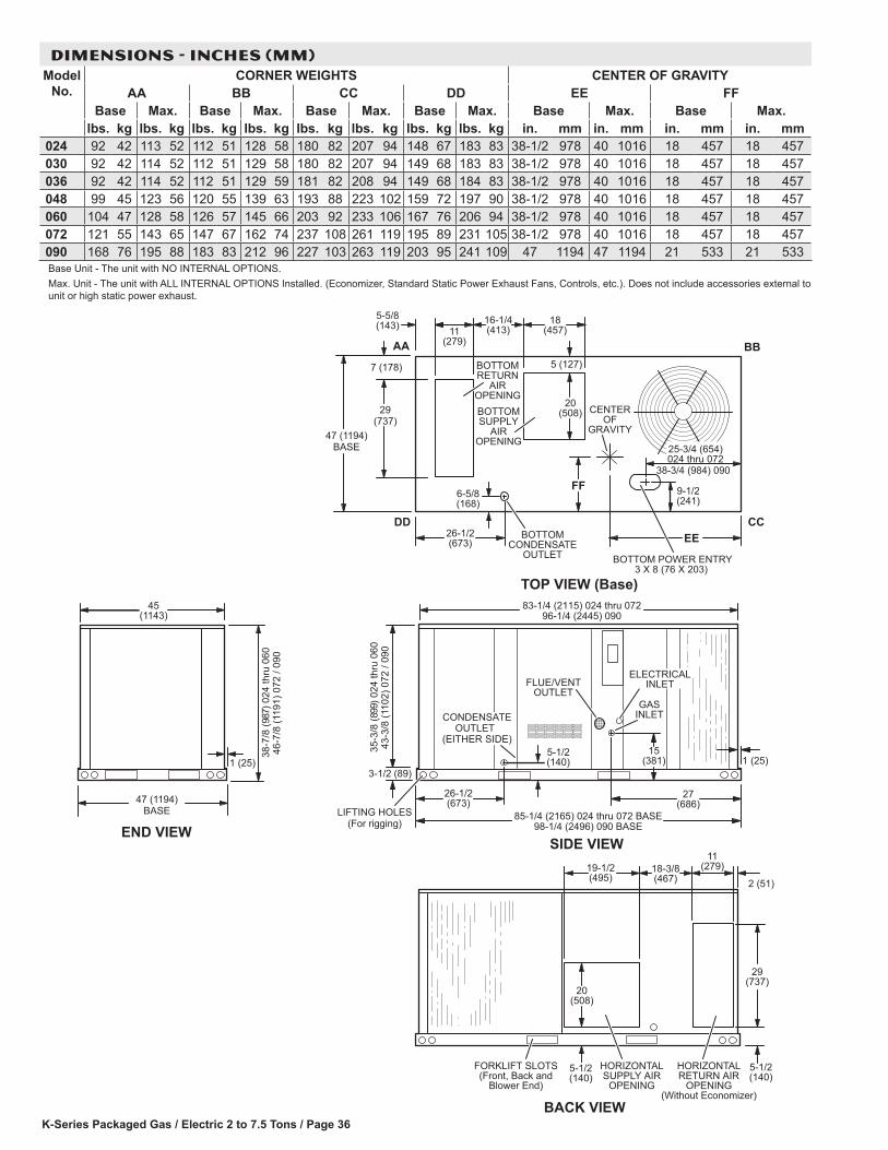
K-Series Packaged Gas / Electric 2 to 7.5 Tons / Page 36
45(1143)
END VIEW
1 (25)
47 (1194)BASE
38-7
/8 (9
87) 0
24 th
ru 0
6046
-7/8
(119
1) 0
72 /
090
18-3/8(467)
19-1/2(495)
5-1/2(140)
FORKLIFT SLOTS(Front, Back and
Blower End)
HORIZONTALRETURN AIR
OPENING(Without Economizer)
HORIZONTALSUPPLY AIR
OPENING
2 (51)
(279)
29(737)
20(508)
5-1/2(140)
BACK VIEW
11
DD CC
BBAA
FF
EE
11(279)
16-1/4(413)
18(457)
20(508)
5 (127)
47 (1194)BASE
BOTTOMSUPPLY
AIROPENING
TOP VIEW (Base)
CENTEROF
GRAVITY
9-1/2(241)
6-5/8(168)
26-1/2(673)
5-5/8(143)
29(737)
7 (178) BOTTOMRETURN
AIROPENING
BOTTOMCONDENSATE
OUTLET BOTTOM POWER ENTRY3 X 8 (76 X 203)
25-3/4 (654)024 thru 072
38-3/4 (984) 090
GASINLET
FLUE/VENTOUTLET
27(686)
15(381)
3-1/2 (89)
98-1/4 (2496) 090 BASE
26-1/2(673)
5-1/2(140)
LIFTING HOLES(For rigging)
SIDE VIEW
1 (25)
35-3
/8 (8
99) 0
24 th
ru 0
6043
-3/8
(110
2) 0
72 /
090
85-1/4 (2165) 024 thru 072 BASE
96-1/4 (2445) 09083-1/4 (2115) 024 thru 072
CONDENSATEOUTLET
(EITHER SIDE)
ELECTRICALINLET
DIMENSIONS - INCHES (MM)Model
No.CORNER WEIGHTS CENTER OF GRAVITY
AA BB CC DD EE FFBase Max. Base Max. Base Max. Base Max. Base Max. Base Max.
lbs. kg lbs. kg lbs. kg lbs. kg lbs. kg lbs. kg lbs. kg lbs. kg in. mm in. mm in. mm in. mm024 92 42 113 52 112 51 128 58 180 82 207 94 148 67 183 83 38-1/2 978 40 1016 18 457 18 457030 92 42 114 52 112 51 129 58 180 82 207 94 149 68 183 83 38-1/2 978 40 1016 18 457 18 457036 92 42 114 52 112 51 129 59 181 82 208 94 149 68 184 83 38-1/2 978 40 1016 18 457 18 457048 99 45 123 56 120 55 139 63 193 88 223 102 159 72 197 90 38-1/2 978 40 1016 18 457 18 457060 104 47 128 58 126 57 145 66 203 92 233 106 167 76 206 94 38-1/2 978 40 1016 18 457 18 457072 121 55 143 65 147 67 162 74 237 108 261 119 195 89 231 105 38-1/2 978 40 1016 18 457 18 457090 168 76 195 88 183 83 212 96 227 103 263 119 203 95 241 109 47 1194 47 1194 21 533 21 533Base Unit - The unit with NO INTERNAL OPTIONS.Max. Unit - The unit with ALL INTERNAL OPTIONS Installed. (Economizer, Standard Static Power Exhaust Fans, Controls, etc.). Does not include accessories external to unit or high static power exhaust.
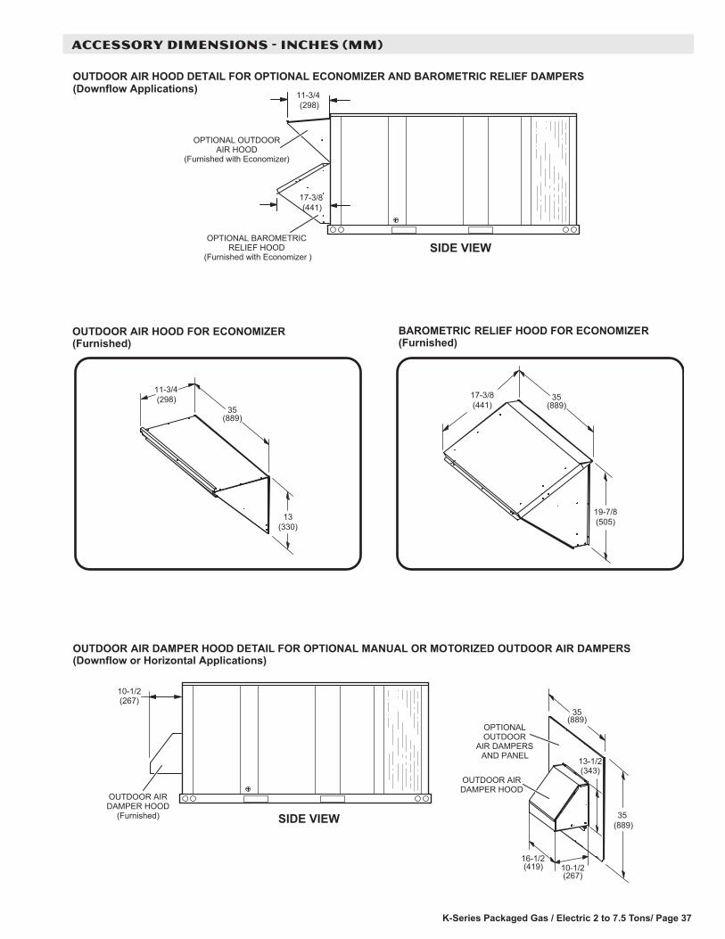
K-Series Packaged Gas / Electric 2 to 7.5 Tons/ Page 37
ACCESSORY DIMENSIONS - INCHES (MM)
OUTDOOR AIR HOOD DETAIL FOR OPTIONAL ECONOMIZER AND BAROMETRIC RELIEF DAMPERS(Downflow Applications)
OPTIONAL OUTDOORAIR HOOD
(Furnished with Economizer)
OPTIONAL BAROMETRICRELIEF HOOD
(Furnished with Economizer )
17-3/8 (441)
13(330)
11-3/4 (298)
35(889)
19-7/8(505)
17-3/8(441)
BAROMETRIC RELIEF HOOD FOR ECONOMIZER(Furnished)
OUTDOOR AIR HOOD FOR ECONOMIZER(Furnished)
OUTDOOR AIR DAMPER HOOD DETAIL FOR OPTIONAL MANUAL OR MOTORIZED OUTDOOR AIR DAMPERS(Downflow or Horizontal Applications)
10-1/2(267)
OUTDOOR AIRDAMPER HOOD
(Furnished)
16-1/2(419)
OUTDOOR AIRDAMPER HOOD
35(889)
13-1/2(343)
10-1/2(267)
SIDE VIEW
11-3/4 (298)
SIDE VIEW
35(889)
OPTIONALOUTDOOR
AIR DAMPERSAND PANEL
35 (889)

K-Series Packaged Gas / Electric 2 to 7.5 Tons / Page 38
2-1/4(57)
UNIT RETURN AIR DUCTOPENING WITH ECONOMIZER
INSTALLED
30-7/16(773)
7/8(22)
18-3/4 (476)
END VIEW
7/8(22)
2-1/4(57)
OUTDOOR AIR HOOD DETAIL WITH OPTIONAL ECONOMIZER AND BAROMETRIC RELIEF DAMPERS(Horizontal Applications)
NOTE - Return Air Duct and Transition must be supported.
BAROMETRIC RELIEF HOOD DIMENSIONSWidth - 35-1/2 in. (902 mm)Height -21 in. (533 mm)
See previous page for details.
and
Dam
pers
SUPPLY AIR DUCT(Field Provided)
RETURN AIR DUCT(Field Fabricated - Must be sized to
accommodate Barometric ReliefHood and Return Air Requirements)
TOP VIEW
Baro
met
ric R
elie
f Hoo
d
RETURN AIRDUCT TRANSITION(Field fabricated and
installed on unit)
ECONOMIZER DAMPERS
RETURNAIR
INLET
SUPPLYAIR
OUTLET
RETURN AIR DUCT INLET(Field Fabricated - Must be sized to
accommodate Barometric ReliefHood and Return Air Requirements)
5-1/2(140)
19-1/2(495)
BAROMETRIC RELIEF HOOD(Furnished with Economizer andField Installed on Field fabricated
Return Air Duct)
RETURN AIRDUCT TRANSITION(Field fabricated and
installed on unit)
31-3/8(797)
11-3/4 (298)
OUTDOOR AIR HOOD(Furnished with Economizer)
BACK VIEW
EXHAUSTAIR
OUTDOORAIR
HORIZONTALSUPPLY AIR
OPENING
HORIZONTALRETURN AIR
OPENING
This openingnot used inHorizontal
Applicationswith
Economizer20(508)
NOTE - Horizontal applications with Economizer require Horizontal Economizer Conversion Kit.See Options/Accessories table.
ACCESSORY DIMENSIONS - INCHES (MM)
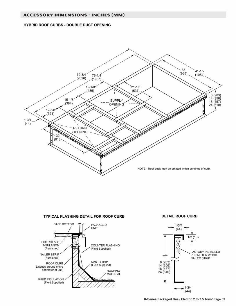
K-Series Packaged Gas / Electric 2 to 7.5 Tons/ Page 39
NOTE - Roof deck may be omitted within confines of curb.
TYPICAL FLASHING DETAIL FOR ROOF CURB
ROOF CURB(Extends around entire
perimeter of unit)
FIBERGLASSINSULATION
(Furnished)COUNTER FLASHING(Field Supplied)
BASE BOTTOM
RIGID INSULATION(Field Supplied)
ROOFINGMATERIAL
CANT STRIP(Field Supplied)
PACKAGEDUNIT
NAILER STRIP(Furnished)
DETAIL ROOF CURB
FACTORY INSTALLEDPERIMETER WOODNAILER STRIP
RETURNOPENING
SUPPLYOPENING
HYBRID ROOF CURBS - DOUBLE DUCT OPENING
79-3/4(2026)
76-1/4(1937)
19-1/8(486)
15-1/8(384)
12-5/8(321)
1-3/4(44)
32(813)
21-1/8(537)
41-1/2(1054)
38(965)
8 (203)14 (356)18 (457)24 (610)
8 (203)14 (356)18 (457)24 (610)
1-3/4(44)
1/2 (13)
1-3/4(44)
ACCESSORY DIMENSIONS - INCHES (MM)

K-Series Packaged Gas / Electric 2 to 7.5 Tons / Page 40
ACCESSORY DIMENSIONS - INCHES (MM)
TYPICAL FLASHING DETAIL FOR ROOF CURB
ROOF CURB(Extends around entire
perimeter of unit)
FIBERGLASSINSULATION
(Furnished)COUNTER FLASHING(Field Supplied)
BASE BOTTOM
RIGID INSULATION(Field Supplied)
ROOFINGMATERIAL
CANT STRIP(Field Supplied)
PACKAGEDUNIT
NAILER STRIP(Furnished)
CLIP CURBS - FULL PERIMETER - DOUBLE DUCT OPENING (090 MODELS ONLY)
12-5/8(321)
41-1/2(1054)21-1/8
(537)
19-1/8(486)
15-1/8
8 (203)14 (356)18 (457)24 (610)
(384)
32(813)
37-7/8(962)
1-13/16(46)
1-13/16(46)
RETURNOPENING
SUPPLYOPENING
NOTE - Roof deck may be omitted within confines of curb.
42-1/4(1073)
92-3/4(2356)
89-1/8(2264)
DETAIL ROOF CURB
FACTORY INSTALLEDPERIMETER WOODNAILER STRIP
1-13/16(46)
1-13/16(46)
1/2 (13)
8 (203)14 (356)18 (457)24 (610)

K-Series Packaged Gas / Electric 2 to 7.5 Tons/ Page 41
ACCESSORY DIMENSIONS - INCHES (MM)
HINGED ROOF CURBS - FULL PERIMETER - DOUBLE DUCT OPENING (090 MODELS ONLY)
TYPICAL FLASHING DETAIL FOR ROOF CURB
ROOF CURB(Extends around entire
perimeter of unit)
FIBERGLASSINSULATION
(Furnished)COUNTER FLASHING(Field Supplied)
BASE BOTTOM
RIGID INSULATION(Field Supplied)
ROOFINGMATERIAL
CANT STRIP(Field Supplied)
PACKAGEDUNIT
NAILER STRIP(Furnished)
DETAIL ROOF CURB
FACTORY INSTALLEDPERIMETER WOODNAILER STRIP
1-13/16(46)
1-13/16(46)
1/2 (13)
8 (203)18 (457)24 (610)
12-5/8(321)
41-1/2(1054)21-1/8
(537)
19-1/8
8 (203)18 (457)24 (610)
(486)
15-1/8(384)
32(813)
37-7/8(962)
1-13/16(46)
1-13/16(46)
RETURNOPENING
SUPPLYOPENING
NOTE - Roof deck may be omitted within confines of curb.
42-1/4(1073)
92-3/4(2356)
89-1/8(2264)
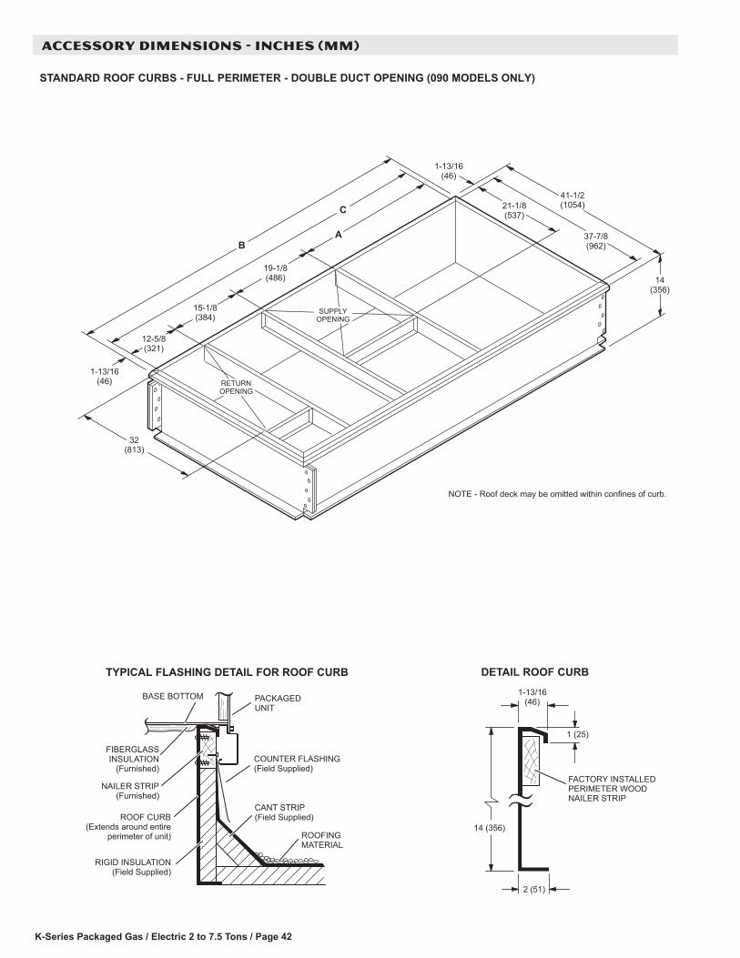
K-Series Packaged Gas / Electric 2 to 7.5 Tons / Page 42
ACCESSORY DIMENSIONS - INCHES (MM)
STANDARD ROOF CURBS - FULL PERIMETER - DOUBLE DUCT OPENING (090 MODELS ONLY)
TYPICAL FLASHING DETAIL FOR ROOF CURB
ROOF CURB(Extends around entire
perimeter of unit)
FIBERGLASSINSULATION
(Furnished)COUNTER FLASHING(Field Supplied)
BASE BOTTOM
RIGID INSULATION(Field Supplied)
ROOFINGMATERIAL
CANT STRIP(Field Supplied)
PACKAGEDUNIT
NAILER STRIP(Furnished)
1-13/16(46)
DETAIL ROOF CURB
14 (356)
1 (25)
FACTORY INSTALLEDPERIMETER WOODNAILER STRIP
2 (51)
1-13/16(46)
12-5/8(321)
B
41-1/2(1054)21-1/8
(537)
19-1/8(486)
15-1/8(384)
32(813)
14(356)
37-7/8(962)
1-13/16(46)
SUPPLYOPENING
RETURNOPENING
NOTE - Roof deck may be omitted within confines of curb.
C
A
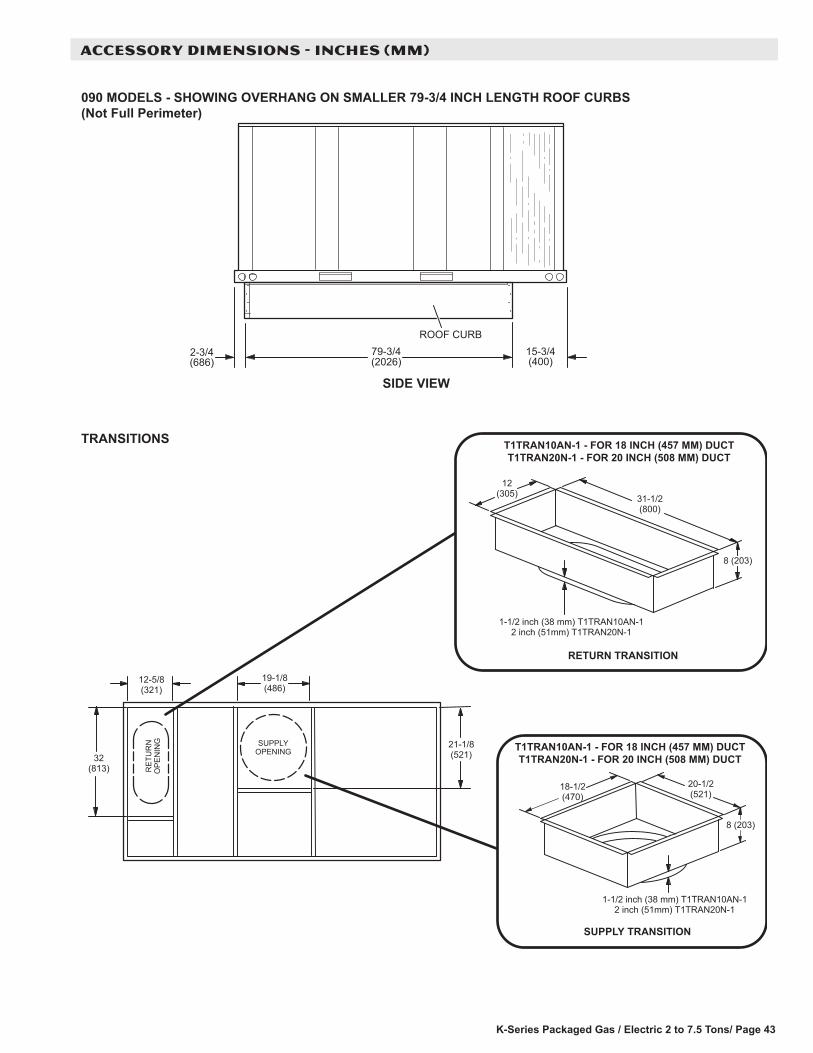
K-Series Packaged Gas / Electric 2 to 7.5 Tons/ Page 43
ACCESSORY DIMENSIONS - INCHES (MM)
090 MODELS - SHOWING OVERHANG ON SMALLER 79-3/4 INCH LENGTH ROOF CURBS(Not Full Perimeter)
79-3/4(2026)
15-3/4(400)
2-3/4(686)
SIDE VIEW
ROOF CURB
RE
TUR
NO
PE
NIN
G
12(305) 31-1/2
(800)
8 (203)
18-1/2(470)
20-1/2(521)
8 (203)
RETURN TRANSITION
SUPPLY TRANSITION
TRANSITIONS
21-1/8(521)
SUPPLYOPENING
32(813)
T1TRAN10AN-1 - FOR 18 INCH (457 MM) DUCTT1TRAN20N-1 - FOR 20 INCH (508 MM) DUCT
T1TRAN10AN-1 - FOR 18 INCH (457 MM) DUCTT1TRAN20N-1 - FOR 20 INCH (508 MM) DUCT
12-5/8(321)
19-1/8(486)
1-1/2 inch (38 mm) T1TRAN10AN-12 inch (51mm) T1TRAN20N-1
1-1/2 inch (38 mm) T1TRAN10AN-12 inch (51mm) T1TRAN20N-1

K-Series Packaged Gas / Electric 2 to 7.5 Tons / Page 44
ACCESSORY DIMENSIONS - INCHES (MM)
COMBINATION CEILING SUPPLY AND RETURN DIFFUSERSSTEP-DOWN CEILING DIFFUSER FLUSH CEILING DIFFUSER
L A
J
C
HH
DG
G
FE
B
K
2 (51)
A
C
HH
DG
G
FE
B
2 (51)
Model Number RTD9-65 RTD11-95A in. 47-5/8 47-5/8
mm 1159 1159B in. 23-5/8 29-5/8
mm 600 752C in. 11-3/8 14-3/8
mm 289 365D in. 21-1/2 27-1/2
mm 546 699E in. 45-1/2 45-1/2
mm 1156 1158F in. 22-1/2 22-1/2
mm 572 572G in. 11-1/2 11-1/2
mm 292 292H in. 10-3/4 13-3/4
mm 273 349J in. 45-1/2 45-1/2
mm 1156 1156K in. 21-1/2 27-1/2
mm 546 699L in. 7-1/8 8-1/8
mm 181 206Duct Size in. 18 round 20 round
mm 457 round 508 round
Model Number FD9-65 FD11-95A in. 47-5/8 47-5/8
mm 1159 1159B in. 23-5/8 29-5/8
mm 600 752C in. 13-1/2 16-5/8
mm 343 422D in. 21 27
mm 533 686E in. 45 45
mm 1143 1143F in. 22-1/2 22-1/2
mm 572 572G in. 11-1/4 11-1/4
mm 286 286H in. 10-1/2 13-1/2
mm 267 343Duct Size in. 18 round 20 round
mm 457 round 508 round


REVISIONS
Section Description
Options/AccessoriesRemoved larger accessories (Economizers, Power Exhaust, Outdoor Air Dampers, Barometric Relief Dampers) for 072/090 models. All sizes now use the same accessories.
NOTE - Due to Allied Commercial ongoing commitment to quality, Specifications, Ratings and Dimensions subject to change without notice and without incurring liability. Improper installation, adjustment, alteration, service or maintenance can cause property damage or personal injury. Installation and service must be performed by a qualified installer and servicing agency.
©2013 Allied Air Enterprises LLC, a Lennox International Inc. Company
Visit us at www.allied-commercial.com
For the latest technical information, visit us at www.allied-commercial.com
Contact us at 1-800-448-5872