asyncronous sequential analysis
TRANSCRIPT
7/28/2019 ASYNCRONOUS SEQUENTIAL ANALYSIS
http://slidepdf.com/reader/full/asyncronous-sequential-analysis 1/23
UNIVERSITY OF KWAZULU-NATAL DIGITAL ELECTRONICS SERIES
ASYNCHRONOUS SEQUENTIAL
CIRCUITS-ANALYSIS
DR T WALINGO
LECTURE 6
1
7/28/2019 ASYNCRONOUS SEQUENTIAL ANALYSIS
http://slidepdf.com/reader/full/asyncronous-sequential-analysis 2/23
UNIVERSITY OF KWAZULU-NATAL DIGITAL ELECTRONICS SERIES
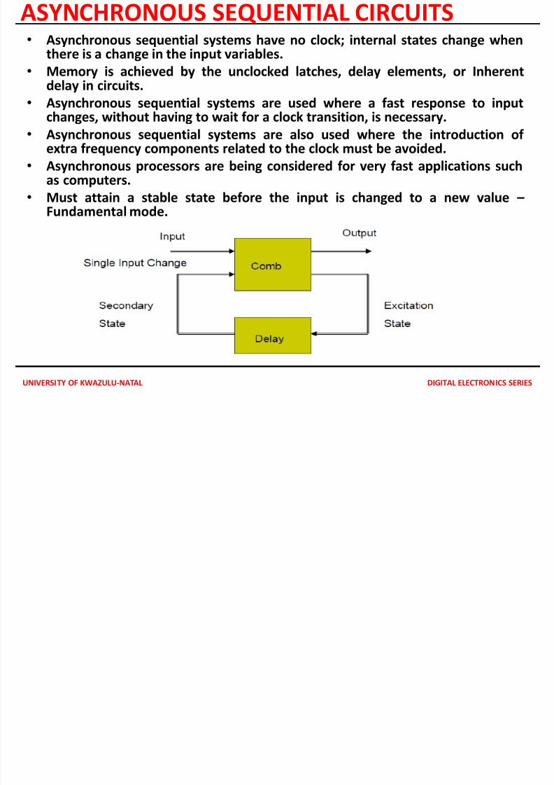
ASYNCHRONOUS SEQUENTIAL CIRCUITS• Asynchronous sequential systems have no clock; internal states change when
there is a change in the input variables.
• Memory is achieved by the unclocked latches, delay elements, or Inherent
delay in circuits.• Asynchronous sequential systems are used where a fast response to input
changes, without having to wait for a clock transition, is necessary.
• Asynchronous sequential systems are also used where the introduction of extra frequency components related to the clock must be avoided.
• Asynchronous processors are being considered for very fast applications such
as computers.• Must attain a stable state before the input is changed to a new value –
Fundamental mode.
7/28/2019 ASYNCRONOUS SEQUENTIAL ANALYSIS
http://slidepdf.com/reader/full/asyncronous-sequential-analysis 3/23
UNIVERSITY OF KWAZULU-NATAL DIGITAL ELECTRONICS SERIES
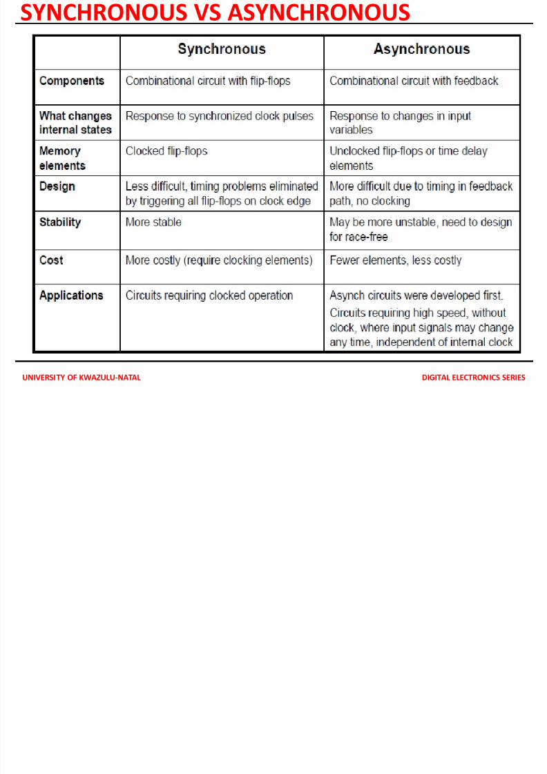
SYNCHRONOUS VS ASYNCHRONOUS
7/28/2019 ASYNCRONOUS SEQUENTIAL ANALYSIS
http://slidepdf.com/reader/full/asyncronous-sequential-analysis 4/23
UNIVERSITY OF KWAZULU-NATAL DIGITAL ELECTRONICS SERIES
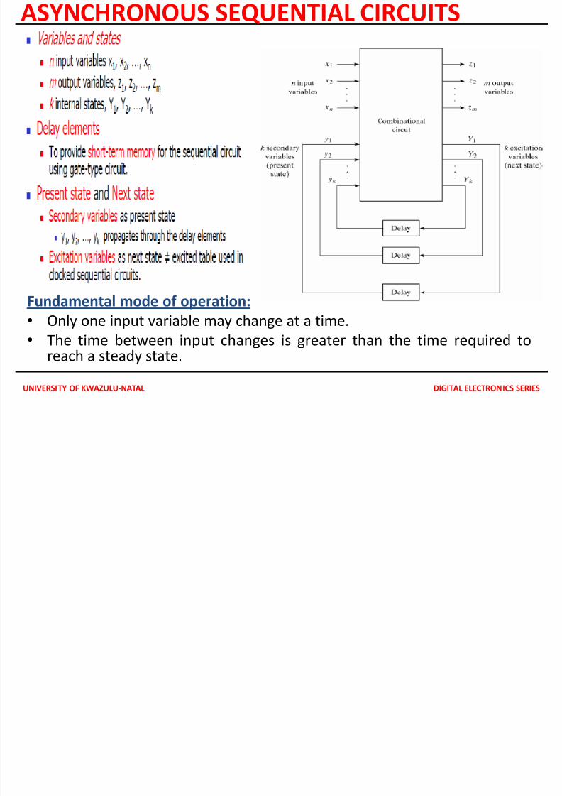
ASYNCHRONOUS SEQUENTIAL CIRCUITS
Fundamental mode of operation:
• Only one input variable may change at a time.
• The time between input changes is greater than the time required toreach a steady state.
7/28/2019 ASYNCRONOUS SEQUENTIAL ANALYSIS
http://slidepdf.com/reader/full/asyncronous-sequential-analysis 5/23
UNIVERSITY OF KWAZULU-NATAL DIGITAL ELECTRONICS SERIES
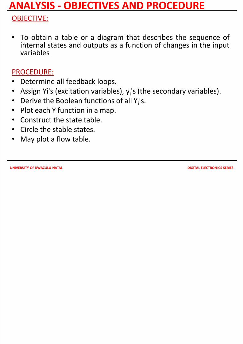
ANALYSIS - OBJECTIVES AND PROCEDUREOBJECTIVE:
•
To obtain a table or a diagram that describes the sequence of internal states and outputs as a function of changes in the inputvariables
PROCEDURE:
• Determine all feedback loops.• Assign Yi's (excitation variables), yi's (the secondary variables).
• Derive the Boolean functions of all Yi's.
• Plot each Y function in a map.
•Construct the state table.
• Circle the stable states.
• May plot a flow table.
7/28/2019 ASYNCRONOUS SEQUENTIAL ANALYSIS
http://slidepdf.com/reader/full/asyncronous-sequential-analysis 6/23
UNIVERSITY OF KWAZULU-NATAL DIGITAL ELECTRONICS SERIES
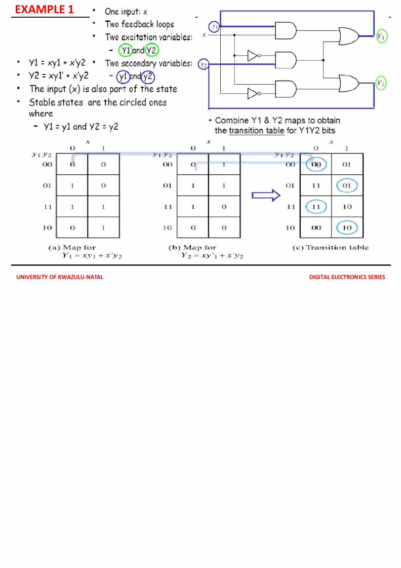
EXAMPLE 1
7/28/2019 ASYNCRONOUS SEQUENTIAL ANALYSIS
http://slidepdf.com/reader/full/asyncronous-sequential-analysis 7/23UNIVERSITY OF KWAZULU-NATAL DIGITAL ELECTRONICS SERIES
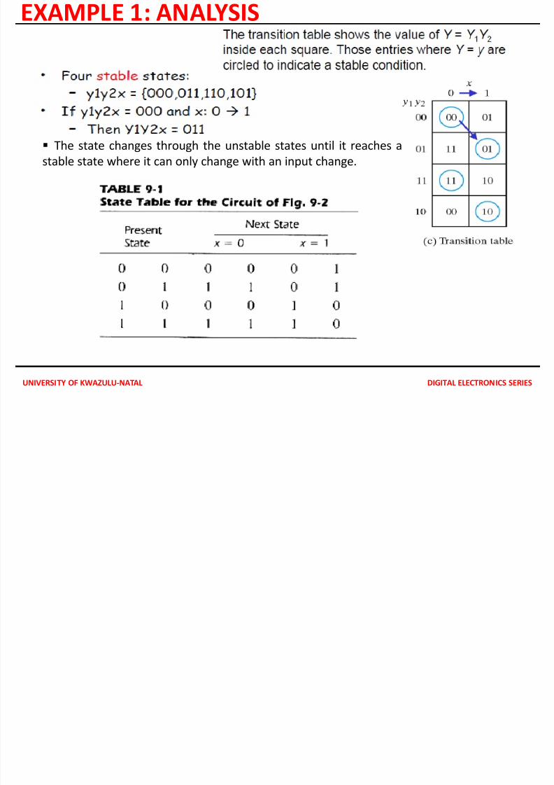
EXAMPLE 1: ANALYSIS
The state changes through the unstable states until it reaches a
stable state where it can only change with an input change.
7/28/2019 ASYNCRONOUS SEQUENTIAL ANALYSIS
http://slidepdf.com/reader/full/asyncronous-sequential-analysis 8/23UNIVERSITY OF KWAZULU-NATAL DIGITAL ELECTRONICS SERIES
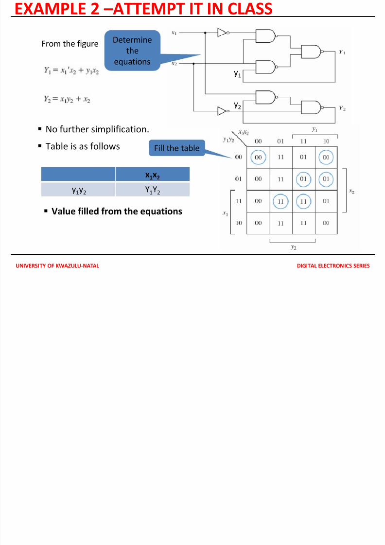
EXAMPLE 2 –ATTEMPT IT IN CLASS
No further simplification.
Table is as follows
x1x2
y1y2 Y1Y2
Value filled from the equations
From the figure
y1
y2
Determine
the
equations
Fill the table
7/28/2019 ASYNCRONOUS SEQUENTIAL ANALYSIS
http://slidepdf.com/reader/full/asyncronous-sequential-analysis 9/23UNIVERSITY OF KWAZULU-NATAL DIGITAL ELECTRONICS SERIES
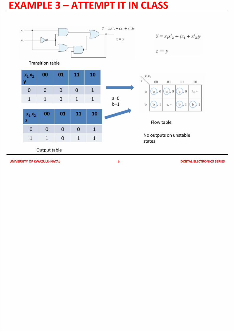
EXAMPLE 3 – ATTEMPT IT IN CLASS
9
x1
x2y
00 01 11 10
0 0 0 0 1
1 1 0 1 1
x1
x2
z
00 01 11 10
0 0 0 0 1
1 1 0 1 1
a=0
b=1
Transition table
Output table
Flow table
No outputs on unstable
states
7/28/2019 ASYNCRONOUS SEQUENTIAL ANALYSIS
http://slidepdf.com/reader/full/asyncronous-sequential-analysis 10/23UNIVERSITY OF KWAZULU-NATAL DIGITAL ELECTRONICS SERIES
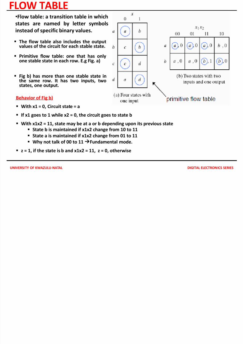
FLOW TABLE
The flow table also includes the outputvalues of the circuit for each stable state.
Primitive flow table: one that has onlyone stable state in each row. E.g Fig. a)
Fig b) has more than one stable state in
the same row. It has two inputs, twostates, one output.
Behavior of Fig b)
With x1 = 0, Circuit state = a
If x1 goes to 1 while x2 = 0, the circuit goes to state b
With x1x2 = 11, state may be at a or b depending upon its previous state
State b is maintained if x1x2 change from 10 to 11
State a is maintained if x1x2 change from 01 to 11
Why not talk of 00 to 11Fundamental mode.
z = 1, if the state is b and x1x2 = 11, z = 0, otherwise
•Flow table: a transition table in which
states are named by letter symbols
instead of specific binary values.
7/28/2019 ASYNCRONOUS SEQUENTIAL ANALYSIS
http://slidepdf.com/reader/full/asyncronous-sequential-analysis 11/23UNIVERSITY OF KWAZULU-NATAL DIGITAL ELECTRONICS SERIES
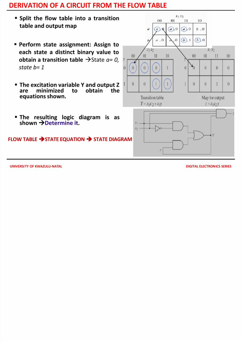
DERIVATION OF A CIRCUIT FROM THE FLOW TABLE
FLOW TABLESTATE EQUATION STATE DIAGRAM
Perform state assignment: Assign to
each state a distinct binary value to
obtain a transition table State a= 0,
state b= 1
The excitation variable Y and output Zare minimized to obtain theequations shown.
The resulting logic diagram is asshownDetermine it.
Split the flow table into a transition
table and output map
RACE CONDITION
7/28/2019 ASYNCRONOUS SEQUENTIAL ANALYSIS
http://slidepdf.com/reader/full/asyncronous-sequential-analysis 12/23UNIVERSITY OF KWAZULU-NATAL DIGITAL ELECTRONICS SERIES
RACE CONDITION• Occurs when two or more binary variables change value in
response to a change in an input variable.
• When unequal delays are encountered, a race condition maycause the state variables to change in an unpredictable manner.
• Example to change from 00 → 11, due to unequal delay we canhave – 00 → 10 → 11
– 00 → 01 → 11
• The order by which the state variables change may not beknown in advance.
Two types:
• Noncritical race: The final stable state the circuit reached does
not depend on the order in which the state variables change.• Critical race: End up in two or more different stable states
depending on the order in which the state variables change.
NON CRITICAL RACES
7/28/2019 ASYNCRONOUS SEQUENTIAL ANALYSIS
http://slidepdf.com/reader/full/asyncronous-sequential-analysis 13/23UNIVERSITY OF KWAZULU-NATAL DIGITAL ELECTRONICS SERIES
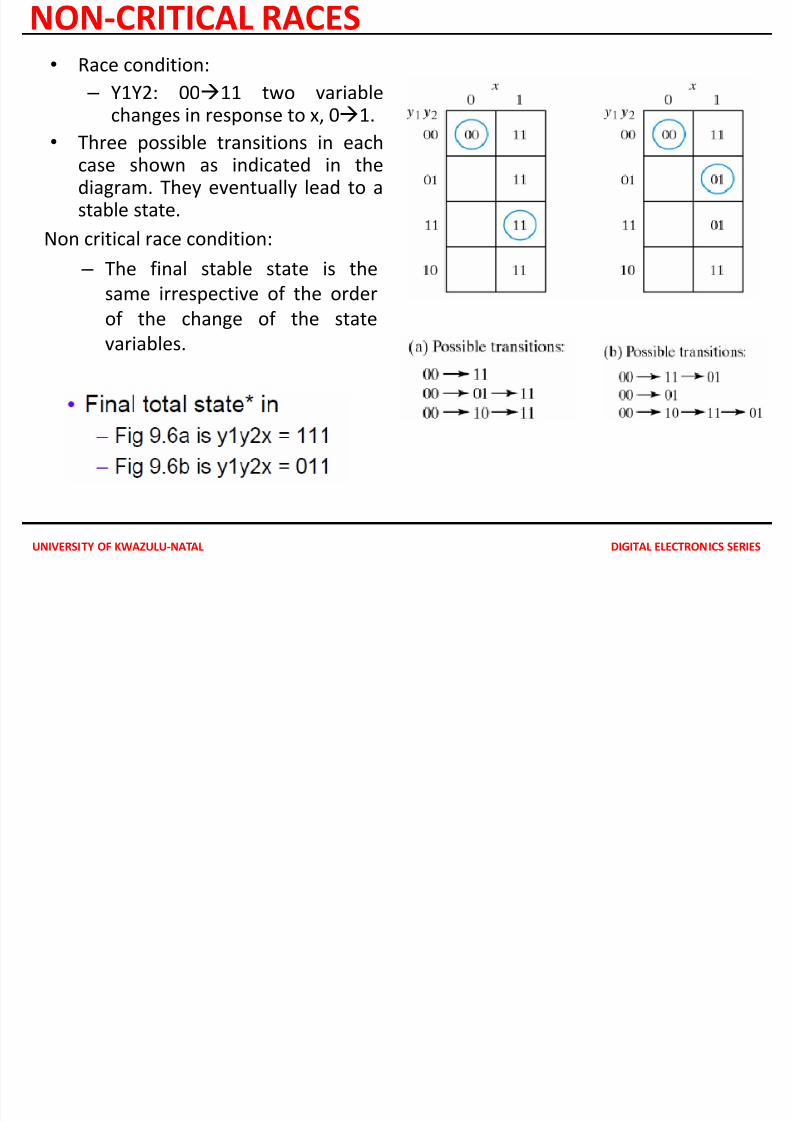
NON-CRITICAL RACES
• Race condition:
– Y1Y2: 0011 two variablechanges in response to x, 01.
• Three possible transitions in eachcase shown as indicated in thediagram. They eventually lead to astable state.
Non critical race condition:
– The final stable state is thesame irrespective of the order
of the change of the state
variables.
CRITICAL RACES
7/28/2019 ASYNCRONOUS SEQUENTIAL ANALYSIS
http://slidepdf.com/reader/full/asyncronous-sequential-analysis 14/23UNIVERSITY OF KWAZULU-NATAL DIGITAL ELECTRONICS SERIES
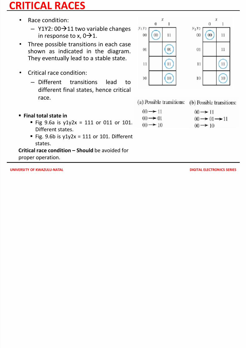
CRITICAL RACES
Final total state in
Fig 9.6a is y1y2x = 111 or 011 or 101.Different states.
Fig. 9.6b is y1y2x = 111 or 101. Different
states.
Critical race condition – Should be avoided for
proper operation.
• Race condition:
– Y1Y2: 0011 two variable changesin response to x, 01.
• Three possible transitions in each caseshown as indicated in the diagram.They eventually lead to a stable state.
• Critical race condition:
– Different transitions lead todifferent final states, hence critical
race.
CYCLES
7/28/2019 ASYNCRONOUS SEQUENTIAL ANALYSIS
http://slidepdf.com/reader/full/asyncronous-sequential-analysis 15/23UNIVERSITY OF KWAZULU-NATAL DIGITAL ELECTRONICS SERIES
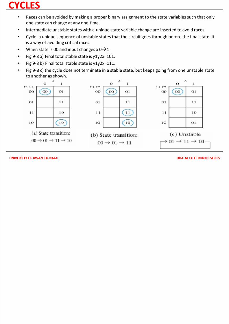
CYCLES• Races can be avoided by making a proper binary assignment to the state variables such that only
one state can change at any one time.
• Intermediate unstable states with a unique state variable change are inserted to avoid races.
•
Cycle: a unique sequence of unstable states that the circuit goes through before the final state. Itis a way of avoiding critical races.
• When state is 00 and input changes x 01
• Fig 9-8 a) Final total stable state is y1y2x=101.
• Fig 9-8 b) Final total stable state is y1y2x=111.
• Fig 9-8 c) the cycle does not terminate in a stable state, but keeps going from one unstable state
to another as shown.
STABILITY CONSIDERATIONS
7/28/2019 ASYNCRONOUS SEQUENTIAL ANALYSIS
http://slidepdf.com/reader/full/asyncronous-sequential-analysis 16/23
UNIVERSITY OF KWAZULU-NATAL DIGITAL ELECTRONICS SERIES
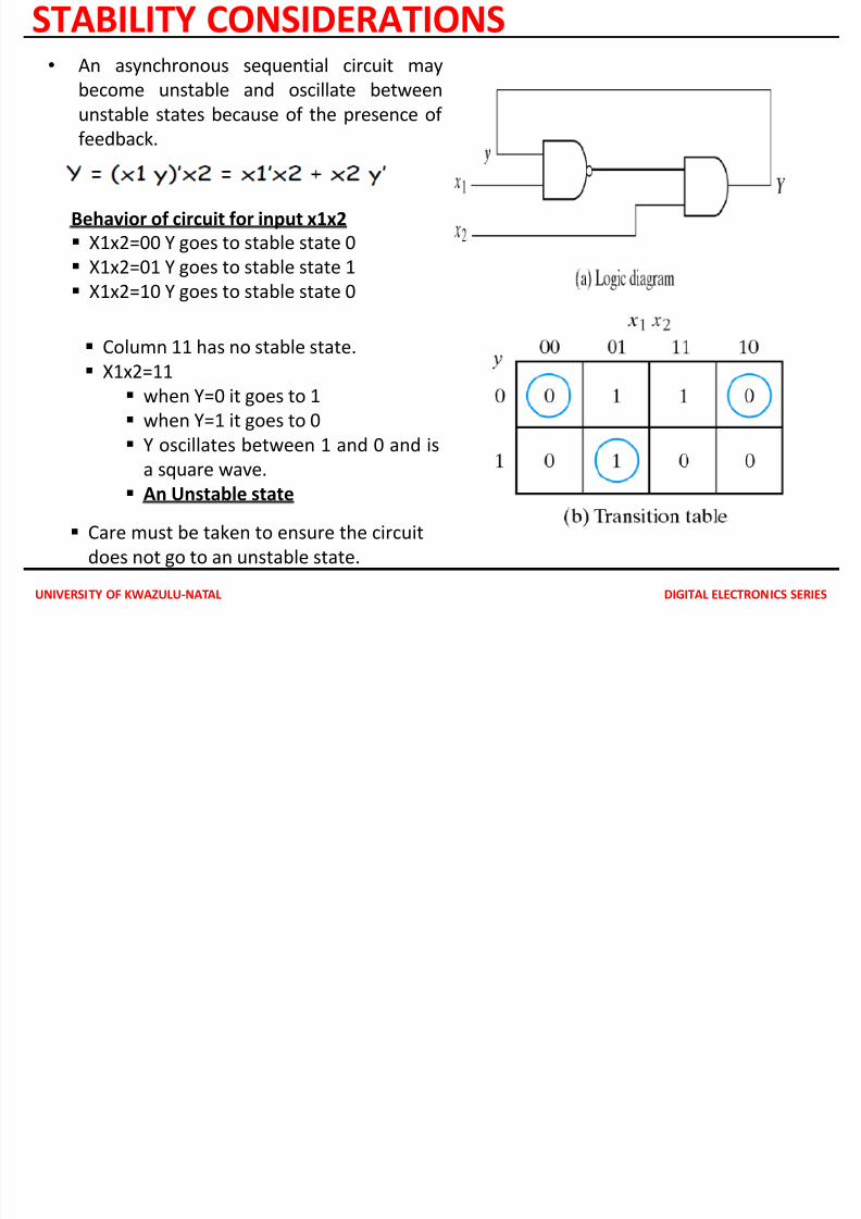
STABILITY CONSIDERATIONS
Behavior of circuit for input x1x2
X1x2=00 Y goes to stable state 0
X1x2=01 Y goes to stable state 1
X1x2=10 Y goes to stable state 0
Care must be taken to ensure the circuit
does not go to an unstable state.
• An asynchronous sequential circuit may
become unstable and oscillate between
unstable states because of the presence of
feedback.
Column 11 has no stable state.
X1x2=11
when Y=0 it goes to 1
when Y=1 it goes to 0
Y oscillates between 1 and 0 and is
a square wave.
An Unstable state
7/28/2019 ASYNCRONOUS SEQUENTIAL ANALYSIS
http://slidepdf.com/reader/full/asyncronous-sequential-analysis 17/23
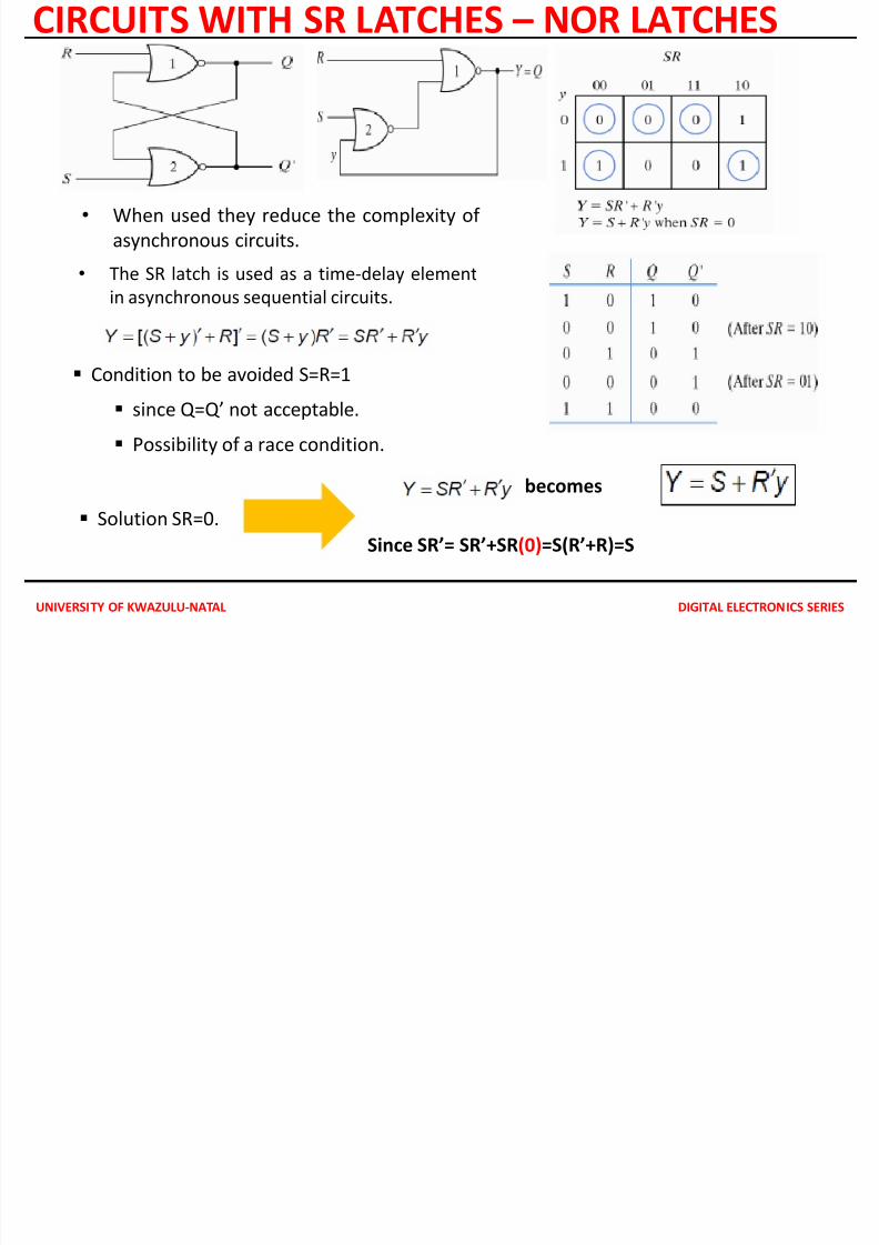
CIRCUITS WITH SR LATCHES NAND LATCHES
7/28/2019 ASYNCRONOUS SEQUENTIAL ANALYSIS
http://slidepdf.com/reader/full/asyncronous-sequential-analysis 18/23
UNIVERSITY OF KWAZULU-NATAL DIGITAL ELECTRONICS SERIES
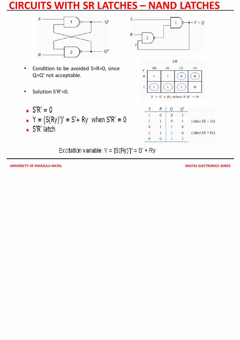
CIRCUITS WITH SR LATCHES – NAND LATCHES
• Condition to be avoided S=R=0, since
Q=Q’ not acceptable.
• Solution S’R’=0.
ANALYSIS WITH LATCHES EXAMPLE
7/28/2019 ASYNCRONOUS SEQUENTIAL ANALYSIS
http://slidepdf.com/reader/full/asyncronous-sequential-analysis 19/23
UNIVERSITY OF KWAZULU-NATAL DIGITAL ELECTRONICS SERIES
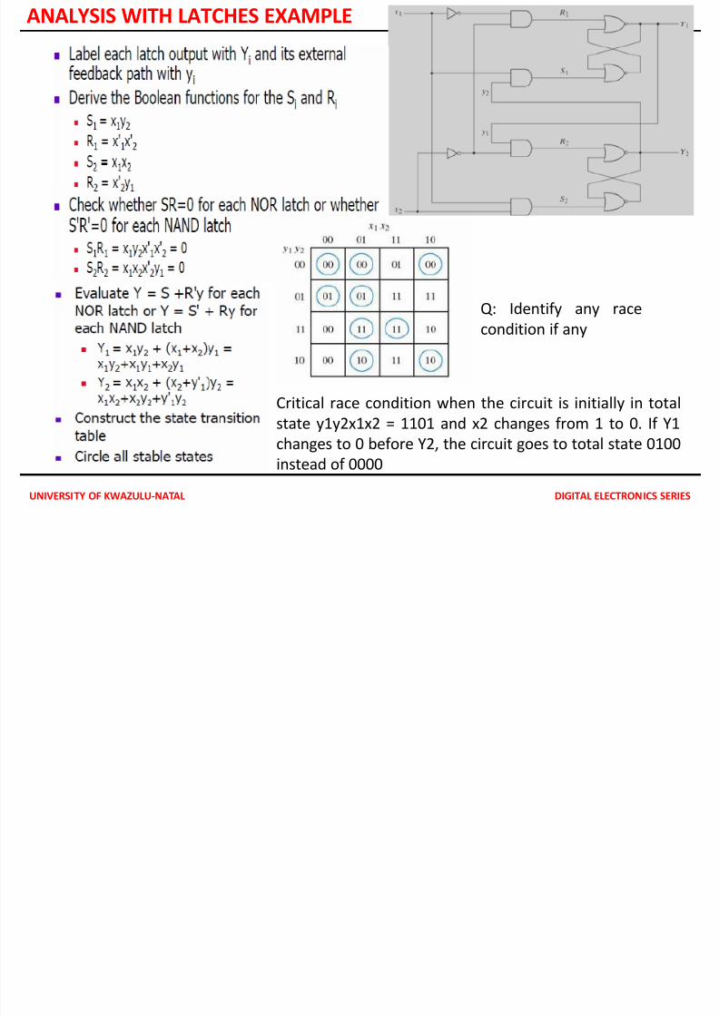
ANALYSIS WITH LATCHES EXAMPLE
Critical race condition when the circuit is initially in total
state y1y2x1x2 = 1101 and x2 changes from 1 to 0. If Y1
changes to 0 before Y2, the circuit goes to total state 0100
instead of 0000
Q: Identify any race
condition if any
ANALYZING AN ASYNCHRONOUS SEQUENTIAL CIRCUIT WITH A LATCH
7/28/2019 ASYNCRONOUS SEQUENTIAL ANALYSIS
http://slidepdf.com/reader/full/asyncronous-sequential-analysis 20/23
UNIVERSITY OF KWAZULU-NATAL DIGITAL ELECTRONICS SERIES
ANALYZING AN ASYNCHRONOUS SEQUENTIAL CIRCUIT WITH A LATCH
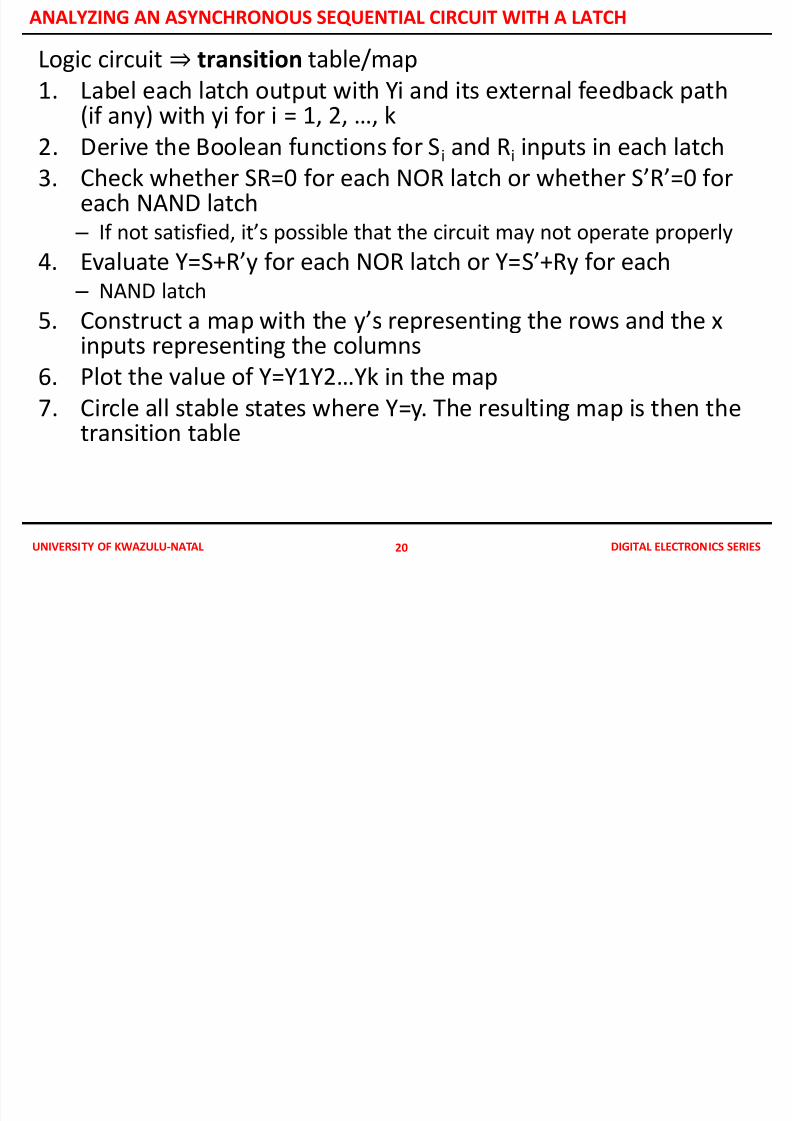
Logic circuit⇒ transition table/map
1. Label each latch output with Yi and its external feedback path(if any) with yi for i = 1, 2, …, k
2. Derive the Boolean functions for Si and Ri inputs in each latch
3. Check whether SR=0 for each NOR latch or whether S’R’=0 foreach NAND latch – If not satisfied, it’s possible that the circuit may not operate properly
4. Evaluate Y=S+R’y for each NOR latch or Y=S’+Ry for each – NAND latch
5. Construct a map with the y’s representing the rows and the xinputs representing the columns
6. Plot the value of Y=Y1Y2…Yk in the map
7. Circle all stable states where Y=y. The resulting map is then thetransition table
20
LATCH EXCITATION TABLE
7/28/2019 ASYNCRONOUS SEQUENTIAL ANALYSIS
http://slidepdf.com/reader/full/asyncronous-sequential-analysis 21/23
UNIVERSITY OF KWAZULU-NATAL DIGITAL ELECTRONICS SERIES
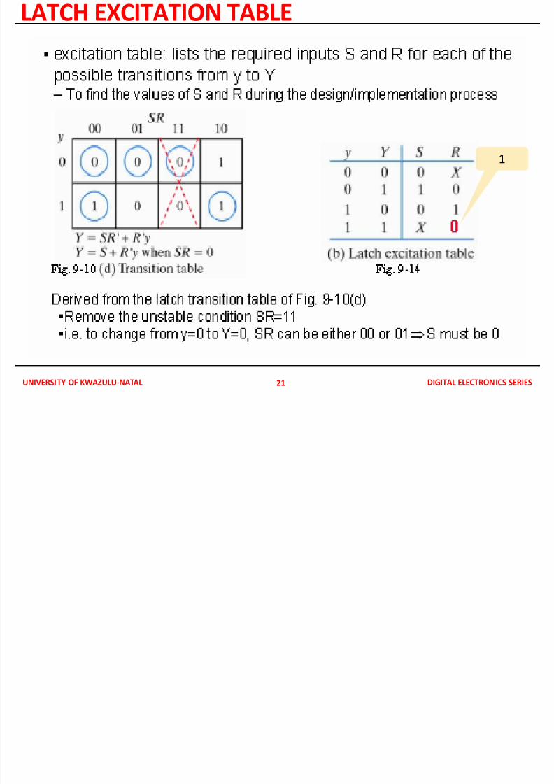
LATCH EXCITATION TABLE
21
1
IMPLEMENTATION WITH AN SR LATCH
7/28/2019 ASYNCRONOUS SEQUENTIAL ANALYSIS
http://slidepdf.com/reader/full/asyncronous-sequential-analysis 22/23
UNIVERSITY OF KWAZULU-NATAL DIGITAL ELECTRONICS SERIES
IMPLEMENTATION WITH AN SR LATCH
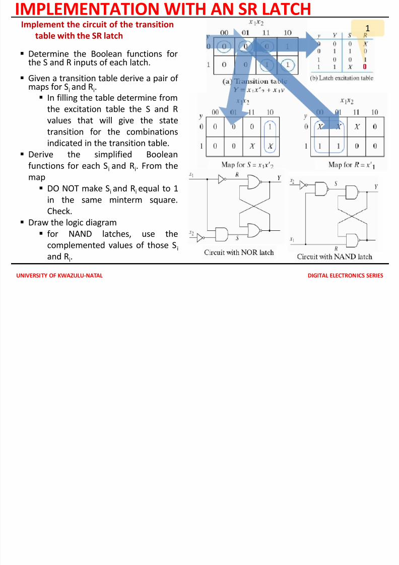
Determine the Boolean functions forthe S and R inputs of each latch.
Given a transition table derive a pair of maps for Si and Ri.
In filling the table determine from
the excitation table the S and R
values that will give the state
transition for the combinationsindicated in the transition table.
Derive the simplified Boolean
functions for each Si and Ri. From the
map
DO NOT make Si and Ri equal to 1
in the same minterm square.Check.
Draw the logic diagram
for NAND latches, use the
complemented values of those Si
and Ri.
Implement the circuit of the transition
table with the SR latch1
IMPLEMENTING WITH SR LATCH
7/28/2019 ASYNCRONOUS SEQUENTIAL ANALYSIS
http://slidepdf.com/reader/full/asyncronous-sequential-analysis 23/23
UNIVERSITY OF KWAZULU NATAL DIGITAL ELECTRONICS SERIES
IMPLEMENTING WITH SR LATCH
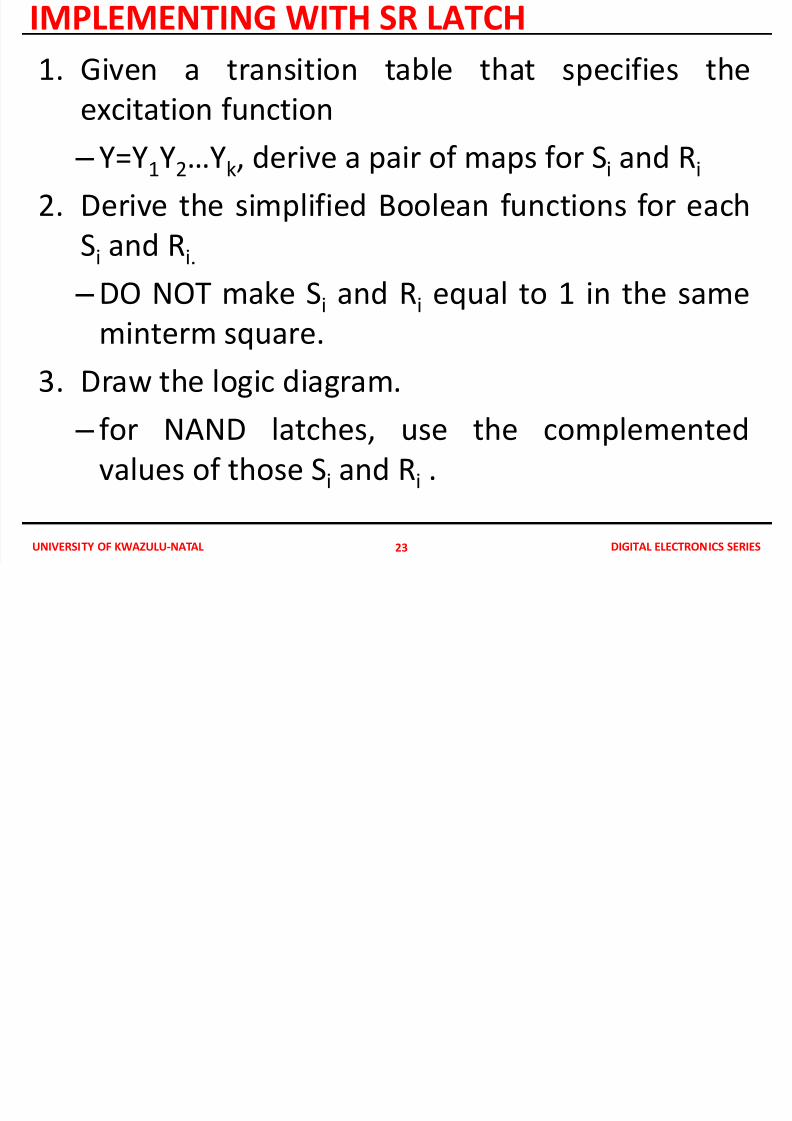
1. Given a transition table that specifies the
excitation function
– Y=Y1Y2…Yk, derive a pair of maps for Si and Ri
2. Derive the simplified Boolean functions for each
Si
and Ri.
– DO NOT make Si and Ri equal to 1 in the same
minterm square.
3. Draw the logic diagram.
– for NAND latches, use the complemented
values of those Si and Ri .
23