atca mss system documentation
DESCRIPTION
MSS System DocumentationTRANSCRIPT
MSS System Documentation, Rel. MSS SR4.0, v.2
Release Overview, MSS System Release 4.0
DN0741515
Issue 1-0
2 DN0741515Issue 1-0
Release Overview, MSS System Release 4.0
Id:0900d80580841adf
The information in this document is subject to change without notice and describes only the product defined in the introduction of this documentation. This documentation is intended for the use of Nokia Siemens Networks customers only for the purposes of the agreement under which the document is submitted, and no part of it may be used, reproduced, modified or transmitted in any form or means without the prior written permission of Nokia Siemens Networks. The documentation has been prepared to be used by professional and properly trained personnel, and the customer assumes full responsibility when using it. Nokia Siemens Networks welcomes customer comments as part of the process of continuous development and improvement of the documentation.
The information or statements given in this documentation concerning the suitability, capacity, or performance of the mentioned hardware or software products are given "as is" and all liability arising in connection with such hardware or software products shall be defined conclusively and finally in a separate agreement between Nokia Siemens Networks and the customer. However, Nokia Siemens Networks has made all reasonable efforts to ensure that the instructions contained in the document are adequate and free of material errors and omissions. Nokia Siemens Networks will, if deemed necessary by Nokia Siemens Networks, explain issues which may not be covered by the document.
Nokia Siemens Networks will correct errors in this documentation as soon as possible. IN NO EVENT WILL Nokia Siemens Networks BE LIABLE FOR ERRORS IN THIS DOCUMENTA-TION OR FOR ANY DAMAGES, INCLUDING BUT NOT LIMITED TO SPECIAL, DIRECT, INDI-RECT, INCIDENTAL OR CONSEQUENTIAL OR ANY LOSSES, SUCH AS BUT NOT LIMITED TO LOSS OF PROFIT, REVENUE, BUSINESS INTERRUPTION, BUSINESS OPPORTUNITY OR DATA,THAT MAY ARISE FROM THE USE OF THIS DOCUMENT OR THE INFORMATION IN IT.
This documentation and the product it describes are considered protected by copyrights and other intellectual property rights according to the applicable laws.
The wave logo is a trademark of Nokia Siemens Networks Oy. Nokia is a registered trademark of Nokia Corporation. Siemens is a registered trademark of Siemens AG.
Other product names mentioned in this document may be trademarks of their respective owners, and they are mentioned for identification purposes only.
Copyright © Nokia Siemens Networks 2011/5/12. All rights reserved
f Important Notice on Product SafetyThis product may present safety risks due to laser, electricity, heat, and other sources of danger.
Only trained and qualified personnel may install, operate, maintain or otherwise handle this product and only after having carefully read the safety information applicable to this product.
The safety information is provided in the Safety Information section in the “Legal, Safety and Environmental Information” part of this document or documentation set.
The same text in German:
f Wichtiger Hinweis zur Produktsicherheit Von diesem Produkt können Gefahren durch Laser, Elektrizität, Hitzeentwicklung oder andere Gefahrenquellen ausgehen.
Installation, Betrieb, Wartung und sonstige Handhabung des Produktes darf nur durch geschultes und qualifiziertes Personal unter Beachtung der anwendbaren Sicherheits-anforderungen erfolgen.
Die Sicherheitsanforderungen finden Sie unter „Sicherheitshinweise“ im Teil „Legal, Safety and Environmental Information“ dieses Dokuments oder dieses Dokumentations-satzes.
DN0741515Issue 1-0
3
Release Overview, MSS System Release 4.0
Id:0900d80580841adf
Table of ContentsThis document has 66 pages.
1 MSS System . . . . . . . . . . . . . . . . . . . . . . . . . . . . . . . . . . . . . . . . . . . . . . 71.1 MSS System Release 4.0 . . . . . . . . . . . . . . . . . . . . . . . . . . . . . . . . . . . . 71.2 Scope of this document . . . . . . . . . . . . . . . . . . . . . . . . . . . . . . . . . . . . . . 9
2 Hardware . . . . . . . . . . . . . . . . . . . . . . . . . . . . . . . . . . . . . . . . . . . . . . . . 112.1 Open MSS . . . . . . . . . . . . . . . . . . . . . . . . . . . . . . . . . . . . . . . . . . . . . . . 11
3 Release upgrade . . . . . . . . . . . . . . . . . . . . . . . . . . . . . . . . . . . . . . . . . . 153.1 Hardware upgrade . . . . . . . . . . . . . . . . . . . . . . . . . . . . . . . . . . . . . . . . . 153.2 Software upgrade . . . . . . . . . . . . . . . . . . . . . . . . . . . . . . . . . . . . . . . . . 153.3 Capacity and performance. . . . . . . . . . . . . . . . . . . . . . . . . . . . . . . . . . . 16
4 End user functionality . . . . . . . . . . . . . . . . . . . . . . . . . . . . . . . . . . . . . . 184.1 IP PBX support in MSS System. . . . . . . . . . . . . . . . . . . . . . . . . . . . . . . 184.2 Enhanced VAD for 3GPP codecs . . . . . . . . . . . . . . . . . . . . . . . . . . . . . 21
5 Connectivity . . . . . . . . . . . . . . . . . . . . . . . . . . . . . . . . . . . . . . . . . . . . . . 235.1 Rate control and SLA support . . . . . . . . . . . . . . . . . . . . . . . . . . . . . . . . 235.2 H.248 load balancer with DX 200-based MSS. . . . . . . . . . . . . . . . . . . . 25
6 Efficiency . . . . . . . . . . . . . . . . . . . . . . . . . . . . . . . . . . . . . . . . . . . . . . . . 286.1 CS voice over I-HSPA . . . . . . . . . . . . . . . . . . . . . . . . . . . . . . . . . . . . . . 286.2 I-HSPA capacity extension in MSS System. . . . . . . . . . . . . . . . . . . . . . 326.3 Support for 3GPP SIP-I TFO -TrFO - supplementary services . . . . . . . 336.4 NPS as CNAP external database . . . . . . . . . . . . . . . . . . . . . . . . . . . . . 356.5 G.711 10 ms packetization support in MSS System . . . . . . . . . . . . . . . 376.6 CS Fallback Phase 1 in MSS System . . . . . . . . . . . . . . . . . . . . . . . . . . 386.7 VLR backup solution in MSS System . . . . . . . . . . . . . . . . . . . . . . . . . . 426.8 CNPS-based Dynamic TDM Circuit Balancer . . . . . . . . . . . . . . . . . . . . 476.9 CNPS-based VLR load balancing for MSS pooling . . . . . . . . . . . . . . . . 50
7 VoIP functionality . . . . . . . . . . . . . . . . . . . . . . . . . . . . . . . . . . . . . . . . . . 537.1 NVS-based LTE voice for early LTE deployments with Fasttrack . . . . . 537.2 SMS MIME support in MSS-based FMC . . . . . . . . . . . . . . . . . . . . . . . . 557.3 Colibria Presence Server for NVS . . . . . . . . . . . . . . . . . . . . . . . . . . . . . 577.4 CK SIM authentication with 2G SIM card. . . . . . . . . . . . . . . . . . . . . . . . 59
Appendix . . . . . . . . . . . . . . . . . . . . . . . . . . . . . . . . . . . . . . . . . . . . . . . . 61
Glossary. . . . . . . . . . . . . . . . . . . . . . . . . . . . . . . . . . . . . . . . . . . . . . . . . 62Terms and abbreviations . . . . . . . . . . . . . . . . . . . . . . . . . . . . . . . . . . . . 62

4 DN0741515Issue 1-0
Release Overview, MSS System Release 4.0
Id:0900d80580841adf
List of FiguresFigure 1 Products directly interfacing the MSS System . . . . . . . . . . . . . . . . . . . . . 8Figure 2 MSS System in Fixed-Mobile Convergence system solutions . . . . . . . . . 9Figure 3 ATCA cabinet . . . . . . . . . . . . . . . . . . . . . . . . . . . . . . . . . . . . . . . . . . . . . 12Figure 4 MSS System architecture with IP PBXs . . . . . . . . . . . . . . . . . . . . . . . . . 19Figure 5 eVAD in MSS System . . . . . . . . . . . . . . . . . . . . . . . . . . . . . . . . . . . . . . . 21Figure 6 H.248 signaling load share . . . . . . . . . . . . . . . . . . . . . . . . . . . . . . . . . . . 26Figure 7 I-HSPA architecture with MSS System and packet core network. . . . . . 29Figure 8 Paging optimization for I-HSPA network in MT transaction . . . . . . . . . . 30Figure 9 Example of simultaneous LTE data and SMS delivery . . . . . . . . . . . . . . 39Figure 10 CS Fallback architecture. . . . . . . . . . . . . . . . . . . . . . . . . . . . . . . . . . . . . 40Figure 11 VLR backup functionality . . . . . . . . . . . . . . . . . . . . . . . . . . . . . . . . . . . . 44Figure 12 CNPS-based Dynamic TDM Circuit Balancer. . . . . . . . . . . . . . . . . . . . . 48Figure 13 CNPS and VLR load balancer . . . . . . . . . . . . . . . . . . . . . . . . . . . . . . . . 51Figure 14 Early LTE access to NVS with SBC-A . . . . . . . . . . . . . . . . . . . . . . . . . . 53Figure 15 SMS over SIP in MSS System . . . . . . . . . . . . . . . . . . . . . . . . . . . . . . . . 55Figure 16 Colibria Presence Server in MSS System . . . . . . . . . . . . . . . . . . . . . . . 58Figure 17 CK SIM authentication in MSS System . . . . . . . . . . . . . . . . . . . . . . . . . 59

DN0741515Issue 1-0
5
Release Overview, MSS System Release 4.0
Id:0900d80580841adf
List of TablesTable 1 Feature table for IP PBX support in MSS System . . . . . . . . . . . . . . . . 20Table 2 Feature table for Enhanced VAD for 3GPP codecs . . . . . . . . . . . . . . . 22Table 3 Feature table for Rate control and SLA support . . . . . . . . . . . . . . . . . . 24Table 4 Feature table for H.248 load balancer with DX 200-based MSS . . . . . 27Table 5 Feature table for CS voice over I-HSPA . . . . . . . . . . . . . . . . . . . . . . . . 31Table 6 Feature table for I-HSPA capacity extension in MSS System . . . . . . . 32Table 7 Feature table for 3GPP SIP-I TFO -TrFO - supplementary services . . 34Table 8 Feature table for NPS as CNAP external database . . . . . . . . . . . . . . . 36Table 9 Feature table for G.711 10 ms packetization support in MSS System . 37Table 10 Feature table for CS Fallback Phase 1 in the MSS system . . . . . . . . . 41Table 11 Benefits by interaction of VLR backup solution with other MSS resilience
solutions . . . . . . . . . . . . . . . . . . . . . . . . . . . . . . . . . . . . . . . . . . . . . . . . 43Table 12 Feature table for VLR backup solution in the MSS System . . . . . . . . . 46Table 13 Feature table for CNPS-based Dynamic TDM circuit Balancer . . . . . . 49Table 14 Feature table for CNPS-based VLR load balancing for MSS pooling . . 51Table 15 Feature table for NVS-based LTE voice for early LTE deployments . . 54Table 16 Feature table for SMS MIME support in MSS-based FMC . . . . . . . . . 56Table 17 Feature table for Colibria Presence Server for NVS . . . . . . . . . . . . . . . 58Table 18 Feature table for CK SIM authentication with 2G SIM card . . . . . . . . . 60Table 19 Explanation for the feature table . . . . . . . . . . . . . . . . . . . . . . . . . . . . . . 61
6 DN0741515Issue 1-0
Release Overview, MSS System Release 4.0
Id:0900d80580841adf

DN0741515Issue 1-0
7
Release Overview, MSS System Release 4.0 MSS System
Id:0900d80580858bf0
1 MSS SystemThe MSC Server System (MSS System) consists of two main products, the MSC Server (MSS) and the Multimedia Gateway (MGW), and a number of supporting network ele-ments, depending on the features and network configuration in use.
The MSS System is a part of a mobile/hybrid operator’s core network providing voice, multimedia and messaging as well as other relevant services for the operator’s subscrib-ers.
The MSS System provides mobile telephony services for both home and business users. Services can be offered either by using the internal service logic (switch-based services) or external service enablers, such as the Intelligent Network (IN).
In addition to circuit-switched mobile network functions, the MSS System also provides voice over IP (VoIP) services for SIP-capable subscribers registering from alternative access types, such as xDSL, cable, or cellular broadband.
1.1 MSS System Release 4.0MSS System Release 4.0 (MSS SR4.0) brings a new combination of product releases and new roadmap features according to Nokia Siemens Networks innovation, standards and feedback from customers. New standards are incorporated into the development of new features as well as into the evolution of already existing features as they become available.
MSS SR4.0 is based on the MSS M14.6 and M16.0, and MGW U5.0 product releases. MSS SR4.0 provides the first step towards an Open MSS System by introducing the ATCA-based Open MSS with M16.0.
NetAct support for MSS SR4.0 is available with OSS5.2 CD2. OSS5.2 CD2 supports M14.6 and U5.0. Support of M16.0 is added in OSS5.3.
In MSS SR4.0, NEMU is only available for M14.6-level MSS. U5.0 does not rely on NEMU; it uses NE3S interfaces with OSS5.2 CD2 instead. M16.0-level MSS does not support NEMU either.
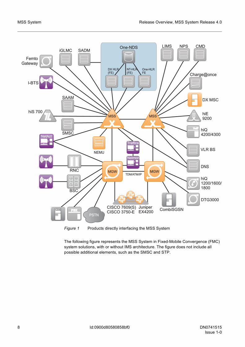
The figure below depicts the main products in the MSS System, with their direct inter-faces to other network elements:
8 DN0741515Issue 1-0
Release Overview, MSS System Release 4.0
Id:0900d80580858bf0
MSS System
Figure 1 Products directly interfacing the MSS System
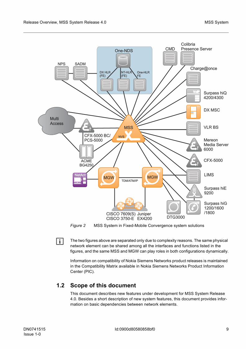
The following figure represents the MSS System in Fixed-Mobile Convergence (FMC) system solutions, with or without IMS architecture. The figure does not include all possible additional elements, such as the SMSC and STP.
BSC
RNC
DX MSCDX MSC
DTG3000DTG3000
CISCO 7609(S)CISCO 7609(S)CISCO 3750-ECISCO 3750-E
Juniper4200EX
Charge@once
CombiSGSN
DNS
SADM
SAAM
iGLMC
FemtoGateway
I-BTS
NT-HLR(FE)
DX HLRDX HLR(FE)
One-HLRFE
One-NDS
DXA
LIMS CMD
hiS 700hiS 700
SMSC
Nelmon
TDM/ATM/IP
EIR
hiQ4200/43004200/4300
hiQ1200/1600/1200/1600/1800
hiE9200
NPS
NEMU
Traffica
MGW
CDS
PSTN
MGW
NetAct
VLR BSVLR BS
MSS MSS
DN0741515Issue 1-0
9
Release Overview, MSS System Release 4.0 MSS System
Id:0900d80580858bf0
Figure 2 MSS System in Fixed-Mobile Convergence system solutions
g The two figures above are separated only due to complexity reasons. The same physical network element can be shared among all the interfaces and functions listed in the figures, and the same MSS and MGW can play roles in both configurations dynamically.
Information on compatibility of Nokia Siemens Networks product releases is maintained in the Compatibility Matrix available in Nokia Siemens Networks Product Information Center (PIC).
1.2 Scope of this documentThis document describes new features under development for MSS System Release 4.0. Besides a short description of new system features, this document provides infor-mation on basic dependencies between network elements.
ACMEBG4250
Surpass hiGSurpass hiG1200/1600/1800
DX MSCDX MSC
DTG3000CISCO 7609(S)CISCO 7609(S)CISCO 3750-ECISCO 3750-E
CFX-5000 BC/CFX-5000 BC/PCS-5000
CFX-5000
SADM
Surpass hiQSurpass hiQ4200/4300
CMD
Surpass hiESurpass hiE9200
TDM/ATM/IP
NPS
MereonMedia ServerMedia Server6000
LIMS
Charge@onceCharge@once
Juniper4200EX
MultiAccess
MGW
NEMU
MGW
ColibriaPresence ServerPresence Server
NT-HLR(FE)
DX HLRDX HLR(FE)
One-HLRFE
One-NDS
DXA
NetActMGW
NEMU
MGW
VLR BSVLR BSMSS
NVS
10 DN0741515Issue 1-0
Release Overview, MSS System Release 4.0
Id:0900d80580858bf0
MSS System
This document also covers MSS System features that may not all require implementa-tion in the MSS and MGW, but enable new use cases and new possibilities in the way the network elements can be used. The focus of this documents lies on significant new or changed system level use cases and capabilities.
This document is not a comprehensive description of all new features and functionalities within the MSS System. This means, for example, that features and hardware develop-ment within one network element only (for example, statistics provided by the MSS) are described in product-specific documents.
This document does not cover features either which have been postponed from earlier releases.
For product-specific information, see the M14.6 Release Overview or M16.0 Release Content Description for M-releases (MSS/NVS, DX MSC, DX HLR, CDS), and Multime-dia Gateway U5.0 Release Overview or MGW U5.0 Product Documentation.
This document does not necessarily provide information on whether a feature is optional or generic. This information may be given in the product-specific Release Overview doc-uments.
Effects on other network elements and network domains are handled in respective doc-umentation.
This document is NON BINDING. The content of this document is subject to change mainly due to customer feedback, the status of standardization, and the progress of the system program and related product programs.

DN0741515Issue 1-0
11
Release Overview, MSS System Release 4.0 Hardware
Id:0900d80580881569
2 HardwareMSS System Release 4.0 offers two options for deploying MSC Server:
• MSS based on field-proven DX 200 HW and SW platforms • Open MSS based on cutting-edge Advanced Telecommunication Computing Archi-
tecture (ATCA) HW and ADX2 SW platforms
For Multimedia Gateway, MSS System Release 4.0 relies on IPA2800 platform-based MGW in U5.0 release. ATCA-based Open Multimedia Gateway will be introduced in Ui5.0 release, as part of MSS SR4.2.
2.1 Open MSSNokia Siemens Networks offers the Open MSS based on Commercial Off The Shelf (COTS) ATCA hardware for the MSC Server (MSS) product from M16.0.
The ATCA hardware is a telecommunication standard hardware platform which can be deployed in all mobile networks regardless of the functionality built upon it.
12 DN0741515Issue 1-0
Release Overview, MSS System Release 4.0
Id:0900d80580881569
Hardware
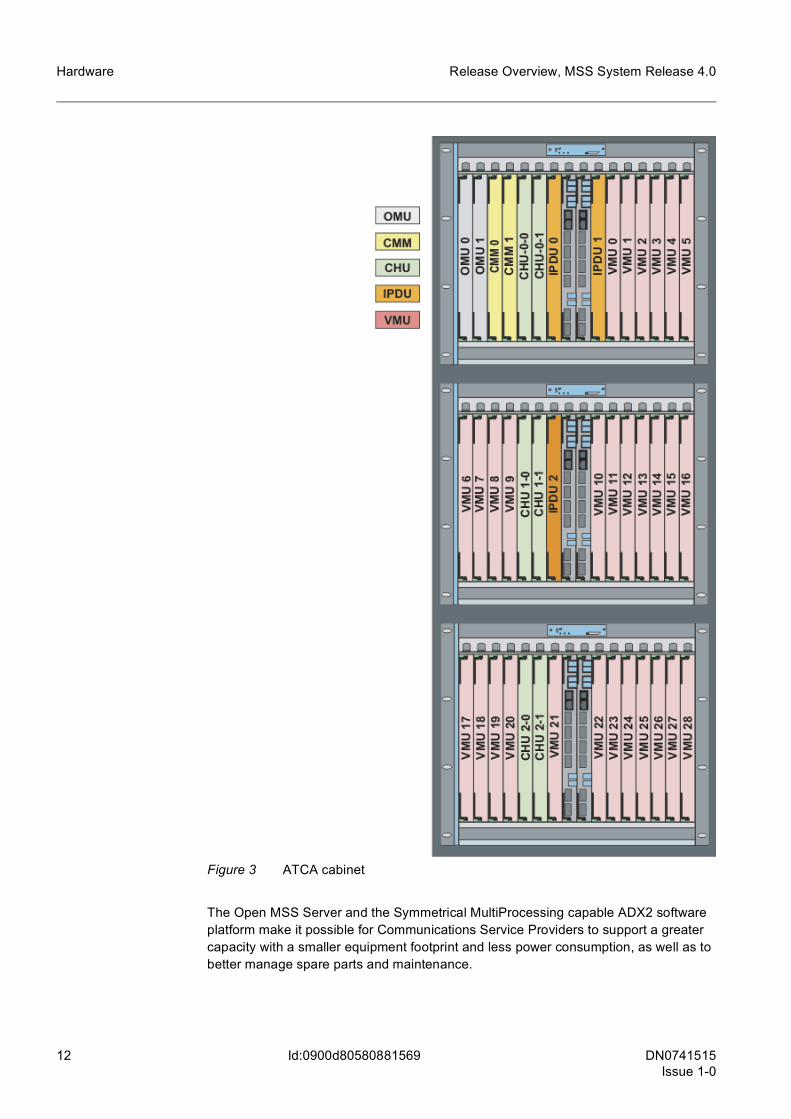
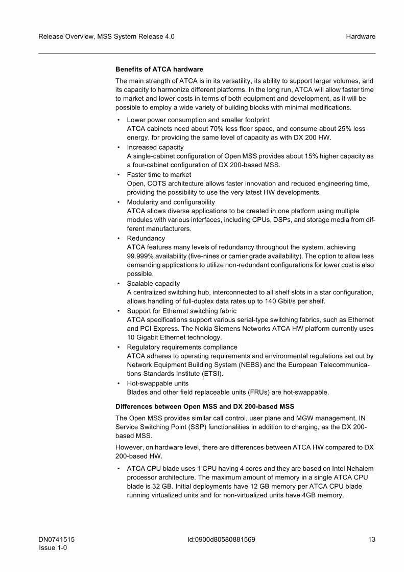
Figure 3 ATCA cabinet
The Open MSS Server and the Symmetrical MultiProcessing capable ADX2 software platform make it possible for Communications Service Providers to support a greater capacity with a smaller equipment footprint and less power consumption, as well as to better manage spare parts and maintenance.
DN0741515Issue 1-0
13
Release Overview, MSS System Release 4.0 Hardware
Id:0900d80580881569
Benefits of ATCA hardwareThe main strength of ATCA is in its versatility, its ability to support larger volumes, and its capacity to harmonize different platforms. In the long run, ATCA will allow faster time to market and lower costs in terms of both equipment and development, as it will be possible to employ a wide variety of building blocks with minimal modifications.
• Lower power consumption and smaller footprintATCA cabinets need about 70% less floor space, and consume about 25% less energy, for providing the same level of capacity as with DX 200 HW.
• Increased capacityA single-cabinet configuration of Open MSS provides about 15% higher capacity as a four-cabinet configuration of DX 200-based MSS.
• Faster time to marketOpen, COTS architecture allows faster innovation and reduced engineering time, providing the possibility to use the very latest HW developments.
• Modularity and configurabilityATCA allows diverse applications to be created in one platform using multiple modules with various interfaces, including CPUs, DSPs, and storage media from dif-ferent manufacturers.
• RedundancyATCA features many levels of redundancy throughout the system, achieving 99.999% availability (five-nines or carrier grade availability). The option to allow less demanding applications to utilize non-redundant configurations for lower cost is also possible.
• Scalable capacityA centralized switching hub, interconnected to all shelf slots in a star configuration, allows handling of full-duplex data rates up to 140 Gbit/s per shelf.
• Support for Ethernet switching fabricATCA specifications support various serial-type switching fabrics, such as Ethernet and PCI Express. The Nokia Siemens Networks ATCA HW platform currently uses 10 Gigabit Ethernet technology.
• Regulatory requirements complianceATCA adheres to operating requirements and environmental regulations set out by Network Equipment Building System (NEBS) and the European Telecommunica-tions Standards Institute (ETSI).
• Hot-swappable unitsBlades and other field replaceable units (FRUs) are hot-swappable.
Differences between Open MSS and DX 200-based MSSThe Open MSS provides similar call control, user plane and MGW management, IN Service Switching Point (SSP) functionalities in addition to charging, as the DX 200-based MSS.
However, on hardware level, there are differences between ATCA HW compared to DX 200-based HW.
• ATCA CPU blade uses 1 CPU having 4 cores and they are based on Intel Nehalem processor architecture. The maximum amount of memory in a single ATCA CPU blade is 32 GB. Initial deployments have 12 GB memory per ATCA CPU blade running virtualized units and for non-virtualized units have 4GB memory.
14 DN0741515Issue 1-0
Release Overview, MSS System Release 4.0
Id:0900d80580881569
Hardware
• SS7 TDM-based signaling connectivity is not available on ATCA HW. SS7 over IP (SIGTRAN) connectivity can be used instead, or IPA2800-based MGW can be used as signalling gateway (SGW).
• External optical drives are not available. Software delivery and data transfer between the network element and the "external world" is carried out by using either USB HDD, USB memory stick, or IP connectivity.
• SIGU, BSU, and SCPU signaling units are merged into the single GISU unit type. • WSCU (for Web Service Interface) is not part of M16.0. • H.248, SIP, and M3UA load balancing features are supported by DX 200-based
MSS and recommended to be used. M3UA load balancing is available for Open MSS as well. Support for SIP and H.248 load balancing features in Open MSS will be available in later MSS System releases.
• Multiple logical functional units, for example, CMU, STU, VLRU, and GISU, are served by a single ATCA CPU blade via using virtualization framework, that is, vir-tualization manager units (VMUs).
• IP connectivity is provided by using ATCA-based AHUB3-A LAN switch units located in each shelf. Alternatively, direct IP connectivity can be provided for some CPU blades, for example, N+1 IPDU units, to the site switches using the ports on CPU rear transition modules.
• In M16.0, only single cabinet configuration is available for Open MSS. Support for two-cabinet configurations is planned for Ma16.1.
Additionally, TDM-based O&M interfaces (X.25) are not supported, only IP-based inter-faces exist.
For further information on Open MSS refer to the Open MSS Product Description in M-release Product Documentation.
DN0741515Issue 1-0
15
Release Overview, MSS System Release 4.0 Release upgrade
Id:0900d80580881f25
3 Release upgrade
3.1 Hardware upgradeMSC Server M14.6There are no mandatory hardware changes to M14.6 MSC Server, therefore, no upgrade is needed.
If operators want to use the enhanced M14.6 MSS capacities, ESB24-D SWU upgrade is needed to EMB (applicable only for M14 First Delivery HW).
MSC Server M16.0As M16.0 is available only for Open MSS-based on newly installed ATCA hardware, hardware upgrade from DX 200-based MSS is not supported. ATCA HW is productized as part of AB3 product program.
Multimedia Gateway U5.0For MGWs on U4 or U3C hardware level, the following hardware requirement is man-datory for upgrading the MGWs to U5.0:
• O&M interface upgrade with removing integrated NEMU units (MCPC2-A cards)NE3S based management interfaces are terminated directly to the OMU units.
If the MGW is initially on U1.5, U2 or U3A/B, some CPU upgrades might also be needed (for example, OMU CPU upgrade to CCP18-A).
U5.0 offers optional hardware upgrade possibilities as listed below:
• TDM/STM-1 interface units, IW1S1 and IW1S1-A, can be upgraded with IW8S1-A. This provides the operator with– STM/1OC3– MSP1+1 with equipment protection (2N)
• LAN switch unit upgrade: the ESA24 can be upgraded with ESA40-A. The upgrade enables– physical separation of O&M and signaling traffic– an L3 layer-capable unitL3 connectivity for user plane (UP) requires a dedicated ESA40-A SWU unit pairs, and maximum 2 NP2GE-A 2N redundant pairs can be connected to the ESA40-A pair for L3 connectivity for UP. However, the maximum number of 2N redundant NP2GE-A pairs in a single MGW is still 6 as was already in the previous U4.2 MGW release.
• IP user plane upgrade with SF10E and NPGEP (introduced in U4.2) is possible also in U5.0.
3.2 Software upgradeMSC Server M14.6All existing MSS elements can be upgraded to M14.6.
Middleware software for DX 200-based MSC Server is provided by B12 platform release.
16 DN0741515Issue 1-0
Release Overview, MSS System Release 4.0
Id:0900d80580881f25
Release upgrade
MSC Server M16.0M16.0 application SW is based on M14.6 application SW as is adapted to ADX2 platform software and the underlying ATCA HW.
Multimedia Gateway U5.0All existing MGW elements (upgraded to latest U4.2 software level) can be upgraded to U5.0 software after the mandatory hardware upgrades have been performed. If only software is upgraded to U5.0, the capacity of the MGW does not increase, but with hardware extension, more capacity is gained. The software upgrade provides the pos-sibility to introduce new U5.0 functionalities.
g It is recommended to use the latest ESB and ESA eSW versions available in the CD deliveries.
3.3 Capacity and performanceMSC Server M14.6With M14 First Delivery HW and ESB24-D SWU upgrades to EMB, the main capacity figures for M14.6 MSS are as follows:
• 4M subs dynamic VLR capacity • 1M VoIP subscribers (Dynamic capacity distribution of 2G/3G/VoIP subscribers) • 3.5M BHCA (Nokia Siemens Networks profile) • 7M BHCA (basic profile) • 110 000 simultaneous calls • 40M subs VLR pooling capacity (MSS Pooling figures based on VLR capacity)
With M14 First Delivery HW but without ESB24-D SWU upgrades to EMB, and with M12 & M13 First Delivery HW, the main capacity figures for M14.6 MSS are as follows:
• 3M subs dynamic VLR capacity • 1M VoIP subscribers (Dynamic capacity distribution of 2G/3G/VoIP subscribers) • 2.5M BHCA (Nokia Siemens Networks profile) • 5M BHCA (basic profile) • 110 000 simultaneous calls • 30M subs VLR capacity
g The Nokia Siemens Networks traffic profile calculates traffic volume for each subscriber with one BHCA and one SMS per hour. In the basic traffic profile, there is no such cor-relation between the number of subscribers and BHCAs or SMSs. In fact, these are extreme values from both ends, and in customer networks several kinds of traffic profiles can exist.
MSC Server M16.0The main capacity figures for M16.0 Open MSS are as follows:
• 9M subs static capacity • 4M BHCA (Nokia Siemens Networks profile) • 8M BHCA (basic profile) • 120 000 simultaneous calls • Full 2G/3G/VoIP capacity
DN0741515Issue 1-0
17
Release Overview, MSS System Release 4.0 Release upgrade
Id:0900d80580881f25
• 50M subs VLR pooling capacity (MSS Pooling figures based on VLR capacity)
Multimedia Gateway U5.0The main capacity figures for MGW U5.0 new delivery are as follows:
• 4M BHCA • Up to 80 000 simultaneous calls • 1.440 E1/T1 • 56+56 (2N) STM-1/OC-3 for TDM or • 56+56 (2N) STM-1/OC-3 for ATM or • 56 (1N) STM-1/OC-3 for ATM • 12+12 (2N) Gb Ethernet for user plane with L2 connectivity • 4+4 (2N) Gb Ethernet for user plane with L3 connectivity • 2+2 Gb Ethernet for control plane and O&M traffic
18 DN0741515Issue 1-0
Release Overview, MSS System Release 4.0
Id:0900d80580863070
End user functionality
4 End user functionality
4.1 IP PBX support in MSS SystemShort descriptionThe MSS System provides a direct interface to IP Private Branch Exchanges (PBXs), SIP User-Network Interface (UNI), which enables direct IP peering between SIP-enabled Communications Service Provider (CSP) networks and SIP-enabled enterprise networks by using the basic call-related capabilities of the MSS System.
MSS SR4.0 introduces a first phase of functionalities for IP PBX support in MSS System. Further functionalities are planned to be implemented in MSS SR4.1.
Operator benefitWith IP PBX support in MSS System, operators can
• fulfill regulatory requirements to screen received calling identities from untrusted domains of IP PBXs; or when receiving presentation restricted indication from a caller, the calling identity is not sent to untrusted domains of IP PBXs,
• connect various IP PBXs to the core network and provide PBX-like connectivity at call control layer, similar to ISDN-based DSS1 connections.
Implementation in earlier releasesThe Nokia Siemens Networks MSS System supports interoperability of telecom services between Internet Protocol Multimedia networks (IM CN) and the circuit switched net-works. Furthermore, the MSS System supports traditional ISDN-based PBX interfaces, such as 30B+D and Digital Private Network Signaling System (DPNSS), providing the interoperability between the enterprise networks and the mobile/PSTN networks. However, it does not support interoperability of the telecom services between IP-based enterprise networks and Circuit Switched networks (PLMN/PSTN).
MSS SR4.0 implementationThe new SIP UNI in the MSS System enables direct IP peering, that is, VoIP-based tele-phony between SIP-enabled CSP networks and SIP-enabled enterprise networks.
Concerning this SIP UNI interface, the IP PBX devices do not make SIP registration to a SIP-enabled CSP network. The MSS System manages incoming and outgoing SIP calls and provides the call control and signaling functions for the interoperability calls between IP PBXs and the PLMN. The MSS provides similar call control functions for IP PBX which are already provided for the traditional PBX interfaces, such as calling line identification (CLI) screening, number normalization, PBX specific routing and charging, IN SSF, and so on.
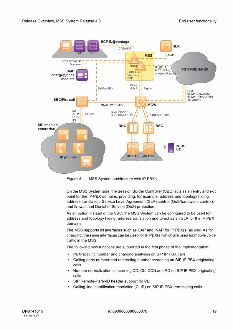
The following figure depicts an MSS System architecture with related products and func-tional network elements. In the figure, the functional elements of the MSS are shown as one combined physical node presenting the most cost-effective solution for the opera-tors. However, if needed, the MSS System also supports combining one or more of these functions into separate physical nodes, for example, MGCF configured as a standalone node (MSS) and GMSCS, VMSC-S and SSF configured into an another single node (MSS).
DN0741515Issue 1-0
19
Release Overview, MSS System Release 4.0 End user functionality
Id:0900d80580863070
Figure 4 MSS System architecture with IP PBXs
On the MSS System side, the Session Border Controller (SBC) acts as an entry and exit point for the IP PBX domains, providing, for example, address and topology hiding, address translation, Service Level Agreement (SLA) control (QoS/bandwidth control), and firewall and Denial of Service (DoS) protection.
As an option instead of the SBC, the MSS System can be configured to be used for address and topology hiding, address translation and to act as an SLA for the IP PBX domains.
The MSS supports IN interfaces such as CAP and INAP for IP PBX(s) as well. As for charging, the same interfaces can be used for IP PBX(s) which are used for mobile voice traffic in the MSS.
The following new functions are supported in the first phase of the implementation:
• PBX-specific number and charging analyses on SIP IP PBX calls • Calling party number and redirecting number screening on SIP IP PBX originating
calls • Number normalization concerning CD, CLI OCN and RD on SIP IP PBX originating
calls • SIP Remote-Party-ID header support for CLI • Calling line identification restriction (CLIR) on SIP IP PBX terminating calls
MSS
MGCF
GMSC-S/VMDC-S/SSF
SCF IN@vantage
CMDcharge@once
mediate
HLR
MGW
RNC BSC
3G BTS 2G BTS
2G/3GUE
SBC/Firewall
IP phones
....
....
SIP enabledenterprise
PSTN/ISDN/PBX
SIP UNI
Mb (RTP/UDP/IP)
Mj/Mg (SIP)
SFTP/FTP/GTPDiameter
CAP/INAP
SCPSNPMAP
Nc (ISUP,BICC, SIP-I,or other #7 sign.)
SigtranMn/McH.248
TDM/Nb UP (AAL2/ATM)Nb UP (RTP/UDP/IP)RTP/UDP/IP
A (BSSAP, TDM)Iu-Cs (RANAP)Iu UP (AAL2/ATM)
Mb (RTP/UDP/IP)
Mb(RTP/UDP/IP)
20 DN0741515Issue 1-0
Release Overview, MSS System Release 4.0
Id:0900d80580863070
End user functionality
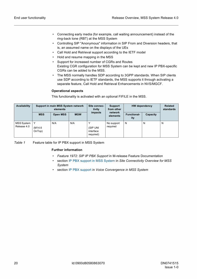
• Connecting early media (for example, call waiting announcement) instead of the ring-back tone (RBT) at the MSS System
• Controlling SIP "Anonymous" information in SIP From and Diversion headers, that is, an assumed name on the displays of the UEs
• Call Hold and Retrieval support according to the IETF model • Hold and resume mapping in the MSS • Support for increased number of CGRs and Routes
Existing CGR configuration for MSS System can be kept and new IP PBX-specific CGRs can be added to the MSS.
• The MSS normally handles SDP according to 3GPP standards. When SIP clients use SDP according to IETF standards, the MSS supports it through activating a separate feature, Call Hold and Retrieval Enhancements in NVS/MGCF.
Operational aspectsThis functionality is activated with an optional FIFILE in the MSS.
Further information
• Feature 1972: SIP IP PBX Support in M-release Feature Documentation • section IP PBX support in MSS System in Site Connectivity Overview for MSS
System • section IP PBX support in Voice Convergence in MSS System
Availability Support in main MSS System network elements
Site connec-tivity
impacts
Support from other
network elements
HW dependency Related standards
MSS Open MSS MGW Functional-ity
Capacity
MSS System Release 4.0
Y
(M14.6 OnTop)
N/A N/A Y
(SIP UNI interface required)
No support required
N N N
Table 1 Feature table for IP PBX support in MSS System
DN0741515Issue 1-0
21
Release Overview, MSS System Release 4.0
Id:0900d8058086306e
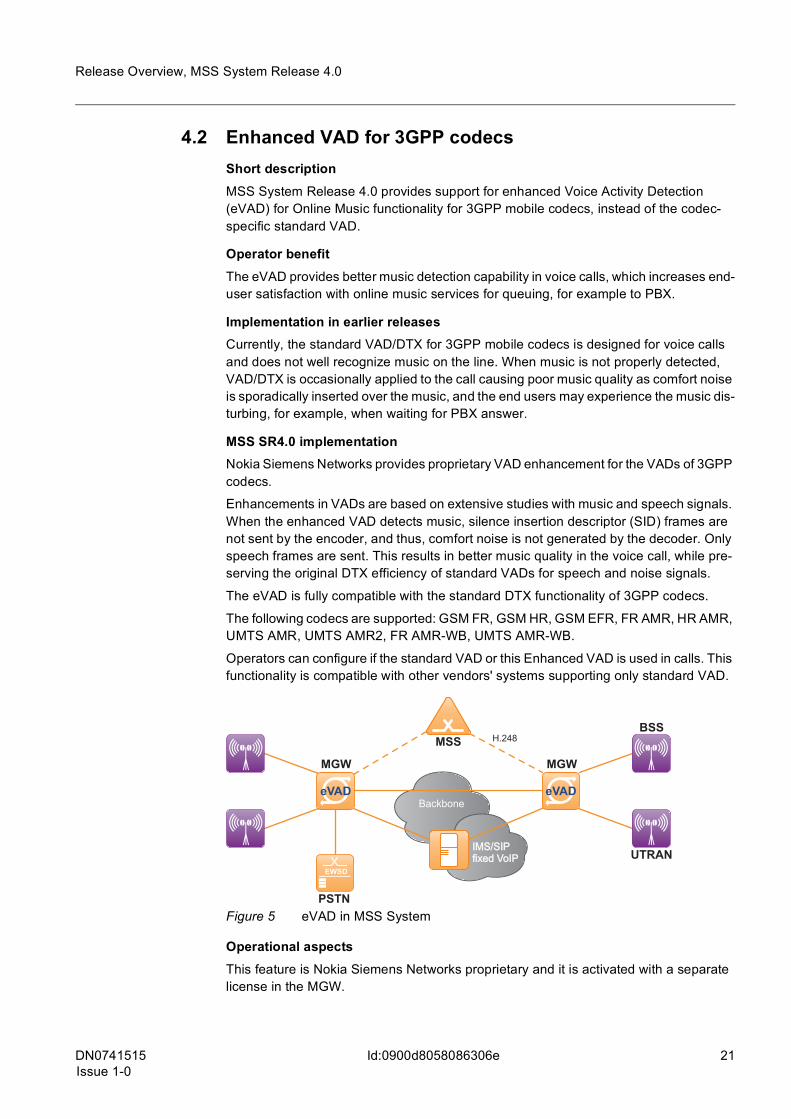
4.2 Enhanced VAD for 3GPP codecsShort descriptionMSS System Release 4.0 provides support for enhanced Voice Activity Detection (eVAD) for Online Music functionality for 3GPP mobile codecs, instead of the codec-specific standard VAD.
Operator benefitThe eVAD provides better music detection capability in voice calls, which increases end-user satisfaction with online music services for queuing, for example to PBX.
Implementation in earlier releasesCurrently, the standard VAD/DTX for 3GPP mobile codecs is designed for voice calls and does not well recognize music on the line. When music is not properly detected, VAD/DTX is occasionally applied to the call causing poor music quality as comfort noise is sporadically inserted over the music, and the end users may experience the music dis-turbing, for example, when waiting for PBX answer.
MSS SR4.0 implementationNokia Siemens Networks provides proprietary VAD enhancement for the VADs of 3GPP codecs.
Enhancements in VADs are based on extensive studies with music and speech signals. When the enhanced VAD detects music, silence insertion descriptor (SID) frames are not sent by the encoder, and thus, comfort noise is not generated by the decoder. Only speech frames are sent. This results in better music quality in the voice call, while pre-serving the original DTX efficiency of standard VADs for speech and noise signals.
The eVAD is fully compatible with the standard DTX functionality of 3GPP codecs.
The following codecs are supported: GSM FR, GSM HR, GSM EFR, FR AMR, HR AMR, UMTS AMR, UMTS AMR2, FR AMR-WB, UMTS AMR-WB.
Operators can configure if the standard VAD or this Enhanced VAD is used in calls. This functionality is compatible with other vendors' systems supporting only standard VAD.
Figure 5 eVAD in MSS System
Operational aspectsThis feature is Nokia Siemens Networks proprietary and it is activated with a separate license in the MGW.
Backbone
MGWMGW
MSS
IMS/SIPfixed VoIPIMS/SIPfixed VoIP
H.248BSS
UTRAN
PSTN
eVAD eVAD

22 DN0741515Issue 1-0
Release Overview, MSS System Release 4.0
Id:0900d8058086306e
Further information
• User Plane Processing in MGW in MGW Product Documentation • section Features affecting end-to-end QoS in Quality of Service in MSS System
Availability Support in main MSS System network elements
Site connec-tivity
impacts
Support from other
network elements
HW dependency Related standards
MSS Open MSS MGW Functional-ity
Capacity
MSS System Release 4.0
N/A N/A Y
(U5.0)
N No support required
N N Proprietary
Table 2 Feature table for Enhanced VAD for 3GPP codecs
DN0741515Issue 1-0
23
Release Overview, MSS System Release 4.0 Connectivity
Id:0900d805808630a5
5 Connectivity
5.1 Rate control and SLA supportShort descriptionThe MSS System supports Service Level Agreement (SLA) monitoring and admission control of SIP messages for each Fully Qualified Domain Name (FQDN) in the MSS.
Operator benefitWith the IP Realm feature in the MSS, available since MSS SR3.3, operators can manage both their IP networks and connections to external networks more effectively. The second phase of the feature:
• Provides SIP session and rate control for Admission Control and SLA enforcement within PLMNs and with IP interconnections between PLMNs and PSTNs;
• Protects the network through SIP session and rate control when the MSS is deployed as an Interconnect Border Control function (I-BCF);
• Provides SLA monitoring per connected network and per network element.
Implementation in earlier releasesMSS SR3.3 introduced multiple listening points (MLPs) for IP realms in the MSS, but it does not support SLA monitoring.
The MGW already provides functionality for the user plane with the Multiple Isolated IP Networks feature.
MSS SR4.0 implementationWith SLA monitoring, operators can measure on each FQDN:
• Peak, average, and cumulative number of sessions • Data on various rates, number of messages, and number of rejected sessions
With this functionality, operators can configure SLA-related rate and parallel session limits for root FQDNs, including:
• Number of parallel sessions (calls) • INVITE request rates • MESSAGE request rates • REGISTER request rates • Other initial requests rates (SUBSCRIBE, PUBLISH and unsolicited NOTIFY
messages in both incoming and outgoing directions
Session and rate control enables basic SIP protection against malfunctioning SIP devices and SIP attacks.
Session and rate control takes place FQDN level. When SIP signaling determines the incoming circuit group (CGR) or call control determines the outgoing route CGR, the embedded I-BCF checks the session and rate control parameters associated to the par-ticular FQDN.
Operational aspectsThis functionality is activated with a separate licence in the MSS.
For SIP/SIP-I, UDP/TCP and SCTP are supported as transport protocols.
24 DN0741515Issue 1-0
Release Overview, MSS System Release 4.0
Id:0900d805808630a5
Connectivity
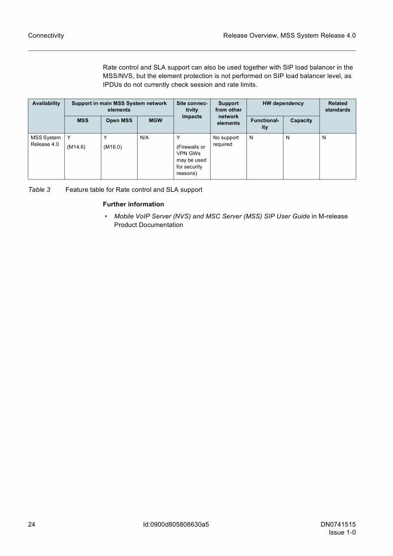
Rate control and SLA support can also be used together with SIP load balancer in the MSS/NVS, but the element protection is not performed on SIP load balancer level, as IPDUs do not currently check session and rate limits.
Further information
• Mobile VoIP Server (NVS) and MSC Server (MSS) SIP User Guide in M-release Product Documentation
Availability Support in main MSS System network elements
Site connec-tivity
impacts
Support from other
network elements
HW dependency Related standards
MSS Open MSS MGW Functional-ity
Capacity
MSS System Release 4.0
Y
(M14.6)
Y
(M16.0)
N/A Y
(Firewalls or VPN GWs may be used for security reasons)
No support required
N N N
Table 3 Feature table for Rate control and SLA support
DN0741515Issue 1-0
25
Release Overview, MSS System Release 4.0
Id:0900d805808630a3
5.2 H.248 load balancer with DX 200-based MSSShort descriptionA significant enhancement to the current MSC Server System IP solution is the introduc-tion of load balancing for the H.248 interface between the MSS and MGW.
H.248 load balancing enables in-built load sharing.
Operator benefitH.248 load balancing provides the operators with the following benefits:
• MSS signaling unit (SIGU) resources can be used as a flexible pool.This means that the operator does not need to configure each SIGU in the MSS with MGW ISUs in order to match the capacities of these units in the most optimal way. This results in easier network planning.
• MGW ISU resources can be used as a flexible pool.This means that the operator does not need to configure each ISU with H.248 link. This results in easier network planning and less manual configuration work.
• Free configuration inside the virtual MGWThis enables virtual MGWs with higher capacity. The MGW can even be configured as one virtual MGW. Larger TDM circuit groups (CGR) enable optimized usage of TDM links.
• Improved IP address management enables OPEX savings and prevents configura-tion errors.
• Improved interoperability • Improved IP security with topology hiding. Only two IP addresses (SCTP multihom-
ing) are visible outside the network element for each H.248 unit pool in MSS and for each MISU unit.
Implementation in earlier releasesIn the current architecture the amount of virtual MGWs is related to the amount of ISUs in the MGW: every ISU requires at least one H.248 link. In addition, the virtual MGWs need to be aligned with context handling capacity of the SIGUs in the MSS. One ISU in the MGW has approximately three times the capacity compared to the SIGU in the MSS. SCTP associations (from each ISU in the MSS) are configured one by one in each ISU of the MGW.
MSS SR4.0 implementationWith H.248 load balancing, the number of IP addresses for the control plane can be reduced. This means that less IP addresses are needed than ISU units. As a result, the number of the virtual MGWs can be significantly reduced - from 17 to 4-6, depending on the SIGTRAN/SS7 configuration.
In the MSS, the number of H.248 interfaces is reduced by introducing SIGU groups. Each SIGU group controls up to 30 virtual MGWs. This is enabled using the IP Director Units (IPDU).The signaling load can be shared equally between ISU units. Load sharing is done by sharing the ISUs’ CPU capacity.
Load sharing introduced the following new concepts for the MGW:
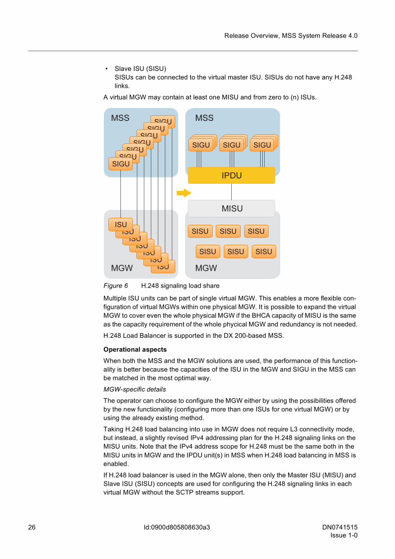
• Master ISU (MISU)A MISU may have one or several H.248 links connected to it. The virtual MGW contains at least one MISU. A MISU can also act as a slave ISU for another MISU.
26 DN0741515Issue 1-0
Release Overview, MSS System Release 4.0
Id:0900d805808630a3
• Slave ISU (SISU)SISUs can be connected to the virtual master ISU. SISUs do not have any H.248 links.
A virtual MGW may contain at least one MISU and from zero to (n) ISUs.
Figure 6 H.248 signaling load share
Multiple ISU units can be part of single virtual MGW. This enables a more flexible con-figuration of virtual MGWs within one physical MGW. It is possible to expand the virtual MGW to cover even the whole physical MGW if the BHCA capacity of MISU is the same as the capacity requirement of the whole phycical MGW and redundancy is not needed.
H.248 Load Balancer is supported in the DX 200-based MSS.
Operational aspectsWhen both the MSS and the MGW solutions are used, the performance of this function-ality is better because the capacities of the ISU in the MGW and SIGU in the MSS can be matched in the most optimal way.
MGW-specific details
The operator can choose to configure the MGW either by using the possibilities offered by the new functionality (configuring more than one ISUs for one virtual MGW) or by using the already existing method.
Taking H.248 load balancing into use in MGW does not require L3 connectivity mode, but instead, a slightly revised IPv4 addressing plan for the H.248 signaling links on the MISU units. Note that the IPv4 address scope for H.248 must be the same both in the MISU units in MGW and the IPDU unit(s) in MSS when H.248 load balancing in MSS is enabled.
If H.248 load balancer is used in the MGW alone, then only the Master ISU (MISU) and Slave ISU (SISU) concepts are used for configuring the H.248 signaling links in each virtual MGW without the SCTP streams support.
SIGUSIGU
SIGUSIGU
SIGUSIGU
SIGU
MSS
MGW ISUISU
ISUISU
ISUISU
ISU
MGW
MISU
SISU SISU SISU
SISU SISU SISU
SIGUSIGUSIGUSIGUSIGUSIGUSIGUSIGUSIGU
MSS
IPDU

DN0741515Issue 1-0
27
Release Overview, MSS System Release 4.0
Id:0900d805808630a3
MSS-specific details
The load balancer functionality requires the IPDU functional unit. The IPDU is based on Linux technology. The hardware configuration of the IPDU is as follows:
• one CPU (CP816-AC/CP816-A) with memory • one Power Supply for Cartridge (PSC6-CB/PSC6-C)
The IPDUs can be taken into use in the MSS either as an upgrade or as part of new deliveries. L3 connectivity is required in the MSS for Control LAN. This has site connec-tivity impacts as the existing L2 connectivity model is migrated to L3 connectivity model by using a new aggregating SWU pair in L3 mode to which the new IPDU units are con-nected. If H.248 load balancer is used in the MSS alone, SCTP streams must be sup-ported for H.248. Note that the IPv4 address scope for H.248 must be the same both in the MISU units in MGW and the IPDU unit(s) in MSS when H.248 load balancing in MSS is enabled.
H.248 load balancer can be used in the MSS only, in the MGW only, or it can also be used in both in the MGW and in the MSS at the same time.
Further information
• Feature 1840: High Capacity Virtual MGW Support in MSC Server in M-release Feature Documentation
• section Planning H.248 load balancer in MSS System Network Planning • section H.248 Load Balancing in MGW and MSS in MSS System Network Resil-
ience • Site Connectivity Guidelines for MSS System and Migration to MSS System docu-
ments
Avail-ability
Support in main MSS System network elements
Other related
products
Site con-nectivity impacts
Support from other
network element
s
HW dependency Related stan-dards
MSS Open MSS
MGW Func-tionality
Capacity
MSS System Release 4.0
Y
(M14.6 top)
N
(will be supported in Ma16.1)
Y
(U4.2)
Y
(U5.0)
Y
(OSS 5.2)
Y
(see opera-tional aspects)
N/A Y
(see opera-tional aspects)
N Y
(3GPP TR 43.9033GPP TS 48.0063GPP TS 48.008)
Table 4 Feature table for H.248 load balancer with DX 200-based MSS
28 DN0741515Issue 1-0
Release Overview, MSS System Release 4.0
Id:0900d8058084cad0
Efficiency
6 Efficiency
6.1 CS voice over I-HSPAShort descriptionMSS System Release 4.0 provides support for CS voice calls over I-HSPA networks.
Operator benefitCS voice support over I-HSPA provides the following benefits for operators:
• Spectral efficient HSPA transport channels can be used for CS voice traffic. • UE talk time with HSPA is extended by, improving end-user experience and increas-
ing the operator's voice call revenues. • Multi-RAB connections for CS voice and PS data are maintained in I-HSPA through-
out the CS voice call. • Overlay 2G/3G access network is not required.
With Nokia Siemens Networks' I-HSPA solution, CS voice is also supported with WCDMA R99 terminals by the I-BTS. Towards the MSS and the MGW, CS voice traffic uses the standard Iu-CS control and user plane interfaces.
Implementation in earlier releasesIn earlier I-HSPA releases, CS calls have been moved to legacy RNC or BSC with CS enabling handover functionality at the beginning of call establishment, which requires only Iu-CS control plane connectivity between the MSS and the I-BTS.
Note that from I-HSPA Rel-3 onwards, CS enabling handover to 2G is only initiated, if configuration with only Iu-CS control plane is used.
For successful CS enabling handover functionality, Feature 1682: Paging Enhancement in MSS is required, with the functionality to identify the changed location of MS during paging, to be able to initiate re-paging correct new 2G Location Area (LA). It is also required that IMSI paging is activated in VLR, in order to enable re-paging with IMSI. For further information about CS enabling handover, see I-HSPA System, Rel. I-HSPA 3.0, Operating Documentation.
MSS SR4.0 implementationWith CS voice over I-HSPA, Iu-CS user plane is directly established between the I-BTS and the MGW over IP.
This feature supports the following main CS core-related functionalities for I-HSPA:
• CS Enabling Handover procedure (I-BTS without Iu-CS user plane connection) • Paging optimization (with MSS paging directly only selected I-BTSs (requiring I-BTS
Rel-3) • CS voice over I-HSPA (I-BTS with Iu-CS user plane connection - requiring I-BTS
Rel-3) • Radio network configuration for I-BTSs • Charging for I-HSPA in MSS • Statistics for I-HSPA • Licensing and feature control

DN0741515Issue 1-0
29
Release Overview, MSS System Release 4.0 Efficiency
Id:0900d8058084cad0
Regarding speech transmission capabilities, the same MSS features are available for I-HSPA CS voice calls as for standard 3G calls, for example, UMTS AMR and UMTS AMR WB codecs, TrFO support, and so on. At system level, the available functionality set depends on corresponding I-BTS support.
As for signaling security, IPSec may be used used for Iu-CS control plane over SIGTRAN between I-BTS and the MSS. I-BTSs already support integrated IPSec tunnels, which are terminated to VPN Gateways at the access side of the core network site. However, IPSec is not supported for user plane traffic. For an overview, see figure below.
Figure 7 I-HSPA architecture with MSS System and packet core network
g One MSS and one MGW can offer all necessary functional roles in parallel to both 3G and HSPA calls. The MSS and MGW roles are separated in the figure only for simplicity reasons.
SCTP multihoming is used between I-BTSs and MSS System elements, and more than one SCTP associations can be established between two SPCs (with load sharing). The I-BTS supports either asymmetric SCTP MH or SCTP SH for Iu-CS CP over SIGTRAN, and additionally it is recommended to use Multiple isolated IP networks feature in the MGW for Iu-CS UP towards I-BTS elements.
However, with CS voice over I-HSPA, the amount of location updates, relocations and paging increase significantly compared to legacy 3G access, since an I-BTS covers much smaller area than an RNC and there is no RNC as mobility anchor in the architec-ture.
Paging optimization for large I-HSPA networks
VPNGW
PLMN/PSTN
PLMN/PSTN
I-BTS
WCDMABTS
RNC GGSN/ISN
SGSNIMS(IM, Presence,PoC, Video sharing,VoIP, IP PBX)
MGW
MGW
MSS
3G UE
HSPA UE
MSS
Internet/IntranetsInternet/Intranets
Iu-CS CPRANAP (Sigtran)
Iu-PS CP(Sigtran)
H.248
Iu-CS
Iu-CS UP
Iu-PS UP
VPNGW
I-BTSHSPA UE
Iur
30 DN0741515Issue 1-0
Release Overview, MSS System Release 4.0
Id:0900d8058084cad0
Efficiency
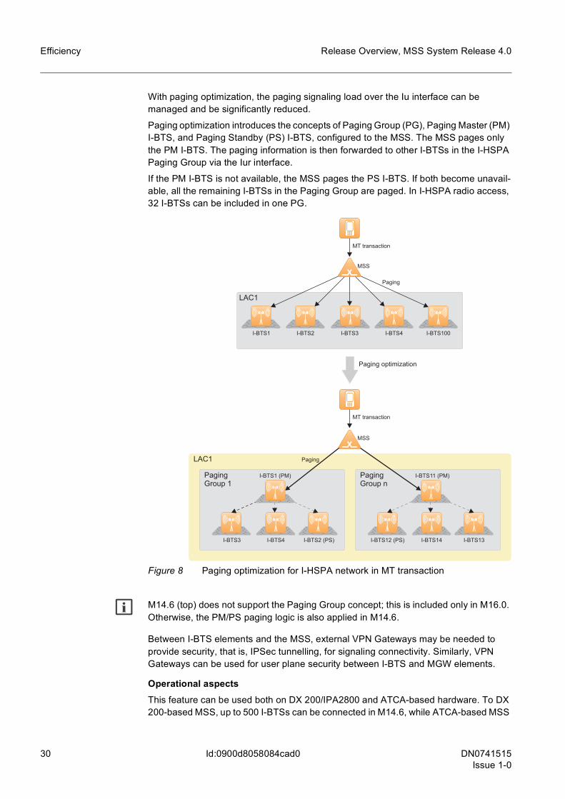
With paging optimization, the paging signaling load over the Iu interface can be managed and be significantly reduced.
Paging optimization introduces the concepts of Paging Group (PG), Paging Master (PM) I-BTS, and Paging Standby (PS) I-BTS, configured to the MSS. The MSS pages only the PM I-BTS. The paging information is then forwarded to other I-BTSs in the I-HSPA Paging Group via the Iur interface.
If the PM I-BTS is not available, the MSS pages the PS I-BTS. If both become unavail-able, all the remaining I-BTSs in the Paging Group are paged. In I-HSPA radio access, 32 I-BTSs can be included in one PG.
Figure 8 Paging optimization for I-HSPA network in MT transaction
g M14.6 (top) does not support the Paging Group concept; this is included only in M16.0. Otherwise, the PM/PS paging logic is also applied in M14.6.
Between I-BTS elements and the MSS, external VPN Gateways may be needed to provide security, that is, IPSec tunnelling, for signaling connectivity. Similarly, VPN Gateways can be used for user plane security between I-BTS and MGW elements.
Operational aspectsThis feature can be used both on DX 200/IPA2800 and ATCA-based hardware. To DX 200-based MSS, up to 500 I-BTSs can be connected in M14.6, while ATCA-based MSS
I-BTS1 I-BTS100I-BTS4I-BTS3I-BTS2
LAC1
MSS
Paging
MT transaction
Paging optimization
PagingGroup 1
MSS
Paging
I-BTS3 I-BTS2 (PS)I-BTS4
I-BTS1 (PM)
I-BTS12 (PS) I-BTS13I-BTS14
I-BTS11 (PM)PagingGroup n
LAC1
MT transaction
DN0741515Issue 1-0
31
Release Overview, MSS System Release 4.0 Efficiency
Id:0900d8058084cad0
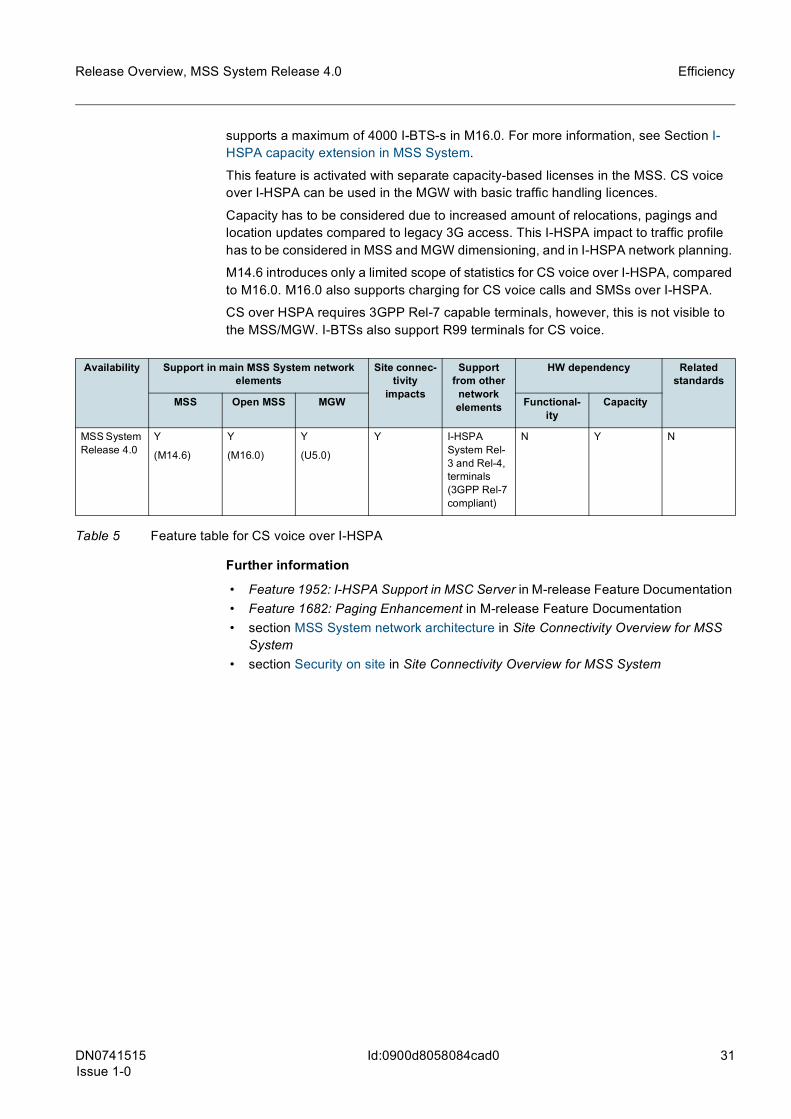
supports a maximum of 4000 I-BTS-s in M16.0. For more information, see Section I-HSPA capacity extension in MSS System.
This feature is activated with separate capacity-based licenses in the MSS. CS voice over I-HSPA can be used in the MGW with basic traffic handling licences.
Capacity has to be considered due to increased amount of relocations, pagings and location updates compared to legacy 3G access. This I-HSPA impact to traffic profile has to be considered in MSS and MGW dimensioning, and in I-HSPA network planning.
M14.6 introduces only a limited scope of statistics for CS voice over I-HSPA, compared to M16.0. M16.0 also supports charging for CS voice calls and SMSs over I-HSPA.
CS over HSPA requires 3GPP Rel-7 capable terminals, however, this is not visible to the MSS/MGW. I-BTSs also support R99 terminals for CS voice.
Further information
• Feature 1952: I-HSPA Support in MSC Server in M-release Feature Documentation • Feature 1682: Paging Enhancement in M-release Feature Documentation • section MSS System network architecture in Site Connectivity Overview for MSS
System • section Security on site in Site Connectivity Overview for MSS System
Availability Support in main MSS System network elements
Site connec-tivity
impacts
Support from other
network elements
HW dependency Related standards
MSS Open MSS MGW Functional-ity
Capacity
MSS System Release 4.0
Y
(M14.6)
Y
(M16.0)
Y
(U5.0)
Y I-HSPA System Rel-3 and Rel-4, terminals (3GPP Rel-7 compliant)
N Y N
Table 5 Feature table for CS voice over I-HSPA
32 DN0741515Issue 1-0
Release Overview, MSS System Release 4.0
Id:0900d805808822c8
6.2 I-HSPA capacity extension in MSS SystemShort descriptionFrom MSS System Release 4.0, up to 4000 I-BTS signaling connections can be handled by an MSS.
Operator benefitWith this feature, the operators can connect eight times more I-BTSs to an MSS on the control plane.
Implementation in earlier releasesPresently, 500 I-BTS signaling connections are supported per MSS. However, large I-HSPA networks may see rising need to extend the current connectivity capacity for I-BTSs.
MSS SR4.0 implementationThis feature covers the I-BTS-related capacity enhancement in the MSS System up to 4000 I-BTSs per MSS.
I-HSPA is a PS optimized flat architecture for both RAN and packet core as standardized by 3GPP Rel-7. By flattening the architecture, I-HSPA removes the bottlenecks from the network unleashing the whole Air-interface capability for growing data traffic needs.
Because in I-HSPA architecture, the RNC functionality has been moved closer to the radio interface, that is, into I-HSPA BTSs (I-BTSs), the main architectural difference compared to normal 3G access is that there can be thousands of RNC like I-BTSs to be handled by one MSS.
For an overview of I-HSPA architecture, see Figure I-HSPA architecture with MSS System and packet core network.
Operational aspectsI-HSPA capacity extension is applicable for ATCA-based MSS, as well as for IPA2800-based MGW. However, support in DX 200 HW-based MSS will only be available in later MSS System releases.
This functionality is activated with a separate license in the MSS.
Availability Support in main MSS System network elements
Site connec-tivity
impacts
Support from other
network elements
HW dependency Related standards
MSS Open MSS MGW Functional-ity
Capacity
MSS System Release 4.0
N
(in later release)
Y
(M16.0 Late)
U5.0 EP Y I-HSPA System Rel-2 and Rel-3
N Y 3GPP TS 25.413, 25.999
Table 6 Feature table for I-HSPA capacity extension in MSS System
DN0741515Issue 1-0
33
Release Overview, MSS System Release 4.0
Id:0900d8058084cb9a
6.3 Support for 3GPP SIP-I TFO -TrFO - supplementary servicesShort descriptionMSS SR4.0 supports a 3GPP SDP indicator - Out of Band Transcoder Control (OoBTC) parameter - for supplementary service-related SIP-I call cases too. OoBTC enables flexible SDP-based codec negotiation and Mid-call Codec Negotiation (MCCN).
Operator benefitSDP-based codec negotiation can be used in between MSSs or from the MSS towards any IETF-based equipment for supplementary call cases if 3GPP OoBTC indicator is used in the SDP. The operator can have the same TrFO features in SIP-I codec nego-tiation for almost all supplementary service-related call cases as in BICC codec negoti-ation.
Implementation in earlier releasesIn MSS SR3.3, support of codec negotiation and MCCN over SIP-I is available for basic call cases only, during setup phase.
MSS SR4.0 implementationMSS System Release 4.0 supports 3GPP SIP-I TFO-TrFO with using 3GPP-defined OoBTC indicator in SDP offer/answer exchanges in supplementary service call cases. This functionality allows the use of TrFO codec negotiation (CN) and Mid-call Codec Negotiation (MCCN) mechanisms in networks where SIP-I is used for carrying signaling between MSSs instead of BICC. This functionality can be used between MSSs and between MSC Server and other IETF-standards-compliant network equipment if 3GPP OoBTC SDP indicator is used.
TrFO/TFO interworking and related features are used for minimizing transcoder resource usage in speech transmission between end users.
TrFO/TFO ensures that codec configuration is negotiated properly during the call estab-lishment phase and then modified on the fly if required due to, for example, supplemen-tary services.
The MSS System supports 3GPP SIP-I TFO-TrFO interworking for the following supple-mentary services:
• Call forwarding • Call waiting • Intermediate call • Call alternation • Call transfer, Call transfer recall • Multiparty (MPTY)
This functionality does not cover other SIP interface profiles of MSS such as SIP in NVS or MGCF roles.
Operational aspectsAlthough this functionality is not controlled by license, it can be used only through optional public features such as NVS/SIP-I and AMR TFO.
34 DN0741515Issue 1-0
Release Overview, MSS System Release 4.0
Id:0900d8058084cb9a
Further information
• Feature 1335: Speech Transmission Optimization in M-release Feature Documen-tation
Availability Support in main MSS System network elements
Site connec-tivity
impacts
Support from other
network elements
HW dependency Related standards
MSS Open MSS MGW Functional-ity
Capacity
MSS System Release 4.0
Y
(M14.6)
Y
(M16.0)
N/A N No support required
N N 3GPP TS 23.231, 29.231, 23.153
Table 7 Feature table for 3GPP SIP-I TFO -TrFO - supplementary services
DN0741515Issue 1-0
35
Release Overview, MSS System Release 4.0
Id:0900d8058084cad2
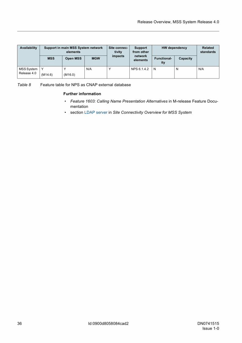
6.4 NPS as CNAP external databaseShort descriptionFrom M14.6 onwards the MSS is able to utilize an external database for Calling Name Presentation (CNAP) service via LDAP interface.
MSS System supports Nokia Siemens Networks Profile Server (NPS) to be used as Calling Name Presentation (CNAP) external database.
Operator benefitWith this feature, the operator can reuse existing investment into NPS for another purpose, therefore saving CAPEX and OPEX.
For customers who do not currently have NPS deployed in their network, this feature provides a full, easy-to-integrate CNAP solution.
Implementation in earlier releasesCurrently, Nokia Siemens Networks has an MSS-internal solution. However, each external CNAP deployment needs separate integration and verification.
NPS is a proven subscriber data management and profile resolution database for NVS, for managing service subscriptions and access to various data services. Therefore, NPS could also be used as Name Database for CNAP.
MSS SR4.0 implementationFrom MSS SR4.0, the MSS can use the Nokia Siemens Networks Profile Server (NPS) as external CNAP database.
Calling Name Presentation (CNAP) supplementary service requires an external Name Database that provides the name of the calling party upon MSS query, either in received or initiated calls. The CNAP database stores the textual presentation of name that is linked to given number used as Calling Line Identity.
Nokia Siemens Networks Profile Server (NPS) is an LDAP directory product that offers carrier grade, scalable database for different services, such as VoIP provided by NVS. Using LDAP interface is a feasible way also to retrieve CNAP-related information for each call.
CNAP-related information stored in NPS is defined in a specific LDAP schema that is used both by the MSS and the NPS to understand content in the same way. The schema describes typed data fields that have to exist in LDAP hierarchy.
Both A-party and B-party CNAP services can be implemented with NPS.
In a call setup, the textual information stored into LDAP and associated for calling line identity (MSISDN) of the calling subscriber is shown to called subscriber while the phone is alerting.
Operational aspectsThis feature is activated with a separate license in the MSS. The LDAP interface config-uration is described in the MSS product documentation.
The same NPS can be used as CNAP external database and as LDAP directory for NVS at the same time. However, one MSS/NVS can establish connections only to one LDAP server, irrespective of how many LDAP services it uses.
This functionality can also work with NVS in incoming VoIP (SIP) sessions.
36 DN0741515Issue 1-0
Release Overview, MSS System Release 4.0
Id:0900d8058084cad2
Further information
• Feature 1603: Calling Name Presentation Alternatives in M-release Feature Docu-mentation
• section LDAP server in Site Connectivity Overview for MSS System
Availability Support in main MSS System network elements
Site connec-tivity
impacts
Support from other
network elements
HW dependency Related standards
MSS Open MSS MGW Functional-ity
Capacity
MSS System Release 4.0
Y
(M14.6)
Y
(M16.0)
N/A Y NPS 6.1.4.2 N N N/A
Table 8 Feature table for NPS as CNAP external database
DN0741515Issue 1-0
37
Release Overview, MSS System Release 4.0
Id:0900d8058084cafe
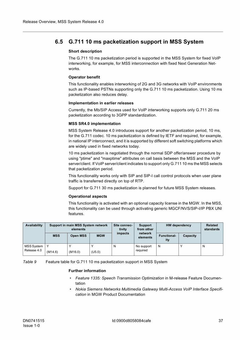
6.5 G.711 10 ms packetization support in MSS SystemShort descriptionThe G.711 10 ms packetization period is supported in the MSS System for fixed VoIP interworking, for example, for MSS interconnection with fixed Next Generation Net-works.
Operator benefitThis functionality enables interworking of 2G and 3G networks with VoIP environments such as IP-based PSTNs supporting only the G.711 10 ms packetization. Using 10 ms packetization also reduces delay.
Implementation in earlier releasesCurrently, the Mb/SIP Access used for VoIP interworking supports only G.711 20 ms packetization according to 3GPP standardization.
MSS SR4.0 implementationMSS System Release 4.0 introduces support for another packetization period, 10 ms, for the G.711 codec. 10 ms packetization is defined by IETF and required, for example, in national IP interconnect, and it is supported by different soft switching platforms which are widely used in fixed networks today.
10 ms packetization is negotiated through the normal SDP offer/answer procedure by using "ptime" and "maxptime" attributes on call basis between the MSS and the VoIP server/client. If VoIP server/client indicates to support only G.711 10 ms the MSS selects that packetization period.
This functionality works only with SIP and SIP-I call control protocols when user plane traffic is transferred directly on top of RTP.
Support for G.711 30 ms packetization is planned for future MSS System releases.
Operational aspectsThis functionality is activated with an optional capacity license in the MGW. In the MSS, this functionality can be used through activating generic MGCF/NVS/SIP-I/IP PBX UNI features.
Further information
• Feature 1335: Speech Transmission Optimization in M-release Feature Documen-tation
• Nokia Siemens Networks Multimedia Gateway Multi-Access VoIP Interface Specifi-cation in MGW Product Documentation
Availability Support in main MSS System network elements
Site connec-tivity
impacts
Support from other
network elements
HW dependency Related standards
MSS Open MSS MGW Functional-ity
Capacity
MSS System Release 4.0
Y
(M14.6)
Y
(M16.0)
Y
(U5.0)
N No support required
N Y N
Table 9 Feature table for G.711 10 ms packetization support in MSS System
38 DN0741515Issue 1-0
Release Overview, MSS System Release 4.0
Id:0900d8058084cb00
6.6 CS Fallback Phase 1 in MSS SystemShort descriptionThe CS Fallback functionality provides a seamless voice service and enables the reuse of the existing CS core networks for voice services when the subscriber is attached to E-UTRAN/EPS. This means that the introduction of LTE/EPS can occur without the implementation of voice over IP (VoIP) for primary voice service.
The CS Fallback functionality is introduced in two phases. In phase 1, the SMS proce-dure over the SGs interface and its supporting functions are implemented. This service enables LTE introduction as a data only type of network and makes the initial LTE investments smaller.
Operator benefitThe primary LTE voice service is voice over IP and the messaging service is SMS over IP. Where LTE/EPS deployments are geographically sparse and do not provide full cov-erage, the handovers are huge in number and are cumbersome - VoIP deployment is not the optimal solution.
Phase 1 implementation of the CS Fallback offers the following benefits:
• The existing SMS delivery framework can be reused, for example, to deliver Over The Air (OTA) configuration messages to the LTE attached terminals.
• SMS billing introduces E-UTRAN-specific identifiers into the SGs interface and CDRs.
• Support of concatenated SMS over the SGs interface is provided.
The full support of CS Fallback functionality, to be implemented in a coming release, offers the following benefits:
• seamless voice service • reuse of already deployed circuit switched domain for voice services • reuse of the MSC Server’s functionalities and investments • deployment of the latest technology without the requirement to use VoIP • can be used in parallel with or prior to the introduction of the IMS-based VoIP
solution
Implementation in earlier releasesThe current user equipment configurations prevent the user equipment (UE) from being simultaneously camped both on GERAN/UTRAN and E-UTRAN radio networks. This means that the UE can either be camped on E-UTRAN or on GERAN/UTRAN.
MSS SR4.0 implementation3GPP defines the concept of SMS over SGs and Circuit-Switched (CS) Fallback for the Evolved Packet System (EPS).
The SMS procedure over the SGs interface is executed without any fallback to the 2G/3G network. It is handled over the LTE radio access network. Mobile-originated (MO) SMS and Mobile-terminated (MT) SMS are delivered through Non-Access Stratum Signaling (NAS) between the UE and the MME, and over the SGs interface between the MME and the MSC Server. Every MSS can potentially be configured to every MME. For Phase 1, the implementation of a dedicated MSS is recommended.
DN0741515Issue 1-0
39
Release Overview, MSS System Release 4.0
Id:0900d8058084cb00
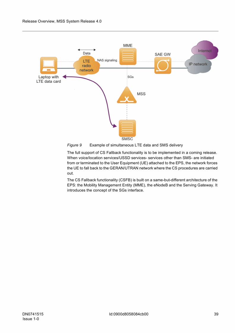
Figure 9 Example of simultaneous LTE data and SMS delivery
The full support of CS Fallback functionality is to be implemented in a coming release. When voice/location services/USSD services- services other than SMS- are initiated from or terminated to the User Equipment (UE) attached to the EPS, the network forces the UE to fall back to the GERAN/UTRAN network where the CS procedures are carried out.
The CS Fallback functionality (CSFB) is built on a same-but-different architecture of the EPS: the Mobility Management Entity (MME), the eNodeB and the Serving Gateway. It introduces the concept of the SGs interface.
40 DN0741515Issue 1-0
Release Overview, MSS System Release 4.0
Id:0900d8058084cb00
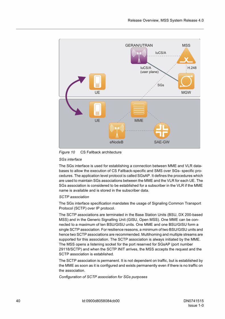
Figure 10 CS Fallback architecture
SGs interface
The SGs interface is used for establishing a connection between MME and VLR data-bases to allow the execution of CS Fallback-specific and SMS over SGs- specific pro-cedures. The application level protocol is called SGsAP. It defines the procedures which are used to maintain SGs associations between the MME and the VLR for each UE. The SGs association is considered to be established for a subscriber in the VLR if the MME name is available and is stored in the subscriber data.
SCTP association
The SGs interface specification mandates the usage of Signaling Common Transport Protocol (SCTP) over IP protocol.
The SCTP associations are terminated in the Base Station Units (BSU, DX 200-based MSS) and in the Generic Signalling Unit (GISU, Open MSS). One MME can be con-nected to a maximum of ten BSU/GISU units. One MME and one BSU/GISU form a single SCTP association. For resilience reasons, a minimum of two BSU/GISU units and hence two SCTP associations are recommended. Multihoming and multiple streams are supported for this association. The SCTP association is always initiated by the MME. The MSS opens a listening socket for the port reserved for SGsAP (port number 29118/SCTP) and when the SCTP INIT arrives, the MSS accepts the request and the SCTP association is established.
The SCTP association is permanent. It is not dependent on traffic, but is established by the MME as soon as it is configured and exists permanently even if there is no traffic on the association.
Configuration of SCTP association for SGs purposes
DN0741515Issue 1-0
41
Release Overview, MSS System Release 4.0
Id:0900d8058084cb00
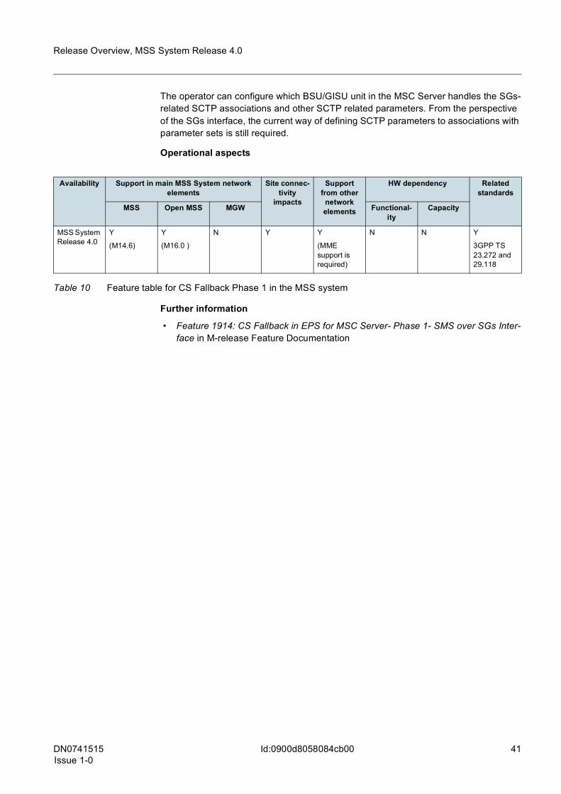
The operator can configure which BSU/GISU unit in the MSC Server handles the SGs-related SCTP associations and other SCTP related parameters. From the perspective of the SGs interface, the current way of defining SCTP parameters to associations with parameter sets is still required.
Operational aspects
Further information
• Feature 1914: CS Fallback in EPS for MSC Server- Phase 1- SMS over SGs Inter-face in M-release Feature Documentation
Availability Support in main MSS System network elements
Site connec-tivity
impacts
Support from other
network elements
HW dependency Related standards
MSS Open MSS MGW Functional-ity
Capacity
MSS System Release 4.0
Y
(M14.6)
Y
(M16.0 )
N Y Y
(MME support is required)
N N Y
3GPP TS 23.272 and 29.118
Table 10 Feature table for CS Fallback Phase 1 in the MSS system
42 DN0741515Issue 1-0
Release Overview, MSS System Release 4.0
Id:0900d805808632be
6.7 VLR backup solution in MSS SystemShort descriptionThe VLR Backup (VLR BU) solution provides immediate mobile terminating service con-tinuation after a VLR restart or MSS failure when visiting subscribers’ data have been lost. This is enabled by storing the subscribers’ data on an external network entity in order to lower the transaction time and signaling link load while reading data back after a system or VLR restart. The VLR is connected to a Backup Server with a proprietary Sz interface.
Operator benefitWithout this feature, recovering visiting subscribers’ data not only takes a long time but also causes a considerable extra load in the system, especially in the case of high capacity VLRs with several millions of subscribers.
The VLR BU solution provides the following benefits for the operator:
• immediate mobile terminating service continuation after losing visiting subscribers’ data
• prevention of radio network overload impact caused by the ‘search’ function • preventing the VLR, HLR and signalling links from the load peak after a system
restart • intensify reliable network brand among end users • roaming subscribers are not lost after a system restart • improved end user service availability • seamless network upgrade without end user disturbance • complete geographical redundancy support on top of MSS pooling • enhancement to the N+X redundant MSS solution • enhancement to the Multipoint A/Iu features • fast restoration of subscriber data to the redundant network element
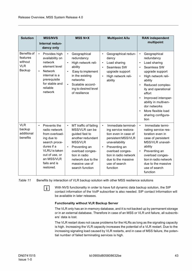
The benefits of the VLR backup solution can also be viewed in interaction with other MSS resilience solutions:
DN0741515Issue 1-0
43
Release Overview, MSS System Release 4.0
Id:0900d805808632be
g With NVS functionality in order to have full dynamic data backup solution, the SIP contact information of the VoIP subscriber is also needed. SIP contact Information will be available in later releases.
Functionality without VLR Backup ServerThe VLR only has an in-memory database, and it is not backed up by permanent storage or in an external database. Therefore in case of an MSS or VLR unit failure, all subscrib-ers’ data is lost.
The VLR restart does not cause problems for the HLRs as long as the signaling capacity is high. Increasing the VLR capacity increases the potential of a VLR restart. Due to the increasing signaling load caused by VLR restarts, and in case of MSS failure, the poten-tial number of failed terminating services is high.
Solution MSS/NVSInternal redun-
dancy only
MSS N+X Multipoint A/Iu RAN independent multipoint
Benefits of features without VLR Backup
• Provides high availability on network element level
• Network internal is a prerequisite for stable and reliable network
• Geographical redundancy
• High network reli-ability
• Easy to implement in the existing networks
• Scalable accord-ing to desired level of resilience
• Geographical redun-dancy
• Load sharing • Seamless SW
upgrade support • High network reli-
ability
• Geographical redundancy
• Load sharing • Seamless SW
upgrade support • High network reli-
ability • Reduced complex-
ity and operational effort
• Improved interoper-ability in multiven-dor networks
• More flexible load sharing configura-tion
VLR backup additional benefits
• Prevents the radio network from overload-ing due to search proce-dures if a VLRU is taken out of use, or an MSS/VLR fails and is restored.
• MT traffic of failing MSS/VLR can be guided fast to another redundant MSS/VLR
• Preventing an overload conges-tion in radio network due to the massive use of search function
• Immediate terminat-ing service restora-tion even in case of persistent MSS/VLR unavailability
• Preventing an overload conges-tion in radio network due to the massive use of search function
• Immediate termi-nating service res-toration even in case of persistent MSS/VLR unavail-ability
• Preventing an overload conges-tion in radio network due to the massive use of search function
Table 11 Benefits by interaction of VLR backup solution with other MSS resilience solutions

44 DN0741515Issue 1-0
Release Overview, MSS System Release 4.0
Id:0900d805808632be
MSS SR4.0 implementationIn the case of MSS restart or any VLR unit, all subscribers’ data must be restored from the HLR. In mobile-terminated cases, the subscriber must be paged for. In such cases, there is a high load on the MAP interface towards the HLR and on the radio network.
The VLR backup solution stores the subscribers’ data on an external network entity, the VLR Backup Server. The transaction time and signaling link load are lowered when reading data back after an MSS or VLR restart.
The VLR Backup Server has the following main tasks:
• it handles the read, delete, write and supervision (heartbeat) messages arriving from the VLRUs through the Sz interface
• it reads/writes the backup database • it provides information for statistics
The VLR backup solution is illustrated in the following figure:
Figure 11 VLR backup functionality
The VLR Backup Server is a memory Database (DB) which is periodically copied to disk. Due to the large amount of information, not the whole database is copied to the disk; therefore not all the changes are replicated in the VLR Backup Server. Each time the VLR Backup Server is activated it writes a part of its stored data to the DB. The memory DB is partitioned for parallel accesses. Each partition has a counter, which describes the changes that took place in that particular partition since the last time it was written to the disk. To minimize the number of changes that are not stored in the memory, multiple par-titions can be written at the same time. The unsaved changes are only problematic when the VLRs and the VLR Backup Server are restarted at the same time.
The following items are backed up:
• International Mobile Subscriber Identity (IMSI) • location area identification (LAI) - the subscriber’s last known location • radio access type - GSM/UMTS/LTE • last active date the timestamp of the latest subscriber activity

DN0741515Issue 1-0
45
Release Overview, MSS System Release 4.0
Id:0900d805808632be
• mobile not reachable (MNR) flag - indicates that the subscriber has a pending short message due to unavailability
• VLR address - the address of the VLR that inserted the data to the backup server • SGSN association - indicates if the subscriber is available through the Gs interface • MME association - indicates if the subscriber is available through the SGs interface • IMSI detach flag - indicates if the subscriber is attached for CS services
If the VLR Backup Server is restarted when the VLRs are online, the internal DB of the VLR Backup Server is subsequently synchronized with the VLRs. The timing depends on the VLR’s periodic update interval.
The High Availability (HA) solution also helps to avoid data loss, there are two servers running at the same time. Only one of them has got a public IP address. This server, which has a public IP address, forwards the VLR’s requests to the other, so that its memory is mirrored. In case the VLR with the public IP address fails, the public IP address is moved to the other server and the VLR has to reconnect and continues the work with the other server.
Interworking with other features:
• Multipoint A/IuThe Multipoint solution introduces the concept of pool areas, enabled by the routing mechanism in the RAN nodes, or optionally in the MGW. A pool area is comparable to an MSC/MSS service area as a collection of one or more RAN node service areas. The difference between a pool area and a MSC/MSS service area, is that a pool area is served by multiple MSC/MSSs in parallel, sharing traffic between them.With the VLR backup feature it is possible to maintain full Mobile Terminated (MT) availability in the pool area configuration, if the MSC/MSS, which is serving the sub-scriber, becomes available. When the HLR is unable to contact the failed MSS/VLR to establish an MT transaction, the signaling request can be automatically rerouted to an alternate pool MSS. The alternate pool MSS fetches the key subscriber data from the VLR Backup Server and continues the transaction as normal. The pool MSS’s awareness of MT services is provided on the SCCP layer in the HLR or STP. The VLR BU feature manages the automatic GT re-routing operations (including Cancel Location) and load balancing signaling. Alternately, the operator can manually re-configure GT addressing. Automatic re-routing can result in VLR-HLR interface overload during peak use if the interface is not dimensioned to cope with the additional load.If the HLR (or the Signaling Transfer Point) supports re-routing of the Provide Roaming Number (PRN) pre-paging functionality to the replacement pool MSS/VLR, the first MT transaction (without preceding originating transaction) will succeed. If re-routing of the PRN is not supported, then the first terminating transaction may fail, but the subsequent ones will succeed.
• MSS N+X redundancyThe redundant N+X MSS solution protects several active MSSs with a redundant MSS (RMSS). If there are a large number of MSSs to be protected, or the geograph-ical area covered by the MSSs is large, several redundant MSSs may be required. When a protected MSS fails, the RMSS should provide the same services. At the time of failure, on-going calls are discontinued. Subscribers registered under the failed MSS/VLR are out-of-service and unreachable until the RMSS is active
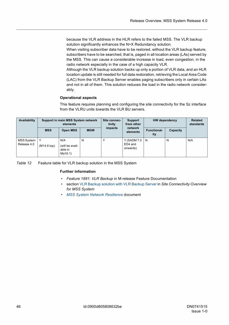
46 DN0741515Issue 1-0
Release Overview, MSS System Release 4.0
Id:0900d805808632be
because the VLR address in the HLR refers to the failed MSS. The VLR backup solution significantly enhances the N+X Redundancy solution.When visiting subscriber data have to be restored, without the VLR backup feature, subscribers have to be searched, that is, paged in all location areas (LAs) served by the MSS. This can cause a considerable increase in load, even congestion, in the radio network especially in the case of a high capacity VLR.Although the VLR backup solution backs up only a portion of VLR data, and an HLR location update is still needed for full data restoration, retrieving the Local Area Code (LAC) from the VLR Backup Server enables paging subscribers only in certain LAs and not in all of them. This solution reduces the load in the radio network consider-ably.
Operational aspectsThis feature requires planning and configuring the site connectivity for the Sz interface from the VLRU units towards the VLR BU servers.
Further information
• Feature 1881: VLR Backup in M-release Feature Documentation • section VLR Backup solution with VLR Backup Server in Site Connectivity Overview
for MSS System • MSS System Network Resilience document
Availability Support in main MSS System network elements
Site connec-tivity
impacts
Support from other
network elements
HW dependency Related standards
MSS Open MSS MGW Functional-ity
Capacity
MSS System Release 4.0
Y
(M14.6 top)
N/A
(will be avail-able in Ma16.1)
N Y Y (SADM 7.0 ED4 and onwards)
N N N/A
Table 12 Feature table for VLR backup solution in the MSS System
DN0741515Issue 1-0
47
Release Overview, MSS System Release 4.0
Id:0900d8058081704d
6.8 CNPS-based Dynamic TDM Circuit BalancerShort descriptionThe distribution of subscribers from a BSC to the pooled MSSs becomes uneven over time. However, CNPS can reallocate the A interface resources between Circuit Groups in the same physical MGW based on the utilization level.
Operator benefitThe CNPS solution provides the operators with the following benefits: • Provides a combination of end-to-end resiliency with efficient use of TDM resources.
Less redundant TDM A and Ater interface capacity is required to deliver a higher level of resiliency.
• Operators can offer subscribers an improved user experience. • Offers the opportunity to dynamically re-employ TDM A and Ater interface capacity
that is reserved for the use of a pooled MSS that is unavailable.
MSS SR4.0 implementationEach BSC has a separate TDM Circuit Group (CGR) controlled by each pooled MSS. The CGRs are connected to the same physical MGW, but different virtual MGWs (vMGW) that are controlled by the corresponding pool MSS. Utilization of the configured dedicated resources can become uneven over time. Some CGRs are overloaded, while others have spare capacity.
CNPS can dynamically re-allocate A or Ater interface circuit resources between MSSs based up on circuit load. Circuit load may differ simply because of distortions in sub-scriber allocation from BSCs to MSSs that occur over time, or because a particular pooled MSS becomes unavailable. Reallocation can either be automatic, or subject to the operators’ approval.This feature can be used simultaneously with BSC re-homing.
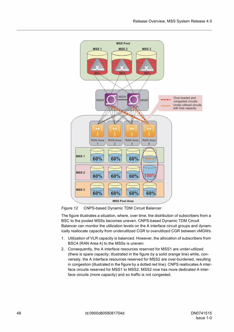
48 DN0741515Issue 1-0
Release Overview, MSS System Release 4.0
Id:0900d8058081704d
Figure 12 CNPS-based Dynamic TDM Circuit Balancer
The figure illustrates a situation, where, over time, the distribution of subscribers from a BSC to the pooled MSSs becomes uneven. CNPS-based Dynamic TDM Circuit Balancer can monitor the utilization levels on the A interface circuit groups and dynam-ically reallocate capacity from underutilized CGR to overutilized CGR between vMGWs.
1. Utilization of VLR capacity is balanced. However, the allocation of subscribers from BSC4 (RAN Area 4) to the MSSs is uneven.
2. Consequently, the A interface resources reserved for MSS1 are under-utilized (there is spare capacity; illustrated in the figure by a solid orange line) while, con-versely, the A interface resources reserved for MSS2 are over-burdened, resulting in congestion (illustrated in the figure by a dotted red line). CNPS reallocates A inter-face circuits reserved for MSS1 to MSS2. MSS2 now has more dedicated A inter-face circuits (more capacity) and so traffic is not congested.
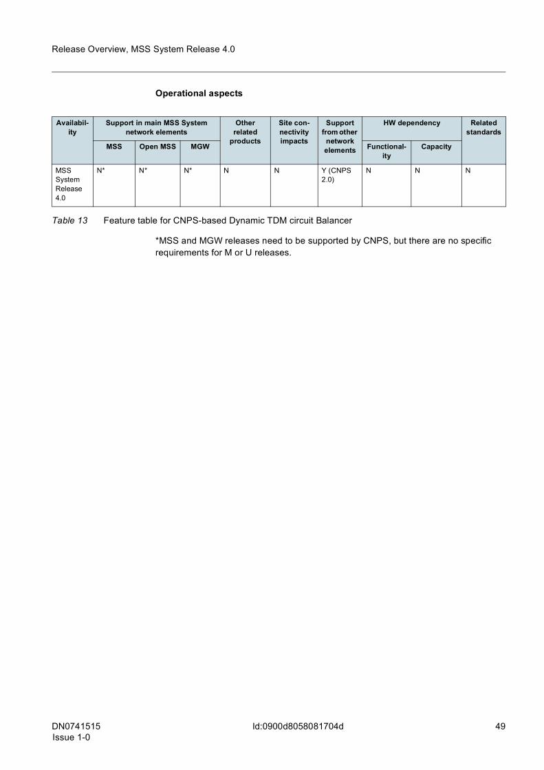
DN0741515Issue 1-0
49
Release Overview, MSS System Release 4.0
Id:0900d8058081704d
Operational aspects
*MSS and MGW releases need to be supported by CNPS, but there are no specific requirements for M or U releases.
Availabil-ity
Support in main MSS System network elements
Other related
products
Site con-nectivity impacts
Support from other
network elements
HW dependency Related standards
MSS Open MSS MGW Functional-ity
Capacity
MSS System Release 4.0
N* N* N* N N Y (CNPS 2.0)
N N N
Table 13 Feature table for CNPS-based Dynamic TDM circuit Balancer

50 DN0741515Issue 1-0
Release Overview, MSS System Release 4.0
Id:0900d80580816fc3
6.9 CNPS-based VLR load balancing for MSS poolingShort descriptionVisitor Location Register (VLR) load balancing for MSS pooling can automatically ensure that the subscriber load is evenly distributed across the pooled MSSs. VLR load balancing application is part of Nokia Siemens Networks’ Core Networks Productivity Suite (CNPS), which uses Service Oriented Architecture (SOA) to connect to the network layer, and to be capable of independently and automatically reconfiguring network elements based on user-defined settings.
Operator benefitVLR load balancer offers the following benefits:
• reduced Operating Expenditure (OPEX) because Operation and Maintenance (O&M) is simplified
• reduced risk of unintentional pool MSS overload • ensures balanced load for MSSs handling both pooled and non-pooled BSCs/RNCs • makes it simpler to return to the situation before Load Balancing was necessitated,
for example because of the failure of a pool MSS.
Implementation in earlier releasesThe RAN Independent Multipoint lu/A features, enable the subscriber and the traffic load to be distributed between a number of pool MSSs. However, over the time, or because of abnormal occurrences, for example the failure of a pool MSS, load may become unbalanced.
MSS SR4.0 implementationBuilding and maintaining load balancing between pooled MSSs requires significant planning, implementation, monitoring and prompt configuration changes to achieve optimal load balancing.
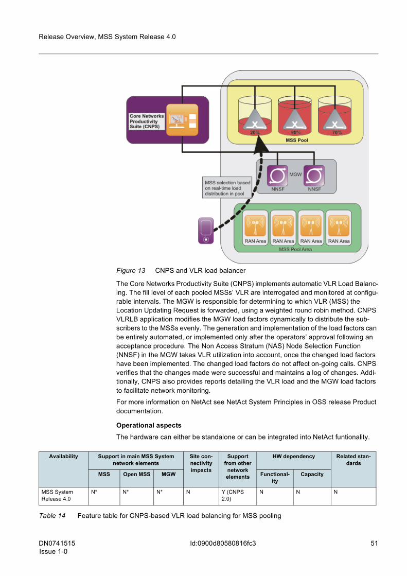
DN0741515Issue 1-0
51
Release Overview, MSS System Release 4.0
Id:0900d80580816fc3
Figure 13 CNPS and VLR load balancer
The Core Networks Productivity Suite (CNPS) implements automatic VLR Load Balanc-ing. The fill level of each pooled MSSs’ VLR are interrogated and monitored at configu-rable intervals. The MGW is responsible for determining to which VLR (MSS) the Location Updating Request is forwarded, using a weighted round robin method. CNPS VLRLB application modifies the MGW load factors dynamically to distribute the sub-scribers to the MSSs evenly. The generation and implementation of the load factors can be entirely automated, or implemented only after the operators’ approval following an acceptance procedure. The Non Access Stratum (NAS) Node Selection Function (NNSF) in the MGW takes VLR utilization into account, once the changed load factors have been implemented. The changed load factors do not affect on-going calls. CNPS verifies that the changes made were successful and maintains a log of changes. Addi-tionally, CNPS also provides reports detailing the VLR load and the MGW load factors to facilitate network monitoring.
For more information on NetAct see NetAct System Principles in OSS release Product documentation.
Operational aspectsThe hardware can either be standalone or can be integrated into NetAct funtionality.
Availability Support in main MSS System network elements
Site con-nectivity impacts
Support from other
network elements
HW dependency Related stan-dards
MSS Open MSS MGW Functional-ity
Capacity
MSS System Release 4.0
N* N* N* N Y (CNPS 2.0)
N N N
Table 14 Feature table for CNPS-based VLR load balancing for MSS pooling
52 DN0741515Issue 1-0
Release Overview, MSS System Release 4.0
Id:0900d80580816fc3
*MSS and MGW releases need to be supported by CNPS, but there are no specific requirements for M or U releases.
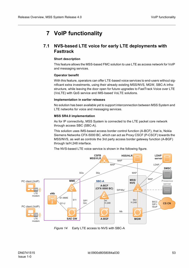
DN0741515Issue 1-0
53
Release Overview, MSS System Release 4.0 VoIP functionality
Id:0900d8058084a030
7 VoIP functionality
7.1 NVS-based LTE voice for early LTE deployments with FasttrackShort descriptionThis feature allows the MSS-based FMC solution to use LTE as access network for VoIP and messaging services.
Operator benefitWith this feature, operators can offer LTE-based voice services to end-users without sig-nificant extra investments, using their already existing MSS/NVS, MGW, SBC-A infra-structure, while leaving the door open for future upgrades to FastTrack Voice over LTE (VoLTE) with QoS service and IMS-based VoLTE solutions.
Implementation in earlier releasesNo solution has been available yet to support interconnection between MSS System and LTE networks for voice and messaging services.
MSS SR4.0 implementationAs for IP connectivity, MSS System is connected to the LTE packet core network through access SBC (SBC-A).
This solution uses IMS-based access border control function (A-BCF), that is, Nokia Siemens Networks CFX-5000 BC, which can act as Proxy CSCF (P-CSCF) towards the MSS/NVS, as well as controls the 3rd party access border gateway function (A-BGF) through Ia/H.248 interface.
The NVS-based LTE voice service is shown in the following figure.
Figure 14 Early LTE access to NVS with SBC-A
MSS/NVS
MGWA-BGF
A-BCF(CFX-5000 BC)
SIP/Mw’
Mn/H.248
SBC-AMME
SAE GW
eNb
PC client (VoIP)
PC client (VoIP)
LTEmodem
LTEmodem
MAP
BICCSIP-IISUP
SMSC
Presenceserver
MAP
Mb
SIP/Gm
S11S1-MME
S1-U
HSS/HLRCSFBMSS/VLR
LDAPserver
MAP
MAP
LDAP
SGs S6a
Ia/H.248 CS CN

54 DN0741515Issue 1-0
Release Overview, MSS System Release 4.0
Id:0900d8058084a030
VoIP functionality
The following use case scenarios are supported for LTE subscribers registered to the NVS:
• Basic LTE VoIP session with NVS • Instant messaging using SIP MESSAGE & SMS interworking • SMS over IP (see also Section SMS MIME support in MSS-based FMC) • HD VoIP • SIM-based authentication (Digest-AKA) if supported by the MSS System • Supplementary services in NVS (CLIP/CLIR, CF, ECT, and so on)
In general, all possible call case scenarios are supported via 2G/3G/WLAN to LTE.
Operational aspectsNVS-based LTE voice for early LTE deployments is a generic feature in MSS SR4.0.
In addition to LTE radio and packet core networks, the following entities are needed:
• Data-centric LTE devices without integrated voice support (for example, laptop, LTE modem, and NCS)
• Nokia Siemens Networks CFX-5000 BC-based Access Session Border Controller solution
Further information
• Feature 1914: CS Fallback in EPS for MSC Server- Phase 1- SMS over SGs Inter-face in M-release Feature Documentation
• section Ready for LTE with MSS/NVS in Site Connectivity Overview for MSS System
Availability Support in main MSS System network elements
Site connec-tivity
impacts
Support from other
network elements
HW dependency Related standards
MSS Open MSS MGW Functional-ity
Capacity
MSS System Release 4.0
Y
(M14.6)
Y
(M16.0)
N/A Y
(SGsAP over SCTP MH signaling interface is needed between MME and MSS)
LTE Node-B, MME, LTE terminals, NCS 4.1
CFX-5000 BC IMS7.2
N N 3GPP 24.229
Table 15 Feature table for NVS-based LTE voice for early LTE deployments
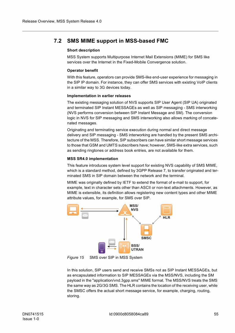
DN0741515Issue 1-0
55
Release Overview, MSS System Release 4.0
Id:0900d8058084ca89
7.2 SMS MIME support in MSS-based FMC Short descriptionMSS System supports Multipurpose Internet Mail Extensions (MIME) for SMS like services over the Internet in the Fixed-Mobile Convergence solution.
Operator benefitWith this feature, operators can provide SMS-like end-user experience for messaging in the SIP IP domain. For instance, they can offer SMS services with existing VoIP clients in a similar way to 3G devices today.
Implementation in earlier releasesThe existing messaging solution of NVS supports SIP User Agent (SIP UA) originated and terminated SIP Instant MESSAGEs as well as SIP messaging - SMS interworking (NVS performs conversion between SIP Instant Message and SM). The conversion logic in NVS for SIP messaging and SMS interworking also allows marking of concate-nated messages.
Originating and terminating service execution during normal and direct message delivery and SIP messaging - SMS interworking are handled by the present SMS archi-tecture of the MSS. Therefore, SIP subscribers can have similar short message services to those that GSM and UMTS subscribers have; however, SMS-like extra services, such as sending ringtones or address book entries, are not available for them.
MSS SR4.0 implementationThis feature introduces system level support for existing NVS capability of SMS MIME, which is a standard method, defined by 3GPP Release 7, to transfer originated and ter-minated SMS in SIP domain between the network and the terminal.
MIME was originally defined by IETF to extend the format of e-mail to support, for example, text in character sets other than ASCII or non-text attachments. However, as MIME is extensible, its definition allows registering new content types and other MIME attribute values, for example, for SMS over SIP.
Figure 15 SMS over SIP in MSS System
In this solution, SIP users send and receive SMSs not as SIP Instant MESSAGEs, but as encapsulated information to SIP MESSAGEs via the MSS/NVS, including the SM payload in the "application/vnd.3gpp.sms" MIME format. The MSS/NVS treats the SMS the same way as 2G/3G SMS. The HLR contains the location of the receiving user, while the SMSC offers the actual short message service, for example, charging, routing, storing.
MSS/NVS
HLR
SMSC
BSS/UTRAN
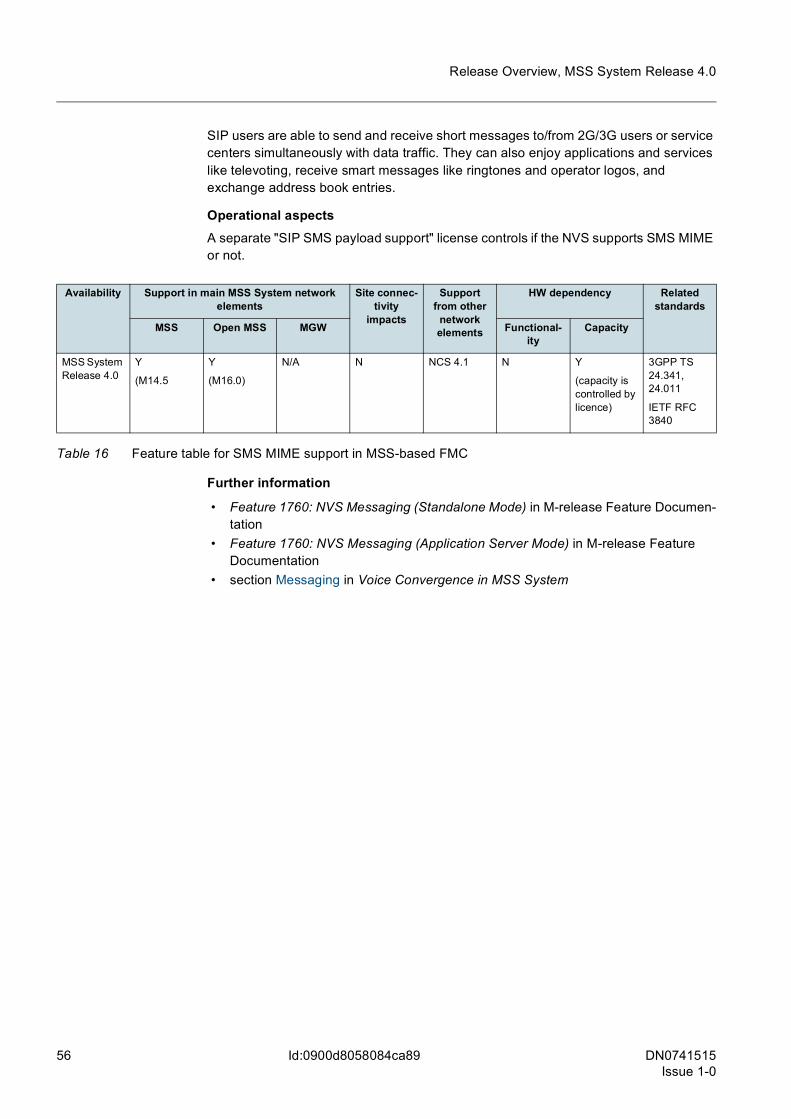
56 DN0741515Issue 1-0
Release Overview, MSS System Release 4.0
Id:0900d8058084ca89
SIP users are able to send and receive short messages to/from 2G/3G users or service centers simultaneously with data traffic. They can also enjoy applications and services like televoting, receive smart messages like ringtones and operator logos, and exchange address book entries.
Operational aspectsA separate "SIP SMS payload support" license controls if the NVS supports SMS MIME or not.
Further information
• Feature 1760: NVS Messaging (Standalone Mode) in M-release Feature Documen-tation
• Feature 1760: NVS Messaging (Application Server Mode) in M-release Feature Documentation
• section Messaging in Voice Convergence in MSS System
Availability Support in main MSS System network elements
Site connec-tivity
impacts
Support from other
network elements
HW dependency Related standards
MSS Open MSS MGW Functional-ity
Capacity
MSS System Release 4.0
Y
(M14.5
Y
(M16.0)
N/A N NCS 4.1 N Y
(capacity is controlled by licence)
3GPP TS 24.341, 24.011
IETF RFC 3840
Table 16 Feature table for SMS MIME support in MSS-based FMC
DN0741515Issue 1-0
57
Release Overview, MSS System Release 4.0
Id:0900d8058084ca5b
7.3 Colibria Presence Server for NVSShort descriptionThis functionality provides support for 3rd party presence server, Colibria, with MSS/NVS, to display presence information of end-users in VoIP terminals.
Operator benefitIn CS networks, the terminal is always "present", assuming that power is on and network coverage is wide enough. IP connectivity for VoIP terminals is mainly available at hot spots and restricted areas. Subscribers are occasionally in SIP access and this creates the need to their know presence status.
With this NVS functionality, operators can provide presence information to end-users in their VoIP terminals on other parties' availability. In this way, operators can offer com-parable usage experience for subscribers, and they can increase customer satisfaction and retain subscribers.
Operators can also apply different pricing models, for example, SIP-SIP calls to 20 parties for flat fee, since the caller can see if the other party is in SIP access.
Implementation in earlier releasesPreviously, presence service was supported by using MPM and CSDM products, which have recently been discontinued and are no longer commercially available. As part of that decision, Nokia Siemens Networks established relationship with Colibria to provide similar functionality by using their product.
MSS SR4.0 implementationMSS SR4.0 introduces end-to-end support for NVS-based VoIP presence service using Colibria Presence and XDM products, complying with Open Mobile Alliance (OMA) specifications.
Before using the presence service, the VoIP terminals are authenticated during the VoIP registration by the NVS. The NVS can also authenticate the presence-related SUB-SCRIBE and PUBLISH SIP requests.
The role of the NVS is to route SUBSCRIBE and PUBLISH SIP requests and responses between presence capable SIP clients and the presence server. The NVS also proxies the NOTIFY messages containing the presence status of requested party, as provided by presence server to the SIP user agent (UA).
The VoIP terminal capable to support OMA-based presence also uses a separate XML Configuration Access Protocol (XCAP) towards the XML Document Management (XDM) server to manipulate presence-related settings, for example, who is able to see the user's presence as well as network group lists, and so on.
The architecture of the solution is shown in the following figure.
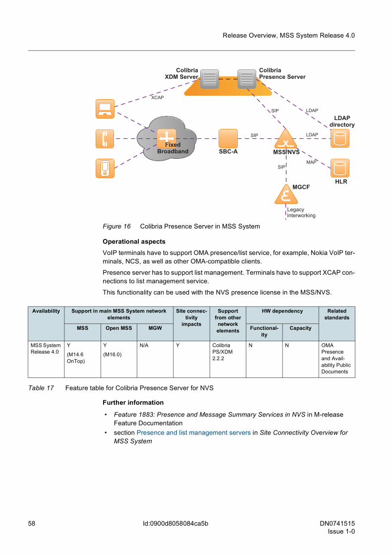
58 DN0741515Issue 1-0
Release Overview, MSS System Release 4.0
Id:0900d8058084ca5b
Figure 16 Colibria Presence Server in MSS System
Operational aspectsVoIP terminals have to support OMA presence/list service, for example, Nokia VoIP ter-minals, NCS, as well as other OMA-compatible clients.
Presence server has to support list management. Terminals have to support XCAP con-nections to list management service.
This functionality can be used with the NVS presence license in the MSS/NVS.
Further information
• Feature 1883: Presence and Message Summary Services in NVS in M-release Feature Documentation
• section Presence and list management servers in Site Connectivity Overview for MSS System
ColibriaXDM Server
SBC-A MSS/NVS
ColibriaPresence Server
HLR
LDAPdirectory
XCAP
SIP
SIP
MAP
LDAP
FixedBroadband
LDAP
SIP
Legacyinterworking
MGCF
Availability Support in main MSS System network elements
Site connec-tivity
impacts
Support from other
network elements
HW dependency Related standards
MSS Open MSS MGW Functional-ity
Capacity
MSS System Release 4.0
Y
(M14.6 OnTop)
Y
(M16.0)
N/A Y Colibria PS/XDM 2.2.2
N N OMA Presence and Avail-ability Public Documents
Table 17 Feature table for Colibria Presence Server for NVS

DN0741515Issue 1-0
59
Release Overview, MSS System Release 4.0
Id:0900d8058084a024
7.4 CK SIM authentication with 2G SIM cardShort descriptionOperators can use 2G SIM cards for Communication Key (SIM authenticated PC client) authentication; and end users can use their 2G SIM cards and mobile phone numbers in their PCs for VoIP services.
Operator benefitOperators do not have to provide separate 3G SIM cards for CK SIM authentication, which means significant OPEX savings. 2G SIM cards can also be used for reliable charging of end-users and improved service packaging.
Implementation in earlier releasesThe current version of CK solution is based on Digest authentication and key agreement (AKA) that requires a separate 3G SIM card. Currently, most 2G and 3G operators are still using 2G SIM cards only. This means that CK users can not take their current SIM card from their mobile phone and use it in a PC, for being reachable from the same number through a VoIP client. To solve this, operators have to activate 3G authentica-tion in their network and change the CK user's SIM card to a 3G version; or add a new card for the PC client and use MultiSIM (MSIM) for reachability.
Therefore, 3G authentication has meant additional cost for operators, more expensive SIM cards and unnecessary card replacement processes.
MSS SR4.0 implementationEnd users' authentication data is fetched from the Authentication Center residing in the HLR when subscribers are authenticated. This means that the client (NCS) and the reg-istrar (NVS) derive the missing parameters from 2G authentication parameters. This mechanism ensures that operators can re-use existing investment into HLR/AuC for SIM authentication for VoIP service as well. Operators can control if SIM-based authen-tication is allowed or not through LDAP configuration of subscribers.
Figure 17 CK SIM authentication in MSS System
Operational aspectsThis feature is proprietary to Nokia Siemens Networks Mobile VoIP Server (NVS) and Nokia Siemens Networks Communication Suite (NCS) application.
The current CK implementation with NCS does not support emergency sessions without prior registration.
If GSM MILENAGE algorithm is used, SECMO unit has to be installed in the HLR.
SBC-A
MSS/NVS
HLR
LDAPdirectory
MAP
LDAP
H.248
MGW
Access network
WLAN AP
TLS(opt.)
RTP
SIP
RTP
UE withDigest AKA
USB dongle withSIM reader
and PC client

60 DN0741515Issue 1-0
Release Overview, MSS System Release 4.0
Id:0900d8058084a024
Further information
• Feature 1863: SIM-based Authentication for NVS Convergence in M-release Feature Documentation
• section Security mechanisms in Voice Convergence in MSS System
Availability Support in main MSS System network elements
Site connec-tivity
impacts
Support from other
network elements
HW dependency Related standards
MSS Open MSS MGW Functional-ity
Capacity
MSS System Release 4.0
Y
(M14.6)
Y
(M16.0)
N/A N NCS 4.1 N N 3GPP TS 33.102
Table 18 Feature table for CK SIM authentication with 2G SIM card
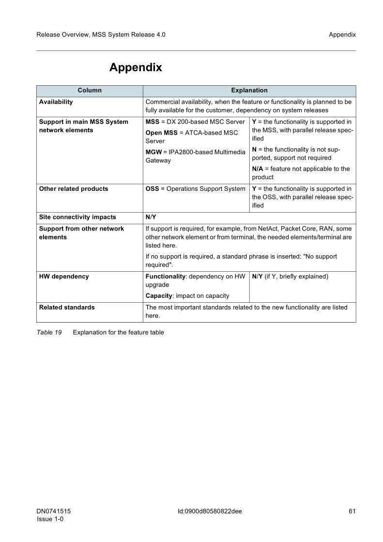
DN0741515Issue 1-0
61
Release Overview, MSS System Release 4.0 Appendix
Id:0900d80580822dee
Appendix
Column Explanation
Availability Commercial availability, when the feature or functionality is planned to be fully available for the customer, dependency on system releases
Support in main MSS System network elements
MSS = DX 200-based MSC Server
Open MSS = ATCA-based MSC Server
MGW = IPA2800-based Multimedia Gateway
Y = the functionality is supported in the MSS, with parallel release spec-ified
N = the functionality is not sup-ported, support not required
N/A = feature not applicable to the product
Other related products OSS = Operations Support System Y = the functionality is supported in the OSS, with parallel release spec-ified
Site connectivity impacts N/Y
Support from other network elements
If support is required, for example, from NetAct, Packet Core, RAN, some other network element or from terminal, the needed elements/terminal are listed here.
If no support is required, a standard phrase is inserted: "No support required".
HW dependency Functionality: dependency on HW upgrade
Capacity: impact on capacity
N/Y (if Y, briefly explained)
Related standards The most important standards related to the new functionality are listed here.
Table 19 Explanation for the feature table
62 DN0741515Issue 1-0
Release Overview, MSS System Release 4.0
Id:0900d8058082339a
Glossary
Glossary
Terms and abbreviations3GPP 3rd Generation Partnership Project
A-BCF access border control function
A-BGF access border gateway function
AMR adaptive multirate coded
ATM asynchronous transfer mode
AoIP A over IP
ATCA Advanced Telecommunication Computing Architecture
AuC authentication center
BHCA busy hour call attempt
BICC bearer-independent call control
BIWF bearer interworking function
BSC base station controller
BSS base station system
BSSAP base station system application part
BSU base station signaling unit (in MSS)
CAC connection admission control
CAPEX capital expenditure
CD change delivery
CDR charging data record
CDS Circuit-switched Data Server
CGR circuit group
CHU charging unit (in MSS and in Open MSS)
CK communication key
CLI calling line identification
CLIR calling line identification restriction
CMN call mediation node
CMU cellular management unit (in MSS and in Open MSS)
CNAP calling name presentation

DN0741515Issue 1-0
63
Release Overview, MSS System Release 4.0 Glossary
Id:0900d8058082339a
CNPS Core Networks Productivity Suite
COTS commercial off-the shelf
CPU central processing unit
CS circuit switched
CSDM community service data manager
CSFB CS Fallback Functionality
CSP communication service provider
DNS domain name server
DoS Denial of Service
DSCP differentiated services code point
DSP digital signal processing
DTX discontinuous transmission
EMB Ethernet message bus
EPS Evolved Packet System
FMC fixed-mobile convergence
FQDN fully qualified domain name
FR full rate
FRU field replaceable unit
GGSN gateway GPRS support node
GISU generic signaling unit (in Open MSS)
GPRS general packet radio service
HA High Availability
HD high definition
HDD hard disk drive
HLR home location register
HR half rate
HSS home subscriber server
I-BCF interconnect border control function
I-BGF interconnect border gateway function
I-BTS I-HSPA base transceiver station
IETF the Internet Engineering Task Force
I-HSPA internet high-speed packet access
64 DN0741515Issue 1-0
Release Overview, MSS System Release 4.0
Id:0900d8058082339a
Glossary
IMS IP Multimedia Subsystem
IP internet protocol
IPDU IP director unit (in MSS and in Open MSS)
ISN intelligent service node
ISU Interface Signalling Unit
LAC Local Area Code
LAN local area network
ISUP ISDN user part
LDAP lightweight directory access protocol
LTE Long Term Evolution
MAP mobile application part
MCCN mid-call codec negotiation
MGCF media gateway control function
MGW Multimedia Gateway
MIME Multipurpose Internet Mail Extensions
MLP multiple listening point
MME mobility management entity
MISU Master ISU
MOS mean opinion score
MPM mobile presence manager
MSAN multi-service access node
MSC Mobile Switching Centre
MSIM multiSIM
MSISDN mobile subscriber international ISDN number
MSS MSC Server
NAS non-access stratum
NB narrowband
NCS Nokia Siemens Networks Communication Suite
NE3S Nokia Siemens Networks' proprietary interface for fault, configuration, performance, and security management that supports the SNMP/XML, SOAP/HTTP, and FTP/XML trans-port protocols
NEBS Network Equipment Building System
DN0741515Issue 1-0
65
Release Overview, MSS System Release 4.0 Glossary
Id:0900d8058082339a
NEMU Network Element Management Unit
NNSF NAS node selection function
NPS Nokia Siemens Networks Profile Server
NRI Network Resource Identifier
NVS Nokia Siemens Networks Mobile VoIP Server
OCN original called number
O&M operation and maintenance
OMA Open Mobile Alliance
OoBTC out-of-band transcoder control
OPEX operating expenditure
OTA Over The Air
PAU primary rate signaling unit (in MSS)
PBX private branch exchange
PCC policy control and charging
P-CSCF proxy call state control function
PLMN public land mobile network
POTS plain old telephone service
PS presence server
PSTN public switched telephone network
QoS Quality of Service
RANAP radio access network application part
RBT ring-back tone
RMSS Redundant MSS
RNC radio network controller
RTM rear transition module
RTP real-time transport protocol
SBC session border controller
SBC-A access SBC
SCPU SIP call processing unit (in MSS)
SCTP stream control transmission protocol
SDP session description protocol
SGSN serving GPRS Support Node

66 DN0741515Issue 1-0
Release Overview, MSS System Release 4.0
Id:0900d8058082339a
Glossary
SID silence insertion descriptor
SIGTRAN IETF signaling transmission
SIGU signaling unit (in MSS)
SIP session initiation protocol
SISU Slave ISU
SLA service level agreement
SMSC short message service center
SSF service switching function
STU statistical unit (in MSS and in Open MSS)
TC transcoder
TCP transmission control protocol
TDM time-division multiplexing
TFO tandem-free operation
TrFO transcoder-free operation
UDP user datagram protocol
UMTS Universal Mobile Telecommunications System
UNI user network interface
UP user plane
UPD user plane destination
USB universal serial bus
USIM UMTS subscriber identity module
VAD voice activity detection
VLR visitor location register
VLR BS VLR Backup Server
VLRU visitor location register unit (in MSS and Open MSS)
VMU virtualization manager unit (in Open MSS)
VoIP voice over IP
WB wideband
WCDMA wideband code division multiple access
WSCU web service interface control unit (in MSS)
xDSL digital subscriber line