automated facilities layout: past, present and...
TRANSCRIPT
Ž .Automation in Construction 9 2000 197–215www.elsevier.comrlocaterautcon
Automated facilities layout: past, present and future
Robin S. Liggett )
Department of Architecture and Urban Design, UCLA, Box 951467, Los Angeles, CA 90095-1467, USA
Abstract
This paper reviews the history of automated facility layout, focusing particularly on a set of techniques which optimize asingle objective function. Applications of algorithms to a variety of space allocation problems are presented and evaluated.Guidelines for future implementations of commercial systems are suggested. q 2000 Elsevier Science B.V. All rightsreserved.
Keywords: Automated space layout; Floor plan layout; Facility layout
1. Introduction
With the growing demand for computerized facili-ties planning and management, there is the potentialfor automated space layout products to play a moresignificant role. As interest in such products rekin-dles and develops it seems appropriate to take an-other look at the relatively long history of ap-proaches to automated facility layout. The author last
Žreviewed the field which had its origins in the early.1960’s in 1985 presenting an overview of alterna-
tive approaches to the layout problem and solutionw xalgorithms 39 . Since that time, commercial prod-
ucts have become available based on some of theseoriginal algorithms and on the research side newsolution techniques such as simulated annealing and
) Fax: q1-310-376-4936; e-mail: [email protected]
most recently genetic optimization have been appliedto the problem.
Facility layout is concerned with the allocation ofŽactivities to space such that a set of criteria for
.example, area requirements are met andror someŽobjective optimized usually some measure of com-
.munication costs . This paper reviews alternativeŽformulations of the problem e.g., how space is
.represented and methods of evaluating a plan aswell as existing solution algorithms. It identifies thespecialized applications for which algorithms seemparticularly useful as well as the particular needs offacilities layout that must be considered when apply-ing algorithms.
Some commercial facilities management systemsŽcurrently incorporate automated algorithms usually
.within an interactive framework to solve facilitiesplanning problems of stacking and blocking activi-ties. This paper also looks at the limitations ofcurrent commercial space allocation products andproposes a set of key requirements for implementingthe next generation of such systems.
0926-5805r00r$ - see front matter q 2000 Elsevier Science B.V. All rights reserved.Ž .PII: S0926-5805 99 00005-9
( )R.S. LiggettrAutomation in Construction 9 2000 197–215198
2. Overview and history
Facility layout problems range in scale from theassignment of activities to cities, sites, campuses orbuildings, to the location of equipment and personnelgroups on a single floor of a building. A layoutproblem can surface in the design and allocation ofspace in a new building or the reassignment of spacein an existing building. During the conceptual designphase, allocation of space within a new building canbe used to test alternative options for building con-figuration. Plans can be evaluated with respect tobest use of space in order to determine such things asthe optimal number of floors, perimeter of the plan,etc. In an existing building, layout tools can be usedfor the on-going problem of space management. Forexample, as project groups increase or decrease insize, how should employees be located within anoffice so that group contiguity is maintained with aminimum number of workspace moves? How canunused space be consolidated effectively to minimizelease costs? More complex problems can involveissues of time-phased layouts based on projected
w xchanges in space needs 46 .Since the early 1960s numerous computer pro-
grams have been developed for the automated solu-tion of such spatial layout problems. The objectivesand scope of these programs have varied widely.Interest in this area has come from computer sci-encerengineering researchers primarily looking at
Žproblems of plant or production facilities layout or.at the micro-scale, the layout of electronic circuits
as well as from architects and interior designersinterested in the design of large facilities such asoffice buildings, universities, hospitals, or depart-ment stores. More recently there has been interest onthe part of facilities managers concerned with reuseand rearrangement of space.
Most of the research and development has fo-cused on what is known as the floor plan layoutproblem, the physical arrangement of space on a planŽ .referred to as a block plan . There are, however,other applications of the space allocation problem—for example, an important commercial applicationhas been the assignment of activities to multiple
Žfloors of a building known as the stack plan prob-.lem . Approaches to spatial allocation problems dif-
fer in terms of the type of problem addressed as well
the criteria used to generate, compare and evaluatesolutions.
3. Representation of space
All space planning problems consist of a set ofactivities to be located and a space in which to locatethem. Space can be represented in different ways,thus providing a method of classifying alternativetypes of layout problems:
ŽØ Space as discrete objects one-to-one assignment.problem .
ŽØ Space as area many-to-one assignment problem,.for example, a stacking problem .
ŽØ Space as area and shape blocking or floor plan.layout problem .
Both the problem formulation and solution tech-niques are impacted by the way activity and physicalspace are represented.
The simplest layout problem is the assignment ofa set of discrete activities to a set of discrete loca-tions in such a way that each activity is assigned to asingle location. This is called a one-to-one assign-
Žment problem also known as an equal area layout.problem and has some very interesting applications
on both the micro and macro level. For example, theassignment of buildings to sites or the assignment ofemployees to preexisting offices or work stations canbe a one-to-one assignment. The issues of size andshape do not enter into the layout process.
Generally space planning applications are not asstraightforward as one-to-one assignment. The areasrequired by activities are not necessarily equal, so itis not feasible to match activities and locations on aone-to-one basis. When assigning employees to ex-isting offices, we might want to consider multiple
Žoccupants. In stacking plan problems the assignment.of activities to floors in a multi-storey building ,
more than one activity can be assigned to a singlefloor or a single activity can occupy multiple floorsŽ .many-to-one or one-to-many assignment . How thearea of an activity is apportioned among floors canbe an important consideration in generating and eval-uating a plan. In both of these examples, however,activity size is still a relatively simple issue as actualactivity shapes are not considered.
( )R.S. LiggettrAutomation in Construction 9 2000 197–215 199
The most difficult problems to represent are thoseat the block-plan level. An activity is represented asa polygon on the plan. This polygon should be ableto take on any shape and location while maintainingthe required activity area. The method for handlingunequal areas has a significant impact on the solu-tion approach taken.
4. Approaches to automated layout
Automated space allocation algorithms requiresome method of evaluation in order to guide thelayout process. There are three major paths thatsolution techniques have followed. The first involvesthe optimization of a single criterion function; specif-ically the minimization of costs associated with com-munication or flow of materials between activities.While there are numerous drawbacks to such ap-proaches, they have quite widespread applicationwith respect to types of plans that can be generated.This paper will focus primarily on this class ofsolution techniques.
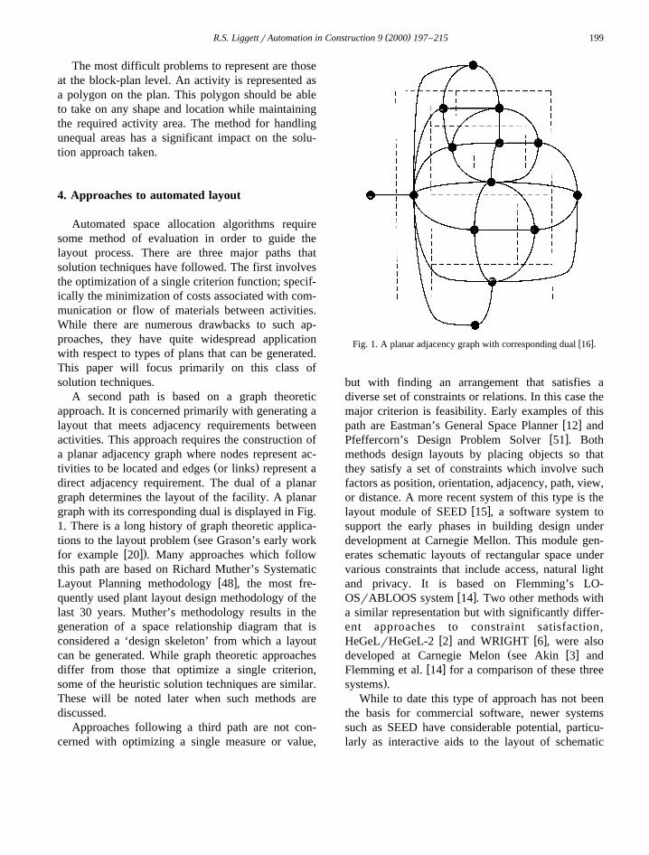
A second path is based on a graph theoreticapproach. It is concerned primarily with generating alayout that meets adjacency requirements betweenactivities. This approach requires the construction ofa planar adjacency graph where nodes represent ac-
Ž .tivities to be located and edges or links represent adirect adjacency requirement. The dual of a planargraph determines the layout of the facility. A planargraph with its corresponding dual is displayed in Fig.1. There is a long history of graph theoretic applica-
Žtions to the layout problem see Grason’s early workw x.for example 20 . Many approaches which follow
this path are based on Richard Muther’s Systematicw xLayout Planning methodology 48 , the most fre-
quently used plant layout design methodology of thelast 30 years. Muther’s methodology results in thegeneration of a space relationship diagram that isconsidered a ‘design skeleton’ from which a layoutcan be generated. While graph theoretic approachesdiffer from those that optimize a single criterion,some of the heuristic solution techniques are similar.These will be noted later when such methods arediscussed.
Approaches following a third path are not con-cerned with optimizing a single measure or value,
w xFig. 1. A planar adjacency graph with corresponding dual 16 .
but with finding an arrangement that satisfies adiverse set of constraints or relations. In this case themajor criterion is feasibility. Early examples of this
w xpath are Eastman’s General Space Planner 12 andw xPfeffercorn’s Design Problem Solver 51 . Both
methods design layouts by placing objects so thatthey satisfy a set of constraints which involve suchfactors as position, orientation, adjacency, path, view,or distance. A more recent system of this type is the
w xlayout module of SEED 15 , a software system tosupport the early phases in building design underdevelopment at Carnegie Mellon. This module gen-erates schematic layouts of rectangular space undervarious constraints that include access, natural lightand privacy. It is based on Flemming’s LO-
w xOSrABLOOS system 14 . Two other methods witha similar representation but with significantly differ-ent approaches to constraint satisfaction,
w x w xHeGeLrHeGeL-2 2 and WRIGHT 6 , were alsoŽ w xdeveloped at Carnegie Melon see Akin 3 and
w xFlemming et al. 14 for a comparison of these three.systems .
While to date this type of approach has not beenthe basis for commercial software, newer systemssuch as SEED have considerable potential, particu-larly as interactive aids to the layout of schematic
( )R.S. LiggettrAutomation in Construction 9 2000 197–215200
w xFig. 2. Display of access paths in a SEED layout 15 .
plans in the design development phase of new facili-ties. Some advantages of these systems are that theyconsider multiple criteria, maintain acceptable activ-ity shape, and can usually handle issues of circula-tion space. Sample output from SEED with accesspaths displayed is shown in Fig. 2. A disadvantageof such systems is that they have not yet demon-strated the ability to handle large scale problems thatare encountered in actual practice.
While a more detailed exploration of solutiontechniques for layout problems presented in the re-mainder of this paper focuses primarily on the first
Žclass of problems the optimization of a single crite-.rion function , solution methods of the other classes
of problems will also be discussed as they relate tothe overall classification framework.
5. One-to-one assignment: An early formulationas A Quadratic Assignment Problem
One of the most popular approaches to automatedfacility layout was first formulated by Koopmans
w xand Beckmann 34 for problems concerned with theassignment of manufacturing plants to sites such thatthe cost of transportation of the flow of goods be-tween plants is minimized. Known as the Quadratic
Ž .Assignment Problem QAP , it is concerned withfinding optimal locations for a set of interrelatedobjects. The problem can be described as follows.
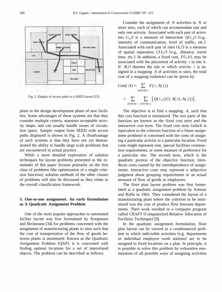
Consider the assignment of N activities to N ormore sites, each of which can accommodate one andonly one activity. Associated with each pair of activi-
Ž . Ž . Žties i, j is a measure of interaction Q i, j e.g.,.intensity of communication, level of traffic, etc. .
Ž .Associated with each pair of sites k,l is a measureŽ . Žof spatial separation C k,l e.g., distance, travel
. Ž .time, etc. . In addition, a fixed cost, F i,k , may beassociated with the placement of activity i in site k.
Ž .If A i denotes the site to which activity i is as-signed in a mapping A of activities to sites, the total
Ž .cost of a mapping solution can be given by:
Cost A s F i , A iŽ . Ž .Ž .Ýactivity i
q Q i , j C A i , A j .Ž . Ž . Ž .Ž .Ý Ýactivity i activity j
The objective is to find a mapping A, such thatthis cost function is minimized. The two parts of thefunction are known as the fixed cost term and the
Žinteractive cost term. The fixed cost term which isequivalent to the criterion function of a linear assign-
.ment problem is concerned with the costs of assign-ing a particular activity to a particular location. Fixedcosts might represent rent, special facilities construc-tion requirements, or some measure of preference fora particular site. The second term, which is thequadratic portion of the objective function, intro-duces costs caused by the interdependence of assign-ments. Interactive costs may represent a subjectivejudgment about grouping requirements or an actualmeasure of flow of goods or employees.
The floor plan layout problem was first formu-lated as a quadratic assignment problem by Armourand Buffa in 1963. They considered the layout of amanufacturing plant where the criterion to be mini-mized was the cost of product flow between depart-ments. Their work resulted in a computer program
Žcalled CRAFT Computerized Relative Allocation of. w xFacilities Technique 9 .
In the quadratic assignment formulation, floorplan layout can be viewed as a combinatorial prob-
Žlem in which indivisible activities e.g. departments.or individual employee work stations are to be
assigned to fixed locations on a plan. In principle, itis possible to solve this problem by exhaustive enu-meration of all possible ways of assigning activities
( )R.S. LiggettrAutomation in Construction 9 2000 197–215 201
to locations, and by selection of a plan which satis-Žfies given constraints andror as in the case of the
.quadratic assignment formulation yields the mini-mum value for the criterion function. In practice thisturns out to be infeasible for problems of realistic
Ž .size problems of over 15 activities since the num-ber of activityrlocation combinations involved is sovast.
It can be shown that quadratic assignment prob-lems belong to a class of mathematical problemsknown as NP-complete. It is generally accepted thatthe efficient solution of NP-complete problems isimpossible in principal. However a number of goodapproximate solution strategies do exist that producehigh quality solutions to realistically sized problemsat acceptable cost. This is particularly true for thespecial case of the one-to-one problem. As men-tioned previously, one-to-one formulations have anumber of commercial applications in terms of the
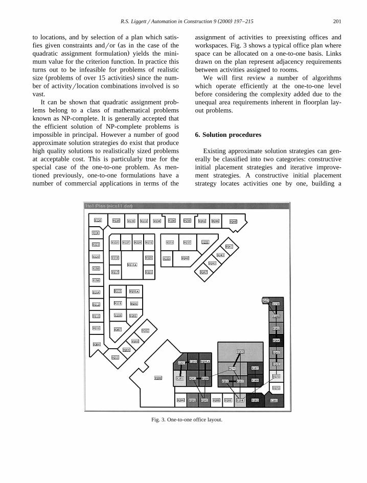
assignment of activities to preexisting offices andworkspaces. Fig. 3 shows a typical office plan wherespace can be allocated on a one-to-one basis. Linksdrawn on the plan represent adjacency requirementsbetween activities assigned to rooms.
We will first review a number of algorithmswhich operate efficiently at the one-to-one levelbefore considering the complexity added due to theunequal area requirements inherent in floorplan lay-out problems.
6. Solution procedures
Existing approximate solution strategies can gen-erally be classified into two categories: constructiveinitial placement strategies and iterative improve-ment strategies. A constructive initial placementstrategy locates activities one by one, building a
Fig. 3. One-to-one office layout.
( )R.S. LiggettrAutomation in Construction 9 2000 197–215202
solution from scratch in a step-by-step fashion. AnŽ .iterative improvement also known as hill climbing
strategy begins with some initial arrangement andattempts to improve it incrementally. Simulated an-nealing, can be viewed as a variant of an iterativeimprovement strategy. More recently, genetic algo-rithms have become of interest for the solution ofcombinatorial problems such as the QAP. Geneticalgorithms begin with a set of possible solutions anduse mutation and crossover techniques to evolveexisting solutions into better solutions. The nextsections will briefly cover basic improvement and
Ž w xconstructive techniques see Refs. 33,37–39 for amore detailed description and comparison of early
.techniques and then focus on newer approacheswhich include simulated annealing and genetic algo-rithms.
6.1. ConstructiÕe procedures
Constructive procedures build a solution fromscratch using an n-stage decision process. Somemethods attempt to automate a set of ‘rules ofthumb’ for making intelligent assignments at eachstage, essentially modelling the thought process of ahuman designer. A simple activity selection rulemight be: select the activity which has the highestconnectivity to any activity already placed. A loca-tion can then be selected, either by a simple rule of
Žthumb again e.g., select the first empty locationadjacent to a placed activity starting at the top left
.and working clockwise , or by more sophisticatedcriteria such as selecting that location which yieldsthe minimum value of the criterion function consid-
Žering only the activities already placed. See Refs.w x .11,42,49 for early constructive procedures .
The constructive decision process can be viewedas a ‘tree search’ where at each branch the selectionof an activity–location assignment is made. Twomore sophisticated and computationally intensive ap-proaches use mathematical bounds on the decisiontree to guide the process. At each stage of the
w x w xdecision tree, Gilmore 18 and Hillier 25 calculatea lower bound for the objective function for eachbranch. The activity–location pair which yields theminimum lower bound is selected for the next as-
w xsignment. Graves and Whinston 21 use probabilitytheory to calculate the expected value of the objec-tive function for each possible activity–location as-
signment at any step in the decision tree, and selectthe assignment which seems most likely to lead to anoptimal solution.
Constructive methods generally adopt either a‘local’ or ‘global’ orientation to a problem. Localmethods consider only the assignments which havealready been made; they tend to be less expensivebut yield poorer solutions. Global techniques attemptto account for possible future moves in the evalua-tion of a particular assignment and, although moreexpensive, generally produce better solutions. Boththe Gilmore–Hillier and Graves–Whinston algo-rithms are examples of global techniques.
6.2. ImproÕement procedures
Improvement procedures start with a single solu-tion and attempt to incrementally improve it. Thesimplest version is the ‘pair-wise’ exchange. Startingfrom an initial solution, the procedure consists ofsystematically evaluating possible exchanges be-tween pairs of activities and making an exchange ifit improves the value of the criterion. There are anumber of variants on the basic pair-wise exchangewhich focus on reducing the computational effortexpended or on improving the quality of the solu-tions generated. These variants generally involve themethod of selection of activities for possible ex-
Žchange and which exchange to make e.g., whetheror not to make the first exchange that leads to animprovement or to evaluate all possible exchangesand select the exchange that results in the maximum
.cost improvement . Since this latter method can bevery costly with respect to computation time, meth-ods use different ways to limit evaluation of ex-
w xchanges. For example, Elshafei 13 only evaluatesall possible moves of a single activity. Hanan et al.w x22 limit exchanges to immediate neighborhoods or
w xactivities. Volmann et al. 59 only considered theexchange of the two activities which contribute themost to the total cost of the current solution at eachstep. Other methods attempt to be intelligent aboutthe order in which they evaluate potential exchangesw x25,26 . A more expensive approach termed ‘biasedsampling’ selects randomly from the set of possibleexchanges showing improvement. The probability ofselection associated with each exchange is propor-
w xtional to its corresponding cost reduction 50 . Re-sults have also been reported for experiments involv-
( )R.S. LiggettrAutomation in Construction 9 2000 197–215 203
ing three-way, four-way and five-way exchangesw x7,42 , however, the minor improvements to solu-tions have generally not balanced the additional costof the generation process.
Improvement procedures usually converge on lo-cal optima. Since all improvement procedures re-quire an initial solution, a number of local optimacan be generated and compared by using different
w xstarting configurations. Elshafei 13 experimentedwith a technique to retreat from a local optimum byselecting the move which results in the minimumcost increase. The exchange cycle is then repeatedusing this position as the starting solution whichhopefully leads to a new local optima. A more recentsolution technique taken from the area of statisticalmechanics, simulated annealing, has been used to‘back out’ of unattractive local optima.
6.3. Simulated annealing
Simulated annealing techniques eliminate manyŽ .disadvantages of improvement hillclimbing meth-
ods. Solutions no longer depend on the starting pointŽand are more likely to converge on a good if not
.optimal solution. The main departure from tradi-tional improvement methods is that changes acceptedat each stage of the optimization can actually in-crease the cost of the plan. In most hillclimbingmethods, a new solution is accepted only if it yieldsan improved value of the objective function. Insimulated annealing, an exchange can also be ac-cepted if the probability of the resulting cost increaseoccurring is lower than a control parameter. Thistechnique is derived from a method that simulatesthe cooling of a mass of vibrating atoms from a high
Ž .temperature T. The probability of acceptance p ofthe exchange of a pair of activities equals one if theexchange provides a better value of the objectivefunction. If, however, the cost change is positiveŽ .i.e., increases the cost , the probability of accep-tance p is a function of the difference in values ofobjective function for the current solution and the
Ž .new solution D , and an additional control parame-Žter, T which represents temperature in the actual
. Ž Ž ..annealing process : ps exp yDrT . In general,the lower the temperature T is, the smaller thechances for the acceptance of a new solution are.During execution of the algorithm, the temperature
of the system, T , is lowered in steps. The algorithmterminates as T approaches zero. The use of simu-lated annealing techniques makes it less likely to fallinto local optima, provided the annealing process islong enough.
w xSharpe and Marksjo 53 show how an implemen-tation of the simulated annealing method provides arelatively simple but powerful approach to facilitylayout optimization. They have applied it success-fully to large scale problems with up to 200 loca-tions. An additional advantage is that it can producea number of near-optimal solutions from which de-signers can select. Similar advantages are shown bythe author of a program called CLASS, Computer-ized Layout Solutions using Simulated annealingw x30 .
6.4. Genetic algorithms
Somewhat related to improvement procedures area class of algorithms which rely on analogies tonatural processes. This type of algorithm has been
w xdescribed by Michalewicz 45 as follows:
Genetic algorithms are based on the principle ofŽ .evolution survival of the fittest . In such algo-
Žrithms a population of individuals potential solu-. Žtions undergoes a sequence of unary mutation. Ž .type and higher order crossover type transfor-
mations. As these individuals strive for survival: aselection scheme, biased towards fitter individu-als, selects the next generation. After some num-ber of generations, the algorithm converges withthe best individual hopefully representing the op-timum.
Genetic algorithms share the following featuresŽ w x.see Tate and Smith 56 :
ŽØ An initial population of solutions can be ran-.domly generated
Ø A mechanism for generating new solutions bycombining features from solutions in the existing
Ž .population reproduction .Ø A mechanism for generating a new solution by
operating on a single previously known solutionŽ .mutation .
Ø A mechanism for selecting the set of solutionsŽ .from the population s , giving preference to those
Ž .with better objective function values selectionand
( )R.S. LiggettrAutomation in Construction 9 2000 197–215204
Ø A mechanism for removing solutions from theŽ .population culling .
Solutions can be selected to mutate or to repro-duce. Selection is performed with a bias towardschoosing the better solutions in the current popula-tion. For the facilities layout problem mutation cantake the form of some variant of the pair-wise ex-change. The key feature of the reproduction process
w xused by Tate and Smith 56 is that any activityassigned the same location in both parents will oc-cupy that location in the offspring. For the remaininglocations, activity assignments are chosen randomlyfrom one or the other parent. Any unassigned activi-ties are then matched with the remaining unassignedlocations. As children are created, solutions with the
Ž .poorest values of the objective are eliminated culledto keep the population the same size. As for simu-lated annealing, excellent results have been reportedfor this type of algorithm and there is considerableinterest in investigating further extensions. Any ofthe reported improvement procedures are candidatesfor mutation processes and there are numerous possi-bilities for reproductive transformations.
w xGero and Kazakov 17 , extending earlier work byw xJo and Gero 29 , take advantage of what they term
‘superior’ evolved genes. Solutions, called geno-types, are represented as a linear sequence of inte-gers which can be interpreted as the order activitiesare placed on the plan. After a fixed number of
Žgenerations, the top ten percent of genotypes with.respect to a specified objective and the bottom ten
percent of genotypes are searched to identify groupsŽof genes that occur together compact subsets of
.activities that appear together in the sequence . Com-pact gene groups found almost exclusively in thebest solutions and almost never in the poorer solu-tions are declared new ‘superior’ evolved genes.These evolved genes are then represented as a singlegene for further reproduction. Applications of thisapproach show excellent results for an office and ahospital layout problem found in the literature. Theauthors have also shown that evolved genes tend torepresent design features that can be re-used later insimilar layout problems.
Genetic search methods climb many peaks inparallel making it more likely to settle on a global ornear-global solution than constructive or improve-ment procedures. Genetic algorithms are also attrac-
tive as the mutation and reproductive mechanismscan be visualized in terms of human design pro-cesses. We can conceive of a designer working witha set of possible solutions which evolve toward oneor more preferred solutions. As these solutions evolvethere may be portions of the design which are com-mon to the best solutions. These are preserved whendesign options are combined to generate new solu-tions.
It is logical from a human perspective to think ofthe solution process as a hybrid of a number ofapproaches. This is also true for automating thelayout process and there are a number of hybridsolution techniques.
6.5. Hybrid approaches
ŽSince both iterative improvement which includes.simulated annealing and genetic algorithms require
initial solutions, it is generally preferable to beginwith a reasonable solution rather than one which israndomly generated. On the other hand, while con-structive procedures can produce good solutions,there is almost always room for improvement. Usinga constructive procedure to generate an initial solu-tion should reduce the number of iterations of theimprovement procedure and improve the quality of
w xthe solution generated 38 . The coupling of a con-structive procedure with an improvement procedureprovides an effective combination of a global andlocal approach to a problem. The constructive proce-dure sets the general tone of the solution while theimprovement procedure refines the details.
The author has shown good results with a hybridapproach which combines the Graves–Whinstonconstructive procedure with a pair-wise exchange
w ximprovement algorithm 37 . More recently Huntleyw xand Brown 27 have combined a high-level genetic
algorithm with a simulated annealing algorithm. Jow x w xand Gero 29 improve upon Liggett’s 39 solution
to an office layout problem by using it as an initialpopulation for their genetic search algorithm, EDGEŽ .Evolutionary Design based on Genetic Evaluation .
w xHeragu and Alfa 24 show that a hybrid methodwhich uses a modified penalty algorithm to generatean initial solution which is then improved usingsimulated annealing produces superior results whencompared to a two or three-way exchange procedure
( )R.S. LiggettrAutomation in Construction 9 2000 197–215 205
w xor just to simulated annealing alone. Kaku et al. 31propose a hybrid heuristic that consists of three parts.In the first part, several partial assignments are gen-erated for use as starting points for a constructive
Žheuristic a breadth first search tree is used to enu-.merate a set of good partial assignments . In the
second part, these starting points are used to con-struct complete assignments. They experimented with
w x w xboth the Gilmore 18 and Graves–Whinston 21constructive approaches for completing the solution.Finally, attempts at improving the constructed solu-tions are made by the application of both pair-wiseand triple-exchange routines.
7. Unequal areas
Most of the approaches reviewed above can beused to generate acceptable solutions to the one-to-one assignment problem. However, space planningproblems are generally more complex than the clas-sical quadratic assignment formulation due to theimposition of activity area requirements. Since areasrequired by activities are not necessarily equal, it isnot always feasible to match activities and locationson a one-to-one basis. Note, this is not true if
Ž .location perimeters e.g., existing offices have beenpredefined since the assignment of activities to loca-tions can be limited by size constraints. Such con-straints are generally handled in the quadratic assign-ment formulation with the fixed cost function. Fixedcosts can be set prohibitively high for the assignmentof activities to offices of unacceptable size. At theblock plan level, however, the problem becomesmore difficult since we are locating activities on aplan where location boundaries have not been pre-fixed.
7.1. Modular approach
A typical approach to the unequal area block planŽ .problem for the class of algorithms discussed above
is to partition the plan into equal size modules. Eachactivity is then partitioned into modules of the samesize according to required floor area. The problem isthen one of assigning activity modules to locationmodules in a one-to-one fashion. For the quadratic
Žassignment problem, artificially high interaction ad-
.jacency values can be specified between modules ofthe same activity to encourage contiguity of activityspace. Heuristics in constructive procedures can alsobe used to ensure contiguity of space. For example,after the initial module is placed for an activity in theLiggett implementation of the Graves–Whinston al-
w xgorithm 41 , locations evaluated for the placementof subsequent modules of the same activity are lim-ited to adjacent modules. The order of location mod-ule selection is based on the expected value of theobjective function. For constructive procedures thereis no guarantee, however, that activities will not be
Žsplit unless backtrack strategies are employed at.perhaps a prohibitive cost and modularization can
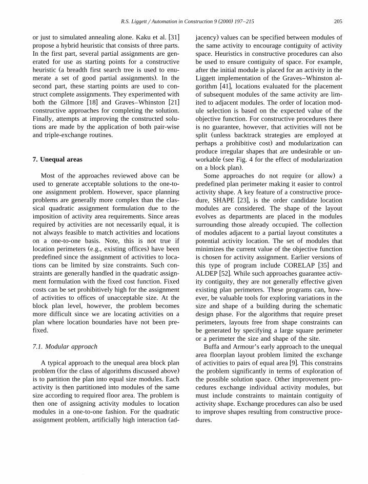
produce irregular shapes that are undesirable or un-Žworkable see Fig. 4 for the effect of modularization
.on a block plan .Ž .Some approaches do not require or allow a
predefined plan perimeter making it easier to controlactivity shape. A key feature of a constructive proce-
w xdure, SHAPE 23 , is the order candidate locationmodules are considered. The shape of the layoutevolves as departments are placed in the modulessurrounding those already occupied. The collectionof modules adjacent to a partial layout constitutes apotential activity location. The set of modules thatminimizes the current value of the objective functionis chosen for activity assignment. Earlier versions of
w xthis type of program include CORELAP 35 andw xALDEP 52 . While such approaches guarantee activ-
ity contiguity, they are not generally effective givenexisting plan perimeters. These programs can, how-ever, be valuable tools for exploring variations in thesize and shape of a building during the schematicdesign phase. For the algorithms that require presetperimeters, layouts free from shape constraints canbe generated by specifying a large square perimeteror a perimeter the size and shape of the site.
Buffa and Armour’s early approach to the unequalarea floorplan layout problem limited the exchange
w xof activities to pairs of equal area 9 . This constrainsthe problem significantly in terms of exploration ofthe possible solution space. Other improvement pro-cedures exchange individual activity modules, butmust include constraints to maintain contiguity ofactivity shape. Exchange procedures can also be usedto improve shapes resulting from constructive proce-dures.
( )R.S. LiggettrAutomation in Construction 9 2000 197–215206
Fig. 4. Effect of modularization on a block plan.
The method of plan modularization has importantimplications for the automated algorithm. If an exist-ing building has not been designed on a squareplanning grid or if the perimeter has other than rightangled edges, the modularized plan will only approx-imate the actual perimeter. The smaller the grid size,the better the approximation of the existing plan.However, a small grid size increases the number ofmodules. This leads to increased computation time ingenerating a layout. It may also cause fragmentedactivity shapes.
7.2. Arrangement of rectangles
Other approaches to the unequal area layout prob-lem partition rectangular shapes into smaller rectan-
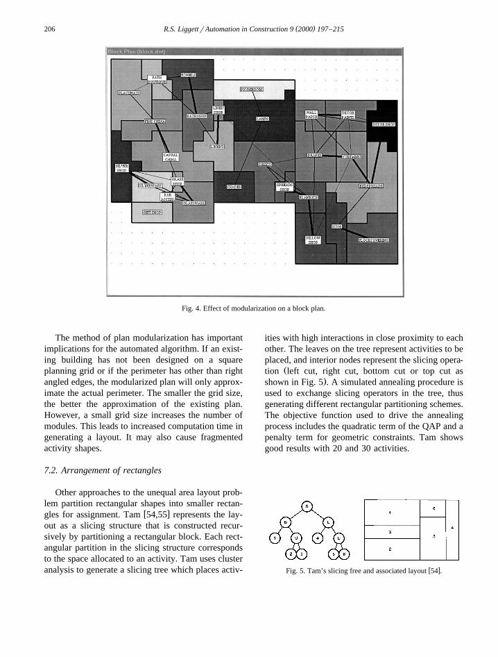
w xgles for assignment. Tam 54,55 represents the lay-out as a slicing structure that is constructed recur-sively by partitioning a rectangular block. Each rect-angular partition in the slicing structure correspondsto the space allocated to an activity. Tam uses clusteranalysis to generate a slicing tree which places activ-
ities with high interactions in close proximity to eachother. The leaves on the tree represent activities to beplaced, and interior nodes represent the slicing opera-
Žtion left cut, right cut, bottom cut or top cut as.shown in Fig. 5 . A simulated annealing procedure is
used to exchange slicing operators in the tree, thusgenerating different rectangular partitioning schemes.The objective function used to drive the annealingprocess includes the quadratic term of the QAP and apenalty term for geometric constraints. Tam showsgood results with 20 and 30 activities.
w xFig. 5. Tam’s slicing free and associated layout 54 .
( )R.S. LiggettrAutomation in Construction 9 2000 197–215 207
w xTate and Smith 57 use a genetic algorithm witha flexible bay structure. The prespecified rectangulararea is divided in one direction into bays of varyingwidth. Each bay is then divided into rectangularpartitions of equal width but different lengths. Thebays are flexible in that their widths will vary withtheir number and contents. In the Tate and Smith
w xequal-area genetic algorithm discussed earlier 56 , asolution was represented by a permutation of inte-
Žgers one through n, where n is the number of.activities and the locations of the integers in the
sequence correspond to locations on the plan. In thisimplementation, the locations correspond to bay par-titions and an additional sequence is required torepresent a solution. This second sequence definesthe number of bays and the number of partitions perbay by indicating where breakpoints exist. Changingthe location of break points can change the numberof rectangles per bay andror the number of bays.Solutions are evaluated and compared using the ob-jective function of the quadratic assignment problemwith the addition of adaptive penalty functions tohandle area and proportion requirements for activi-ties.
w xVan Camp et al. 58 use a nonlinear model.Activities are considered to be of fixed area but ofvariable dimensioned rectangular shape. Using a sim-ilar measure as the QAP, the objective functionrepresents the cost of flow of material between activ-ities multiplied by the distance between activity cen-troids. An additional term measures distance betweenactivities and the outside wall. Constraints requirethat no two departments overlap, that departmentsmust be contained in the facility and meet area as
Žwell as shape constraints again using the penalty.function approach . Nonlinear optimization is used to
Žgenerate an initial feasible solution note activitycentroids and dimensions are viewed as continuousvariables which can vary over the dimensions of the
.exterior boundaries . The nonlinear optimizationgenerally results in local optima. The procedure thenapplies a pair-wise exchange improvement procedureto reduce the value of the interactive portion of theobjective function. At this stage infeasible solutionsŽwhere an activity is too large for the available
.location are accepted. A return is then made to thenonlinear algorithm to generate a new feasible solu-tion.
8. Constraint based methods for unequal arealayout
Methods which do not focus on a single objectivebut rather seek to generate solutions that meet a
Ž .number of different possibly conflicting constraintsgenerally deal with the unequal area layout problemin terms of arrangements of rectangles. Three meth-
w x w xods mentioned earlier, LOOS 14 , WRIGHT 6 andw xHeGeL 2 , all formulate the problem as one of
arrangement of rectangles with sides parallel to axesof an orthogonal system. They all attempt to satisfytwo types of constraints: one set that is dependent onthe structure or topology of the problem such as therequirement that the rectangles not overlap and fitwithin a given boundary; and a second set of con-straints which are independent of structure and con-sider attributes such as area, dimension, orientation,and adjacency requirements.
LOOS and HelGeL are hierarchical generate-and-test methods that incrementally construct solutionsby adding one rectangle at a time to a partial solu-tion, testing for constraint satisfaction at each step.
w xLOOS 14 employs a breadth first search, generatingcandidate solutions at each stage by enumerating allpossible ways of adding a new rectangle to a partialsolution. Each intermediate state is examined forconstraint violation. If a structure dependent con-straint is violated the intermediate solution is pruned.A count of other constraints violated is made for anypartial state and only those with the lowest countsare selected for expansion. By sequentially expand-ing partial solutions and pruning less promising can-didates, LOOS commits to a set of current globallybest candidate solutions and avoids backtracking.
w xHeGeLrHeGeL2 2 also constructs a solution ina step-by-step fashion, however, it follows a depth-first search. The solution procedure is based on aprotocol analysis of the problem-structuring andproblem solving behavior of designers. Layout re-quirements are expressed as relationships betweenobjects to be located. These relationships, which arecalled ‘predicates’, are used as generative constraintsor evaluative criteria. A generative predicate results
Žin the selection of a design unit to be placed for.example, a direct access requirement . Alternative
locations for the design unit are then generated basedon the predicate. These locations are tested against
( )R.S. LiggettrAutomation in Construction 9 2000 197–215208
the other predicates associated with the design unit.If none of the generated locations meets the testcriteria, HeGeL will backtrack. If a single locationmeets the criteria, the placement is made. If there aremultiple locations, they are presented to the user forselection. The user selects a final location and othersare stored for possible later backtracking. While theoriginal approach relied on the user to direct thesearch in terms of selection of the next generativepredicate or unit to place, HeGeL2 implements anoptimization methodology to make the best place-ment decision at each stage.
w xWRIGHT 6 implements a constraint-directedsearch called disjunctive constraint satisfaction inwhich constraints are incrementally satisfied. Thelayout is represented using algebraic equations andinequalities of variables that represent the borderlines, dimensions, areas and orientation of the designunits. These are called atomic constraints. Disjunc-tive constraints are Boolean combinations of atomicconstraints and specify the ‘‘structural alternativesconsidered by WRIGHT for satisfying theconstraint.’’ For example, a disjunctive constraintmight represent the four alternatives of placing one
Žunit directly adjacent to another it can be north,.south, east or west of the second . Solutions are
generated by sequentially instantiating disjunctiveconstraints and solving the current constraint satis-
Ž .faction problem CSP . A CSP is consistent if thereexists values for all variables that simultaneouslysatisfy all constraints. If a CSP is inconsistent, thepropagation algorithm backtracks and selects an al-ternative disjunct. The full solution process will findall significantly different solutions. Since a problemcan be underconstrained or overconstrained, the de-sign process is characterized by the addition or relax-ation of constraints by the designer.
Rather than formulating competing criteria as aw xdiverse set of constraints, Jacobs 28 combines them
into a single weighted objective function. The crite-ria considered include the distance between design
Žunits with respect to frequency of interaction thetypical single objective function criteria considered
.by the first class of solution techniques , as well asdirect adjacency requirements. He also includes cri-teria related to the alignment of spaces with a goal ofkeeping the structure of the layout as simple aspossible. A final consideration is the use of space.
Designers can choose between minimizing emptyŽ .space making the most use of space or maximizing
empty space by compacting the layout. Jacobs uses atwo-stage solution procedure where each stage com-bines both a constructive and improvement proce-dure. In the first stage units are ranked for order ofplacement by boundary preferences, adjacency pref-erences, and the distance measure. A solution is thenconstructed incrementally based on the priority or-dering by generating all feasible locations for thenext design unit to be placed. A location is selectedfor placement based on the objective function. If aunit will not fit on the layout, all units are removedand the process is restarted. Once a solution isconstructed it is improved with a pair-wise exchangeprocedure. Since there is an element of randomnessin the initial placement ordering as well as in the
Žselection of a location for placement if two loca-tions yield the same value for the objective, the
.selection is made randomly , a different solution willresult each time the process is restarted.
9. Graph theoretic approaches
Graph theoretic approaches also handle the un-equal area block plan. In these approaches a blockplan is constructed as the dual of a planar graphwhere nodes represent spaces and links representrequired adjacencies. While it is always possible toconstruct a block plan from a planar graph whichmeets the given adjacency requirements betweenspaces and between spaces and the outside area, theresulting plan may not meet size and shape require-ments imposed on each space. Constructing a blockplan that meets size and shape requirements is anontrivial problem.
A graph theoretic approach is a two stage process.In the first stage a planar graph which corresponds tothe adjacency requirements is generated. A planargraph is one which can be drawn so that no twoedges intersect. A planar graph is maximal if noedges can be added without losing planarity. It ispossible that the adjacency requirements cannot berepresented by a planar graph. In this case the prob-lem is overconstrained and the solution procedurebecomes one of generating maximal planar graphs
( )R.S. LiggettrAutomation in Construction 9 2000 197–215 209
which maximize the number of adjacencies or theweighted adjacencies met by the graph. Once a graphhas been formed, the second stage involves generat-
w xing the actual layout. See Baybars and Eastman 5w xand Foulds 16 for a more detailed discussion of the
graph theoretic approach and early applications.A typical graph theoretic heuristic for the layout
problem consists of the following steps:Stage 1: Generating a planar graphØ Form a weighted graph of the relationships
between facilitiesØ Identify a maximal planar subgraph of rela-
tively high weightStage 2: Generating a block planØ Construct the dual from the planar subgraph.
The dual represents a layout apart from the factthat shapes and areas have not been taken intoaccount.
Ø Attempt to accommodate shapes and areas informing a block plan from the dual.
Much research focuses on just the first stage ofthe process-generating a maximal planar graph. Aplanar graph can be generated by adding or subtract-ing edges following a step-by-step process. Typically
Žedges are added in a greedy fashion local construc-.tive method where planarity is tested after each
w xedge addition. Leung 36 presents such a construc-tive procedure which capitalizes on the fact thattriangulated graphs are maximally planar. Themethod starts with a planar subgraph which is gener-ated by enumerating all possible groups of fourvertices. The group with maximum weight is se-lected. At each subsequent step either a single vertexor a triple of vertices which maximizes the additionaledge-weight per vertex is added to a face. Once amaximal planar graph is constructed, many methodsapply some type of improvement procedure such aspair-wise exchange or simulated annealing to im-prove the adjacency score while maintaining pla-narity.
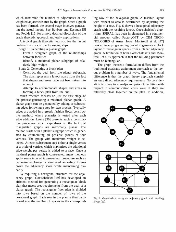
By requiring a hexagonal structure for the adja-w xcency graph, Goetschalckx 19 has developed an
efficient method for generating a rectangular blockplan that meets area requirements from the dual of aplanar graph. The rectangular floor plan is dividedinto rows based on the number of rows of thehexagonal graph. Each row in the plan is then parti-tioned into the number of spaces in the correspond-
ing row of the hexagonal graph. A feasible layoutwith respect to area is determined by adjusting theheight of a row. Fig. 6 shows a hexagonal adjacencygraph with the resulting layout. Goetschalckx’s algo-rithm, SPIRAL, has been implemented in a commer-cial product called FactoryOPT by CIM TECH-
w xNOLOGIES of Ames, Iowa. Montreuil et al. 47uses a linear programming model to generate a blocklayout of rectangular spaces from a planar adjacencygraph. A limitation of both Goetschalckx’s and Mon-treuil et al.’s approach is that the building perimetermust be rectangular.
The graph theoretic formulation differs from thetraditional quadratic assignment approach to the lay-out problem in a number of ways. The fundamentaldifference is that the graph theory approach consid-ers only direct adjacency requirements. No consider-ation is given to nonadjacent pairs of facilities withrespect to communication costs, even if they arerelatively close together on the plan. In addition,
Fig. 6. Goetschkhs’s hexagonal adjacency graph with resultingw xlayout 19 .
( )R.S. LiggettrAutomation in Construction 9 2000 197–215210
fixed costs are not included in the graph theoreticformulation nor are preassigned spaces accommo-
w xdated. Foulds 16 views the graph theoretic ap-proach as more appropriate for the design of a newfacility where there is more design freedom, whilethe QAP formulation is more useful in a structuredsituation.
10. Many-to-one and one-to-many assignment
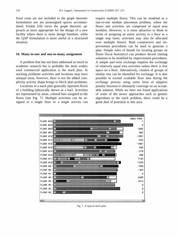
A problem that has not been addressed as much inacademic research but is probably the most widelyused commercial application is the stack plan. Instacking problems activities and locations may haveunequal areas, however, there is not the added com-plexity activity shape brings to block plan problems.
Locations in a stack plan generally represent floorsŽ .of a building physically shown as a bar . Activities
are represented by areas, colored bars assigned to theŽ .floors see Fig. 7 . Multiple activities can be as-
signed to a single floor or a single activity can
require multiple floors. This can be modeled as aone-to-one module placement problem, where thefloors and activities are comprised of equal areamodules. However, it is more attractive to think interms of assigning an entire activity to a floor in a
Žsingle step note, activities may also be allocated.over multiple floors . Both constructive and im-
provement procedures can be used to generate aplan. Simple rules of thumb for locating groups on
Ž .floors local heuristics can produce decent startingsolutions to be modified by improvement procedures.A simple pair-wise exchange requires the exchangeof relatively equal area activities unless there is freespace on a floor. Alternatively, clusters of groups ofsimilar size can be identified for exchange. It is alsopossible to exceed available floor area during theexchange process using some form of adaptivepenalty function to ultimately converge on an accept-able solution. While we have not found applicationsof some of the newer approaches such as geneticalgorithms to the stack problem, there could be agreat deal of potential in this area.
Fig. 7. A typical stack plan.
( )R.S. LiggettrAutomation in Construction 9 2000 197–215 211
w xMahdavi et al. 43 , Zhang presents a new ap-proach to the stacking problem. She clusters what are
Ž .termed functional units activities to be located intogroups and assigns groups to floors such that theweight between floors is minimized. To begin theprocess functional units are sorted by their totalconnected weights in descending order. Each of thefirst nfy1 units is then assigned to a separate groupŽwhere nf represents the number of floors in the
.stacking problem . The remaining units are assignedto the last group. Each group has an area constraintcorresponding to one floor of the building. Func-tional units are moved from the last group to othergroups such that intergroup weights are minimizedand area requirements are satisfied. When no movewill produce a gain or improve the area balance, theprocess is over. Groups are now assigned to actualfloors. If the floors are of different size than it isobvious which cluster is assigned to which floor. Ifthey are the same size, a dynamic programmingalgorithm is used to assign groups to floors with theobjective of maximizing adjacent floor weights.
Another similar problem is the assignment ofmultiple occupants to a single office. In this case aswell, an algorithm need not worry about the actualshape of space, only the activity area assigned toeach location. The same solution techniques can beapplied to the stack and the many-to-one officeassignment problem. Only the graphic representationis different.
11. Multi-floor layout problems
Block and stack problems are considered simulta-w xneously with multi-floor algorithms. Bozer et al. 8
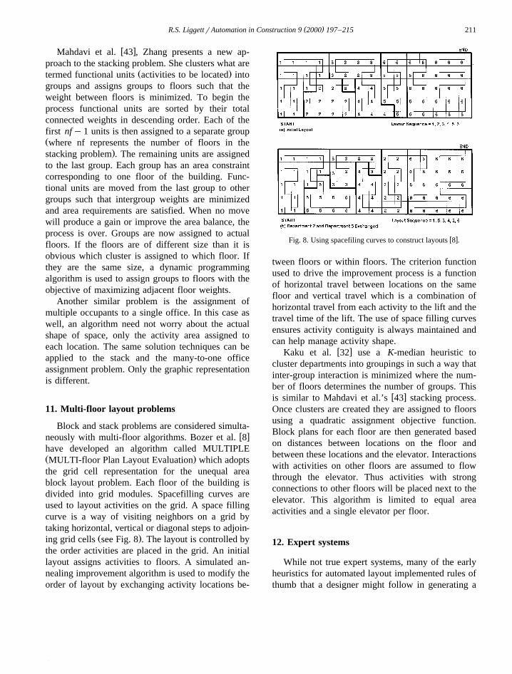
have developed an algorithm called MULTIPLEŽ .MULTI-floor Plan Layout Evaluation which adoptsthe grid cell representation for the unequal areablock layout problem. Each floor of the building isdivided into grid modules. Spacefilling curves areused to layout activities on the grid. A space fillingcurve is a way of visiting neighbors on a grid bytaking horizontal, vertical or diagonal steps to adjoin-
Ž .ing grid cells see Fig. 8 . The layout is controlled bythe order activities are placed in the grid. An initiallayout assigns activities to floors. A simulated an-nealing improvement algorithm is used to modify theorder of layout by exchanging activity locations be-
w xFig. 8. Using spacefiling curves to construct layouts 8 .
tween floors or within floors. The criterion functionused to drive the improvement process is a functionof horizontal travel between locations on the samefloor and vertical travel which is a combination ofhorizontal travel from each activity to the lift and thetravel time of the lift. The use of space filling curvesensures activity contiguity is always maintained andcan help manage activity shape.
w xKaku et al. 32 use a K-median heuristic tocluster departments into groupings in such a way thatinter-group interaction is minimized where the num-ber of floors determines the number of groups. This
w xis similar to Mahdavi et al.’s 43 stacking process.Once clusters are created they are assigned to floorsusing a quadratic assignment objective function.Block plans for each floor are then generated basedon distances between locations on the floor andbetween these locations and the elevator. Interactionswith activities on other floors are assumed to flowthrough the elevator. Thus activities with strongconnections to other floors will be placed next to theelevator. This algorithm is limited to equal areaactivities and a single elevator per floor.
12. Expert systems
While not true expert systems, many of the earlyheuristics for automated layout implemented rules ofthumb that a designer might follow in generating a
( )R.S. LiggettrAutomation in Construction 9 2000 197–215212
layout. Modelling the solution process of the humandesigner is dealt with more explicitly in the work by
w xAkin et al. 2 on layout protocol analysis whichresulted in the HeGeL system discussed earlier.
A more traditional expert system approach devel-w xoped by Malakooti and Tsurushima 44 combines
multiple-criteria decision making with an expert sys-tem. The expert system has four parts:Ø A data base which expresses the problem to be
solved. All raw data is treated as facts such as thenumber of activities, size, and flow.
Ø A knowledge base which stores domain-specificproblem-solving knowledge such as rules ofthumb for generating the layout.
Ø A priority base, which contains priorities for rules,adjacency, the order of assignment, etc.
Ø An inference engine, which controls theproblem-solving structure.The expert system interacts with the decision
maker through the inference engine allowing thedecision maker to change the priorities or rules. Aninterpretation of the layout, which includes all therules that have been used to assign activities to sites,is displayed so that the decision maker can see whyindividual assignments have been made. A what-ifanalysis module allows the decision maker to changeinformation in the data, the knowledge or prioritybases and see the results. By giving priority todifferent criteria and comparing the resulting layouts,the system can automatically update priorities basedon the decision maker’s choices.
Recent references to expert systems tend to focusmore on the integrated problem solving experiencethan on the actual layout process. Many expert sys-tems use existing tools for the actual layout whichinclude both constructive and improvement proce-
w xdures mentioned earlier. Abdou and Dutta 1 use anexpert system to derive the relationship chart from aset of multiple criteria that are fuzzy, non-quantifia-ble and apparently conflicting. Once the relationshipsare derived a standard layout generation packageŽ .such as ALDEP or CORELAP is used to derive asuitable layout. The expert system is then used toexamine the feasibility of the result.
w xFLEXPERT 4 , a facility layout expert systembased on the theory of fuzzy logic follows a similarscenario. It uses the expert system to generate arelationship chart to combine criteria on flow and
closeness relationships between departments. A stan-dard constructive algorithm is linked with an im-provement component to generate the layout. Cle-
w xland and Hills 10 use a simulated annealing ap-proach for the actual layout, but use a knowledge-based system as an intelligent editor to guide thedesigner in problem formulation and as an intelligentcritic to assess the quality of the layout and tosuggest ways to improve it.
13. Commercial applications
While there seems to be considerable interest incomputer programs for facility layout, there are sur-prisingly few commercially available products. Theso-called ‘layout’ features of many CAD systemssimply provide a graphic interface for the user tolayout a plan in manual mode with little or no accessto information concerning the layout criteria. On theother hand, a solution generated by an automatedalgorithm that is based on a single cost functioncaptures only one aspect of a designer’s concerns inany realistic context. A system which meets com-mercial needs of today should provide interface ca-pabilities ranging from complete user interaction,where the user interactively specifies the location ofeach activity, to complete automation, where an
w xalgorithm generates an initial solution 40 . Or asdesired, a designer should be able to interactivelylocate some activities and use an algorithm to locateor suggest locations for others. Rather than generat-ing a single least-costly plan, the designer with theaid of automated algorithms can make tradeoffs be-tween competing criteria and converge on a solutionthat responds to a broad spectrum of complex andoften ill-defined issues.
In order to meet the needs of facility designersand managers a number of factors must be present ina commercial product:Ø The ability to handle large scale problemsØ A modern interactive interfaceØ Support for an iterative design processØ Links to CAD and Facilities Management
DatabasesIt is clear that realistic space allocation problems
can involve the assignment of space for very largeorganizations. A single problem can include multiple
( )R.S. LiggettrAutomation in Construction 9 2000 197–215 213
buildings, numerous floors and hundreds if not thou-sands of activities. Automated solution procedures todate have not been tested for problems of this size.
The program interface should be able to prepareand present data at any desired level of aggregationand use output from one stage of the design process
Žto generate subproblems at the next stage for exam-ple, from stacking a multi-storey building to block
.plans of individual floors . An early commercialimplementation, the Calcomp Facilities Planning andManagement Application Package, allowed designersto select both the level of space aggregation andactivity aggregation from a graphically displayedorganization chart. Such an approach is an effectiveway of reducing the size of large scale problems tomake both human and algorithmic problem solvingpossible. Newer drag and drop graphic interfaces,now expected by users, can be used to move activi-ties from an organization chart to the graphic repre-sentation of a plan or to shift activities around a plan.
Experience has shown that layout tools are mosteffective when employed in an iterative fashion. Forexample, in a typical layout problem, the designprocess might start by automatically generating aplan where only information on activity interactionsis considered. Generally the result produced will beunsatisfactory, prompting the designer andror clientto make their design requirements more explicit.This can be accomplished by adding information onactivity–location preferences and activity preassign-ments. Location preferences, for example, can beadded to the quadratic assignment objective functionin the form of fixed costs. Most systems should alsohave the capability for preassigning activities to par-ticular locations to account for preexisting condi-tions. Appropriate trade-offs can then be made as theproblem is gradually transformed from one in whichfew locations are fixed to a complete solution.
One of the most important applications of com-puterized facility layout is in the area of ongoingspace management. Here the link between a facilitiesmanagement database and the layout program iscritical. An inventory database of personnel, equip-ment and space provides information on the currentlayout of space in the building which can be dis-played and evaluated by the layout program. Thelayout program can then be used to generate and testalternative configurations meeting new space re-
quirements. Output resulting from a layout plannercan be used to update the databases and even gener-ate transactions such as move orders.
In spite of the long research history associatedwith automated layout and space allocation systems,in practice these systems have not been utilized totheir full potential. We would expect this to changein the near future given the increasing interest infacilities planning and management, the increasinguse of computer-aided design tools in the buildingdesign and management industry, and the improve-ments in computer hardware and software whichmake the solution of larger scale problems possibleas well as facilitate human–computer interaction.
References
w x1 G. Abdou, S. Dutta, An integrated approach to facilitiesŽ . Ž .layout using expert systems, Int. J. Prod. Res. 28 4 1990
685–708.w x2 O. Akin, B. Dave, S. Pithavadian, Heuristic generation of
Ž .layouts HeGeL : based on a paradigm for problem structur-Ž .ing, Environ. Plan. B: Plan. Des. 19 1992 33–59.
w x3 O. Akin, R. Sen, Navigation within a structure search spaceŽ .in layout problems, Environ. Plan. B: Plan. Des. 23 1996
421–442.w x4 A. Badiru, A. Arif, FLEXPERT: facility layout expert system
Ž .using fuzzy linguistic relationship codes, IIE Trans. 28 4Ž .1996 295–309.
w x5 I. Baybars, C. Eastman, Enumerating architectural arrange-ments by generating their underlying graphs, Environ. Plan.
Ž .B 7 1980 289–310.w x6 C. Baykan, Formulating spatial layout as a disjunctive con-
straint satisfaction problem, Doctoral Dissertation, Depart-ment of Architecture, Carnegie Mellon University, 1991.
w x7 T. Block, PLOP—Plant layout optimization procedure, Uni-versity of Melbourne, Melbourne, 1978.
w x8 Y. Bozer, R. Meller, S. Erelebacher, An improvement-typelayout algorithm for single and multiple-floor facilities, Man-
Ž . Ž .age. Sci. 40 7 1994 918–932.w x9 E. Buffa, G. Armour, Allocating facilities with CRAFT,
Ž . Ž .Harvard Business Rev. 42 2 1964 136–159.w x10 G. Cleland, W. Hills, A knowledge-based systems approach
to the layout design of large made-to-order products, in: J.S.Ž .Gero, F. Sudweeks Eds. , Artificial Intelligence in Design
’94, Kluwer, The Netherlands, 1994, pp. 257–274.w x11 H. Edwards, B. Gillett, M. Hale, Modular allocation tech-
Ž . Ž . Ž .nique MAT , Management Sci. 17 3 1970 161–169.w x12 C. Eastman, Automated space planning, Artificial Intelli-
Ž .gence 4 1973 41–64.w x13 A. Elshafei, Hospital layout as a quadratic assignment prob-
Ž . Ž .lem, Operations Res. Q. 28 1 1977 167–179.w x14 U. Flemming, C. Baykan, R. Coyne, Hierarchical generate-
( )R.S. LiggettrAutomation in Construction 9 2000 197–215214
Ž .and-test versus constraint-directed search, in: J. Gero Ed. ,Proceedings of the Artificial Intelligence in Design Confer-ence ’92, Kluwer, Dordrecht, 1992, pp. 817–838.
w x15 U. Flemming, R. Coyne, S. Fenves, J. Garrett, R. Woodbury,SEED—software environment to support the early phases inbuilding design, Proc. IKM94, Weimar, Germany, 1994, pp.5–10.
w x16 L. Foulds, Techniques for facilities layout: deciding whichpairs of activities should be adjacent, Management Sci. 29Ž . Ž .12 1983 1414–1426.
w x17 J. Gero, V. Kazakov, Space layout problems using evolvedŽ . Ž .design genes, Artificial Intelligence in Eng. 12 3 1998
163–176.w x18 P. Gilmore, Optimal and suboptimal algorithms for the
quadratic assignment problem, J. Soc. Ind. Appl. Math. 10Ž . Ž .2 1962 305–313.
w x19 M. Goetschalckx, An interactive layout heuristic based onhexagonal adjacency graphs, Eur. J. Operational Res. 63Ž .1992 304–321.
w x20 J. Grason, An approach to computerized space planningusing graph theory, Proceedings of the Design AutomationWorkshop, June 28–30, Atlantis City, NJ, IEEE, New York,1971, pp. 170–179.
w x21 G. Graves, A. Whinston, An algorithm for the quadraticŽ . Ž .assignment problem, Manage. Sci. 17 3 1970 453–471.
w x22 M. Hanan, P. Wolff, B. Agule, Some experimental results onplacement techniques, ACM Des. Automation Conf. Proc. 13Ž .1976 214–224.
w x23 M. Hassan, G. Hogg, D. Smith, SHAPE: a constructionalgorithm for area placement evaluation, Int. J. Prod. Res. 24Ž . Ž .5 1986 1283–1295.
w x24 S. Heragu, A. Alfa, Experimental analysis of simulated an-nealing based algorithms for the layout problem, Eur. J.
Ž .Operational Res. 57 1992 190–202.w x25 F. Hillier, Quantitative tools for plan layout analysis, J. Ind.
Ž . Ž .Eng. 14 1 1963 33–40.w x26 F. Hillier, M. Conners, Quadratic assignment problem algo-
rithms and location of indivisible facilities, Manage. Sci. 13Ž . Ž .1 1966 42–57.
w x27 C. Huntley, D. Brown, A parallel heuristic for quadraticŽ . Ž .assignment problems, Computers Ops. Res. 18 3 1991
275–289.w x28 F. Jacobs, A layout planning system with multiple criteria
Ž .and a variable domain representation, Manage. Sci. 33 8Ž .1987 1020–1034.
w x29 J. Jo, J. Gero, Space layout planning using an evolutionaryŽ . Ž .approach, Architectural Sci. Rev. 36 1 1995 37–46.
w x30 S. Jojodia, I. Minis, G. Harhalakis, J. Proth, CLASS: Com-puterized Layout Solutions using Simulated annealing, Int. J.
Ž . Ž .Prod. Res. 30 1 1992 95–108.w x31 B. Kaku, G. Thompson, T. Morton, A hybrid heuristic for the
Ž . Ž .facilities layout problem, Computers Ops. Res. 18 3 1991241–253.
w x32 B. Kaku, G. Thompson, I. Baybars, A heuristic method forthe multi-story layout problem, Eur. J. Operational Res. 37Ž .1988 384–397.
w x33 A. Kusiak, S. Heragu, The facility layout problem, Eur. J.Ž .Operational Res. 29 1987 229–251.
w x34 J. Koopmans, M. Beckmann, Assignment problems and loca-Ž .tion of economic activities, Econometrica 25 1967 53–76.
w x35 R. Lee, J. Moore, CORELAP—computerized relationshipŽ . Ž .layout planning, J. Ind. Eng. 18 3 1976 195–200.
w x36 J. Leung, A new graph-theoretic heuristic for facility layout,Ž . Ž .Manage. Sci. 38 4 1992 594–605.
w x37 R. Liggett, The quadratic assignment problem: an analysis ofŽ .applications and solution strategies, Environ. Plan. B 7 1980
141–162.w x38 R. Liggett, The quadratic assignment problem: an experimen-
Ž .tal evaluation of solution strategies, Manage. Sci. 27 1981442–460.
w x39 R. Liggett, Optimal spatial arrangement as a quadratic as-Ž .signment problem, in: J. Gero Ed. , Design Optimization,
Academic Press, 1985, pp. 1–40.w x40 R. Liggett, A designer-automated algorithm partnership, an
interactive graphic approach to facility layout, in: Y. KalayŽ .Ed. , Evaluating and Predicting Design Performance, Wiley,1992, pp. 101–124.
w x41 R. Liggett, W. Mitchell, Optimal space planning in practice,Ž . Ž .Computer-Aided Des. 13 5 1981 277–288.
w x42 M. Los, The Koopmans–Beckmann problem: some computa-tional results, Universite de Montreal, Centre de Recherchesur les Transports, 1976.
w x43 A. Mahdavi, O. Akin, Y. Zhang, Formularization of concur-rent performance requirements in building problem composi-tion, Working Paper, School of Architecture, Carnegie Mel-lon University, 1998.
w x44 B. Malakooti, A. Tsurushima, An expert system using priori-ties for solving multiple-criteria facility layout problems, Int.
Ž . Ž .J. Prod. Res. 27 5 1989 793–808.w x45 Z. Michalewicz, Genetic AlgorithmsqData Structuress
Evolution Programs, Springer-Verlag, Berlin, 1992.w x46 B. Montreuil, A. Laforge, Dynamic layout design given a
scenario tree of probable futures, Eur. J. Operational Res. 63Ž .1992 271–286.
w x47 B. Montreuil, U. Venkatadri, H.D. Ratliff, Generating alayout from a design skeleton, IIE Trans., January, 1993.
w x48 R. Muther, Systematic Layout Planning, Cahners Books,Boston, 1973.
w x49 R. Muther, K. McPherson, Four approaches to computerizedlayout planning, Ind. Eng., February 1970, 39–42.
w x50 C. Nugent, T. Vollmann, J. Ruml, An experimental compari-son of techniques for the assignment of facilities to locations,
Ž . Ž .Operations Res. 16 1 1968 150–173.w x51 C. Pfefferkorn, The design problem solver: a system for
designing equipment or furniture layouts, in: C. EastmanŽ .Ed. , Spatial Synthesis in Computer-Aided Building Design,Wiley, New York, 1975, pp. 98–146.
w x52 J. Seehof, W. Evans, Automated layout design program, J.Ž . Ž .Ind. Eng. 18 12 1967 690–695.
w x53 R. Sharpe, B. Marksjo, Solution of the facilities layoutproblem by simulated annealing, Comput. Environ. Urban
Ž . Ž .Syst. 11 4 1986 147–154.w x54 K. Tam, Simulated annealing algorithm for allocating space
Ž .to manufacturing cells, Int. J. Prod. Res. 30 1991 63–87.w x55 K. Tam, Genetic algorithms, function optimization and facil-
Ž .ity layout design, Eur. J. Operational Res. 63 1992 322–346.

( )R.S. LiggettrAutomation in Construction 9 2000 197–215 215
w x56 D. Tate, A. Smith, A genetic approach to the quadraticŽ . Ž .assignment problem, Computers Ops. Res. 22 1 1995
73–83.w x57 D. Tate, A. Smith, Unequal-area facility layout by genetic
Ž . Ž .search, IIE Trans. 27 4 1995 465–473.
w x58 D. van Camp, M. Carter, A. Vannelli, A nonlinear optimiza-tion approach for solving facility layout problems, Eur. J.
Ž .Operational Res. 57 1991 174–189.w x59 T. Vollmann, C. Nugent, R. Zartler, A computerized model
Ž . Ž .for office layout, J. Ind. Eng. 19 7 1968 321–329.