automatic fraction collector (afc)
TRANSCRIPT

www.izon.com
USER MANUAL
AUTOMATIC FRACTION COLLECTOR V1
(AFC)

Izon Science Ltd. provides this document to its customers with a product purchase to use in the product operation. This document is copyright protected and any reproduction of the whole or any part of this document is strictly prohibited, except with the written authorisation of Izon Science Ltd.
The contents of this document are subject to change without notice. All technical information in this document is for reference purposes only. System configurations and specifications in this document supersede all previous information received by the purchaser.
Izon Science Ltd. makes no representations that this document is complete, accurate or error-free and assumes no responsibility and will not be liable for any errors, omissions, damage or loss that might result from any use of this document, even if the information in the document is followed properly.
This document is not part of any sales contract between Izon Science Ltd. and a purchaser. This document shall in no way govern or modify any Terms and Conditions of Sale, which Terms and Conditions of Sale shall govern all conflicting information between the two documents.
IZON Science Ltd
PO Box 9292 Addington Christchurch 8024 New Zealand
Telephone: +64 3 357 4270 Email: [email protected] Website: www.izon.com
2 www.izon.com

CONTENTS
Section 1: Definitions and Writing Conventions................................................ 4
Section 2: Safety and Hazards ........................... 7
Safe Use Requirements and Specifications .............................................. 7
Hazards .................................................................. 7
Section 3: Introduction to the Automatic Fraction Collector (AFC) ...................................... 10
Overview .............................................................. 10
Intended Use ....................................................... 11
Section 4: Instrument Specifications .............. 12
Instrument Layout ............................................ 12
Layout of the Reversible Carousel ............. 13
Sample Buffer recommendations: ............. 14
Section 5: Assembly and Setup Instructions ............................................................... 15
Instrument Power and General Operating Procedures .................................... 15
General Operating Procedures ................... 15
Assembling and Installing the AFC(V1) .... 15
Aligning the Carousel ...................................... 16
Calibrating the Load Cell ............................... 18
Adjusting Lighting Settings ........................... 18
Section 6: qEV Specifications............................ 19
Section 7: Operating Instructions ................... 22
Choosing run parameters ............................ 22
Carousel side selection.................................. 22
Tube type selection ......................................... 22
Volume Size Selection .................................... 23
Setting up a run ............................................... 23
Mounting the qEV Column to the AFC(V1) Tower................................................... 23
Column Use Counter and Invalid Columns .............................................................. 25
Adjusting the Collection Schedule ............ 26
Setting up the Carousel .................................27
Initiating a run ..................................................28
Flushing the Column .......................................28
Sample Loading and Initiating Collection ............................................................ 29
Completing a run ............................................. 30
AFC(V1) Shut Down ........................................ 30
Section 8: Resources ............................................ 31
Repair and Servicing of AFC(V1) instrument 31
Updating the AFC(V1) Software ................. 31
Requirements for Updating the AFC(V1) Operating Software ....................... 31
Downloading and Installing the AFC(V1) Software Updater ........................... 31
Updating the AFC(V1) Operating Software 32
Maintenance of AFC(V1) Instrument ........ 33
Calibration Testing .......................................... 33
Surface Decontamination ............................ 33
Replacing the Nozzle ...................................... 34
Troubleshooting .................................................37
Automatic Fraction Collector User Manual 3

DEFINITIONS AND WRITING CONVENTIONS
1
This symbol indicates general advice on how to improve procedures or recommends measures to take in specific situations
This symbol indicates where special care should be taken
Earth (ground) terminal
Direct Current (DC)
Voltage polarity of the jack
SETUPText that appears in pink is used to indicate buttons and sequences that are used on the AFC(V1) touchscreen
Make sure to follow the precautionary statements presented in this guide. Safety and other special notices will appear in boxes and include the symbols detailed in Table 1.
Table 1: Safety and Hazard Symbols
www.izon.com4
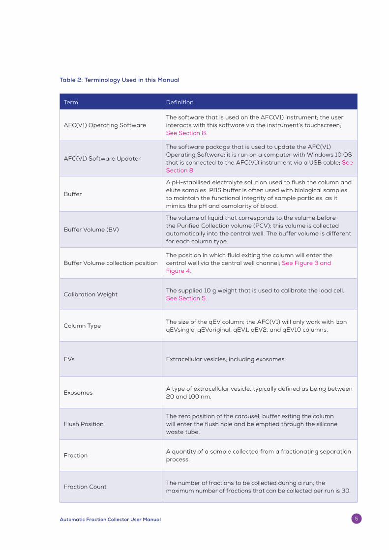
Term Definition
AFC(V1) Operating SoftwareThe software that is used on the AFC(V1) instrument; the user interacts with this software via the instrument’s touchscreen; See Section 8.
AFC(V1) Software Updater
The software package that is used to update the AFC(V1) Operating Software; it is run on a computer with Windows 10 OS that is connected to the AFC(V1) instrument via a USB cable; See Section 8.
Buffer
A pH-stabilised electrolyte solution used to flush the column and elute samples. PBS buffer is often used with biological samples to maintain the functional integrity of sample particles, as it mimics the pH and osmolarity of blood.
Buffer Volume (BV)
The volume of liquid that corresponds to the volume before the Purified Collection volume (PCV); this volume is collected automatically into the central well. The buffer volume is different for each column type.
Buffer Volume collection position The position in which fluid exiting the column will enter the central well via the central well channel; See Figure 3 and Figure 4.
Calibration WeightThe supplied 10 g weight that is used to calibrate the load cell. See Section 5.
Column TypeThe size of the qEV column; the AFC(V1) will only work with Izon qEVsingle, qEVoriginal, qEV1, qEV2, and qEV10 columns.
EVs Extracellular vesicles, including exosomes.
ExosomesA type of extracellular vesicle, typically defined as being between 20 and 100 nm.
Flush Position The zero position of the carousel; buffer exiting the column will enter the flush hole and be emptied through the silicone waste tube.
Fraction A quantity of a sample collected from a fractionating separation process.
Fraction CountThe number of fractions to be collected during a run; the maximum number of fractions that can be collected per run is 30.
Table 2: Terminology Used in this Manual
Automatic Fraction Collector User Manual 5

Term Definition
Fraction Volume The volume of each fraction collected during a run; there are pre-set fraction volumes for each column type; See Section 7.
Gel TypeAll qEV columns come with either 35 nm or 70 nm gel; See Section 6.
Lighting
There are two light modules on the AFC(V1), the “tower” which corresponds to the vertical portion of the AFC(V1) behind the qEV column mount, and the “halo” which corresponds to the horizontal base beneath the carousel; See Section 5.
Load Cell The component of the AFC(V1) that measures the weight of each fraction; the load cell is calibrated using the 10 g calibration weight; See Section 5.
Nozzle The area from which fluid exits the qEV column.
Nozzle SetThe entirety of the nozzle tip, a piece of silicon tubing, and the adapter used to connect qEV columns is called the nozzle set.
Purified Collection Volume (PCV)The volume immediately suceeding the buffer volume, containing particles of interest purified from the loaded sample. The PCV is different for each column type.
qEV ColumnThe type of column that is used with the AFC(V1); these columns are manufactured with an embedded RFID chip; the AFC(V1) is not intended to be used with any other column.
USB CableThe USB 2.0 Type A to USB 2.0 Micro cable (male to male) that is provided with the AFC(V1) instrument.
www.izon.com6

SAFETY AND HAZARDS2Safe Use Requirements and Specifications
Table 3: Safe Use Requirements and Specifications
Hazards
The AFC(V1) is a laboratory product. However, if biohazardous samples are present, adhere to current Good Laboratory Practices (cGLP) and comply with any local guidelines specific to your laboratory and location.
Disposal of Biohazardous Material
The AFC(V1) system contains no potentially hazardous biological materials, however the qEV columns are delivered containing < 0.1% sodium azide, which is potentially fatal if swallowed or in contact with skin. Please review the following guidelines and precautions prior to each use of the qEV column, especially if flushing with an antimicrobial buffer before storage (recommended).
Prevention:
– Do not get into eyes, on skin, or on clothing.
– Wash skin thoroughly after handling.
– Do not eat, drink, or smoke when using this product.
Safe Use Requirement Specification
Operating Temperature
Indoor Use Ambient temperature of 5-25 ˚C
Altitude Up to 2,000 metres above sea level
Relative Humidity 20-80% relative humidity
Power Consumption 15 W
Ingress Protection IP30
Pollution Degree Rating Pollution Degree 2
Power Supply Unit
(ATS024T- A120)
Input AC100-240 V 0.58 A 50/60 Hz
Output DC12 V nom 2 A max current 24 W max power
Automatic Fraction Collector User Manual 7

– Avoid release of product into the environment.
– Wear protective gloves and clothing; follow general laboratory precautions.
Response
– IF SWALLOWED: immediately call a POISON CONTROL CENTRE/Doctor/Hospital.
– IF ON SKIN: Gently wash with plenty of soap and water and immediately call a POISON CONTROL CENTRE/Doctor/Hospital.
– Remove immediately any contaminated clothing and wash before reuse.
– Collect any spillage and dispose of appropriately.
For more information, see the MSDS Documentation for Izon qEV columns: izon.com/sds
Sodium Azide can be fatal if swallowed or in contact with skin. It can cause damage to neurological organs through prolonged or repeated exposure. It is very toxic to aquatic life with long lasting effects.
Be sure to adhere to the following guidelines and comply with any local guidelines specific to your laboratory and location regarding use and disposal.
General Precautions:
– Always wear laboratory gloves, coats, and safety glasses with side shields or goggles.
– Keep your hands away from your mouth, nose, and eyes.
– Completely protect any cut or abrasion before working with potentially infectious or hazardous material.
– Wash your hands thoroughly with soap and water after working with any potentially infectious or hazardous material before leaving the laboratory.
– Remove watches and jewellery before working at the bench.
– The use of contact lenses is not recommended due to complications that may arise during emergency eye-wash procedures.
– Before leaving the laboratory, remove protective clothing.
– Do not use a gloved hand to write, answer the telephone, turn on a light switch, or physically engage people without gloves.
– Change gloves frequently.
– Remove gloves immediately when they are visibly contaminated.
– Do not expose materials that cannot be properly decontaminated to potentially infectious or hazardous material.
– Upon completion of the tasks involving potentially infectious or hazardous materials, decontaminate the work area with an appropriate disinfectant or cleaning solution (1:10 dilution of household bleach is recommended).
Dispose of the following potentially contaminated materials in accordance with laboratory local, regional, and national regulations:
– Biological Samples
www.izon.com8

– Reagents
– Used reaction vessels or other consumables that may be contaminated
Chemical Hazards
The AFC(V1) system contains no potentially hazardous chemical materials.
However, when the appropriate qEV column is used on the AFC(V1) system, the user is potentially exposed to a dilute solution of Sodium Azide from the column and/or waste hose outlet. Refer to page 7 of this manual under the heading “Disposal of Biohazardous Material” for guidlines and precautions to mitigate the risk of exposure to Sodium Azide.
Explosive or Flammability Hazards
The AFC(V1) poses no uncommon hazard related to flammability or explosion when used in a proper manner as specified by Izon Science Ltd.
Mechanical Hazards
The carousel is capable of moving during sample collection, calibration, and when the unit returns to the home postition. Please keep fingers and loose clothing clear, and refrain from removing the carousel cover when the unit is in operation.
Electrical Hazards
The AFC(V1) poses no uncommon electrical hazard to operators if installed and operated properly without physical modification and connected to a power source of proper specification.
The user is protected from hazardous voltage with power adaptor double insulation.
Use only the power supply unit provided with this product. Specification of unit is detailed in Table 3.
The AFC(V1) system is to be installed indoors and positioned away from any fluids.
Transport
Before moving or shipping the AFC(V1), decontamination procedures must be performed. Always move or ship the AFC(V1) with the supplied packaging materials which will protect the instrument from damage. If appropriate containers cannot be found, contact your local Izon Science office.
Storage
The AFC(V1) system can be stored under the following conditions:
– Temperature range: 0 to 60 ˚C
– Relative humidity: maximum 80%
Disposal
The AFC(V1) system contains electronic or electrical materials; it should be disposed of as unsorted waste and must be collected separately, according to the European Union Directive: Waste Electrical and Electronic Equipment – WEEE Directive. The user is fully responsible for ensuring that the obsolete Equipment and/or Consumables are recycled or disposed of in accordance with this and/or any other relevant laws and regulations in the countries where the instrument is being recycled or disposed of. Alternatively, obsolete Equipment and/or Consumables may be returned to your local Izon Science representative to be processed appropriately. Contact your local Izon Science representative for more information.
Automatic Fraction Collector User Manual 9

INTRODUCTION TO THE AUTOMATIC FRACTION COLLECTOR V1 (AFC)
3
Overview
Isolation of extracellular vesicles (EVs) using the combination of qEV size-exclusion columns and the Automatic Fraction Collector (AFC) increases uniformity of collected volumes, decreases experimental run-time, and eliminates many of the inaccuracies that are inherent in the manual collection of the PCV. The AFC(V1) offers users the ability to scale up EV isolation through automation of several steps, including the equilibration, PCV elution, washout, and regeneration of the columns.
The AFC(V1) manages the collection of fractions from the column by automatically differentiating between the buffer volume (pink area in Fig. 1) and the volume of the fractions containing EVs. The buffer volume does not contain any EVs and is emptied into the central well of the carousel. The type of qEV column used in each run will determine the volume of liquid that is emptied into the central well. Once the buffer volume has been collected, the instrument will begin collecting a predetermined number of fractions of a given volume as set by the user. The fractions after the buffer volume correspond to the PCV (blue zone in Fig. 1).
10 www.izon.com

The AFC(V1) measures the volume of each fraction by weight as it fills with liquid eluting from the column. When the designated threshold weight is reached, the fluid flow is automatically stopped to prevent dripping of fluid during repositioning of the carousel.
The type of qEV column used in each run will depend on the user’s preferences and research applications. For more information on which column to use, see Section 6: qEV Specifications and for more information on choosing a collection schedule, see Section 7: Choosing Run Parameters.
Intended Use:
The AFC(V1) is used to automate fraction collection of Izon’s qEV size-exclusion columns.
The instrument is intended to be used in research laboratories by professional personnel for research purposes only. Neither the AFC(V1) nor the qEV column are intended for diagnostic purposes and should not be used to make treatment decisions.
For verification of the entire system, it is recommended that Good Laboratory Practices (GLP) be followed to ensure reliable analyses.
Figure 1: Typical elution profile for the qEVoriginal. Larger extracellular vesicles (EVs) and exosomes elute first, while smaller vesicles and protein complexes elute later; 500 µL of bovine plasma on a qEVoriginal; concentration of EVs measured with a qNano and TRPS; concentration of proteins measured with spectrophotometry.
*Volumes are labelled as the highest volume in that sample i.e label “0.5” refers to the volume from 0.0-0.5 mL after the buffer volume, label “1.5” refers to the volume from 1.0-1.5 mL after the buffer volume and so on.
Volume (mL)
0.25
0.15
0.30
0.20
0.10
0.05
0.00
1.4
1.0
1.6
1.2
0.8
0.6
0.4
0.0
0.2
Con
cent
rati
on (E
Vs/
mL
x 10
10)
Pla
sma
pro
tein
(Ab
s 2
80
nm
)
Buffer Volume PCV
0.5 1.5 6.55.54.53.52.5
Automatic Fraction Collector User Manual 11

1 AFC(V1) Instrument with attached nozzle set and silicone waste tube
2 Nozzle Set (x3)
3 qEV Column Mount (x5)
4 Carousel Cover
5 Reversible Carousel
6 Carousel Plate
7 qEVoriginal Reservoir
8 5.0 mL Collection Tube (x15)
9 2.0 mL Collection Tube (x30)
10 12-volt Power Supply
11 Power Lead
12 USB 2.0 Type A to USB 2.0 Micro cable (male to male)
13 10 g Calibration Weight
INSTRUMENT SPECIFICATIONS4
Instrument Layout
The following components are provided in the box.
Table 4: Components of the AFC(V1) System
www.izon.com12
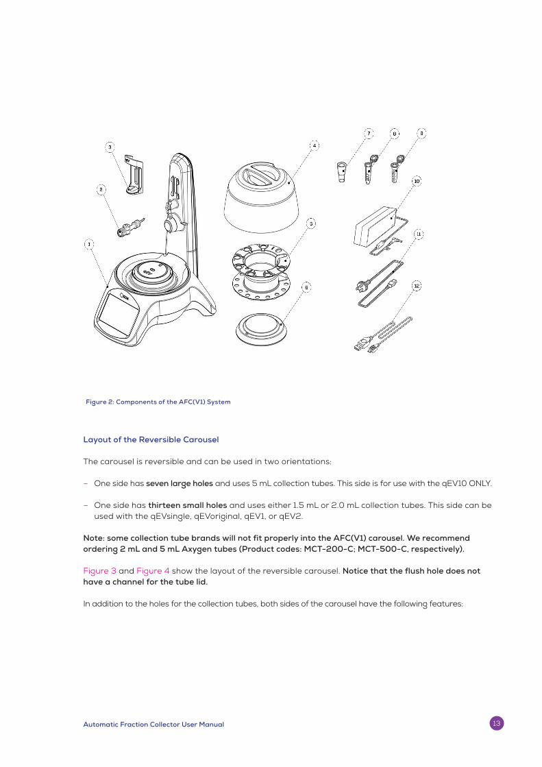
Figure 2: Components of the AFC(V1) System
Layout of the Reversible Carousel
The carousel is reversible and can be used in two orientations:
– One side has seven large holes and uses 5 mL collection tubes. This side is for use with the qEV10 ONLY.
– One side has thirteen small holes and uses either 1.5 mL or 2.0 mL collection tubes. This side can be used with the qEVsingle, qEVoriginal, qEV1, or qEV2.
Note: some collection tube brands will not fit properly into the AFC(V1) carousel. We recommend ordering 2 mL and 5 mL Axygen tubes (Product codes: MCT-200-C; MCT-500-C, respectively).
Figure 3 and Figure 4 show the layout of the reversible carousel. Notice that the flush hole does not have a channel for the tube lid.
In addition to the holes for the collection tubes, both sides of the carousel have the following features:
Automatic Fraction Collector User Manual 13

The following components are required for operation and/or maintenance of the instrument but are not provided:
– Computer with Windows 10 OS for updating the AFC(V1) operating firmware.
– A qEV column.
– Pipettes and tips.
– Freshly prepared and 0.22 µm filter-sterilised buffer.
– Freshly prepared 0.5 M NaOH solution for cleaning.
– 70% Ethanol solution for cleaning.
Sample Buffer Recommendations:
– Buffer temperature should be within the operational temperature of 18-24 ˚C (65-75 ˚F).
– Use a buffer with an ionic strength of 0.15 M or greater to avoid any unwanted ionic interactions between the solute molecule and the matrix.
– qEV columns come equilibrated in filtered PBS containing < 0.1% w/v sodium azide.
– To maintain the functionality of EVs, the buffer used with the columns should be of the same ionic strength and pH as the original sample buffer.
A Central Well
B Central Well Channel
C Flush Hole
Figure 3: Layout of the carousel with large holes Figure 4: Layout of the carousel with small holes
C
B
AA
C
B
www.izon.com14

ASSEMBLY AND SETUP INSTRUCTIONS5
Instrument Power and General Operating Procedures
– Make sure power supply box is positioned away from fluids.
– To prevent heat build-up, do not cover the power supply box.
– Position unit so it can be quickly and easily disconnected from the mains power.
– Check the local supply meets the AC input requirement given in the specification.
Izon instruments are only to be operated with Izon supplied leads and power supplies. Failure to use the correct power supply may result in invalid operation.
Make sure the power supply is placed away from the instrument and to the rear of the instrument to avoid coming into contact with any spills or fluid.
General Operating Procedures
– For indoor use only and to be used within the rated conditions noted in system specifications.
– Take care not to spill any fluids on electrical parts during operation.
Assembling and Installing the AFC(V1)
1. Unpack the AFC(V1) and box contents.
We recommend that you save the box and packaging materials in case the instrument needs to be returned for servicing.
If you choose not to save the materials, please recycle them wherever cardboard recycling services are provided.
The AFC(V1) has a sensitive weight scale and should not be installed near any equipment that causes vibrations, such as centrifuges, culture and plate shakers, vortex mixers, sonication devices, etc. as this could negatively impact the load cell measurements.
Automatic Fraction Collector User Manual 15

2. Place the AFC(V1) onto a stable and level laboratory bench.
3. Ensure that the clear silicon waste tube of the AFC(V1) exits from the rear or side of the instrument and empties into a sink or waste bottle.
4. Connect the power lead to the 12-volt power supply.
5. Plug the 12-volt power supply into the rear of the instrument.
6. Plug the power lead into a wall socket.
7. Turn on the instrument using the power switch at the rear. The screen will light up briefly showing the IZON logo and the carousel will rotate to its zero position. Ensure the valve is in place, as shown Figure 5 below:
Figure 5: AFC(V1) valve in position
Aligning the Carousel
After the instrument has been assembled on a level surface, the carousel must be aligned with the fluid nozzle. If the fluid nozzle is already above the flush hole (See Figure 7), then this step may be skipped.
1. Press SETUP on the left-hand side of the main screen as shown in Figure 6 below:
Figure 6: Press SETUP on the main menu screen
www.izon.com16

2. Following the screen, choose CAROUSEL > CALIBRATE
3. Press the -/+ buttons (for fine alignment) and --/++ buttons (for coarse alignment) until the nozzle is positioned directly above the hole in the flush position as shown in Figure 7 below.
Figure 7: The nozzle tip centred over the flush hole. Note that for the side of the carousel that holds 2 mL tubes, the flush hole will be on the right of the central well channel. For the other side of the carousel that holds 5 mL tubes, the flush hole is on the left of the central well channel.
4. Once the flush hole has been aligned with the nozzle, press SET ZERO. You will then return to the main setup screen.
Improper calibration of the carousel can cause drops from the nozzle to land on the carousel or miss collection tubes. If this occurs, simply recalibrate the carousel. For more information, please refer to the Troubleshooting Guide.
Automatic Fraction Collector User Manual 17
Calibrating the Load Cell
The AFC(V1) load cell measures the weight of each fraction to determine its volume and ensures uniform volumes across all fractions. Calibration is performed using the supplied 10 g weight.
Calibration of the Load Cell
1. From the main menu, press SETUP > SCALE > CALIBRATE, and follow the instructions on the screen.
2. When instructed, place an empty carousel onto the AFC(V1) and press OK.
3. The lighting will change to red to indicate that the instrument is measuring the weight of the carousel.
Once the measurement process has started, the user should not bump or interfere with the carousel until the lighting has changed back to green to indicate that the process is complete. Any interference will require the user to restart the calibration process.
4. Once the measurement is complete, the lighting will change to green and the screen will instruct the user to place the 10 g calibration weight onto the centre of the empty carousel.
5. Ensure that the weight is completely still BEFORE pressing OK to continue.
6. The lighting will then change to red to indicate that the instrument is measuring the calibration weight.
7. Once the load cell calibration is complete, the user will be taken back to the setup menu.
8. Press EXIT to return to the main screen.
Calibration of the load cell should be completed on first use, after every software update,
and if your fraction volumes are being measured inconsistently. For more information, please refer to the Troubleshooting Guide.
Adjusting Lighting Settings
The user can choose whether to leave the tower and halo lights on or off through the Setup Menu.
1. From the main menu, press SETUP > LIGHTING.
2. On the following screen, select or deselect the tower or halo lighting modules.
www.izon.com18

Column Type qEVsingle qEVoriginal qEV2 qEV10
Optimal Sample Loading Volume1
150 µL 500 µL 2 mL 10 mL
Reusability No, single useYes, up to 5 times
Yes, up to 5 times
Yes, up to 5 times
Column Volume 3.5 mL 9.6 mL 45.1 mL 69.3 mL
Buffer Volume2qEV/35
0.8 mL
qEV/70
1.03 mL2.7 mL 14.1 mL 21.4 mL
Flush Volume 3.5-4.0 mL 20.0 mL 90.0 mL 140.0 mL
Optimal Fraction Size 200 µL 500 µL 2.0 mL 5.0 mL
0.5 M NaOH required per clean N/A 10 mL 2 mL 5 mL
Buffer required per clean N/A 20.0 mL 120.0 mL 240.0 mL
Buffer reservoir required No Yes Yes Yes
Collection tube size 1.5 or 2.0 mL 1.5 or 2.0 mL 1.5 or 2.0 mL 5.0 mL
qEV SPECIFICATIONS6
Choosing the right qEV column to run will depend on the volume of the sample and the target isolation range of the analyte.
Table 5: qEV Legacy Column Specifications
1Loading a lesser volume than the optimal sample loading volume will result in higher sample dilution, while loading a higher volume can overload the column matrix and cause contamination of the purified sample in the PCV.
2Buffer volumes stated are exclusive of an additional 0.25 mL from the buffer volume inside the nozzle set.
3EVs and similarly sized particles have been detected from 0.8 mL on a qEVsingle/70 column, however the concentration is extremely low and may cause significant sample dilution if included.
Automatic Fraction Collector User Manual 19

Table 6: qEV Gen 2 Column Specifications
1Loading a lesser volume than the optimal sample loading volume will result in higher sample dilution, while loading a higher volume can overload the column matrix and cause contamination of the purified sample in the PCV.
2Buffer volumes stated are exclusive of an additional 0.25 mL from the buffer volume inside the nozzle set.
Column Type qEVoriginal qEV1
Optimal Sample Loading Volume1
500 µL 1 mL
ReusabilityYes, up to 5 times
Yes, up to 5 times
Column Volume 8.5 mL 13.5 mL
Buffer Volume2 2.5 mL 4.0 mL
Flush Volume 17 mL 27 mL
Optimal Fraction Size 400 µL 700 µL
0.5 M NaOH required per clean 8.5 mL 13.5 mL
Buffer required per clean 17 mL 27 mL
Buffer reservoir required Yes Yes
Collection tube size 1.5 or 2.0 mL 1.5 or 2.0 mL
www.izon.com20

qEV/35nm Series qEV/70nm Series
Target Particle Size 35 nm to 350 nm 70 nm to 1000 nm
Optimum Recovery Range Particles < 110 nm Particles > 110 nm
Isolation Ranges:
All qEV columns are available in one of two isolation ranges, the qEV/35nm series and the qEV/70nm series. The qEV/35nm series of columns generally perform better when the target particle to be isolated is less than 110 nm in diameter, while the qEV/70nm series of columns generally perform better when the target particle to be isolated is greater than 110 nm in diameter (see Fig. 8).
Table 7: Specifications of qEV/35nm and qEV/70nm Series
Figure 8. Comparison of total protein elution levels and recovery of 57 nm particles between a
qEVoriginal/35nm Legacy and a qEVoriginal/70nm Legacy.
*Volumes are labelled as the highest volume in that sample i.e label “0.5” refers to the volume from 0.0-0.5 mL after the buffer volume, label “1.0” refers to the volume from 0.5-1.0 mL after the buffer volume and so on.
2.0
qEV-70 particles
qEV-70 protein
qEV-35 particles
qEV-35 protein
2.5 3.01.50.5 3.51.00
0
0.10
0.45
0.35
0.25
0.40
0.30
0.20
0.15
1.0
0.9
0.7
0.5
0.8
0.6
0.4
0.2
0.3
0.1
Volume (mL)*
Ab
sorb
anc
e a
t 3
50
nm
Pla
sma
pro
tein
(Ab
s 2
80
nm)
Buffer Volume PCV
0
Column Type qEVoriginal qEV1
Optimal Sample Loading Volume1
500 µL 1 mL
ReusabilityYes, up to 5 times
Yes, up to 5 times
Column Volume 8.5 mL 13.5 mL
Buffer Volume2 2.5 mL 4.0 mL
Flush Volume 17 mL 27 mL
Optimal Fraction Size 400 µL 700 µL
0.5 M NaOH required per clean 8.5 mL 13.5 mL
Buffer required per clean 17 mL 27 mL
Buffer reservoir required Yes Yes
Collection tube size 1.5 or 2.0 mL 1.5 or 2.0 mL
4.0 4.5
Automatic Fraction Collector User Manual 21

OPERATING INSTRUCTIONS7Choosing Run Parameters
Carousel Side Selection
The carousel is reversible and can be used in two orientations:
– One side has seven large holes and uses 5 mL collection tubes. This side is for use with the qEV10 ONLY.
– One side has thirteen small holes and uses either 1.5 mL or 2.0 mL collection tubes. This side can be used with the qEVsingle, qEVoriginal, qEV1, or qEV2.
– Again, please note that some collection tube brands will not fit properly into the AFC(V1) carousel. We recommend ordering 2 mL and 5 mL Axygen tubes (Product codes: MCT-200-C; MCT-500-C, respectively).
The maximum number of fractions that can be collected per run is 30. If you have chosen a fraction count that is larger than the carousel’s capacity, the run will pause after the last fraction on the carousel has been filled and then wait for you to replace the tubes on the carousel.
Tube Type Selection
Each side of the carousel is designed to hold a specific tube size. The carousel side with small holes is designed be used with either 1.5 mL or 2.0 mL collection tubes.
Be sure that you load the carousel with the collection tube that will hold your required fraction size. For example, if you have chosen a fraction size of 2.0 mL, then 2.0 mL collection tubes must be used.
Fraction Size Selection
Each column type has pre-determined options for fraction volume, as shown in Tables 8 and 9.
Table 8: Optional Selections for Legacy Column Fraction Size
qEVsingle qEVoriginal qEV2 qEV10
Max Number of Fractions 30 30 30 30
Min Number of Fractions 1 1 1 1
Max Fractions in a single Carousel 13 13 13 7
Max Fraction Volume 2.0 mL 2.0 mL 2.0 mL 5.0 mL
Min Fraction Volume 0.2 mL 0.5 mL 2.0 mL 5.0 mL
Fraction Volume Increments 0.2 mL 0.5 mL N/A N/A
www.izon.com22

Setting Up a Run
Mounting the qEV Column to the AFC(V1) Tower
The AFC(V1) comes with a column mount for each compatible column type. Choose the column mount that matches the type of column you would like to use. Once a qEV column and column mount have been attached to the AFC(V1), the column type is determined automatically and is displayed on the AFC(V1) touchscreen.
The AFC(V1) will only work with RFID-tagged qEV columns. Do not attempt to use un-tagged or non-Izon columns with the AFC(V1) instrument.
1. Turn on the instrument by switching on the power button at the rear of the instrument.
2. Before a column has been inserted or if a column without an RFID tag has been inserted, the tower lighting will be white, and the main screen will display “No Column” as shown in Figure 9 below.
Figure 9: Main screen when no column is attached to the AFC(V1)
Table 9: Optional Selections for Gen 2 Column Fraction Size
qEVoriginal Gen 2 qEV1
Max Number of Fractions 30 30
Min Number of Fractions 1 1
Max Fractions in a single Carousel 13 13
Max Fraction Volume 2.0 mL 1.4 mL
Min Fraction Volume 0.4 mL 0.7 mL
Fraction Volume Increments 0.4 mL 0.7 mL
Automatic Fraction Collector User Manual 23

3. Fit the appropriate column mount onto the AFC(V1) tower.
4. If using a qEV1, qEVoriginal or qEVsingle, remove the top cap prior to removing the lower Luer cap of the column, then proceed to step 5. If using a qEV2 or qEV10, fit the reservoir to the column and ensure the fluid is flowing properly before proceeding to step 5.
5. Insert the column from above into the column mount, then remove the lower cap and carefully dock the column. Ensure that the IZON logo on the column is facing away from the AFC(V1) tower as shown in Figure 10 below.
Figure 10: A qEV original/70nm Legacy column loaded correctly onto the AFC(V1). Ensure that the IZON logo is facing away from the AFC(V1) tower.
6. Turn the column within the column mount until the type of qEV column used is displayed on the touchscreen as shown in Figure 11 below.
Figure 11: Main screen when a column is attached.
Ensure that the connection between the column and the valve is secure to avoid any leakage.
It is common for a few drops of buffer to be spilled while connecting the column to the tube adaptor on the valve. To minimise this, make the connection quickly and be sure to wipe up any drops that land on the instrument.
www.izon.com24

Column Use Counter and Invalid Columns
The AFC(V1) instrument records the number of times that each column has been used. The columns are intended to be used up to five times.
A warning indicator will be displayed when the recommended number of uses is approaching the maximum and after this number has been exceeded, as shown below in Figure 12. The AFC(V1) will also provide guidance on how many column uses are left before the column becomes invalid.
Figure 12: A warning indicator shows how many uses a column has left.
A column will become invalid once it has been used 10 times. The AFC(V1) will not run invalid columns, which will be indicated as shown below in Figure 13.
Figure 13: The home screen displaying the error message when a column has been used 10 times.
Automatic Fraction Collector User Manual 25

Adjusting the Collection Schedule and Buffer Volume
Once the appropriate column has been selected and mounted to the AFC(V1) tower, the collection schedule must be set.
1. From the main screen, press COLLECTION SCHEDULE as shown in Figure 14 below.
Figure 14: Location of the collection schedule menu.
2. From this screen, you can adjust the fraction number, fraction size and buffer volume size for collection. There are several fraction size options available depending on the column type. Press -/+ to choose your collection count, collection size and buffer volume size as shown in Figure 15 below. To change the adjusted buffer volume from the default value, deselect the DEFAULT BV button.
Figure 15: The Collection Schedule menu.
The default buffer volume is the volume before the PCV. The system will take into account the volume inside the nozzle tubing of 0.284 mL. Therefore if you are not collecting a buffer volume, there will be 0.284 mL collected. If you are collecting any buffer volume size, 0.284 mL will be collected on top of the chosen buffer volume.
3. Press X to save your parameters and return to the main menu.
4. When you are ready to start your collection, press START COLLECTION and review your collection parameters.
www.izon.com26

Figure 16: The location of the “Start Collection” option.
5. Press YES to proceed to carousel setup or NO to return to the main menu.
Setting up the Carousel
Once you have defined your collection parameters, you are ready to prepare the carousel for collection.
Be sure to label collection tubes prior to loading them onto the carousel.
1. Load the collection tubes onto the carousel in the appropriate orientation.
2. Ensure that you have loaded enough tubes for your collection protocol.
3. Gently place the carousel onto the carousel plate. Ensure that the carousel alignment hole engages with the raised carousel alignment pin on the carousel plate as shown in Figure 17 below.
Figure 17. The alignment pin correctly engaged in the carousel.
Always load the required tubes into the carousel with the lids facing inwards as shown in Figure 17. Ensure that the lids of the tubes are not in contact with the carousel cover, or the weight scale may not function properly.
Automatic Fraction Collector User Manual 27

Initiating a Run
Once the carousel has been loaded, the instrument will walk through the column preparation steps before initiating the collection.
Flushing the Column
1. The next screen will ask you to mount the column reservoir. If using a qEVoriginal, qEV2, or qEV10 column, mount the reservoir if you have not already fitted it. Figure 18 below shows the qEVoriginal column as an example. If using a qEVsingle, a column reservoir is not needed. Using a reservior is optional for the qEV1 but may be desirable depending on liquid volume, if this is the case then the qEVoriginal reservior is compatible.
Figure 18: A column reservoir on a qEVoriginal column.
2. Press OK to continue.
3. The next screen will ask you whether you would like to flush the column. We recommend flushing of all columns with fresh, filtered PBS buffer (See Section 6: qEV Specifications for information on buffer requirements).
a Press YES if you would like to flush the column and ensure that you have the appropriate amount of buffer for the column type.
b Press NO if the column has already been flushed. The next screen will ask you to prime the column.
4. While the AFC(V1) is in flushing/priming mode, the carousel will be in the flush position and the buffer will flow out of the column and through the flush hole in the carousel, to be pumped out through the waste tube (see Figure 3 and Figure 4). Press OK to continue.
www.izon.com28

Please check to make sure that the silicone waste tube at the back of the instrument is draining into a sink or suitable waste reservoir close to the instrument.
5. Press OK when the column has been flushed/primed with the recommended volume of buffer.
6. The next screen will prompt the user to place the carousel cover over the AFC(V1). The cover protects the carousel from being inadvertently bumped during operation. Press OK to continue.
Always load the required tubes into the carousel with the lids facing inwards. Ensure that the lids of the tubes are not in contact with the carousel cover.
Sample Loading and Initiating Collection
7. The next screen will ask you to have sufficient buffer available to run the column and to load the sample. For sample loading and buffer requirements for each column type, see Section 6: qEV Specifications. Ensure that there is no residual buffer left on the top of the column (remove any excess with a pipette) before adding the sample. Failure to do this may result in dilution of the sample. Press OK to continue. It is important to only load the sample at this point, let it run through until the flow stops, and then top up the reservoir with the appropriate amount of buffer (displayed on the screen). Adding buffer at the same time or before the sample has fully entered the frit of the column will dilute the sample and change the elution profile.
8. Press OK to continue. The column will start running and the carousel will move to the buffer volume collection position. The buffer volume will then begin collecting into the central well of the carousel and the lighting will change to red to indicate that the process has started.
9. When the sample has fully entered the upper frit of the column, top up the reservoir with the correct amount of buffer to resume collection of the buffer volume.
10. When the buffer volume has been collected, the carousel will move to position 1, collecting the specified volume and then progressively move to collect each successive individual fraction. If more collection tubes are required than the fully loaded carousel, the user will be instructed when to remove the cover and carousel, replace the tube positions with fresh tubes and continue the run.
Automatic Fraction Collector User Manual 29

Completing a Run
After a run has been completed, it is important to clean the column to ensure there is no carryover between samples. The AFC(V1) will guide the user through this process via on screen instructions.
11. When the final fraction has been collected, the display lighting will turn green and the carousel will return to the waste position. The carousel cover and the collection tubes can now be safely removed.
12. If using a qEVsingle, pressing OK will return the user to the home screen as these are not reusable. For all other column types the user will be asked if they wish to clean the column.
13. Select NO to return to the main screen and begin another run without cleaning. This is not recommended.
Remember to empty and clean out the carousel central well between consecutive runs.
14. Select YES to be guided through the cleaning process before being returned to the home screen.
The nozzle should be flushed thoroughly with a 70% ethanol solution after the last run of the day to prevent the growth of bacteria within the tubing. Remove the column from the AFC(V1) tower during the flushing stage (as the solenoid valve will still be open during the flushing step) and use a Pasteur pipette or Nalgene squeeze bottle to flush the nozzle with 70% ethanol.
AFC(V1) Shut Down
15. Before turning off the AFC(V1), rinse the AFC(V1) nozzle using DI water with the valve open. This will prevent salt crystallising in the tip of the nozzle while it is not in use.
16. Switch off the AFC(V1) at the rear of the instrument.
www.izon.com30
RESOURCES8
Repair and Servicing of AFC(V1) Instrument
– All replacement parts must be obtained via Izon Science Ltd.
– Contact your regional Izon Science representative for replacement parts.
We recommend that you save the box and packaging materials in case the instrument needs to be returned for servicing.
Updating the AFC(V1) Software
The software on the AFC(V1) instrument (AFC Operating Software) should be updated periodically. If a software update is required, an email alert will be sent out to notify the user that an update has been released. It is recommended to check for available updates at least once every six months. There are two software modules that are used:
1. AFC(V1) Operating Software: this is the software that is used on the AFC(V1) instrument; the user interacts with this software via the instrument’s touchscreen.
2. AFC(V1) Software Updater: this is a software package that is used to update the AFC(V1) Operating Software; it is run on a computer with Windows 10 OS that is connected to the AFC(V1) instrument via a USB cable.
Requirements for Updating the AFC(V1) Operating Software
1. A computer that is running Windows 10 or later and is connected to the internet.
2. The USB cable provided with the AFC(V1) instrument.
3. The latest version of AFC(V1) Updater Software: www.izondownload.com/AFC/updates/AFC_Updater_Install.exe
Downloading and Installing the AFC(V1) Software Updater
The software updater can be downloaded onto any computer running Windows 10 or later. Once installed, the AFC(V1) Software Updater will automatically check for the latest version of AFC(V1) Operating Software that is available.
The computer used to update the AFC(V1) Operating Software MUST be connected to the internet in order to download the latest version of the software.
Automatic Fraction Collector User Manual 31

1. Download the AFC(V1) Software Updater using the link shown previously.
2. Install the AFC(V1) Updater Software by following the instructions on your screen.
3. Once installed, the AFC(V1) Software Updater will automatically check to see if the latest version of the AFC(V1) Operating Software has been downloaded. If an update is available, the Software Updater will display the release notes for the latest version as shown in Figure 19 below.
a Press SKIP UPDATE to prevent the download of the updated AFC(V1) Operating Software.
b Press GET UPDATE to download the latest version of the AFC(V1) Operating Software.
Figure 19: Click GET UPDATE to download the latest version of the AFC(V1) Operating Software.
Updating the AFC(V1) Operating Software
To update the AFC(V1) Operating Software, the AFC(V1) must be connected to a computer with the AFC(V1) Software Updater installed.
1. Ensure that the AFC(V1) Software Updater program is closed.
The updater will only work if the AFC(V1) Software Updater program is opened after the AFC(V1) has been connected to the computer.
2. Switch the AFC(V1) on.
3. Connect the computer to the rear of the AFC(V1) instrument using the provided USB cable.
4. Open the AFC(V1) Software Updater.
5. The AFC(V1) Software Updater will automatically check for the latest version of the Operating Software. Click GET UPDATE to download the latest version.
6. Ensure that Automatic Fraction Collector is shown in the Device box, as shown in Figure 20.
www.izon.com32

Figure 20: The Izon AFC(V1) Update software with the AFC(V1) correctly selected in the “Port” dropdown box.
If no device is shown in the Device box, close the software and reopen it.
The precise name (COM port name) of each AFC(V1) will not be consistent across computers. It is common for this to change when the AFC(V1) is plugged into different computers and occasionally with the same computer. This does not affect the performance of the software update.
7. Press UPDATE AFC when you are ready to update the Operating Software.
8. Once the software update is complete, disconnect the USB cable and close the AFC(V1) Software Updater.
Maintenance of AFC(V1) Instrument
Calibration Testing
It is recommended to periodically test the load cell calibration to ensure the accuracy of fraction volumes. For instructions or recommendations on running a calibration validation test, please contact your regional Izon customer support representative.
Surface Decontamination
The following areas can be cleaned with 70% ethanol and a non-abrasive cloth or towel:
– Outer plastic shell of the AFC(V1) instrument
– The reversible carousel
– Carousel cover
– Column mount
– The touchscreen display should be cleaned with a gentle cloth and 70% ethanol.
Automatic Fraction Collector User Manual 33
To prevent electrical shock, always turn off and unplug the instrument prior to performing decontamination procedures.
Do not use abrasive or corrosive detergents or strong alkaline solutions. These agents can damage the plastic and metal components of the instrument.
Replacing the Nozzle
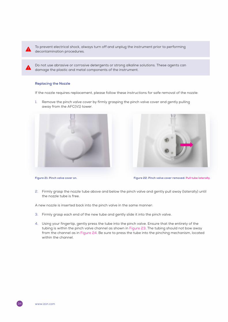
If the nozzle requires replacement, please follow these instructions for safe removal of the nozzle:
1. Remove the pinch valve cover by firmly grasping the pinch valve cover and gently pulling away from the AFC(V1) tower.
Figure 21: Pinch valve cover on. Figure 22: Pinch valve cover removed: Pull tube laterally.
2. Firmly grasp the nozzle tube above and below the pinch valve and gently pull away (laterally) until the nozzle tube is free.
A new nozzle is inserted back into the pinch valve in the same manner:
3. Firmly grasp each end of the new tube and gently slide it into the pinch valve.
4. Using your fingertip, gently press the tube into the pinch valve. Ensure that the entirety of the tubing is within the pinch valve channel as shown in Figure 23. The tubing should not bow away from the channel as in Figure 24. Be sure to press the tube into the pinching mechanism, located within the channel.
www.izon.com34
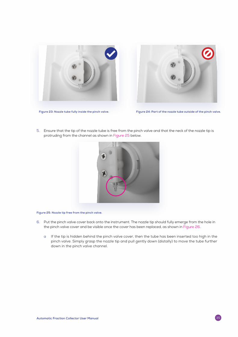
5. Ensure that the tip of the nozzle tube is free from the pinch valve and that the neck of the nozzle tip is protruding from the channel as shown in Figure 25 below.
Figure 25: Nozzle tip free from the pinch valve.
6. Put the pinch valve cover back onto the instrument. The nozzle tip should fully emerge from the hole in the pinch valve cover and be visible once the cover has been replaced, as shown in Figure 26.
a If the tip is hidden behind the pinch valve cover, then the tube has been inserted too high in the pinch valve. Simply grasp the nozzle tip and pull gently down (distally) to move the tube further down in the pinch valve channel.
Figure 24: Part of the nozzle tube outside of the pinch valve.Figure 23: Nozzle tube fully inside the pinch valve.
Automatic Fraction Collector User Manual 35

Figure 27: Nozzle tip hidden behind the pinch valve cover.
Figure 28. The AFC(V1) serial number and compliance sticker.
Figure 26: Nozzle tip fully emerging through the hole in the pinch valve cover.
When reporting AFC(V1) issues to [email protected], please provide the serial number of the AFC(V1), which can be found on the underside of the AFC(V1) as in Figure 28.
www.izon.com36

Troubleshooting
Table 10: Troubleshooting Common AFC(V1) Faults
Observation Fault Resolution
Device does not turn on Faulty power source or power lead.
Power connector is not fully plugged in.
Internal connections have loosened during transit.
Check the device is switched on and plugged in correctly. If there is still no power, try an alternative power source.
Contact Izon support to replace the power supply and/or power lead.
Contact Izon support if the unit flashes when turned on, but does not work. Please provide the serial number (underneath the unit).
Leakage from the column valve-to-column connection
Column is not connected securely to the valve.
Valve is damaged.
Check the column is fully pushed into the top of the valve.
Check the valve is not damaged, replacement parts can be found in the consumables box.
Leakage from the Luer connection or tubing
Tubing is not fully pushed into the valve.
Tubing is damaged.
Check the valve is securely connected into the Luer lock.
Check the tubing is fully pushed into the valve. Remove the valve cover and inspect the tubing, replacement parts can be found in the consumables box.
Dripping from the nozzle when the valve is closed
Tubing is not fitted in the valve correctly.
Valve is not working correctly.
Remove the valve cover and ensure the tubing is fitted in the channel of the pinch valve head properly.
If there is no clicking noise when the system starts up, this indicates a faulty valve.
Contact Izon support for a replacement valve.
Tower or halo lights are not working
Lights are turned off in the setup menu under LIGHTING.
Make sure the lights are on in the setup menu under LIGHTING if required.
The touchscreen is delivering wrong outputs
Two areas are touched simultaneously.
Screen is touched too quickly and/or too hard.
Make sure the desired area on the screen is touched centrally and firmly.
Use a pen/stylus to trigger a smaller area.
Do not touch the screen repetitively before a response is acknowledged.
Loud motor noise/crunching noise
Gear belt too loose or obstructed.
Contact Izon support.
Automatic Fraction Collector User Manual 37

Observation Fault Resolution
Fractions are skipped Fraction change is triggered by vibrations or something touching the carousel while the collection is in progress.
Place the device on a stable surface with minimal disturbances from other devices.
Ensure that the carousel cover is used, and the device is not bumped or touched during operation.
Incorrect fraction volumes and/or number of fractions, overflow of fractions
Fraction volumes and numbers are set incorrectly in the collection schedule.
Device is not on a stable surface.
Load cell calibration is incorrect.
Collection tube lids are touching the carousel cover.
Check the fraction volumes and numbers are correct in the collection schedule setup.
Make sure the device is placed on a stable surface with minimal disturbances from other devices.
Recalibrate the load cell on the device under the SETUP menu using a precise 10 g weight.
Ensure the collection tube lids are not touching the carousel cover. Note, this is more likely to occur on the carousel side with the large holes.
Droplets are catching on the valve cover
Nozzle is pushed back too far inside the valve.
Valve cover is too loose.
Check the nozzle is placed inside the channel of the valve head but not fully pushed in, the user should be able to see the nozzle tip outside of the valve cover.
Ensure the valve cover is fitted firmly over the valve head.
Droplets are catching on the carousel during the flushing procedure
Carousel is not aligned correctly.
Nozzle is bent.
Recalibrate the carousel alignment to the centre of the flush position and make sure to press SET ZERO.
Reposition the nozzle to a vertical position or replace. Replacements can be found in the consumables box, or at izon.com.
Spillage of liquid onto the table or overflow onto the area surrounding the carousel plate during the flushing procedure
Waste tubing to the pump is not connected or faulty.
Waste tubes or flush hole are obstructed.
Pump is faulty.
Waste tube not in waste container.
Make sure the waste tubes on the bottom of the device are connected and free of any obstruction. Ensure that the flush hole is not obstructed.
If the pump is silent during the flushing steps, contact Izon support.
Ensure that the free end of the tubing is in a waste container.
Column will not flow (during flushing or elution steps)
If using qEV2 or qEV10, a bubble can become trapped in between the top Luer connection and reservoir, impeding the fluid flow.
If using a qEVoriginal, qEV1 or qEVsingle, air trapped in the resin or the white frits may be impeding the flow.
If no sound can be heard during the flushing step, the pump will be faulty.
Ensure the reservoir is filled with buffer and flowing properly before connecting to the column.
Replace the column. Do not leave the columns without buffer on the top frit for more than 10 minutes. Always remove the top cap first, while the lower cap is still on.
Contact Izon support.
www.izon.com38
CONTACT US
Additional support material is available at support.izon.com
If you have any questions that are not answered on the support portal, please contact our support staff via the online support portal, or directly by email ([email protected]).
FCC Declaration of Conformance:
This device complies with part 15 of the FCC Rules. Operation is subject to the following two conditions:
(1) This device may not cause harmful interference
(2) This device must not accept any interference received, including interference that may cause undesired operation. Changes or modification not expressly approved by the party responsible for compliance could void the user’s authority to operate the equipment.
Rev OAutomatic Fraction Collector User Manual 39

Visit www.izon.com for more information.
FIND OUT MORE.