axial through-hole multilayer ceramic capacitors aximax, … · commercial grade products are...
TRANSCRIPT

© KEMET Electronics Corporation • P.O. Box 5928 • Greenville, SC 29606 • 864-963-6300 • www.kemet.com C1072_AXIMAX_X8L • 8/30/2017 1One world. One KEMET
Overview
KEMET’s Aximax conformally coated axial through-hole ceramic capacitors in X8L dielectric feature a 150°C maximum operating temperature and is considered "general purpose high temperature". These components are fixed, ceramic dielectric capacitors suited for high temperature bypass and decoupling applications or frequency discriminating circuits where Q and stability of capacitance characteristics are not critical. X8L exhibits a predictable change in capacitance with respect to time and voltage and boasts a minimal change in capacitance with reference to ambient temperature up to 125°C. Beyond 125°C X8L displays a wider variation in capacitance. Capacitance change is limited to ±15% from -55°C to +125°C and +15, -40% from 125°C to 150°C.
Driven by the demand for a more robust and reliable component, X8L dielectric capacitors were developed for critical applications where reliability at higher operating temperatures are a concern. These capacitors are widely used in automotive circuits as well as general high temperature applications.
In addition to commercial grade, automotive grade devices are available and meet the demanding Automotive Electronics Council's AEC-Q200 qualification requirements.
These devices meet the flame test requirements outlined in UL Standard 94V-0.
Axial Through-Hole Multilayer Ceramic Capacitors
Aximax, 400 Series, Axial, Conformally Coated, X8L Dielectric, 25 – 50 VDC (Commercial & Automotive Grade)
Ordering Information
C 410 C 105 K 3 N 5 T A 7200
Ceramic Style /Size
Specification/ Series
Capacitance Code (pF)
Capacitance Tolerance1
Rated Voltage (VDC)
Dielectric Design Lead Finish2
Failure Rate
Packaging/Grade (C-Spec)
410430
C = Standard Two significant digits and number of
zeros
J = ±5%K = ±10%M = ±20%
3 = 25 V5 = 50 V
N = X8L
5 = Multilayer
T = 100% Matte SnH = SnPb (60/40)
A = N/A Blank = Bulk7200 = 12" Reel 7293 = Ammo pack9170 = Automotive grade9170 7200 = Auto 12" Reel 9170 7293 = Auto Ammo pack
1 Additional capacitance Tolerance offerings may be available. Contact KEMET for details. 2 Lead materials:
Standard: 100% matte tin (Sn) with nickel (Ni) underplate and steel core ( “T” designation). Alternative1:60%tin(Sn)/40%lead(Pb)finishwithcopper-cladsteelcore(“H”designation). Additionalleadfinishoptionsmaybeavailable.ContactKEMETfordetails

© KEMET Electronics Corporation • P.O. Box 5928 • Greenville, SC 29606 • 864-963-6300 • www.kemet.com C1072_AXIMAX_X8L • 8/30/2017 2
Axial Through-Hole Multilayer Ceramic CapacitorsAximax, 400 Series, Axial, Conformally Coated, X8L Dielectric, 25 – 50 VDC (Commercial & Automotive Grade)
Dimensions – Inches (Millimeters)
L
D
LD 0.015 (0.38)Maximum
LL
Series Style/Size
L Length
Maximum
D Diameter Maximum
LD Lead Diameter
LL Lead Length
MinimumC41X 410 0.170 (4.32) 0.095 (2.41) 0.020+0.001/−0.003
(0.51+0.025/−0.076) 1.0 (25.4)C43X 430 0.240 (6.10) 0.150 (3.81)
Benefits
• Axial through-hole form factor• Conformally coated• Operating temperature range of −55°C to +150°C• Lead (Pb)-free, RoHS and REACH compliant• DC voltage ratings of 25 V and 50 V• Capacitance offerings ranging from 0.1 μF up to 2.2 μF • Available capacitance tolerances of ±5%, ±10% and ±20%
• Commercial and Automotive (AEC-Q200) grades available• Non-polar device, minimizing installation concerns• 100% pure matte tin-plated lead finish allowing for
excellent solderability• SnPb-plated lead finish option available upon request
(60/40)• Encapsulation meets flammability standard UL 94V–0
Applications
Typical applications include use in extreme environments such as down-hole oil exploration, under-hood automotive, aerospace and defense.
Application Notes
These devices are not recommended for use in overmold applications and/or processes.

© KEMET Electronics Corporation • P.O. Box 5928 • Greenville, SC 29606 • 864-963-6300 • www.kemet.com C1072_AXIMAX_X8L • 8/30/2017 3
Axial Through-Hole Multilayer Ceramic CapacitorsAximax, 400 Series, Axial, Conformally Coated, X8L Dielectric, 25 – 50 VDC (Commercial & Automotive Grade)
Qualification/Certification
Commercial Grade products are subject to internal qualification. Details regarding test methods and conditions are referenced in Table 4, Performance & Reliability.
Automotive Grade products meet or exceed the requirements outlined by the Automotive Electronics Council. Details regarding test methods and conditions are referenced in document AEC–Q200, Stress Test Qualification for Passive Components. For additional information regarding the Automotive Electronics Council and AEC–Q200, please visit their website at www.aecouncil.com.
Environmental Compliance
Lead (Pb)-free, RoHS, and REACH compliant without exemptions (excluding SnPb termination finish option).
Electrical Parameters/Characteristics
Item Parameters/CharacteristicsOperating Temperature Range −55°C to +150°C
Capacitance Change with Reference to +25°C and 0 VDC Applied (TCC) ±15%(−55ºC to 125ºC) +15%, −40% (125ºC to 150ºC)
Aging Rate (Maximum % Capacitance Loss/Decade Hour) 3.0%
Dielectric Withstanding Voltage (DWV) 250% of rated voltage(5±1 seconds and charge/discharge not exceeding 50 mA)
Dissipation Factor (DF) Maximum Limit at 25ºC 2.5%
Insulation Resistance (IR) Limit at 25°C 1,000 megohm microfarads or 100 GΩ (Rated voltage applied for 120±5 seconds at 25°C)
ToobtainIRlimit,divideMΩ-µFvaluebythecapacitanceandcomparetoGΩlimit.Selectthelowerofthetwolimits.Capacitanceanddissipationfactor(DF)measuredunderthefollowingconditions: 1MHz±100kHzand1.0±0.2Vrmsifcapacitance≤1,000pF 1kHz±50Hzand1.0±0.2Vrmsifcapacitance>1,000pFNote:Whenmeasuringcapacitanceitisimportanttoensurethesetvoltagelevelisheldconstant.TheHP4284andAgilentE4980haveafeatureknownas Automatic Level Control (ALC). The ALC feature should be switched to "ON."
Post Environmental Limits
High Temperature Life, Biased Humidity, Moisture Resistance
Dielectric Rated DCVoltage
CapacitanceValue
Dissipation Factor (Maximum %)
CapacitanceShift
Insulation Resistance
X8L25
All5.0
±20% 10% of Initial Limit50 3.0

© KEMET Electronics Corporation • P.O. Box 5928 • Greenville, SC 29606 • 864-963-6300 • www.kemet.com C1072_AXIMAX_X8L • 8/30/2017 4
Axial Through-Hole Multilayer Ceramic CapacitorsAximax, 400 Series, Axial, Conformally Coated, X8L Dielectric, 25 – 50 VDC (Commercial & Automotive Grade)
Table 1A - C410 Style/Size (0.095" Diameter x 0.170" L), Capacitance Range Waterfall
C410 Style/Size (0.095" Diameter x 0.170" L)Rated Voltage (VDC) 25 50
Voltage Code 3 5
Capacitance Capacitance Tolerance Capacitance Code (Available Capacitance)
0.1µF
J = ±5% K = ±10% M = ±20%
104 1040.12µF 124 1240.15µF 154 1540.18µF 184 1840.22µF 224 2240.27µF 2740.33µF 3340.39µF 3940.47µF 4740.56µF 5640.68µF 684
Rated Voltage (VDC) 25 50
Voltage Code 3 5
Table 1B - C430 Style/Size (0.150" Diameter x 0.290" L), Capacitance Range Waterfall
C430 Style/Size (0.150" Diameter x 0.290" L)Rated Voltage (VDC) 25 50
Voltage Code 3 5
Capacitance Capacitance Tolerance Capacitance Code (Available Capacitance)
0.33µF
J = ±5% K = ±10% M = ±20%
3340.39µF 3940.47µF 4740.82µF 8241.0µF 1051.2µF 1251.5µF 1551.8µF 1852.2µF 225
Rated Voltage (VDC) 25 50
Voltage Code 3 5

© KEMET Electronics Corporation • P.O. Box 5928 • Greenville, SC 29606 • 864-963-6300 • www.kemet.com C1072_AXIMAX_X8L • 8/30/2017 5
Axial Through-Hole Multilayer Ceramic CapacitorsAximax, 400 Series, Axial, Conformally Coated, X8L Dielectric, 25 – 50 VDC (Commercial & Automotive Grade)
Soldering Process
Recommended Soldering Technique:• Solder Wave • Hand Soldering (Manual)
Recommended Soldering Profile:• Optimum Wave Solder Profile
0255075
100125150175200225250
1 2 3Time (Minutes)
Degr
ees
– Cº
4 5 6
Flux Zone Preheat Zone
Entrance to Solder Wave Exit from Solder Wave
Hot Air Debridging
Exit fromSolder
Machine
(Time in Wave – 2 to 4 Seconds)
Solder Wave PeakTemperature 260ºC
Entranceto SolderMachine
80ºCto 120ºC
Bottom SideTemperature
Range
Top SideNominal
150ºCMaximum
FreeAir
Cool
Entrance toIn-Line Cleaner
Exit fromIn-Line Cleaner(time in cleaner
may be less)
Immersion inCleaningVapor
• Hand Soldering (Manual)
Manual Solder Profile with Pre-heating
Gradual Preheat60 – 120 SecondsRecommend 2.5ºC/second
Soldering
Maxim
um 3 seconds
Delta T < = 120ºC
Gradual Cooling
KEMET recommends following the guidelines and techniques outlined in technical bulletins F2103 and F9207.

© KEMET Electronics Corporation • P.O. Box 5928 • Greenville, SC 29606 • 864-963-6300 • www.kemet.com C1072_AXIMAX_X8L • 8/30/2017 6
Axial Through-Hole Multilayer Ceramic CapacitorsAximax, 400 Series, Axial, Conformally Coated, X8L Dielectric, 25 – 50 VDC (Commercial & Automotive Grade)
Table 2 – Performance & Reliability: Test Methods and Conditions
Stress Reference Test or Inspection Method
Solderability J–STD–002Magnification 50 X. Conditions:
a) Method A, at 235°C, Category 3
Temperature Cycling JESD22 Method JA–104 5 cycles (−55°C to +150°C), measurement at 24 hours ±2 hours after test conclusion.
Biased Humidity MIL–STD–202 Method 103
Load humidity: 1,000 hours 85°C/85% RH and rated voltage. Add 100 K ohm resistor. Measurement at 24 hours ±2 hours after test conclusion.Low volt humidity: 1,000 hours 85°C/85% RH and 1.5 V. Add 100 K ohm resistor. Measurement at 24 hours ±2 hours after test conclusion.
Moisture Resistance MIL–STD–202 Method 106
t = 24 hours/cycle. Steps 7a and 7b not required. Unpowered.Measurement at 24 hours ±2 hours after test conclusion.
Thermal Shock MIL–STD–202 Method 107
−55°C/+150°C. Note: Number of cycles required = 300. Maximum transfer time = 20 seconds. Dwell time – 15 minutes. Air – Air.
High Temperature LifeMIL–STD–202 Method
108/EIA–198
1,000 hours at 150°C with 2 X rated voltage applied.
Storage Life MIL–STD–202 Method 108 150°C, 0 VDC, for 1,000 hours.
Vibration MIL–STD–202 Method 204
5 g for 20 minutes, 12 cycles each of 3 orientations. Note: Use 8"X5" PCB .031" thick 7 secure points on one long side and 2 secure points at corners of opposite sides. Parts mounted within 2" from any secure point. Test from 10 – 2,000 Hz.
Resistance to Soldering Heat
MIL–STD–202 Method 210 Condition B. No preheat of samples. Note: single wave solder – procedure 2.
Terminal Strength MIL–STD–202 Method 211 Conditions A (454g), Condition C (227g)
Mechanical Shock MIL–STD–202 Method 213 Figure 1 of Method 213, Condition C.
Resistance to Solvents MIL–STD–202 Method 215 Add aqueous wash chemical – OKEM Clean or equivalent.
Storage & Handling
The un-mounted storage life of a through-hole (leaded) ceramic capacitor is dependent upon storage and atmospheric conditions as well as packaging materials. While the ceramic chips enveloped under the epoxy coating themselves are quite robust in most environments, solderability of the wire lead on the final epoxy-coated product will be degraded by exposure to high temperatures, high humidity, corrosive atmospheres, and long term storage. In addition, packaging materials will be degraded by high temperature and exposure to direct sunlight – reels may soften or warp, and tape peel force may increase.
KEMET recommends storing the un-mounted capacitors in their original packaging, in a location away from direct sunlight, and where the temperature and relative humidity do not exceed 40 degrees centigrade and 70% respectively. For optimum solderability, capacitor stock should be used promptly, preferably within 18 months of receipt. For applications requiring pre-tinning of components, storage life may be extended if solderability is verified. Before cleaning, bonding or molding these devices, it is important to verify that your process does not affect product quality and performance. KEMET recommends testing and evaluating the performance of a cleaned, bonded or molded product prior to implementing and/or qualifying any of these processes.
© KEMET Electronics Corporation • P.O. Box 5928 • Greenville, SC 29606 • 864-963-6300 • www.kemet.com C1072_AXIMAX_X8L • 8/30/2017 7
Axial Through-Hole Multilayer Ceramic CapacitorsAximax, 400 Series, Axial, Conformally Coated, X8L Dielectric, 25 – 50 VDC (Commercial & Automotive Grade)
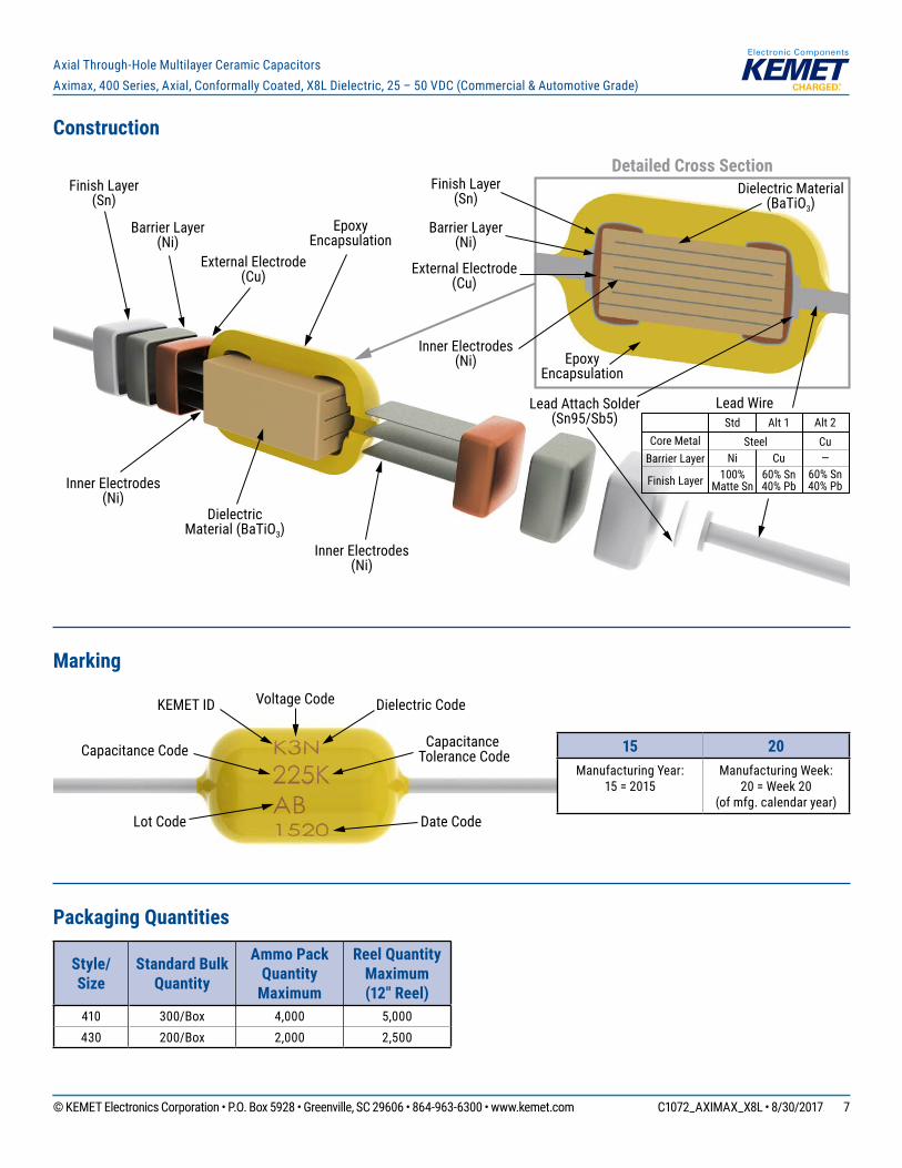
Construction
Dielectric Material (BaTiO3)
Detailed Cross Section
Inner Electrodes(Ni)
Barrier Layer(Ni)
External Electrode(Cu)
Finish Layer(Sn)
Epoxy Encapsulation
Inner Electrodes(Ni)
Finish Layer(Sn)
Barrier Layer(Ni)
External Electrode(Cu)
Epoxy Encapsulation
Inner Electrodes(Ni)
Dielectric Material (BaTiO3)
Lead Attach Solder(Sn95/Sb5)
Core MetalBarrier Layer
Finish Layer
Alt 1
Cu60% Sn40% Pb
Alt 2Cu—
60% Sn40% Pb
Lead Wire Std
Ni100%
Matte Sn
Steel
Marking
Voltage Code Dielectric CodeKEMET ID
Capacitance Tolerance CodeCapacitance Code
Lot Code Date Code
Packaging Quantities
Style/Size
Standard Bulk Quantity
Ammo Pack Quantity
Maximum
Reel Quantity Maximum(12" Reel)
410 300/Box 4,000 5,000430 200/Box 2,000 2,500
15 20Manufacturing Year:
15 = 2015Manufacturing Week:
20 = Week 20 (of mfg. calendar year)
© KEMET Electronics Corporation • P.O. Box 5928 • Greenville, SC 29606 • 864-963-6300 • www.kemet.com C1072_AXIMAX_X8L • 8/30/2017 8
Axial Through-Hole Multilayer Ceramic CapacitorsAximax, 400 Series, Axial, Conformally Coated, X8L Dielectric, 25 – 50 VDC (Commercial & Automotive Grade)
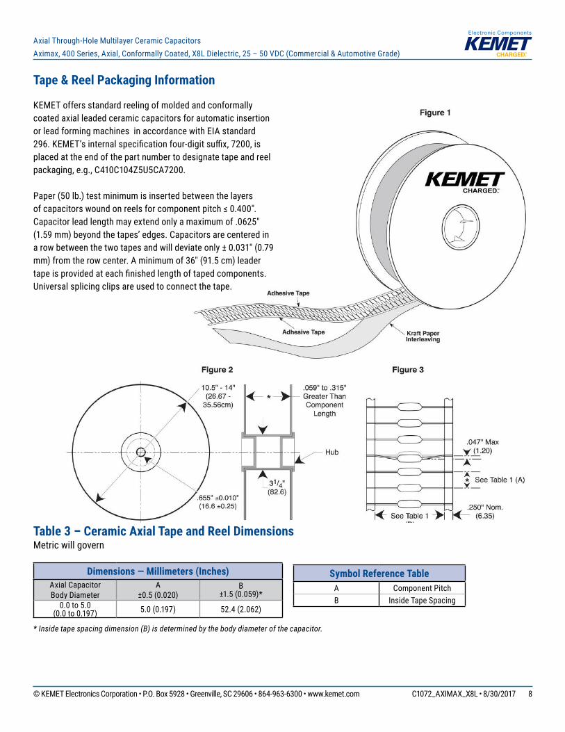
Symbol Reference TableA Component PitchB Inside Tape Spacing
Tape & Reel Packaging Information
KEMET offers standard reeling of molded and conformally coated axial leaded ceramic capacitors for automatic insertion or lead forming machines in accordance with EIA standard 296. KEMET’s internal specifi cation four-digit suffi x, 7200, is placed at the end of the part number to designate tape and reel packaging, e.g., C410C104Z5U5CA7200.
Paper (50 lb.) test minimum is inserted between the layers of capacitors wound on reels for component pitch ≤ 0.400". Capacitor lead length may extend only a maximum of .0625" (1.59 mm) beyond the tapes’ edges. Capacitors are centered in a row between the two tapes and will deviate only ± 0.031" (0.79 mm) from the row center. A minimum of 36" (91.5 cm) leader tape is provided at each fi nished length of taped components. Universal splicing clips are used to connect the tape.
Table 3 – Ceramic Axial Tape and Reel DimensionsMetric will govern
Dimensions — Millimeters (Inches)Axial Capacitor Body Diameter
A±0.5 (0.020)
B±1.5 (0.059)*
0.0 to 5.0 (0.0 to 0.197) 5.0 (0.197) 52.4 (2.062)
* Inside tape spacing dimension (B) is determined by the body diameter of the capacitor.

© KEMET Electronics Corporation • P.O. Box 5928 • Greenville, SC 29606 • 864-963-6300 • www.kemet.com C1072_AXIMAX_X8L • 8/30/2017 9
Axial Through-Hole Multilayer Ceramic CapacitorsAximax, 400 Series, Axial, Conformally Coated, X8L Dielectric, 25 – 50 VDC (Commercial & Automotive Grade)
KEMET Electronics Corporation Sales Offi ces
For a complete list of our global sales offi ces, please visit www.kemet.com/sales.
DisclaimerAll product specifi cations, statements, information and data (collectively, the “Information”) in this datasheet are subject to change. The customer is responsible for checking and verifying the extent to which the Information contained in this publication is applicable to an order at the time the order is placed.
All Information given herein is believed to be accurate and reliable, but it is presented without guarantee, warranty, or responsibility of any kind, expressed or implied.
Statements of suitability for certain applications are based on KEMET Electronics Corporation’s (“KEMET”) knowledge of typical operating conditions for such applications, but are not intended to constitute – and KEMET specifi cally disclaims – any warranty concerning suitability for a specifi c customer application or use. The Information is intended for use only by customers who have the requisite experience and capability to determine the correct products for their application. Any technical advice inferred from this Information or otherwise provided by KEMET with reference to the use of KEMET’s products is given gratis, and KEMET assumes no obligation or liability for the advice given or results obtained.
Although KEMET designs and manufactures its products to the most stringent quality and safety standards, given the current state of the art, isolated component failures may still occur. Accordingly, customer applications which require a high degree of reliability or safety should employ suitable designs or other safeguards (such as installation of protective circuitry or redundancies) in order to ensure that the failure of an electrical component does not result in a risk of personal injury or property damage.
Although all product–related warnings, cautions and notes must be observed, the customer should not assume that all safety measures are indicted or that other measures may not be required.
KEMET is a registered trademark of KEMET Electronics Corporation.