basic concepts and definitions - vidyarthiplus
TRANSCRIPT

Sri Vidya College of Engineering & Technology, Virudhunagar Course Material (Lecture Notes)
ME6301 Engineering Thermodynamics Unit I Page|1
BASIC CONCEPTS
AND
DEFINITIONS
Thermodynamics is the science of energy transfer which deals with the relations among heat,
work and properties of systems.
The name ‘thermodynamics’ is derived from the Greek words therme, meaning ‘heat’
and dynamis meaning power. Thus, thermodynamics is basically the study of heat and power.
1.1 Application Area of Thermodynamics
Energy transfer is present in almost all the engineering activities. Hence, the principles of
thermodynamics are playing vital role in designing all the engineering equipments such as internal
combustion engines, rockets, jet engines, thermal and nuclear power plants, refrigerators etc.
1.2 Statistical and Classical Thermodynamics
Statistical Thermodynamics is microscopic approach in which, the matter is assumed to be
made of numerous individual molecules. Hence, it can be regarded as a branch of statistical
mechanics dealing with the average behaviour of a large number of molecules.
Classical thermodynamics is macroscopic approach. Here, the matter is considered to be a
continuum without any concern to its atomic structure.
Consider a gas in a container. Pressure exerted at the wall of the container is the average force
per unit area due to the collision of the gas molecules on the wall surface. To determine this pressure,
we need not know the behaviour of individual molecules of the gas. This approach is macroscropic
approach. However, the results obtained from macroscopic and statistical study of matter.
1.3 Thermodynamic Systems and Surroundings
A Thermodynamic system is defined as a quantity of matter or a region in space whose
behaviour is being investigated.
Everything external to the system is defined as surroundings. In its usual context the term
‘surroundings’ is restricted to the regions in the immediate vicinity which has a detectable
influence on the system.
Boundary is the surface which separates the system from its surroundings. It may be fixed or
moving and real or imaginary.
www.Vidyarthiplus.com
www.Vidyarthiplus.com

Sri Vidya College of Engineering & Technology, Virudhunagar Course Material (Lecture Notes)
ME6301 Engineering Thermodynamics Unit I Page|2
Fig.1.1 Thermodynamic System, boundary, surroundings
1.3.1 Types of Thermodynamic Systems
There are three types of thermodynamic systems :
a) Closed System
b) Open System and
c) Isolated System
In closed system, attention is focused on a fixed mass. Energy in the form of heat and work (The
terms heat and work will be defined in the chapter 2.) can cross the boundary of the system. But there
is no mass flow across the boundary. Hence, the possibility of change in volume is always there in
the closed systems.
Fig.1.2 Closed system
In open system, both matter and energy can cross the boundary. Here, the behaviour of a fixed region
in space called control volume is investigated and hence, there is no change in volume. The surface
of the control volume is known as control surface.
Boundary System
Surroundings
Cylinder Piston
www.Vidyarthiplus.com
www.Vidyarthiplus.com

Sri Vidya College of Engineering & Technology, Virudhunagar Course Material (Lecture Notes)
ME6301 Engineering Thermodynamics Unit I Page|3
Fig.1.3 Open system
A system that exchanges neither energy nor matter with its surroundings is known as an isolated
system.
Fig.1.2 Isolated system
1.4 Thermodynamic Properties
In all thermodynamic problems energy transfer to or from the system is observed. To receive,
store and deliver energy a working substance is present within the system. The characteristics which
can be used to describe the condition of the system are known as properties.
Thermodynamic properties are classified into two categories : intensive and extensive.
Intensive properties are independent of quantity of matter or mass whereas extensive properties are
dependent on mass
Consider a vessel containing air. If a membrane is assumed to be introduced into the vessel, such that
it is divided into two equal parts. The properties remaining unchanged such as pressure and
temperature are intensive properties. Volume of air will be reduced to half of its initial value. Hence,
it is an extensive property.
1.5 Thermodynamic State and Equilibrium
Control
surface
Water in
Water out
Closed insulated
vessel
www.Vidyarthiplus.com
www.Vidyarthiplus.com

Sri Vidya College of Engineering & Technology, Virudhunagar Course Material (Lecture Notes)
ME6301 Engineering Thermodynamics Unit I Page|4
When a system does not undergo any change, all the properties have fixed values. This
condition is known as a thermodynamic state.
The word equilibrium means balance. An equilibrium state of a thermodynamic system is a
state that can not be changed without any interaction with its surroundings. The factors that cause a
change without any interactions with its surroundings are:
1. Pressure difference
2. Temperature difference
3. Chemical reaction
If a system is balanced in all respects, it is in a state of thermodynamic equilibrium. Balanced
in all respects means :
There should not be any temperature difference within the system, so that the system
is thermally balanced.
No pressure difference exists between any two points within the system (Neglecting
gravitational effects) and between the system and surroundings, so that it is
mechanically balanced.
No chemical reaction is taking place, so that it is chemically balanced.
If two phases are involved, mass of each phase remains constant so that phase
equilibrium is achieved.
Hence, for a system in a state of thermodynamic equilibrium, there is no change in any
macroscopic property.
1.6 Processes and Cycles
When a system is taken from one equilibrium state to another, the change is known as process.
The series of intermediate states through which a system passes during a process is called the path of
the process. If all these intermediate states are equilibrium states, the process is known as quasi
equilibrium or quasi-static process.
Consider a certain quantity of gas taken in a frictionless piston cylinder arrangement as shown
in Fig 1.5. The system is in thermodynamic equilibrium so that there is no unbalanced force acting
on piston.
Piston
Cylinder
thgieW thgieW
www.Vidyarthiplus.com
www.Vidyarthiplus.com

Sri Vidya College of Engineering & Technology, Virudhunagar Course Material (Lecture Notes)
ME6301 Engineering Thermodynamics Unit I Page|5
(a) (b)
Fig.1.5 Illustration for thermodynamic equilibrium
The moment the weight is removed from the piston, mechanical equilibrium does not exist and
as a result the piston is moved upward until mechanical equilibrium is restored again. Therefore the
actual process occurs only when equilibrium does not exist.
As shown in Fig.1.5.a, if the entire weight on the piston is removed at once, the deviation from
the equilibrium is high and the expansion is rapid. For such a process the intermediate states are not
equilibrium states and hence the process would be non-quasi-equilibrium.
If the weight is assumed to be made of a large number of small pieces as shown in Fig.1.5.b and
taken off one by one, the deviation from equilibrium is less. The process could be considered quasi-
equilibrium.
A thermodynamic system is said to undergo a cycle, if it is taken through a number of processes
such that, the final state of the last process is identical with the initial state of the first process in all
respects.For cycles net change in any property is zero.
1.7 Point and Path Functions
Thermodynamic functions are classified into two categories namely point and path functions.
Point functions are those for which the change depends on only the end states and not on the path
followed. Hence point functions are inexact differentials
Path functions are those for which the change depends not only on the end states but also on the path
followed. Hence path functions are exact differentials
In can be observed the change in any property during a process depends only on end states.
Therefore all the properties are point functions.
To demonstrate path and point functions, let us consider two stations A and B on a hill as
shown in the Fig.1.6. While moving from station A to station B, let the distance traveled and increase
in height from the mean sea level are observed. Distance traveled in path 1 is different from that in
path 2. Hence it may be regarded as path function. But the change in height is same in both path 1 and
path 2, therefore it is a point function.
1.8 State Postulate and Property Diagrams
As mentioned earlier, properties are meant for describing the state of a system. To fix a state,
all the properties need not be specified. If any two independent intensive properties are specified, rest
of the properties automatically assumes certain values.
This is known as state postulate.
www.Vidyarthiplus.com
www.Vidyarthiplus.com

Sri Vidya College of Engineering & Technology, Virudhunagar Course Material (Lecture Notes)
ME6301 Engineering Thermodynamics Unit I Page|6
Fig.1.7 property diagram of equilibrium and non equilibrium processes
Consider pressure and specific volume (Volume per unit mass) are the two independent,
intensive properties, describing the state of a compressible system. On a p-V diagram the state will
assume a point as represented in the Fig.1.7(a). Let the system be taken to another state such that all
the intermediate states are equilibrium states. The curve connecting the initial state and final state,
passing through all the intermediate states is indicating the path of the process. In non-quasi-
equilibrium process as the intermediate status can not be defined, the path is denoted by dashed line as
given in Fig.1.7(b)
Fig. 1.8 Thermodynamic cycle on a property diagram
Fig.1.8 indicates a system undergoing a cycle consisting of three quasi-equilibrium processes.
1.9 Temperature and Zeroth Law
Maxwell defined the temperature of a system as its Thermal state considered with reference to
its ability to communicate heat to other bodies.
1
V
p
2
1
p
2
1
V
2
3
p
www.Vidyarthiplus.com
www.Vidyarthiplus.com

Sri Vidya College of Engineering & Technology, Virudhunagar Course Material (Lecture Notes)
ME6301 Engineering Thermodynamics Unit I Page|7
When a hot body is brought into contact with a cold body, the hot body becomes cooler and the
cold body becomes hotter. After sufficient time, the temperature of both the bodies will be equal. At
that point, the two bodies are said to have reached thermal equilibrium.
Consider three bodies A, B and C. If the bodies A and B are in thermal equilibrium with C
when brought into contact separately, they are also in thermal equilibrium with each other. This
concept is known as zeroth law of thermodynamics.
Several properties of materials are found to be varying with temperature in a predictable way.
This variation is used to measure temperature. In mercury thermometers, expansion of mercury with
temperature is used for temperature measurement.
1.10 Temperature Scales
Freezing point of water known as ice point and boiling point of water known as steam point are
taken as the reference states for all types of temperature scales.
The various types as temperature scales in use are :
a) Celsius scale
b) Fahrenheit scale
c) Kelvin scale
d) Rankine scale
A
C
B
www.Vidyarthiplus.com
www.Vidyarthiplus.com

Sri Vidya College of Engineering & Technology, Virudhunagar Course Material (Lecture Notes)
ME6301 Engineering Thermodynamics Unit I Page|8
Reference
state
Celsius Kelvin Fahrenheit Rankine
Steam point 100 373 212 672
Ice point 0 273 32 492
Absolute Zero -273 0 460 0
1.11 Homogeneous and Heterogeneous Systems
Matter can exist in any one of the three phases namely solid, liquid and gas. A system
consisting of a single phase is known as homogeneous systems. If the matter exists in more than one
phase, the system is known as heterogeneous system.
Boiling point of water at 1 atm.
Steam point
Melting point/ Freezing point
Ice point
Absolute zero
www.Vidyarthiplus.com
www.Vidyarthiplus.com

Sri Vidya College of Engineering & Technology, Virudhunagar Course Material (Lecture Notes)
ME6301 Engineering Thermodynamics Unit I Page|9
1.12 Pure Substances
Substances of fixed chemical composition throughout are known as pure substances.
That is, pure substances have homogenous and invariable chemical composition irrespective of the
phase or phases in which they exist.
Example
a. Atmosphere air
b. Water
c. Nitrogen
d. Water-steam mixture
e. Product of combustion.
Though, mixture of water and steam is considered a pure substance, air and liquid air cannot be,
since, the chemical composition of liquid air differs from that of gaseous air.
1.13 The Ideal Gas
Based on the experimental work carried out by Boyle, Charles and Gay-Lussac, pressure,
temperature and specific volume of many gases at low pressure and moderate temperature are related
by the following equation.
pv = RT where R=
This equation is known as equation of state of an ideal gas. The term R is known as
characteristic gas constant and Ru universal gas constant. In SI unit R
u= 8.314 kJ/kgmol.K.
1.14 Concept of continuum
In microscopic approach the substance is assumed to be continuously distributed, ignoring the
space between the molecules. This is known as continuum hypothesis.
Since the matter is treated as continuous, the density at a point can be defined as
v
m
vv ,
lim
Where v’ is the smallest volume for which a definite value of the ratio exists. Below the
limiting value of v’ , the fluctuation in average density will be high and a definite value for the ratio
becomes impossible, with the mean free path*of the molecules approaching the order of magnitude of
the dimension of the vessel.
www.Vidyarthiplus.com
www.Vidyarthiplus.com

Sri Vidya College of Engineering & Technology, Virudhunagar Course Material (Lecture Notes)
ME6301 Engineering Thermodynamics Unit I Page|10
* mean free path is the distance traveled between two consecutive collisions of a molecule.
Exercises
1. Identify the type of the systems given below.
a) Reciprocating air compressor
b) Steam turbine in a steam power plant
c) Pressure cooker
d) Radiator of an automobile engine
e) A can of soft drink cooled inside the refrigerator
2. In ____________system control volume approach is employed.
3. Define a quasi-equilibrium process.
4. Define intensive and Extensive properties. Give examples.
5. What is the state postulate ?
6. What is zeroth law of thermodynamics ?
7. When does the concept of continuum become invalid ?
8. In which type of system neither mass nor energy is allowed to cross the boundary.
9. What is meant by thermodynamic equilibrium?
10. What is meant by a control surface?
11. What is meant by microscopic and macroscopic approach?
12. Universal gas constant = Characteristic Gas constant Molecular weight (T/F)
13. What is an open system? Give examples.
14. Define a closed system. Give example
www.Vidyarthiplus.com
www.Vidyarthiplus.com
Sri Vidya College of Engineering & Technology, Virudhunagar Course Material (Lecture Notes)
ME6301 Engineering Thermodynamics Unit I Page|11
Chapter 2
WORK AND HEAT
In the previous chapter, the different thermodynamic systems and their characteristics were
discussed. To undergo a change of state, the system has to interact with its surroundings. Work and
heat transfers across the boundaries cause these changes. In this chapter various forms of work and
modes of heat transfers are discussed.
2.1 Work as Defined in Mechanics
www.Vidyarthiplus.com
www.Vidyarthiplus.com

Sri Vidya College of Engineering & Technology, Virudhunagar Course Material (Lecture Notes)
ME6301 Engineering Thermodynamics Unit I Page|12
work is done when the point of application of a force moves in the direction of the force. The
product of the force and the distance moved in the direction of the force is equal to the amount of the
work done.
This simple definition of work confines only to the area of mechanics and can not be extended
to the more complex problems in thermodynamics. Hence a new definition should be introduced to
cover mechanical as well as the other forms of work.
2.2 The Thermodynamic Definition of Work
Positive work is done by a system, during a given process, when sole effect external to the
system could be reduced to the lifting of a mass.
Consider a gas expanding in a piston cylinder arrangement as given in Figure 2.1. Here no
mass is actually lifted against gravity. But if the existing surroundings is fitted with an arrangement
as given in the Figure 2.2, there is a possibility of lifting the mass. Hence work is said to be done by
the system.
While exploring the possibility of lifting a mass the effects that are external to the system alone
must be taken into account. For example, a lift with a person and a suitcase is considered as a system.
If the person lifts the suitcase, it should not be taken into account, because this event occurs within the
system.
www.Vidyarthiplus.com
www.Vidyarthiplus.com
Sri Vidya College of Engineering & Technology, Virudhunagar Course Material (Lecture Notes)
ME6301 Engineering Thermodynamics Unit I Page|13
2.3 Units of Work and Power
In the international system (SI), the unit of force is Newton (N) and that of distance is metre
(m). Hence the unit of work is Nm which is also given a special name Joule. In most of the
applications large quantity of work is involved. Therefore kJ is commonly used.
Rate of doing work is known as power. Hence its unit is Nm/S or J/S which is again given a
special name Watts(W).
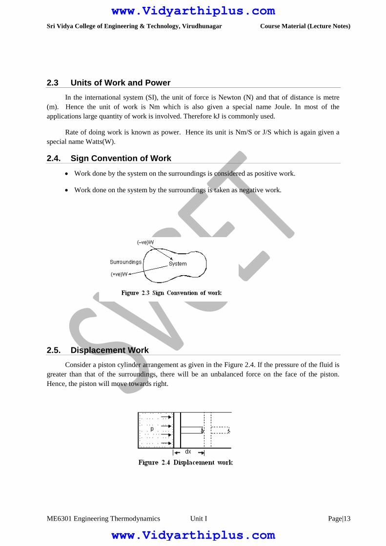
2.4. Sign Convention of Work
Work done by the system on the surroundings is considered as positive work.
Work done on the system by the surroundings is taken as negative work.
2.5. Displacement Work
Consider a piston cylinder arrangement as given in the Figure 2.4. If the pressure of the fluid is
greater than that of the surroundings, there will be an unbalanced force on the face of the piston.
Hence, the piston will move towards right.
www.Vidyarthiplus.com
www.Vidyarthiplus.com

Sri Vidya College of Engineering & Technology, Virudhunagar Course Material (Lecture Notes)
ME6301 Engineering Thermodynamics Unit I Page|14
Force acting on the piston Pressure Area
pA
Work done Force distance
pA dx
pdV
where dV - change in volume.
This work is known as displacement work or pdV work corresponding to the elemental
displacement dx. To obtain the total work done in a process, this elemental work must be added from
the initial state to the final state. Mathematically, .
2.6 Evaluation of Displacement Work
2.6.1. Constant Pressure Process
Figure 2.5 shows a piston cylinder arrangement containing a fluid. Let the fluid expands such
that the pressure of the fluid remains constant throughout the process. Figure 2.6 shows the process in
a p-V diagram.
The mathematical expression for displacement work can be obtained as follows:
p(V2 – V
1) ...(2.1)
This expression shows that the area under a curve in a p-V diagram gives work done in the
process.
2.6.2. Constant volume process
www.Vidyarthiplus.com
www.Vidyarthiplus.com

Sri Vidya College of Engineering & Technology, Virudhunagar Course Material (Lecture Notes)
ME6301 Engineering Thermodynamics Unit I Page|15
Consider a gas contained in a rigid vessel being heated. Since there is no change in volume, the
displacement work .
2.6.3 Hyperbolic process
Let the product of pressure and volume remains constant at all the intermediate states of a
process. In the p-V diagram it will be a hyperbola as given in Figure 2.7.
1W
2 =
2
1
pdV
= 2
1
CdV where C=pV
= C 2
1
1dV
V
= C ln (V2/V1)
1w
2 = p
1V
1ln(V2/V1) (or) p
2V
2ln (V2/V1) ...(2.2)
For Ideal gases when temperature remains constant, pV will be constant i.e., isothermal process
are hyperbolic processes for an ideal gas.
2.6.4 Polytropic Process
Any process can be represented by the general form pVn constant. Based on the valve of n,
the process differs as given below;For other values of n, the process is known as polytropic process.
Figure 2.8 shows the polytropic process of various possible polytropic index ‘n’ on p-V coordinates.
Expression for displacements work for a polytropic process can be obtained as follows :
www.Vidyarthiplus.com
www.Vidyarthiplus.com

Sri Vidya College of Engineering & Technology, Virudhunagar Course Material (Lecture Notes)
ME6301 Engineering Thermodynamics Unit I Page|16
1W
2
2
1
pdV
2
1
dVV
Cn
where C = pVn
C
2
1
dVV n
C
2
1
1
1
n
V n
2
1
1
1
1
2
1
n
CVCVnn
1
1
111
1
222
n
VVpVVpnnnn
since C p1V
1
n p2Vn
2
1
1
1122
n
VpVp ...(2.3)
2.7 Work is a Path Function
Consider a working substance initially occupying 0.2 m3 at 1 bar as represented by state 1 in the
Figure 2.9. Let the system changes its state such that the final volume is 0.05m3 and pressure 2 bar.
The change of state may occur along the paths 1A2,1B2 or 1C2. As mentioned earlier, area under the
curve representing the process in a p-V diagram gives the work done in the process. Comparing the
area under the paths 1A2, 1B2 and 1C2, it is clear that the work done in these paths are different.
Hence it can be concluded that the amount of work done is not only a function of the end states of a
process, but also the path followed between the states. Therefore work is a path function.
2.8 Additivity of Work Over Processes
If a system is taken through two or more number of processes, the total work done is the sum of
work done in the individual processes.
Let a system executes three processes as shown in Figure 2.10. The total work done,
1W
4
1W
2
2W
3
3W
4 ...(2.4)
2.11 Heat
www.Vidyarthiplus.com
www.Vidyarthiplus.com

Sri Vidya College of Engineering & Technology, Virudhunagar Course Material (Lecture Notes)
ME6301 Engineering Thermodynamics Unit I Page|17
Heat is the interaction between systems which occurs by virtue of their temperature difference
when they communicate.
If a system, at a given temperature is brought in contact with another system (or surroundings)
at a lower temperature, it can be observed that heat is transferred from the system at the higher
temperature to the system at lower temperature. This heat transfer occurs solely because of the
temperature difference between the two systems. Another important aspect of the definition of heat is
that a body never contains heat. Rather, heat can be identified only as it crosses the boundary. Similar
to work, heat is also a form of energy transfer occurring at the boundary of the system and is a path
function.
2.12 Sign Convention of Heat
Heat given into a system is positive
Heat coming out of the system is negative
Fig. 2.8 Sign convention of work
2.13 Modes of Heat Exchange
Conduction, convection and radiation are the three possible modes of heat transfer between
systems and between system and its surroundings.
Conduction occurs without bulk movement of molecules. Energy transfer in conduction is due
to lattice vibration and free electron movement. It is the predominant mode of heat transfer in solids.
Convection occurs with bulk movement of molecules and therefore, occurs in gases and liquids.
If the bulk movement or flow is due to an external device, it is known as forced convection. In the
absence of an external device the flow is due to the difference in density caused by the temperature
difference. This mode is known as natural convection.
www.Vidyarthiplus.com
www.Vidyarthiplus.com

Sri Vidya College of Engineering & Technology, Virudhunagar Course Material (Lecture Notes)
ME6301 Engineering Thermodynamics Unit I Page|18
Bodies separated by a distance may exchange heat in the form of electromagnetic waves
without the participation of the intervening medium. It is known as radiation. It is generally a surface
phenomenon. Sometimes as in the case of gas mixtures containing carbon dioxide and water vapour it
is a volume phenomenon.
2.14 Sensible and Latent Heat
It is known that a substance can exists in three phases namely solid, liquid and gas. When a
substance is heated or cooled temperature of the substance increases or decreases respectively unless
there is any phase change. Quantity of heat added or removed to change the temperature by unit
degree is known as specific heat. For solids and liquids same quantity of heat is required to cause unit
degree rise for both constant pressure heating as well as constant volume heating as they are
incompressible. But for gases there is appreciable difference in the quantity of heat required to cause
unit difference in temperature between constant volume and constant pressure processes. Accordingly,
they are known as specific heat at constant volume (CV) and specific heat at constant pressure (C
P).
Thus to increase the temperature of m kg of the given substance by T degree, amount of heat
required is given by
Q mCVT at Constant Volume ...(2.5)
Q1 mC
PT at Constant Pressure …(2.6)
If a certain single component system is undergoing phase change at constant pressure,
temperature of the system remains constant during heating or cooling. Quantity of heat removed or
added to cause the change of phase of unit mass of the substance is known as latent heat. For example
latent heat of fusion of water is the amount of heat to be removed to solidify 1 kg of water into 1 kg of
ice at a given temperature.
Let us consider a process of converting 1 kg of ice at 30C to system to steam at 250C at
atmospheric pressure. We know that ice melts at 0C and water evaporates at 100C at atmospheric
pressure.
For a constant rate of heating, if temperature at different instants are plotted we will get a graph
as shown in Figure 2.9.
www.Vidyarthiplus.com
www.Vidyarthiplus.com

Sri Vidya College of Engineering & Technology, Virudhunagar Course Material (Lecture Notes)
ME6301 Engineering Thermodynamics Unit I Page|19
Figure 2.9 Illustration for sensible and latent heat
The total heat required can be obtained as follows:
Q Qab Q
bc Q
cd Q
de Q
ef ...(2.7)
Qab mC
ice (t
b t
c) ...(2.8)
Qbc Latent heat of melting of ice at 0C
Qcd mC
water (t
d t
c) ...(2.9)
Qde Latent heat of evaporation of water at 100C
Qef mC
PSteam (t
f - t
e) ...(2.10)
Where Cice Specific heat of ice
Cwater
Specific heat of water
CPSteam
Specific heat of steam at constant pressure
2.15 Reversible Adiabatic Process
A reversible process during which, the system and the surroundings do not exchange any heat
across the boundary is known as reversible adiabatic process. For such a process, pressure and volume
variation is governed by the law :
pV constant . ..(2.11)
Where
Cp is the specific heat at constant pressure
CV is the specific heat at constant volume
Detailed discussion on these specific heats is presented in the next chapter.
A wall which does not permit the heat flow across it is known as adiabatic wall, whereas the
wall that permits the heat is known as diathermic wall. In an adiabatic process the only possible
energy interaction across the boundary of the system is work transfer to or from the system.
Displacement work involved in a reversible adiabatic process can be expressed as
W =
1
1122
VpVp ...(2.12)
2.16 Comparison between work and heat
Both heat and work are boundary phenomena, that is, they occur only at the
boundary.
www.Vidyarthiplus.com
www.Vidyarthiplus.com

Sri Vidya College of Engineering & Technology, Virudhunagar Course Material (Lecture Notes)
ME6301 Engineering Thermodynamics Unit I Page|20
The interaction due to the temperature difference is heat and all other
interactions are to be taken as work.
Both work and heat are path functions, that is, they are inexact differentials.
Exercises
1. Name the forms of energy transfer across the boundary of a thermodynamic system.
2. State the thermodynamics definition of work.
3. Displacement work is not applicable to _____________ systems.
4. The polytropic index n of process can be represented by
a) n b) n c) n
choose the right answer.
5. What are point and path functions? Give examples.
6. What is meant by displacement work?
7. What is meant by an indicator diagram?
8. Define mean effective pressure.
9. What are the modes of heat transfer?
10. A certain fluid expands in a quasi-static process from 0.1 m3 to 0.8 m3 at a constant pressure of
1000 kPa. Find the work done. [700 kJ]
11. Zeroth law of thermodynamics is the basis of _______________________
a) Temperature measurement c) Heat measurement
b) Pressure measurement d) Internal energy
e) Enthalpy
Choose the correct answer
12. Mass remains constant for a closed system (T / F)
www.Vidyarthiplus.com
www.Vidyarthiplus.com

Sri Vidya College of Engineering & Technology, Virudhunagar Course Material (Lecture Notes)
ME6301 Engineering Thermodynamics Unit I Page|21
13. What are the similarities between work and heat?
14. Calculate the work required to lift a 25 kg body from an elevation of 200 m above
mean sea level to an elevation of 300 m in 2 minutes.
[24.525 kJ]
15. What is the work done in compressing a spring of stiffness 500 N/cm by 2 cm?
[1 kJ]
16. An electric water with a resistance of 50 Ohms heater is connected across a
power supply of 240 Volt for a period of 1 hour.
a) Determine the work done by the power source on the heater.
b) How many units of electricity are consumed?
[5184 kJ; 1.44 k Whr]
17. A gas is contained in a piston cylinder arrangement as given in the Figure 2.28.Initial volume of
the gas is 0.5 m3. It is compressed from 1 bar to 10 bar such that the temperature remains
constant. Find the final volume and work done.
[0.05 m3 ;115.13 kJ]
18. Air expands from 0.1 m3 to 0.23 m3 at a constant temperature of 50oC. Calculate the work done
per kg of air. Rair 0.287 kJ/kgK.
[77.2 kJ]
19. Oxygen contained in a cylinder fitted with a piston expands in a quasistatic process according
to the law pV1.5 constant. The initial pressure, temperature and volume are 5 bar, 300 k and
0.05 m3. After expansion, the pressure is 2 bar.
Find the following :
a. Final volume
b. Final temperature
c. Work done
[0.0921 m3 ; 221 K ; 13.16 kJ]
20. Air is compressed adiabatically from 0.92 m3 to 0.29 m3 in a piston cylinder arrangement.
Taking its initial pressure and temperature as 103 kPa and 300 k respectively, find the work
done. Also find the final temperature.
[139.04 kJ ; 476 K]
21. A spherical balloon has a diameter of 25 cm and contains air at a pressure of 150 kPa. The
diameter of the balloon increases to 30 cm because of heating, and during this process, the
www.Vidyarthiplus.com
www.Vidyarthiplus.com

Sri Vidya College of Engineering & Technology, Virudhunagar Course Material (Lecture Notes)
ME6301 Engineering Thermodynamics Unit I Page|22
pressure is proportional to the diameter. Calculate the work done on the gas assuming
reversible work interaction.
[0.989 kJ]
22. A bicycle pump has a total stroke of 25 cm and is used to pump air into a tyre against a pressure
of 3.5 bar. Calculate the length stroke necessary before air enters the tyre when the piston is
pushed in
a) rapidly
b) slowly
Assume atmospheric pressure is 1 bar.
[17.0 cm ; 17.9 cm]
23. A mass of air occupying 0.5 m3 at 2 bar and 200oC is compressed reversibly and adiabatically to
5 bar and then it undergoes isobaric expansion so that it gives out 45 kJ of work. If the system
is to be brought back to its initial state what should be the polytropic index ? calculate the
network interaction of this cycle. Sketch the cycle on a p-V diagram. Also compute the power
developed if the number of cycles executed per minute is 300.
[2.57 ; 17.8 kJ ; 88.9 kW]
24. It is required to lift five people on an elevator through a height of 100 m. The work required is
found to be 341.2 kJ and the gravitational acceleration is 9.75 m/s2. Determine the average mass
per person.
[69.95 kg]
25. What is the work required to accelerate a vehicle of mass 500 kg from rest to a velocity of 60
kmph.
[69.44 kJ]
26. The indicator card of an 8 cm bore, 10 cm stroke water pump is in the shape of a rectangle of
dimension 2 10 cm. The indicator spring constant is 22 MPa/m.
a) Find the mean effective pressure.
b) If the cycle is repeated once in every second, what is the power required by the pump?
[440 kPa ; 0.22 kW]
27. A quantity of a substance in a closed vessel is undergoing a reversible process in
such a way that the pressure is proportional to the square roof of volume from 1 m3
to 2m3. The initial pressure is 100 KPa. Compute the work done.
[2.33 kJ]
28. A cylinder of 8 cm internal diameter is fitted with a piston loaded by a coil spring
of stiffness 140 N/cm of compression. The cylinder contains 0.0005m3 of air at
www.Vidyarthiplus.com
www.Vidyarthiplus.com

Sri Vidya College of Engineering & Technology, Virudhunagar Course Material (Lecture Notes)
ME6301 Engineering Thermodynamics Unit I Page|23
15C and 3 bar. Find the work done when the piston moves by 4 cm as the gas
expands.
[ 7.11 J]
29. Carbondioxide is taken in a piston cylinder arrangement such that it occupies a
volume of 1m3 at 1 bar and 27C. It has to be compressed to 0.2 m3 such that the
temperature remains constant during compression. Compute the workdone and
final pressure.
[-160.94 kJ; 500 kPa]
30. 5 kg of oxygen initially at 10 bar, 370 K is undergoing expansion to 1 bar. If the
final temperature is 300K. Determine the following:
a) Initial volume
b) Final volume
c) Polytropic index
d) Work done
Take the molecular weight of oxygen as 32.
[0.48m3 ; 3.897m3 ; 1.1 ; 903 kJ]
31. A rigid container of volume 0.4 m3 is filled with oxygen until the pressure reaches
1200 kPa. It is then cooled so that the pressure reduces to 900 kPa. How much
work is performed ? Draw a p-V diagram for the process.
[0 kJ]
32. A paddle wheel supplies work to a system at the rate of 80 W. During a period of
1 minute the system expands from 0.03 m3 to 0.08 m3 against a constant pressure of
500 kPa. Find the net work interaction during this period of 1 minute.
Ans : [20.2 kJ]
33. 1 Kg of air undergoes expansion from 800 kPa, 300 K to 120 kPa in such a way
that p(v + 0.2) = Constant, where p is the pressure in kPa and v is the specific
volume in m3/Kg. Find the work done in the process.
Ans : [466.88 kJ]
www.Vidyarthiplus.com
www.Vidyarthiplus.com

Sri Vidya College of Engineering & Technology, Virudhunagar Course Material (Lecture Notes)
ME6301 Engineering Thermodynamics Unit I Page|24
Chapter 3
THE FIRST LAW
OF THERMODYNAMICS
Energy interactions between a system and its surroundings across the boundary in the form of
heat and work have been discussed separately in the previous chapter.
So far, no attempt has been made to relate these interactions between themselves and with the energy
content of the system.
First law of thermodynamics, often called as law of conservation of energy, relating work,
heat, and energy content of the system will be discussed in detail in this chapter.
3.1 First Law of Thermodynamics
In its more general form, the first law may be stated as follows
“When energy is either transferred or transformed, the final total energy present in all forms
must precisely equal the original total energy”.
It is based on the experimental observations and can not be proved mathematically. All the
observations made so far, confirm the correctness of this law.
3.2 First Law of Thermodynamics for a Closed System
Undergoing a Process
First law can be written for a closed system in an equation form as
systemtheofcontent
energytheinChange
systemthe
leftEnergy
systemthentoi
enteredEnergy
For a system of constant mass, energy can enter or leave the system only in two forms namely
work and heat.
Let a closed system of initial energy E1 receives Q units of net heat and gives out W units of
work during a process. If E2 is energy content at the end of the process as given in Figure 3.1,
applying first law we get
www.Vidyarthiplus.com
www.Vidyarthiplus.com

Sri Vidya College of Engineering & Technology, Virudhunagar Course Material (Lecture Notes)
ME6301 Engineering Thermodynamics Unit I Page|25
Q W (E2 E
1) ...(3.1)
Where the total energy content
Internal Energy + Kinetic energy + Potential energy
U + cg
mC 2
2
1 + mgz
The term internal energy usually denoted by the letter U is the energy due to such factors as
electron spin and vibrations, molecular motion and chemical bond.
Kinetic energy term is due to the system movement with a velocity C. For stationary systems
this term will be zero. The term gc is a constant of value 1 in SI unit. It will be dropped here after
since SI unit is followed throughout the book.
Potential energy term is due to the location of the system in the gravitational field. It remains
constant for a stationary system. The unit of energy in SI is kJ.
3.3 The Thermodynamic Property Enthalpy
Consider a stationary system of fixed mass undergoing a quasi-equilibrium constant pressure
process
Applying first law
Q12
1W
2 E
2 E
1
where E2 E
1 (U
2 U
1) + m(C2
2 C
1
2) + mg(Z2 Z
1)
U2 U
1 since it is a stationary system.
also 1W
2 p(V
2 V
1)
p2V
2 p
1V
1
www.Vidyarthiplus.com
www.Vidyarthiplus.com

Sri Vidya College of Engineering & Technology, Virudhunagar Course Material (Lecture Notes)
ME6301 Engineering Thermodynamics Unit I Page|26
Q12 (p
2V
2 p
1V
1) + (U
2 U
1)
Q12
(U2 + p
2V
2) (U
1 + p
1V
1)
The terms within brackets are all properties depending on the end states. This combination of
properties may be regarded as a single property known as enthalpy. It is usually denoted by the letter
H.
ie H U + pV ...(3.3a)
(or) h u + pv ...(3.3b)
Where h is specific enthalpy in kJ/kg
u is specific internal energy in kJ/kg and
v is specific volume in m3/kg
3.4 Flow Energy
Flow energy is defined as the energy required to move a mass into the a control volume against
a pressure. Consider a mass of volume V entering into a control volume as given in the Figure 3.2
against a pressure p.
The Flow energy Work done in moving the mass
Force distance
www.Vidyarthiplus.com
www.Vidyarthiplus.com

Sri Vidya College of Engineering & Technology, Virudhunagar Course Material (Lecture Notes)
ME6301 Engineering Thermodynamics Unit I Page|27
pA dx
p (Adx)
pV ...(3.4)
Therefore, Enthalpy Internal energy + Flow energy
3.5 First Law of Thermodynamics for a Control Volume
Mass simultaneously entering and leaving the system is a very common phenomenon in most of
the engineering applications. Control volume concept is applied to these devices by assuming suitable
control surfaces.
To analyze these control volume problems, conservation of mass and energy concepts are to be
simultaneously considered.
Energy may cross the control surface not only in the form of heat and work but also by total
energy associated with the mass crossing the boundaries. Hence apart from kinetic, potential and
internal energies, flow energy should also be taken into account.
Conservation of mass
volumecontrol
theofcontentmass
theinchangeNet
volumecontrol
theleaving
massTotal
volumecontrol
theentering
massTotal
Conservation of energy
volumecontrol
theofcontent
theenrgyin
changeNet
volumecontrolthe
leavingmass
thewithassociated
energyTotal
volumecontrolthe
enteringmass
thewithassociated
energyTotal
workand
heatofform
theinboundary
thecrossingenergyNet
...(3.5)
.
Q
.
W
.
inm.
outm
Control
Volume
www.Vidyarthiplus.com
www.Vidyarthiplus.com

Sri Vidya College of Engineering & Technology, Virudhunagar Course Material (Lecture Notes)
ME6301 Engineering Thermodynamics Unit I Page|28
Figure 3.3 First Law of Thermodynamics Applied to a control Volume
As a rate equation, it becomes
CV
out
out
in
in EZgC
hmZgC
hmWQ
22
22
...(3.6)
3.6 The Steady-state Flow Process
When a flow process is satisfying the following conditions, it is known as a steady flow
process.
1. The mass and energy content of the control volume remains constant with time.
2. The state and energy of the fluid at inlet, at the exit and at every point within the control
volume are time independent.
3. The rate of energy transfer in the form of work and heat across the control surface is
constant with time.
Therefore for a steady flow process
...(3.7)
...(3.7)
also
...(3.8)
...(3.9)
Control Surface
outin mm
0 CVE
022
22
Zg
ChmZg
ChmWQ
out
out
in
in
www.Vidyarthiplus.com
www.Vidyarthiplus.com

Sri Vidya College of Engineering & Technology, Virudhunagar Course Material (Lecture Notes)
ME6301 Engineering Thermodynamics Unit I Page|29
For problem of single inlet stream and single outlet stream
gZZ
CChhmWQ 12
2
1
2
212
2)( ...(3.10)
This equation is commonly known as steady flow energy equation (SFEE).
3.7 Application of SFEE
SFEE governs the working of a large number of components used in many engineering
practices. In this section a brief analysis of such components working under steady flow conditions
are given and the respective governing equations are obtained.
3.7.1. Turbines
Turbines are devices used in hydraulic, steam and gas turbine power plants. As the fluid
passesthrough the turbine, work is done on the blades of the turbine which are attached to a shaft.
Due to the work given to the blades, the turbine shaft rotates producing work.
Figure 3.4 Schematic Representation of a Turbine
General Assumptions
1. Changes in kinetic energy of the fluid are negligible
Mass entering
Mass leaving
Shaft work
Control
Surface
www.Vidyarthiplus.com
www.Vidyarthiplus.com
Sri Vidya College of Engineering & Technology, Virudhunagar Course Material (Lecture Notes)
ME6301 Engineering Thermodynamics Unit I Page|30
2. Changes in potential energy of the fluid are negligible.
)( 12 hhmWQ ...(3.11)
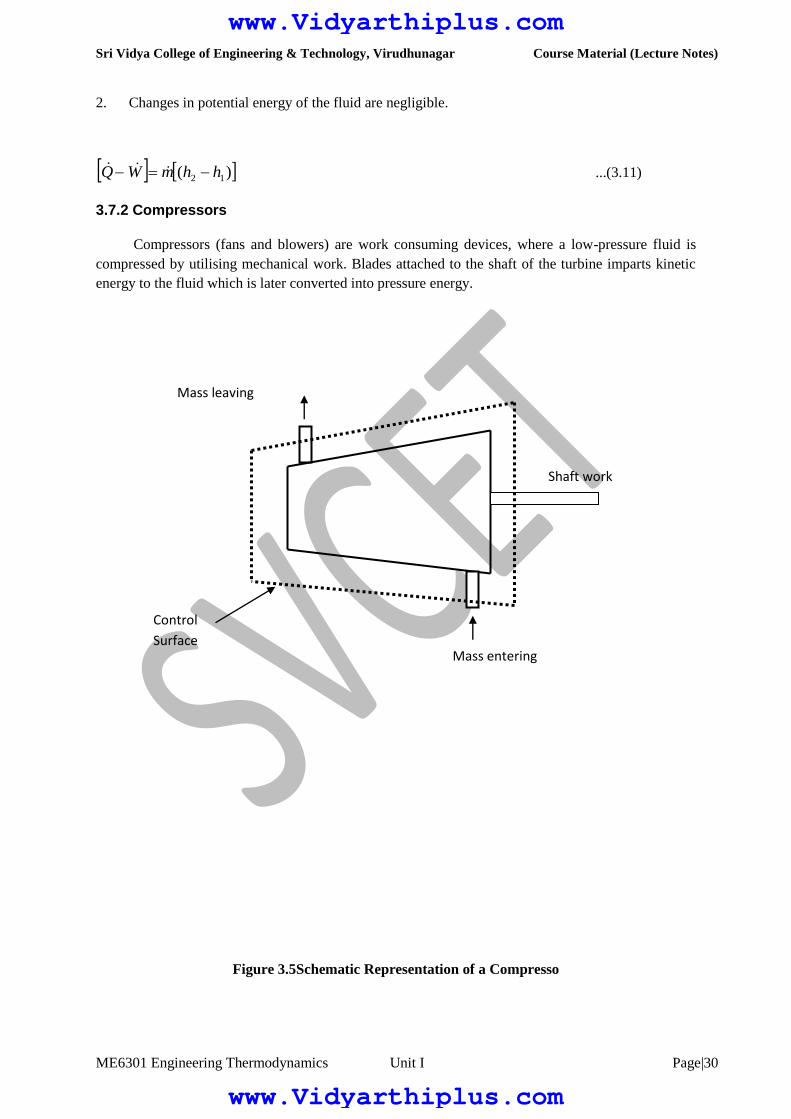
3.7.2 Compressors
Compressors (fans and blowers) are work consuming devices, where a low-pressure fluid is
compressed by utilising mechanical work. Blades attached to the shaft of the turbine imparts kinetic
energy to the fluid which is later converted into pressure energy.
Figure 3.5Schematic Representation of a Compresso
Mass entering
Mass leaving
Shaft work
Control
Surface
www.Vidyarthiplus.com
www.Vidyarthiplus.com

Sri Vidya College of Engineering & Technology, Virudhunagar Course Material (Lecture Notes)
ME6301 Engineering Thermodynamics Unit I Page|31
General Assumptions
1. Changes in the kinetic energy of the fluid are negligible
2. Changes in the potential energy of the fluid are negligible
Governing Equation
Applying the above equations SFEE becomes
)( 12 hhmWQ ...(3.12)
3.7.3 Pumps
Similar to compressors pumps are also work consuming devices. But pumps handle
incompressible fluids, whereas compressors deal with compressible fluids.
General Assumptions
1. No heat energy is gained or lost by the fluids;
2. Changes in kinetic energy of the fluid are negligible.
Governing Equation
www.Vidyarthiplus.com
www.Vidyarthiplus.com

Sri Vidya College of Engineering & Technology, Virudhunagar Course Material (Lecture Notes)
ME6301 Engineering Thermodynamics Unit I Page|32
gZZhhmW 1212 )( ...(3.13)
As the fluid passes through a pump, enthalpy of the fluid increases, (internal energy of the fluid
remains constant) due to the increase in pv (flow energy). Increase in potential energy of fluid is the
most important change found in almost all pump applications.
3.7.4 Nozzles
Nozzles are devices which increase the velocity of a fluid at the expense of pressure. A typical
nozzle used for fluid flow at subsonic* speeds is shown in Figure 3.7.
General Assumptions
1. In nozzles fluids flow at a speed which is high enough to neglect heat lost or gained
as it crosses the entire length of the nozzle. Therefore, flow through nozzles can be
regarded as adiabatic. That is 0.
2. There is no shaft or any other form of work transfer to the fluid or from the fluid; that
is 0.
3. Changes in the potential energy of the fluid are negligible.
Governing Equation
In Out
Control Surface
www.Vidyarthiplus.com
www.Vidyarthiplus.com

Sri Vidya College of Engineering & Technology, Virudhunagar Course Material (Lecture Notes)
ME6301 Engineering Thermodynamics Unit I Page|33
)(2
02
)(
21
2
1
2
2
2
1
2
212
hhCC
CChh
3.7.5 Diffusers
Diffusers are (reverse of nozzles) devices which increase the pressure of a fluid stream by
reducing its kinetic energy.
General Assumptions
Similar to nozzles, the following assumptions hold good for diffusers.
1. Heat lost or gained as it crosses the entire length of the nozzle. Therefore, flow through nozzles
can be regarded as adiabatic. That is 0Q
2. There is no shaft or any other form of work transfer to the fluid or from the fluid; that
is 0.
3. Changes in the potential energy of the fluid are negligible
Governing Equation
...(3.14)
3.7.6 Heat Exchangers
Devices in which heat is transferred from a hot fluid stream to a cold fluid stream are known as
heat exchangers.
2)(
02
)(
2
2
2
112
2
1
2
212
CChh
CChh
www.Vidyarthiplus.com
www.Vidyarthiplus.com

Sri Vidya College of Engineering & Technology, Virudhunagar Course Material (Lecture Notes)
ME6301 Engineering Thermodynamics Unit I Page|34
Hot fluid out
Cold fluid in
cold
fluid out
Hot fluid in
General Assumptions
1. Heat lost by the hot fluid is equal to the heat gained by the cold fluid.
2. No work transfer across the
control volume.
3. Changes
in kinetic and potential energies
of both the streams are
negligible.
Governing Equation
For both hot and cold streams
As per the assumption,
coldhot QQ
The negative sign in the LHS is to represent that heat is going out of the system.
)()( 1221 hhmhhm ch ...(3.15)
3.7.7 Throttling
A throttling process occurs when a fluid flowing in a line suddenly encounters a restriction in the flow
passage. It may be
a plate with a small hole as shown in Figure 3.10 (a)
a valve partially closed as shown in Figure 3.10 (b)
a capillary tube which is normally found in a refrigerator as shown in Figure 3.10 (c)
a porous plug as shown in
Figure 3.10 (d)
)( 12 hhmQ
www.Vidyarthiplus.com
www.Vidyarthiplus.com

Sri Vidya College of Engineering & Technology, Virudhunagar Course Material (Lecture Notes)
ME6301 Engineering Thermodynamics Unit I Page|35
General assumptions
1. No heat energy is
gained or lost by the fluid; ie., 0
www.Vidyarthiplus.com
www.Vidyarthiplus.com

Sri Vidya College of Engineering & Technology, Virudhunagar Course Material (Lecture Notes)
ME6301 Engineering Thermodynamics Unit I Page|36
1
2
Path A
Path B
p
V
2. There is typically some increase in velocity in a throttle, but both inlet and exit
kinetic energies are usually small enough to be neglected.
3. There is no means for doing work; ie., 0.
4. Changes in potential energy of the fluid is negligible.
Governing Equation
h2 h
1 ...(3.16)
Therefore, throttling is an isenthalpic process.
3.8 First Law for a Cyclic Process
In a cyclic process the system is taken through a series of processes and finally returned to its
original state. The end state of a cyclic process is identical with the state of the system at the
beginning of the cycle. This is possible if the energy level at the beginning and end of the cyclic
process are also the same. In other words, the net energy change in a cyclic process is zero.
Figure 3.11 First Law for a Cyclic Process
Consider a system undergoing a cycle consisting of two processes A & B as shown in Figure
3.11 Net energy change
EA
+EB 0 ..(3.17)
(QA W
A) + (Q
B W
B) 0 ...(3.18)
www.Vidyarthiplus.com
www.Vidyarthiplus.com

Sri Vidya College of Engineering & Technology, Virudhunagar Course Material (Lecture Notes)
ME6301 Engineering Thermodynamics Unit I Page|37
1
2
Path A
Path B
Path C
p
V
ie QA Q
B W
A W
B ...(3.19)
(or) dWdQ ...(3.20)
Hence for a cyclic process algebraic sum of heat tranfers is equal to the algebraic sum of work
transfer.
This was first proved by Joule, based on the experiments he conducted between 1843 and 1858,
that were the first quantitative analysis of thermodynamic systems.
3.9 Energy is a property of a system
Consider a system undergoing a process from state1 to state2 along path A as shown in Figure
3.12. Let the system be taken back to the initial state 1 along two possible paths B and C. Process A,
combined separately with process B and C forms two possible cycles.
Figure 3.12Illustration to show that energy is property
Cycle 1A2B1
QA Q
B [W
A W
B]
QA W
A[Q
B W
B]
EA E
B ...(3.21)
www.Vidyarthiplus.com
www.Vidyarthiplus.com

Sri Vidya College of Engineering & Technology, Virudhunagar Course Material (Lecture Notes)
ME6301 Engineering Thermodynamics Unit I Page|38
Cycle 1A2C1
QA Q
C [W
A W
C]
QA W
A[Q
C W
C]
EAE
C ...(3.22)
From Equation (3.21) and (3.22) it can be concluded that energy change in path B and path C
are equal and hence energy is a point function depending only on the end states.
It has been already shown that all the properties are point functions and hence energy is also a
property of the system.
3.10 Specific Heat at Constant Volume and at Constant Pressure
Specific heat at constant volume of a substance is the amount of heat added to rise the
temperature of unit mass of the given substance by 1 degree at constant volume
From first law for a stationary closed system undergoing a process
dQ pdV + dU or dq pdv + du
For a constant volume process
dQ dU or dq du
or du CvdT ...(3.23)
Similarly specific heat at constant pressure is the quantity of heat added to rise the temperature of unit
mass of the given substance by 1 degree at constant pressure
where dQ pdV + dU
dQ pdV + d(H PV)
dQ pdV + dH Vdp pdV
dQ dH Vdp
For a constant pressure process dp 0
Hence dQ dH or dq dh
or dh CpdT ....(3.24)
www.Vidyarthiplus.com
www.Vidyarthiplus.com

Sri Vidya College of Engineering & Technology, Virudhunagar Course Material (Lecture Notes)
ME6301 Engineering Thermodynamics Unit I Page|39
Note
For solids and liquids, constant volume and constant pressure processes are identical
and hence, there will be only one specific heat.
The difference in specific heats Cp C
v R
The ratio of sp. heat Cp/Cv
Since h and u are properties of a system, dh CpdT and duC
vdT, for all processes.
3.11 Work Interaction in a Reversible Steady Flow Process
In a steady flow process the work interaction per unit mass between an open system and the
surroundings can be expressed in differential form as
dq dw dh + CdC + gdz
dw dq (dh + CdC +gdz)
Also, dq du + pdv (or) dh vdp
Therefore, dw dh vdp (dh + CdC + gdz)
vdp (CdC + gdz)
For a stationary system
...(3.26)
3.12 First law for an open system under unsteady flow conditions
Many processes of engineering interest involve unsteady flow, where energy and
mass content of the control volume increase or decrease.
)(2
12
2
1
2
2
2
1
zzgCC
vdpW
2
1
vdpW
www.Vidyarthiplus.com
www.Vidyarthiplus.com
Sri Vidya College of Engineering & Technology, Virudhunagar Course Material (Lecture Notes)
ME6301 Engineering Thermodynamics Unit I Page|40
Example for such conditions are:
1) Filling closed tanks with a gas or liquid.
2) Discharge from closed vessels.
3) Fluid flow in reciprocating equipments during an individual cycle.
To develop a mathematical model for the analysis of such systems the following assumptions
are made.
1) The control volume remains constant relative to the coordinate frame.
2) The state of the mass within the control volume may change with time, but at any
instant of time the state is uniform throughout the entire control volume.
3) The state of the mass crossing each of the areas of flow on the control surface
is constant with time although the mass flow rates may be time varying.
Unlike in steady flow system, duration of observation t plays an important role in transient
analysis. Let mass of the working fluid within the control volume before and after the observation be
m1 and m
2 respectively. Applying mass balance we get,
(m2 m
1)
CVm
im
0 ...(3.27)
Where mi is the mass entered the control volume during the interval t seconds.
m0 is the mass left the control volume during the interval t seconds.
By applying energy balance we get,
...(3.28)
Where ECV
is the change in energy content of the control volume in t seconds.
QCV
is the heat energy entered into the control volume in t seconds.
WCV
is the work energy left the control volume in t seconds.
hi& h
0 are specific enthalpy of the inlet and outlet streams respectively.
are the kinetic energy of the inlet and outlet streams
respectively.
Zig & Z
0g are the potential energy of inlet and outlet streams
respectively.
cv
out
out
in
incvcv EZgC
hmZgC
hmWQ
22
22
www.Vidyarthiplus.com
www.Vidyarthiplus.com

Sri Vidya College of Engineering & Technology, Virudhunagar Course Material (Lecture Notes)
ME6301 Engineering Thermodynamics Unit I Page|41
3.13 Perpetual Motion Machine - I
An engine which could provide work transfer continuously without heat transfer is known as
perpetual motion machine of first kind. It is impossible to have such an engine as it violates first law
of thermodynamics.
Exercises
1. Define internal energy.
2. Express mathematically first law of thermodynamic for the following.
a. a closed system undergoing a process
b. a stationary system of fixed mass undergoing a change of state
c. a closed system undergoing a cycle.
d. an open system.
e. an open system with steady-state flow conditions.
3. Define flow energy and enthalpy.
www.Vidyarthiplus.com
www.Vidyarthiplus.com

Sri Vidya College of Engineering & Technology, Virudhunagar Course Material (Lecture Notes)
ME6301 Engineering Thermodynamics Unit I Page|42
4. For a stationary system of fixed mass undergoing a process such that its volume remains
constant,
Q12U(T/F)
5. dQ dh vdp for closed system undergoing a process (T/F).
6. Define specific heat at (a) constant pressure (b) constant volume
7. Determine the power of the cycle comprising four processes in which the heat transfers are : 50
kJ/kg, 20 kJ/kg, 7l J/kg and 12 kJ/kg having 100 cycles per minute.
[48.3 kW]
8. Write the steady flow energy equation and explain the terms involved in it.
9. Show that energy is a property of the system.
10. What are conditions for steady flow process?
11. A piston-cylinder assembly contains 1kg or nitrogen at 100 kPa. The initial volume is 0.5 m3.
Heat is transferred to the substance in an amount necessary to cause a slow expansion at
constant temperature. This process is terminated when the final volume is twice the initial
volume.
[34.7 kJ]
12. 2 kg of air enclosed in a rigid container receives 0.2 kJ of paddle wheel work and 0.5 kJ of
electrical energy per second. Heat loss from the system is 0.6 kJ/s. If the initial temperature is
25oC what will be the temperature after 5 minutes?
[45.9oC]
13. A well insulated, frictionless piston-cylinder assembly contains 0.5 kg of air initially at 75oC
and 300 kPa. An electric - resistance heating element inside the cylinder is energized and
causes the air temperature to reach 150oC. The pressure of the air is maintained constant
throughout the process. Determine the work for the process and the amount of electrical work.
{Hint Qnet Wnet =U; Wnet=+Welectric}
[26.9 kJ ; 37.7]
14. A cylinder contains 168 litres of a gas at a pressure of 1 bar and temperature of 47oC. If this
gas is compressed to one-twelfth of its volume, pressure is then 21 bar. Find
a. index of compression
b. change in internal energy
c. heat rejected during compression
Take Cp 1.089 and Cv 0.837 both in kJ/kg
www.Vidyarthiplus.com
www.Vidyarthiplus.com
Sri Vidya College of Engineering & Technology, Virudhunagar Course Material (Lecture Notes)
ME6301 Engineering Thermodynamics Unit I Page|43
[1.225 ; 41.81 kJ ; 14.05 kJ]
15. a. A mass of 10 kg is falling from a height of 100 m from the datum. What will be the velocity
when it reaches a height of 20 m from the datum? Take the total heat loss from the mass when
it falls from 100 m height to 20 m height is 5 kJ.
[8.68 m/s]
b. An insulated box containing carbon dioxide gas falls from a balloon 3.5 km above the earths
surface. Determine the temperature rise of the carbon dioxide when box hits the ground.
Take Cv 0.6556 kJ/kg
[52.37oC]
16. A working substance flows at a rate of 5 kg/s into a steady flow system at 6 bar, 2000 kJ/kg of
internal energy and 0.4 m3/kg specific volume with a velocity of 300 m/s. It leaves at 10 bar,
1600 kJ/kg internal energy, 1.2 m3/kg specific volume with a velocity of 150 m/s. The inlet is
10m above the outlet. The work transfer to the surroundings in 3 MW. Estimate the heat
transfer and indicate the direction.
[5630 kJ/s]
17. An air compressor takes in air at 100 kPa, 40oC and discharges it at 690 kPa, 208
oC. The initial
and final internal energy values for the air are 224 and 346 kJ/kg respectively. The cooling
water around the cylinders removes 70 kJ/kg from the air. Neglecting changes in kinetic and
potential energy, calculate the work.
[100.216 kJ/kg]
18. A perfect gas of cp 1.1 kJ/kg flows through a turbine at a rate of 3 kg/s. The inlet and exit
velocity are 30 and 130 m/s respectively. The initial and final temperature are 650oC and 250
oC
respectively. Heat loss is 45 kJ/s. Find the power developed.
[1251 kW]
19. In a turbine 4500 kg/min of air expands polytropically from 425 kPa and 1360 K to 101 kPa.
The exponent n it equal to 1.45 for the process. Find the work and heat.
[33939 kW ; 2927 kJ/s]
20. Air expands through a nozzle from a pressure of 500 kPa to a final pressure of 100 kPa. The
enthalpy decrease by 100 kJ/kg. The flow is adiabatic and the inlet velocity is very low.
Calculate the exit velocity.
[447.2 m/s]
21. A closed system undergoes a cycle consisting of three process 1-2, 2-3 and 3-1. Given that
Q12 30 kJ, Q23 10 kJ, 1w2 5 kJ, 3w2 5 kJ and E31 15 kJ, determine Q31, w23,E12 and E23.
[20 kJ ; 50 kJ ; 25 kJ ; 40 kJ ]
22. The following cycle involves 3 kg of air : Polytropic compression from 1 to 2 where P1 150
kPa, T1 360 K, P2 750 kPa and n 1.1 ; constant-pressure cooling from 2 to 3; and constant -
www.Vidyarthiplus.com
www.Vidyarthiplus.com

Sri Vidya College of Engineering & Technology, Virudhunagar Course Material (Lecture Notes)
ME6301 Engineering Thermodynamics Unit I Page|44
temperature heating from 3 to 1. Draw the pV diagram and find temperatures, pressures and
volumes at each state and determine the net work and heat.
[150 kPa ; 2.066 m3; 360 K ; 750 kPa ; 0.478 m
3 ;
416.72 K ; 750 kPa ; 0.414 m3 ; 360 K ; 35 kJ]
23. A cycle, composed of three processes, is :
Polytropic compression (n 1.5) from 137 kPa and 38oC to state 2 ; constant pressure process
from state 2 to state 3 ; constant volume process form state 3 and to state 1. The heat rejected in
process 3-1 is 1560 kJ/kg and the substance is air. Determine
(a) the pressures, temperatures and specific volumes around the cycle
(b) the heat transfer in process 1-2
(c) the heat transfer in process 2-3
(d) work done in each process and
(e) net work done in the cycle
[137 kPa ; 0.6515 m3/kg ; 311.0 K ; 1095 kPa ; 0.1630 m
3/kg ;
621.8 K ; 1095 kPa ; 0.6515 m3/kg ; 2487.0 K ; 44.44 kJ ;
1872.25 kJ ; 178 kJ ; 534.9 kJ ; 0 ; 356.9 kJ]
24. 0.15 m3 of air at a pressure of 900 kPa and 300
o C is expanded at constant pressure to 3 time its
initial volume. It is then expanded polytropically following the law PV1.5C and finally
compressed back to initial state isothermally. Calculate
(a) heat received
(b) heat rejected
(c) efficiency of the cycle
[944.5kJ ; 224.906 kJ ; 0.291]
25. A piston and cylinder device contains 1 kg of air, Initially, v 0.8 m3/kg and
T 298 K. The air is compressed in a slow frictionless process to a specific volume of 0.2
m3/kg and a temperature of 580 K according to the equation pV
1.3 0.75 ( p in bar, vin m
3/kg).
If Cv of air is 0.78 kJ/kg determine :
(a) work and
(b) heat transfer (both in kJ)
[ 137.85 kJ ; 82.11 kJ]
26. The internal energy of a closed system is given by U 100 + 50 T + 0.04 T2 in Joules, and the
heat absorbed by Q 4000 + 16 T in Joules, where T is in Kelvin. If the system changes from
500 K to 1000 K, what is the work done ?
[47 kJ]
www.Vidyarthiplus.com
www.Vidyarthiplus.com

Sri Vidya College of Engineering & Technology, Virudhunagar Course Material (Lecture Notes)
ME6301 Engineering Thermodynamics Unit I Page|45
27. One kg of air, volume 0.05 m3, pressure 20 bar expands reversibly according to the law pv
1.3C
until the volume is doubled. It is then cooled at constant pressure to initial volume and further
heat at constant volume so that it returns back to initial process. Calculate the network done by
air.
[21.98 kJ]
28. Air at the rate of 14 kg/s expands from 3 bar, 150C to 1bar reversibly and
adiabatically. Find the exit temperature and power developed. Neglect the
changes in kinetic and potential energy. [ 309 k ; 1.603 kW]
29. Specific internal energy of a certain substance can be expressed as follows:
u 831.0 + 0.617 pv
Where u is the specific internal energy in kJ/kg
p is the pressure in k Pa
v is the specific volume in m3/kg
One kg of such substance expands from 850 kPa, 0.25 m3/kg to 600 kPa,
0.5 m3 /kg. Find the work done and heat transferred. [ 176.06 kJ ; 230 kJ]
30. A cylinder of 8 cm internal diameter is fitted with a piston loaded by a coil spring
of stiffness 140 N/cm of compression. The cylinder contains 0.0005 m3 of air at
15C and 3 bar. Find the amount of heat which must be supplied for the piston to a
distance of 4 cm. Sketch the process on a p-V diagram.
[ 0.417 kJ]
31. Prove that
Q mCv
for a polytropic process of index n.
32. An air conditioning system for a computer room in a tower block draws in air on the roof at a
height of 100 m with a velocity of 25 m/s. The air is at 28oC. The air is discharged at a height of
10 m with a velocity of 2 m/s at 14oC. The mass flow rate is 2 kg/s, and a heat transfer of
40.73 kW cools the air before it is discharged. Calculate the rate of work for the air passing
through the system. Take Cp for air as 1005 J/kgK.
[ 10.23 kW]
33. A diffuser reduces the velocity of an air stream from 300 m/s to 30 m/s. If the inlet pressure and
temperature are 1.01 bar and 315oC, determine the outlet pressure. Find also the area required
for the diffuser to pass a mass flow of 9 kg/s.
[4.586 bar, 0.17 m2]
34. A centrifugal air compressor operating at steady state has an air intake of 1.2 kg/min. Inlet and
exit conditions are as follows:
www.Vidyarthiplus.com
www.Vidyarthiplus.com

Sri Vidya College of Engineering & Technology, Virudhunagar Course Material (Lecture Notes)
ME6301 Engineering Thermodynamics Unit I Page|46
Properties p (kPa) ToC u kJ/kg v m
3/kg
Inlet 100 0 195.14 0.784
Exit 200 50 230.99 0.464
If the heat loss is negligible, find the power input. [ 1.005 kW]
35. A household gas cylinder initially evacuated is filled by 15 kg gas supply of enthalpy 625
kJ/kg. After filling, the gas in the cylinder has the following parameters :
pressure 10 bar ;
enthalpy 750 kJ/kg and
specific volume 0.0487 m3/kg.
Evaluate the heat received by the cylinder from the surroundings.
[1144.5 kJ]
36. 0.56 m3 of air at 0.2 MPa is contained in a fully insulated rigid vessel. The vessel communicates
through a valve with a pipe line carrying high pressure air at 300 K temperature. The valve is
opened and the air is allowed to flow into the tank until the pressure of air in the tank is raised
to 1MPa. Determine the mass of air that enters the tank. Neglect kinetic energy of the incoming
air.
[3.72 kg]
37. An insulated rigid tank contains 8 kg of air at 1.5 bar pressure and 310 K temperature. It is
filled with air from a large reservoir at 15 bar and 335 K. If the air behaves as a perfect gas,
make calculations for the amount of air added and its temperature.
[47.6 kg ; 446.04K]
38. A pressure vessel contains a gas at an initial pressure of 3.5 MN/m2 and at a temperature of
60oC. It is connected through a valve to a vertical cylinder in which there is a piston. The valve
is opened, gas enters the vertical cylinder, and work is done in lifting the piston. The valve is
closed and the pressure and the temperature of the remaining gas in the cylinder are 1.7 MN/m2
and 25oC, respectively. Determine the temperature of the gas in the vertical cylinder if the
process is assumed to be adiabatic. Take 1.4.
[267.6 K]
39. A pressure vessel is connected, via a valve, to a gas main in which a gas is maintained at a
constant pressure and temperature of 1.4 MN/m2 and 85
oC, respectively. The pressure vessel is
initially evacuated. The valve is opened and a mass of 2.7 kg of gas passes into the pressure
vessel. The valve is closed and the pressure and temperature of the gas in the pressure vessel
are then 700 KN/m2 and 60
oC, respectively. Determine the heat transfer to or from the gas in the
vessel. Determine the volume of the vessel and the volume of the gas before transfer.
For the gas, take Cp 0.88 kJ/kgK, Cv 0.67 . Neglect velocity of the gas in the main
www.Vidyarthiplus.com
www.Vidyarthiplus.com

Sri Vidya College of Engineering & Technology, Virudhunagar Course Material (Lecture Notes)
ME6301 Engineering Thermodynamics Unit I Page|47
www.Vidyarthiplus.com
www.Vidyarthiplus.com