basics of photoelectric sensors (construction and working
TRANSCRIPT

Basics of Photoelectric Sensors (Construction and Working Principle)
2014.07

© Panasonic Corporation 2014 e_ss008_1407_u
Contents
Construction of Photoelectric Sensors
Working Principle: How Does a Photoelectric Sensor Detect Objects?
Principles of Particular Optical Sensing Systems Retroreflective type with polarizing filters
Adjustable range reflective type
Digital mark sensor: LX-100 series
Liquid level detection sensor (pipe-mountable): EX-F1
Leak detection sensor: EX-F70 series / EX-F60 series

© Panasonic Corporation 2014 e_ss008_1407_u
The mainstream light sources (emitting element) were candescent lamps up until about 20 years ago. However, they have recently been replaced with light-emitting diodes (LED), which offer color variations, including infrared and visible red, green, and blue.
Most photoelectric sensors use the pulse-modulated method, which offers a longer detection distance and improved extraneous light resistance and noise resistance. Some photoelectric sensor models use non-modulated light. They are characterized by more susceptibility to ambient light but a quicker response to triggers.
A photoelectric sensor is constructed of a light source, light receiver, a main circuit, and an output circuit, and the parts have the following functions respectively.
Non-modulated (PM series)
Pulse-modulated (most photoelectric sensors)
Photoelectric sensor light emission modes
Intensity of light
ON/OFF signals
Main circuit
Output circuit
Light receiver Light source
Light source
Intensity of light
[Signal light]
Construction of Photoelectric Sensors
© Panasonic Corporation 2014 e_ss008_1407_u
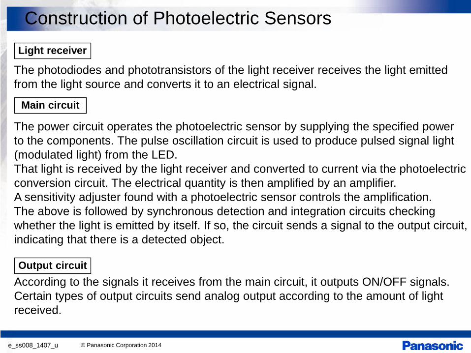
The photodiodes and phototransistors of the light receiver receives the light emitted from the light source and converts it to an electrical signal. The power circuit operates the photoelectric sensor by supplying the specified power to the components. The pulse oscillation circuit is used to produce pulsed signal light (modulated light) from the LED. That light is received by the light receiver and converted to current via the photoelectric conversion circuit. The electrical quantity is then amplified by an amplifier. A sensitivity adjuster found with a photoelectric sensor controls the amplification. The above is followed by synchronous detection and integration circuits checking whether the light is emitted by itself. If so, the circuit sends a signal to the output circuit, indicating that there is a detected object. According to the signals it receives from the main circuit, it outputs ON/OFF signals. Certain types of output circuits send analog output according to the amount of light received.
Light receiver
Main circuit
Output circuit
Construction of Photoelectric Sensors

© Panasonic Corporation 2014 e_ss008_1407_u
ON/OFF signal
Power supply input
Receiving element
Emitting element
LED driver Pulse oscillation circuit
Photoelectric conversion circuit
Amplifier Synchronous detection and
integration circuits
Shaping circuit
Output circuit
Sensitivity control
Operation display
The figure below shows the sensing mechanism of a reflective photoelectric sensor.
Construction of Photoelectric Sensors
© Panasonic Corporation 2014 e_ss008_1407_u
LED driver
Pulse oscillator
Light emitter
Amplifier (VR minimum)
Light receiver
Amplifier (VR maximum)
Detection AND
Synchronization
Integration
Extraneous light, noise
Output
Light emission
Light reception
t ON
OFF OFF
Operating level
Operating level
: response time t
Construction of Photoelectric Sensors
© Panasonic Corporation 2014 e_ss008_1407_u
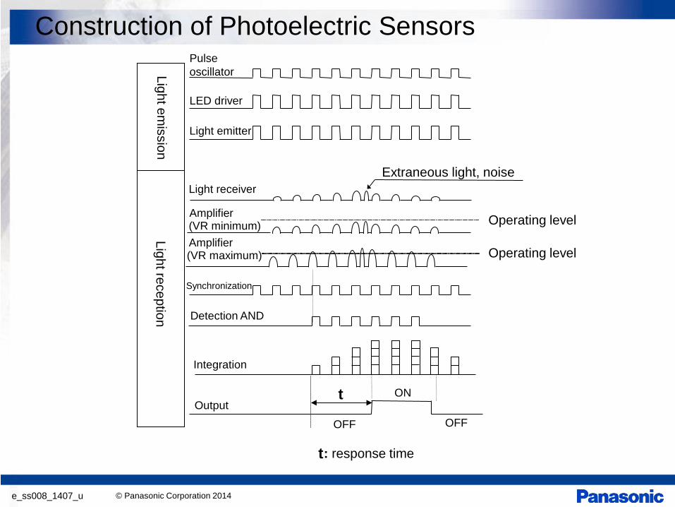
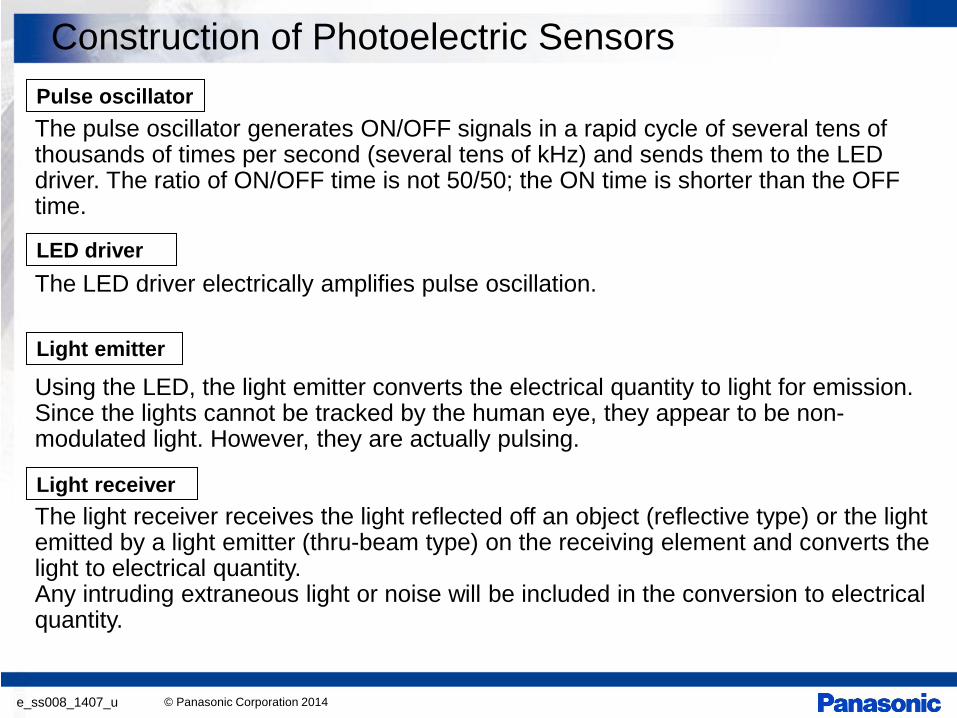
The pulse oscillator generates ON/OFF signals in a rapid cycle of several tens of thousands of times per second (several tens of kHz) and sends them to the LED driver. The ratio of ON/OFF time is not 50/50; the ON time is shorter than the OFF time. The LED driver electrically amplifies pulse oscillation. Using the LED, the light emitter converts the electrical quantity to light for emission. Since the lights cannot be tracked by the human eye, they appear to be non-modulated light. However, they are actually pulsing. The light receiver receives the light reflected off an object (reflective type) or the light emitted by a light emitter (thru-beam type) on the receiving element and converts the light to electrical quantity. Any intruding extraneous light or noise will be included in the conversion to electrical quantity.
Pulse oscillator
LED driver
Light emitter
Light receiver
Construction of Photoelectric Sensors

© Panasonic Corporation 2014 e_ss008_1407_u
As the electrical quantity produced in the conversion by the receiving element is very small, it is amplified by an amplifier. An adjuster is provided to control the level of amplification. This control allows for the determination of the level of light entry needed to validate signals. The pulses generated in the pulse oscillation circuit are sent to the detection circuit as timing signals. Due to the construction, synchronization is not used in thru-beam types except for U-shaped types. However, there are thru-beam type models that use synchronization by connecting the light emitter and light receiver. A logical AND is performed on the amplified signals that are over the operating level and the timing signals from the pulse oscillation circuit. Non-modulated light (sunlight), as well as extraneous light and noise, which entered with a different timing, are eliminated at this point. In order to prevent erroneous operation, output is not produced based on only one signal. It is produced when the specified number of pulses has been reached. The output circuit converts the photoelectric sensor status (detected/not detected) to ON/OFF switch signals for transmission to the connecting device (for example, PLC).
Amplifier
Synchronization
Detection
Integration
Output
Construction of Photoelectric Sensors

© Panasonic Corporation 2014 e_ss008_1407_u
How does a photoelectric sensor detect an object? Here, you will learn about the nature of the working principle. By understanding the nature of the working principle, you can understand how to select the suitable photoelectric sensor type and how to use/adjust the photoelectric sensors. A photoelectric sensor uses light as a medium. It captures the change in light depending on the object of detection. Capturing the object of detection by using a photoelectric sensor is generally called “detection.” In other words: “To detect” is to identify the difference in the quantity of light that enters the sensor when an object is present and when it is absent.
How Does a Photoelectric Sensor Detect Objects?

© Panasonic Corporation 2014 e_ss008_1407_u
For example, if you were to “detect” an object (a bottle is used in this example) using a reflective photoelectric sensor, when a bottle is not there, there is no reflected light and therefore there is a very limited quantity of light received (zero). When a bottle is present, there is significant quantity of reflected light, which means that there is a difference in light quantity between the two states. (Excluding adjustable range reflective type, FZ-10 series, LX-100 series (in color mode)) When the respective quantities of light hitting the sensor when an object is present and when it is not present have the “operating level” somewhere in between, such a condition indicates that a change is identified. This means that the object is detected.
No light has entered Light has entered
Ligh
t qua
ntity
Ligh
t qua
ntity
Significant light quantity No or little light quantity
Operating level
Operating level
No light entry
Light entry
Bot
tle
Reflective photoelectric sensor Reflective photoelectric sensor
Note: There is actually hysteresis aside from the operating level. However, it is omitted from this example for the purpose of explaining the concept.
How Does a Photoelectric Sensor Detect Objects?

© Panasonic Corporation 2014 e_ss008_1407_u
Therefore, selecting a sensing type (thru-beam / retroreflective / reflective) and/or light source color that makes for a greater difference in light quantity and adjusting the sensitivity so that the difference in light quantity can be identified, lead to an appropriate selection of sensing type and a correct use/adjustment of each type.
(Example of selecting the sensing type)
When sensing a transparent plastic bottle, a light attenuation occurs when the light passes through a “wall” of the plastic bottle. With the thru-beam type, the light is transmitted through the wall twice. However, the retroreflective type passes light through the wall 4 times, consequently allowing for greater sensitivity to the change in light (difference of light intensity).
2nd pass 1st pass 2nd pass 1st pass
3rd pass 4th pass <Thru-beam type> <Retroreflective type>
Plastic bottle Plastic bottle
How Does a Photoelectric Sensor Detect Objects?

© Panasonic Corporation 2014 e_ss008_1407_u
Next, let’s look at a specific case about adjusting the sensitivity to identify the difference in light quantity using the thru-beam photoelectric sensor. First, we will think about a case where the sensed object is opaque and can completely interrupt the effective beam. In this case, detection is possible even when the sensitivity adjuster is set to MAX. (In other words, sensing is available even without sensitivity adjustment.)
Ligh
t qua
ntity
Small light quantity (zero)
Light interrupted
Large light quantity
Ligh
t qua
ntity
Operating level
Light entering
Output OFF (Operation setting: Dark-ON) Output ON (Operation setting: Dark-ON)
Operating level
How Does a Photoelectric Sensor Detect Objects?

© Panasonic Corporation 2014 e_ss008_1407_u
Next, we will take a look at a case where the sensed object is a business card. A part of the light emitted from the emitter passes through the object and reaches the receiver. (Part of the light reflects off the object.) Therefore, when a business card is present, while there is some difference in light quantity with when there is no business card, because both have a light quantity above the operating level, the difference is not identified.
Large light quantity
Ligh
t qua
ntity
Operating level
Light entering
Output OFF (Operating setting: Dark-ON) Output OFF (Operating setting: Dark-ON)
No difference identified = No detection
Ligh
t qua
ntity
Large light quantity (smaller than when there is no business card)
Light entering
Operating level
Difference in light quantity between when a business card is present and when it is absent
How Does a Photoelectric Sensor Detect Objects?
(business card)

© Panasonic Corporation 2014 e_ss008_1407_u
Then, what we should do is to adjust the sensitivity (lower the amplification of the light receiver) in order to reduce the light quantity. By doing this, the operating level is between the respective light quantities of when a business card is present and when it is absent, and therefore the difference (detection) can be identified.
In general, sensitivity is adjusted using the sensitivity adjuster in the light receiver. However, some models adjust sensitivity by controlling the light emission or the operating level.
Before sensitivity
adjustment
Ligh
t qua
ntity
Operating level
Light entering
Output OFF (Operating setting: Dark-ON) Output ON (Operating setting: Dark-ON)
Ligh
t qua
ntity
Light interrupted
Operating level
After sensitivity
adjustment
Difference identified = Can be detected
How Does a Photoelectric Sensor Detect Objects?
Before sensitivity
adjustment
After sensitivity
adjustment
(business card)

© Panasonic Corporation 2014 e_ss008_1407_u
Retroreflective type sensor with polarizing filters
Opposite types of polarizing filters are placed in front of the emitting and receiving elements. A horizontal polarizing filter placed in front of the emitting element passes only horizontally polarized light and a vertical polarizing filter placed in front of the receiver ensures that only vertically polarized light is received. Using this configuration, even specular objects can be reliably detected. (1) Normal light emitted from the emitting element oscillates
in a random manner. As it passes through the horizontal polarizing filter, the oscillation is aligned horizontally and the beam is horizontally polarized.
(2) When the polarized beam falls on the reflector, its polarization is destroyed and the reflected beam oscillates in a random manner. So, the reflected beam can pass through the vertical polarizing filter and reach the receiving element.
However, a specular object does not destroy the polarization. The reflected beam oscillates horizontally, as before, and cannot pass through the vertical polarizing filter to reach the receiving element.
Principles of Particular Optical Sensing Systems

© Panasonic Corporation 2014 e_ss008_1407_u
Retroreflective type sensor with polarizing filters
Compact photoelectric sensor CX-491
Principles of Particular Optical Sensing Systems
Detection of white appliances with glossy surface
Passage detection on conveyor

© Panasonic Corporation 2014 e_ss008_1407_u
By applying the principles of the retroreflective type sensors with polarizing filters, mutual interference can be prevented with thru-beam photoelectric sensors.
(1) Beam emitted from Sensor A’s emitting element oscillates in all directions, but the horizontal interference prevention filter PF-CX4-H fitted on the light emitter polarizes the light in the horizontal direction.
(2) The polarized light can enter a light receiver fitted with a horizontal interference prevention filter PF-CX4-H, but cannot enter the light receiver of Sensor B that is fitted with the vertical interference prevention filter PF-CX4-V.
(3) The light emitter and receiver of Sensor B are fitted with vertical interference prevention filter PF-CX4-V, and the same principle applies.
The filters are provided specifically for CX-411 and NX5-M10R□. Interference is prevented by using dual-direction interference prevention filters.
Principles of Particular Optical Sensing Systems
Example: CX-411
Sensor A
Sensor B

© Panasonic Corporation 2014 e_ss008_1407_u
Emitting element
Emitting element
Receiving element
Receiving element
Sensor B
Sensor A Interference prevention filter PF-CX4-H
Interference prevention filter PF-CX4-H
Interference prevention filter PF-CX4-V
Interference prevention filter PF-CX4-V
Note that the figure only shows oscillation in the vertical and horizontal directions, but the beam actually oscillates in all directions.
Principles of Particular Optical Sensing Systems

© Panasonic Corporation 2014 e_ss008_1407_u
Adjustable range reflective type photoelectric sensor
Employing the optical triangulation method, it reliably senses an object at a given distance, irrespective of its reflectivity, by measuring the angle of the received beam.
Principles of Particular Optical Sensing Systems
Compact beam sensor CX-440 series
It contains an emitting lens and a receiving lens. The beam from the emitting lens falls on the sensing object and, after being reflected, is guided by the receiving lens onto a 2-segment diode. Here, the sensing object distance is determined by taking the position at which the upper and lower segments of the 2-segment photodiode generate equal output voltages as the reference. This method, besides being suitable for long distance, is also good for high accuracy position alignment. Further, the equal output voltages are obtained by adjusting the position of the receiving lens.

© Panasonic Corporation 2014 e_ss008_1407_u
When light emitted from the sensor’s emitting element (visible red light) hits the sensing object, the reflected light forms a spot image on the receiving element (2-segment element). Based on the position of the spot (center-of-gravity position), the distance of the sensing object is calculated internally. As shown in the figure to the right, when the center-of-gravity position of the light quantity (spot) is at the [a] side of the 2-segment element, it is determined that there is light. The set distance L is determined by moving the receiving lens up/down so that the spot position comes to the center of the 2-segment element.
a
b
2-segment element
Emitting element
A B C
Sensing plate
Emitting lens
Receiving lens
Spot position
2-segment element
Point A
Point B
Point C
Reflected light (spot beam)
Set distance L
a
b
Principles of Particular Optical Sensing Systems

© Panasonic Corporation 2014 e_ss008_1407_u
Digital mark sensor: LX-100 series The optimal light source is automatically selected from the 3 colors of the R · G · B LEDs so that the contrast between the mark and base becomes the largest. This makes detection more stable. The color mode utilizes all the R · G · B LEDs and detects the reflected light by calculating the R · G · B ratio. Thus, high precision detection is possible by sensing only the mark color that teaching was performed on.
When the mark mode is set
When the color mode is set
Principles of Particular Optical Sensing Systems

© Panasonic Corporation 2014 e_ss008_1407_u
Liquid level detection sensor (pipe-mountable): EX-F1 When the pipe is empty, the beam is reflected from the inner surface of the pipe wall and returns to the beam-receiving part, since the difference in the refractive indexes of the pipe and air is large. When there is liquid in the pipe, the beam enters the liquid through the wall and does not return to the beam-receiving part, since the difference in the refractive indexes of the pipe and the liquid is small.
Principles of Particular Optical Sensing Systems

© Panasonic Corporation 2014 e_ss008_1407_u
Leak detection sensor Leaks in small amounts and viscous liquids can be quickly and accurately detected by taking advantage of the capillary effect. When there is a leak, the beam from the light emitter diffuses in the leaked liquid and creates a non-light entering state.
Beam from the emitter diffuses and does not enter the receiver.
Beam from the emitter reflects on the sensing surface and enters the receiver.
Capillary effect
Sensing principle of the new mode
Principles of Particular Optical Sensing Systems
Capillary effect Sensor body
Leak pan
Liquid
<When there is a leak> <When there is no leak>
Emitter Emitter Receiver Receiver
Leak Sensing surface Sensing surface
Leak pan Leak pan