baumer-gapi 2 sdk installation guide for microsoft...
TRANSCRIPT

Baumer-GAPI 2 SDKInstallation Guide for Microsoft® Windows®
2
1. Introduction 3
2. Technical Background 3
2.1 Interfaces 3
2.2 Baumer-GAPI2 32.2.1 Components of the Baumer-GAPI 2 stack 3
3. General System Requirements 4
4. Installation 4
4.1 Hardware Installation / Configuration 44.1.1 Hardware Driver for Intel® Chipset 54.1.2 Configuration of Link Aggregation (LAG) 64.1.3 Receive Buffer Configuration 7
4.2 Software Installation 84.2.1 Preliminary steps 84.2.2 Installation of Baumer-GAPI2 94.2.3 Installation of Baumer Filter Driver 11
5. Removal 12
5.1 Removal Baumer Filter Driver 12
Table of Contents5.2 Removal of Baumer-GAPI2 13
6. Network Settings 14
6.1 IP Configuration 14
6.2 Configuration of “Jumbo Frames” 156.2.1 Configuration of “Jumbo Frames” - Single-GigE 156.2.2 Configuration of “Jumbo Frames” - Dual-GigE 16
7. Support 17
3
Introduction1. This installation guide addresses both users who wish to change camera settings, make and view camera images as well as program-mers who need to integrate Baumer cameras in their own software.
Technical 2. Background
Interfaces2.1 BGAPI2 supports the following interfaces:
GigE ▪
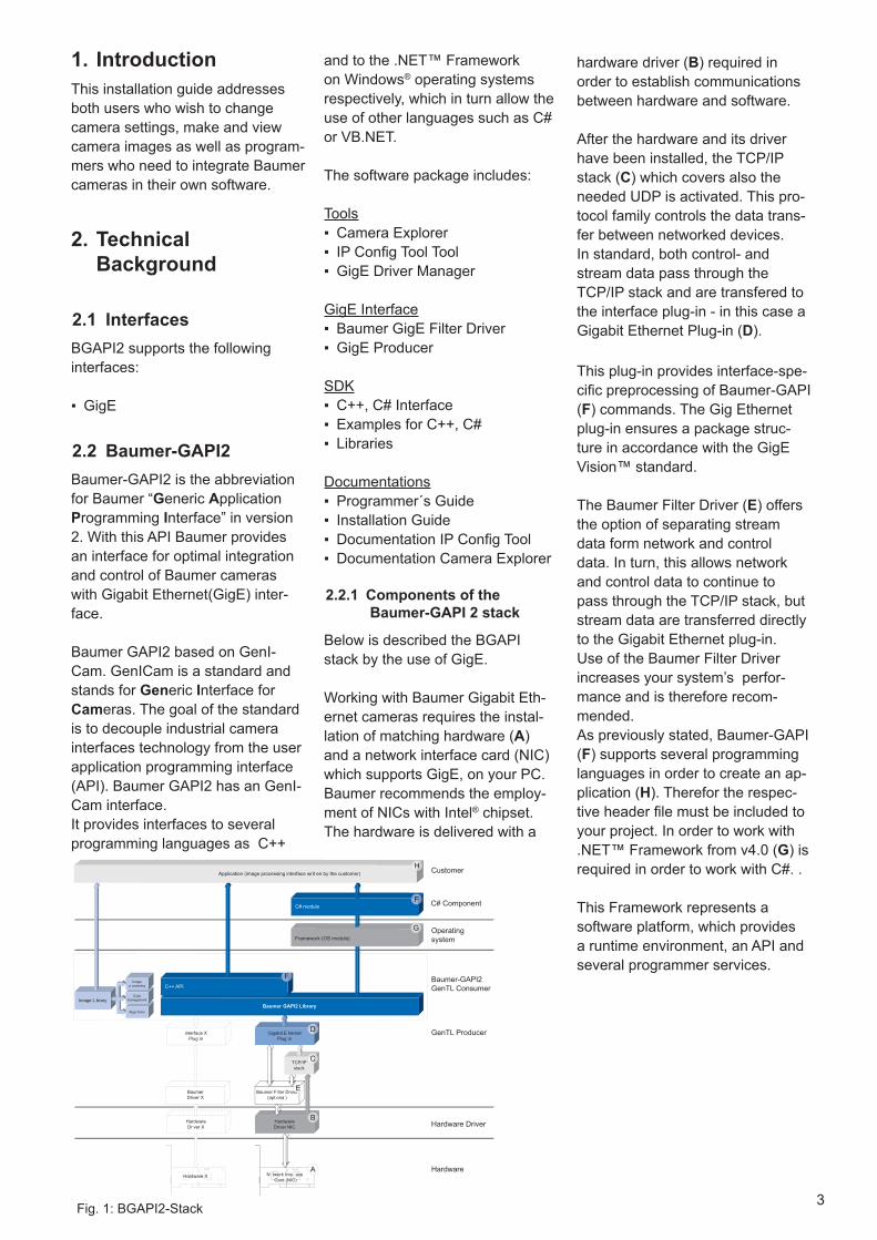
Baumer-GAPI22.2 Baumer-GAPI2 is the abbreviation for Baumer “Generic Application Programming Interface” in version 2. With this API Baumer provides an interface for optimal integration and control of Baumer cameras with Gigabit Ethernet(GigE) inter-face.
Baumer GAPI2 based on GenI-Cam. GenICam is a standard and stands for Generic Interface for Cameras. The goal of the standard is to decouple industrial camera interfaces technology from the user application programming interface (API). Baumer GAPI2 has an GenI-Cam interface.It provides interfaces to several programming languages as C++
hardware driver (B) required in order to establish communications between hardware and software.
After the hardware and its driver have been installed, the TCP/IP stack (C) which covers also the needed UDP is activated. This pro-tocol family controls the data trans-fer between networked devices.In standard, both control- and stream data pass through the TCP/IP stack and are transfered to the interface plug-in - in this case a Gigabit Ethernet Plug-in (D).
This plug-in provides interface-spe-cific preprocessing of Baumer-GAPI (F) commands. The Gig Ethernet plug-in ensures a package struc-ture in accordance with the GigE Vision™ standard.
The Baumer Filter Driver (E) offers the option of separating stream data form network and control data. In turn, this allows network and control data to continue to pass through the TCP/IP stack, but stream data are transferred directly to the Gigabit Ethernet plug-in. Use of the Baumer Filter Driver increases your system’s perfor-mance and is therefore recom-mended.As previously stated, Baumer-GAPI (F) supports several programming languages in order to create an ap-plication (H). Therefor the respec-tive header file must be included to your project. In order to work with .NET™ Framework from v4.0 (G) is required in order to work with C#. .
This Framework represents a software platform, which provides a runtime environment, an API and several programmer services.
and to the .NET™ Framework on Windows® operating systems respectively, which in turn allow the use of other languages such as C# or VB.NET.
The software package includes:
ToolsCamera Explorer ▪IP Config Tool Tool ▪GigE Driver Manager ▪
GigE InterfaceBaumer GigE Filter Driver ▪GigE Producer ▪
SDKC++, C# Interface ▪Examples for C++, C# ▪Libraries ▪
DocumentationsProgrammer´s Guide ▪Installation Guide ▪Documentation IP Config Tool ▪Documentation Camera Explorer ▪
Components of the 2.2.1 Baumer-GAPI 2 stack
Below is described the BGAPI stack by the use of GigE.
Working with Baumer Gigabit Eth-ernet cameras requires the instal-lation of matching hardware (A) and a network interface card (NIC) which supports GigE, on your PC. Baumer recommends the employ-ment of NICs with Intel® chipset. The hardware is delivered with a
HardwareDriver NIC
TCP/IPstack
Gigabit E hernetPlug in
Baumer F lter Driver(opt ona )
N twork Inte ace Card (NIC)
Hardware Driver
Hardware
Customer
C# Component
Operatingsystem
Baumer-GAPI2GenTL Consumer
GenTL Producer
Image L braryColor
management
Imagep ocessing
Algor thms
HardwareDr ver X
BaumerDriver X
interface XPlug in
Hardware X
Baumer GAPI2 Library
C++ API
Framework (OS module)
C# module
Application (image processing interface writ en by the customer)
verver
Fig. 1: BGAPI2-Stack

4
General System Requirements5. Single-camera system
RecommendedMulti-camera system
RecommendedCPU DUAL-Core, Intel® Xeon® W3503 DUAL-Core, Intel® Xeon® W3503Clock 2.4 GHz 2.4 GHzRAM 4 GB 4 GBOperating system (OS)
Microsoft® Windows® 7 32 / 64 bit systems Microsoft® Windows® 8 32 / 64 bit systems
Graphics Recommended resolution: 1280 x 1024; Color depth: at least 16 bitEthernet Gigabit Ethernet compliant NIC (Recommended: Intel® chipset)Frame-work (optional)
Windows® OS: .NET™ Framework 4.0 or higher for C# implementation
Installation6.
Hardware Installation / 6.1 Configuration
CautionObserve precautions for handling electrostatic sensitive devices!
Network Card (see Fig. 1)Switch the PC off (A). ▪Disconnect the power supply (B). ▪Open the PC housing (C). ▪Place the Network Card into an ▪unused PCI port (If nessacary, re-move the interface slot cover) (D).Close the PC housing (E). ▪Connect the power supply of the ▪PC (H).
▪Camera (see Fig. 2)Connect the camera to the GigE ▪board (1) using an appropriate cable (at least Cat-5e).If required, connect a trigger and/ ▪or flash to the Digial-IO supply (3).Connect the camera to power sup- ▪ply (4).
Feedback of the camera (e.g.SXG): Power on: LED green ▪Readout active: LED yellow ▪
NoticeTo use the camera, the approp-riate drivers for the network card must be installed.
powersupplyunit
PCI slots
side plate
Fig. 1: Installation of the GigE board
Fig. 2: Installation example (Dual-GigE; e.g. HXG/SXG)
1 - Network Interface card (NIC); 2 - GigE cable; 3 - Process interface cable; 4 - Power cable
open wire

5
Fig. 3: Setup Options for the GigE hardware driver
Hardware Driver for Intel6.1.1 ® Chipset
Because Windows® does not in-clude drivers for GigE boards with Intel® chipset, they need to down-loaded from Intel® Website.
NoticeDownload the latest driver for your Operating System from:
http://www.intel.com/support/net-work/sb/CS-006120.htm
Start the downloaded file and fol- ▪low the screen instructions.
→The setup program then extracts the required files and opens a welcome screen.
Click “Next ›“ takes you to the li- ▪cense agreement. Read it care-fully and place a checkmark next to the statement, “I accept the terms of the license agreement”, then click on “Next ›“.
In this step (see Fig. 3) activate ▪the checkboxes for:
Intel ▪ ® PROSet for Windows* Device ManagerAdvanced Network Services ▪
The Simple Network Management Protocol (SNMP) is not required.
Click on “Next ›“ opens an infor- ▪mation screen. Here, click on “In-stall” to start the installation pro-cess.
Once the installation has been ▪completed, click on “Finish”.

6
Configuration of Link Aggregation (LAG)6.1.2
Link Aggregation (LAG) allows grouping the two links of a Dual-GigE camera (e.g. HXG/SXG) to form a “virtual” link, enabling the camera to treat the LAG as if it was a single link.
To connect the a Dual-GigE camera to host using LAG will required two host Ethernet adapter ports. Follow the steps below to setup LAG under Windows 7.
1. Press Start, then choose Control Panel.
2. Click on Hardware and Sound.3. Select Device Manager.4. Click on the Network Adapter.5. Make a right click on Adapter device
name.6. Select Properties.7. Choose the Teaming tab.
NoticeThis tab is only available at Intel Driver (e.g. Intel NIC Treiber 16.3 - 16.8 Win7), not in Win7-standard Driver!
8. Select Team the adapter with other adapter.
9. Click on New Team.
The New Team Wizard window will open. Choose a team name. Click Next.
Select the desired adapters corresponding to the ports to be used by the camera and click Next.
Choose the team type: Static Link Aggregation. Click Next.
→ The configurated adapter will now available in the Network Connection window.

7
Receive Buffer Configuration6.1.3
Use this setting to specify the number of Receive Buffers that the network adapter uses when copying data to memory. Increasing this value can enhance receive performance.
We recommend to increase the value. Make the settings for both network adapters!
1. Press Start, then choose Control Panel.2. Click on Hardware and Sound.3. Select Device Manager.4. Click on the Network Adapter.5. Make a right click on Adapter device
name1.6. Select Properties.7. Choose the tab Advanced.8. Select Performance Options → Properties9. Choose Receive Buffers and set the Value
to 2048. Click OK.
10. Repeat the process for Adapter device name2.

8
Fig. 4: Add or Remove Program screen
Software Installation6.2
Preliminary steps6.2.1
In preparation for the installation of actual Baumer software package, examine the following items:
Has any other version of the BGAPI ▫ 2 software already been installed on your system, we recommend to remove it.
Notice
Coexisting versions of BGAPI 1 and BGAPI 2 on the system represent no problem.
Checking the version of the Microsoft® .NET™ Framework
Which version of Microsoft® .NET™ Framework is installed on your system? Version 4.0 is required for the C# examples.
To check this, open “Start“ → “Control Panel” → “Add or Remove Programs”.
If one or more entries are labeled “Microsoft .NET™ Framework 4”, the correct version has been installed.
NoticeYou can download the version 4 of Microsoft® .NET™ Framework from:
http://www.microsoft.com/down-load/en/details.aspx?id=17718

9
Fig. 5: Start
Installation of Baumer-6.2.2 GAPI2
Insert the BGAPI2-CD into the CD ▪drive.
If autorun not enabled, start the ▪BaumerGAPISDKInstaller_v2.xx.exe from the CD.
→ BGAPI2 Start Screen appears.
Click on the Button ▪ Next>.
Accept the Licence Agreement ▪and click on the button Next>.
Choose a Setup Type. ▪
NoticeThe filter driver need to be installed with the Baumer Driver Manager (see chapter 6.2.3, page 11).
Fig. 6: Licence
Fig. 7: Setup Type

10
Fig. 8: Installation
Choose whether a Desktop Icon ▪and an entry in the Start menu will be created.
Click on the Button ▪ Install.
The installation progress is dis- ▪played with a progress bar.
Click on the Button ▪ Finish> to complete the installation.
Fig. 9: Progress bar
Fig. 10: Installation Finish

11
(and deselect all others).
Click “Apply” to adopt your selec- ▪tion. After that click “OK” to run the installation process.
Installation of Baumer 6.2.3 Filter Driver
NoticeWith Baumer Filter Driver the op-tion of separating of stream data from network and control data is available.
In turn, this allows network and control data to continue to pass through the TCP/IP stack, but stream data are transferred directly to the GigE Vision™ plug-in.
This increase the performance.
In order to install the Baumer ▪Filter Driver you must start the “Baumer Driver Manager”
Start → All Programs → Baumer → Baumer GAPI SDK → GigE Driver Manager (e.g. Win 32)
In order to properly configure the ▪correct driver for your equipment, the installation tool needs to know which network adapters have been installed on your PC. There-fore, click on “Install” to call up a list of all available network adapt-ers.
This may take a few moments dur- ▪ing which “Please wait” is dis-played.
Meanwhile the following message ›can be displayed repeatedly:
In this case, simply click on “In- ›stall”
NoticeThe number of repetitions de-pends on the number of network adapters on your PC.
Once the network adapters have ▪been detected, simply select the Gigabit Ethernet adapter to which the camera has been connected
Fig. 12: Driver selection
Fig. 11: Filter Driver Manager

12
Finally, the application may ask ▪you to restart your PC. Click “OK” to initiate a restart.
Removal7.
Removal Baumer Filter 7.1 Driver
In order to remove the Baumer ▪Filter Driver you must start the “Baumer Driver Manager”
Start → All Programs → Baumer → Baumer GAPI SDK → GigE Driver Manager (e.g. Win 32)
Select the Gigabit Ethernet adapt- ▪er to which the camera has been connected (and deselect all oth-ers).
Finally click the “Uninstall” button ▪and the uninstalling process be-gins.
Fig. 13: Filter Driver Uninstall

13
Fig. 14: Start
Removal of Baumer-7.2 GAPI2
Start → All Programs → Baumer → Baumer GAPI SDK → Modify, Repair or Remove Program
Click on the Button ▪ Remove.
The Removal progress is dis- ▪played with a progress bar.
Click on the Button ▪ Finish to finish the Removal Process.
Fig. 15: Progress bar
Fig. 16: Removal Finish

14
Network Settings8.
IP Configuration8.1 In order to configure the network settings for the transfer of data be-tween the camera and your PC, fol-low the steps listed below:Select “Start” → “Control Panel” ▪→ “Network Connections” to open the “Local Area Connection Prop-erties” window.Double click on the camera’s net- ▪work connection
NoticeLook for the “Device Name” of the network adapter to which the camera is connected.
Next, scroll to the bottom of the ▪“This connection uses the follow-ing items:” field in the “General” register and mark the “Internet Protocol (TCP/IP)” entry before clicking the “Properties” button.This calls up the “Internet Protocol ▪(TCP/IP) Properties” window.
Here, select the “Obtain an IP ad- ▪dress automatically” and “Obtain DNS server address automatical-ly” items.Confirm your selection by clicking ▪“OK”.
NoticeThe camera uses the following methods to request an IP adress:1st Persistent IP2nd DHCP (Dynamic Host Configuration Protocol)3rd LLA (Link-Local Address)
Depending on which method is used, the allocation of the IP ad-ress may take up to 2-3 minutes.The assignment of a persistent IP adress is facilitated by several tools such as the „Baumer-GAPI Viewer“
Connect the camera to the PC and ▪wait until the IP adress has been allocated (max. 2-3 minutes).
Fig. 17: Local Area Connection Properties
Fig. 18: Internet Protocol (TCP/IP) Properties

15
Configuration of 8.2 “Jumbo Frames”
In order to increase camera system efficiency and performance, so-called “Jumbo Frames” need to be configured.
NoticeJumbo Frames are Ethernet frames, which exceed the stan-dard frame size of 1518 bytes. Typical sizes include for example 4, 9, 12 or 16 KB.
However, there is no standard for Jumbo Frames, their size de-pends on the manufacturer.
They are used to decrease the interrupt load of all involved net-work devices.
In order to use Jumbo Frames all network components must sup-port this feature.
The Figure schematically shows “Jumbo Frames” in comparison with standard Ethernet frames concerning throughput and CPU load.
Standard Eth
ernet F
rames
Troughput
CPU
load
Jumbo Frames
Fig. 19 : Advantages of Jumbo Frames
Configuration of “Jumbo Frames” - Single-GigE8.2.1
1. Press Start, then choose Control Panel.2. Click on View network status and tasks.3. Click Local Area Connection.4. Click on Button Properties.5. Click on Configure....6. Choose the tab Settings.7. Click on the tab Advanced.8. Choose Jumbo Packet and set the Value
to highest possible value9. Confirm this setting with OK.
You have set now the Jumbo Frames for the Single-GigE adapter.
16
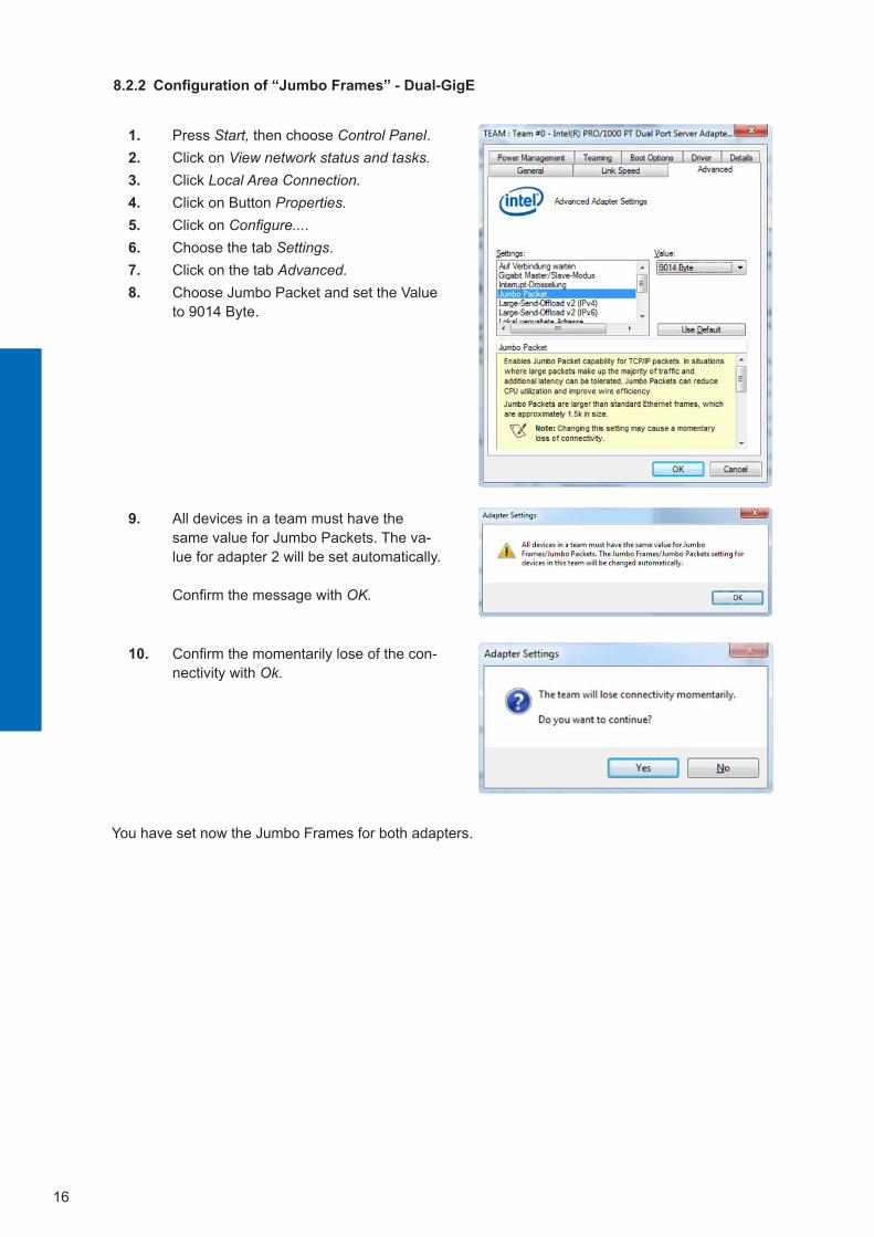
Configuration of “Jumbo Frames” - Dual-GigE8.2.2
1. Press Start, then choose Control Panel.2. Click on View network status and tasks.3. Click Local Area Connection.4. Click on Button Properties.5. Click on Configure....6. Choose the tab Settings.7. Click on the tab Advanced.8. Choose Jumbo Packet and set the Value
to 9014 Byte.
9. All devices in a team must have the same value for Jumbo Packets. The va-lue for adapter 2 will be set automatically.
Confirm the message with OK.
10. Confirm the momentarily lose of the con-nectivity with Ok.
You have set now the Jumbo Frames for both adapters.

17
Support9. If you have any problems with the installation, then feel free to contact our support.
Worldwide
Baumer Optronic GmbHBadstrasse 30DE-01454 Radeberg, Germany
Tel: +49 (0)3528 4386 845
Mail: [email protected]: www.baumer.com

Baumer Optronic GmbHBadstrasse 30DE-01454 Radeberg, GermanyPhone +49 (0)3528 4386 0 · Fax +49 (0)3528 4386 [email protected] · www.baumer.com
Technical data has been fully checked, but accuracy of printed matter not guaranteed.
Subject to change without notice. Printed in Germany 02/13. v1.1 11101903