beam delivery systems: scattering, scanning, w/wo - erice 2009
TRANSCRIPT
Beam Delivery Systems:
Scattering, Scanning, w/wo Gantries
or
Cost Effective Particle Therapy?
Ion Beam Therapy Workshop; Erice,
2009
Jay FlanzMGH/FBTC
Harvard Medical SchoolFlanz 2009 - Erice
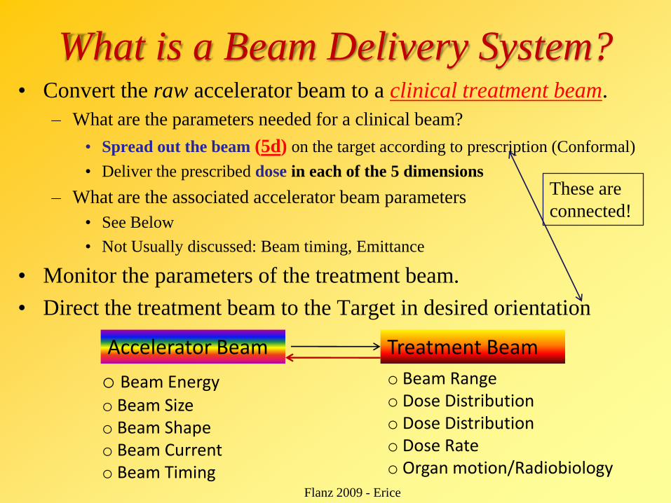
What is a Beam Delivery System?• Convert the raw accelerator beam to a clinical treatment beam.
– What are the parameters needed for a clinical beam?
• Spread out the beam (5d) on the target according to prescription (Conformal)
• Deliver the prescribed dose in each of the 5 dimensions
– What are the associated accelerator beam parameters
• See Below
• Not Usually discussed: Beam timing, Emittance
• Monitor the parameters of the treatment beam.
• Direct the treatment beam to the Target in desired orientation
Accelerator Beam Treatment Beam
o Beam Energyo Beam Sizeo Beam Shapeo Beam Currento Beam Timing
o Beam Rangeo Dose Distributiono Dose Distributiono Dose Rateo Organ motion/Radiobiology
These are
connected!
Flanz 2009 - Erice
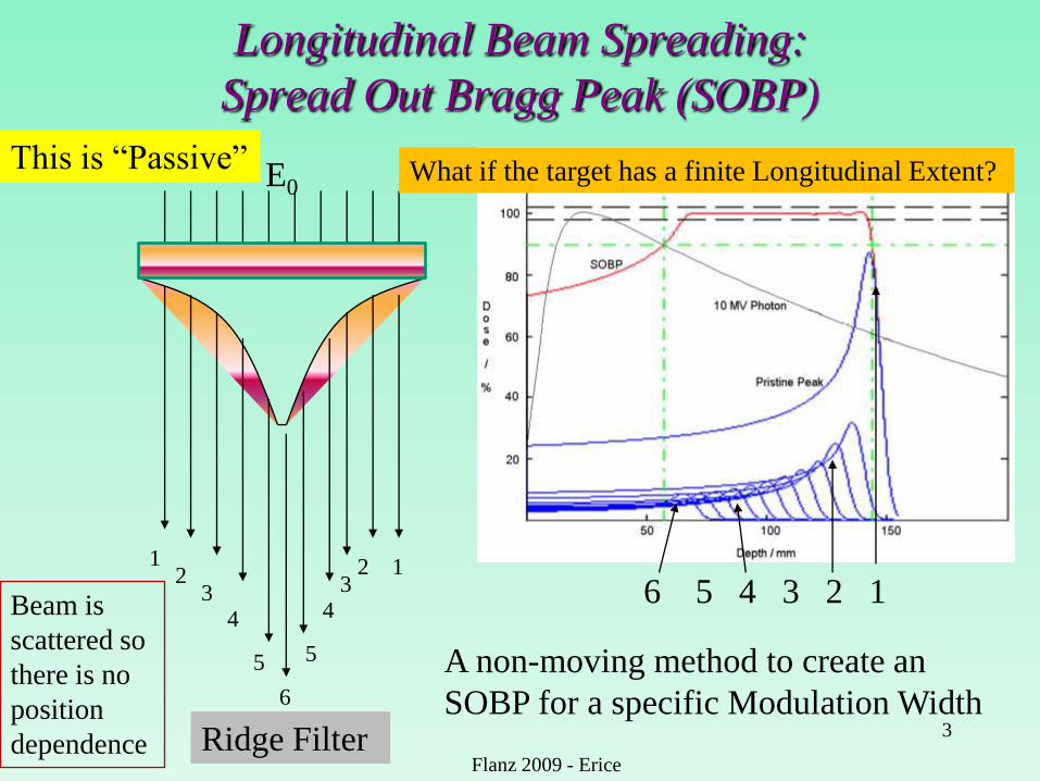
Longitudinal Beam Spreading:
Spread Out Bragg Peak (SOBP)
3
12
34
5
6
5
43
2 1
E0
6 5 4 3 2 1
A non-moving method to create an
SOBP for a specific Modulation Width
This is “Passive”
Ridge Filter
What if the target has a finite Longitudinal Extent?
Flanz 2009 - Erice
Beam is
scattered so
there is no
position
dependence
4
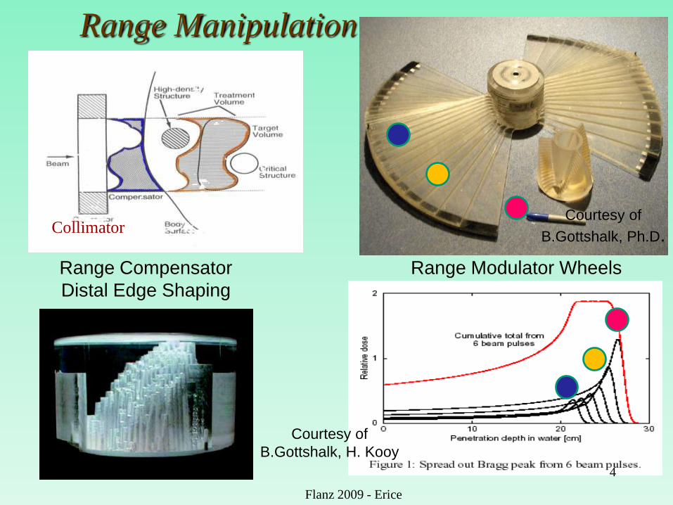
Range Modulator Wheels
Courtesy of
B.Gottshalk, Ph.D.
Range Manipulation
Range Compensator
Distal Edge Shaping
Courtesy of
B.Gottshalk, H. Kooy
Collimator
Flanz 2009 - Erice
Flanz 2009; Riyadh 5
Depth [mm]
0 20 40 60 80 100 120 140
Do
se
[%
]
0
20
40
60
80
100
120
Depth [mm]
0 50 100 150 200
Do
se
[%
]
0
20
40
60
80
100
120
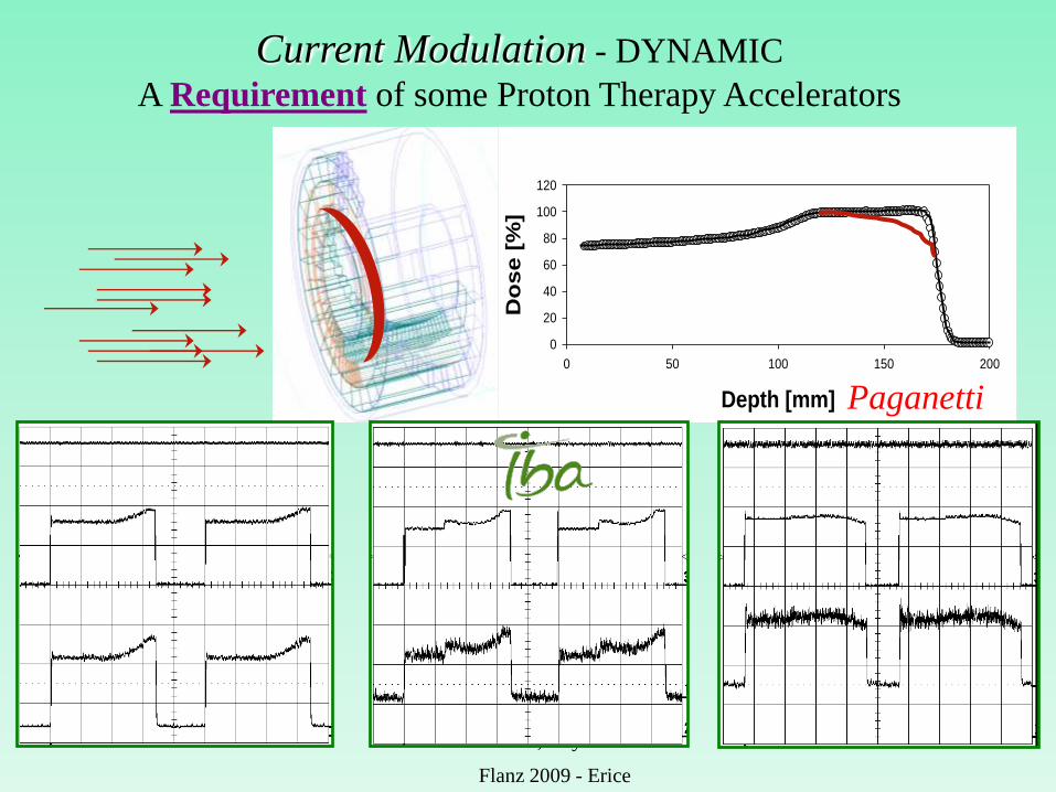
Beam range: 17.19 cmModulation: 6.78 cm
0 20 40 60 80 100 120 140 160
Do
se
[%
]
0
20
40
60
80
100
120
Beam range: 13.47 cmModulation: 8.65 cm
Beam range: 12.0 cmModulation: 4.0 cm
Depth [mm]
Current Modulation - DYNAMIC
A Requirement of some Proton Therapy Accelerators
Paganetti
Flanz 2009 - Erice
Transverse Spreading Options
• Passive Scattering
– Single Scattering
– Double Scattering
• Wobbling (Beam Scanning with Scattered beam)
• Pure Magnetic Scanning
• Combined Magnetic and Mechanical Scanning
– Moving Magnet
– Moving Patient
• Etc.
6
Flanz 2009 - Erice
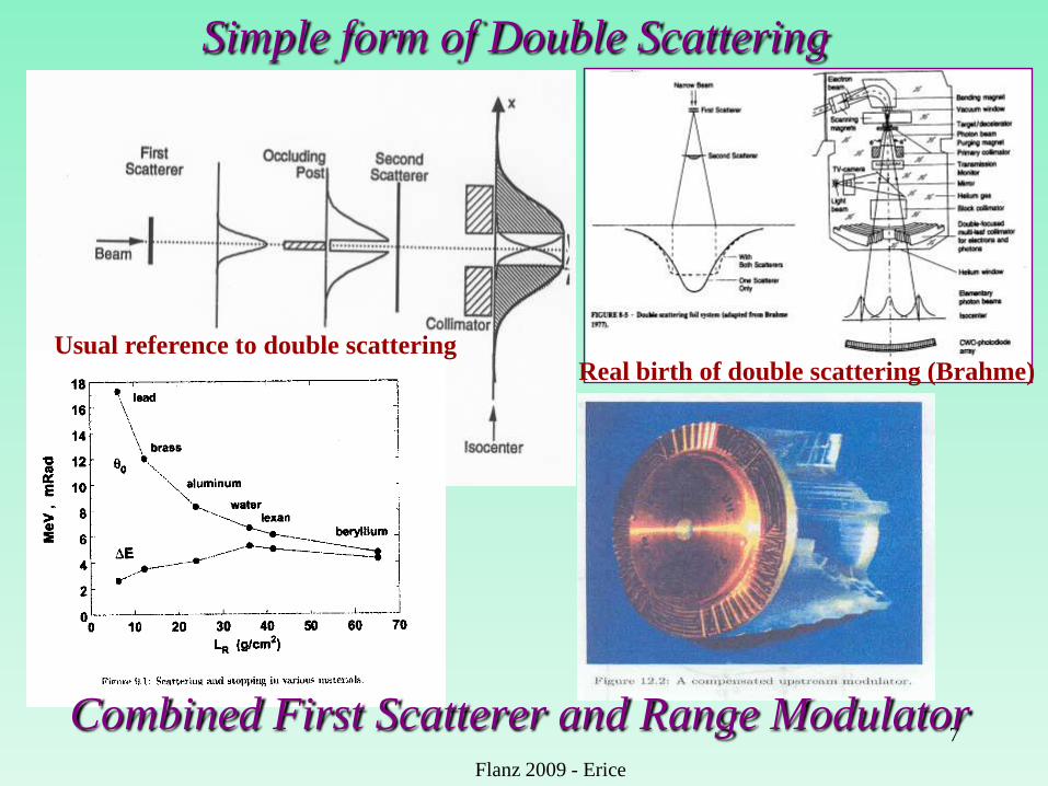
Simple form of Double Scattering
7
Flanz 2009 - Erice
Combined First Scatterer and Range Modulator
Usual reference to double scatteringReal birth of double scattering (Brahme)
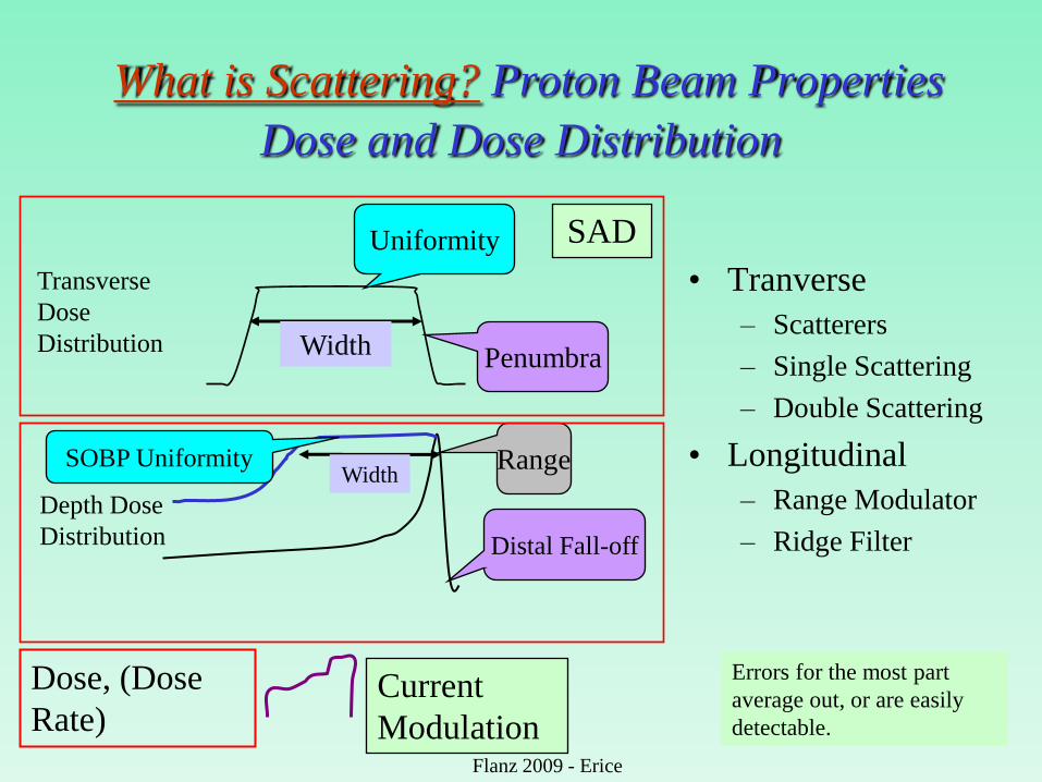
What is Scattering? Proton Beam Properties
Dose and Dose Distribution
Transverse
Dose
Distribution
Depth Dose
Distribution
Uniformity
Penumbra
Distal Fall-off
Range
Dose, (Dose
Rate)
Width
Width
SAD
Current
Modulation
Errors for the most part
average out, or are easily
detectable.
SOBP Uniformity
• Tranverse
– Scatterers
– Single Scattering
– Double Scattering
• Longitudinal
– Range Modulator
– Ridge Filter
Flanz 2009 - Erice
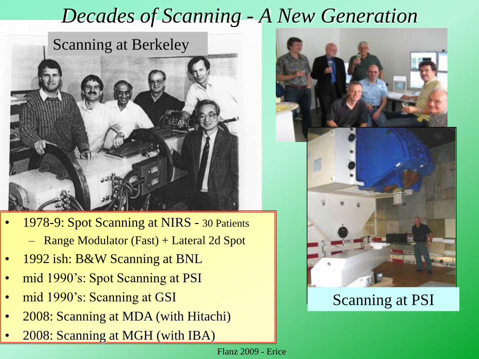
Decades of Scanning - A New Generation
Scanning at Berkeley
Scanning at PSI
• 1978-9: Spot Scanning at NIRS - 30 Patients
– Range Modulator (Fast) + Lateral 2d Spot
• 1992 ish: B&W Scanning at BNL
• mid 1990‟s: Spot Scanning at PSI
• mid 1990‟s: Scanning at GSI
• 2008: Scanning at MDA (with Hitachi)
• 2008: Scanning at MGH (with IBA)Flanz 2009 - Erice
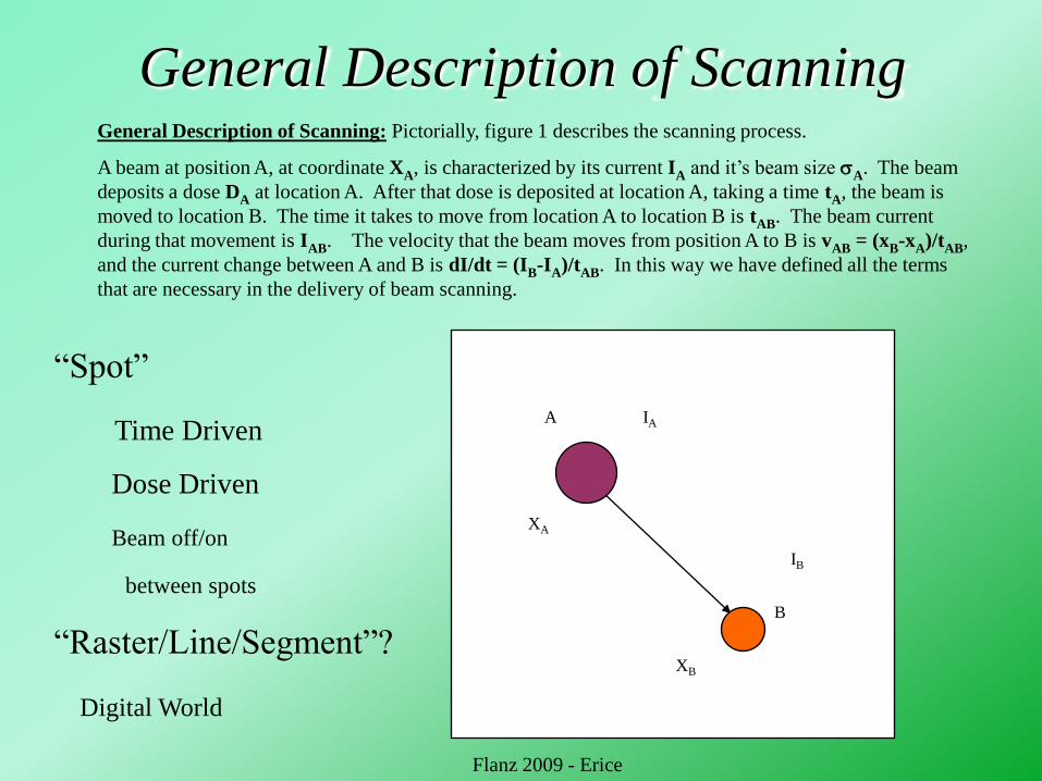
General Description of ScanningGeneral Description of Scanning: Pictorially, figure 1 describes the scanning process.
A beam at position A, at coordinate XA, is characterized by its current IA and it‟s beam size A. The beam
deposits a dose DA at location A. After that dose is deposited at location A, taking a time tA, the beam is
moved to location B. The time it takes to move from location A to location B is tAB. The beam current
during that movement is IAB. The velocity that the beam moves from position A to B is vAB = (xB-xA)/tAB,
and the current change between A and B is dI/dt = (IB-IA)/tAB. In this way we have defined all the terms
that are necessary in the delivery of beam scanning.
A
B
IA
IB
XB
XA
“Spot”
Time Driven
Dose Driven
Beam off/on
between spots
“Raster/Line/Segment”?
Digital World
Flanz 2009 - Erice
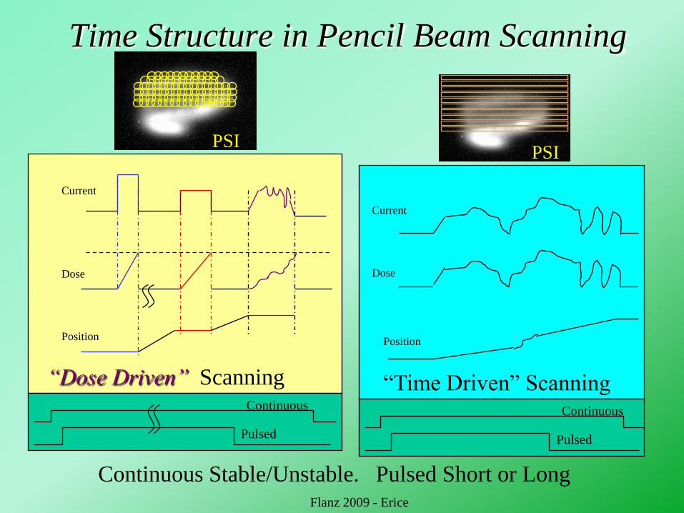
Time Structure in Pencil Beam Scanning
“Dose Driven” Scanning
Current
Dose
Position
Current
Dose
Position
Continuous
Pulsed
Continuous
Pulsed
Continuous Stable/Unstable. Pulsed Short or Long
“Time Driven” Scanning
PSIPSI
Flanz 2009 - Erice
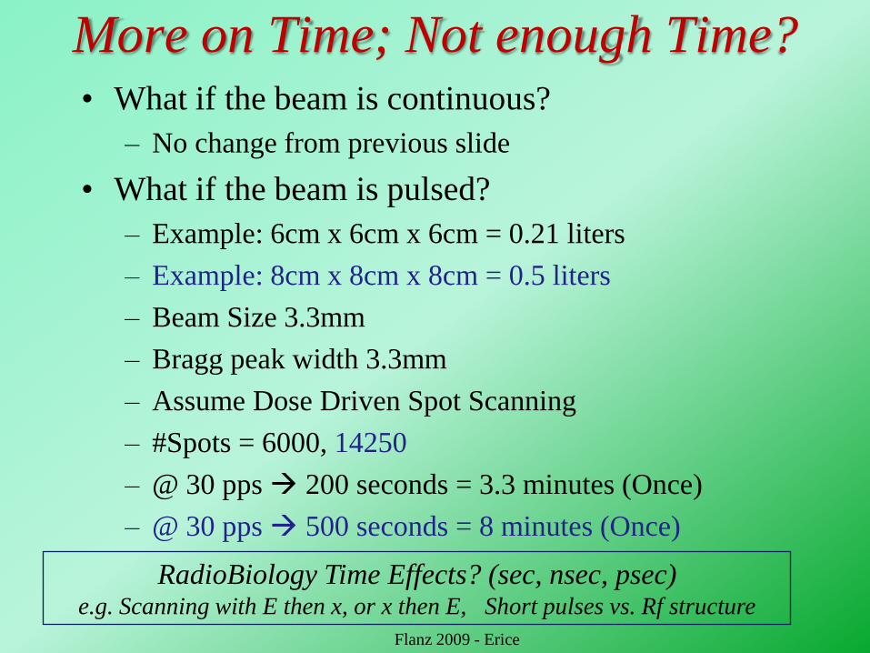
More on Time; Not enough Time?• What if the beam is continuous?
– No change from previous slide
• What if the beam is pulsed?
– Example: 6cm x 6cm x 6cm = 0.21 liters
– Example: 8cm x 8cm x 8cm = 0.5 liters
– Beam Size 3.3mm
– Bragg peak width 3.3mm
– Assume Dose Driven Spot Scanning
– #Spots = 6000, 14250
– @ 30 pps 200 seconds = 3.3 minutes (Once)
– @ 30 pps 500 seconds = 8 minutes (Once)
Flanz 2009 - Erice
RadioBiology Time Effects? (sec, nsec, psec)e.g. Scanning with E then x, or x then E, Short pulses vs. Rf structure

Methods of Dose Driven Scanning: DSS and DET
Not for Distribution Flanz 2009
DET Spot Locations (~20)
- For DET multiple
directions or arc
therapy and
intensity
modulation
required to obtain
uniform dose
distributions.
Distal Edge of Target
Mackey
SS Spot Locations (~300)
Flanz 2009 - Erice

Scanning Proton Beam Properties
Dose and Dose Distribution
Transverse
Dose
Distribution
Depth Dose
Distribution
Penumbra
Distal Fall-off
Range
Dose, (Dose Rate),
Weight, Gradient
Size
Shape
Conformity/
Gradient
SAD• Generalized Scanning
• Uniform Scanning
• Wobbling
Errors are less „intuitive‟ and
may not average out. (Harder
to measure?) Need a basis for
estimating the effects of
errors and tolerances !Flanz 2009 - Erice
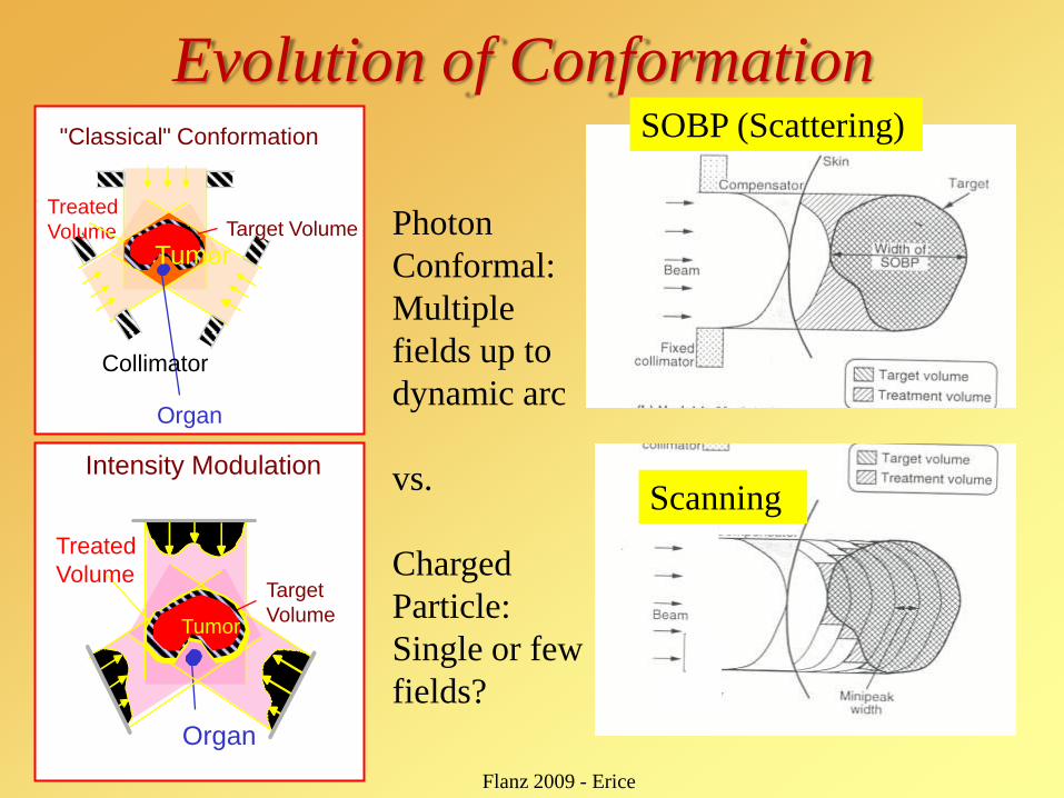
Evolution of Conformation
Tumor
Treated
Volume
Organ
Target Volume
Collimator
"Classical" Conformation
Treated
Volume
Tumor
Organ
Target
Volume
Intensity Modulation
Photon
Conformal:
Multiple
fields up to
dynamic arc
vs.
Charged
Particle:
Single or few
fields?
Scanning
SOBP (Scattering)
Flanz 2009 - Erice
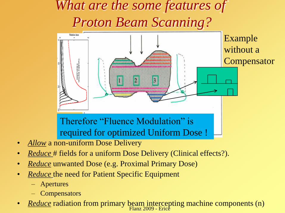
What are the some features of
Proton Beam Scanning?
• Allow a non-uniform Dose Delivery
• Reduce # fields for a uniform Dose Delivery (Clinical effects?).
• Reduce unwanted Dose (e.g. Proximal Primary Dose)
• Reduce the need for Patient Specific Equipment
– Apertures
– Compensators
• Reduce radiation from primary beam intercepting machine components (n)
Therefore “Fluence Modulation” is
required for optimized Uniform Dose !
Flanz 2009 - Erice
Example
without a
Compensator
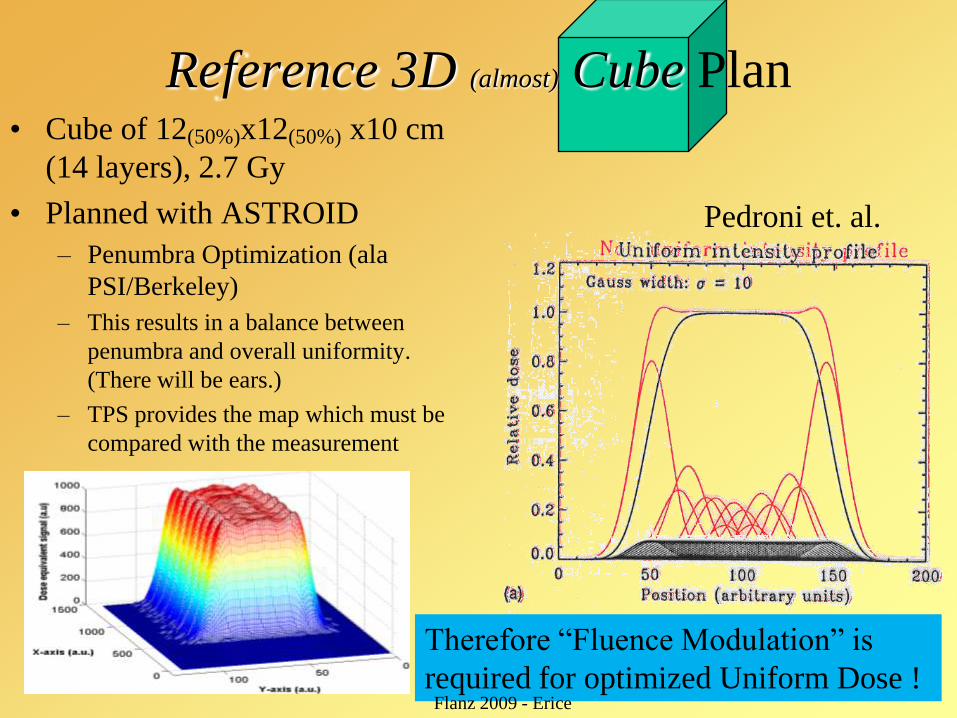
Reference 3D (almost) Cube Plan• Cube of 12(50%)x12(50%) x10 cm
(14 layers), 2.7 Gy
• Planned with ASTROID
– Penumbra Optimization (ala
PSI/Berkeley)
– This results in a balance between
penumbra and overall uniformity.
(There will be ears.)
– TPS provides the map which must be
compared with the measurement
Therefore “Fluence Modulation” is
required for optimized Uniform Dose !Flanz 2009 - Erice
Pedroni et. al.
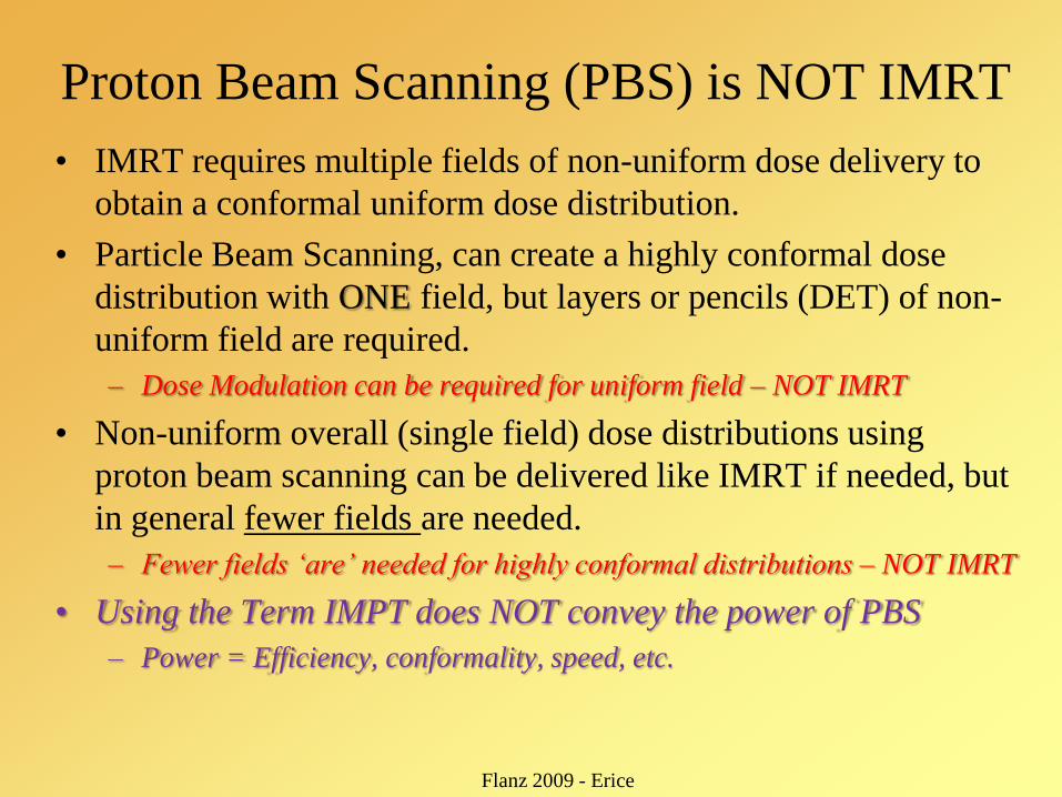
Proton Beam Scanning (PBS) is NOT IMRT
• IMRT requires multiple fields of non-uniform dose delivery to
obtain a conformal uniform dose distribution.
• Particle Beam Scanning, can create a highly conformal dose
distribution with ONE field, but layers or pencils (DET) of non-
uniform field are required.
– Dose Modulation can be required for uniform field – NOT IMRT
• Non-uniform overall (single field) dose distributions using
proton beam scanning can be delivered like IMRT if needed, but
in general fewer fields are needed.
– Fewer fields „are‟ needed for highly conformal distributions – NOT IMRT
• Using the Term IMPT does NOT convey the power of PBS
– Power = Efficiency, conformality, speed, etc.
Flanz 2009 - Erice
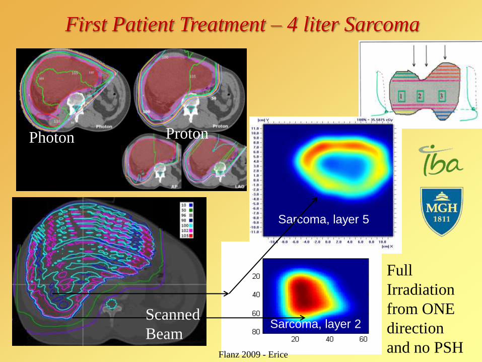
First Patient Treatment – 4 liter Sarcoma
Sarcoma, layer 5
Sarcoma, layer 2
Photon Proton
Scanned
Beam
Flanz 2009 - Erice
Full
Irradiation
from ONE
direction
and no PSH
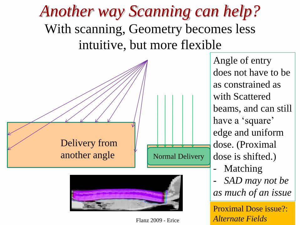
Another way Scanning can help?With scanning, Geometry becomes less
intuitive, but more flexibleAngle of entry
does not have to be
as constrained as
with Scattered
beams, and can still
have a „square‟
edge and uniform
dose. (Proximal
dose is shifted.)
- Matching
- SAD may not be
as much of an issue
Flanz 2009 - Erice
Normal Delivery
Delivery from
another angle
Proximal Dose issue?:
Alternate Fields

Do we need a Gantry?
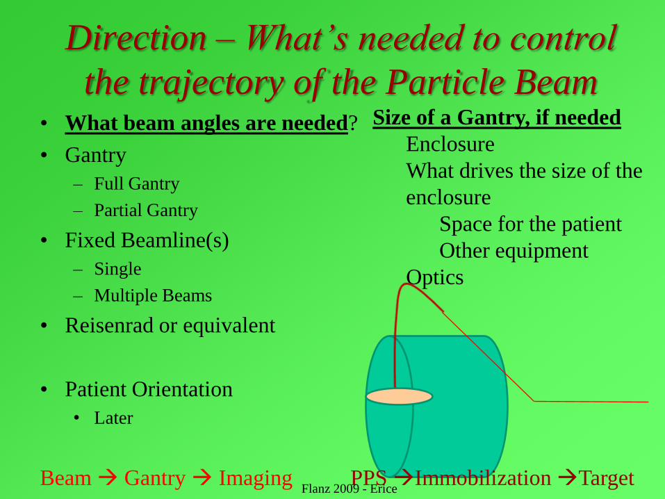
Direction – What‟s needed to control
the trajectory of the Particle Beam• What beam angles are needed?
• Gantry
– Full Gantry
– Partial Gantry
• Fixed Beamline(s)
– Single
– Multiple Beams
• Reisenrad or equivalent
• Patient Orientation
• Later
Size of a Gantry, if needed
Enclosure
What drives the size of the
enclosure
Space for the patient
Other equipment
Optics
Beam Gantry Imaging PPS Immobilization TargetFlanz 2009 - Erice
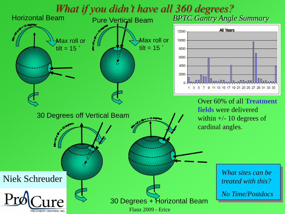
Max roll or
tilt = 15 ˚
Horizontal Beam
Max roll or
tilt = 15 ˚
Pure Vertical Beam
30 Degrees off Vertical Beam
30 Degrees + Horizontal Beam
Niek Schreuder
ProCure
BPTC Gantry Angle Summary
Over 60% of all Treatment
fields were delivered
within +/- 10 degrees of
cardinal angles.
What sites can be
treated with this?
No Time/Postdocs
Flanz 2009 - Erice
What if you didn‟t have all 360 degrees?
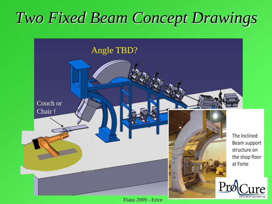
Two Fixed Beam Concept Drawings
Couch or
Chair !
Angle TBD?
Flanz 2009 - Erice
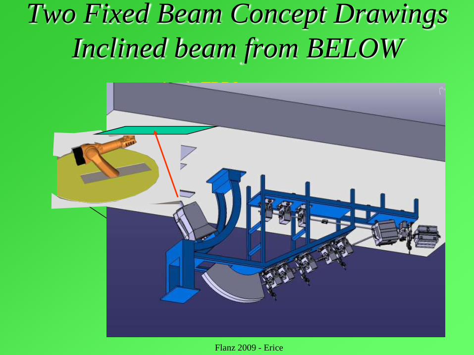
Two Fixed Beam Concept Drawings
Inclined beam from BELOW
Couch or
Chair !
Angle TBD?
Flanz 2009 - Erice
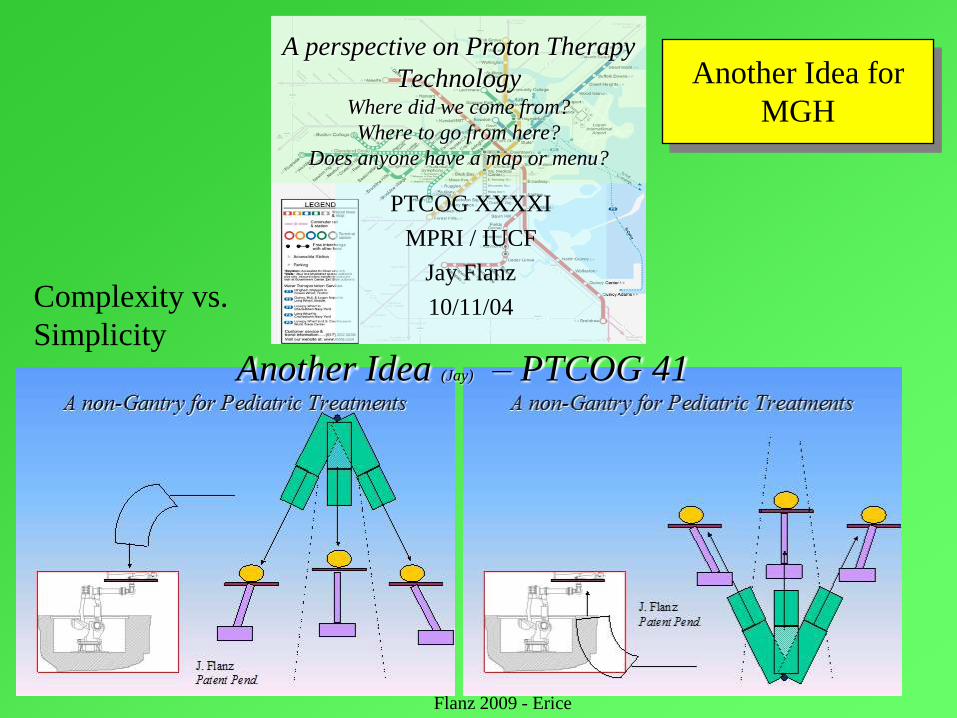
A perspective on Proton Therapy
TechnologyWhere did we come from?
Where to go from here?
Does anyone have a map or menu?
PTCOG XXXXI
MPRI / IUCF
Jay Flanz
10/11/04
Another Idea (Jay) – PTCOG 41
Complexity vs.
Simplicity
Another Idea for
MGH
Flanz 2009 - Erice

Beam angles DEPEND on patient orientation
• Lying, Sitting, Standing
• Reproducibility (Day to Day?)
• How long can position be
maintained (sec, min??)
• Knowledge of existing
anatomy/tumor location and
shape and required treatment
plan du jour
• Imaging, True adaptive planning
Flanz 2009 - Erice
Siemens ProCureIBA, Hitachi
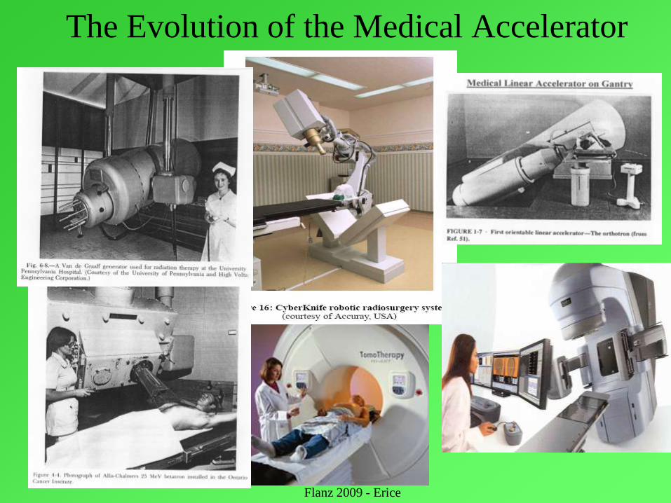
The Evolution of the Medical Accelerator
Flanz 2009 - Erice
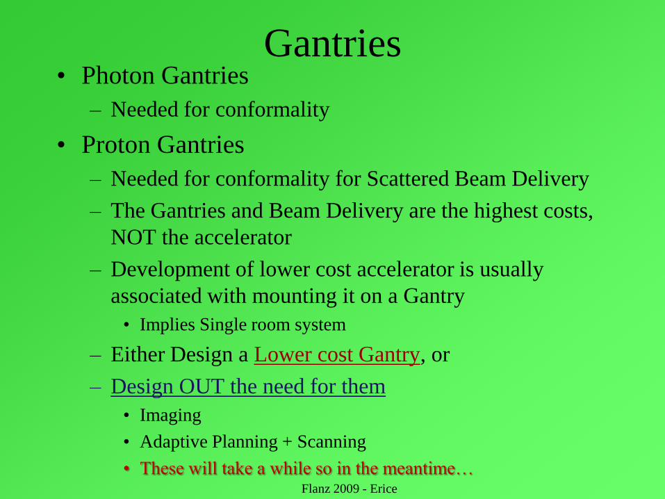
Gantries• Photon Gantries
– Needed for conformality
• Proton Gantries
– Needed for conformality for Scattered Beam Delivery
– The Gantries and Beam Delivery are the highest costs,
NOT the accelerator
– Development of lower cost accelerator is usually
associated with mounting it on a Gantry
• Implies Single room system
– Either Design a Lower cost Gantry, or
– Design OUT the need for them
• Imaging
• Adaptive Planning + Scanning
• These will take a while so in the meantime… Flanz 2009 - Erice
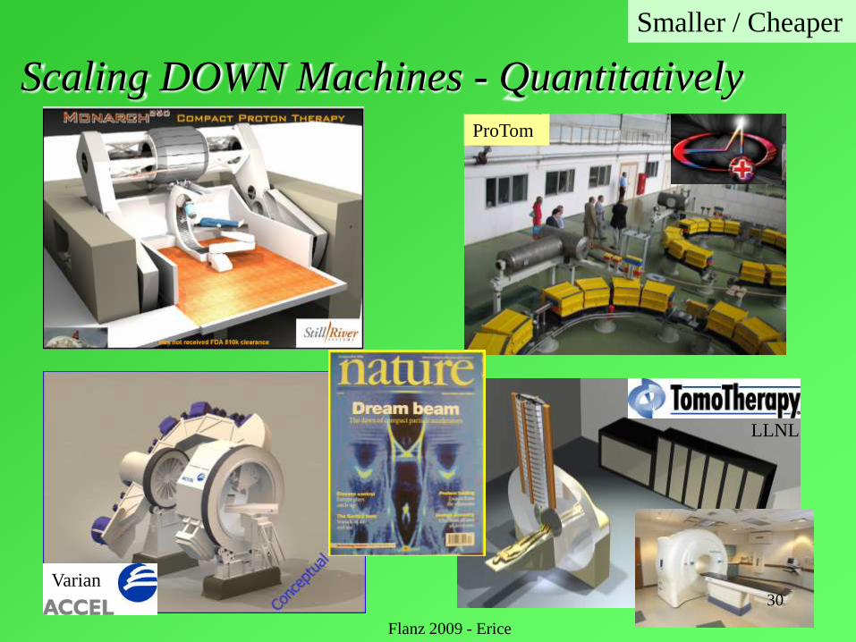
Scaling DOWN Machines - Quantitatively
Smaller / Cheaper
LLNL
ProTom
30
Varian
Flanz 2009 - Erice

If we need a Gantry, what are
some of the considerations?
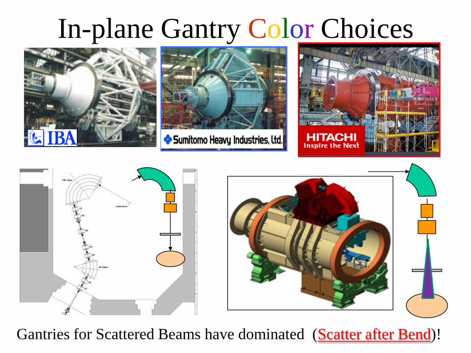
In-plane Gantry Color Choices
Gantries for Scattered Beams have dominated (Scatter after Bend)!
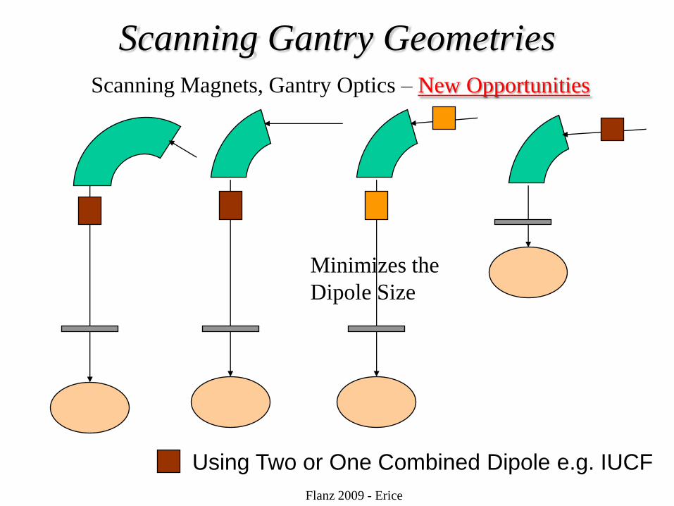
Scanning Gantry Geometries
Using Two or One Combined Dipole e.g. IUCF
Flanz 2009 - Erice
Scanning Magnets, Gantry Optics – New Opportunities
Minimizes the
Dipole Size
Innovative Gantry DesignSee Dejan‟s talk
Some Gantry Design Considerations (If you really need/want one)
Flanz 2009 - Erice
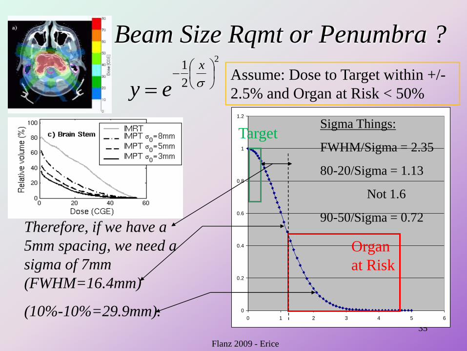
Beam Size Rqmt or Penumbra ?
35
0
0.2
0.4
0.6
0.8
1
1.2
0 1 2 3 4 5 6
Sigma Things:
FWHM/Sigma = 2.35
80-20/Sigma = 1.13
Not 1.6
90-50/Sigma = 0.72Therefore, if we have a
5mm spacing, we need a
sigma of 7mm
(FWHM=16.4mm)
(10%-10%=29.9mm).
2
2
1
x
ey
Flanz 2009 - Erice
Organ
at Risk
Target
Assume: Dose to Target within +/-
2.5% and Organ at Risk < 50%
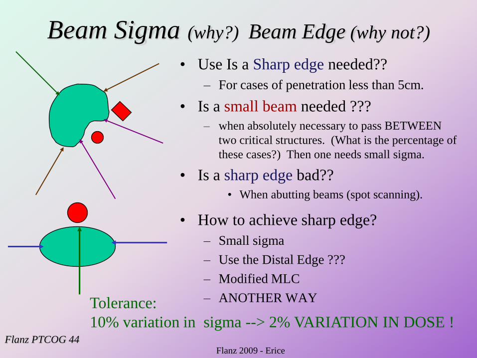
Beam Sigma (why?) Beam Edge (why not?)
• Use Is a Sharp edge needed??
– For cases of penetration less than 5cm.
• Is a small beam needed ???
– when absolutely necessary to pass BETWEEN
two critical structures. (What is the percentage of
these cases?) Then one needs small sigma.
• Is a sharp edge bad??
• When abutting beams (spot scanning).
• How to achieve sharp edge?
– Small sigma
– Use the Distal Edge ???
– Modified MLC
– ANOTHER WAY
Flanz PTCOG 44
Tolerance:
10% variation in sigma --> 2% VARIATION IN DOSE !
Flanz 2009 - Erice
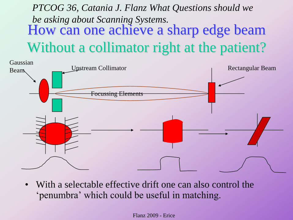
How can one achieve a sharp edge beam
Without a collimator right at the patient?
• With a selectable effective drift one can also control the „penumbra‟ which could be useful in matching.
Upstream CollimatorGaussian
Beam
Focussing Elements
Rectangular Beam
PTCOG 36, Catania J. Flanz What Questions should we
be asking about Scanning Systems.
Flanz 2009 - Erice
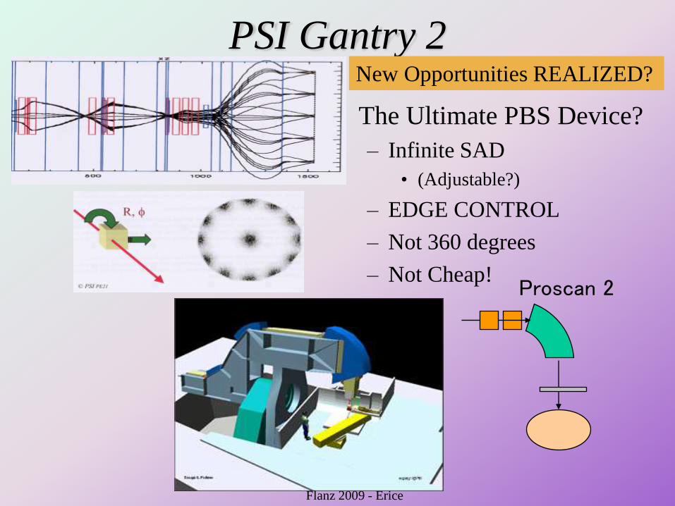
PSI Gantry 2
• The Ultimate PBS Device?
– Infinite SAD
• (Adjustable?)
– EDGE CONTROL
– Not 360 degrees
– Not Cheap!Proscan 2
Flanz 2009 - Erice
New Opportunities REALIZED?
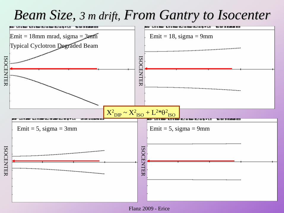
Beam Size, 3 m drift, From Gantry to Isocenter
Emit = 18mm mrad, sigma = 3mm Emit = 18, sigma = 9mm
Emit = 5, sigma = 3mm Emit = 5, sigma = 9mm
ISO
CE
NT
ER
ISO
CE
NT
ER
ISO
CE
NT
ER
ISO
CE
NT
ER
Typical Cyclotron Degraded Beam
X2DIP ~ X2
ISO + L2*2ISO
Flanz 2009 - Erice
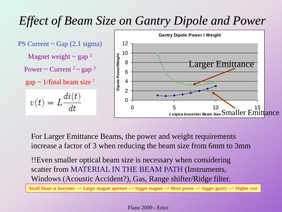
Effect of Beam Size on Gantry Dipole and PowerGantry Dipole Power / Weight
0
2
4
6
8
10
12
0 5 10 151 sigma Isocenter Beam Size
Dip
ole
Po
wer/
Weig
ht
PS Current ~ Gap (2.1 sigma)
Magnet weight ~ gap 2
Power ~ Current 2 ~ gap 2
gap ~ 1/final beam size ?
Smaller Emittance
Larger Emittance
For Larger Emittance Beams, the power and weight requirements
increase a factor of 3 when reducing the beam size from 6mm to 3mm
!!Even smaller optical beam size is necessary when considering
scatter from MATERIAL IN THE BEAM PATH (Instruments,
Windows (Acoustic Accident?), Gas, Range shifter/Ridge filter. Small Beam at Isocenter --> Larger magnet aperture --> bigger magnet --> More power --> bigger gantry --> Higher cost
Flanz 2009 - Erice
No time to discuss
• Hypofractionation (Conformality or
Radiobiology?)
• Organ Motion
– Gating
– Tracking (Position AND Range)
• Instrumentation (What is needed?)
• Imaging (What is needed?)
Flanz 2009 - Erice
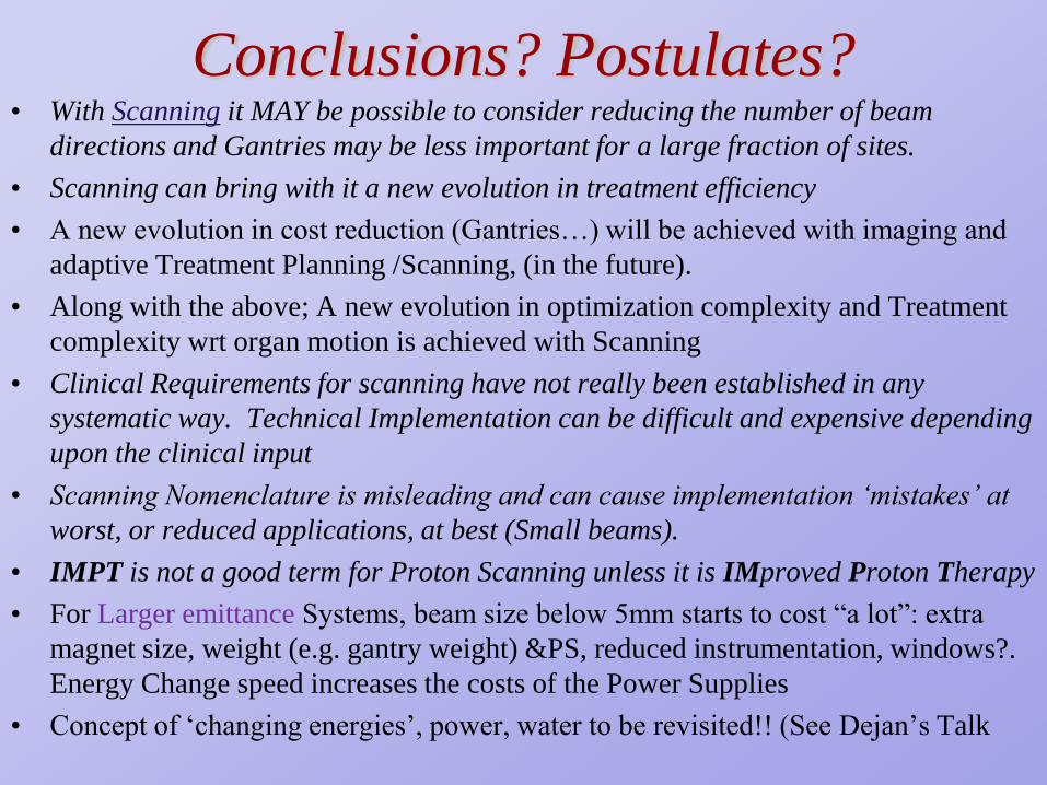
Conclusions? Postulates?• With Scanning it MAY be possible to consider reducing the number of beam
directions and Gantries may be less important for a large fraction of sites.
• Scanning can bring with it a new evolution in treatment efficiency
• A new evolution in cost reduction (Gantries…) will be achieved with imaging and
adaptive Treatment Planning /Scanning, (in the future).
• Along with the above; A new evolution in optimization complexity and Treatment
complexity wrt organ motion is achieved with Scanning
• Clinical Requirements for scanning have not really been established in any
systematic way. Technical Implementation can be difficult and expensive depending
upon the clinical input
• Scanning Nomenclature is misleading and can cause implementation „mistakes‟ at
worst, or reduced applications, at best (Small beams).
• IMPT is not a good term for Proton Scanning unless it is IMproved Proton Therapy
• For Larger emittance Systems, beam size below 5mm starts to cost “a lot”: extra
magnet size, weight (e.g. gantry weight) &PS, reduced instrumentation, windows?.
Energy Change speed increases the costs of the Power Supplies
• Concept of „changing energies‟, power, water to be revisited!! (See Dejan‟s Talk
Trap to Avoid
• Beam parameters will DRIVE beam
delivery modality.
– “Tell me what the machine can do so I can
simulate the modality.”
• OR Vice- Versa
– “Do simulations to help optimize treatments
and tell me what the machine should do”
Flanz 2009 - Erice

44
Flanz 2009 - Erice
44
The Francis H. Burr Proton Therapy Center
Thank You !