behaviour of bentonite suspensions in non-aqueous...
TRANSCRIPT

BEHAVIOUR OF BENTONITE SUSPENSIONS IN NON-AQUEOUS MEDIA
A THESIS SUBMITTED TO
THE GRADUATE SCHOOL OF NATURAL AND APPLIED SCIENCES
OF
MIDDLE EAST TECHNICAL UNIVERSITY
BY
TOGAN USKARCI
IN PARTIAL FULLFILLMENT OF THE REQUIREMENTS
FOR
THE DEGREE OF MASTER OF SCIENCE
IN
MINING ENGINEERING
APRIL 2006

Approval of the Graduate School of Natural and Applied Sciences
Prof. Dr. Canan Özgen Director
I certify that this thesis satisfies all the requirements as a thesis for the degree of Master of Science.
Prof. Dr. Ümit Atalay
Head of Department This is to certify that we have read this thesis and that in our opinion it is fully adequate, in scope and quality, as a thesis for the degree of Master of Science.
Prof. Dr. Ali İhsan Arol
Supervisor
Examining Committee Members Prof. Dr. Gülhan Özbayoğlu (METU,MINE)
Prof.Dr. Çetin Hoşten (METU,MINE)
Prof.Dr. Ümit Atalay (METU,MINE)
Prof.Dr. Ali İhsan Arol (METU,MINE)
Assist. Prof. Dr. Evren Özbayoğlu (METU,PETE)
iii
I hereby declare that all information in this document has been obtained and presented in accordance with academic rules and ethical conduct. I also declare that, as required by these rules and conduct, I have fully cited and referenced all material and results that are not original to this work. Name, Last name: Togan Uskarcı
Signature :

iv
ABSTRACT
BEHAVIOUR OF BENTONITE SUSPENSIONS IN NON-AQUEOUS MEDIA
Uskarcı,Togan
M.Sc., Department of Mining Engineering
Supervisor: Prof. Dr. Ali İhsan Arol
April 2006, 110 pages
Bentonite is a smectite type clay mineral and swells in water. In this
thesis, the effect of acetone, methyl-ethyl ketone, n-hexane on the
properties of bentonite was determined by thermal analysis and water
absorption tests. The tests indicated no significant change with treating
bentonite with organic liquids.
Because of the swelling property, only small amount of bentonite can be
suspended in water. This may limit certain applications of bentonite. In
this thesis, feasibility of suspending large quantities of bentonite in a
non-aqueous media was studied. The concentrations for a pumpable high
solid bentonite slurry were determined. As aqueous slurry showed
pumpable properties up to 30-35 pounds/barrel, this concentration was

v
as high as 125-150 pounds/barrel for acetone, 175-200 pounds/barrel for
methyl-ethyl ketone and 325-350 pounds/barrel for n-hexane.
Bentonite deposite has a complicated composition, containing free silica
minerals, such as quartz, cristobalite, and opal; silicate minerals, such as
feldspar, mica, and zeolite; carbonates or sulfates of alkaline earth
metals, such as calcite, dolomite, and gypsum; and, in addition, iron
compounds and humus. As mined it is primarily broken and dried and
then pulverized by means of an attrition grinding machine. In this study
dispersion of raw bentonite by high shear blending and shaking forces in
the presence of acetone, methyl-ethyl ketone and n-hexane and
eliminating the non-clay impurities by screening were studied.
Many attempts have been made to provide a bentonite composition
retaining the full swelling properties of the bentonite by the addition of
non-aqueous liquids for obtaining a flexible waterproofing sheet. In this
research the possible method for deposition of bentonite in a sponge by
saturating the sponge with bentonite using organic liquids was
investigated.
Keywords: Bentonite, clay, non-aqueous, suspension, montmorillonite, swelling
vi
ÖZ
BENTONİT SÜSPANSİYONLARININ SU DIŞI SIVILARDA DAVRANIŞI
Uskarcı,Togan
Yüksek Lisans, Maden Mühendisliği Bölümü
Tez Yöneticisi: Prof.Dr. Ali İhsan Arol
Nisan 2006 , 110 sayfa
Bentonit suda şişme özelliğine sahip, semektit türü bir kil mineralidir. Bu
tezde aseton, metil-etil keton ve n-hekzanin bentonite üzerindeki etkileri
termal analiz ve su emme deneyleriyle belirlenmiştir. Deney sonuçlari,
bentonitin özelliklerinin organik sıvılarla değişmediğini göstermiştir.
Şişme özelliğinden dolayı, sulu süspansiyonlarda çok az miktarlarda
bentonit kullanılmaktadır. Bu da, bentonitin kullanım alanlarını
sınırlamaktadır. Bu tezde bol miktarda bentonite içeren süspansiyonların
su dışı ortamlarda eldesi incelenmiştir. Pompalanabilir bentonit
süspansiyonlarının konsantrasyonları belirlenmiştir. Bu konsantrasyon
sulu süspansiyonda 30-35 pound/varil’ken, aseton süspansiyonu için 125-
150 pound/varil, metil-etil keton için 150-175 pound/varil n-hekzan
süspansiyonu için 325-350 pound/varil olarak bulunmuştur.

vii
Bentonite maden yatağı serbest kuvartz, kristobalit, opal gibi silisli
mineralleri, feldispat, mika, zeolit gibi silikatlı mineralleri, kalsit dolomite,
jips gibi alkali toprak metallerini karbonat ve sülfatlarından ve ek olarak
demir bileşimleri ve humusu kapsayan karmaşık bir yapıya sahiptir.
Cevher çıkardıldıktan sonar ilk once kırılır ve kurutulur ve daha sonra
öğütme aletleriyle öğütülür. Bu çalışmada ham bentonitin yüksek
makaslamayla karıştırılması ve salllama kuvvetleriyle ayrıştırılması ve
eleme suretiyle kil dışı safsızlıkların giderilmesi çalışılmıştır.
Bentonite su dışı sıvıların eklenmesiyle, bentonitin şişme özelleklerini
koruyarak, esnek su geçirmez tabaka elde etmek için bir çok çalışma
yapılmıştır. Bu çalışmada bentonitin organik sıvı yardımıyla sünger içine
depolanmasıyla böyle bir yapı eldesi incelenmiştir.
Anahtar Kelimeler: Bentonit, kil, süspansiyon, montmorillonit, şişme

viii
ACKNOWLEDGEMENTS
I want to express my sincerest and endless appreciation to my advisor
Prof. Dr. Ali İhsan Arol for his kind supervision, guidance, suggestions,
comments, help and friendly attitude throughout this study.
I would also like to thank to Assist. Prof. Dr. Evren Özbayoğlu for his
friendly attitude, guidance and support.
I gratefully acknowledge to METU Mining Engineering Department
academic staff and technical staff for their kindness, friendly attitude and
technical support.
I would also like to express my thanks to all my friends for their help,
comments, encouragement throughout the hard times in the study and
especially for their kindly smile to me.
Finally, my endless and deepest thanks and love would go to my parents
and my brother. All the beauties, values and happiness they bring to my
life and the love they give me without expecting something in return
make me feel myself as the luckiest person in the world. Without them
this thesis would have never ended.

ix
TABLE OF CONTENTS
PLAGIARISM………………………………………………………………………………. iii
ABSTRACT………………………………………………………………………………….. iv
ÖZ……………………………………………………………………………………………… vi
ACKNOWLEDGEMENTS………………………………………………………………… viii
TABLE OF CONTENTS………………………………………………………………….. ix
LIST OF TABLES…………………………………………………………………………. xii
LIST OF FIGURES……………………………………………………………………….. xv
CHAPTER
1. INTRODUCTION……………………………………………………………….. 1
2. LITERATURE SURVEY………….……………………………………………. 5
2.1. Chemistry and Mineralogy of Clays……………………………… 5
2.1.1 The Structures of Clays…………….………………..……….. 5
2.1.2 The Structures of Smectites……………………………..…. 7
2.2 Electrochemical Properties of Clays………………………………. 10
2.2.1 Electrical Double Layer………………………………………… 10
2.2.1.1 Interparticle Double Layer Repulsion………. 13
2.2.1.2 Van der Waals Attractive Forces……………... 13
2.2.1.3. Total Interaction Energy…………………….... 14
2.2.2 Particle Association in Clay Suspensions……………….. 15
2.3 Adsorption Characteristics of Clays………………………………. 18
2.3.1The Mechanism of Adsorption of Organic Compounds
Inside the Interlayer Space of Swelling Clay Minerals 21

x
2.3.1.1 Complexes with Ketones………………………… 30
2.3.1.2 Complexes with Aliphatic and Aromatic
Hydrocarbons……………………………………………………. 32
2.4 Rheological Behaviour of Clays…………………………………….. 34
2.6 Bentonite Slurries……………………………………………………… 39
2.7 Purification of Bentonite…………………………………………….. 44
2.8 Waterproofing Bentonite Material…………………………………. 47
3. MATERIALS AND METHODS …………………………….………………… 51
3.1 Materials …………………………………………………………………… 51
3.2 Methods……………………………………………………………………. 53
3.2.1 Thermal Analysis………………………………………………… 53
3.2.3 Water Absorption Tests…………………………….…………. 54
3.2.2 Rheological Behaviour Analysis………………………..…… 57
3.2.4 Purification Tests………………………………………………… 57
3.2.4.1 Purification of Bentonite by Using Non-
Aqueous Media……………………………………………….… 57
3.2.4.2 Purification of Artificially Contaminated
Bentonite by Using Non-Aqueous Media …………….. 59
3.2.5 Bentonite Absorption of Sponge Tests…………………… 60
4 RESULTS AND DISCUSSIONS……………………………………………… 62

xi
4.1 1 Effect of Organic Liquids on the Thermal Characteristics
of Bentonite..................................................................…… 62
4.2 Effect of Organic Liquids on the Water Absorption
Characteristics of Bentonite………………………………………………. 65
4.3 Rheological Behavior of Bentonite in Aqueous and Non-
Aqueous Media ……………………………………………………………….. 66
4.4. Purification of Bentonite…………………………………………….. 78
4.4.1 Purification of Bentonite by Using Non-
Aqueous Media……………………………………………….… 78
4.4.2 Purification of Artificially Contaminated
Bentonite by Using Non-Aqueous Media …………….. 84
4.5 Bentonite Absorption Capacity for Sponge…………………….. 86
5. CONCLUSIONS…………………………………………………….…………… 91
REFERENCES………………………………………………………….………………….. 92
APPENDICES………………………………………………………………………………… 96

xii
LIST OF TABLES
TABLES 1. Chemical Composition of the Tokat Resadiye Bentonite............... 51
2. Water absorption of non-aqueous liquid treated bentonite
samples……………………………………………………………………………………. 65
3. Shear Stresses (lbf/100 ft2) of different bentonite concentrations
for aqueous bentonite slurries at different shear rates …………………. 67
4. Shear Stresses (lbf/100 ft2) of different bentonite concentrations
for acetone bentonite slurries at different shear rates..............…… 69
5. Shear Stresses (lbf/100 ft2) of different bentonite concentrations
for methyl-ethyl ketone bentonite slurries at different shear rates.... 71
6. Shear Stresses (lbf/100 ft2) of different bentonite concentrations
for n-hexane bentonite slurries at different shear rates ……………….. 73
7. Critical Yield Point-Plastic Point Concentrations for a pumpable
Bentonite Slurry……………………………………………………………………….. 78
8. Dispersion and Water Absorption of Bentonite
Blending time: 2 minutes…………………………………………………………… 79
9. Dispersion and Water Absorption of Bentonite Blending time: 4
minutes....................................................................................... 81
10. Dispersion and Water Absorption of Bentonite Shaking time: 5
minutes....................................................................................... 83

xiii
11. Dispersion and Water Absorption Tests for artificially
contaminated Bentonite. Shaking time: 5 minutes........................... 85
12. Bentonite absorption of Sponge............................................... 87
13. Volume of the Sponges........................................................... 88
14. % Void Volume Bentonite Absorbed......................................... 89
A1. Weights of Bentonite with wet filter for water absorption tests... 96
A2. Weights dry filter papers for water absorption tests……………….. 97
A3. Weights of Bentonite for 50 g/200 ml at 2 and 4 minutes
purification of bentonite experiments............................................. 97
A4. Weights of Bentonite with wet filter papers for 2 and 4
purification of bentonite experiments............................................. 98
A5. Weights dry filter papers for 2 and 4 minutes purification of
bentonite experiments.................................................................. 98
A6. Weights of Bentonite for 50 g/200 ml at 5 minutes shaking
experiments................................................................................. 99
A7. Weights of Bentonite with wet filter papers 5 minutes shaking
experiments................................................................................. 99
A8. Weights dry filter papers for 5 minute shaking experiments...... 99
A9. Weights of Bentonite with wet filter papers for 5 minutes
shaking experiments with gangue mineral...................................... 100
A10. Weights of dry filter papers for 5 minutes shaking experiments
with gangue mineral..................................................................... 100

xiv
A11. Specifications for Acetone…………………………………………………… 102
A12. Specifications for Methyl Ethyl Ketone.................................... 102
A13. Specifications for N-Hexane................................................... 103

xv
LIST OF FIGURES
FIGURES 1. A structural scheme of Si-Tetrahedron ………………..……………… 6
2. A structural scheme of Al-Octohedral …………………………………. 7
3. The layer structure of montmorillonite according to Hofmann,
Endell, Wilm, Marshall, Maegdefrau and Hendricks ……………….……. 9
4. (a) The structure of a diffuse electrical double layer at the surface
of a clay particle or silicate layer; and (b) distribution of the
concentration of cations (n+) and anions (n-) with distance from the
surface for a symmetrical electrolyte with a bulk concentration of no 11
5. Total interaction energy Vt for parallel flat plates as a function of
particle plate separation ………………………………………………………... 14
6. Modes of particle association in clay suspensions: a) dispersed; b)
face-to-face (FF); c) edge-to-face (EF); and d) edge-to-edge (EE) 16
7. Alternative models describing the association of clay particles
a) edge-to-edge (EE) ribbons; and b) ‘Bandermodel’ …………….……… 17
8. Representation of a three-layer expanding clay lattice. ………… 18
9. Schematic diagram of straight column model a) and zigzag
column model b), for the arrangement of layers in montmorillonite
aqueous suspensions ...........…………………………………………….……… 20

xvi
10. Relationship between layer charge characteristics of
montmorillonite a) polar molecules in montmorillonite b) mainly
non-polar groups with some polar groups in montmorillonite ……….. 22
11. Consistency curves for four different types of flow …..………….. 35
12. Typical flow curves for concentrated thixotropic clay
suspensions. 1. initial flow curve; 2. flow curve after mixing; and 3.
Thixotropic loop ………………………………………………….…………………… 38
13. TGA equipment …………….………………………………………….……. 54
14. Water absorption apparatus …………………………………..………….. 55
15. Wet screen shaking mechanism for purification of bentonite
using non-aqueous media…………………………………………………………. 59
16. TGA results for untreated bentonite ………………………….…………. 63
17. TGA results for Acetone treated bentonite …………………………… 63
18. TGA results for methyl-ethyl ketone treated bentonite ….……… 64
19. TGA results for n-hexane treated bentonite ………………………. 64
20. Water absorption of non-aqueous liquid treated bentonite
samples…………………………………………………………………………………….. 66
21. Rheological behaviour of aqueous bentonite slurry at different
concentration levels (a) 10 g/350 ml (b) 15 g/ 350 ml (c)30 g/
(d)35 g/350 ml (e)40 g/350 ml (f)45 g/350 ml …………………………….. 68

xvii
22. Rheological behaviour of acetone bentonite slurry at different
concentration levels (a) 20 g/ 350 ml (b) 30 g/350 ml (c) 40 g/350
ml, (d) 50 g/350 ml (e) 60 g/350 ml (f) 70 g/350 ml (g) 80 g/350
ml, (h) 150 g/350 ml (i)250 g/350 ml………………..……………..……….. 70
23. Rheological behaviour of Methyl-ethyl ketone bentonite slurry at
different concentration levels (a) 125 g/350 ml (b) 150 g/350 ml (c)
175 g/350 ml (d) 200 g/350 ml (e) 225 g/350 ml (f) 250 g/350 ml 72
24. Rheological behaviour n-hexane bentonite slurry at different
concentration levels (a) 125 g/350 (b) 150 g/350 ml(c) 175 g/350
ml (d) 200 g/350 ml (e) 225 g/350 ml (f) 275 g/350 ml (g) 325
g/350 (h) 350 g/350 ml.(i) 425 g/350 ml...……………………………….. 73
25. Yield Points-Plastic Viscosities of aqueous bentonite slurries at
different bentonite concentrations …………………………….………………. 75
26. Yield Points-Plastic Viscosities of acetone bentonite slurries at
different bentonite concentrations ………………………………………………. 76
27. Yield Points-Plastic Viscosities of methyl ethyl ketone bentonite
slurries at different bentonite concentrations ……………….…………….. 76
28. Yield Points-Plastic Viscosities of n-hexane bentonite slurries at
different bentonite concentrations ……………………………………..……… 77
29. Water Absorption tests of -100# and +100 fractions of
bentonite dispersed in organic solvents followed by screening.
Blending time: 2 minutes………………………………………………………….. 80

xviii
30. Water Absorption tests of -100# and +100 fractions of
bentonite dispersed in organic solvents followed by screening.
Blending time: 4 minutes………………………………..………………………… 82
31. Water Absorption tests of -100# and +100 fractions of
bentonite dispersed in organic solvents followed by screening.
Shaking time: 5 minutes…………………………………………….…………….. 84
32. Water Absorption tests of -100# and +100 fractions of
artificially contaminated bentonite dispersed in organic solvents
followed by screening. Shaking time: 5 minutes ………………………. 86
33. Bentonite absorption of sponge ……………………………………...…. 88
34. % Void Volume bentonite absorbed in the sponge Bentonite
absorption of sponge ………………………………………………………………. 90
A1. Water Absorption of filter paper.…………………………………………. 101

1
CHAPTER 1
INTRODUCTION
Bentonite is an important commercial mineral mainly composed of
smectite group of clay minerals. It has wide application areas such as
drilling mud, or drilling gel, the metal casting industry, foundry molding
sand, cat litter, feed pelletizing industry, sealing freshwater ponds,
irrigation ditches, reservoirs, sewage and industrial water lagoons,
grouting permeable ground in detergents, fungicides, sprays, cleansers,
polishes, ceramic, paper, cosmetics and medicines, and applications
where its unique bonding, suspending or gellant properties are required.
Bentonite is highly colloidal and readily swells in water to form viscous,
thixotropic gels which render these clays useful as viscosity builders in
the foregoing and in many additional industries and applications. As with
most minerals, however, these powders are difficult and expensive to
handle. They also are subject to considerable "dusting", i.e. evolution of
dust during handling, so that they can, in some cases, cause
environmental problems, and even health risks. To minimize these
problems, many minerals are sold by the manufacturer as high solids
aqueous slurries. Such high solids slurries can be easily stored, shipped,
transferred, e.g. pumped and metered, with significantly less capital
expenditures and many fewer problems than are associated with
powdered minerals, as mentioned above. In most applications,
nevertheless, it is not economical to ship smectite clay slurries because of
the large quantity of water present in shippable slurries. It has not
heretofore been practical to produce and ship high solids slurries by the
usual methods since smectites are indeed good viscosifiers. In general,
only about 8% -10% solids slurries of good quality swelling smectite can
be produced in water. Indeed, at solids contents greater than about 8%,

2
the viscosities of the slurries can become so high that they cannot readily
be pumped by conventional equipment and gelling upon standing
becomes a problem. At higher solids it becomes virtually impossible to
form a uniform paste without special equipment. Thus, there is a need
for slurries containing substantially greater than 8% by weight of
smectite clay, which have viscosities low enough to allow pumping. In
addition, the more such clay which can be incorporated into the slurry
the more economical it is to ship the clay since the total weight of the
slurry will include less fluid weight [1].
Bentonite deposit has a complicated composition mainly formed of
smectites and containing free silica minerals, such as quartz, alpha-
cristobalite, and opal; silicate minerals, such as feldspar, mica, and
zeolite; carbonates or sulfates of alkaline earth metals, such as calcite,
dolomite, and gypsum; and, in addition, iron compounds and humus.
Since bentonite ore mined from bentonite deposit usually has a water
content of 15 to 35%, it is primarily broken and dried in the sun or hot
air to obtain bentonite ore having a water content of 5 to 10%. The dried
bentonite ore is pulverized by means of an attrition grinding machine,
such as a centrifugal roller mill, or an impact mill, such as a hammer mill.
As stated above, bentonite for these uses basically has a composition
based on the natural bentonite deposit, containing much non-clay
substances. Purified bentonite powder, which is obtained by dispersing
bentonite in water, removing unfavorable non-clay substances by
spontaneous sedimentation or centrifugal separation, subjecting a
suspension of the bentonite to shearing, attrition and impact forces in a
homogenizer of the type and drying the resulting purified bentonite sol
by evaporation, is used as a rheological adjuster for aqueous coatings,
aqueous emulsions, or the like aqueous colloidal dispersion products. [2].

3
Many attempts have been made to provide a bentonite composition
having sufficient cohesiveness and structural integrity to provide a
modeling clay-like or putty-like consistency. Such bentonite compositions
can be in a paste or putty-like form for handleability so that a desired
quantity can be applied in a selected location for water seepage control.
[3]. Such waterproofing material finds wide applicability in construction
industry, the waterproofing surfaces such as soil, plaza decks,
subterranean foundation surfaces and the like in the formation of
waterproofed construction areas; soil structure, such as lagoons; and
hazardous or toxic waste containment areas the penetration of water and
hazardous or toxic materials into the earth, and to provide lagoons,
ponds and other water containment areas [4].
Organic solvent-bentonite mixtures can be important for three
standpoints: production of a pumpable high concentration bentonite
slurry, beneficiation (purification) of bentonite of lesser quality,
deposition of bentonite in a porous structure.
This research undertaken during the course of this thesis aimed at
determining the conditions under which the aforementioned objectives
could be achieved using three organic solvents; acetone, methyl-ethyl-
ketone and n-hexane. Thermal analysis studied for investigating thermal
properties of the bentonite samples treated with acetone, methyl-ethyl
ketone, n-hexane and to determine the differences of the thermal
properties of the samples. The water adsorption characteristics of
bentonite samples treated with organic liquids and untreated bentonite
sample were determined to investigate the effect of organic liquids on
the water absorption of bentonite. Three non-aqueous organic liquids
were tested as high-bentonite slurry for low viscosity and effective usage
for applications and compared with aqueous slurry. In the beneficiation
of clay a new method can be proposed by treating the raw bentonite clay

4
in a organic liquid slurry without grinding, just exposing the high-solid
organic-bentonite slurry to shaking or high shear blending and purifying
the bentonite ore by eliminating the non-clay impurities. The organic
liquid might be recovered in a closed circuit process. The deposition of
bentonite in industrial sponge can be easily done with the aid of a high
solid content organic liquid bentonite slurry. The final product can find
many industrial applications as waterproofing bentonite sheets for
industrial applications.

5
CHAPTER 2
LITERATURE SURVEY
2.1 Chemistry and Mineralogy of Clays
2.1.1 The Structures of Clays
Mineralogists use the term "clay minerals" for a group of hydrous layered
magnesium- or alumino-silicates (phyllosilicates). In many of these
minerals various metallic cations, such as lithium, magnesium, and
aluminum, act as proxy wholly or in part for the magnesium, aluminum,
or silicon, respectively, with alkali metal and alkaline earth metal cations
present as exchangeable cations. Iron (di- or trivalent) is also a common
substituent of aluminum and magnesium. Each magnesium- or alumino-
phyllosilicate is essentially composed of two types of sheets, octahedral
and tetrahedral, designated O and T, respectively. Each sheet is
composed of planes of atoms, arranged one above the other, a plane of
hydroxyls and/or oxygens above a plane of aluminums and/or
magnesiums or silicons, the latter above another plane of hydroxyls
and/or oxygens, and so on. Variations among clay minerals and the
differences in their physical and chemical properties arise from the
various combinations of octahedral and tetrahedral sheets and the
electrostatic effects that chemical substitutions have on the units [5].
A continuous linkage of SiO4 tetrahedra as illustrated in Figure 1 through
sharing of three O atoms with three adjacent tetrahedra produces a
sheet with a planar network. In such a sheet the tetrahedral silica groups
are arranged in the form of a hexagonal network, which is repeated
indefinitely to form a phyllosilicate with the composition [Si4O10]4-. A side
view of the tetrahedral sheet shows that it is composed of three parallel

atomic planes, which are composed of oxygens, silicons, and oxygens,
respectively. The tetrahedra are arranged so that all of their apices point
in the same direction with their bases in the same plane. The oxygens
form an open hexagonal network in this plane, often referred to as the
hexagonal or perforated oxygen plane (or O-plane). In reality the silica
tetrahedra are slightly distorted, and consequently, the cavities bordered
by six oxygens are ditrigonal rather than hexagonal. This perforated
oxygen plane is an important contributor to the surface properties of the
clay minerals. Each oxygen atom is covalently bound to two silicons, thus
becoming the active component of an Si-O-Si (siloxane) group [5].
Figure. 1 A structural scheme of Si-Tetrahedron [6].
An Octahedral sheet is obtained through condensation of single
Mg(OH)6-4 or Al(0H)6
-3 as can be seen in Figure 2. Each O atom is shared
by three octahedra, but two octahedra can share only two neighboring O
atoms. In this sheet the octahedral groups are arranged to form a
hexagonal network, which is repeated indefinitely to form an [Mg6012]12-
or [Al4O12]12- layer. The minerals brucite, Mg(OH)2, and gibbsite, AI(OH)3,
have such sheet structures. A side view of the octahedral sheet shows 6
that it is closely packed, being composed of a dense hexagonal plane of
Mg of Al atoms sandwiched between two dense hexagonal "hydroxyl
planes." All the octahedra are filled with Mg atoms in brucite or its clay
derivatives, but only two thirds of the octahedra are filled with Al atoms
in gibbsite and its derivatives [5].
Figure. 2 A structural scheme of Al-Octohedral [6].
2.1.2 The Structures of Smectites
Bentonite is defined as a clay composed dominantly of a smectite clay
mineral and whose properties are a consequence of this mineral
component regardless of its mode of origin. Some bentonites are
hydrothermal alteration products of igneous rocks, rather than altered
ash. Commercial production of bentonite began in the United States in
the 1920s. The unique physical properties of this clay and its widespread
use were powerful incentives for much clay mineral research. Bentonites
were not recognized and developed in Europe until the 1930s, some
years after the development of the Wyoming deposits. The widespread
commercial use of bentonite has caused a world-wide search for this 7

8
clay, and today, it is extensively mined in many countries, including the
United Kingdom, Germany, Italy, Greece, India, Japan, and Russia [7].
Minerals of the smectite consist of TOT layers. They differ from talc and
pyrophyllite in that a small fraction of the tetrahedral Si atoms is
isomorphically substituted by Al and/or a fraction of the octahedral atoms
(Al or Mg) is substituted by atoms of lower oxidation number. The
resulting charge deficiency is balanced by hydrated cations, mainly K, Na,
Ca, and Mg, of which more than 80% is located between the parallel clay
layers as shown in Figure 3. These ions are hydrated due to the fact that,
in nature, smectites are formed in aqueous environments. Because they
are hydrated, these cations are only loosely held by the negatively
charged clay layers. In very dilute aqueous suspensions, Li- and Na-
smectites dissociate into large negatively charged silicate layers and small
cationic species and exhibit many properties of a polyelectrolyte.
Smectites saturated with other cations dissociate in aqueous suspensions
into exchangeable cations and tactoids, which are composed of several
parallel TOT layers, held together by electrostatic forces by some of the
exchangeable cations that remain in the interlayer space [5]. Tactoids
are spindle shaped regions in a sol in which the particle concentration is
higher than the bulk of the sol. Occasionally, they separate as a bottom
sediment. They are spontaneously formed in some sols of plate- or rod
like particles. In tactoids, the particles are oriented parallel to each other
at distances of the order of 100 A. Tactoid formation is a special case of
coacervation, that is, the separation of a sol in two liquid phases of
different concentration [8]. Because they dissociate, the original cations
are exchangeable by other inorganic and organic cations. The negative
charge per unit cell from isomorphic substitution ranges between 0.5 and
1.3 electronic charges. In smectite tactoids electrostatic forces keep the
layers together. Parallel TOT layers are packed one above the other and
the exchangeable hydrated cations are located between the layers [5].

Figure. 3. The layer structure of montmorillonite according to Hofmann,
Endell, Wilm, Marshall, Maegdefrau and Hendricks [9].
Water and polar organic molecules are attracted by the exchangeable
cations and may intercalate between the layers, causing the structure to
expand in the direction perpendicular to the layers. The interlayer space
between the TOT layers, obtained as a result of the expansion of the
clay, has special chemical properties. The swelling of this space depends
on several factors, such as the exchangeable cation, the humidity of the
environment and the vapor pressure, and the temperature. The basal
spacing may vary from 1000 pm (for dry smectites) to more than 2000
pm. In dilute aqueous suspensions of Li- and Na-smectites, separations
between layers larger than 4,000 pm have been identified [5].
9

2.2 Electrochemical Properties of Clays
2.2.1 Electrical Double Layer
Clay particles in suspension owe their stability to mutual repulsion when
their intersecting diffuse electrical double layers interact on approach. In
clay-water systems, a double layer is made up of the negative surface
charge and the balancing cation charge as seen in Figure 4. In the case
of clay particles, the negative charge is a consequence of imperfections
within the interior of the crystal lattice. Clay colloids possess a constant
charge, because its surface charge arises from isomorphous substitution
[10].
The counter-ions are electrostatically attracted by the oppositely charged
surface as illustrated in Figure 4a. These ions have a tendency to diffuse
away from the surface to the bulk solution where the concentration is
lower. Therefore, the concentration of the counter-ions near the particle
surface is high, and it decreases with increasing distance from the
surface. The diffuse layer does not only consist of an excess of ions of
opposite sign; there is a deficiency of ions of the same sign near the
surface, since the ions are electrostatically repelled by the surface. This
diffuse character of the counter-ion atmosphere was recognized by Gouy
[11] [12] and Chapman [13], who presented a theoretical treatment of
the counter-ion distribution. Their theory predicts an approximate
exponential decay of the electrical potential Ψ of the solution with
distance x from the plane surface. This is represented by the following
equation:
)(exp( 0 χκ−Ψ=Ψ (2-1)
10

where ψ0 is the surface potential and κ-1 the extension or thickness of the
double layer. The above expression is valid for a certain distance from
the charged surface, where the potential is relatively low and decreases
exponentially as can be seen in Figure 4b [10].
Figure. 4. (a) The structure of a diffuse electrical double layer at the
surface of a clay particle or silicate layer; and (b) distribution of the
concentration of cations (n+) and anions (n-) with distance from the
surface for a symmetrical electrolyte with a bulk concentration of no [10].
∑= n
iii zcF
TR22
01 εκ
(2-2)
where: F is the Faraday constant, ci the electrolyte concentration, zi the
valence of the ion, ε0 the dielectric constant of the medium, R the gas
constant (1 atm/mol K) and T the absolute temperature (K) [10].
The Gouy-Chapman theory leads to unrealistically large ion
concentrations at high potentials, since it assumes that the counterions
are point charges. To correct this, Stern [14] postulated the existence of
an adsorbed layer of finite sized counterions adjacent to the surface. The
potential in the Stern layer falls off linearly from its surface value (ψ0) to
11

the Stern potential (ψδ) after which it decays exponentially. The thickness
of the Stern layer has been estimated for different clay systems [15]. The
outer Helmholtz plane lies outside the Stern layer and marks the
boundary between the fixed and mobile part of the diffuse double layer,
and is called the plane of shear [16]. At this plane the potential is called
the zeta potential and in practice it is assumed that it is equal to the
Stern potential (ψδ) [10].
The edge of the clay particle is assumed to possess an electrical double
layer of a different nature to that of the flat surface described above.
This double layer is due to the adsorption of potential determining ions
on the broken bonds of the tetrahedral silica sheets and octahedral
alumina sheets. There is a strong possibility that in a neutral clay
suspension a positive double layer is created on the edge surfaces owing
to the exposed alumina sheet, whereby it may become more positive
with decreasing pH and its sign may be reversed with increasing pH.
Various studies indicate that the edges of clay particles are positively
charged at pH 7-8 and some data suggest that the edges are neutralized
at pH 6. The existence of positive sites on the edges have been
demonstrated by the addition of a negative gold sols to the clay-type
kaolinite, where the resulting electronmicrograph showed the gold
particles adsorbing only at the crystal edges [10].
A theoretical analysis of the interaction between colloidal particles has
been developed by Derjaguin and Landau [17] and Verwey and Overbeek
[18]. The fundamental feature of what is known as the DLVO Theory is
that this interaction is determined by a combination of the interparticle
double layer repulsion energy (VR) and the Van der Waals attractive
energy (VA). Colloidal stability may be explained by means of the
superposition of both energies [10].
12

13
2.2.1.1 Interparticle Double Layer Repulsion.
As two particles approach each other in suspension due to Brownian
motion, their diffuse double layers begin to interfere. Consequently, there
is a change in the distribution of ions surrounding both particles leading
to an increase of the free energy of the system. The amount of work
required to carry out those changes and to bring the particles from
infinite separation to a given distance is the repulsive energy or repulsive
potential [10].
The repulsive potential decreases exponentially with increasing particle
separation and the range of repulsion is considerably reduced with
electrolyte concentration. The DLVO theory assumes that the dispersed
particles are not hydrated and hence do not have an additional repulsive
force when two particles approach one another in aqueous solution. It
appears likely that for Na-montmorillonite, the total interaction between
the charged platelet surfaces should involve both short range repulsion
forces, due to partially bound hydrated cations and a longer range
repulsion due to hydrated counterions in the double layer [10].
2.2.1.2 Van der Waals Attractive Forces.
There are three types of intermolecular attraction that are recognised:
dipole-dipole interaction; induced dipole-dipole interaction and attractive
forces between non-polar molecules (London dispersion forces). The
London dispersion forces, which are due to the polarization of one
molecule by fluctuations in the charge distribution in the second
molecule, account for nearly all of the Van der Waals attraction in
colloidal systems [10].

2.2.1.3. Total Interaction Energy.
The net or total interaction energy Vt is the sum, of the repulsive
potential VR and attractive potential Va [10].
art VVV += (2-3)
A representation of Vr, Va and Vt as a function of the interplate separation
for low electrolyte concentrations (10-2 M).and high surface potentials
(>50 mV) is shown in Figure 5. Of significant importance is the
occurrence of a maximum energy (Vm) at intermediate distances, which is
considered as an energy barrier that the particles must overcome if they
are to ‘fall’ into the deep primary minimum at close distances and thus
come together. The height of Vm therefore determines the relative
stability of the system, and a value of 15-25 kT is normally required for
long-term stability. The term ∆Vb represents the barrier to redispersion.
At large interparticle separations, a secondary minimum may occur since
Vr falls off more rapidly with increasing distances than Va. Particle
coagulation taking place here is fairly reversible, since the minimum is
quite shallow [10].
Figure. 5 Total interaction energy Vt for parallel flat plates as a function
of particle plate separation [10].
14

15
The Na ions of the montmorillonite particles form diffuse ionic layers
surrounding them and create an electrostatic repulsion between the
particles. The addition of electrolytes in the system or an increase in
temperature will reduce Vm and so the clay particles will come into
contact with one another and agglomerate. The aggregation of particles
is known as coagulation or flocculation. The extent to which the particles
become flocculated depends upon the degree of compression of the
double layer, which is dominated by the concentration and valence of the
ions of opposite sign to the particle charge. Low electrolyte concentration
produces slow coagulation, which is retarded by a long-range repulsion.
At high electrolyte concentration attraction predominates at any particle
distance except at very close approach. In this case, particle
agglomeration occurs at a maximum rate and the process is called rapid
coagulation [10]. A more detailed description of the different modes of
particles association is discussed in section 2.2.2.
2.2.2 Particle Association in Clay Suspensions
If the concentration of clay is high enough, flocculation will cause the
formation of a continuous gel structure instead of individual flocs. The gel
structures build up slowly with time, as the particles orient themselves
towards positions of minimum free energy under the influence of
Brownian motion. The concentration of clay present in the system and
the salt content are decisive factors in the length of time required for a
gel to attain maximum strength. For Na-montmorillonite, this
concentration is usually above 3% (w/w) [10].
When a suspension of plate-like clay particles flocculates, three different
modes of particle association may occur: face-to-face (FF), edge-to-face
(EF) and edge- to-edge (EE). The electrical interaction energy for the
three types of association is governed by three different combinations of

the two double layers. Also, the rate of diffusion of the particles as they
approach each other in these three ways is not the same, and they may
not occur simultaneously or to the same extent when the clay suspension
is flocculated. The various modes of particle association are illustrated in
Figure 6. FF association leads to thicker and larger flakes, and EF and EE
association lead to three-dimensional voluminous ‘house-of-cards’
structures [10].
Figure.6. Modes of particle association in clay suspensions: a) dispersed;
b) face-to-face (FF); c) edge-to-face (EF); and d) edge-to-edge (EE)
[19].
Aggregation is best described by FF association, and refers to the
collapse of the diffuse double layers and the formation of aggregates of
parallel platelets spaced 20 A° or less apart. It decreases the gel strength
because it reduces the number of units available to build gel structures
and the surface available for particle interaction. The reverse for
aggregation is known as dispersion [10].
Flocculation of clay suspensions has been referred to as a consequence
of EF and EE association, responsible for the continuous gel-like structure
in the montmorillonite clay suspensions. However, other theories
describing the modes of interaction between montmorillonite particles
have been proposed. Including the above mentioned, they are:
16

• Mutual repulsion of the particles as a result of the interactions
between their double layers.
• Edge-to-edge association to form cross-linked ribbons, due to the
high repulsive potential between basal surfaces as shown in Figure
7a.
• Parallel association of plates, held together by crystalline water
between them.
Norrish [20] opposed Van Olphen’s theory of the house of cards
structure, suggesting that the gel structure in montmorillonite
suspensions was a consequence of the repulsive force caused between
the interacting double layers. Callaghan and Ottewill [21] actually
demonstrated that the gel properties of these dispersions are the
consequence of long-range interactions between the faces of the
particles. This theory is substantiated by the fact that the area of the
edge is small; therefore the electrostatic attraction between the edge and
face is small compared to the repulsion between the two faces when two
particles approach each other. These authors supported more the
existence of a band-like structure or the ‘Bander-model’ which was first
proposed by Weiss and Frank as shown in Figure 7b [10].
Figure 7. Alternative models describing the association of clay particles
a) edge-to-edge (EE) ribbons; and b) ‘Bandermodel’ [22].
17

2.3 Adsorption Characteristics of Clays
The interlayer space of an expanding TOT clay mineral lies between two
parallel silicate layers, bordered by two O planes, the oxygens belonging
to siloxane groups. The wettability and resulting structure of the
interlayer water are the outcome of (1) thermal motion of water
molecules in the environment of the mineral, (2) electrostatic attraction
forces between water molecules and the exchangeable cationic species,
and (3) attraction and dispersion forces between TOT layers [5].
Swelling is the process by which the clay mineral expands beyond its
original limit, which is 0.950 nm, as a result of adsorption of water into
the interlayer space. The uptake of water molecules is dependent on the
humidity and water vapor pressure in the environment of the mineral.
Since it causes a gradual expansion of the clay crystal along the c axis as
shown in Figure 8, it can be followed by x-ray diffraction. This expansion
can be monitored by the use of an adsorption isotherm. In most
published works swelling has been determined in air or in atmospheres
with various controlled humidities, but it has also been determined for
aqueous suspensions or under conditions where the vapor was obtained
from boiling water [5].
Figure. 9. Representation of a three-layer expanding clay lattice. [10].
18

19
A dry montmorillonite powder swells spontaneously when contacted with
water. The dry clay usually imbibes water and becomes a gel, and it can
be stirred up with more water to yield a suspension or sol. The swelling
of a clay is particularly spectacular in the case of montmorillonites. The
montmorillonite clay first takes up one to four monolayers of water
between the layers. This interlayer or intracrystalline swelling causes, at
most, a doubling of the volume of the dry clay. However, the swelling
process continues, and an amount of water is imbibed which is many
times the volume of the original clay. The additional swelling is a result of
the double layer repulsion between the surfaces of the individual
particles, which pushes them apart. Formalistically speaking, the swelling
may be called osmotic swelling since the water tends to equalize the high
concentration of ions between two particles, which are so close together
that their double layers overlap, and the low concentration of ions far
away from the particle surfaces in the bulk solution. Under suitable
confining conditions, a fluid pressure is created which is called the
osmotic or the swelling pressure of the clay. This pressure is a direct
measure of the balance of the forces between the particle faces [10].
Sometimes, the question is debated whether spontaneous swelling of the
clay finally leads to complete disintegration of the gel to a sol, or whether
the swelling is limited and stops as soon as a certain gel volume is
established. The reason that there is doubt about this question is
because it is difficult to perform an unambiguous experiment in which all
external forces are excluded, such as hydrodynamic convection forces
which tend to disperse the particles, or gravity forces which usually
operate against the further dispersion of the gel [10].
In principle, sol formation will be spontaneous only if at any particle
distance at any configuration of the particles in space, repulsion
predominates. In that case, the sol formation properly may be called

spontaneous. However, it seems that most clays-even certain sodium
montmorillonites are not spontaneously dispersed. Usually, at certain
particle separations and at certain particle configurations, attractive
forces cancel the repulsion, for example, van der Waals forces and the
important edge-to-face cross-linking forces. Entropy effects are probably
relatively small in these systems [10].
More recently, X-ray diffraction studies on Na-montmorillonite
suspensions were carried out to determine the alignment of the clay
particles upon swelling. For high Na-montmorillonite concentrations a
straight column model was used to describe the swelling behaviour
observed in Norrish’s work as can be seen in Figure 9a, but it failed to
describe the swelling at higher water content .A zig-zag column model
was found to agree with the swelling observed at both low and high
water content, where the layers swell not only longitudinally but also
laterally, assuming that the layer size is 1 µm as shown in Figure 9b [10].
Figure. 9. Schematic diagram of straight column model a) and zigzag
column model b), for the arrangement of layers in montmorillonite
aqueous suspensions [23].
Since uncharged polar organic molecules are adsorbed essentially by
replacement of the interlayer water, the behaviour of such molecules is
20

21
likewise strongly influenced by the exchangeable cation. Evidence is
accumulating to show that, at least at lower water contents, cation-dipole
interactions are of paramount importance in their effect on the
adsorption of polar organic species by clay minerals. [5].
2.3.1 The Mechanism of Adsorption of Organic Compounds
Inside the Interlayer Space of Swelling Clay Minerals
Many organic compounds with a dipole character are adsorbed on the
layer surfaces and probably also on the edge surfaces of a clay, in
analogy with the behavior of water. The adsorption energy of many of
these compounds is probably of a magnitude comparable with that of
water. They can displace adsorbed water from clays, but frequently the
organic compounds can be removed from the clay by washing with water
[8].
As in the case of the adsorption of water on clays, we do not know
exactly to what extent the polar groups of the organic molecules
associate with the counter-ions of the clay, and to what extent they are
hydrogen bonded with the oxygen surfaces. However, infrared absorption
indicates that the latter is less important [8].
Organic clay complexes with polar molecules can be prepared either by
contacting the dry clay with polar organic liquids or vapors, or by mixing
the polar liquid and a clay-water suspension [8].
When montmorillonite clays are treated with polar organic compounds,
such as alcohols, glycols, or amines, the organic molecules penetrate
between the layers and displace the interlayer water as illustrated in
Figure 10. The basal spacing of the complex depends on the size of the
organic molecules and on their orientation and packing geometry [8].

Figure. 10. Relationship between layer charge characteristics of
montmorillonite a) polar molecules in montmorillonite b) mainly non-polar
groups with some polar groups in montmorillonite [24].
Alternatively, when certain organic compounds are added to an
unknown mixture of clays, a basal spacing typical for the complex of that
compound will indicate the presence of montmorillonite in the mixture.
Ethylene glycol which gives a basal spacing of about 17 A with most
montmorillonites, is commonly used for this identification purpose [8].
When the clay surface becomes covered with polar molecules containing
a substantial proportion of hydrocarbon groups, the surface becomes
oleophilic, and in this condition, clay-oil dispersions can be prepared with
the treated clay. However, since the exchange cations are still present in
the complexes, they are usually rather sensitive to water. For example, a
pyridine complex of bentonite in the presence of water initially hydrates
stepwise, as shown by X-ray diffraction at low water concentrations, and
disperses completely when a large amount of water is added. Pyridinium
ion (or other organic cation) exchange complexes are not affected by
water. Exceptions are low molecular weight alkane ammonium complexes
22

23
of n-butylammonium) which show a spectacular interlayer swelling with
water [8].
The addition of a polar organic compound to a clay-water suspension
often causes flocculation of the clay. It has been pointed out before that
this effect is predicted by the Gouy theory. Sometimes, a peptizing effect
is observed, which might be explained by changes occurring in the Stern
layer. The effect of polar organic compounds on the stability of clay
suspensions is therefore rather unpredictable [8].
The Gouy theory shows that the "thickness" of the double layer
decreases when the dielectric constant of the medium is reduced. Such a
reduction may be achieved by the addition of water-miscible solvents,
such as alcohols or acetone, to the sol. Because of the compression of
the double layer, the range of particle repulsion is reduced and the size
of the energy barrier becomes smaller when the dielectric constant of the
medium decreases. Therefore, the theory explains the well-known fact
that most polar solvents enhance the flocculating power of an electrolyte
markedly. If a sol in water is till stable at a certain level of contamination
by an electrolyte, the addition of an organic solvent may induce
flocculation [8].
Exceptions to these rules do occur, and they must be explained by
considering secondary effects of the organic solvent on the double-layer
structure, as discussed hydration theory of stability [8].
The hydration theory of stability has been popular in colloid chemistry for
a long time. In this theory, the repulsion between particles is attributed
to the orientation of water dipoles in the electric field around the charged
particle. In such a "solvation shell," the degree of orientation of the
dipoles would gradually decrease with increasing distance from the

24
charged surface. When these diffuse hydration shells begin to interfere
when the particles approach each other, the mutual repulsion of the
oppositely oriented water dipoles around the colliding particles would
account for particle repulsion [8].
For hydrophilic colloids, the hydration repulsion was considered an
additional stability factor over and above the double-layer repulsion. The
high resistance of the hydrophilic colloids to added salt was attributed to
the presence of the extra stability factor. Also, in certain hydrophobic
sols, hydration repulsion was thought to contribute to the stability [8].
The argument against the hydration theory of stability is that the
orientation effect of the charged particles on the water dipoles can be
expected to be significant only up to a few water-molecule diameters
away from the surface. The energies involved are not sufficiently large to
affect the balance of the double-layer and van der Waals interaction
energies at the large distances from the surface where the fate of the
colliding particles is decided. Actually, many facts of colloid chemistry
appeared to be incompatible with the hydration theory of stability, which
is now obsolete. Nevertheless, hydration repulsion should not be entirely
disregarded. As mentioned previously, it is important in the short-range
interaction of particles. A thin layer of water a few molecules thick is
usually more or less strongly adsorbed at the particles surface; hence in
bringing the particles close together, the required work of desorption of
the water is manifested as a short-range repulsion [8].
The presence of a thick hydration shell around sol particles has also been
assumed to be the cause of gelation in hydrophilic sols and in certain
hydrophobic sols, such as alumina, silica, or clay sols. The rigidity of
these gels was thought to be the result of a rigidifying effect of the
charged particles on the water phase. However, the interparticle

25
distances in gels are often very large and beyond any sensible range of
hydration forces emanating from the surfaces. The alternative
explanation of gelation on the basis of skeleton formation by particle
linking is perfectly sensible and appears to supply a good basis for an
understanding of the mechanism of the creation as well as the
destruction of gels by the addition of small amounts of chemicals to the
liquid phase [8].
It should be mentioned that moderately long-range effects of charged
surfaces on certain properties of the water phase, such as the density or
the activation energy of viscous flow, are still claimed to exist [8].
The properties of the water in the first few monolayers which are
adsorbed at the surface may differ significantly from those of bulk water.
It is generally accepted that the dielectric constant of the adsorbed water
layers is much lower than that of free water. In the Stern model of the
double layer, the lowering of the dielectric constant in this region must
be taken into account in computing the capacity of the molecular
condenser and the Stern potential [8].
When alcohols or other organic polar solvents are added to the sol, these
compounds may be adsorbed on the surface in competition with water.
Therefore, they my affect the capacity of the Stern layer and hence the
Stern potential. In addition, the point of zero charge may be shifted, and
possibly even the van der Waals forces may be affected. Therefore, the
change of the composition of the medium may have several effects on
the constitution of the double layer and the particle-interaction energy.
An analysis of such effects in particular cases has explained why an
alcohol does not always have the flocculating effect predicted by the
Gouy theory as a consequence of the lowering of the dielectric constant
of the bulk liquid [8].

26
Most of the published data deals with montmorillonite and, to a smaller
extent, also with hectorite and other smectites. In the first half of the
twentieth century the principal techniques for the study of organo-
smectite interactions were chemical analysis, x-ray diffraction, and
differential thermal analysis. In 1934 Hoffmann showed that the basal
spacing of montmorillonite varied following treatment alcohol, acetone
and ether. Jordan measured by x-ray diffraction the basal spacings of
treated with n-alkylammonium montmorillonite (Wyoming bentonite)
treated with n-alkylammonium cations. He showed that the increase in
basal spacing with the length of alkyl chain is a stepwise process.
Alkylammonium montmorillonites with 3-10 carbon atoms have a basal
spacing of 1.36 nm, whereas those with 12-18 carbon atoms have a
basal spacing of 1.76 nm. The stepwise separation of the TOT layers in
increments of 0.4 nm, which is about the van der Waals thickness of a
methyl group, indicates that the chains lie flat along the O-plane with the
planes of the zigzag carbon chains parallel to the plane of the mineral.
According to Jordan, when the organic cation occupies no more than half
of the available area per exchange position, the organic cations on the
top surface of one layer fit into the gaps between those on the bottom
surface of the layer above it. The resulting separation of the two TOT
layers is the thickness of the hydrocarbon chain, which is 0.4 nm. When
the chains occupy more than 50% of the surface area per exchange
position, adjacent laminae are unable to approach more closely than 0.8
nm, which is the thickness of two carbon chains [5].
During the last four decades, with the development of spectroscopic
techniques, such as IR, NMR, ESR, and Mossbauer, the study of organo-
clay interactions was undertaken mainly with the purpose of clarifying the
fine structures of the organoclay complexes. The types of bonding
occurring between the clay functional groups and the adsorbed organic
species were also studied. The principal interactions between the clay

27
and the adsorbed polar organic species are of the acid-base type. The
clay external surface and its interlayer space are populated by Bronsted
and Lewis acidic and basic sites. Anhydrous metallic exchangeable
cations serve as Lewis acid sites, whereas hydrated cations are Bronsted
acid sites. Depending on the basic strength of the adsorbed organic
species and the polarizing power of cation, the adsorbed compounds may
accept protons from water molecules, and thereby gain a positive charge,
or they may just form H-bonds with the polar water molecules. Adsorbed
water molecules, which are H-bonded to the O-planes by proton
donation, may become H-bonded with the organic compounds by proton
acceptance. Other basic sites are the oxygen atoms of the O-planes of
silicate layers, which may donate electron pairs to acidic sites in the
organic species [5].
Organic cationic species are found in the interlayer space smectites as a
result of a first-stage cation exchange reaction or due to a second-stage
protonation of adsorbed organic bases. The negative smectite layers
attract organic cations by electrostatic forces. Cations are adsorbed by
the cation exchange mechanism, in which the inorganic cations initially
present in the mineral are replaced by the organic cations. Many of the
organic salts are water soluble, and, if possible, cation exchange
reactions are performed in aqueous solutions. Negatively charged oxygen
planes border the interlayer space, and, consequently, negatively
charged species should be repelled from the space. Anions are adsorbed
from aqueous solutions by smectites only if they can form positively
charged coordination species [5].

28
The adsorption of organic polar molecules can be treated in the light of
Bronsted and Lewis theories on acids and bases. This adsorption is
accompanied by proton transfer from interlayer water to the organic
molecule or vice versa, or by the formation of a coordination bond
between the metallic exchangeable cation and the organic species.
Exchangeable metallic cations and the hydration state of the clay play
major roles in the adsorption of polar organic molecules. The polarizing
power of the cation on water molecules in the hydration sphere
determines the strength of Bronsted surface acidity of the clay. Adsorbed
hydrated cations are better proton donors than hydrated cations in an
aqueous solution since the dielectric constant of water in the interlayer
space is less than in bulk solution. The bare exchangeable metallic cation
determines the nature and the strength of the Lewis surface acidity of
the clay. A complex can also be formed between a previously adsorbed
organic species and a newly adsorbed species [5].
In the adsorption of polar organic liquids from aqueous solutions,
adsorption is usually increased by raising the solute (organic)
concentration as or, in the extreme case, by elimination of water from
the system. Thus ethylene glycol, glycerol, and pentanediol-1:5, none of
which shows preferential uptake over water, form stable, well-ordered
interlayer complexes with montmorillonite by evaporating the aqueous
clay suspension containing these substances. Such a treatment, which
removes the more volatile component (water) leaving the clay and the
organic compound behind, may be likened to immersion of the clay in the
corresponding organic liquid. If, on the other hand, the organic
compound has a low boiling point relative to water, solute and solvent
will evaporate together, leaving the pure clay behind. For example,
acetylacetone, which gives high adsorption from aqueous solution, fails

29
to form a complex with calcium-montmorillonite when the suspension is
allowed to dry in a desiccator [24].
Larger molecules with more than five units-both aliphatic and aromatic
may be adsorbed to an appreciable extent by montmorillonite in the
presence of excess water. That is, they can displace the water molecules
associated with the exchangeable cations. The increase in affinity with
molecular size or chain length can be generally applied to the adsorption
of organic compounds by clays and is attributed to the increased
contribution of van der Waals interactions become important because
these forces are essentially additive and tend to orient the molecule so
that maximum number of contact point is established. And in addition to
chain length the chemical character of the organic molecule influences
the adsorption behaviour. If the molecule is sufficiently large to be
adsorbed from dilute aqueous solution the adsorption process is
determined by its ‘character’; that is, the presence or absence of certain
structural groupings [24].
Polar organics occupy similar sites to water at the silicate surface to
satisfy the coordination requirement of the interlayer cation. On the other
hand, ion-dipole effects are not expected to play an important part in the
interactions of clays with non-polar compounds, which are thought to be
adsorbed by relatively weak, non-specific London-van der Waals
(dispersion) forces alone [24].
In dehydrated systems where the silicate layers of a clay crystal are fully
collapsed, intercalation of non-polar organic liquids and gases is either
absent or proceeds only with difficulty. This is attributed to the fact that
the compounds, being weakly adsorbed, are incapable of forcing the
silicate layers apart. Adsorption then takes place predominantly on
external crystal surfaces. In partly dehydrated or air-dry systems where

30
the layers are already slightly separated, intercalation may be limited by
the inability of non-polar molecules to replace the interlayer water or to
establish links to the exchangeable cation through water bridges [24].
2.3.1.1 Complexes with Ketones
Complex formation with polar organic compounds is profoundly affected
by the nature of the exchangeable cation and by the water content
(hydration status) of the clay. The influence of adsorbed water on
acetone uptake by montmorillonite was demonstrated as early as 1943
by Glaeser [25]. She reported, for example, that sodium- and calcium-
montmorillonite previously dried by evacuation at 523°K gave one-layer
complexes (d(001) - 1-32 nm) when treated with acetone vapour (P/P° =
0.1 to 1-0) alone. On the other hand, exposure of the clay to saturated
acetone vapour and water vapour (50 per cent relative humidity)
simultaneously, gave rise to two layer complexes (d(001) = 1-75 nm).
Interstratifications of three- and four layer acetone-water structures
seemed to have occurred when the montmorillonite samples were
exposed to the saturated vapour of both acetone and water
simultaneously. Apparently, hydration of the clay facilitated acetone
uptake, presumably by expanding the mineral interlayers. The data also
indicated that water and acetone might interchange giving rise to mixed
acetone-water (in reality, acetone-water-cation coordination) complexes.
A similar situation had earlier been reported by Mackenziesa [26] for
ethylene glycol and by Dowdy and Mortland [27] for ethanol and
ethylene glycol. In an attempt to prepare acetone complexes using
MacEwan's [28] method, Glaeser found that dehydrated calcium-
montmorillonite invariably yielded a two-layer complex whereas the
corresponding sodium clay gave either a single- or a double-layer
complex. This difference between calcium- and sodium-montmorillonite
in their behaviour towards polar organic liquids accords with later

findings of German and Harding [29] and Bissada et al. [30] for ethanol-
and acetone-montmorillonite systems and is ascribable to the greater
solvation energy of the calcium ion compared with that of the sodium ion
[24].
Parfitt and Mortland [31] showed that after degassing and prior to
treatment with acetone, the basal spacing of the sodium clay stood at
0,97 nm, indicating the presence of only traces of residual water. On
exposing this material to acetone vapour followed by degassing, the
basal spacing was 1,26 nm, corresponding to the formation of a one-
layer complex in which the organic molecules assumed an orientation.
These observations suggest that the intercalated acetone is physically
adsorbed (1,7I4 cm-1) and also directly linked to the sodium ion by
electrostatic interactions probably through the formation of the following
resonance structure.
+CH3
C-0 . . . Na+
CH3
When the acetone-clay complex was exposed to air (40 per cent relative
humidity) the 1,714 cm-1 band weakened and the water deformation
band shifted from 1,632 to 1,650 cm-1. As more water was adsorbed the
1,690 cm-1 band shifted to 1,700 cm-1, indicating a weakening of the
electrostatic interactions between acetone and sodium. Parfitt and
Mortland [31] postulated that the water molecules formed a hydration
shell around the sodium ion so that the carbonyl group was now linked
through this water to sodium rather than directly to the cation [24].
31

32
2.3.1.2 Complexes with Aliphatic and Aromatic Hydrocarbons
X-ray diffraction measurements by Barshad [32] have indicated that
liquid benzene and n-hexane enter the interlayer space of some
montmorillonite and vermiculite samples when these have previously
been dehydrated at 293°K. However, the same specimens, dried at
523°K, failed to intercalate these hydrocarbon liquids. By boiling air-dry
samples of montmorillonite (saturated with Ca+2 or NH4+ ions) with the
organic liquid, MacEwan [28] observed no interlayer penetration by n-
hexane and n-heptane but benzene, naphthalene, and
tetrahydronaphthalene were intercalated [24].
The report by Eltantawy and Arnold [33], presented evidence for the
interlayer sorption of n-hexane and n-dodecane by calcium-Wyoming
montmorillonite is, if somewhat unexpected, illuminating in that it
provides a clue as to the likely factor limiting the intercalation by
montmorillonite of non-polar gases and liquids. These workers were able
to form a single-layer complex with n-hexane having a sharp basal
spacing of 1-41 nm on exposing the air-dry clay to the hydrocarbon
vapour for about 3 hours at room temperature. The complex so formed
contained 110 mg of n-hexane per g of oven-dry (383°K) clay. Increasing
the exposure period beyond 3 hours yielded a mixed single- and double-
layer complex which could also be obtained by immersing the air-dry
mineral in liquid n-hexane (d(001) spacings 1,403 and 1,796 nm). Infra-
red examination of the n-hexane complex showed that a considerable
amount of water was retained in the interlayer space. This suggests that
ion-organic interactions were not significant and, C-H . . . O-Si hydrogen
bonding was also unlikely to be important. Yet, as indicated by the
results of differential thermal microanalysis the complex, was markedly
stable [24].

33
It would seem that water influences the rate of intercalation. Thus,
immediate X-ray examination of the material previously heated at 493°K
for 24 hours and then immersed in water-free liquid n-hexane failed to
show any evidence of interlayer complex formation. Intercalation did
occur, however, when this sample was left immersed for 2 weeks. Similar
results were obtained for n-dodecane. These observations strongly
suggest that n-alkanes can penetrate the interlayer space of
montmorillonite but at a very slow rate. This would largely account for
the failure on the part of some workers to observe interlayer sorption of
non-polar organic molecules when insufficient time was allowed for
significant intercalation [24].
Following De Boer and Zwikker [34], Eltantawy and Arnold [33] explained
their data in terms of dipole-induced dipole interactions, that is, the
electrostatic field at the clay surface induces the formation of dipoles in
the hydrocarbon molecules. This postulate is by no means unlikely since,
as the analysis of Fripiat [35] has shown, the electric field arising from
the exchangeable cations can be quite substantial ( ~108-109 volt cm-1),
capable of inducing a dipole of appreciable magnitude in the adsorbed
species. Why the intercalation rate is apparently so slow is an open
question because, in theory, van der Waals adsorption occurs
instantaneously. An important factor likely to slow down intercalation is
the rate at which the n-alkanes diffuse into the montmorillonite
interlayers. In addition, the intercalated molecules must be distributed
and ordered in a certain way and this would cause a further delay in
complex formation [24].
On the other hand, the nature of the interlayer cation present, so crucial
in the adsorption of polar organic compounds, is apparently of no great
influence in the intercalation of n-alkanes. Slight variations in basal
spacing between samples containing different interlayer cations were

described by Eltantawy and Arnold [33] to differences in the packing and
orientation of the molecules in the interlayer space. Basal spacings were
1.1418 nm for Ca+2, 1.473nm for Mg+2 1.237nm for Na+ 1.228 nm K+
interlayer cation montmorillinites treated with n-Hexane [24].
2.4 Rheological Behaviour of Clays
The flow behaviour of any system is described in terms of the
relationship between the shear stress τ and the shear rateγ . The shear
rate is defined as the change of shear strain per unit time, and the shear
stress as the tangential force applied per unit area. The ratio of shear
stress τ to shear rate γ is called apparent viscosity
γτη = (2-4)
hence η is a measure of the resistance to flow of the fluid [10].
The plot of the shear stress vs. the shear rate is called a consistency
curve. Four different types of flow may be distinguished: Newtonian,
pseudoplastic, Bingham plastic, and dilatant, as illustrated in Figure 11.
When the shear stress is directly proportional to the shear rate, the fluid
is Newtonian and exhibits a constant apparent viscosity. In the other
types of flow behaviour, the apparent viscosity varies with the shear rate
and these are called non-Newtonian fluids [10].
34

Figure. 11. Consistency curves for four different types of flow [10].
Aqueous clay suspensions that possess a relatively high particle
concentration have been described traditionally in accordance to the
Bingham theory of plastic flow. The Bingham model postulates that a
finite stress must be applied to initiate flow and at greater stresses the
flow will be Newtonian as shown in Figure 11. The resistance of the
suspension to flow can therefore be considered as consisting of two
parts: a Newtonian part in which the shear stress is proportional to the
shear rate and a non-Newtonian part in which the shear stress is
constant irrespective of the shear rate. The equation for the Bingham
model is:
γηττ plB += (2-5)
where plη is the plastic viscosity, defined as the slope of the curve, and
Bτ is the Bingham yield stress normally taken as the intercept of the flow
curve at zero shear rate [10].
35

Very dilute clay suspensions or drilling fluids that contain polymers
behave as pseudoplastic fluids, which may be described by the power-
law equation [10].
nK )(γτ = (2-6)
where K is a measure of the consistency of the fluid; and n the flow-
behaviour index, which is a measure of the decrease of apparent
viscosity with shear rate. Other models have been considered in
describing the rheological behaviour of clay suspensions, such as the
Casson equation:
2/1
102/1 γτ kk += (2-7)
and the Herschel-Bulkley equation
n
y K )(γττ += (2-8)
Both equations have been used to describe the consistency curves of
drilling fluids, with the Herschel-Bulkley equation being the most suitable.
In both cases, the suspension has an initial yield stress at low shear
rates, and afterwards presents pseudoplastic or ‘shear-thinning’ type
behaviour at higher shear rates. If n is smaller than 1, the apparent
viscosity decreases with shear rate [10].
The parameters of the above equations may be divided between two
groups. The first group, the Bingham yield stress, consistency coefficient
and Casson yield stress are affected by changes in the low shear
properties. In the second group, the plastic viscosity, flow-behaviour
36

37
index and the Casson viscosity, reflect the high shear rate behaviour of
the fluid [10].
Clay suspensions frequently show a time dependent flow behaviour,
known as thixotropy. After mixing the suspension, the yield stress and
plastic viscosity decrease but will recover with time if left standing. In
Figure 12, Curve 1 represents the original flow behaviour and after
mixing the suspension displays a flow behaviour represented by Curve 2.
After a period of rest, the initial Curve 1 will be obtained. Concentrated
clay suspensions are very sensitive to shear and their rheological
properties will vary during the determination of the rheogram (shear
stress vs. shear rate). If the shear rate is ramped-up and then
immediately ramped-down, the stresses recorded for each rate of shear
will be lower and a ‘hysteresis loop’ is obtained (Curve 3). This occurs
because the fragments of the network which are broken under shear,
need time to be linked again to a three-dimensional network. In addition,
when the clay system is subjected to a constant rate of shear, the
viscosity decreases with time as the gel structure is broken down, until
an equilibrium viscosity is reached. In view of their shear and time
dependency, the clay suspensions require the same preparation, handling
and measurement conditions if comparisons are to be made between the
rheological properties of different samples [10].

Figure. 12. Typical flow curves for concentrated thixotropic clay
suspensions. 1. initial flow curve; 2. flow curve after mixing; and 3.
Thixotropic loop [10].
Various factors affect the flow behaviour of clay suspensions. Naturally,
the clay concentration will bring about an increase of all rheological
properties. Due to the negative particle charge and double-layer
structure, the yield stress and viscosity change with variations of the pH
of the suspension and electrolyte concentration. Also, differences in the
rheological properties are observed depending on the type of electrolyte
in solution and on the nature of the exchangeable ions. A rise of the
temperature increases the interparticle attractive forces, which in turn,
leads to enhanced particle-particle interactions affecting the yield stress
and suspension viscosity. The suspension viscosity also depends to a
great extent on the viscosity of the medium, which is also a function of
temperature. Pressure effects may also alter the flow properties on clay
suspensions, due to the exponential increase of liquid viscosity with
pressure and the differential compression of clays and liquids [10].
38

39
2.5 Bentonite Slurries
Bentonite is a generic term of a number of aluminum silicate clay
minerals which in native form appear as flakes or sheets, not unlike mica.
Structurally, bentonites consist essentially of flat plates of aluminum-
oxygen-silicon molecules laminated together like the pages of a book. In
contact with water, bentonite swells as it "unleafs". It is believed that a
strong electrostatic force between the layers of the mineral draws in the
polar liquid water and the sheet-like structure swells up to eight times its
original size as water forces itself between the "pages" [36].
However, their very property of swelling in water upon which useful
applications of bentonites are based, leads to serious problems in the
handling, delivery and transportation of bentonite clays. Pumpable
aqueous slurries of bentonites do not commonly exhibit a solids content
of more than about 7%, above which settling or caking occurs which
impairs or destroys the pumpability of the slurry. Not only is the
maximum solids content of a pumpable aqueous bentonite slurry only
about 7%, but stock aqueous slurries of bentonite must be kept agitated
to prevent settling and caking which is very difficult to reverse [36].
Another illustration of the limitations inherent in the use of aqueous
bentonite slurries is afforded by the use of such slurries in field
applications, such as tunnel stabilization. Bentonite must be pumped at
the site at solids contents of only 1-5%. This has the desired effect of
placing the bentonite into selected locations, but "uses up" a significant
portion of the total water absorbency of the bentonite clay [36].
It has been a generally recognized need to provide a suspension medium
for bentonite slurries which itself is of high fluidity (therefore permitting
enhanced bentonite solids content) but which does not interfere with the

40
desired end-use subsequent swelling of bentonite by water. As noted
above, as a carrier any aqueous medium causes swelling and uses up
some of the absorbency [36].
A number of approaches are known which seek to resolve this problem
through the addition of any of a wide variety of additives or processing
stages. While some of these approaches have resulted in the preparation
of higher solids slurries up to about 15% bentonite solids--they generally
increase costs considerably and usually harm subsequent use of the
bentonite as a thickener. Additionally, the control of the swelling process
is often not reproducible from batch to batch and problems of settling
and caking are still present [36].
Attempts have been made to use non-aqueous fluids as carriers of the
mineral, but these often brought their own problems such as
flammability, toxicity, or interference with the commercial process in
which bentonite serves as the thickener, e.g. paper-making. Some likely
candidates as carriers proved useless because of almost instantaneous
interaction with the bentonite to cause gelling or solidification of the
mixture [36].
According to U.S. patent 6,399,544 pumpable and flowable bentonite clay
slurries having a bentonite solids content of about 50% or greater have
been prepared through the use of a non-aqueous fluidizing agent,
characterized by being a highly-saturated hydrocarbon oil with low
affinity for reactivity with bentonite or other hydrophilic swelling agents
such as starches, guars and xanthans [36].
U.S Patent No. 5,391,228 is a method for preparing a time-stable, low
viscosity, pumpable high solids aqueous bentonite slurry which has good
application properties upon dilution and use. An aqueous solution of at

41
least first and second salt components is prepared in which there is
dispersed at least 8% by weight of the resultant slurry of a powdered
bentonite. The first salt component is selected to give if used alone an
acceptably low viscosity to the slurry at said high solids and at least good
application properties upon the dilution and use. The second salt
component is selected to act in combination with the first salt component
to substantially further decrease the acceptably low viscosity at a
specified high solids content or to enable increase of the solids content
while maintaining the acceptably low viscosity, while not substantially
impairing the application properties [1].
Van Fisk, U.S. Pat. No. 4,359,339 proposes the addition of a water
soluble aluminum salt, such as aluminum sulfate, to permit the making of
pumpable aqueous slurries of bentonite of up to 26% by weight of clay,
primarily for use in making foundry sand compositions used in the
making of molds. While apparently suitable for the purpose disclosed,
aluminum salts have not been found to be satisfactory for making clay
slurries of higher solids content, which are frequently desired for many
purposes, especially when shipping is involved. Van Fisk also points out
that certain other ions, such as calcium ion have been known to depress
the gelling properties of bentonites in aqueous slurries, but that the
properties are not readily reversible upon later dilution, thus limiting the
value of such use. While aluminum ion appears to be less subject to this
objection, to a considerable extent it suffers from the same problem. All
multivalent cations tend to strongly bind the clay platelets together,
which prevents dispersion and inhibits performance in applications where
good dispersion is needed (viscosifiers, fabric softeners, retention aids)
[1].
In application Us Ser. No. 631,919, filed Dec. 21, 1990, it is disclosed
that a smectite clay, such as a bentonite clay, may be provided as an
42
elevated solids aqueous slurry e.g. up to 50% solids, by slurrying the
smectite clay in an aqueous medium wherein the aqueous medium has
an effective concentration of a salt having a monovalent cation. When
such a salt is present in the clay slurry, the clay does not swell
appreciably, is essentially inactive, and the slurry can be shipped,
pumped and stored without creating a gelling problem. When this slurry
is diluted with fresh water at the point of application to make it of the
desired solids content for use, e.g. even to less than 1% solids, the
smectite clay exhibits all of the desired properties, such as fabric
softening, retention, etc. in most applications [1]
In a procedure according to the Ser. No. 631,919 application, a time-
stable, low viscosity, high solids aqueous bentonite slurry is prepared by
the steps of first preparing an aqueous solution of a monovalent salt; and
thereupon dispersing in the solution at least 8% by weight of a powdered
bentonite, by adding the powder to the solution with concurrent low
shear mixing. The bentonite is preferably a sodium bentonite, which is
added to the solution as from 8 to 50% by weight. The monovalent salt
may comprise from about 1 to 35% by weight of the solution, and
preferably comprises from 3 to 15%. The monovalent salt is preferably
sodium chloride. The salt and clay can also be added to the aqueous
phase at the same time. This gives a significant improvement over
adding salt to a dispersed clay slurry but is not as effective as dissolving
the salt first, and then adding the clay [1]
In the application Ser. No. 631,919 it is also shown that potassium salts
can be very effective in producing high solids bentonite slurries of
desirably low viscosity. However, such salts are shown in our earlier
disclosure to have an unacceptable negative effect on application
properties of the said slurries. For example, in the Ser. No. 631,919
application, high solids slurries based upon different monovalent cations

43
were diluted to 5% solids with salt-free water, sheared and viscosity
measured. These slurries were then tested for their ability to improve
water release from paper pulp slurries used in paper making. This
technology is described in U.S. Pat. No. 4,305,781. In this test the
shorter the "drainage" time (measured in seconds), the better. The
optimum slurry would give low viscosity, low liquid separation and good
flowability at high solids. Upon dilution for use in commercial
applications, however, the optimum slurry would give high viscosity at
5% solids for rheological application and low drainage rate numbers for
paper making applications. The data found in experiments of this type
showed that potassium ion had a relatively detrimental effect when
measured by such "application properties", thus apparently limiting its
usefulness for such purposes [1]
U.S. Patent. No. 5,407,480 is an application of aqueous slurry of smectite
clay of elevated solids content, comprising an aqueous solution or
emulsion of from about 0.5 to about 13% by weight of said slurry of a
salt of a low molecular weight amine salt, in which is dispersed from
about 10 to 47% by weight of the slurry, of a smectite clay. The amine
salt is effective to prevent the smectite from swelling appreciably,
whereby the slurry can be shipped and stored without creating a gelling
problem. The inhibiting or suppressing effect of the amine salt on the
swelling of the clay and on gelling of the slurry is reversible upon
subsequent dilution with water, thereby facilitating use of the smectite in
typical applications, e.g. as a retention aid in paper making, or as a
viscosifier [37]
In U.S. Pat. No. 5,223,098, bentonite swelling clay is provided to a paper
making mill as a fluid concentrate containing more than 15% bentonite.
Swelling of the bentonite is. suppressed by an inorganic electrolyte in the
concentrate. The bentonite swells upon dilution either before addition of

44
the cellulosic suspension or after addition. While both U.S. Pat. No.
5,223,098 discloses high solids smectite slurries which meet the needs
above discussed, it is nonetheless sharply focused on use of certain
inorganic electrolytes, which can introduce undesired ionic species into
the smectite slurry. Furthermore, the efficacy of these salts for use as
reversible swelling suppressants at higher smectite solids can be
undesirably limited [37]
The fluidizing agent used in preparing high-solids bentonite slurries is
effective for the purpose by reason of its physicochemical inertness
relative to the hydrophilic and reactive surface of the bentonite clays. For
that reason, the fluidizing agent is also suitable for a number of materials
other than bentonite commonly used as swelling agents in aqueous
media such as xanthan gums, polyacrylamides and guar gums [36].
2.6 Purification of Bentonite
Bentonite deposit has a complicated composition mainly formed of
smectites and containing free silica minerals, such as quartz, cristobalite,
and opal; silicate minerals, such as feldspar, mica, and zeolite;
carbonates or sulfates of alkaline earth metals, such as calcite, dolomite,
and gypsum; and, in addition, iron compounds and humus. Since
bentonite ore mined from bentonite deposit usually has a water content
of 15 to 35%, it is primarily broken and dried in the sun or hot air to
obtain bentonite ore having a water content of 5 to 10%. The dried
bentonite ore is pulverized by means of an attrition grinding machine,
such as a centrifugal roller mill, or an impact mill, such as a hammer mill.
In the clay industry, crude clays are commonly washed to remove grit
that may be present [2].

45
In addition, raw clay is frequently allowed to stand to permit coarse
particles to settle out (see U.S. Pat. Nos. 2,885,360 and 2,531,427).
Additional treatments for clay including fractionation by settling or
centrifugation are disclosed, for example, in U.S. Pat. Nos. 3,253,791,
4,018,673 and 4,451,440. 3,408,305 U.S. Pat. 5,292,908 suggests a
suitable way for substantially water-free purified bentonite which is
obtained by removing non-clay substances from a crude bentonite
suspension using spontaneous sedimentation or centrifugal separation to
recover a purified bentonite solution, evaporating the resulting purified
bentonite solution, and finally drying at a temperature of from 150 to 200 0C. U.S patent 5,529,622 shows a process for treatment of bentonite for
use as a paper coating pigment. Bentonite clay is first dispersed in water
in a conventional procedure to produce a slurry. Preferably the solid
content of this slurry will range from about 5 to about 50 percent and
more preferably from about 10 to about 30 percent. As previously stated,
preferably, separate calcium and sodium smectite clay slurries are
produced. The smectite clay slurries are next treated to remove foreign
substances such as sand, feldspar, quartz, calcite and other hard
impurities (sometimes referred to as "grit"). This precleaning or degritting
of the clay slurries can be carried out by a number of procedures
conventional in the industry including grinding, sorting, cyclone
separators and other such conventional degritting processes (U.S. Pat.
Nos. 2,885,360 and 2,531,427). Preferably, the slurry is degritted by use
of centrifugation, such as by use of hydrocyclone. Further, centrifugation,
using higher g-force, may be useful to remove additional quartz, feldspar
and other grit impurities from the bentonite clay and thus control the
particle size of the clay. Such additional degritting will enhance the
quality of the smectite clay end product [38].
A suitable way in U.S patent 4,483,934 is suggested, raw bentonite is
beneficiated by treating a substantially iron oxide-free bentonite, as an

46
aqueous suspension, with an alkali; washing the alkali treated bentonite
at least once with water; and then subjecting a suspension of the alkali-
treated and washed bentonite to shearing, attrition and impact forces in
a homogenizer of the type wherein the suspension is forced in the form
of a film through a thin, hard-surfaced gap under pressure [39].
U.S. Patent 6,730,719 describes a research on the smectite mineral when
crushed, ground, slurried in water and screened to remove grit and other
impurities. The component mineral can then be subjected as a dilute (1
to 6% solids) aqueous slurry to high shearing in a suitable mill. Most
preferred for use in this shearing step is a homogenizing mill of the type
wherein high speed fluid shear of the slurry is effected by passing the
slurry at high velocities through a narrow gap, across which a high
pressure differential is maintained. This type of action can e.g. be
effected in the well-known Manton-Gaulin "MG") mill which device is
sometimes referred to as the "Gaulin homogenizer" [40].
As can be seen from the prior researches the non-clay impurities are
usually eliminated by grinding, high shearing, attrition, impact forces,
centrifugation, settling or screening the non-clay impurities in aqueous
suspension. In this research, the possible methods for beneficiation the
raw bentonite ore, exposing bentonite to shearing or shaking forces in
non-aqueous media where elimination of non-clay impurities is achieved
at the same time the dispersion of bentonite is obtained. A high-solid
bentonite suspension which does not effect the desired properties of
bentonite can be proposed using a non-aqueous organic liquid for
treatment of low quality bentonite.

47
2.7 Waterproofing Bentonite Material
It has been a great research area and developing industrial field to
provide a waterproofing material containing swelling bentonite mineral.
Such waterproofing material finds wide applicability in construction
industry, the waterproofing surfaces such as soil, plaza decks,
subterranean foundation surfaces and the like in the formation of
waterproofed construction areas; soil structure, such as lagoons; and
hazardous or toxic waste containment areas the penetration of water and
hazardous or toxic materials into the earth, and to provide lagoons,
ponds and other water containment areas [4].
In constructing various building structures, numerous water stoppers
have been used, which are made of rubber, plastics, asphalt and the like.
Such water stoppers of the prior art have shortcomings in that most of
them have good adhesiveness but they are too soft and sometimes
sticky, and that their properties vary with temperature variation, for
instance, they become too hard in winter to use in the field. Besides,
after being used for a long period of time, the water stopper of the prior
art tends to reduce their resiliency or to become subject to creep
phenomenon, so that the water stopper becomes less adaptable to
fluctuation of structural gaps and fails to maintain full water stopping
ability thereof [41].
Many attempts have been made to provide a bentonite composition
having a handleable consistency such as in a paste-like or putty-like form
while retaining the full swelling properties of the bentonite by the
addition of non-aqueous liquids, such as set forth in U.S. Pat. No.
4,279,547 and the McGroarty U.S. Pat. No. 4,316,833. Generally, the
addition of liquid organic additives to bentonite will inhibit the swelling
capacity of the bentonite to various degrees depending on the
48
characteristics of the organic additive, and most notably dependent upon
the polarity of the organic additive. In accordance with the McGroarty
U.S. Pat. No. 4,316,833, an attempt is made to provide a cohesive
bentonite composition having a paste-like consistency without hydrating
the bentonite by the addition of adhesive agents, such as hydrocarbon
resins. In accordance with the McGroarty U.S. Pat. No. 4,316,833 "if the
adhesive penetrates the bentonite, it will destroy the ability of the
bentonite to swell and thus will destroy its waterproofing capabilities". In
an attempt to prevent the adhesive agent penetration, the McGroarty
bentonite is first saturated with a liquid fluidizer; such a mineral spirits, to
prevent the adhesive agent from substantially, penetrating the bentonite
particles after saturation with the liquid fluidizer [3].
United States Patent No. 4,810,573 relates to a layered water sealing
article of manufacture including a layer of a flexible sheet material
adhered to a layer of a composition comprising a non-hydrated water-
swellable clay intimately contacted with a polypropene, polybutene, or
mixtures thereof particularly useful as a water barrier. According to
patent the water swellable clay composition can be adhered to the
flexible sheet material in any manner, such as by extruding the
composition in sheet form onto a layer of sheet material. The clay
composition layer is sufficiently tacky to adhere to the sheet material on
one major surface, and is sufficiently tacky for adherence to a wall,
conduit, floor, roof, or other structure to be protected from water
contact, on an exposed major surface in areas of potential water flow to
prevent the seepage of water through the bentonite clay composition
layer. In one embodiment, the clay composition layer includes a
polypropene and/or a polybutene and an elastomer, such as butyl
rubber, having sufficient resilience to stretch or expand with the
expanding water-swellable clay composition upon hydration and to aid in

49
maintaining the structural integrity and cohesiveness of the clay
composition. In another embodiment, the clay composition layer
comprises a water-swellable clay, an elastomer, and any plasticizer
compatible with the elastomer [3].
U.S. Pat. Nos. 4,209,568 and 4,279,547 describe other attempts to
provide a bentonite composition having a consistency for good
handleability such as a stiff putty-like consistency without hydrating the
bentonite and without saturation of the bentonite with bentonite-
inhibiting organics by forming a gel and adding the bentonite to the gel
to prevent bentonite saturation while maintaining its swellability [3].
The Ishido U.S. Pat. No. 4,366,284 discloses a bentonite composition
having 10-40% rubber, 10-40% plasticizer and 10-20% silicic filler. The
silicic filler in an amount of at least 10% by weight is disclosed to be
critical for swellability.It has been found that the composition set forth in
U.S. Pat. No. 4,279,547 and in the McGroarty U.S. Pat. No. 4,316,833,
while generally satisfactory in terms of composition consistency and
maintenance of swellability, inhibit the swelling of the bentonite to a
limited extent. A number of patents disclose the use of a liquid
impermeable liner of polymeric sheet material, bentonite clay, or layers
of the two to prevent escape of liquid or liquid waste materials to the
surrounding environment. Examples of such patents include U.S. Pat.
Nos. 4,255,067 to Wright; 4,035,543 to Draper et al; and 4,344,722 to
Blais. [3].
Other patents disclose the use of various plastic sheet or resin materials
as water-proofing layers: U.S. Pat. Nos. 3,234,741 to Ionides; 3,326,001
to Stapelfeld; 3,383,863 to Berry ; 3,415,022 to Schaefer et al.; and

50
3,474,625 to Draper et al. The following patents disclose the use of
asphalt or other bituminous material together with other materials,
reinforcements or liners for lining earthen formations: U.S. Pat. Nos.
2,190,003 to VanHulst; 2,771,745 to Bramble; 3,160,512 to Cash et al.;
and 3,380,254 to Rossi. The VanHulst patent No. 2,190,003 discloses the
combination of bituminous substances and clay for admixture with soil
[3].
A new kind of waterproofing material can be proposed by deposition of
bentonite in an industrial sponge type material by using a high-solid non-
aqueous bentonite slurry.
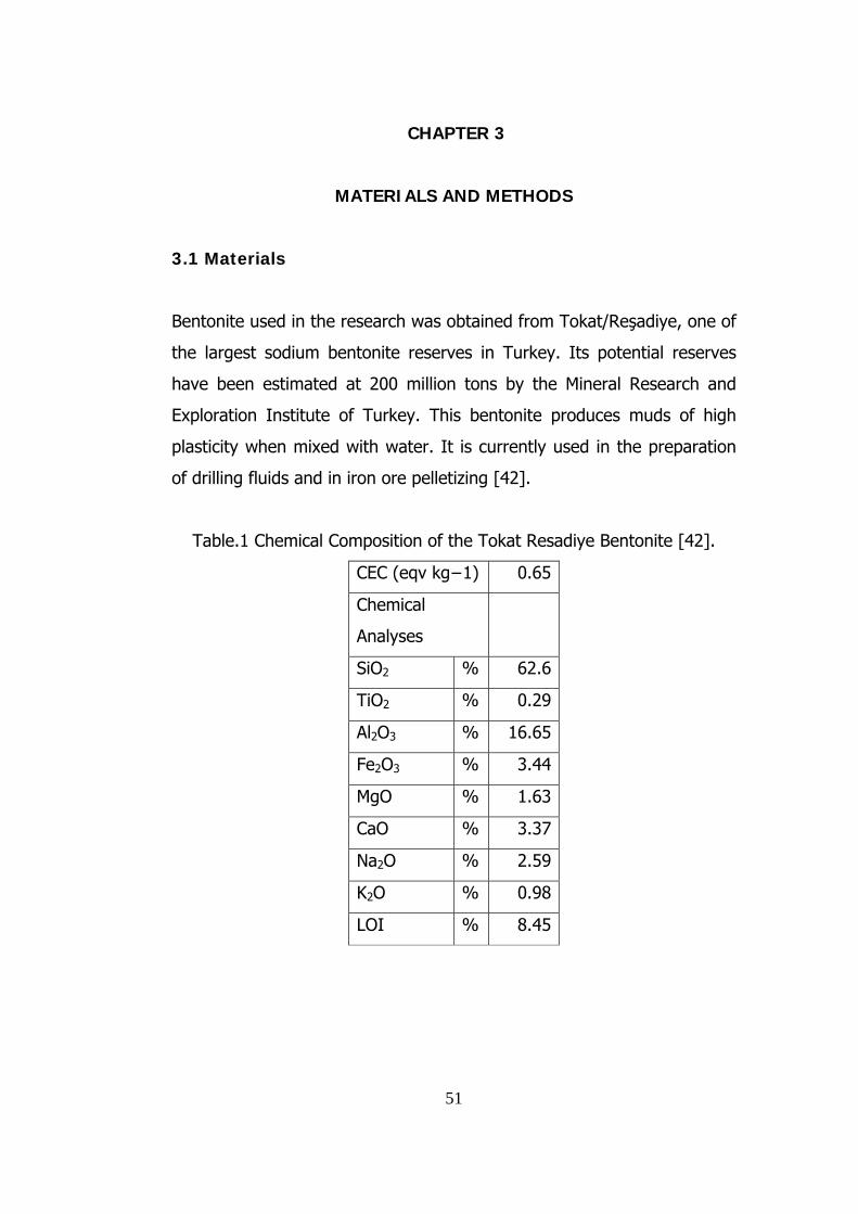
51
CHAPTER 3
MATERIALS AND METHODS
3.1 Materials
Bentonite used in the research was obtained from Tokat/Reşadiye, one of
the largest sodium bentonite reserves in Turkey. Its potential reserves
have been estimated at 200 million tons by the Mineral Research and
Exploration Institute of Turkey. This bentonite produces muds of high
plasticity when mixed with water. It is currently used in the preparation
of drilling fluids and in iron ore pelletizing [42].
Table.1 Chemical Composition of the Tokat Resadiye Bentonite [42].
CEC (eqv kg−1) 0.65
Chemical
Analyses
SiO2 % 62.6
TiO2 % 0.29
Al2O3 % 16.65
Fe2O3 % 3.44
MgO % 1.63
CaO % 3.37
Na2O % 2.59
K2O % 0.98
LOI % 8.45

52
In this research acetone, methyl-ethyl ketone and n-hexane were chosen
as organic fluidizing agents according to their interactions with clay
minerals, volatility, cost and toxicity. The organic liquids were obtained
from Aklar Kimya and the specifications are given in Appendix A.
Acetone is a manufactured chemical that is also found naturally in the
environment. It has a boiling point of 56 0C. It is a colorless liquid with a
distinct smell and taste. It evaporates easily, is flammable, and dissolves
in water. It is also called dimethyl ketone, 2-propanone, and beta-
ketopropane. Acetone is used to make plastic, fibers, drugs, and other
chemicals. It is also used to dissolve other substances. It occurs naturally
in plants, trees, volcanic gases, forest fires, and as a product of the
breakdown of body fat. It is present in vehicle exhaust, tobacco smoke,
and landfill sites. Industrial processes contribute more acetone to the
environment than natural processes [43].
Methyl ethyl ketone is a colourless liquid with a faint sweet odour. It has
a boiling point of 79 0C. Methyl ethyl ketone is a flammable liquid. It is
partially soluble in water, and soluble in most other organic solvents. It
will float on water while it rapidly dissolves in it. Methyl ethyl ketone is
used as a solvent for lacquers, adhesives; for cleaning materials to be
electroplated; for degreasing; in rubber and rubber cement, printing inks,
paints, wood stains, varnishes and paint removers and in cleaning
solutions; as a catalyst; and as a carrier. The primary sources of methyl
ethyl ketone emissions are the industries that either manufacture it or
use it in production, such as the chemical industry, rubber
manufacturers, the pharmaceutical industry, the semiconductor industry,
heavy equipment manufacturing, manufacturers of millwork, veneer and
plywood, and manufacturers of paints, inks, varnishes and lacquers.
53
These are emissions to the air unless there is a spill. Methyl ethyl ketone
occurs naturally in volcanoes, forest fires and bushfires, products of
biological degradation, and in some foods [44].
Hexane is an alkane hydrocarbon with the chemical formula
CH3(CH2)4CH3. It has a boiling point of 69 0C. It is a chemical made from
crude oil. Pure n-hexane is a colorless liquid with a slightly disagreeable
odor. It is highly flammable, and its vapors can be explosive. Pure n-
hexane is used in laboratories. Most of the n-hexane used in industry is
mixed with similar chemicals called solvents. The major use for solvents
containing n-hexane is to extract vegetable oils from crops such as
soybeans. These solvents are also used as cleaning agents in the
printing, textile, furniture, and shoemaking industries. Certain kinds of
special glues used in the roofing and shoe and leather industries also
contain n-hexane. Several consumer products contain n-hexane, such as
gasoline, quick-drying glues used in various hobbies, and rubber cement.
Hexane isomers are largely unreactive, and are frequently used as an
inert solvent in organic reactions because they are very non-polar. The
toxicity of hexane is relatively low, although it is a mild anesthetic.
Inhalation of high concentrations produces first a state of mild euphoria,
followed by somnolence with headaches and nausea [45].
3.2 Methods
3.2.1 Thermal Analysis
Thermogravimetric analysis (TGA) or thermogravimetry (TG) is a
technique in which the mass of the sample is monitored against time or
temperature while the temperature of the sample, in a specified
atmosphere, is programmed. Derivative thermogravimetry (DTG) is a

technique yielding the first derivative of the Thermogravimetric curve
with respect to either time or temperature [5]. Both TGA and DTG are
widely used in clay analysis.
Figure. 13 TGA equipment
Bentonite slurries were prepared by adding 10 grams of Resadiye
Bentonite to 20 ml of organic liquid. After 5 minutes of stirring the
slurries, the slurries and the blank sample was dried overnight at 105 oC.
Then the samples was stored in sealed bags for future use. All
experiments were performed by placing 20 mg sample and setting purge
air flow and heating the samples at a constant rate of 10 oC/minute to
the range of 900 oC.
3.2.2 Water Absorption Tests
A modified water absorption test was employed with reference to
standard test method for water absorption of bentonite by the porous
plate method designated by ASTM Committee E-1 given in Appendix B
[46].The water absorption apparatus consists of a plastic water
container, a sponge, Teflon ring and filter paper as shown in Figure 14.
54

1) The plastic box had dimensions of 31 cm in length, 22 cm in width
and 11.5 cm in height.
2) The size of the sponge with a density of 15kg/m3* used in the
tests was 28 cm long, 21 cm wide and 9.5 cm high. 8 cm of the
sponge was immersed in water
3) The Teflon ring had inside diameter of 2.50 cm outside diameter
of 4.90 cm and height of 2.30 cm. The Teflon ring was used to
control the spread of the bentonite sample which affects the water
absorption of the bentonite sample.
4) .The filter papers were Machery-Nagel fiber filter (MN 640 d).
Figure. 14 Water absorption apparatus
(*Determined by İşbir Sünger Test Laboratory)
55

The test procedure was as followed:
a) The water absorption of blank filter paper was determined by
weighing two filter papers allowed to wet on the sponge for given
length of time. This was carried out once before the absorption
tests.
b) Filter paper and the Teflon ring were weighed and placed on the
wetted sponge.
c) 1 g bentonite sample was weighed, placed in the ring and
uniformly spread.
d) The sample was allowed to absorb water for any given duration.
e) Teflon ring and filter paper was removed from the test container
and weighed.
f) Water absorption capacity was determined according to the
following equation:
100)(% xWd
WdWwAbsorption −= (3-1)
)( tefftw WWWW +−= (3-2)
Where
% Absorption = water absorption (% weight of water)
56

57
Ww = net weight of the hydrated bentonite
Wt = total weight of the hydrated bentonite, Teflon ring and the wetted
filter paper
Wf = weight of the wetted filter paper
Wd = net dry weight of dry bentonite
Wtef = Weight of the Teflon ring
3.2.3 Rheological Behaviour Analysis
The quantitative field measurements of mud system were accomplished
by utilizing a Fann VG meter, by measuring the shear stress at specific
shear rates according to specifications of American Petroleum Institute
(specification 13-c).The shear stress was read as the angular deflection
of a precision torsion spring. The various shear rates are provided by 6
standard motor speeds (3, 6, 100, 200, 300, 600 rpm).The rheological
behaviour analysis is described in the Appendix C.
3.2.4 Purification Tests
3.2.4.1 Purification of Bentonite by Using Non-Aqueous Media
The dispersion and purification of bulk bentonite was carried out by high
shear blending in a Laboratory Waren Blender (mod32bl80). The
dispersion of the bulk bentonite was determined by screening the
dispersed bentonite and the water adsorption tests were carried out to
determine the properties of undersize and oversize product.

58
Purification of bentonite samples by high shear blending procedure
follows:
a- 50g Bulk Reşadiye bentonite was put into the experiment flask
with 200 ml selected organic liquid.
b- Prepared slurry was subjected to high shear blending by Waring
laboratory blender (glass jar) for 2 minutes and 4 minutes with
cleaning the bounced bentonite from the jar inner surface with
organic liquid every 30 seconds.
c- The mixed slurry was sieved with 100# and the undersize and
oversize products were dried at 105 oC for 2 hours and the
weights were recorded.
d- This procedure was repeated for all organic liquids; acetone,
methyl-ethyl ketone and n-hexane.
e- The sieved samples and original bentonite sample were ground in
the ring pulverizer and dried at 105 oC.
f- Water absorption tests were carried out for the untreated,
undersize and oversize bentonite samples with duration of 24
hours.
Purification of bentonite by shaking was carried out by placing the
prepared bentonite sample in a plastic bottle and 200ml of organic liquid
was added to the flask containing 7 alumina balls with diameters of 1.50
cm. The flask was carefully set and allowed for 5 minutes shaking using a
wet screen machine as can be seen in Figure 15. The dispersed bentonite

samples were analyzed following the procedure for the procedure
purification of bentonite samples by high shear blending.
Figure. 15 Wet screen shaking mechanism for purification of bentonite
using non-aqueous media
3.2.4.2 Purification of Artificially Contaminated Bentonite by
Using Non-Aqueous Media
As the received bentonite was rather clean, not much remained in the
oversize material in the purification tests. Consequently, an artificially
contaminated clay sample was subjected to purification. Resadiye
bentonite used in this experiment was crushed into -1 mm then dried at
105 oC (overnight) to free the moisture. 40 grams (80%) of bentonite
sample was mixed with 10 grams (20%) of quartz (+ 500 µm – 2000
µm) as gangue mineral. Sample was subjected to purification as before
and was sieved with 100# and the undersize and oversize weights were
recorded. This procedure was repeated for all organic liquids; acetone,
methyl-ethyl ketone and n-hexane. The sieved samples and original
59

60
bentonite sample was ground in the ring pulverizer and dried at 105 oC.
Water absorption tests were carried out for the untreated, undersize and
oversize bentonite samples with duration of 24 hours.
3.2.5 Bentonite Absorption of Sponge Tests
The bentonite uptake from a non-aqueous suspension by a porous
medium was investigated by dipping a sponge cylinder into the non-
aqueous bentonite suspension.
a- The sponge cylinders of approximately 4 cm diameter and 3.75 cm
height were cut from a common purpose industrial sponge with
density of 17 kg/m3*and the weights were recorded.
b- The sponge cylinders were set into the beakers.
c- 25 grams of Reşadiye bentonite was added to 50 ml of organic
liquid and the slurry was mixed for homogenizing with magnetic
mixer for 5 minutes.
d- The homogenized slurry was poured to the beaker through the top
of the sponge cylinders. The beaker was slightly shaken for
diffusing the slurry inside the sponge.
e- The beaker was dried at 105 oC overnight. Then sponge was
cleaned up from superficially attached bentonite and the weight of
the adsorbed bentonite with the sponge mass was recorded. This
procedure was repeated until the sponges were saturated with
bentonite slurry with all 3 organic liquids.
(*İşbir Sünger Test Laboratory)
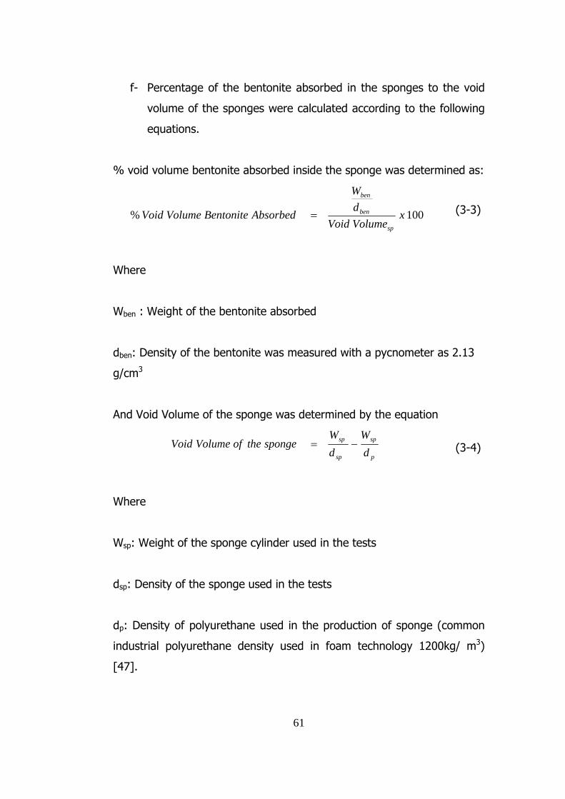
f- Percentage of the bentonite absorbed in the sponges to the void
volume of the sponges were calculated according to the following
equations.
% void volume bentonite absorbed inside the sponge was determined as:
100% xVolumeVoiddW
AbsorbedBentoniteVolumeVoidsp
ben
ben
= (3-3)
Where
Wben : Weight of the bentonite absorbed
dben: Density of the bentonite was measured with a pycnometer as 2.13
g/cm3
And Void Volume of the sponge was determined by the equation
p
sp
sp
sp
dW
dW
spongetheofVolumeVoid −= (3-4)
Where
Wsp: Weight of the sponge cylinder used in the tests
dsp: Density of the sponge used in the tests
dp: Density of polyurethane used in the production of sponge (common
industrial polyurethane density used in foam technology 1200kg/ m3)
[47].
61

62
CHAPTER 4
RESULTS AND DISCUSSIONS
4.1 Effect of Organic Liquids on the Thermal Characteristics of
Bentonite
The objective of this experiment was to investigate the thermal
properties of the bentonite samples treated with different organic
solvents and to determine the differences of the thermal properties of the
bentonite treated with organic solvents and untreated bentonite sample.
Thermal analysis of bentonite samples were carried by
Thermogravimetric analysis-Derivative thermogravimetry (TGA-DTG)
expressing the reactions occurred during heating such as dehydration,
dehydroxilation
The bentonite samples analyzed in this experiment exhibited two main
endothermic DTG peaks as shown in figures 17-20. The low temperature
peak that occurred in the temperature range 54-61 oC and the weight
loss event mainly corresponds to the evolution of remaining adsorbed
liquid and interlayer water. The high temperature peak occurring in the
range 690-694 oC corresponds to the dehydroxylation of clay minerals
[5].
According to TGA/DTG of the samples no significant difference in the
thermal behavior of acetone, methyl-ethyl ketone, and n-hexane treated
samples and untreated blank sample was observed. This indicates that
the organic compounds tested in this study do not change the structure
of bentonite. The results of analysis are given in Figure 16-19.

Figure. 16 TGA results for untreated bentonite
Figure. 17 TGA results for Acetone treated bentonite
63

Figure. 18 TGA results for methyl-ethyl ketone treated bentonite
Figure. 19 TGA results for n-hexane treated bentonite
64

65
4.2 Effect of Organic Liquids on the Water Absorption
Characteristics of Bentonite
The water adsorption tests were applied to organic liquid treated
bentonite clay to determine the effects of organic liquids on the water
absorption characteristics of clay and the differences between each liquid
and untreated bentonite.
10 g Resadiye Bentonite was treated with 20 ml of each of the organic
liquids and the slurry was fully dried at 105 oC (overnight). Then the
samples were stored in sealed bags for future use. The water absorption
properties of bentonite were investigated. The results are given in Table
2 and Figure 20.
Table 2 Water absorption of non-aqueous liquid treated bentonite
samples
% Weight of Water Time (hour)
Blank N-Hexane Acetone M.-E.-
Ketone
0 0 0 0 0
1 109.9 127.2 106.7 113.8
2 182.0 175.3 162.7 207.6
4 270.6 251.6 215.4 251.7
8 313.0 310.8 306.4 324.7
16 461.6 364.8 411.1 421.9
24 525.9 462.9 506.8 479.2
40 563.4 552.9 611.3 562.5
48 609.4 650.8 618.2 630.4
72 623.1 680.2 646.9 631.1

Figure 20 indicates no significant change in the water absorption
characteristics of bentonite treated with acetone, methyl-ethyl ketone
and n-hexane.
0
100
200
300
400
500
600
700
800
0 20 40 60 80Time (hours)
% W
ater
Abs
orpt
ion
BLANK
N-HEXANE
ACETONE
METHYL-ETHYLKETONE
Figure. 21 Water absorption of non-aqueous liquid treated bentonite
samples
4.3 Rheological Behavior of Bentonite in Aqueous and Non-
Aqueous Media
In this research, three non-aqueous organic liquids were tested as high-
solid bentonite slurry for low viscosity and effective usage for applications
and compared with aqueous slurry. All the measurements were carried
out by Fann VG meter with different amounts of bentonite in 350 ml fluid
(standard value).
66

67
For aqueous slurry the measurements were carried out with 10, 20, 30,
40 and 50 grams of bentonite in 350 ml. of water and shear stresses of
different bentonite concentrations at different shear rates are given in
table 3 and figure 21. The mud system showed fluidity for 10, 20, 30 and
40 grams of bentonite and the readings could not be obtained for 50
grams of bentonite.
Table.3 Shear Stresses (lbf/100 ft2) of different bentonite concentrations
for aqueous bentonite slurries at different shear rates
5.1
(3rpm)
10.2
(6rpm)
170
(100rpm)
340
(200rpm)
510
(300rpm)
1020
(600rpm)
10 g/ 350 ml 2 2 2 3 4 5
15 g/ 350 ml 2 2.5 3.3 4.5 5.8 8.5
30 g/ 350 ml 2.5 2.5 8 11 14 21.5
35 g/ 350 ml 2.5 4 12 15 25 40
40 g/ 350 ml 5 8 30 43 56 81
45 g/ 350 ml 16 19 70 100 121 170
50 g/ 350 ml 110 120
Shear Rate (sec -1)
Bentonite Concentration
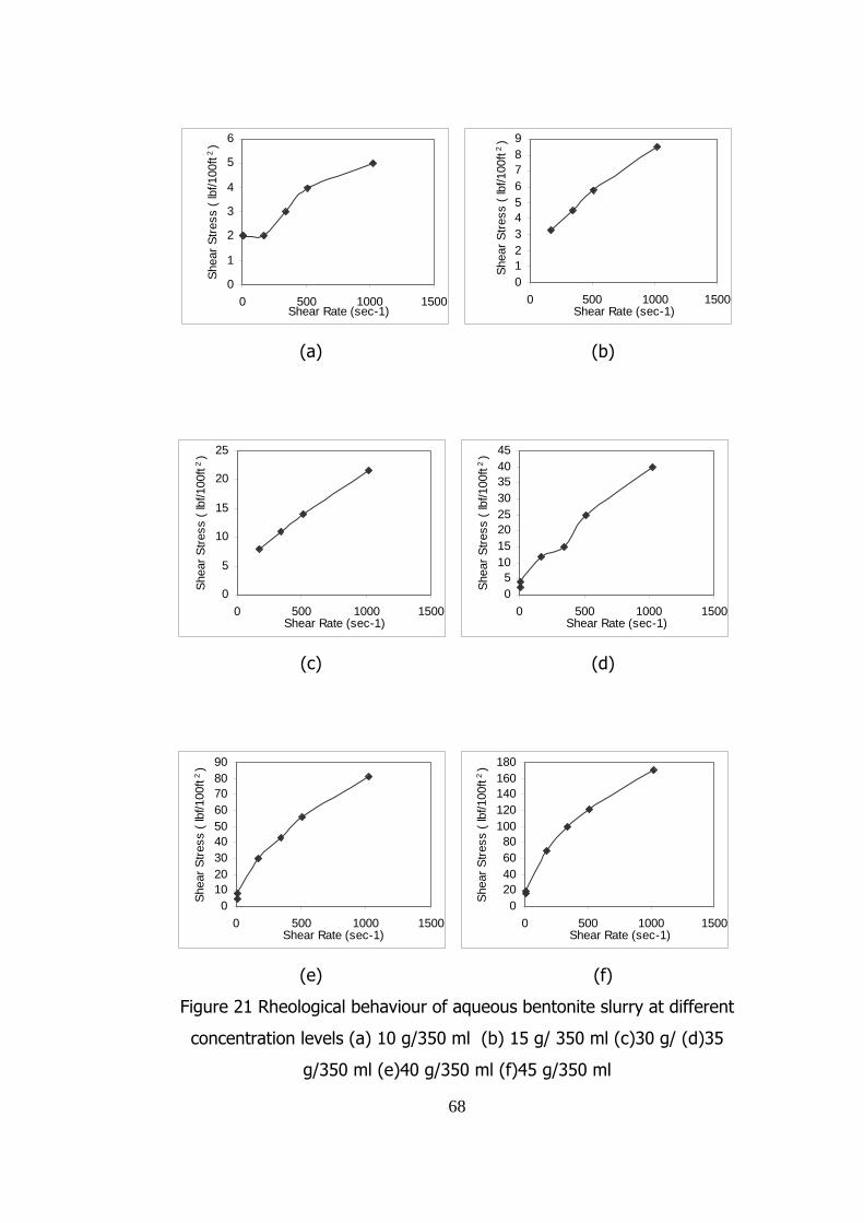
0
1
2
3
4
5
6
0 500 1000 1500Shear Rate (sec-1)
Shea
r Stre
ss (
lbf/1
00ft
2 )
0123456789
0 500 1000 1500Shear Rate (sec-1)
Shea
r Stre
ss (
lbf/1
00ft
2 )
(a) (b)
0
5
10
15
20
25
0 500 1000 1500Shear Rate (sec-1)
Shea
r Stre
ss (
lbf/1
00ft
2 )
05
1015202530354045
0 500 1000 1500Shear Rate (sec-1)
Shea
r Stre
ss (
lbf/1
00ft
2 )
(c) (d)
0102030405060708090
0 500 1000 1500Shear Rate (sec-1)
Shea
r Stre
ss (
lbf/1
00ft
2 )
020406080
100120140160180
0 500 1000 1500Shear Rate (sec-1)
Shea
r Stre
ss (
lbf/1
00ft
2 )
(e) (f)
Figure 21 Rheological behaviour of aqueous bentonite slurry at different
concentration levels (a) 10 g/350 ml (b) 15 g/ 350 ml (c)30 g/ (d)35
g/350 ml (e)40 g/350 ml (f)45 g/350 ml
68

69
For the non-aqueous media the measurements were done with mixing
the bentonite with acetone, methyl-ethyl ketone and n-hexane. Shear
stresses at different shear rates are given in Table 4 and Figure 22 for
acetone, Table 5 and Figure 23 for methyl-ethyl ketone and Table 6 and
Figure 24 for n-hexane mixed slurries for different bentonite
concentrations. The measurements were carried out with an initial
concentration of bentonite and an extra amount of bentonite was added
to the system for subsequent measurements. The flask containing slurry
was weighed before each measurement and the amount of evaporated
organic liquid was compensated. The interaction between bentonite,
acetone and methyl-ethyl ketone caused the slurry to be fluid until 200
grams for acetone and 225 grams for methyl-ethyl ketone. With n-
hexane, a different behaviour was observed. The bentonite particles
settled down quickly after the mixer was stopped. and the system
showed fluidity until 400 grams of bentonite.
Table .4 Shear Stresses (lbf/100 ft2) of different bentonite concentrations
for acetone bentonite slurries at different shear rates
5.1
(3rpm)
10.2
(6rpm)
170
(100rpm)
340
(200rpm)
510
(300rpm)
1020
(600rpm)
20 g/ 350 ml 1 1 1.5 2 2.5 3
30 g/ 350 ml 1 1 1.75 2 2.5 3
40 g/ 350 ml 1 1 2 2.5 3 3.5
50 g/ 350 ml 1 1.5 2.5 3 3.5 4.5
60 g/ 350 ml 2 2 2.5 3 3.5 4.75
70 g/ 350 ml 2 2.25 2.75 3.5 4.5 5.25
80 g/ 350 ml 2 2.5 3.5 4 5.25 6.5
150 g/ 350 ml 37 40 44 50
250 g/ 350 ml 137 145 151 171
Shear Rate (sec -1)
Bentonite Concentration

0
0,51
1,52
2,53
3,5
0 500 1000 1500Shear Rate (sec-1)
Shea
r Stre
ss (
lbf/1
00ft
2 )
0
0,51
1,52
2,53
3,5
0 500 1000 1500Shear Rate (sec-1)
Shea
r Stre
ss (
lbf/1
00ft
2 )
(a) (b)
00,5
11,5
22,5
33,5
4
0 500 1000 1500Shear Rate (sec-1)
Shea
r Stre
ss (
lbf/1
00ft
2 )
0
1
2
3
4
5
0 500 1000 1500Shear Rate (sec-1)
Shea
r Stre
ss (
lbf/1
00ft
2 )
(c) (d)
0
1
2
3
4
5
0 500 1000 1500Shear Rate (sec-1)
Shea
r Stre
ss (
lbf/1
00ft
2 )
0
1
2
3
4
5
6
0 500 1000 1500Shear Rate (sec-1)
Shea
r Stre
ss (
lbf/1
00ft
2 )
(e) (f)
Figure 22. Rheological behaviour of acetone bentonite slurry at different concentration
levels (a) 20 g/ 350 ml (b) 30 g/350 ml (c) 40 g/350 ml, (d) 50 g/350 ml (e) 60 g/350
ml (f) 70 g/350 ml (g) 80 g/350 ml, (h) 150 g/350 ml (i)250 g/350 ml
70
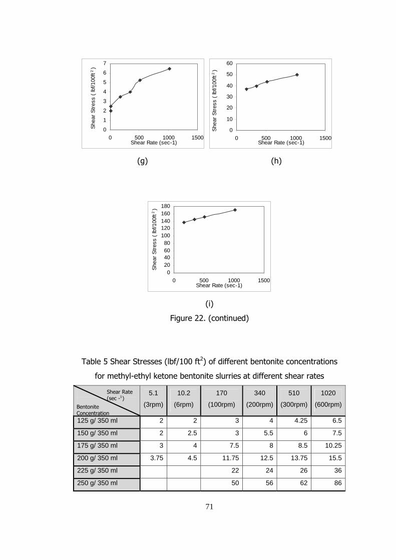
0
1
2
3
4
5
6
7
0 500 1000 1500Shear Rate (sec-1)
Shea
r Stre
ss (
lbf/1
00ft
2 )
0
10
20
30
40
50
60
0 500 1000 1500Shear Rate (sec-1)
Shea
r Stre
ss (
lbf/1
00ft
2 )
(g) (h)
020406080
100120140160180
0 500 1000 1500Shear Rate (sec-1)
Shea
r Stre
ss (
lbf/1
00ft
2 )
(i)
Figure 22. (continued)
Table 5 Shear Stresses (lbf/100 ft2) of different bentonite concentrations
for methyl-ethyl ketone bentonite slurries at different shear rates
5.1
(3rpm)
10.2
(6rpm)
170
(100rpm)
340
(200rpm)
510
(300rpm)
1020
(600rpm)
125 g/ 350 ml 2 2 3 4 4.25 6.5
150 g/ 350 ml 2 2.5 3 5.5 6 7.5
175 g/ 350 ml 3 4 7.5 8 8.5 10.25
200 g/ 350 ml 3.75 4.5 11.75 12.5 13.75 15.5
225 g/ 350 ml 22 24 26 36
250 g/ 350 ml 50 56 62 86
Shear Rate (sec -1)
Bentonite Concentration
71

0
1
2
3
4
5
6
7
0 500 1000 1500Shear Rate (sec-1)
Shea
r Stre
ss (l
bf/1
00 ft
2 )
012345678
0 500 1000 1500Shear Rate (sec-1)
Shea
r Stre
ss (l
bf/1
00 ft
2 )
(a) (b)
0
2
4
6
8
10
12
0 500 1000 1500Shear Rate (sec-1)
Shea
r Stre
ss (l
bf/1
00 ft
2 )
02468
1012141618
0 500 1000 1500Shear Rate (sec-1)
Shea
r Stre
ss (l
bf/1
00 ft
2 )
(c) (d)
05
10152025303540
0 500 1000 1500Shear Rate (sec-1)
Shea
r Stre
ss (l
bf/1
00 ft
2 )
0
20
40
60
80
100
0 500 1000 1500Shear Rate (sec-1)
Shea
r Stre
ss (l
bf/1
00 ft
2 )
(e) (f)
Figure 23. Rheological behaviour of Methyl-ethyl ketone bentonite slurry
at different concentration levels (a) 125 g/350 ml (b) 150 g/350 ml (c)
175 g/350 ml (d) 200 g/350 ml (e) 225 g/350 ml (f) 250 g/350 ml
72

Table. 6 Shear Stresses (lbf/100 ft2) of different bentonite concentrations
for n-hexane bentonite slurries at different shear rates
170
(100rpm)
340
(200rpm)
510
(300rpm)
1020
(600rpm)
125 g/ 350 ml 3.25 5.25 6.5 7.25
150 g/ 350 ml 3.5 4.5 6 7.75
175 g/ 350 ml 3.5 6 7 9
200 g/ 350 ml 5.5 6.5 8.25 11
225 g/ 350 ml 14 18
275 g/ 350 ml 11 13.5 16 20.75
325 g/ 350 ml 12 14.5 21 27.5
350 g/ 350 ml 15 17 26 36
425 g/ 350 ml 27 42 70 92
Shear Rate (sec -1)
Bentonite Concentration
012345678
0 500 1000 1500Shear Rate (sec-1)
Shea
r Stre
ss (l
bf/1
00 ft
2 )
0123456789
0 500 1000 1500Shear Rate (sec-1)
Shea
r Stre
ss (l
bf/1
00 ft
2 )
(a) (b)
Figure 24. Rheological behaviour n-hexane bentonite slurry at different
concentration levels (a) 125 g/350 (b) 150 g/350 ml(c) 175 g/350 ml (d)
200 g/350 ml (e) 225 g/350 ml (f) 275 g/350 ml (g) 325 g/350 (h) 350
g/350 ml.(i) 425 g/350 ml
73

0
2
4
6
8
10
0 500 1000 1500Shear Rate (sec-1)
Shea
r Stre
ss (l
bf/1
00 ft
2 )
0
2
4
6
8
10
12
0 500 1000 1500Shear Rate (sec-1)
Shea
r Stre
ss (l
bf/1
00 ft
2 )
(c) (d)
0
5
10
15
20
0 500 1000 1500Shear Rate (sec-1)
Shea
r Stre
ss (l
bf/1
00 ft
2 )
0
5
10
15
20
25
0 500 1000 1500Shear Rate (sec-1)
Shea
r Stre
ss (l
bf/1
00 ft
2 )
(e) (f)
0
5
10
15
20
25
30
0 500 1000 1500Shear Rate (sec-1)
Shea
r Stre
ss (l
bf/1
00 ft
2 )
05
10152025303540
0 500 1000 1500Shear Rate (sec-1)
Shea
r Stre
ss (l
bf/1
00 ft
2 )
(g) (h)
Figure 24 (continued)
74

0
20
40
60
80
100
0 500 1000 1500Shear Rate (sec-1)
Shea
r Stre
ss (l
bf/1
00 ft
2 )
(i)
Figure 24 (continued)
.
The yield points-plastic viscosities of different concentrations of aqueous
and non-aqueous bentonite slurries were calculated and given in Figure
25-28.
0
10
20
30
40
50
60
70
80
0 20 40 60Bentonite Concentration (g/350 ml)
Ty (l
bf/1
00 ft
2 )
0
10
20
30
40
50
60
70
80
Plas
tic V
isco
sity
(cp) Yield Point
PlasticViscosity
Figure 25 Yield Points-Plastic Viscosities of aqueous bentonite slurries at
different bentonite concentrations
75

0
20
40
60
80
100
120
140
0 50 100 150 200 250 300
Bentonite Concentration ( g/350 ml)
Ty (l
bf/1
00 ft
2 )
0
20
40
60
80
100
120
140
Plas
tic V
isco
sity
(cp)
YieldPoint
PlasticViscosity
Fig. 26 Yield Points-Plastic Viscosities of acetone bentonite slurries at
different bentonite concentrations
0
5
10
15
20
25
30
35
40
0 50 100 150 200 250 300
Bentonite Concentration (g/350 ml)
Ty (l
bf/1
00 ft
2 )
0
5
10
15
20
25
30
35
40
Plas
tic V
isco
sity
(cp)
YieldPoint
PlasticViscosity
Figure 27 Yield Points-Plastic Viscosities of methyl ethyl ketone bentonite
slurries at different bentonite concentrations
76
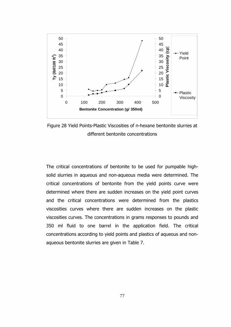
05
101520253035404550
0 100 200 300 400 500
Bentonite Concentration (g/ 350ml)
Ty (l
bf/1
00 ft
2 )
05101520253035404550
Plas
tic V
isco
sity
(cp)
YieldPoint
PlasticViscosity
Figure 28 Yield Points-Plastic Viscosities of n-hexane bentonite slurries at
different bentonite concentrations
The critical concentrations of bentonite to be used for pumpable high-
solid slurries in aqueous and non-aqueous media were determined. The
critical concentrations of bentonite from the yield points curve were
determined where there are sudden increases on the yield point curves
and the critical concentrations were determined from the plastics
viscosities curves where there are sudden increases on the plastic
viscosities curves. The concentrations in grams responses to pounds and
350 ml fluid to one barrel in the application field. The critical
concentrations according to yield points and plastics of aqueous and non-
aqueous bentonite slurries are given in Table 7.
77

78
Table. 7 Critical Yield Point-Plastic Point Concentrations for a pumpable
Bentonite Slurry
Fluid Type
Critical Yield Point
Concentration
(pounds/barrel)
Critical Plastic Point
Concentration
(pounds/barrel)
Water 35 30
Acetone 120 150
Methyl-Ethyl Ketone 175 200
N-Hexane 350 325
4.4 Purification of Bentonite
4.4.1 Purification of Bentonite Using Non-Aqueous Organic
Media
The purification tests were carried out by dispersion of the bentonite by
shearing and shaking, eliminating the non-clay impurities by screening
and characterizing the samples by water absorption. These researches
are carried for investigating alternative methods in beneficiation of
bentonite in the presence of organic liquids without grinding.
The results of the experiments conducted in order to test the method
proposed in section 3.2.4 are explained in this section and a conclusion is
obtained based on these results.
The test results for two minutes of blending raw bentonite in the
presence of an organic liquid with Waring Blender are 84% for acetone,
83% for methyl-ethyl ketone, and 64% for n-hexane treated bentonite
gained as a fraction of -100 meshes after screening. The dispersion and

79
water absorption of bentonite samples are given in Table 8 and Figure
29. The water absorption of bentonite samples did not differ significantly
due to the purity of the Resadiye Bentonite as can be seen in Figure 29.
Table 8. Dispersion and Water Absorption of Bentonite
Blending time: 2 minutes
The Organic Liquid Used Blending
time
(minute) Acetone Methyl-Ethyl Ketone N-hexane
2
minutes % weight
% Water
Absorption % weight
% Water
Absorption % weight
% Water
Absorption
-100# 83.986 557.8 83.059 521.3 63.916 497.4
+100# 16.014 506.1 16.941 517.2 36.084 516.4

2 minutes water absorption
0,0
100,0
200,0
300,0
400,0
500,0
600,0%
wat
er a
bsor
ptio
n
-100# 569,8 557,8 521,3 497,4
+100# 506,1 517,2 516,4
Blank Acetone M.-E.-Ketone N-Hexane
Figure 29 Water Absorption tests of -100# and +100 fractions of
bentonite dispersed in organic solvents followed by screening.
Blending time: 2 minutes
Next, tests were carried out for 4 minutes in order to improve the
dispersion of raw bentonite. The tests proved that nearly all 50 grams of
the bentonite could be gained as fraction of -100 meshes. Dispersion was
effectively accomplished mostly in the presence of acetone and methyl-
ethyl ketone. Water absorption tests did not indicate a significant change
with the untreated bentonite sample and organic liquid treated samples.
The results are given in Table 9 and Figure 30. The water absorption
80

81
tests for oversized material of acetone and methyl-ethyl ketone treated
samples could not be carried out since there were not sufficient amount
of samples.
Table 9 Dispersion and Water Absorption of Bentonite Blending time: 4
minutes
The Organic Liquid Used Blending
time
(minute) Acetone Methyl-Ethyl Ketone N-hexane
4
minutes % weight
% Water
Absorption % weight
% Water
Absorption % weight
% Water
Absorption
-100# 97.759 544.1 95.239 522.2 70.644 536.9
+100# 2.241 4.761 29.356 562.3

0,0
100,0
200,0
300,0
400,0
500,0
600,0
% w
ater
abs
orpt
ion
4 minutes water absorption
-100# 569,8 544,1 522,2 536,9
+100# 562,3
Blank Acetone M.-E.-Ketone N-Hexane
Figure 30. Water Absorption tests of -100# and +100 fractions of
bentonite dispersed in organic solvents followed by screening.
Blending time: 4 minutes
Next, dispersion of bentonite samples were carried out exposing the
bentonite samples to shaking forces for 5 minutes in the presence of
organic liquids by using wet screen machine. The dispersion was
effectively accomplished with the presence of acetone and methyl-ethyl
ketone treated samples. The results are given in Table 10. However; the
interaction of bulk bentonite with n-hexane was not sufficient for
dispersion and showed no significant change. The water absorption tests
82

83
indicate a clear improvement in the water absorption characteristics of
acetone treated samples. The water absorption of bentonite samples for
5 minutes shaking experiments are given in Figure 31. The most
satisfying results for purification of bentonite by blending and shaking
were obtained for acetone treated samples.
Table 10 Dispersion and Water Absorption of Bentonite Shaking time: 5
minutes
The Organic Liquid Used Shaking
time
(minute) Acetone Methyl-Ethyl Ketone
5
minutes
%
weight
% Water
Absorption
%
weight
% Water
Absorption
-100# 94.529 593.0 86.984 543.0
+100# 5.471 477.0 13.016 494.0

0,0
100,0
200,0
300,0
400,0
500,0
600,0
% w
ater
abs
orpt
ion
Blank Acetone M.-E.-Ketone
5 minutes water absorption
-100# 569,8 593,0 543,0
+100# 477,0 494,0
Blank Acetone M.-E.-Ketone
Figure 31. Water Absorption tests of -100# and +100 fractions of
bentonite dispersed in organic solvents followed by screening.
Shaking time: 5 minutes
4.4.2 Purification of Artificially Contaminated Bentonite by Using
Non-Aqueous Media
The bentonite samples used in purification tests were highly pure.
Therefore in order to investigate the purification of bentonite samples in
the organic liquids, the bentonite was artificially contaminated by 20%
quartz fraction by weight. The tests were realized by using a wet screen
machine exposing the sample to 5 minutes of shaking. Most of the 84
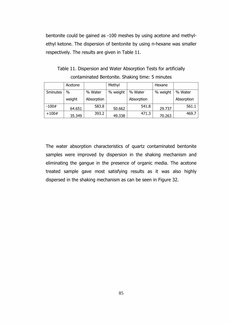
85
bentonite could be gained as -100 meshes by using acetone and methyl-
ethyl ketone. The dispersion of bentonite by using n-hexane was smaller
respectively. The results are given in Table 11.
Table 11. Dispersion and Water Absorption Tests for artificially
contaminated Bentonite. Shaking time: 5 minutes
Acetone Methyl Hexane
5minutes %
weight
% Water
Absorption
% weight % Water
Absorption
% weight % Water
Absorption
-100# 64.651 583.8 50.662 541.8 29.737 561.1
+100# 35.349 393.2 49.338 471.3 70.263 469.7
The water absorption characteristics of quartz contaminated bentonite
samples were improved by dispersion in the shaking mechanism and
eliminating the gangue in the presence of organic media. The acetone
treated sample gave most satisfying results as it was also highly
dispersed in the shaking mechanism as can be seen in Figure 32.

0,0
100,0
200,0
300,0
400,0
500,0
600,0
700,0
-100# 532,4 583,8 541,8 561,1
+100# 393,2 471,3 469,7
Blank Acetone M.-E.-Ketone N-Hexane
Figure 32. Water Absorption tests of -100# and +100 fractions of
artificially contaminated bentonite dispersed in organic solvents followed
by screening. Shaking time: 5 minutes
4.5 Bentonite Absorption Capacity for Sponge
Attempts were made for exploring a new kind of waterproofing bentonite
sheet consisting of industrial sponge saturated with organic liquid treated
swelling bentonite. During experiments the bentonite adsorption
capacities of the sponges with different organic liquid bentonite slurries
were determined.
86

87
The sponge cylinders used in the experiment were put in 100ml beakers
and 25 grams bentonite in 50 ml organic liquid mixed organic liquid-
bentonite slurries were slowly poured at the top of the sponge. The
beakers were shaken for complete absorption of bentonite through the
sponges. The sponges were dried and weighed, as explained in section
3.2.5. The test cycle was repeated until the sponges got saturated with
bentonite. The weights of the sponges and the bentonite absorbed after
each treatment is given in Table 12 and the weight of absorbed bentonite
according to number of treatment is given in Figure 33.
Table 12. Bentonite absorption of Sponge
Number
Of
Treatment
Acetone-
Bentonite
with
0.994g
sponge
m-e-
ketone-
bentonite
With
0.993g
sponge
n-hexane-
bentonite
with 0.982g
sponge
Amount
of
Bentonite
absorbed
(acetone)
Amount of
Bentonite
absorbed
(m-e
ketone)
Amount of
Bentonite
absorbed
(n-hexane)
1 20.946 21.376 16.113 19.952 20.383 15.131
2 31.569 45.616 30.403 30.575 44.623 29.421
3 42.023 46.669 40.187 41.029 45.676 39.205
4 45.052 46.334 46.315 44.058 45.341 45.333
5 45.339 * * 44.345 * *
* The sponge lost its ability to be used in experiment
According to procedure applied methyl-ethyl ketone-bentonite slurry was
rapidly absorbed by the experiment sponge as can be clearly seen in the
second recycled order of the experiment as shown in Figure 34. The test
procedure was reapplied until the experiment sponges lost their property
of absorbability and for all the non-aqueous slurry experiments ended up
with similar absorbing capacities.

Bentonite Absorption of Sponge
0
5
10
15
20
25
30
35
40
45
50
1 2 3 4 5
Number of Treatment
gram
s of
ben
toni
te a
bsor
bed
Acetone
Methyl EthylKetone
N-hexane
Figure 33. Bentonite absorption of sponge
The void volume of the sponges were determined as explained in section
3.2.5 by subtracting the polyurethane volume of the sponge from the
actual volume of the sponge and are given in Table 13.
Table 13 Volume of the Sponges
Volume of the Sponges
(cm3)
Void Volume of the Sponges
(cm3)
Acetone
M-E
Ketone
N-
Hexane Acetone
M-E
Ketone
N-
Hexane
58.47 58.412 57.764 57.642 57.584 56.946
88

89
The volume of the bentonite absorbed and the percentage of void
volume bentonite absorbed was determined and given in Table 14 and
Figure 34.
Table 14.% Void Volume Bentonite Absorbed
Volume of the bentonite
absorbed (cm3)
% Void Volume Bentonite
Absorbed
Number
of
Treatment
Acetone
M-E
Ketone
N-
Hexane Acetone
M-E
Ketone
N-
Hexane
1 9.367 9.569 7.104 16.251 16.618 12.4752 14.354 20.950 13.813 24.903 36.381 24.2563 19.262 21.444 18.406 33.417 37.240 32.3224 20.685 21.287 21.283 35.884 36.967 37.3745 20.819 36.118

% Void Volume Bentonite Absorbed
0
5
10
15
20
25
30
35
40
1 2 3 4 5
Number of Treatment
% V
oid
Volu
me
Ben
toni
te A
bsor
bed
Acetone
Methyl-EthylKetone
N-hexane
Figure 34. % Void Volume bentonite absorbed in the sponge Bentonite
absorption of sponge
90

91
CHAPTER 5
CONCLUSIONS
1. Bentonite treated with acetone, methyl-ethyl ketone and n-hexane
showed no structural changes as determined by TGA-DTG tests.
2. No significant changes were determined for the water absorption
characteristics of acetone, methyl-ethyl ketone, n-hexane treated
against untreated bentonite samples.
3. The rheological behaviour of bentonite slurries were investigated for
high-solid pumpable slurry. As aqueous slurry showed pumpable
properties up to 30-35 pounds/barrel, this concentration was as
high as 125-150 pounds/barrel for acetone, 175-200 pounds/barrel
for methyl-ethyl ketone and 325-350 pounds/barrel for n-hexane.
4. Dispersion of raw bentonite by exposing to high shear blending and
shaking then eliminating the non-clay impurities were investigated.
The bentonite was artificially contaminated with quartz (20 % by
weight) and exposed to shaking. The water absorption tests were
done for characterizing the samples. The presence of acetone gave
the most appropriate results for purification of bentonite.
5. The possible method for deposition of bentonite in a sponge by
saturating the sponge with bentonite using organic liquids was
investigated. The tests resulted with similar bentonite quantities
absorbed in sponges whereas the absorption of bentonite to the
sponge with methyl-ethyl ketone treated bentonite slurry was
significantly rapid.

92
REFERENCES
[1] Carroll, Paul W., February 21, 1995. Method for preparing high
solids bentonite slurries. United States Patent 5,391,228 ,
[2] Masanobu, Onikata and Mitsuji, Kondo, March 8, 1994. Modified
bentonite. United States Patent 5.292.908.
[3] Harriett, Todd D., March 7, 1989. Self-healing bentonite sheet
material composite article. United States Patent 4,810,573
[4] Alexander, William and Water, May, 12. 1992. Barrier of water-
swellable clay sandwiched between interconnected layers of
flexible fabric. United States Patent 5.112.665.
[5] Yariv, Shmuel and Cross, Harold, 2002. Organo-clay complexes
and interactions. New York, Marcel Dekker, p273-p345
[6] http://www.soils.umn.edu/academics/classes/soil2125/. Soil2125
Course Notes. Department of Soil, Water, and Climate University
of Minnesota
[7] Grim, Ralph E., 1988. The History of The development of Clay
Mineralogy, 704 West Florida Avenue, Urbana, Illinois 61801
Clays and Clay Minerals Vol. 36,No. 2,97-101.
[8] Van Olphen, H., 1977. An Introduction to Clay Colloid
Chemistry,National Academy of Sciences, Washington D.C., A
Wiley-Interscience Publication John Wiley& Sons New York
London Sydney Toronto
[9] Hofmann, U. and Endell, K. and Wilm, D. and Kristallogr, Z.,
1933.
[10] Luckham, Paul F. and Rossi, Sylvia, 1999. The colloidal and
rheological properties of bentonite suspensions Department of
Chemical Engineering and Chemical Technology, Imperial College,
Prince Consort Road, London SW7 2BY, UK ,Advances in Colloid
and Interface Science.

93
[11] Gouy, G., 1910. J. Phys.
[12] Gouy, G., 1917. Ann. Phys.
[13] Chapman, D. L., 1913. Philos. Mag.
[14] Stern, O. Z., 1924. Electrochem.
[15] Cremers, A. Israel, 1968. J. Chem
[16] Grahame, D. C., 1947. Chem. Rev.
[17] Derjaguin, B. V. and Landau, L. D., 1941. Acta Physicochim.
USSR
[18] Verwey, E. J. W. and Overbeek, J. Th.G., 1948, Theory of
Sttability of Lyophobic Colloids. Elsevier, Amsterdam. pp.216.
[19] Van Olphen, H., 1964. Colloid Interf. Sci.
[20] Norrish, K., 1954. Discuss. Faraday Soc.
[21] Callaghan, I. C. and Ottewill R. H., 1974. Faraday Discuss. Chem.
[22] Weiss, A. and Frank, R., 1961. Naturforsch.
[23] Fukushima, Y., 1984. Clays Clay Minerals.
[24] Theng, B. K., 1974. The Chemistry of Clay-Organic Reactions
Scientist. Soil Bureau, Department of Scientific and Industrial
Research, Lower Hutt, New Zealand, Halsted Press.
[25] Glaeser, R., 1948. On the mechanism of formation of
montmorillonite-acetone complexes. Clay Minerals Bull. pp.88-90
[26] Mackenzie, R. C., 1948. Complexes of clays with organic
compounds. II. Investigation of the ethylene glycol-water-
montmorillonite system using the Karl Fischer reagent. Trans.
Faraday Soc., pp.368-375.
[27] Dowdy, R. H., and Mortland, M. M., 1969. Alcohol-water
interactions on montmorillonite surfaces: II. Ethylene glycol. Soil
Sci. pp.36-43.

94
[28] MacEwan, D. M. C., 1948. Complexes of clays with organic
compounds. I. Complex formation between montmorillonite and
halloysite and certain organic liquids. Trans. Faraday Soc.,
pp.349-367
[29] German, W. L., and Harding, D. A., 1971. Primary aliphatic
alcohol-homoionic montmorillonite interactions. Clay Minerals
pp.167-175
[30] Bissada, K. K., Johns, W. D., and Cheng F. S., 1967. Cation-dipole
interactions in clay organic complexes. Clay Minerals. Pp.155-166
[31] Parfitt, R. L., and Mortland M. M., 1968.Ketone adsorption on
montmorillonite. Soil Sci. Soc. Am. Proc., pp.355-363.
[32] Barshad, I., 1952. Factors affecting the interlayer expansion of
vermiculite and montmorillonite with organic substances. Soil Sci.
Soc. Am. Proc. pp 176-182.
[33] Eltantawy, I. M., and Arnold, P. W., 1972. Adsorption of n-
alkenes by Wyoming montmorillonite. Nature Physc. Sci., pp.123-
125.
[34] De Boer, J. H., and Zwikker, C.,1929. Adsorption as a result of
polarization. The adsorption isotherm. Z. physik. Chem., pp 407-
418
[35] Fripiat, J. J.,1968. Surface fields and transformation of adsorbed
molecules in soil colloids. Trans 9th Int. Congr. Soil Sci., pp 679-
689
[36] Fairchild, Peter H. and Fairchild, Ian R., June 4, 2002. High solids
bentonite slurries and method for preparing same. United States
Patent 6,399,544.
[37] Payton, James and Canaris, Nicholas and Miranda, Jorge , April
18, 1995. Stabilized, High solids, low viscosity smectite slurries,
and method of preparation United States Patent 5,407,480

95
[38] Thompson, Thomas D., June 25, 1996. Process for treatment of
clay for use as a paper coating pigment, United States Patent
5.529.622,
[39] Goodman, Howard and Bleakley, Ian S., November 20, 1984.
Process for beneficiating bentonite. United States Patent
4.483.934.
[40] Powell, Clois E., May 4, 2004. Process for treating smectite clays
to facilitate exfoliation. United States Patent 6,730,719.
[41] Yamaji, Hajime and Kobayashi, Takeshi, December 17. 1985.
Aqueously-swelling Water Stopper and a Process for Stopping
Water Thereby. United States Patent 4.558.875.
[42] Önal, Müserref and Sarıkaya, Yüksel and Alemdoroğlu, Tülay and
Bozdoğan, İhsan, 19.03.2003. Isolation and Characterization of a
Smectite as a Micro-Mesoporous Material from a Bentonite.
Ankara University, Faculty of Science, Department of Chemistry,
Besevler, 06100 Ankara-TURKEY Eczacıbaşı, Ceramic Industries,
Kısıklı Cad.1, Altunizade, Üsküdar,81190 İstanbul-TURKEY.
[43] The Agency for Toxic Substances and Disease Registry (ATSDR),
http://www.atsdr.cdc.gov/tfacts21.html
[44]
The Australian Government Department of the Environment and
Heritage (DEH) develops http ://www.deh.gov.au/index.html
[45]
The Agency for Toxic Substances and Disease Registry (ATSDR),
http://www.atsdr.cdc.gov/tfacts113.html
[46] Standart Test Method for Water Absorption of Bentonite by the
Porous Plate Method ASTM Committee E-1 on Analytical
Chemistry for Metals, Ores, and Related Materials August 1992
[47] Klempner, Daniel and Frisch, Kurt C., 1991. Handbook of
Polymeric Foams and Foam Technology. Munich ; New York :
Hanser ; New York.

96
APPENDIX A
Table A1. Weights of Bentonite with wet filter for water absorption tests.
Weights of the Bentonites+Wet Filter Papers
Blank N-Hexane Acetone M.-E.-
Ketone
h(hours) (grams) (grams) (grams) (grams)
1 3.606 3.812 3.607 3.69
2 4.319 4.266 4.154 4.605
4 5.252 5.037 4.669 5.041
8 5.651 5.637 5.563 5.774
16 7.134 6.155 6.638 6.765
24 7.783 7.144 7.595 7.332
40 8.121 8.028 8.62 8.115
48 8.57 8.993 8.65 8.783
72 8.718 9.287 8.951 8.818

97
Table A2. Weights dry filter papers for water absorption tests.
Filter Paper (Grams) -Dry Weights
h(hour) Blank N-Hexane Acetone M.-E.-
Ketone
1 0.54 0.552 0.552 0.556
2 0.537 0.542 0.547 0.548
4 0.554 0.545 0.543 0.546
8 0.545 0.548 0.537 0.547
16 0.544 0.540 0.547 0.554
24 0.546 0.543 0.547 0.552
40 0.533 0.537 0.54 0.534
48 0.529 0.532 0.526 0.53
72 0.533 0.532 0.531 0.54
Table A3 Weights of Bentonite for 50 g/200 ml at 2 and 4 minutes
purification of bentonite experiments
Acetone
M.-E.-
Ketone Hexane
2
minutes (grams) (grams) (grams)
-100# 39.02 38.39 28.27
+100# 7.44 7.83 15.96
4
minutes
-100# 44.49 43.41 29.72
+100# 1.02 2.17 12.35

98
Table A4. Weights of Bentonite with wet filter papers for 2 and 4
purification of bentonite experiments
Weights of the Bentonites+Wet Filter Papers
Blank Acetone
M.-E.-
Ketone
N-
Hexane
2
minutes
(grams)
(grams) (grams) (grams)
-100# 8.180 8.026 7.709 7.509
+100# 8.180 7.551 7.679 7.682
4 minutes
-100# 8.180 7.889 7.715 7.89
+100# 8.180 8.071
Table A5.Weights dry filter papers for 2 and 4 minutes purification of
bentonite experiments
Filter Paper (Grams) –Dry Weights
Blank Acetone
M.-E.-
Ketone
N-
Hexane
2
minutes (grams) (grams) (grams) (grams)
-100# 0.531 0.519 0.536 0.55
+100# 0.531 0.534 0.54 0.544
4 minutes
-100# 0.531 0.519 0.535 0.545
+100# 0.531 0.519

99
Table A6 Weights of Bentonite for 50 g/200 ml at 5 minutes shaking
experiments
Acetone
M.-E.-
Ketone
5
minutes (grams) (grams)
-100# 41.99 37.69
+100# 2.43 5.64
Table A7. Weights of Bentonite with wet filter papers 5 minutes shaking
experiments
Weights of the Bentonites+Wet Filter
Papers
Blank Acetone
M.-E.-
Ketone
(grams) (grams) (grams)
-100# 8.180 8.426 7.979
+100# 8.180 7.238 7.483
Table A8 Weights dry filter papers for 5 minute shaking experiments
Filter Paper (Grams) -Dry Weights
Blank Acetone
M.-E.-
Ketone
-100# 0.531 0.536 0.555
+100# 0.531 0.526 0.553

100
Table A9. Weights of Bentonite with wet filter papers for 5 minutes
shaking experiments with gangue mineral
Weights of the Bentonites+Wet Filter Papers
Blank N-
Hexane
Acetone M.-E.-Ketone
(grams) (grams) (grams) (grams)
-100# 7.859 8.115 8.32 7.908
+100# 7.859 7.165 6.447 7.214
Table A10. Weights of dry filter papers for 5 minutes shaking
experiments with gangue mineral
Filter Paper (Grams) -Dry Weights
Blank N-
Hexane
Acetone M.-E.-Ketone
-100# 0.55 0.539 0.531 0.534
+100# 0.55 0.526 0.543 0.538

Filter Paper
y = 2,7907x
0
0,2
0,4
0,6
0,8
1
1,2
1,4
1,6
1,8
2
0 0,2 0,4 0,6 0,8
dry weight (grams)
wet
wei
ght (
gram
s)Linear (f ilterpaper)
Figure A1 Water Absorption of filter paper
101

102
Table A11 Specifications for Acetone
Assay 99.5%
Colour Pt-Co 5 max
Density 0.7915 g/cm3
Water 0.18%
M 58.08g/mol
Flash point -20 0C
Boiling Point 56 0C
Melting Point -95 0C
Odor Characteristic
KMnO4 time (min) >30
Acidity 0.0015%
Hydrocarbon Test negative
Appearance
clear and free
of susp
Solubility in Water soluble
Ph 5-6
Table A12 Specifications for Methyl Ethyl Ketone
Density 0.805 g/cm3
Flash Point -4 0C
Solubility in
water 292 g/l
M 72.11 g/mol
Ph 5.5
Melting Point -86 0C
Boiling Point 79 0C
Assay 99 0C

103
Table A13 Specifications for N-Hexane
Density 0.66 g/cm3
Solubility in Water 0.0095 g/l
M 86.18 g/mol
Melting Point -94.3 0C
Boiling Point 69 0C
Assay 98% min
Water 0.01% max

APPENDIX B
104

105

106

APPENDIX C
107

108

109

110