benefit b420 - | casall
TRANSCRIPT

1
Benefit B420
Bike
91101

2
ASSEMBLY INSTRUCTION

3
Stap 1
Assemble the base post (L) to the main frame with 5 screws(L3) and 5
washers(L2) and 5 spring washers(L1).
Stap 2
Fasten front and rear stabilizers each with 2 screws and washers to the base
construction. After the assembly the bike can be adjusted to slightly uneven
ground by adjusting the height of the foot caps in the back. The pre-assembled
transportation wheels in the front allow easy manoeuvring of the bike:
therefore the transportation-wheels need to point downwards to the front.
STEP1
STEP2

4
Stap 3
Screw pedals onto the crank. The pedals are marked with R and L at the
screw. Tighten the left pedal anticlockwise, the right pedal clockwise.
Step 4
1. Pull the tension cable out of the handlebar post and ensure the tension knob
is at lightest position (minimum position ).
2. Connect the tension cable by pushing the head into the notch of the cable
coming from the main frame. Connect the computer cables
3. First, loosen the pre-assembled screws. Then, put the handlebar post into
the main frame and fix it with 4 hexagon screws and washers.
4. Fasten the Bottle Cage to the Handlebar Mast using the screws .
STEP3
STEP4

5
Step 5
1. Assemble the saddle to the selector rail, position the rail onto the seat post
and tighten using the butterfly knob.
2. Insert the seat post in the main frame, choose the desired position and
tighten the knob. Ensure that the knob is always tightened.
Step 6
1. Place handlebar on the handlebar base, and position the metal cover on the
top of handlebar.
2. Next assemble all together with screw, spring washer, flat washer. Please
ensure it is tightened very well.
3. Place the plastic cover on the handlebar and insert T-shape knob into the
metal cover and assemble with spring washer, flat washer. Ensure again it is
tightened very well.
STEP5
STEP6

6
Step 7
1. Mount the computer to the hold of the handlebar pole with the enclosed
screws and connect the computer cables.
2. Plug the delivered hand-pulse wire for measuring the pulse rate in the
socket at the computer.
STEP7

7
PARTS LIST
PARTS NO. DESCRIPTION Q'TY
A,A1 Computer & Screw 1PCS
B Handlebar Post 1PCS
B1 Sensor wire upper 1PCS
B2 Screw M5xP0.8x14L 2PCS
B3 Tension control upper 1PCS
C Handlebar 1PCS
C1 Foam Grip 1SET
C2 Hand pulse 1SET
D Seat post 1PCS
D1 Seat Slider 1PCS
D2 Bolt hex 1PCS
D3 Seat Slider Knob 1PCS
D4 Flat Washer 2PCS
D5 Cover of seat slider 2PCS
E Bolt Allen 4PCS
E1 Washer 4PCS
F Front stabilizer 1PCS
F1 Transport wheel 1SET
G Main Frame 1PCS
H Magnet system 1SET
I Idler wheel set 1SET
J Flywheel set 1SET
K Knob for seat post 1PCS
K1 Chain cover (Left) 1PCS
K2 chain cover(Right) 1PCS

8
K3 Sensor Box 1PCS
K4 Tension control lower 1SET
K5 Screw M4x50L 5PCS
K6 Screw 3/16″(#10)x3/4″ 6PCS
K7 Belt J6 990m/m 1PCS
K8~K12,N1,N3 B.B. SET 1SET
L Main frame post 1PCS
L1 Flat Washer 5PCS
L2 Spring Washer 5PCS
L3 Bolt Allen 5PCS
M Rear stabilizer 1PCS
M1 End cap 1SET
N Pulley wheel 1PCS
N2 Crank 1PCS
O Seat 1pcs
O1 Bellow for seat post 1PCS
O2 Bottle cage 1PCS
O3 Pedal 1SET
P T knob 1PCS
P1 Clamp for handlebar 1PCS
P2 Clamp cover 1PCS
P3 Flat Washer 2PCS
P4 Spring Washer 2PCS
P5 Bolt for Handlebar 1PCS
P6 Bushing for T knob 1PCS
P7 Bolt Carriage 4PCS
P8 Washer 4PCS
P9 Hex Nut 4PCS

9
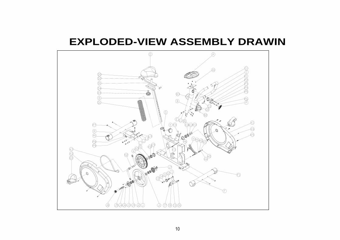
10
EXPLODED-VIEW ASSEMBLY DRAWIN

11
Monitor manual instruction ST7610-7
FUNCTION BUTTON MODE Press "Mode" button to preset TIME, DISTANCE, CALORIES and PULSE.
Press "Mode" button for selection, or enter after setting up.
SET To set up the value of TIME, DISTANCE, CALORIES and PULSE. You can hold the
button to increase the value faster. (The monitor has to be in stop condition.)
RESET The user may press "RESET" button to reset each function: Time, Distance, Calorie,
Pulse or hold on for 2 seconds for total reset.
(When the user replace batteries, all the values will reset to ZERO automatically.)
RECOVERY To act the heart rate recovery function after training.
FUNCTIONS SCAN Display all function from RPM - SPEED - DISTANCE - CALORIES - PULSE.
RPM Displays the Rotation Per Minute. The RPM and SPEED will switch to another display
in every 6 seconds after exercise starts.
TIME Accumulates workout time from 00:00 up to 99:59. The user may preset target time
pressing SET button. Each increasement is 1 minute.
SPEED Displays current training speed. Maximum speed is 99.9 KM/H or MILE/H.
DISTANCE Accumulates total distance from 0.00 up to 99.99 KM or MILE. The user may preset
target distance by pressing SET button. Each increasement is 0.1KM or MILE.
CALORIE Accumulates calories consumption during training from 0 to maximum 9999 calories.
(This data is a rough guide for comparison of different exercise sessions which can
not be used in medical treatment.)
PULSE After you hold two hands to the handgrip sensors, the monitor will display your current
heart rate figures. Before training starts, you may set up a target figure, when the heart
rate is exceed to this target, the monitor will show a blink heart rate symbol to remind
you.
TEMPERATURE Displays current room temperature from 0℃ to 60℃.
OPERATION ORDER 1. Installs 2 pieces of 1.5V #3 batteries, then the screen will display as following

12
“Drawing A” and have “Bi” sound at the same time.
Drawing A Drawing B 2. Get access to the set-up mode of TIME/DISTANCE/CALORIES/PULSE.
When you are in each set-up mode. For instance the time set-up, when the time value is blinking, you can press "SET" button to adjust the number. Press "Mode" button for confirmation and skip to next set-up. The set-up of DISTANCE & CALORIES is the same as TIME set-up.
3. After entering RPM value, and setting up the TIME, DISTANCE, CALORIES/PULSE. In SCAN mode shown as "Drawing C". RPM/SPEED/TM/DIST/CAL/PULSE will skip to display every 6 seconds. The order is as below "Drawing C"
Drawing C
4. You can also press "Mode" button to select single function display except RPM & SPEED function. The RPM & SPEED function will switch display. 5. When there is any function has been preset the target (TIME or DISTANCE or CALORIES), the function will be counting down from the preset to zero while the training starts. Once the target is achieved to zero, the monitor start to beep for 8 seconds, and the function will be counting up from zero directly if the training is going. 6. RECOVERY (1) When press "RECOVERY" button, the RECOVERY function will work. At this
time only PULSE and TIME is working, other function will not be displayed, and the Sensor Input is not available. TIME start to count down from "00:60". Pulse signal will be blinking according to user's pulse. When count down to "0", it will show F1~F6.
(2) LCD display as follows: (RECOVERY start condition & end condition)
Drawing D Drawing E
(3) If the count down action to 00:00 is not completed and there is no pulse signal. The count down action have to be done and shown F6. (4) If you press the RECOVERY button prior to count down to 00:00, it will be end the function and there will be no display at all.

13
NOTE 1. Stop training for 4 minutes, the main screen will be off and display the room temperature
automatically. 2. If the computer displays abnormally, please re-install batteries and try again. 3. Battery Spec: 1.5V UM-3 or AA (2PCS).

14