bicycle crash detector
TRANSCRIPT

Bicycle Crash Detector
Team 68-Qihao Wang, Jiayi Wu, Ruofan Hu
ECE445 Project Proposal-Spring 2020
TA: Chi Zhang

1 Introduction
1.1 Objective:
Bicycles are one of the most popular vehicles in the world because of its low price and
convenience. Moreover, recently, bicycle-sharing system has become popular in lots of cities.
With more people using bicycles as their primary vehicles, people also start to pay attention to
the safety issue around bicycles. Based on the data from the U.S department of transportation,
854 cyclists have died across the U.S and each year, around 55,000 cyclists are injured in the
U.S. Therefore, it is necessary to design a safety insurance system to provide extra help to
cyclists when they are seriously injured. Our goal is to design a bike crash system with
functionality of collision detection, automatic report crashes to policemen and alarm. The system
is designed to protect cyclists when they can not call for help because of deadly injury including
loss of consciousness and loss of hand functionality. The system will automatically send the
crash location along with default messages to the policemen and contact selected by the user.
Moreover, the alarm system will make sound and light signals so that the nearby people will
notice the crash.
1.2 Background:
The previous solution uses the combination of a spike in acceleration in one or more directions
with a rapid rotation in the bike's orientation to detect crash. It can detect crashes in most cases
but might generate false alarms when riders ride downhill on rugged mountain roads. In this
scenario, riders often turn the direction rapidly and brake sharly in order to keep balance and
slow down, but the original solution might recognize it as a crash. In our solution, we add an
alarm subsystem to which generate buzzer sound to inform people nearby. Besides, we can
cancel the alarm if we think we can deal with the crash by ourselves or this is a false alarm.
There are products in the market to detect the crash, but they do have alarm systems and require
users to wear helmets and have to cooperate with APP.

1.3 High-Level Requirement
● The system will be able to detect a crash and prevent false alarm from other controlled
cases with accuracy higher than 90%
● The system will be able to send a message to emergency contact(s) with a GPS location
along with the default message written by the user. The deviation of GPS location should
lower than or equal 5m radius.
● The solar power system can store enough charge for the system to work for 14 hours with
no sunlight.

2.Design 1. Block Diagram
Figure 2.1 Block Diagram

2.Physical Diagram:
Figure 2.2 Side View[7][8]
Figure 2.3 Top View

3. Block Descriptions
3.1 Power Module
A Power module will provide energy to the system so that the other module in the system can
function normally. A Li-ion battery will be charged by the solar panel. Then the power output
will be regulated to 3.7 V for the rest of the system.
3.1.1 Solar Panel
The solar panel will be the primary power source for the system. Its energy will be stored in a Li-
ion battery.
Requirement Verification
1.The panel can provide up to 1W, at 6 V and
180mA.
1. Step 1: we build a simple open‐circuit
measurer with a voltmeter.
And in series connect a current meter
to the power circuit
Step 2: Measure the open‐circuit
voltage with a voltmeter, ensuring that
the voltage 6V +/- 10%. And current is
180mA +/- 10% under normal sunlight

2.We require that the solar panel charge the
battery 1000mAh fully in under 7 hours of
sunlight.
2.
Step 1: We put power system under
sunlight for 7 hours
Step 2: We again use the simple circuit
open‐circuit voltage with a voltmeter
to measure the output of the Li-ion
battery to see if we have it fully
charged.

3.1.2 Charger Controller
The charge controller component will control the flow of the charge between the solar panel and
the Li-ion battery. It monitors the status of Li-ion and once the battery is full it stops charging.
Requirement Verification
1. The charger controller will allow current
pass through to the battery until it is full and
then stop charging.
1. Step 1: we build a simple open‐circuit
measurer with a voltmeter.
And in series connect a current meter
to the power circuit.
Step 2: Measure the open‐circuit
voltage with a voltmeter, ensuring that
the voltage 6V +/- 10%. And current is
180mA +/- 10% when the battery is
not fully charged
Step3: Once the battery is fully
charged. We should not see current
pass through from the the solar panel
to charge controller

3.1.3 Li-ion battery
The lithium-ion battery will store the necessary power for the system.
Requirement Verification
1. The battery must be able to store enough
charge to provide at least 150mA at 3.6 V for
10 hours with no sunlight.
1. Step 1: we build a simple open‐circuit
measurer with a voltmeter.
And in series connect a current meter
to the power circuit.
Step 2: Measure the open‐circuit
voltage with a voltmeter, ensuring that
the voltage 6V +/- 10%. And current is
180mA +/- 10% when the battery is
not fully charged
Step 3: Once the battery is fully
charged. We should not see current
pass through from the the solar panel
to charge controller

3.2 Sensor Module
We use the tilt Sensor and GPS for our sensor module. The tilt sensor is mainly used to detect
the crash and the GPS sensor is used to send our location to our communication module.
3.2.1 Tilt Sensor
We use tilt sensors for our sensor module. In our design, we put the tilt sensor on the side of the
bike and the top of the helmet to increase the accuracy. When the sensor inclines for more than
45 degrees, it will generate a ‘high’ signal [6] to the microcontroller and send the impact signal
to the control module through RF transmitter. The sensor module is small enough so that it will
not affect the rider.
Requirement Verification
1.Tilt Sensor should be able to send the ‘on state
signal’ (voltage low signal)
1. Step 1: We build a simple open‐circuit
measurer with a voltmeter.
Step 2: Measure the open‐circuit
voltage when the sensor is tilted more
than 45 degree. We should have a low
voltage signal.
2. The debounce code should help the Tilt
Sensor to distinguish the false described
previously and detect the actual crash with
accuracy higher than 90%
2. Step 1: We simulate all the false cases
including turning, brake suddenly and
small angle tilt. Each case for 10 times.
And we will record all voltage signals.
Step 2: We calculate our accuracy by
Accuracy = False Number/Total Test
Number

3.2.2 GPS
The GPS component can separate our system from the user phone, since the phone may be
unreliable in lots of cases including damage, power-off, or loss. We plan to use the SIM28ML
GPS module.
Requirement Verification
1.Must provide parsable GPS data within a
10m radius of the device.
1. Step 1: We connect the GPS to the
microcontroller so that we can record
all the GPS data.
Step 2: We will move around in two
popular environments including
normal campus environments such as
green street and park environment
which the users will encounter lots of
obstacles. Moreover, we also like to
test the GPS when we stay still
Step3: we will plot the GPS data on the
google map. And we can calculate the
the difference between our GPS data
and our actual location by formule
Diff = SUM(ABS(GPS DATA -
ACTUAL DATA))/Total data points
If we have avg below 10m radius, our
GPS is working properly

3.3 Control Module
The control module listens to the signal from the tilt sensors. When the controller module
receives the impact signal from helmet and bike simultaneously, it will detect the crash and send
an alarm signal to our alarm module.
Requirement Verification
1.The microcontroller should be able to
receive 1 bit signal from the tilt sensor and
the digital GPS signal by UMEA protocol
1. Step1: Connect the GSM module and
tilt sensor to the microcontroller and
send the information. We tilt the
sensor with angels 0, 60 ,90 degrees.
And we print out all the signal received
by the microcontroller
Step2: we check if we get the right
signal corresponding to the specific
case. For example, the 60-degree tilt
we should receive a voltage low
signal. We also verified GPS
information the same way as
described in GPS module
2.The microcontroller will generate control
signal and pass it to the alarm module
1. Step 1: we build a simple circuit using
the LED to distinguish 0 and 1 signals.
Step 2: We connect the circuit to the
output pin of the microcontroller. And
record the signal.
Step 3: Verify if the signal is the same
as our designed output.

3.The microcontroller will encode the GPS
information and default message and pass it
to the communication module
1. Step1: Connect the GSM module to the
microcontroller and send the
information. We would like to
performance this experiment in
different environment the same as
described in GPS verification
Step2: We calculate the success rate by
success cases/ total tests
We should get 90% to meet the
requirement.

3.4 Communication module
Again, the GSM module is also a necessary component for our system to work correctly without
a phone. The GSM module will connect to the antenna and send the default message along with
the location provided by the GPS module written by the user to the police department and the
user selected contact.
Requirement Verification
1.The GSM should send the default message
along with the location provided by the GPS
module written by the user to selected
contacts. The message should be sent
successfully 90% when the service of the
local phone network is available.
This function of this module will test together
with the Control Module. Please read the
Requirement 3 and verification of Control
Module.

3.5 Alarm Module
In the GPS module, we stated that GPS will only provide parsable data within a 10m radius of
the device. Therefore, we want to add these additional alarm devices so that the policemen or
nearby people can quickly locate the crash location.
3.5.1 Ring Alarm
Similar to a car, the major purpose of the ring alarm is to make loud noise so that the nearby
people will notice.
Requirement Verification
1.The sound should be around 95 dB and
should be clear within 10 m radius of the
device.
Step1: Turn on the ring alarm module.
And measure Decibel by Decibel
Meter.
3.5.2 Flashing Light
Similar to a car, the major purpose of the flashing light is to provide visual aid to nearby people
so that they can find the crash location fast and prevent a second crash.
Requirement Verification
1.The light should be clear within 10 m radius
of the device under normal condition and 5m
radius if the weather is terrible.
1. Step1: Turn on the flashlight module.
And we manually check if we can see
clearly from 10m away.
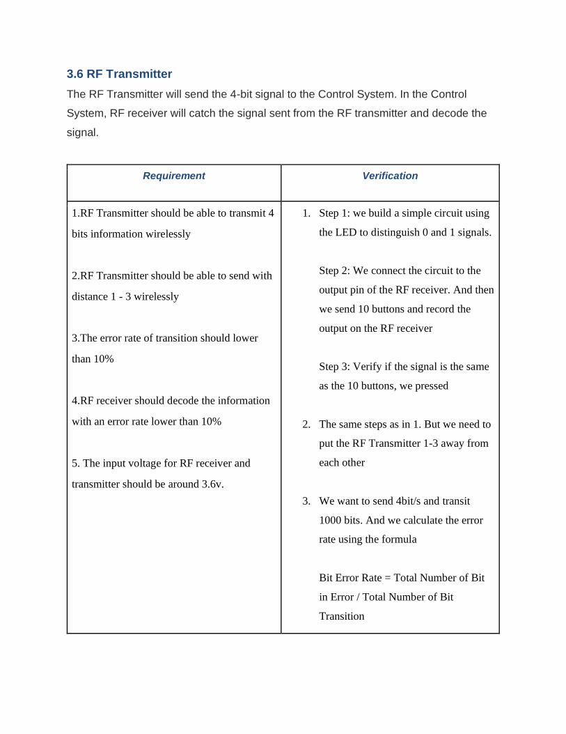
3.6 RF Transmitter
The RF Transmitter will send the 4-bit signal to the Control System. In the Control
System, RF receiver will catch the signal sent from the RF transmitter and decode the
signal.
Requirement Verification
1.RF Transmitter should be able to transmit 4
bits information wirelessly
2.RF Transmitter should be able to send with
distance 1 - 3 wirelessly
3.The error rate of transition should lower
than 10%
4.RF receiver should decode the information
with an error rate lower than 10%
5. The input voltage for RF receiver and
transmitter should be around 3.6v.
1. Step 1: we build a simple circuit using
the LED to distinguish 0 and 1 signals.
Step 2: We connect the circuit to the
output pin of the RF receiver. And then
we send 10 buttons and record the
output on the RF receiver
Step 3: Verify if the signal is the same
as the 10 buttons, we pressed
2. The same steps as in 1. But we need to
put the RF Transmitter 1-3 away from
each other
3. We want to send 4bit/s and transit
1000 bits. And we calculate the error
rate using the formula
Bit Error Rate = Total Number of Bit
in Error / Total Number of Bit
Transition

4. Measure the open‐circuit voltage
with a voltmeter, ensuring that it is
sound be around 3.3V.

4. Circuit:
The following circuit shows how the sensor part communicates with our control module.
Figure 4.1 circuit

5.Debounce Code(essential parts):
The debounce code filters out the false cases by examining the total time of tilting. The
comments in the code describe the function of every line.
Figure 5.1 Debounce Code

6.Tolerance Analysis
The stability of the power system is very important for our system to function properly. We want
to analyze our power consumption in sleep mode and activated mode. Sleep mode refers to the
case which the driver is driving normally. Under sleep mode, only tilt sensors, GPS modules, and
microcontrollers are consuming power. Activated mode refers to the case when a crash
happened. Under activated mode, all modules are consuming power.
Sleep Mode:
GPS Module Current Consumption = 8 uA
ATmega88 Current Consumption = 1.8 mA
SIM Module Current Consumption = 6.0 uA
RF sender/Receiver Current Consumption = 18.0 mA
Tilt Sensors = 12 mA
Total Current Consumption = GPS Module + ATmega88 + SIM Module + RF Module
= 8 uA + 1.8 mA + 6.0 uA +18.0 mA +12 mA
= 31.814 mA
Activate Mode:
GPS Module Current Consumption = 16 mA
ATmega88 Current Consumption = 1.8 mA
SIM Module Current Consumption = 350 mA
Buzzer = 10 mA
LED = 20 mA
RF sender/Receiver Current Consumption = 18.0 mA
Tilt Sensors = 12 mA
Total Current Consumption = GPS Module + ATmega88 + SIM Module + RF Module
= 16 mA + 1.8 mA + 350 mA +18.0 mA +12 mA +10 mA + 20 mA

= 417.8 mA
Now if we assume that the system will work 13 hours under Sleep Mode and 1 hour under
Activate Mode. We have
Combined Model Current Power Consumption = Activate Mode * 1 hour + Sleep Mode * 13 hours
Combined Model Current Power Consumption = 417.8 mA * 1 hours+ 31.814 mA * 13 hours
= 831.382 mAH
Next thing, we want to fully charge our Li-ion batteries with 7 hours of sunlight.
battery charger current = Battery Capacity / Charging time
Formula 6.1
battery charger current = 1000mAH / 7H = 142.857142857 mA
Therefore, in our project we choose a 180 mA solar panel and 1000mAH battery. In reality, the
power will be lost during the transition of different components, so we choose our solar panel
and battery larger than the result calculation. We believe that our power system should meet the
high-level requirement in our project.
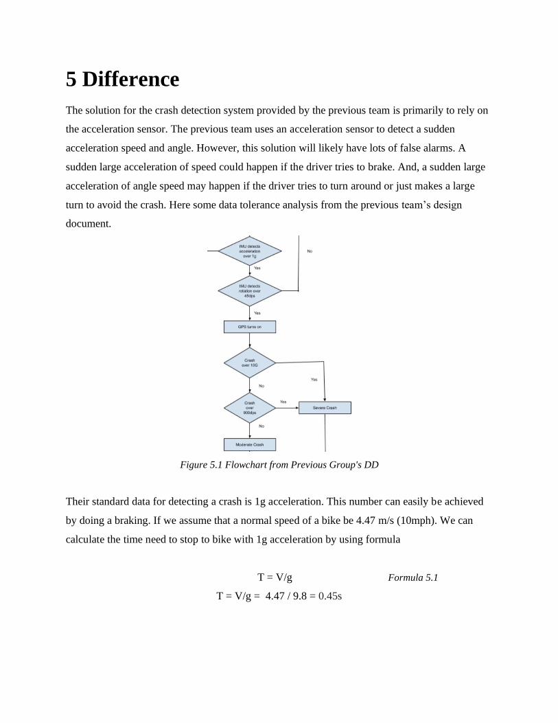
5 Difference
The solution for the crash detection system provided by the previous team is primarily to rely on
the acceleration sensor. The previous team uses an acceleration sensor to detect a sudden
acceleration speed and angle. However, this solution will likely have lots of false alarms. A
sudden large acceleration of speed could happen if the driver tries to brake. And, a sudden large
acceleration of angle speed may happen if the driver tries to turn around or just makes a large
turn to avoid the crash. Here some data tolerance analysis from the previous team’s design
document.
Figure 5.1 Flowchart from Previous Group's DD
Their standard data for detecting a crash is 1g acceleration. This number can easily be achieved
by doing a braking. If we assume that a normal speed of a bike be 4.47 m/s (10mph). We can
calculate the time need to stop to bike with 1g acceleration by using formula
T = V/g Formula 5.1
T = V/g = 4.47 / 9.8 = 0.45s

It is very hard to find a model about the change of acceleration for bike braking, but it is
reasonable to estimate a user will take 0.45s or less to stop a bike in normal cases. Therefore, the
previous team system will likely be activated during even the normal cases.
In our solution, we are using the tilt sensor to measure the tilt angle of the bike with respect to
the ground. Therefore, we will avoid all the false cases like brake and turn around. Moreover, we
will provide the debounce code and an emergency stop button to avoid false cases like a large
turn to avoid the crash. Here is a graph from the datasheet to show how the sensor works.
Figure 5.2 FlowChart from Previous Group's DD
Moreover, we will provide the debounce code to further avoid the false cases such as quick
turning. The debounce code will analyze the total tilt time. The debounce code will filter out the
case in which the bike only tilts more than 45 degrees for 1-5 seconds. These cases usually are
caused by turning and minor vibration. In addition, even our system is activated because of false
cases, we also provide an emergency stop button to allow the user to stop the system.
In the power aspect, the previous team uses a normal battery pack for all modules, which means
the user has to switch the battery consistently. Otherwise, the user may not have enough power
for the emergency cases. If we assume that users use bikes for 4 hours every day, the users will
need to switch the battery every 25 days. Here is a direct quote from the previous team’s design
document:
Figure 5.3 direct quote from the previous team’s design document

In our solution. we decide our system to use solar power so that the user does not need to worry
about the power. We believe solar power is a reasonable choice for the bike since people would
likely use the bike when the weather is good. The analysis about power in our system is
described in the tolerance analysis section. In summary, our system will work 14 hours without
sunlight and the battery can be charged in 7 hours under normal sunlight. Lastly, we also add a
simple alarm module to help nearby people to locate the crash location.
In our solution, we adapt the GPS and SIM module from their solution. GPS module provides
essential information for the police to locate the user. And with these two modules, the system
can work without any dependency on the user’s phone. Such independent functionality is crucial
since we do not know the status of the phone when the crash happened. Lastly, we also add a
simple alarm module to help nearby people to locate the crash location.
In conclusion, the solution provided by the previous team uses fewer components compared to
our solution. Therefore, their solution is less cost in money, energy and size. And the
acceleration sensor can provide the data with high accuracy such as angle speed and the moving
speed. However, their solution will likely result in a high false rate in detecting. In our solution,
we can detect the crash with high accuracy, and we use solar power to cover the power
consumption. On the other hand, our solution costs more money, energy and size since we have
more components.

6 Costs
Our fixed development costs are estimated to be $40/hour, 10 hours/week for three
people.
Our parts and manufacturing prototype costs are estimated as following:
Parts quantity cost description manufacturer
Small 6V 1W Solar
Panel - Silver
1 $19.9 Primary Power
source for the
system
Adafruit
RECHARGEABLE
3.7V 1000mAH LI-
ION BATTERY
1 $6.0 Primary Power
storage for the
system
Adafruit
USB / DC /
Solar Lithium Ion/Polymer charger - v2
1 $17.5 Charger
Controller
Adafruit
SIM28ML GPS
module
1 $6.6 GPS module SIMCom

ATmega168
microcontroller
1 $2.92 We will use the
microcontroller to
controller the
system
Microchip
Technology
GSM Module (SIM900A)
With Antenna
1
$9.64
The RF receiver
and RF sender,
which is the
necessary part
for our remote
controller
SIMCom
RED LED x 10 6 $9.5 Emergency
Flasher for the
alarm system
SparkFun
RS Pro by Allied
6173097
1 $2.9 Power Source Allied
Tilt Sensor - AT407
2 $3.9 Tilt Sensor LIGHT
COUNTRY
receiver/transmitter
NRF24L01
2 $4.2 The RF receiver
and RF sender,
which is the
necessary part for
our remote
controller
Nordic
Semiconductor
PCBs 2 No Cost Our design of
PCB should be 2
layers, the
website says it is
not cost
ECE SHOP
Total $78.86

Our calculation of cost is based on the minimum price in the market at this time and we
do not consider the shipping cost. Therefore, we would like to put a $20 possible extra
cost to the total cost.
In conclusion our total cost is

7 Schedule
Week Jiayi Wu Qihao Wang Ruofan Hu
WEEK 1 Research about the
background about Bike
Crash detect system
Research about the
possible design for a new
bike crash detect system
Research about the
possible design for a
new bike crash
detech system
WEEK 2 Finalize the high-level
requirement for Crash
Detech system project
Research about possible
choices for the crash detect
sensors
Design the solar
power system
WEEK 3 Doing the tolerance analysis
on the detect sensors system
Designing the prototype
circuit for the crash detect
sensors
Doing the tolerance
analysis on the solar
power system
WEEK 4
Writing the design part of
Document Design.
Writing circuit part of the
Document Design based
on the DDC
Writing tolerance
part of the
Document Design
based on the DDC
WEEK 5 Changing the design part of
Document Design based on
the DDC feedback.
Start to order all necessary
parts.
Changing circuit part of
the Document Design
based on the DDC
feedback
Start Design the PCB
Writing tolerance
part of the
Document Design
based on the DDC
Feedback
Start Design the
PCB

WEEK 6
Programming
microcontroller so that it
has the function to process
the input information for
other modules and output
the control signal to other
modules
Test the prototype circuit
of crash detect sensors
Test the prototype
circuit of solar
system
WEEK 7 Test the prototype circuit of
controller system, GPS and
alarm system on the
breadboard
Designing the PCB
Test the prototype
circuit of solar
power and tilt sensor
system
WEEK 8
Combine all parts and do
the Prototype machine
version 1 test
Finish and order version 1
PCBs (Early Bird)
Combine all parts
and do the Prototype
machine version 1
test
WEEK 9 Adjust the microcontroller
programming based on the
result of machine version 1
test
Adjust the PCB design
based on the Prototype
machine version 1 test
(Round 1)
Continue on the
Prototype machine
version 1 test with
change of circuit on
the breadboard.
WEEK 10
Combine all parts and do
the Prototype machine
version 2 test
Combine all parts and do
the Prototype machine
version 2 test
Combine all parts
and do the Prototype
machine version 2
test
WEEK 11 Running the verification of
launch subsystem
requirement
Adjust the PCB design
based on the Prototype
machine version 2 test
(Round 2)
Running the
verification of
remote controller
subsystem
requirement
WEEK 12 Reserve 1 week for any
delay of previous schedule
Reserve 1 week for any
delay of previous schedule
Reserve 1 week for
any delay of
previous schedule

WEEK 13 Prepare mock demo Prepare mock demo Prepare mock demo
WEEK 14 Begin final report Begin final report Begin final report
WEEK 15 Prepare final presentation Prepare final presentation Prepare final
presentation

Ethics and Safety
There are several safety and ethical issues involved in our system. The device itself is pretty
harmless to users but may have negative impacts on the public and cause ethic issues.
The first potential risk is the lithium battery that our system uses to store the energy. If disposed
improperly, lithium batteries can be very dangerous. Thus, we must prevent batteries from being
exposed to dangerous conditions like overcharging by monitoring the temperature of the battery
and warn our users of the potential hazards the batteries can do.
According to [5]IEEE code of ethics term No. 1, we must hold paramount the safety, health, and
welfare of the public, to strive to comply with ethical design and sustainable development
practices, and to disclose promptly factors that might endanger the public or the environment;
The functionality of our system involved alarming and automatic calling to the police office. So,
it is crucial for us to maintain the accuracy of our systems to avoid false alarms to the police or
the public which may jeopardize the public welfare and efficiency. Moreover, maintenance and
tracking are important to our system because our system is likely to be implanted on shared
bicycles which means there’s risk that it might get lost or stolen which will also affect the public
welfare.

Citations and References
[1] National Center for Statistics and Analysis, “Bicyclist and Pedestrian Safety -
nhtsa.gov,”NHTSA. [Online]. Available:
https://www.nhtsa.gov/sites/nhtsa.dot.gov/files/documents/14046-pedestrian_bicyclist_saf
ety_resources_030519_v2_tag.pdf. [Accessed: 18-Sep-2019].
[2] Fatality Facts 2018 [Online]. Available: https://www.iihs.org/topics/fatality-
statistics/detail/bicyclists.
[3] CYCLIST INJURIES FROM AUTO ACCIDENTS[Online]. Available:
https://bayareabicyclelaw.com/safety-laws/bike-stats/
[4] Renewable Energy World, ‘Solar-powered Internet Connectivity in Lascahobas, Haiti’, 2012.
[Online]. Available: http://www.renewableenergyworld.com/ugc/articles/2012/01/solarpowered-
internet-connectivity-in-lascahobas-haiti.html.
[5] “IEEE Code of Ethics.” IEEE. Accessed April 3, 2020.
https://www.ieee.org/about/corporate/governance/p7-8.html.
[6] SW-520d datasheet. Available:
http://funduino.de/DL/SW-520D.pdf
[7] image of bike. Available:
https://detroitbikes.com/products/b-type-1
[8] image of helmet. Available:
https://www.explorethousand.com/products/skateboard-
helmet?variant=31709206118447&utm_source=google&utm_medium=cpc&utm_campaign=TN
T%7CThousand%7CSmart%20Shopping%7CHelmets&utm_content=Helmets&gclid=CjwKCA
jwvZv0BRA8EiwAD9T2VcU2Oo0yrTFcqBN9-_i8QsH-
fgnbvijqKVfekRJ9hm0fBN0DHqA5zhoCp44QAvD_BwE
Sound intensity level
https://opentextbc.ca/physicstestbook2/chapter/sound-intensity-and-sound-level/

Li-lon Battery Charger with Thermal Regulation in SOP-8 Data Sheet:
https://dlnmh9ip6v2uc.cloudfront.net/datasheets/Prototyping/TP4056.pdf
RF receiver/sender Data Sheet:
https://www.sparkfun.com/datasheets/Components/nRF24L01_prelim_prod_spec_1_2.pdf
Previous Team’s Design Document:
https://courses.engr.illinois.edu/ece445/getfile.asp?id=16233