biomechanical evaluation of a novel limb prosthesis
TRANSCRIPT
Acta of Bioengineering and Biomechanics Original paperVol. 18, No. 4, 2016 DOI: 10.5277/ABB-00642-2016-02
Biomechanical evaluationof a novel Limb Prosthesis Osseointegrated Fixation System
designed to combine the advantagesof interference-fit and threaded solutions
PIOTR PROCHOR*, SZCZEPAN PISZCZATOWSKI, EUGENIUSZ SAJEWICZ
Department of Biocybernetics and Biomedical Engineering, Faculty of Mechanical Engineering,Białystok University of Technology, Białystok, Poland.
Purpose: The study was aimed at biomechanical evaluation of a novel Limb Prosthesis Osseointegrated Fixation System(LPOFS) designed to combine the advantages of interference-fit and threaded solutions. Methods: Three cases, the LPOFS (de-signed), the OPRA (threaded) and the ITAP (interference-fit) implants were studied. Von-Mises stresses in bone patterns andmaximal values generated while axial loading on an implant placed in bone and the force reaction values in contact elementswhile extracting an implant were analysed. Primary and fully osteointegrated connections were considered. Results: The resultsobtained for primary connection indicate more effective anchoring of the OPRA, however the LPOFS provides more appropriatestress distribution (lower stress-shielding, no overloading) in bone. In the case of fully osteointegrated connection the LPOFSskept the most favourable stress distribution in cortical bone which is the most important long-term feature of the implant usageand bone remodelling. Moreover, in fully bound connection its anchoring elements resist extracting attempts more than the ITAPand the OPRA. Conclusions: The results obtained allow us to conclude that in the case of features under study the LPOFS isa more functional solution to direct skeletal attachment of limb prosthesis than the referential implants during short and long-termuse.
Key words: finite element analysis, direct skeletal attachment, implants
1. Introduction
Nowadays, the most widely used method of at-taching external prosthesis to a lower limb stump isto use a prosthetic socket with appropriate mecha-nisms attached, for instance, frame locks, whichmakes it possible to attach the prosthesis connectorswith a socket [4], [6], [13], [20]. It is most com-monly performed on the basis of measurementstaken from the amputee’s cast which allows forcreating a negative and ultimately a positive to ac-curately reflect the state of the limb after amputa-tion [6]. Originally made socket requires a quick
exchange due to the stump’s tendency to change thevolume after the surgery. This process is caused bya bad circulation of body fluids and postoperativeedema, which stabilise during the healing period[4], [6], [13], [20].
Due to the continuous work, the geometry of thestump can be changed under the influence of variousloads acting on it. For this reason, it is advisableto supervise the prosthetic socket every three years andtake the appropriate adjustments or replacing it if re-quired. Improperly fitting connection may result in,among others, irritation and abrasion of the skin (incase of too tight connection) or sliding the funnel fromthe stump (if coupled less tightly) [4], [6], [13], [20].
______________________________
* Corresponding author: Piotr Prochor, Department of Materials and Biomedical Engineering, Białystok University of Technology,ul. Wiejska 45a, 15-351 Białystok, Poland. Tel: 502575276, e-mail: [email protected]
Received: January 12th, 2016Accepted for publication: March 20th, 2016
P. PROCHOR et al.22
The processes and related activities mentionedprove a necessity of developing new stump-externalprosthesis connection techniques. One such solutionmay be known, but rarely used implanting system,which examples can be the OPRA (OsseointegratedProstheses for the Rehabilitation of Amputees) andthe ITAP (Intraosseous Transcutaneous AmputationProsthesis) [15]. Implanting systems as the prosthesissuspensions are the development of the dental implantconcept [4], [13], [15], [24].
Implanting system is a single-element (the ITAP)or multi-element (the OPRA), also known as modu-lar, solution and is permanently implanted in boneduring surgery after reaming marrow cavity [4], [6],[13], [16], [20]. In order to anchor the implant moreeffectively, interference-fit connections are used(with irregular shapes and splines increasing interac-tion with surrounding bone), as in the case of theITAP solutions or a suitable thread used in theOPRA. Each of these connections has its advantagesand disadvantages. In the case of an interference-fitinvaluable advantage is the reduction of the stressesin the radial direction of bone (that cause its cutting),which are very high in the case of the threaded con-nection [13]. However, excessive bone stress thatarises at the bone–implant contact causes the localresorption [11], [21], [22], which after some timeresults in loosening of the implant connected to bonewith an interference-fit. This phenomenon also oc-curs in the case of a threaded connection [13] eventhough it is firmly anchored in bone by the threadteeth which provide a larger implant–bone contactarea.
Apart from the risk factors mentioned above, theuse of the implantation system may cause infectionsaround the implant [4], [8], [20]. However, it alsoprovides invaluable advantages [10], [18], [23],often impossible to obtain while using the pros-thetic socket. The advantages include: user’s com-fort, quick fastening, no skin abrasions, no need ofconstant putting in and removing the prosthesisconnecting element and others [4], [6], [16], [18],[20], [23]. A properly designed implanting systemcan provide new, yet unexplored advantages offixing prostheses, and therefore a growing interestin this method is visible.
The purpose of the present paper is to introducea new design of an implant for direct skeletal attach-ment of limb prosthesis that ensures a better stressdistribution in bone (than the implants of the refer-ence) while preserving anchoring elements. Theseproperties have been confirmed by finite elementanalyses presented in the following sections.
2. Materials and methods
2.1. The design of the new type of implantfor direct skeletal attachment
of limb prosthesis
Structure
The Limb Prosthesis Osteointegrated Fixation Sys-tem (LPOFS) consists of two parts: the glass-particle-reinforced PEEK (Polyether Ether Ketone) fixturescrewed in bone and the abutment placed in the fixture(Fig. 1). The fixture is hollow and consists of: a blockingcap, a cylindrically shaped segment A, and a triple-notched segment B of a conical shape with the spiralteeth on the outer part which increase in height withdistance from the cap (the outer diameter of the teeth 1is equal to the diameter of the outer segment A – it pre-vents rubbing the teeth against bone tissue during im-plantation of the fixture). Inside the segment A there isa metric thread for attaching the abutment and outsidea properly scaled thread for cortical bone type HA [19].Additionally, in order to provide better osteointegrationTi-coating is used on the fixture’s external surface.
The abutment (made of Ti6Al4V) consists of: thehead (description of the exact shape of the head is omit-ted, as it can be freely selected according to the needs ofthe connection with the exoprosthesis), the head’s shaft,the blocking cap, the cylindrical segment C notchedoutside with the metric thread and the conical segment Dthat ends with the closure cap whose diameter (2) isequal to the inner diameter of the cylindrical segment Aof the fixture. A porous layer (e.g., Ti-coating) is appliedto the head’s shaft in order to allow the soft tissue (skin)to ingrow the surface of the implant, which will reducethe risk of potential infection.
The efficiency of the materials considered was con-firmed by Tomaszewski’s implant project [21]. How-ever, it differs significantly from the design described interms of less beneficial way of implantation. The indi-vidual elements of the LPOFS are presented in Fig. 1.
The method of implantation process
The first step is reaming the marrow cavity for thelength of the fixture and a diameter slighly smallerthan the outer diameter of the fixture’s segment A (thediameter of the bottom of the thread’s notches). Thenext step is pushing the fixture into the drill hole untilthe start of the thread and finishing the implantationby screwing in the implant. It is followed by placingthe abutment inside the fixture and pushing it in to the

Biomechanical evaluation of a novel Limb Prosthesis Osseointegrated Fixation System... 23
beginning of the thread. The final step is to screw theabutment in until it shuts the closure cap of the abut-ment at the end of the fixture. A schematic way ofimplantation process is presented in Fig. 2.
Pressing the abutment in the fixture screwed in bonecauses expansion of B segments and thrusting its teethinto cortical bone. The aim is to preserve the benefits ofthe threaded and interference-fit connections.
2.2. Three dimensional CADand FE models
2.2.1. CAD models of implantsand cortical bone
The LPOFS solid model, the models of two im-plants of the reference: the OPRA (threaded) and theITAP (interference-fit), and model of cortical bonewere made in SolidWorks2015 software (Fig. 3).
Fig. 3. (a) CAD models of the LPOFS and the implantsof the reference (from left: the LPOFS, the ITAP, the OPRA);
(b) their positioning in cortical bone– made in SolidWorks2015
Fig. 1. The LPOFSs structure: W1 – the fixture (view): (A) cylindrical segment A; (B) conical, triple notched segment B;(a) blocking cap; (b) the implant thread for cortical bone; (c) helically cut teeth with an outer diameter equal to the outer diameter (1)
of segment A (bottom of the thread’s notches); (d) Ti-coating; W2 – the fixture (cross-section):(e) metric thread for attaching the abutment; L – abutment (view): (C) cylindrical segment C; (D) conical segment D; (f) head;
(g) head’s shaft with a porous layer; (h) abutment’s blocking cap; (i) metric thread for fixture attachment; (j) closure cap
Fig. 2. The method of implantation:(a) long bone after amputation; (b) reaming the marrow cavity;
(c) pressing and then screwing the fixture in bone;(d) pressing and then screwing the abutment
in until it shuts the closure cap– thrusting the teeth into cortical bone tissue

P. PROCHOR et al.24
In order to get comparable results, modelling in-cluded implants’ overall dimensions and identicalcortical bone dimensions. Each implantation systemincludes the same, simplified head’s shape of an im-plant, to which an external prosthesis is attached. Inthe case of the ITAP system the healing cap wasomitted, as it does not affect the load transfer andserves only for ingrowth of the skin. Overall dimen-sions of the models are summarised in Table 1.
2.2.2. FE models based on CAD designs
Previously created CAD models were exported toANSYS Workbench 16.2. Materials used for analysesand their properties are shown in Table 2.
To consider bone orthotropic properties a cylin-drical coordinate system was used. Discretisation ofmodels was performed using tetrahedral, 10-nodefinite elements Solid187 [1]. Face and edge sizing
was performed in the spots where cortical bone re-mained adjacent to the implant’s surface. This al-lowed more accurate results to be obtained in regionswhere the expected stresses in cortical bone weresupposed to be the greatest. Due to implants’ sym-metry it was possible to divide the models into twosymmetrical parts (using symmetry region operation)and analyse one of them. These changes resulted indecreasing the total number of elements in the meshwhich lead to hastening the calculation process.Contact elements (Conta174 and Targe170) werealso applied to include reciprocal interaction betweenthe bone and the implant [1]. The parameters of FEmodels are included in Table 3.
The differences in the quantity of nodes and ele-ments are the result of the implants’ constructions. Forthis reason, the ITAP of the simpliest construction hasthe lowest quantity, while the OPRA the highest due tothe thread noched on the whole length of its fixture.
Table. 1. The overall dimensions of the CAD models
Parameter LPOFS OPRA ITAP Parameter Cortical boneOuter diameter[mm] 30Length of cortical bone implanted section
[mm] 100 100 100Marrow cavitydiameter [mm] 18
Outer diameter of cortical bone implantedsection (Designed implant, ITAP) / Di-ameter of the top of the thread’s notches(OPRA) [mm]
20 20 20Length [mm] 200
Table 2. The mechanical properties of cortical bone and Ti6Al4V
Partname Material model Young’s modulus [GPa] Poisson’s
ratioShear modulus
[GPa]Density[kg/m3] Ref.
Isotropic(Glass-particle-
reinforced PEEK)12.5 0.400 4.46 1320 [21]
LPOFS
OPRAITAP
Isotropic(Ti6Al4V) 110.0 0.330 41.35 4500 [5], 17]
x (radial) 12.0 0.376 4.53y (transverse) 13.4 0.222 5.61Cortical
bone Orthotropic
Dire
c-tio
n
z (longitudinal) 20.0 0.235 6.231910 [2], [9]
Table 3. Number of nodes in finite element net and number of elementsin finite element mesh for different implant models
Model of implantplaced in bone
Quantityof nodes
Quantity of 10-nodetetrahedral elements
Quantityof contact elements
LPOFS 175066 100659 10349OPRA 194537 108447 17479ITAP 136578 78647 14879

Biomechanical evaluation of a novel Limb Prosthesis Osseointegrated Fixation System... 25
2.2.3. Boundary conditionsand loadings
To determine the implant–bone connection effec-tiveness the following cases were analysed:Case 1 – primary connection between bone and the
implant:Variant 1a – axial loading on the implant’shead;Variant 1b – extracting the implant from bone.
Case 2 – fully osteointegrated connection betweenbone and the implant:
Variant 2a – axial loading on the implant’shead;Variant 2b – extracting the implant from bone.
Case 1 – the primary connection between boneand the implant. It is characterised by the absence ofosteointergration resulting in friction between thesurfaces of the implant and bone. In this case mutualsliding between the contact elements of adjacing sur-faces was allowed. The friction coefficient betweenbone and the implant was set to 0.4 [22]. The calcula-tions were conducted using a Gauss point detectionmethod and augmented Lagrange formulation.
Analysing interference-fit connections (in thecases of the ITAP and the LPOFS) required deter-mining the primary influence of the implant on bonetissue (Fig. 4). To achieve this, the pressure during thepost-operative period of the implant–bone connectionwas set as an additional boundary condition on boneadjacent, external surfaces of the implants. The re-spective pressure values were estimated using formula(1) adapted from [3].
Fig. 4. Implant–bone interference-fit parameters
)1(22
22
ii
bb
b
b
r
vERv
RrRr
ER
p
(1)
wherep – implant–bone pressure in the interference-fit
connection [MPa];r – radial intererence between the implant and
reaimed marrow cavity [mm]; – interference-fit connection area of contact;R – nominal radius of connection [mm];Ei – Young’s modulus of the implant material
[MPa];Eb – Young’s modulus of bone in radial direction
[MPa];rb – external radius of bone [mm];νi – Poisson’s ratio of the implant material;νb – Poisson’s ratio of bone in radial direction.Due to the space between the B segment’s notches of
the LPOFS the interference-fit connection area of contact() is descreased by 22.17% comparing to ITAP-boneconnection, effectively lowering the pressure (Table 4).
Case 2 – fully osteointegrated connection betweenbone and the implant. To illustrate the assumed con-
ditions, the implant–bone connection was set as fullybound which also resulted in binding the contact ele-ments to prevent their mutual sliding. The bone ad-justment to the implant in the post-implantation pe-riod, resulting in significant lowering of pressure ininterference-fit connection was also taken into ac-count. Consequently, the pressure described in Table 4was omitted in the analysis.
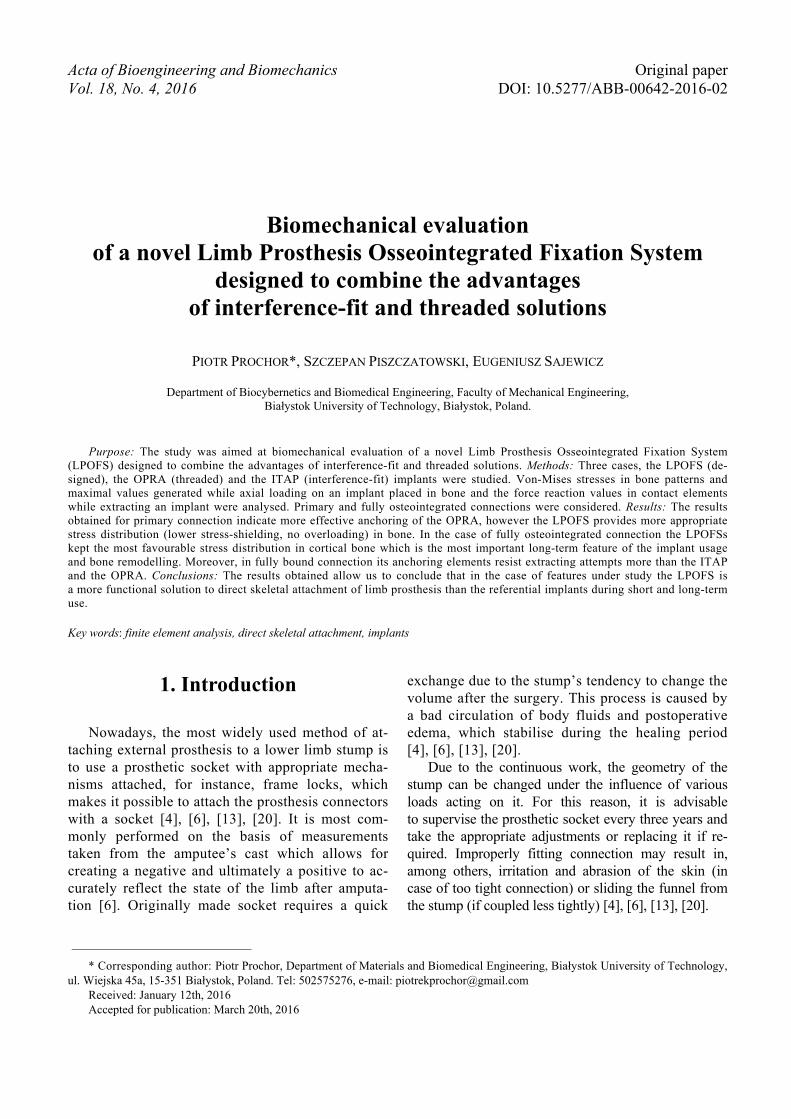
The fixed support was established at the distalsurface of cortical bone in case 1 as well as in case 2(Fig. 5).
Two variants of loadings were considered inboth cases. In “variants a” axial force was appliedon the head of each (Fig. 5a) to evaluate the im-plant’s displacement and stress pattern in bone.The hip joint carries the load 2 to 4 times greaterthan the weight of the body during gait [7], [12].Based on the data presented the force affecting thehead of the implant was estimated from 2000 N to4000 N. The assumptions correspond to a humanof a weight of 50 to 100 kg. In order to obtain ref-
Table. 4. Pressure of interference-fit connections and used calculation values
Model r[mm]
R[mm]
Ei[GPa]
Eb[GPa]
rb[mm] νi νb [%] P
[MPa]LPOFS 12.5 0.400 77.83 26.62ITAP
0.1 10110
12 150.330
0.376100 40.00
P. PROCHOR et al.26
erential data, a stress pattern in loaded non-im-planted bone was also considered.
In “variants b” the values of force reaction (lon-gitudinal direction) in contact elements on implant–bone interface were obtained while extracting theimplant from the bone. The purpose of the test wasto evaluate the efficiency of anchoring elementson the basis of the obtained force values. To simu-late the extraction process, a model was created inwhich the implant was extracted from bone, while ap-plying the displacement value from 0 mm to 0.1 mm(Fig. 5b).
3. Results
3.1. Determiningthe primary stability
The obtained results of maximal values of von-Mises stresses in bone, implants axial displacementsduring implant loading as well as force reaction (lon-gitudinal direction) in contact elements during implantextraction are presented in Table 5.
Fig. 5. Fixed support, force and displacement locations a) variants a; b) variants b
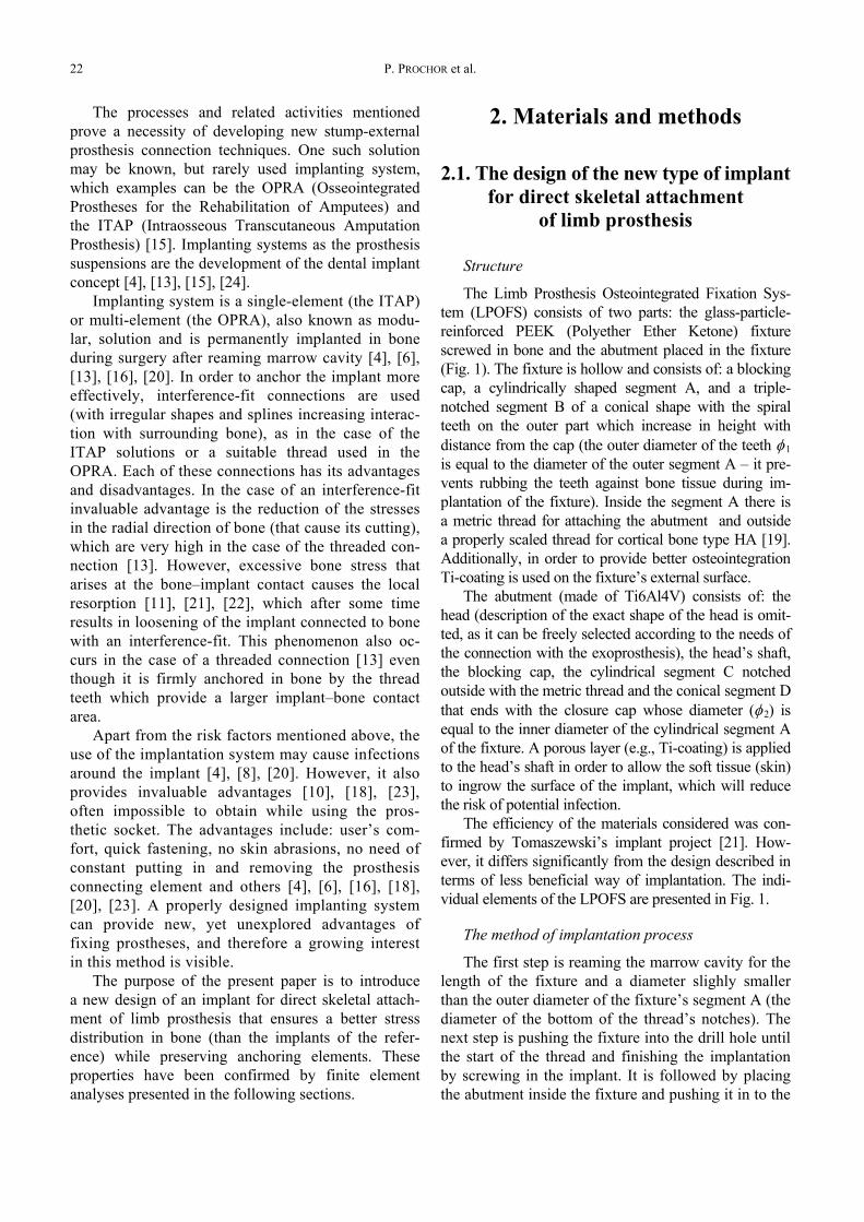
Table 5. Maximal values of von-Mises stresses in bone,implant axial displacement (bone loading)
and force reaction in contact elements (implant extraction) – primary stabilisation
Variant 1aMax. values
of von-Mises stress in bone[MPa]
Implant axial displacement[mm]
Force F [N] LPOFS ITAP OPRA Non-implanted LPOFS ITAP OPRA
2000 9.80 15.60 4.70 4.42 0.027 0.035 0.0262500 11.79 18.28 5.97 5.52 0.035 0.042 0.0323000 15.38 20.96 7.27 6.63 0.042 0.048 0.0393500 19.54 23.65 8.58 7.74 0.050 0.054 0.0454000 24.07 26.33 9.90 8.84 0.057 0.061 0.052
Variant 1b Max. values of force reaction (longitudinal direction)in contact elements on implant-bone interface [N]
Implant displacementΔd [mm] LPOFS ITAP OPRA
0.02 578.75 559.55 564.880.04 1049.50 646.50 1131.300.06 1518.70 769.84 1698.000.08 1986.00 775.78 2265.000.10 2451.70 778.81 2832.20
Biomechanical evaluation of a novel Limb Prosthesis Osseointegrated Fixation System... 27
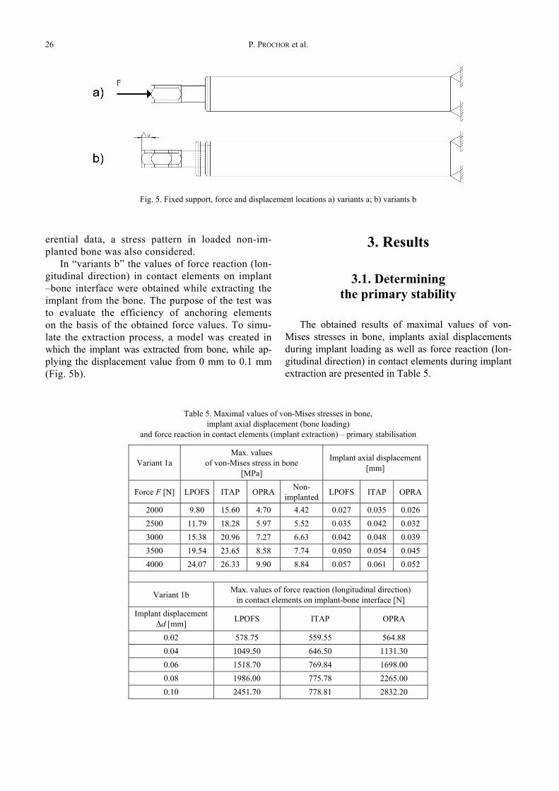
The stress patterns for the least favourable variant(F = 4000 N) and comparison of obtained force reac-tion values in contact elements during implant extrac-tion (Δd = 0.02 up to 0.1 mm) are shown in Fig. 6 andFig. 7.
Fig. 6. The stress patterns in bone [MPa] (primary stabilisation)upon axial loading of the implant’s head with a force of 4000 N:
(a) LPOFS; (b) ITAP; (c) OPRA
Fig. 7. The force reaction (longitudinal direction)in contact elements on implant–bone interface [N](primary stabilisation) while displacing the implant
by 0.02 up to 0.1 mm
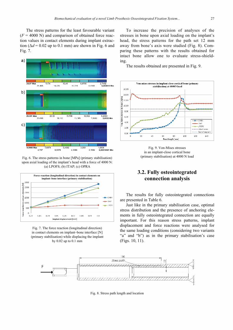
To increase the precision of analyses of thestresses in bone upon axial loading on the implant’shead, the stress patterns for the path set 12 mmaway from bone’s axis were studied (Fig. 8). Com-paring these patterns with the results obtained forintact bone allow one to evaluate stress-shield-ing.
The results obtained are presented in Fig. 9.
Fig. 9. Von-Mises stressesin an implant-close cortical bone
(primary stabilisation) at 4000 N load
3.2. Fully osteointegratedconnection analysis
The results for fully osteointegrated connectionsare presented in Table 6.
Just like in the primary stabilisation case, optimalstress distribution and the presence of anchoring ele-ments in fully osteointegrated connection are equallyimportant. For this reason stress patterns, implantdisplacement and force reactions were analysed forthe same loading conditions (considering two variants“a” and “b”) as in the primary stabilisation’s case(Figs. 10, 11).
Fig. 8. Stress path length and location
Force reaction (longitudinal direction) in contact elements onimplant–bone interface (primary stabilisation)
P. PROCHOR et al.28
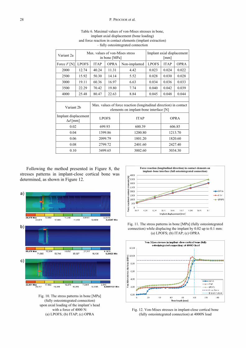
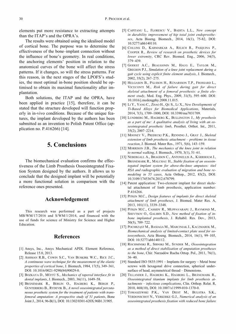
Following the method presented in Figure 8, thestresses patterns in implant-close cortical bone wasdetermined, as shown in Figure 12.
Fig. 10. The stress patterns in bone [MPa](fully osteointegrated connection)
upon axial loading of the implant’s headwith a force of 4000 N:
(a) LPOFS; (b) ITAP; (c) OPRA
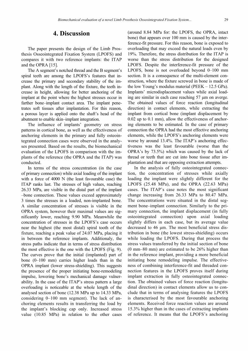
Fig. 11. The stress patterns in bone [MPa] (fully osteointegratedconnection) while displacing the implant by 0.02 up to 0.1 mm:
(a) LPOFS; (b) ITAP; (c) OPRA
Fig. 12. Von-Mises stresses in implant-close cortical bone(fully osteointegrated connection) at 4000N load
Table 6. Maximal values of von-Mises stresses in bone,implant axial displacement (bone loading)
and force reaction in contact elements (implant extraction)– fully osteointegrated connection
Variant 2a Max. values of von-Mises stressin bone [MPa]
Implant axial displacement[mm]
Force F [N] LPOFS ITAP OPRA Non-implanted LPOFS ITAP OPRA2000 12.74 40.24 11.31 4.42 0.023 0.024 0.0222500 15.92 50.30 14.14 5.52 0.028 0.030 0.0283000 19.11 60.36 16.97 6.63 0.034 0.036 0.0333500 22.29 70.42 19.80 7.74 0.040 0.042 0.0394000 25.48 80.47 22.63 8.84 0.045 0.048 0.044
Variant 2b Max. values of force reaction (longitudinal direction) in contactelements on implant-bone interface [N]
Implant displacementΔd [mm] LPOFS ITAP OPRA
0.02 699.93 600.39 606.850.04 1399.86 1200.80 1213.700.06 2099.79 1801.20 1820.600.08 2799.72 2401.60 2427.400.10 3499.65 3002.60 3034.30
Force reaction (longitudinal direction) in contact elements onimplant–bone interface (full osteointegrated connection)
Biomechanical evaluation of a novel Limb Prosthesis Osseointegrated Fixation System... 29
4. Discussion
The paper presents the design of the Limb Pros-thesis Osseointegrated Fixation System (LPOFS) andcompares it with two reference implants: the ITAPand the OPRA [15].
The A segment’s notched thread and the B segment’sspiral teeth are among the LPOFS’s features that in-crease the primary and secondary stability of the im-plant. Along with the length of the fixture, the teeth in-crease in height, allowing for better anchoring of theimplant at the point where the highest stresses occur infarther bone–implant contact area. The implant pene-trates soft tissues after implantation. For this reason,a porous layer is applied onto the shaft’s head of theabutment to enable skin–implant integration.
The influence of implants’ geometry on stresspatterns in cortical bone, as well as the effectiveness ofanchoring elements in the primary and fully osteoin-tegrated connection cases were observed in the analy-ses presented. Based on the results, the biomechanicalevaluation of the LPOFS in comparison with the im-plants of the reference (the OPRA and the ITAP) wasconducted.
In terms of the stress concentration (in the caseof primary connection) while axial loading of the implantwith a force of 4000 N (the least favourable case) theITAP ranks last. The stresses of high values, reaching26.33 MPa, are visible in the distal part of the implant–bone connection. These values exceed approximately3 times the stresses in a loaded, non-implanted bone.A similar concentration of stresses is visible in theOPRA system, however their maximal values are sig-nificantly lower, reaching 9.90 MPa. Meanwhile theconcentration of stresses in the LPOFS’s case occursnear the highest (the most distal) spiral tooth of thefixture, reaching a peak value of 24.07 MPa, placing itin between the reference implants. Additionaly, thestress paths indicate that in terms of stress distributionthe most effective is the one with the LPOFS (Fig. 9).The curves prove that the initial (implanted) part ofbone (0–100 mm) carries higher loads than in theOPRA implant (lower stress-shielding). This suggeststhe presence of the proper initiating bone-remodelingimpulse, lowering bone’s mechanical damage vulner-ability. In the case of the ITAP’s stress pattern a largeoverloading is noticeable at the whole length of theanalysed section of bone (12.38 MPa up to 14.33 MPa,considering 0–100 mm segment). The lack of an-choring elements results in transferring the load bythe implant’s blocking cap only. Increased stressvalue (10.85 MPa) in relation to the other cases
(around 8.84 MPa for: the LPOFS, the OPRA, intactbone) that appears over 100 mm is caused by the inter-ference-fit pressure. For this reason, bone is exposed tooverloading that may exceed the natural loads even by19%. Therefore, the stress distribution for the ITAP isworse than the stress distribution for the designedLPOFS. Despite the interference-fit pressure of theLPOFS, bone is not overloaded beyond 0–100 mmsection. It is a consequence of the multi-element con-struction, where the fixture screwed in bone is made ofthe low Young’s modulus material (PEEK – 12.5 GPa).Implants’ microdisplacement values while axial load-ing are similar in each case reaching 57 μm on averge.The obtained values of force reaction (longitudinaldirection) in contact elements, while extracting theimplant from cortical bone (implant displacement by0.02 up to 0.1 mm), allow the effectiveness of anchor-ing elements to be estimated. In the case of primaryconnection the OPRA had the most effective anchoringelements, while the LPOFS’s anchoring elements wereworse by around 13.4%. The ITAP’s anchoring effec-tiveness was the least favourable (worse than theOPRA’s by 73.5%) which was caused by the lack ofthread or teeth that are cut into bone tissue after im-plantation and that are opposing extraction attempts.
In the analysis of fully osteointegrated connec-tion, the concentration of stresses while axiallyloading the implant were slightly different for theLPOFS (25.48 MPa), and the OPRA (22.63 MPa)cases. The ITAP’s case notes the most significantchange increasing from 26.33 MPa to 80.47 MPa.The concentrations were situated in the distal seg-ment bone–implant connection. Similarly to the pri-mary connection, the implant displacement (in fullyosteointegrated connection) upon axial loadingslightly differs in each case, but its average valuedecreased to 46 μm. The most beneficial stress dis-tribution in bone (the lowest stress-shielding) occurswhile loading the LPOFS. During that process thestress values transferred by the initial section of bone(0 mm–80 mm) are estimated to be 26% higher thanin the reference implant, providing a more beneficialinitiating bone remodeling impulse. The effective-ness of combining interference-fit and threaded con-nection features in the LPOFS proves itself duringimplant extraction in fully osteointegrated connec-tion. The obtained values of force reaction (longitu-dinal direction) in contact elements allow us to con-clude that in terms of analysing features the LPOFSis characterised by the most favourable anchoringelements. Received force reaction values are around15.3% higher than in the cases of extracting implantsof reference. It means that the LPOFS’s anchoring
P. PROCHOR et al.30
elements put more resistance to extracting attemptsthan the ITAP’s and the OPRA’s.
The results were obtained using the idealised modelof cortical bone. The purpose was to determine theeffectiveness of the bone–implant connection withoutthe influence of bone’s geometry. In real conditions,the anchoring elements’ position in relation to theanatomical curves of the bone will affect the stresspatterns. If it changes, so will the stress patterns. Forthis reason, in the next stages of the LPOFS’s stud-ies, the most optimal in-bone position should be op-timised to obtain its maximal functionality after im-plantation.
Both solutions, the ITAP and the OPRA, havebeen applied in practice [15], therefore, it can bestated that the structure developed will function prop-erly in in-vivo conditions. Because of the unique fea-tures, the implant developed by the authors has beensubmitted as an invention to Polish Patent Office (ap-plication no. P.416266) [14].
5. Conclusions
The biomechanical evaluation confirms the effec-tiveness of the Limb Prosthesis Osseointegrated Fixa-tion System designed by the authors. It allows us toconclude that the designed implant will be potentiallya more functional solution in comparison with thereference ones presented.
Acknowledgement
This research was performed as a part of projectsMB/WM/17/2016 and S/WM/1/2014, and financed with theuse of funds for science of Ministry for Science and HigherEducation.
References
[1] Ansys, Inc., Ansys Mechanical APDL Element Reference,Release 15.0, 2013.
[2] ASHMAN R.B., COWIN S.C., VAN BUSKIRK W.C., RICE J.C.,A continuous wave technique for the measurement of the elasticproperties of cortical bone, J. Biomech, 1984, 17(5), 349–361,DOI: 10.1016/0021-9290(84)90029-0.
[3] BOZKAYA D., MÜFTÜ S., Mechanics of tapered interface fit indental implants, J. Biomech., 2003, 36(11), 1649–58.
[4] BRÅNEMARK R., BERLIN O., HAGBERG K., BERGH P.,GUNTERBERG B., RYDEVIK B., A novel osseointegrated percuta-neous prosthetic system for the treatment of patients with trans-femoral amputation: A prospective study of 51 patients, BoneJoint J., 2014, 96-B(1), DOI: 10.1302/0301-620X.96B1.31905.
[5] CAPITANU L., FLORESCU V., BADITA L.L., New conceptin durability improvement of hip total joint endoprosthe-ses, Acta Bioeng. Biomech., 2014, 16(1), 75-82, DOI:10.5277/abb140110.
[6] COLLINS D., KARMARKAR A., RELICH R., PASQUINA P.,COOPER R., Review of research on prosthetic devices forlower extremity, CRC Rev. Biomed. Eng., 2006, 34(5),379–439.
[7] GODEST A.C., BEAUGONIN M., HAUG E., TAYLOR M.,GREGSON P.J., Simulation of a knee joint replacement during agait cycle using explicit finite element analysis, J. Biomech.,2002, 35(2), 267–275.
[8] HELGASON B., PÁLSSON H., RÚNARSSON T.P., FROSSARD L.,VICECONTI M., Risk of failure during gait for directskeletal attachment of a femoral prosthesis: a finite ele-ment study, Med. Eng. Phys., 2009, 31(5), 595–600. DOI:10.1016/j.medengphy.2008.11.015.
[9] LI Y., YANG C., ZHAO H., QU S., LI X., New Developments ofTi-Based Alloys for Biomedical Applications, Materials,2014, 7(3), 1709–1800, DOI: 10.3390/ma7031709.
[10] LUNDBERG M., HAGBERG K., BULLINGTON J., My prosthesisas a part of me: A qualitative analysis of living with an os-seointegrated prosthetic limb, Prosthet. Orthot. Int., 2011,35(2), 2007–2214.
[11] MOONEY V., PREDECKI P.K., RENNING J., GRAY J., Skeletalextension of limb prosthesic attachment – problems in tissuereaction, J. Biomed. Mater Res., 1971, 5(6), 143–159.
[12] MORRISON J.B., The mechanics of the knee joint in relationto normal walking, J. Biomech., 1970, 3(1), 51–61.
[13] NEBERGALL A., BRAGDON C., ANTONELLIS A., KÄRRHOLM J.,BRÅNEMARK R., MALCHAU H., Stable fixation of an osseoin-tegated implant system for above-the-knee amputees: titelRSA and radiographic evaluation of migration and bone re-modeling in 55 cases, Acta Orthop., 2012, 83(2), DOI:10.3109/17453674.2012.678799.
[14] Patent application: Two-element implant for direct skele-tal attachment of limb prosthesis, application number:P.416266.
[15] PITKIN M.C., Design features of implants for direct skeletalattachment of limb prostheses, J. Biomed. Mater Res. A,2013, 101(11), 3339–3348.
[16] PITKIN M.C., CASSIDY R., MUPPAVARAPU J., RAYMOND M.,SHEVTSOV O., GALIBIN S.D., New method of fixation of in-bone implanted prosthesis, J. Rehabil. Res. Dev., 2013,50(5), 709–722.
[17] POCHRZĄST M., BASIAGA M., MARCINIAK J., KACZMAREK M.,Biomechanical analysis of limited-contact plate used for os-teosynthesis, Acta Bioeng. Biomech., 2014, 16(1), 99–105,DOI: 10.5277/abb140112.
[18] ROCHMINSKI R., SIBNSKI M., SYNDER M., Osseointegrationas a method of direct stabilization of amputation prosthesesto the bone, Chir. Narzadów Ruchu Ortop. Pol., 2011, 76(1),36–40.
[19] Standard ISO 5835:1991 – Implants for surgery – Metal bonescrews with hexagonal drive connection, spherical under-surface of head, asymmetrical thread – Dimensions.
[20] TILLANDER J., HAGBERG K., HAGBERG L., BRÅNEMARK R.,Osseointegrated titanium implants for limb prosthesis at-tachments – infectious complications, Clin. Orthop. Relat. R,2010, 468(10), DOI: 10.1007/s11999-010-1370-0.
[21] TOMASZEWSKI P.K., VAN DIEST M., BULSTRA S.K.,VERDONSCHOT N., VERKERKE G.J., Numerical analysis of anosseointegrated prosthesis fixation with reduced bone failure
Biomechanical evaluation of a novel Limb Prosthesis Osseointegrated Fixation System... 31
risk and peroprosthetic bone loss, J. Biomech., 2012, 45(11),1875–1880.
[22] TOMASZEWSKI P.K., VERDONSCHOT N., BULSTRA S.K.,VERKERKE G.J., A comparative finite-element analysis ofbone failure and load transfer of osseointegrated prosthesesfixations, Ann. Biomed. Eng., 2010, 38(7), 2418–2427.
[23] WEBSTER J.B., CHOU T., KENLY M., ENGLISH M.,ROBERTS T.L., BLOEBAUM R.D., Perceptions and accep-
tance of osseointegration among individuals with lower limbamputations: A prospective survey study, J. Prosthet. Orthot.,2009, 21(4), 215.
[24] ZHENG L., YANG J., HU X., LUO J., Three dimensionalfinite element analysis of a novel osteointegrated dentalimplant designed to reduce stress peak of cortical bone,Acta Bioeng. Biomech., 2014, 16(3), 21–28, DOI:10.5277/abb140303.