biomechanical simulation of lung deformation ... - … 2013 - biomechanical...
TRANSCRIPT
Biomechanical Simulation of Lung Deformationfrom One CT Scan
Feng Li and Fatih Porikli
Abstract We present a biomechanical model based simulation method for exam-ining the patient lung deformation induced by respiratory motion, given only oneCT scan input. We model the lung stress-strain behavior using a sophisticated hy-perelastic model, and solve the lung deformation problem through finite element(FE) analysis. We introduce robust algorithms to segment out the diaphragm controlpoints and spine regions to carefully define the boundary conditions and loads. Ex-perimental results through comparing with the manually labeled landmark points inreal patient 4DCT data demonstrate that our lung deformation simulator is accurate.
1 Introduction
The use of four-dimensional computed tomography (4DCT) has becoming a com-mon practice in radiation therapy, especially for treating tumors in thoracic areas.There are two alternative methods for 4DCT acquisition, namely retrospective slicesorting and prospective sinogram selection. No matter which method is used, theprolonged acquisition time results in a considerably increased radiation dose. Forexample, the radiation dose of a standard 4DCT scan is about 6 times of that of atypical helical CT scan and 500 times of a chest X-ray. Moreover, 4DCT acquisitioncannot be applied to determine the tumor position in-situ. These facts have becomea major concern in the clinical application of 4DCT, motivating development ofadvanced 4DCT simulators.
Towards this goal, various approaches have been proposed to model lung infla-tion/deflation. The first category of methods discretize the soft tissues (and bones)into masses (nodes) and connect them using springs and dampers (edges) based on
Feng LiMitsubishi Electric Research Laboratories, Cambridge, MA 02139, USA.
Fatih PorikliMitsubishi Electric Research Laboratories, Cambridge, MA 02139, USA.
1
2 Feng Li and Fatih Porikli
mass-spring-damper system and CT scan values for spline-based MCAT phantoms[16], augmented reality based medical visualization [15], respiration animation [23],tumor motion modeling [21], and etc. Conventionally, they apply affine transforma-tions to the control points to simulate respiratory motion. Lungs and body outlineare linked to the surrounding ribs, such that they would have the synchronized ex-pansion and contraction [16]. These approaches can only provide approximate de-formations.
The second category of methods use hyperelastic models to describe the non-linear stress-strain behavior of the lung. The straightforward way to simulate lungdeformation between two breathing phases (Ti,Ti+1) is to use the lung shape at Ti+1as the contact/constraint surface and deform the lung at Ti based on the predefinedmechanical properties of lung [18, 10]. In this case, a negative pressure load on thelung surface is applied and Finite Element (FE) analysis is used to deform tissues[22]. The lung will expand according to the negative pressure and slide against thecontact surface to imitate the pleural fluid mechanism [3]. This pressure can beestimated from the patient’s pleural pressure vs. lung volume curve, which in turnare measured from pulmonary compliance test [20]. Along this line, patient-specificbiomechanical parameters on the modeling process for FE analysis using 4DCTdata are learned in [19]. A deformable image registration of lungs study to find theoptimum sliding characteristics and material compressibility using 4DCT data ispresented in [1].
Besides lung deformation, the displacements of rib cage and diaphragm are alsovery important to design a realistic 4DCT simulator. Didier et al. [6] assume the ribcage motion is a rigid transformation and use finite helical axis method to simulatethe kinematic behavior of the rib cage. They develop this method into a chest wallmodel [7] relating the ribs motion to thorax-outer surface motion for lung simula-tion. Saade et al. [14] build a simple diaphragm model consisting of central tendonand peripheral muscular fibre. They apply cranio-caudal (CC) forces on each nodeof the muscular fibre to mimic the diaphragm contraction and use Gauchy-Greendeformation tensor to describe the lung deformation. Hostettler et al.[11] considerinternal organs inside the rib cage as a convex balloon and estimate internal defor-mation field directly through interpolation of the skin marker motions.
Patient-customized deformation approaches often assume a 4DCT of the patientis already available. We note that simulating deformations without any 4DCT hasmany challenges as lung motion changes considerably depending on health condi-tion (with or without cancer), breathing pattern (abdomen vs. chest wall), age andmany other factors. Nevertheless, 4DCT simulation without any prior (e.g. 4DCTof the same patient) is useful for developing treatment strategy in image-guided ra-diotherapy and generating controlled data to design and evaluate X-ray video basedmedical solutions.
In this paper, we present a biomechanical model based thoracic 4DCT simula-tion method that can faithfully simulate the deformation of lung and nearby organsfor the whole breathing cycle. Our method takes only one CT scan as input, anddefines the loads on the rib cage and the diaphragm to constrain the lung deforma-tion. This differentiates our method from conventional continuum mechanics based
Biomechanical Simulation of Lung Deformation from One CT Scan 3
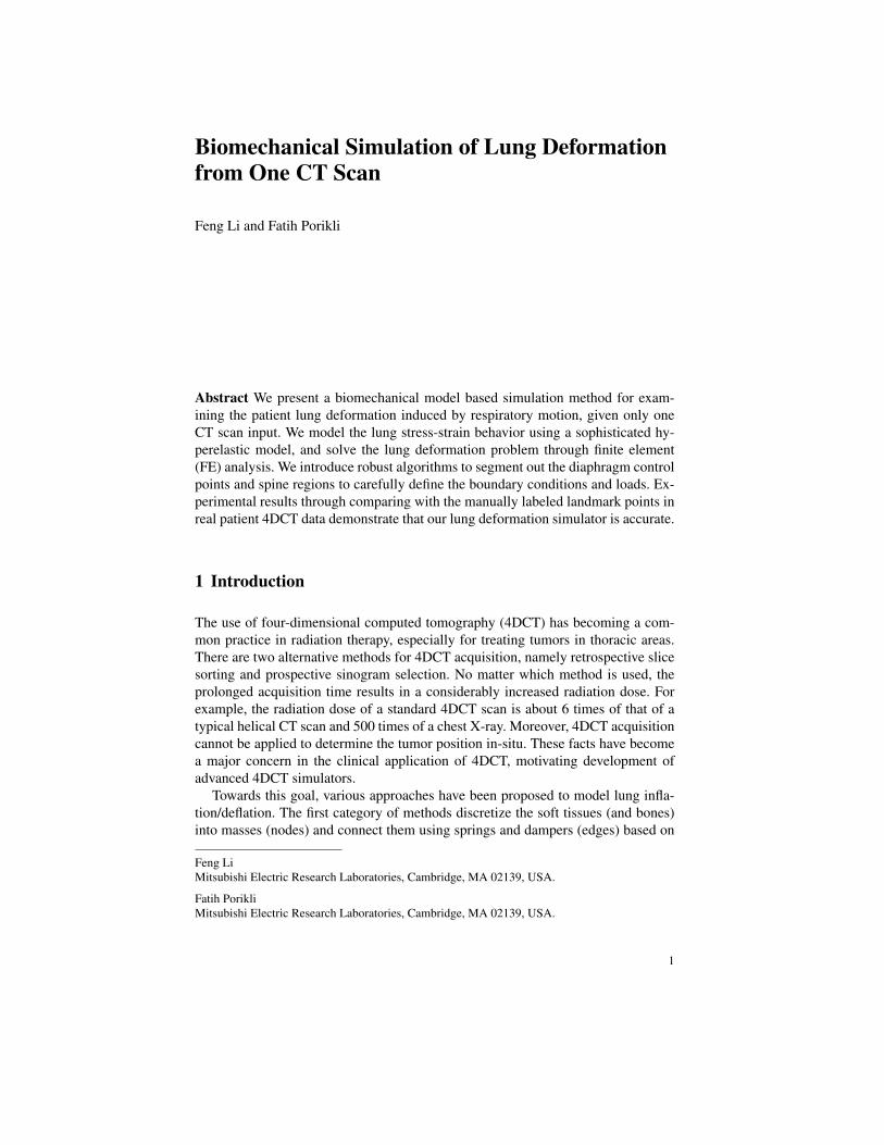
Fig. 1 Processing pipeline of our biomechanical simulation of lung deformations from one CTscan. The tetrahedra on the cutting plane of the volume mesh are colored in purple. Red pointsindicate imposed automatic boundary constraints.
algorithms. In the extended version of this paper, we also simulate the passive mass-spring model based deformation of abdominal organs due to lung inflation/deflation.Conversion from density to mass assumptions for mass-spring model are supportedby clinical data. To evaluate the accuracy of our simulator, we perform both qual-itative image visual examination and quantitative comparison on expert annotatedlung interior point pairs between multiple breathing phases, and demonstrate thatour biomechanical model based simulation is very accurate. Fig. 1 shows the pro-cessing pipeline of our 4DCT simulator based on biomechanical model.
4 Feng Li and Fatih Porikli
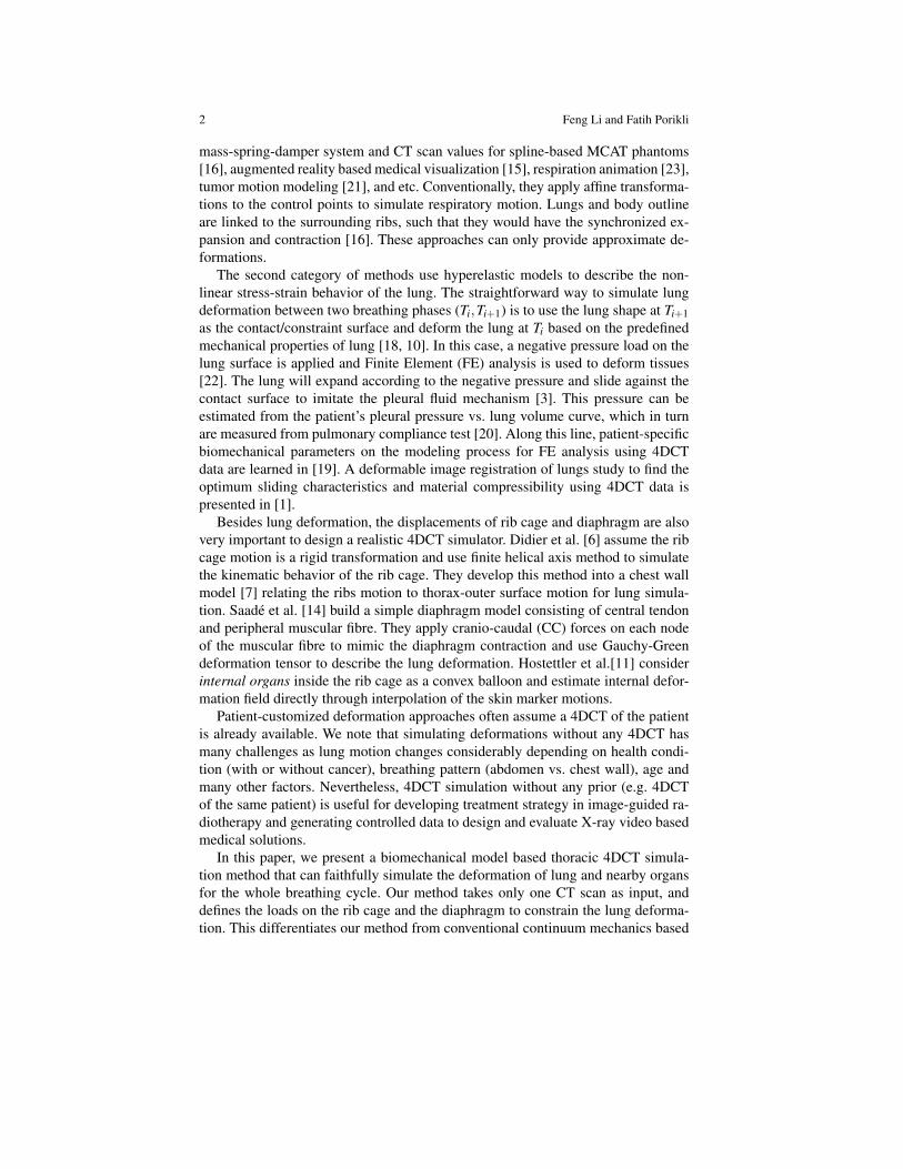
Fig. 2 Gaussian curve fitting for spine region estimation: (a)2D Gaussian curve fitting on a CTslice, (b) and (c) the different views of our 3D curve fitting results, and (d) final curve fitting resultafter outliers are removed.
2 Methods
2.1 Boundary Constraints Definition
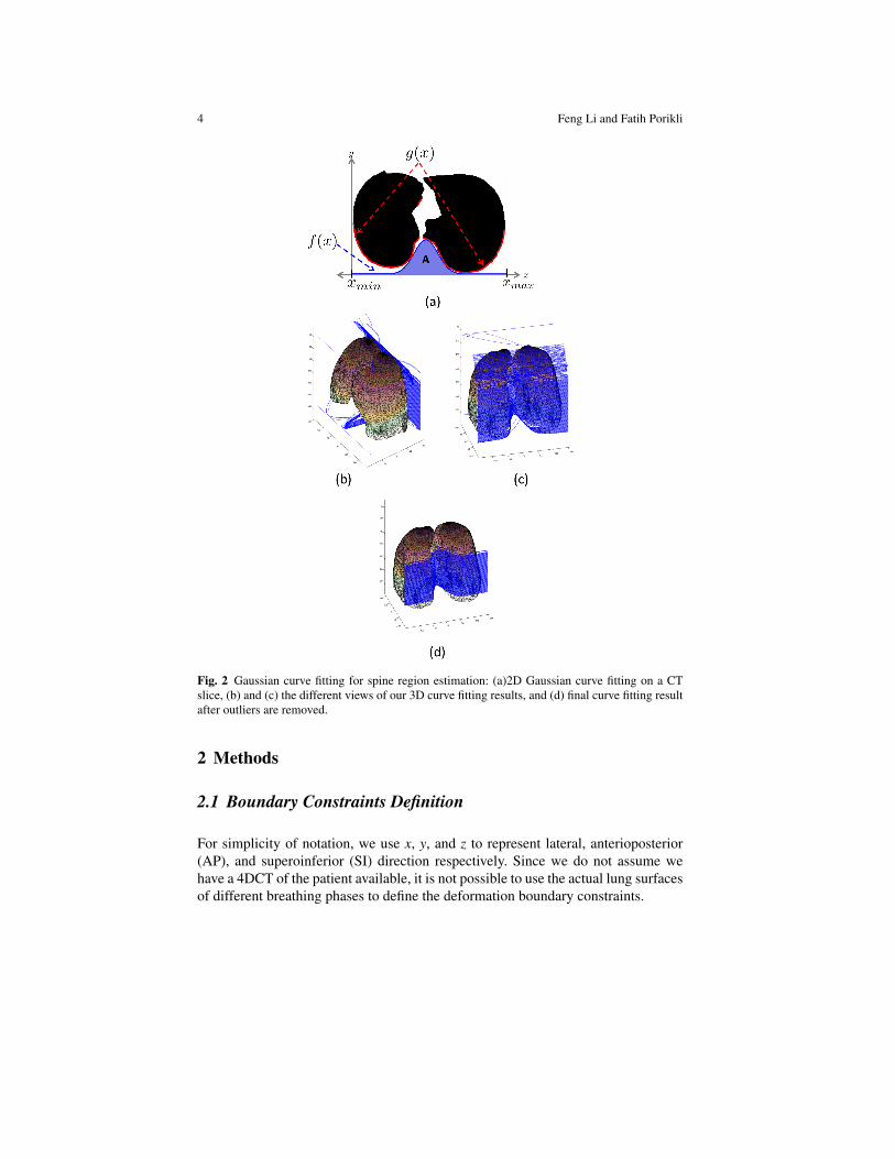
For simplicity of notation, we use x, y, and z to represent lateral, anterioposterior(AP), and superoinferior (SI) direction respectively. Since we do not assume wehave a 4DCT of the patient available, it is not possible to use the actual lung surfacesof different breathing phases to define the deformation boundary constraints.
Biomechanical Simulation of Lung Deformation from One CT Scan 5
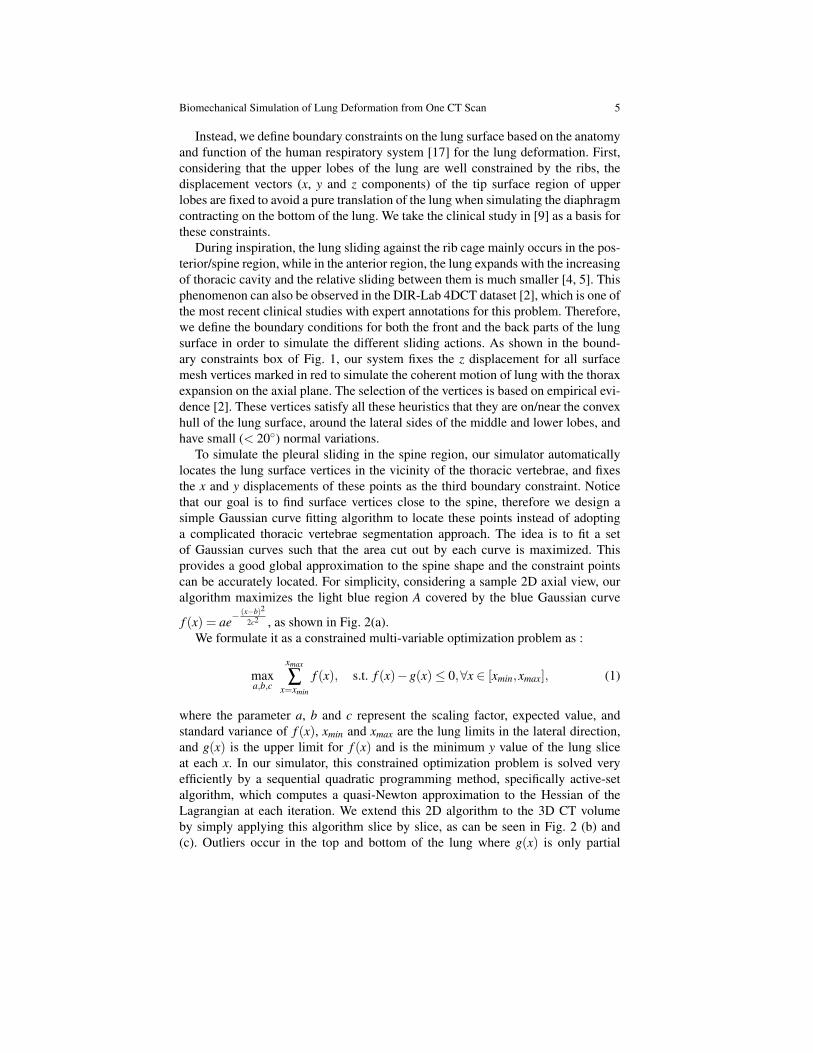
Instead, we define boundary constraints on the lung surface based on the anatomyand function of the human respiratory system [17] for the lung deformation. First,considering that the upper lobes of the lung are well constrained by the ribs, thedisplacement vectors (x, y and z components) of the tip surface region of upperlobes are fixed to avoid a pure translation of the lung when simulating the diaphragmcontracting on the bottom of the lung. We take the clinical study in [9] as a basis forthese constraints.
During inspiration, the lung sliding against the rib cage mainly occurs in the pos-terior/spine region, while in the anterior region, the lung expands with the increasingof thoracic cavity and the relative sliding between them is much smaller [4, 5]. Thisphenomenon can also be observed in the DIR-Lab 4DCT dataset [2], which is one ofthe most recent clinical studies with expert annotations for this problem. Therefore,we define the boundary conditions for both the front and the back parts of the lungsurface in order to simulate the different sliding actions. As shown in the bound-ary constraints box of Fig. 1, our system fixes the z displacement for all surfacemesh vertices marked in red to simulate the coherent motion of lung with the thoraxexpansion on the axial plane. The selection of the vertices is based on empirical evi-dence [2]. These vertices satisfy all these heuristics that they are on/near the convexhull of the lung surface, around the lateral sides of the middle and lower lobes, andhave small (< 20) normal variations.
To simulate the pleural sliding in the spine region, our simulator automaticallylocates the lung surface vertices in the vicinity of the thoracic vertebrae, and fixesthe x and y displacements of these points as the third boundary constraint. Noticethat our goal is to find surface vertices close to the spine, therefore we design asimple Gaussian curve fitting algorithm to locate these points instead of adoptinga complicated thoracic vertebrae segmentation approach. The idea is to fit a setof Gaussian curves such that the area cut out by each curve is maximized. Thisprovides a good global approximation to the spine shape and the constraint pointscan be accurately located. For simplicity, considering a sample 2D axial view, ouralgorithm maximizes the light blue region A covered by the blue Gaussian curve
f (x) = ae−(x−b)2
2c2 , as shown in Fig. 2(a).We formulate it as a constrained multi-variable optimization problem as :
maxa,b,c
xmax
∑x=xmin
f (x), s.t. f (x)−g(x)≤ 0,∀x ∈ [xmin,xmax], (1)
where the parameter a, b and c represent the scaling factor, expected value, andstandard variance of f (x), xmin and xmax are the lung limits in the lateral direction,and g(x) is the upper limit for f (x) and is the minimum y value of the lung sliceat each x. In our simulator, this constrained optimization problem is solved veryefficiently by a sequential quadratic programming method, specifically active-setalgorithm, which computes a quasi-Newton approximation to the Hessian of theLagrangian at each iteration. We extend this 2D algorithm to the 3D CT volumeby simply applying this algorithm slice by slice, as can be seen in Fig. 2 (b) and(c). Outliers occur in the top and bottom of the lung where g(x) is only partial
6 Feng Li and Fatih Porikli
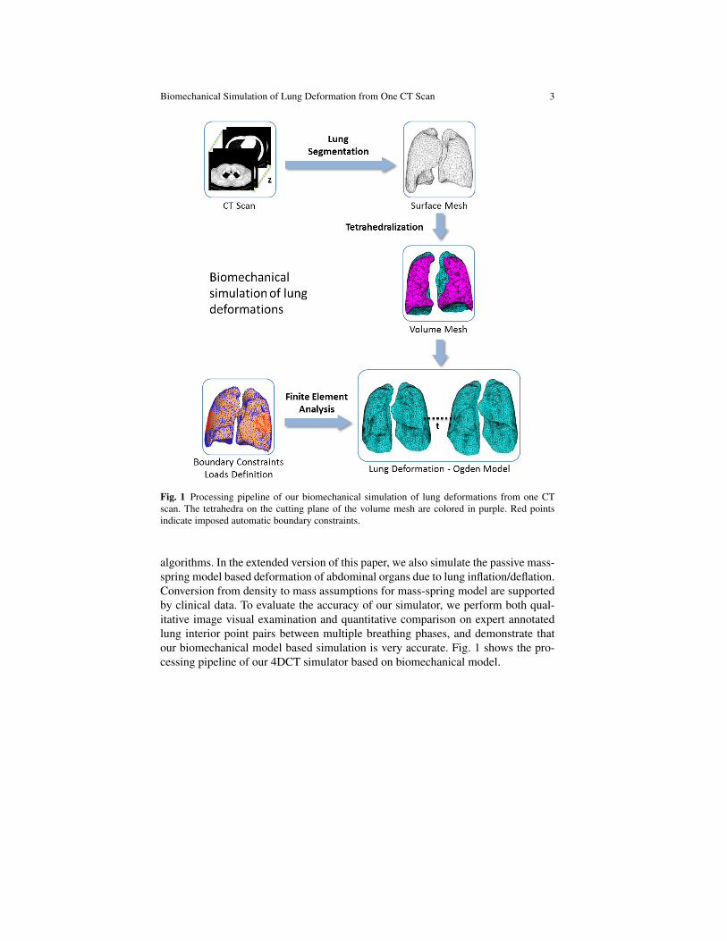
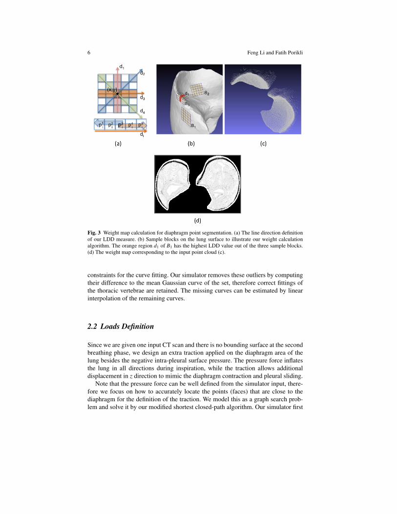
Fig. 3 Weight map calculation for diaphragm point segmentation. (a) The line direction definitionof our LDD measure. (b) Sample blocks on the lung surface to illustrate our weight calculationalgorithm. The orange region d1 of B1 has the highest LDD value out of the three sample blocks.(d) The weight map corresponding to the input point cloud (c).
constraints for the curve fitting. Our simulator removes these outliers by computingtheir difference to the mean Gaussian curve of the set, therefore correct fittings ofthe thoracic vertebrae are retained. The missing curves can be estimated by linearinterpolation of the remaining curves.
2.2 Loads Definition
Since we are given one input CT scan and there is no bounding surface at the secondbreathing phase, we design an extra traction applied on the diaphragm area of thelung besides the negative intra-pleural surface pressure. The pressure force inflatesthe lung in all directions during inspiration, while the traction allows additionaldisplacement in z direction to mimic the diaphragm contraction and pleural sliding.
Note that the pressure force can be well defined from the simulator input, there-fore we focus on how to accurately locate the points (faces) that are close to thediaphragm for the definition of the traction. We model this as a graph search prob-lem and solve it by our modified shortest closed-path algorithm. Our simulator first
Biomechanical Simulation of Lung Deformation from One CT Scan 7
computes a dense 3D point cloud by finding the lung voxels at every (x,y) loca-tion with the largest z value, as shown in Fig. 3(c), then converts the point cloudinto a weight map, Fig. 3(d), based on the local geometry information, and finallylocates the diaphragm points (Fig. 4(f)) through our modified shortest closed-pathalgorithm. The left and right lower lobe are treated separately.
Weight Map Definition: We consider the 3D point cloud as an 2D image withintensity value from the z value of the corresponding point, and run the local LineDirection Discrepancy (LDD) computation on this image to generate the weightmap W . Thus our weight map computation can also be viewed as a special type ofimage filtering. As shown in Fig. 3(a), for each line di(x,y) of a block centering at(x,y), we build up two sub-lines d1
i (x,y) and d2i (x,y) from (p3
i , p2i , p1
i ) and (p3i , p4
i ,p5
i ) respectively, (i = 1, . . . ,4), and compute the LDD as the minimum intersectionangle of the four sub-line pairs. Alternatively, we compute the maximum of the co-sine value of these angles to represent the weight, which can be efficiently calculatedthrough dot product as
W (p) = maxi=1,...,4
d1i ·d2
i
‖ d1i ‖ · ‖ d2
i ‖ , (2)
where p represents pixel position (x,y), and the block size is set as 5× 5 for sim-plicity. Intuitively, regions with high curvature would high/positive LDD value, forexample, d1 of B3 in Fig. 3(b), while flat regions would have low/negative LDDvalues, for instance, B1 and B2.
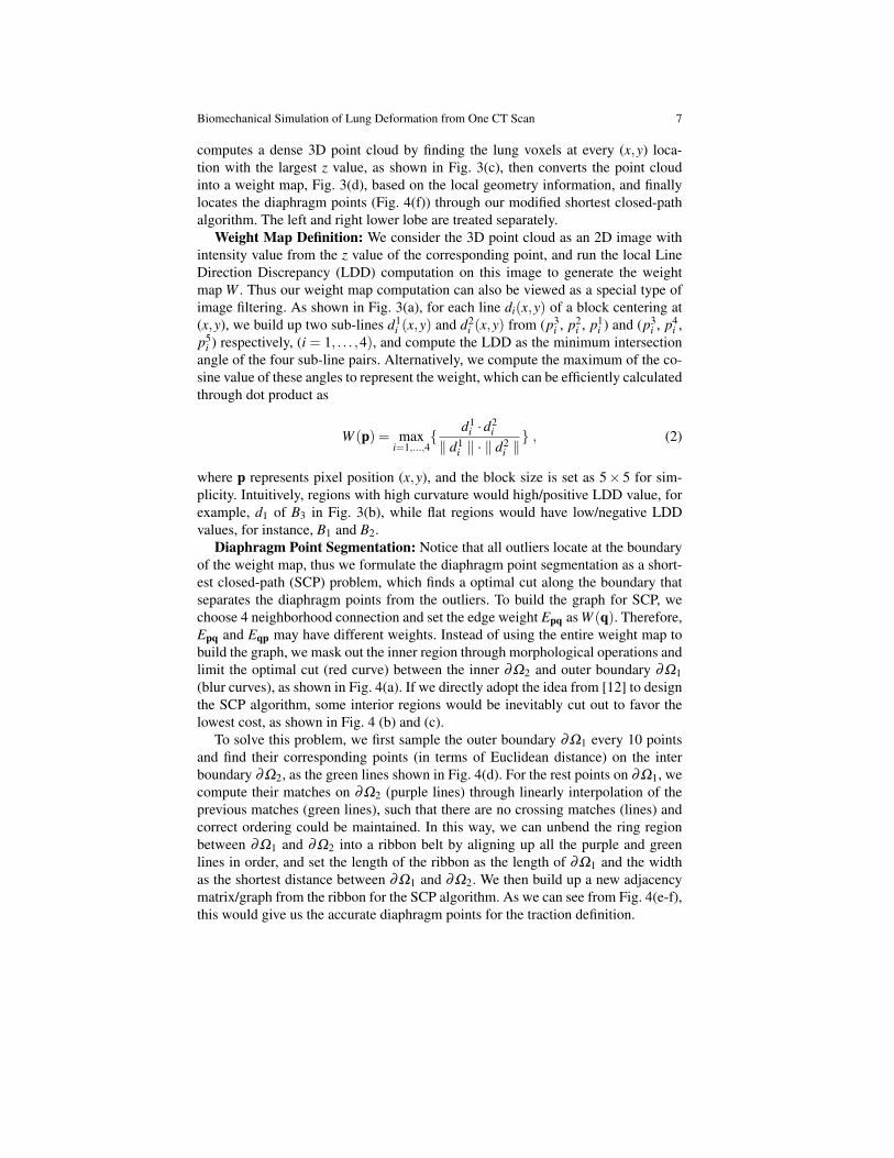
Diaphragm Point Segmentation: Notice that all outliers locate at the boundaryof the weight map, thus we formulate the diaphragm point segmentation as a short-est closed-path (SCP) problem, which finds a optimal cut along the boundary thatseparates the diaphragm points from the outliers. To build the graph for SCP, wechoose 4 neighborhood connection and set the edge weight Epq as W (q). Therefore,Epq and Eqp may have different weights. Instead of using the entire weight map tobuild the graph, we mask out the inner region through morphological operations andlimit the optimal cut (red curve) between the inner ∂Ω2 and outer boundary ∂Ω1(blur curves), as shown in Fig. 4(a). If we directly adopt the idea from [12] to designthe SCP algorithm, some interior regions would be inevitably cut out to favor thelowest cost, as shown in Fig. 4 (b) and (c).
To solve this problem, we first sample the outer boundary ∂Ω1 every 10 pointsand find their corresponding points (in terms of Euclidean distance) on the interboundary ∂Ω2, as the green lines shown in Fig. 4(d). For the rest points on ∂Ω1, wecompute their matches on ∂Ω2 (purple lines) through linearly interpolation of theprevious matches (green lines), such that there are no crossing matches (lines) andcorrect ordering could be maintained. In this way, we can unbend the ring regionbetween ∂Ω1 and ∂Ω2 into a ribbon belt by aligning up all the purple and greenlines in order, and set the length of the ribbon as the length of ∂Ω1 and the widthas the shortest distance between ∂Ω1 and ∂Ω2. We then build up a new adjacencymatrix/graph from the ribbon for the SCP algorithm. As we can see from Fig. 4(e-f),this would give us the accurate diaphragm points for the traction definition.
8 Feng Li and Fatih Porikli
Fig. 4 Diaphragm point segmentation. (a) Masked out the inner region: the inner ∂Ω2 and outerboundary ∂Ω1 (blue curves). (b) The optimal cut by conventional SCP algorithm (in red). (c) Theestimated diaphragm points. Our new SCP algorithm unbends the ring regions in (d) into ribbonbelts, and can accurately segment out the diaphragm points for traction definition in (e) and (f).
2.3 Finite Element Simulation
The final step for biomechanical simulation of lung deformation is to define thematerial property of the lung and apply FE analysis. We assume the lung tissue ishomogeneous, isotropic, and use the first-order Ogden model [13] to describe itsnon-linear strain energy density function as
W (λ1,λ2,λ3,J) =µ1
α1(λ α1
1 +λα12 +λ
α13 −3)+
K2(lnJ)2 , (3)
Biomechanical Simulation of Lung Deformation from One CT Scan 9
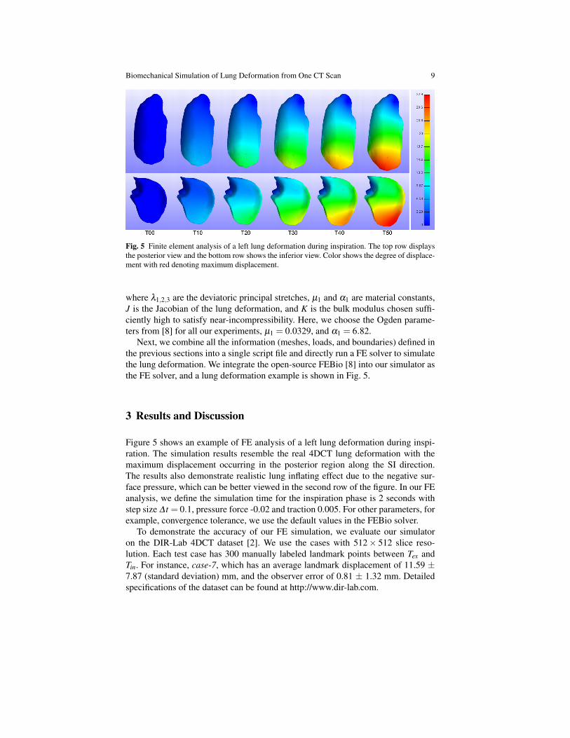
Fig. 5 Finite element analysis of a left lung deformation during inspiration. The top row displaysthe posterior view and the bottom row shows the inferior view. Color shows the degree of displace-ment with red denoting maximum displacement.
where λ1,2,3 are the deviatoric principal stretches, µ1 and α1 are material constants,J is the Jacobian of the lung deformation, and K is the bulk modulus chosen suffi-ciently high to satisfy near-incompressibility. Here, we choose the Ogden parame-ters from [8] for all our experiments, µ1 = 0.0329, and α1 = 6.82.
Next, we combine all the information (meshes, loads, and boundaries) defined inthe previous sections into a single script file and directly run a FE solver to simulatethe lung deformation. We integrate the open-source FEBio [8] into our simulator asthe FE solver, and a lung deformation example is shown in Fig. 5.
3 Results and Discussion
Figure 5 shows an example of FE analysis of a left lung deformation during inspi-ration. The simulation results resemble the real 4DCT lung deformation with themaximum displacement occurring in the posterior region along the SI direction.The results also demonstrate realistic lung inflating effect due to the negative sur-face pressure, which can be better viewed in the second row of the figure. In our FEanalysis, we define the simulation time for the inspiration phase is 2 seconds withstep size ∆ t = 0.1, pressure force -0.02 and traction 0.005. For other parameters, forexample, convergence tolerance, we use the default values in the FEBio solver.
To demonstrate the accuracy of our FE simulation, we evaluate our simulatoron the DIR-Lab 4DCT dataset [2]. We use the cases with 512× 512 slice reso-lution. Each test case has 300 manually labeled landmark points between Tex andTin. For instance, case-7, which has an average landmark displacement of 11.59 ±7.87 (standard deviation) mm, and the observer error of 0.81 ± 1.32 mm. Detailedspecifications of the dataset can be found at http://www.dir-lab.com.
10 Feng Li and Fatih Porikli
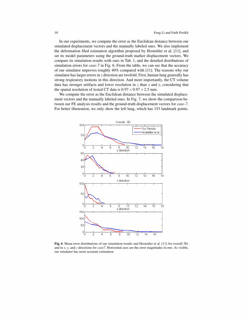
In our experiments, we compute the error as the Euclidean distance between oursimulated displacement vectors and the manually labeled ones. We also implementthe deformation filed estimation algorithm proposed by Hostettler et al. [11], andset its model parameters using the ground-truth marker displacement vectors. Wecompare its simulation results with ours in Tab. 1, and the detailed distributions ofsimulation errors for case-7 in Fig. 6. From the table, we can see that the accuracyof our simulator improves roughly 40% compared with [11]. The reasons why oursimulator has larger errors in z direction are twofold. First, human lung generally hasstrong respiratory motions in this direction. And more importantly, the CT volumedata has stronger artifacts and lower resolution in z than x and y, considering thatthe spatial resolution of tested CT data is 0.97×0.97×2.5 mm.
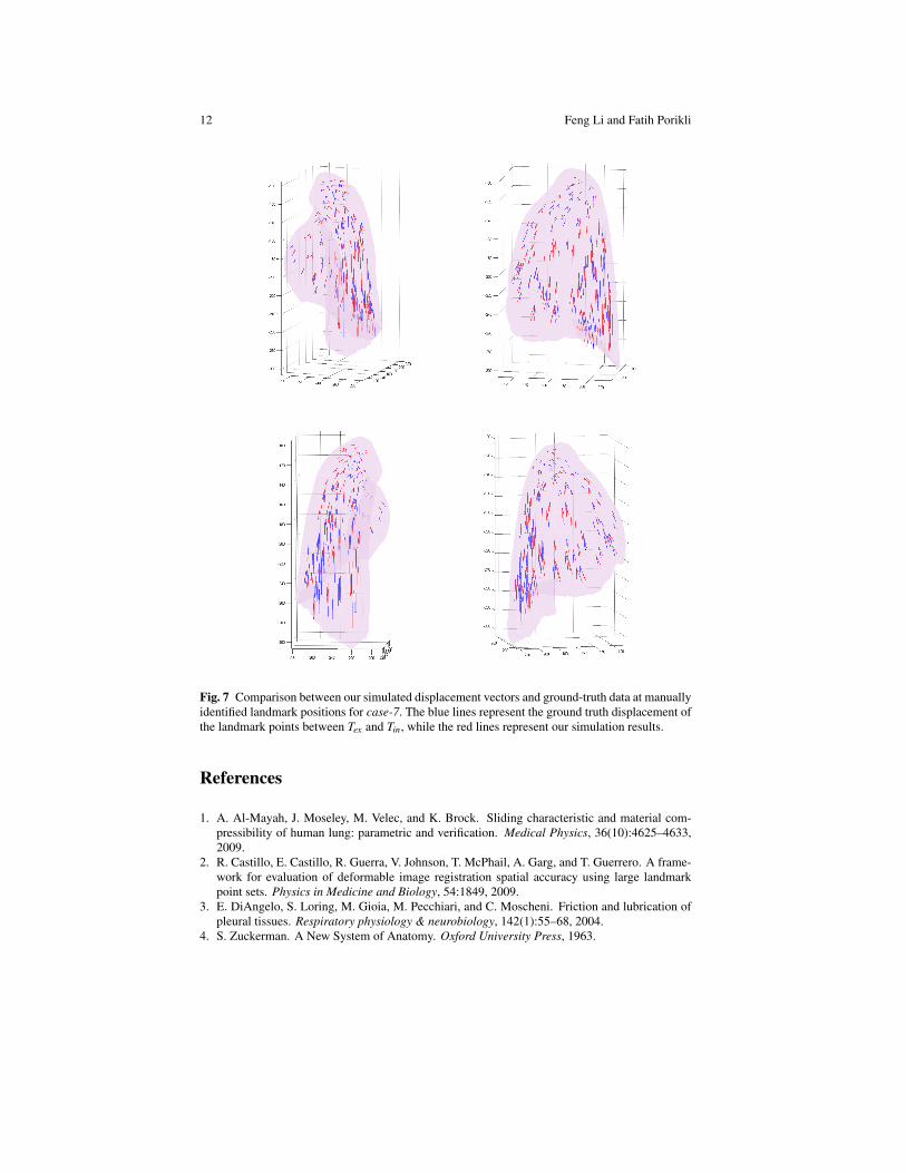
We compute the error as the Euclidean distance between the simulated displace-ment vectors and the manually labeled ones. In Fig. 7, we show the comparison be-tween our FE analysis results and the ground-truth displacement vectors for case-7.For better illustration, we only show the left lung, which has 153 landmark points.
Fig. 6 Mean error distributions of our simulation results and Hostettler et al. [11] for overall 3D,and in x, y, and z directions for case7. Horizontal axes are the error magnitudes in mm. As visible,our simulator has more accurate estimation.
Biomechanical Simulation of Lung Deformation from One CT Scan 11
Case ID CT Dims Our Results Hostettler et al.[11]case7 512×512×136 3.79 (1.80) 5.31 (3.35)case8 512×512×128 6.15 (3.31) 10.81 (4.69)case9 512×512×128 3.17 (1.37) 5.86 (1.83)case10 512×512×120 4.37 (2.95) 6.93 (2.86)
Table 1 Mean error (and standard deviation) of the deformed lungs measured in 3D space and itsx, y, and z components in mm. This table demonstrates that our biomechanical simulation algorithmfor lung deformation is accurate and performs better than [11] on tested DIR-Lab 4DCT datasets[2].
It can be seen that our simulator generates accurate results in the lower posteriorregion where the nodal displacement is mostly prominent. We observe that our sim-ulation results have some angular difference with the manually labeled data in theupper anterior region. That is partially due to lack of other prior force definitionsfor these elements in the simulator as it only uses the negative surface pressure. Be-sides, it is possible that the manually identified landmark points contain large errorssince nodal displacement in this region is less than or around the z spatial resolutionof the CT dataset.
We implement the deformation filed estimation algorithm proposed by Hostettleret al. [11], and set its model parameters using the ground-truth marker displacementvectors. We compare its simulation results with ours in Table 1. From the table,we can see that the accuracy of our simulator improves roughly 40% compared with[11]. As indicated by [2], these test cases have very different patient lung shapes, tu-mor sizes and locations, and breathing mechanisms. A simple interpolation betweenaxial lung envelopes adopted by Hostettler et al. [11] inevitably generates large er-rors while our algorithm adapts to different patients, thus achieves comparably moreaccurate results as shown in Table 1.
Our algorithm is a patient-customized lung deformation simulator. By provid-ing more sophisticated constraints, the simulation quality will improve further. Forinstance, the patient lung surface in case-8 is heavily curved in the back/posterior re-gion, thus including extra constraints to maintain this curved lung shape may makethe simulation more precise.
4 Conclusions
We have present a biomechanical model based lung simulation method for exam-ining the patient lung deformation induced by respiration given only one CT scaninput. We model the lung stress-strain behavior using a hyperelastic model, andsimulate the lung deformation by defining accurate boundary constraints and loads.Extensive analysis and comparisons with the manually labeled DIR-Lab datasetdemonstrate that our lung deformation results are accurate.
12 Feng Li and Fatih Porikli
Fig. 7 Comparison between our simulated displacement vectors and ground-truth data at manuallyidentified landmark positions for case-7. The blue lines represent the ground truth displacement ofthe landmark points between Tex and Tin, while the red lines represent our simulation results.
References
1. A. Al-Mayah, J. Moseley, M. Velec, and K. Brock. Sliding characteristic and material com-pressibility of human lung: parametric and verification. Medical Physics, 36(10):4625–4633,2009.
2. R. Castillo, E. Castillo, R. Guerra, V. Johnson, T. McPhail, A. Garg, and T. Guerrero. A frame-work for evaluation of deformable image registration spatial accuracy using large landmarkpoint sets. Physics in Medicine and Biology, 54:1849, 2009.
3. E. DiAngelo, S. Loring, M. Gioia, M. Pecchiari, and C. Moscheni. Friction and lubrication ofpleural tissues. Respiratory physiology & neurobiology, 142(1):55–68, 2004.
4. S. Zuckerman. A New System of Anatomy. Oxford University Press, 1963.
Biomechanical Simulation of Lung Deformation from One CT Scan 13
5. W. Norman. The Anatomy Lesson. Georgetown University, 1999.6. A. Didier, P. Villard, J. Bayle, M. Beuve, and B. Shariat. Breathing thorax simulation based on
pleura physiology and rib kinematics. IEEE International Conference on Medical InformationVisualisation-BioMedical Visualisation, 2007.
7. A. Didier, P. Villard, J. Saade, J. Moreau, M. Beuve, and B. Shariat. A chest wall model basedon rib kinematics. In IEEE International Conference on Visualisation, 2009.
8. B. Ellis, G. Ateshian, and J. Weiss. FEBio: Finite elements for biomechanics. Journal ofBiomechanical Engineering, 134(1):5–11, 2012.
9. J. Ehrhardt, R. Werner, T. Frenzel, W. Lu, D. Low, and H. Handels. Analysis of free breathingmotion using artifact reduced 4DCT image data. SPIE Medical Imaging Conference, 2007.
10. J. Eom, C. Shi, X. Xu, and S. De. Modeling respiratory motion for cancer radiation therapybased on patient-specific 4DCT data. MICCAI, 2009.
11. A. Hostettler, S. Nicolau, C. Forest, L. Soler, and Y. Remond. Real time simulation of or-gan motions induced by breathing: First evaluation on patient data. Biomedical SimulationConference, 2006.
12. J. Jia, J. Sun, C. Tang, and H. Shum. Drag-and-drop pasting. ACM SIGGRAPH Conference,2006.
13. R. Ogden. Large deformation isotropic elasticity-on the correlation of theory and experimentfor incompressible rubberlike solids. Proceedings of the Royal Society of London. Series A,Mathematical and Physical Sciences, 326(1567):565–584, 1972.
14. J. Saade, A. Didier, P. Villard, R. Buttin, J. Moreau, M. Beuve, and B. Shariat. A prelimi-nary study for a biomechanical model of the respiratory system. International Conference onComputer Vision Theory and Applications, 2010.
15. A. Santhanam, C. Fidopiastis, F. Hamza-Lup, J. Rolland, and C. Imielinska. Physically-baseddeformation of high-resolution 3d lung models for augmented reality based medical visualiza-tion. Medical Image Computing and Computer Aided Intervention, AMI-ARCS, pages 21–32,2004.
16. W. Segars, D. Lalush, and B. Tsui. Modeling respiratory mechanics in the MCAT and spline-based MCAT phantoms. IEEE Transactions on Nuclear Science, 48(1):89–97, 2001.
17. B. Vidiac and F. Suarez. Photographic atlas of the human body. CV Mosby (St. Louis), 1984.18. P. Villard, M. Beuve, B. Shariat, V. Baudet, and F. Jaillet. Simulation of lung behaviour with
finite elements: influence of biomechanical parameters. IEEE International Conference onMedical Information Visualisation-Biomedical Visualisation, 2005.
19. R. Werner, J. Ehrhardt, R. Schmidt, and H. Handels. Patient-specific finite element modelingof respiratory lung motion using 4DCT image data. Medical Physics, 36(5):1500–1511, 2009.
20. J. West. Respiratory physiology: the essentials. Lippincott Williams & Wilkins, 2008.21. P. Wilson and J. Meyer. A spring–dashpot system for modelling lung tumour motion in radio-
therapy. Computational and Mathematical Methods in Medicine, 11(1):13–26, 2010.22. T. Zhang, N. Orton, T. Mackie, and B. Paliwal. Technical note: A novel boundary condition
using contact elements for finite element based deformable image registration. Medical Physics,31(9):2412?2415, 2004.
23. V. Zordan, B. Celly, B. Chiu, and P. DiLorenzo. Breathe easy: model and control of simulatedrespiration for animation. Graphical Models, 68(2):113-132, 2006.