biomethane purification using pvdf/pebax 1657...
TRANSCRIPT

Journal of Physical Science, Vol. 28(Supp. 1), 39–51, 2017
© Penerbit Universiti Sains Malaysia, 2017
Biomethane Purification Using PVDF/Pebax 1657 Thin Film Composite Membrane
Mohamad Syafiq Abdul Wahab,1 Sunarti Abdul Rahman1* and Abdul Latif Ahmad2
1Faculty of Chemical Engineering and Natural Resources, Universiti Malaysia Pahang, 26300 Gambang, Pahang, Malaysia
2School of Chemical Engineering, Engineering Campus, Universiti Sains Malaysia, 14300 Nibong Tebal, Pulau Pinang, Malaysia
*Corresponding author: [email protected]
Published online: 15 February 2017
To cite this article: Abdul Wahab, M. S., Abdul Rahman, S. & Ahmad, A. L. (2017). Biomethane purification using PVDF/Pebax 1657 thin film composite membrane. J. Phys. Sci., 28(Supp. 1), 39–51, https://doi.org/10.21315/jps2017.28.s1.3
To link to this article: https://doi.org/10.21315/jps2017.28.s1.3
ABsTrACT: Biogas is an alternative energy from biomass. The gas can be produced from anaerobic digestion by microorganism. Biomasses such as animal manure, kitchen waste, garden waste, or even human excreta are among the major sources of biogas. Usually, biogas contains 60% methane along with 40% of carbon dioxide. Besides its important role in natural gas, methane also contributes to greenhouse gases. Their presence in atmosphere will thicken earth blanket and further lead to climate change. One pound of methane traps 25 times more heat in the atmosphere compared to one pound of carbon dioxide. This research introduced a new material, Pebax 1657 to improve the current polymeric based membranes in the form of thin film composite (TFC). Polyvinylidene fluoride (PVDF) was used as a porous support layer for this TFC and this combination surpassed the Robeson 2008 trade off limit with CO2 pressure normalise flux and selectivity of 1075 Barrer and 52.50 respectively. Besides transforming the waste into wealth, the emission of this greenhouse gases can be reduced so that a green environment and clean air can be continually enjoyed by future generations.
Keywords: PEBAX, PVDF, composite membrane, coating method, CO2/ CH4 separation

Biomethane Purification Using TFC Membrane 40
1. INTrODUCTION
Energy sources are divided into two sub categories, namely primary and secondary energy sources. The sources of energy are classified based on the derivation of usable energy. In general, the primary energy sources can be used directly as they are found in natural environment. Coal, oil, natural gas, water, wind and oil are among the primary sources.1 Secondary sources are derived from the transformation of primary energy sources, such as petrol, which is derived from treatment of crude oil and electric energy, and obtained from the conversion of mechanical energy such as hydroelectric plants. Biogas is a renewable energy derived from the primary sources, biomass. Several processes to transform biomass into secondary energy sources include combustion, thermochemical transformation, physical-chemical transformation and biochemical transformation.2 Anaerobic fermentation of biomass into biogas which is rich in methane, CH4 are widely used in European countries where every farmer has their own anaerobic digester to yield CH4 from their farm waste such as animal manure and agriculture waste. Usually, biogas contains 60% of CH4 and 40% of carbon dioxide, CO2 with several amounts of impurities. The specific properties of biogas are tabulated in Table 1.
Table 1: General features of biogas.
Composition55%–70% CH4
30%–45% CO2
Traces of other gases
Energy content 6.0–6.5 kWh m–3
Fuel equivalent 0.60–0.65 l oil m–3 biogas
Explosion limits 6%–12% biogas in air
Ignition temperature 650–750°C
Critical pressure 75–89 bar
Critical temperature –82.5°C
Normal density 1.2 kg m–3
Smell Bad eggs
Molar mass 16.043 kg kmol–1
Where energy sources are concerned, the dependency of methane from natural gas can be reduced by purification of bio-methane from biogas. High amount of CH4 from the biogas composition can be both profitable and environmentally beneficial. The purification of this so-called "waste to wealth" gas can reduce the emission of CO2 and CH4 gases to atmosphere, as landfill is among the sources of biogas or often called landfill gas (LFG). One pound of CH4 can hold 25 times more heat in

Journal of Physical Science, Vol. 28(Supp. 1), 39–51, 2017 41
atmosphere compared to CO2 and they create a perfect heat blanket to our mother earth, thus causing climate change. Among 296 landfill sites in Malaysia, only 165 sites are properly managed as indicated in Table 2. The cost of waste management including collection and transportation to dispose in a landfill site varies between RM90 and RM150 per ton and Malaysia generates approximately around 17,000 to 18,000 tons of waste daily, which is about RM2 million in costs per day.
Table 2: Numbers of landfill site in Malaysia for each state.
State Operational landfill Non-operation landfill site Total
Johor 14 23 37
Kedah 8 7 15
Kelantan 13 6 19
Melaka 2 5 7
Negeri Sembilan 7 11 18
Pahang 16 16 32
Perak 17 12 29
Perlis 1 1 2
Pulau Pinang 2 1 3
Sabah 19 2 21
Sarawak 49 14 63
Selangor 8 14 22
Terengganu 8 12 20
W. P. Kuala Lumpur 0 7 7
W. P. Labuan 1 0 1
Total 165 131 296
Proper management of landfill by securing the LFG and further purification could be a turning point as the price of purified methane is competitively high compared to natural gas. Delkash et al. stated that landfill methane emission is not consistent because of dependency on several factors such as waste disposal rates, type of sources, meteorological and atmospheric condition.3 In addition, microbial activities are strongly influenced by soil temperature and moisture for digestion process and gas transport in soil.3 The answer to this problems is through organic-inorganic waste sorting and treating the organic waste in a build digester system, so that all parameters can be manipulated to yield the highest amount of methane. Ordinary digester can yield approximately 20 m3 of biogas and some can yield up to 800 m3 per ton of waste. This depends on the anaerobic digester design and waste quality.4

Biomethane Purification Using TFC Membrane 42
Purification of methane from LFG or biogas will benefit the environment, and can optimally cover the waste management cost. Several techniques can be used for bio-methane purification such as cryogenic distillation, pressure swing adsorption (PSA), and membrane separation. In this research, polymeric membrane separation has been chosen as a feasible method based on several criteria: small footprint, low capital and operating costs, environmentally friendly, and exhibiting good process flexibility.5 The flexibility of polymeric membranes comes with a price since their highly permeable structure suffers loss in gas selectivity.
The objective of this work is to prepare and study the effectiveness of PVDF/Pebax 1657 TFC over PVDF film for biomethane purification by testing the produced membrane via single gas (CO2 and CH4) permeation method to find the ideal selectivity. Pebax 1657 is introduced in this research as a selective layer due to its excellent CO2 adsorbent.6,7 The unique structure of the elastomer combines both mechanical stability of the polyamide and the soft segment of polyether which act as a separation channel. This combination is believed to be able to improve the permeability-selectivity of PVDF membranes.
2. EXPErIMENTAL
2.1 Materials
Pallet of analytical grade PVDF with 177°C melting temperature was purchased from Sigma Aldrich. Pebax 1657 with 60% polyether and 40% polyamide contents, which is suitable for coating layer, was purchased from Arkema France. Two solvents are used in this study, which are ethanol and N-methyl-2-pyrrolidone (NMP), supplied by Fisher Scientific. Purified CO2 and CH4 gases were used for gas permeation and separation performance. PVDF and Pebax 1657 were dried at 60°C for at least 24 h before the dope preparation.
2.2 Membranes Fabrication
2.2.1 PVDF substrate
The dope solution was prepared by diluting 15 wt% PVDF pellet in NMP and stirred uniformly at 80°C for about 7 h until all the pallets dissolved. The choice of diluting temperature must be below the NMP boiling point to avoid the vaporisation of the solvent. The PVDF dope solution was then degassed by leaving it at room temperature for 24 h to achieve a bubble-free solution. The solution was cast on

Journal of Physical Science, Vol. 28(Supp. 1), 39–51, 2017 43
a glass plate at room temperature with a casting machine having thickness of 0.03 mm before submerged in a water bath for 2 h and subsequently dried at room temperature for 24 h.8
2.2.2 Thin film composite membrane
3 wt% of Pebax 1657 was dissolved in a combination of 70/30 ethanol/water at 80°C for 3 h until a homogenous clear and diluted solution was obtained. This Pebax 1657 coating solution was left at room temperature for 24 h before it was coated on the PVDF substrate by using dip-coating technique. Pebax 1657 was coated on the PVDF substrate for 1, 2, 3 and 4 times where every coating of the TFC was dried at 60°C for 15 min to let the solvent vaporise. For extra vaporisation of the solvent, the TFC was further dried at 60°C for 12 h. To further study the effectiveness of the Pebax 1657, the coating solution was manipulated from 1% to 5% which later dip coated with PVDF film according to the best layer found earlier.
2.3 Permeability Test
The permeability test was conducted according to Ahmad et al. where each gas of CO2 and CH4 was tested individually by allowing them to flow at 2 bar toward the membrane cell and the flowrate of permeate was measured by the bubble flow meter as shown in Figure 1.9 Equation 1 was used to calculated the gas permeance and it was expressed in Barrer [1 Barrer = 1 × 10⁻¹⁰ cm3 (STP) cm/(cm2scmHg)]. By taking the conversion factor in account, Equation 2 can be directly used to find the gas permeance in Barrer.
P = lV
(cm3 cm(stp))/ (cm2 scmHg) (1)Atδp
P (Barrer) = 1×10¹⁰ lV (2)
Atδp
where P is the permeability, l the thickness of the membrane in cm, A the effective membrane area in cm2, V the volume in cm3 displaced in time t(s), and p the transmembrane pressure expressed in cm cmHg. The membrane selectivity is the membrane ability to separate two gases (A and B). It is the ratio of permeability A and B (Equation 3).
αAB = PA (3)PB

Biomethane Purification Using TFC Membrane 44
Figure 1: Gas permeability experimental set up.
2.4 Membrane Characterisation
To detect the presence of chemical added to the TFC, Fourier transform infrared spectroscopy (FTIR) was used. The TFC was allowed to absorb different kinds of wavelength produced from a beam in which the output data comes out in the form of wavenumbers, cm–1. To study the morphological structure of the TFC, the sample was first frozen and fractured in liquid nitrogen to get the smooth cutting without any part of the membrane blocking the cutting surface for scanning electron microscope (SEM) analysis. The sample was then flushed with nickel coating to avoid any charge building up from the electron beam, which is often called the space charge effect during surface imaging.10
3. rEsULTs AND DIsCUssION
3.1 Membranes Morphology
The cross sectional SEM image of PVDF film can be seen in Figure 2 and PVDF/Pebax 1657 TFC in Figure 3. The film exhibits an asymmetric structure with combination of spongy porous layer and microvoid formation. The formation of top finger-like voids is believed due to instantaneous phase inversion during solvent-non solvent liquid-liquid demixing in water bath. The rapid movement of NMP coming out from the film left a large void and was followed by spongy porous at the bottom. This kind of structure will boost gas permeability for gas

Journal of Physical Science, Vol. 28(Supp. 1), 39–51, 2017 45
Figure 2: SEM image of PVDF film.
(a)
(c)
(b)
(d)
Figure 3: SEM image of PVDF/Pebax 1657 TFC, (a) 1-layer Pebax 1657, (b) 2-layer Pebax 1657, (c) 3-layer Pebax 1657, and (d) 4-layer Pebax 1657.

Biomethane Purification Using TFC Membrane 46
transportation through the film; however, it results in loss in selectivity. The TFC was successfully made by varying the number of coating times to form different thickness of Pebax 1657 selective layer (see Figure 4).
From the SEM analysis, the thickness of sample a, b, c and d was found to be 4 µm, 15.3 µm, 33.3 µm, and 46.7 µm respectively. The TFC also has smaller voids compared to the PVDF film possibly due to polymer compaction effect during coating procedure as the top layer gave a slight pressure throughout the process. The pore diameters also show a noticeable change with the PVDF film pores ranging from 0.9 µm to 2.2 µm while the TFC exhibits a very narrow pores structure which is below than 1 µm. This observation is attributed to the crystallisation of PVDF during the oven drying of TFC as researchers agree that solvent evaporation and temperature are among the factors that cause modification of polymeric chains.11
3.2 Chemical Characterisation
All samples exhibit the same functional group through presence of a chain of several bonds which lead to PVDF whereas samples B, C and D show another extra peak of Pebax coating layer on top of PVDF. Figure 4 shows the chemical structure of both PVDF and Pebax 1657 which was later used as a reference to the bonding structure represented by the wavenumbers in Figure 5. CH2 deformation of PVDF molecules for all samples was detected as a strong bending vibration in range of 1350–1470 cm–1, while the fluoride which formed the alkyl halide, C-F of the compound was spotted around 1000–1400 cm–1 with a strong stretching vibration.11–13 Pebax 1657 was detected through several molecule bonding starting with ether stretching (C-O) and nylon-6 with the stretching of N-H at 1000–1300 cm–1 and 3300 cm–1 respectively.14 The amide segment of the elastomer was transmitted with the stretching of C=O at 1640 cm–1.15,16 Other peaks in the spectrum of the composite membrane at 2869–2939 cm–1 can be attributed to the asymmetric and symmetric stretching of the C-H bond.17
3.3 Effect of Pebax 1657 Coating Thickness on TFC
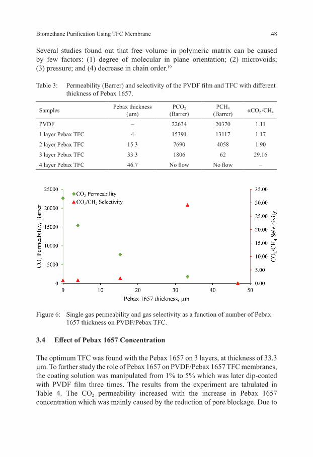
As the objective of the study is to find the best thickness for PVDF/Pebax 1657 TFC for bio-methane purification, the effectiveness of the selective layer has been tested using single gas permeation. The results from the experiment are tabulated in Table 3. The CO2 permeability and CO2/CH4 selectivity has been plotted as a function of Pebax thickness in Figure 6. As a reference, uncoated PVDF film was tested first so that the difference in CO2 permeability and gas selectivity can be targeted as the effect of the coating layer made. The original uncoated PVDF film has an almost equal CO2-CH4 permeability values which are 22634 and 20370

Journal of Physical Science, Vol. 28(Supp. 1), 39–51, 2017 47
respectively with CO2 /CH4 selectivity of 1.11. The low gas selectivity may be due to the large void that later created a large free volume in polymeric chain, therefore influencing the rate of gas transportation through the membranes. Increase in the number of selective layer thickness from 1 layer to 2 slightly improved the gas selectivity from 1.17 to 1.90 but the TFC lost its capacity to selectively transport the two gases. The optimum layer of the TFC was found to be 3 with 33.3 µm Pebax 1657 thickness and no gas flow was detected when it comes to the last sample with 4 layers of Pebax 1657.
The trend of gas permeability for both gases is the same. With the increase in the coating layer, the gas permeability decreases as a result of slow rate of gas diffusing through the membranes. This gas transportation behaviour is believed due to the decrease in membrane free volume within the polymeric chain as the crystallinity of the soft segment of polyamide might increase with the thickness. The crystalline segment of polymer is also impermeable towards penetrants.18
Figure 4: Chemical structure of (a) PVDF and (b) Pebax 1657.
Figure 5: FTIR spectra of A (PVDF), B, C and D representing TFC with Pebax 1657 1, 2 and 3 layers respectively.
Biomethane Purification Using TFC Membrane 48
Several studies found out that free volume in polymeric matrix can be caused by few factors: (1) degree of molecular in plane orientation; (2) microvoids; (3) pressure; and (4) decrease in chain order.19
Table 3: Permeability (Barrer) and selectivity of the PVDF film and TFC with different thickness of Pebax 1657.
Samples Pebax thickness(µm)
PCO2
(Barrer)PCH4
(Barrer) αCO2 /CH4
PVDF – 22634 20370 1.11
1 layer Pebax TFC 4 15391 13117 1.17
2 layer Pebax TFC 15.3 7690 4058 1.90
3 layer Pebax TFC 33.3 1806 62 29.16
4 layer Pebax TFC 46.7 No flow No flow –
Figure 6: Single gas permeability and gas selectivity as a function of number of Pebax 1657 thickness on PVDF/Pebax TFC.
3.4 Effect of Pebax 1657 Concentration
The optimum TFC was found with the Pebax 1657 on 3 layers, at thickness of 33.3 µm. To further study the role of Pebax 1657 on PVDF/Pebax 1657 TFC membranes, the coating solution was manipulated from 1% to 5% which was later dip-coated with PVDF film three times. The results from the experiment are tabulated in Table 4. The CO2 permeability increased with the increase in Pebax 1657 concentration which was mainly caused by the reduction of pore blockage. Due to

Journal of Physical Science, Vol. 28(Supp. 1), 39–51, 2017 49
presence of large voids and free volume in PVDF substrate, the lower Pebax 1657 concentration made the solution very dilute and penetrated deep into membranes matrix. The viscosity of Pebax solution plays a big role in avoiding defect in the PVDF/Pebax 1657 TFC. The performance of this TFC is illustrated in Figure 7 where it falls beyond the Robeson upper bound. From the curve, the effectiveness of the dense Pebax 1657 layer increases with increasing Pebax concentration.17
Table 4: CO2 permeability and CO2 /CH4 selectivity based on different concentration of Pebax 1657 coating solution.
Pebax concentration, % PCO2 αCO2 /CH4
1 429 1.94
2 2686 23.13
3 1806 29.16
4 1433 33.33
5 1075 52.50
Figure 7: Robeson upper bound 2008 of CO2 /CH4 selectivity against CO2 permeability.
4. CONCLUsION
Thin film composites, TFC membranes of PVDF and Pebax 1657, have been successfully developed using dry/wet phase inversion techniques for the PVDF substrate, and dip coating technique for the TFC. The SEM characterisations

Biomethane Purification Using TFC Membrane 50
reveal that different selective layer thicknesses of Pebax 1657 were formed based on different number of coatings made on the PVDF film. By having the selective layer, the CO2 permeability and gas selectivity of the original uncoated PVDF film have also been improved. The FTIR analysis confirmed that only PVDF and Pebax structures were present on the TFC. The optimum number of layer was found to be 3 with thickness of 33.3 µm which gave CO2 permeability and gas selectivity of 1806 and 29.16 respectively. With the increase in Pebax 1657 concentration, the fabricated TFC surpassed the Robeson upper boundary to overcome the polymeric membranes trade-off limits with CO2 permeability of 1075 and CO2/CH4 selectivity of 52.50. To have a good TFC, the selective layer must not be too thin and the coating solution must also not be too diluted as they would cause defects in the TFC.
5. ACKNOWLEDGEMENTs
The authors wish to thank Universiti Malaysia Pahang (UMP) grant (RDU 150311) and Long-term Research Grant Scheme (LRGS) grant (RDU150901), and the Faculty of Chemical and Natural Resources Engineering, UMP for the gas engineering lab facilities.
6. rEFErENCEs
1. Deublein, D. A. (2008). Biogas from waste and renewable resources. Weinheim: Wiley-VCH.
2. Blaschek, H., Ezeji, T. & Scheffran, J. (2010). Biofuels from agricultural wastes and byproducts. Iowa: Wiley-Blackwell.
3. Delkash, M., Zhou, B. & Singh, R. (2016). Measuring landfill methane emissions using satellite and ground data. Remote Sens. Appl. Soc. Environ., 4, 18–29.
4. Electrigaz.com. (2016). Biogas FAQ. Retrieved 25 May 2016 from http://electrigaz.com/faq_en.htm
5. He, X., Kim, T. & Hägg, M. (2014). Hybrid fixed-site-carrier membranes for CO2 removal from high pressure natural gas: Membrane optimization and process condition investigation. J. Membr. Sci., 470, 266–274, https://doi.org/10.1016/j.memsci.2014.07.016.
6. Jomekian, A. et al. (2016). Utilization of Pebax 1657 as structure directing agent in fabrication of ultra-porous ZIF-8. J. Solid State Chem., 235, 212–216, http://dx.doi.org/10.1016/j.jssc.2016.01.004.

Journal of Physical Science, Vol. 28(Supp. 1), 39–51, 2017 51
7. Jomekian, A. et al. (2016). CO2/CH4 separation by high performance co-casted ZIF-8/Pebax 1657/PES mixed matrix membrane. J. Nat. Gas Sci. Eng., 31, 562–574, https://doi.org/10.1016%2Fj.jngse.2016.03.067.
8. Wahab, M., Sunarti, A. R. & Farhana, D. N. (2016). Preliminary investigation on gas separation ability of polysulfone/pebax 1657 composite membrane. J. Teknol., 78(11), 155–160.
9. Ahmad, A. et al. (2009). Development of thin film composite for CO2 separation in membrane gas absorption application. Asia Pac. J. Chem. Eng., 4, 787–792, https://doi.org/10.1002/apj.339.
10. Mittal, K. (1989). Particles on surfaces 2. New York: Plenum Press.11. Freire, E. et al. (2012). Non-isothermal crystallization of PVDF/PMMA
blends processed in low and high shear mixers. J. Non-Cryst. Solids, 358, 2674–2681, https://doi.org/10.1016/j.jnoncrysol.2012.06.021.
12. Wang, J. et al. (2016). Fabrication of hydrophobic flat sheet and hollow fiber membranes from PVDF and PVDF-CTFE for membrane distillation. J. Membr. Sci., 497, 183–193, https://doi.org/10.1021/ie102012v.
13. Wang, Z. et al. (2015). Preparation and catalytic property of PVDF composite membrane with polymeric spheres decorated by Pd nanoparticles in membrane pores. J. Membr. Sci., 496, 95–107, https://doi.org/10.1016%2Fj.memsci.2015.08.041.
14. Efome, J. et al. (2015). Effects of superhydrophobic SiO2 nanoparticles on the performance of PVDF flat sheet membranes for vacuum membrane distillation. Desalin., 373, 47–57.
15. Wang, S. et al. (2014). Pebax–PEG–MWCNT hybrid membranes with enhanced CO2 capture properties. J. Membr. Sci., 460, 62–70, https://doi.org/10.1016/j.memsci.2014.02.036.
16. Li, Y. et al. (2015). Anionic surfactant-doped Pebax membrane with optimal free volume characteristics for efficient CO2 separation. J. Membr. Sci., 493, 460–469, https://doi.org/10.1016/j.memsci.2015.06.046.
17. Esposito, E. et al. (2015). Pebax®/PAN hollow fiber membranes for CO2 /CH4 separation. Chem. Eng. Process., 94, 53–61.
18. Islam, M. & Buschatz, H. (2005). Assessment of thickness-dependent gas permeability of polymer membranes. Indian J. Chem. Technol., 12, 88–92.
19. Flaconneche, B., Martin, J. & Klopffer, M. (2001). Permeability, diffusion and solubility of gases in polyethylene, polyamide 11 and poly (vinylidene fluoride). Oil Gas Sci. Technol., 56, 261–278.
