bladecenter type 8677: planning and installation...
TRANSCRIPT

BladeCenter
Type
8677
Planning
and
Installation
Guide
GA27-4327-01
ERserver
���


BladeCenter
Type
8677
Planning
and
Installation
Guide
GA27-4327-01
ERserver
���

Note:
Before
using
this
information
and
the
product
it
supports,
read
the
general
information
in
Appendix
C,
“Notices,”
on
page
107.
Second
Edition
(August
2003)
©
Copyright
International
Business
Machines
Corporation
2003.
All
rights
reserved.
US
Government
Users
Restricted
Rights
–
Use,
duplication
or
disclosure
restricted
by
GSA
ADP
Schedule
Contract
with
IBM
Corp.

Preface
This
book
is
intended
for
anyone
who
plans
for
the
physical
installation
and
configuration
of
an
IBM®
ERserver
BladeCenter™
unit.
This
book
is
organized
as
follows
and
should
be
used
for
these
tasks:
v
Use
Chapter
1,
“Introducing
the
BladeCenter
unit,”
on
page
1
to
understand
the
overall
purpose
and
usage
of
BladeCenter
units
and
blade
servers.
v
Use
Chapter
2,
“BladeCenter
unit
components,”
on
page
9
to
learn
about
the
physical
components
that
make
up
a
BladeCenter
unit.
v
Use
Chapter
3,
“Deployment
considerations,”
on
page
21
to
learn
about
network
topology
considerations
and
deployment
considerations.
v
Use
Chapter
4,
“Installation
considerations,”
on
page
41
and
Appendix
A,
“Planning
worksheets,”
on
page
85
to
plan
for
the
physical
environment
for
installing
BladeCenter
units.
This
includes,
space,
power,
cooling
and
cabling.
The
worksheets
provide
the
basis
for
selecting
the
features
and
options
for
each
blade
server,
where
the
blade
server
is
installed
in
a
BladeCenter
unit
and
a
rack
location
for
each
BladeCenter
unit.
v
Use
Chapter
5,
“Configuration
considerations,”
on
page
73
and
Appendix
B,
“Configuration
Worksheets,”
on
page
95
to
plan
for
the
configuration
of
the:
–
management
module
–
Ethernet
switch
modules
–
Fibre
channel
switch
modules
–
Blade
servers.
©
Copyright
IBM
Corp.
2003
iii

iv
BladeCenter
Type
8677:
Planning
and
Installation
Guide

Contents
Preface
.
.
.
.
.
.
.
.
.
.
.
.
.
.
.
.
.
.
.
.
.
.
.
.
.
.
.
. iii
Chapter
1.
Introducing
the
BladeCenter
unit
.
.
.
.
.
.
.
.
.
.
.
.
. 1
Why
choose
the
BladeCenter
technology?
.
.
.
.
.
.
.
.
.
.
.
.
.
.
. 1
What
the
BladeCenter
unit
offers
.
.
.
.
.
.
.
.
.
.
.
.
.
.
.
.
.
. 1
BladeCenter
unit
features
.
.
.
.
.
.
.
.
.
.
.
.
.
.
.
.
.
.
.
. 3
Why
blade
servers?
.
.
.
.
.
.
.
.
.
.
.
.
.
.
.
.
.
.
.
.
.
.
. 4
Blade
server
benefits
.
.
.
.
.
.
.
.
.
.
.
.
.
.
.
.
.
.
.
.
.
. 4
Deployment
scenarios
.
.
.
.
.
.
.
.
.
.
.
.
.
.
.
.
.
.
.
.
.
. 5
Where
to
go
for
more
information
.
.
.
.
.
.
.
.
.
.
.
.
.
.
.
.
.
. 6
BladeCenter
documentation
and
operating
system
installation
instructions
.
. 6
Hardware
Documentation
.
.
.
.
.
.
.
.
.
.
.
.
.
.
.
.
.
.
. 6
Redpapers
and
redpieces
.
.
.
.
.
.
.
.
.
.
.
.
.
.
.
.
.
.
.
. 7
Operating
system
installation
instructions
.
.
.
.
.
.
.
.
.
.
.
.
.
.
. 8
Web
sites
.
.
.
.
.
.
.
.
.
.
.
.
.
.
.
.
.
.
.
.
.
.
.
.
.
. 8
Chapter
2.
BladeCenter
unit
components
.
.
.
.
.
.
.
.
.
.
.
.
.
.
. 9
Chassis
.
.
.
.
.
.
.
.
.
.
.
.
.
.
.
.
.
.
.
.
.
.
.
.
.
.
.
. 9
Front
view
.
.
.
.
.
.
.
.
.
.
.
.
.
.
.
.
.
.
.
.
.
.
.
.
. 10
Rear
view
.
.
.
.
.
.
.
.
.
.
.
.
.
.
.
.
.
.
.
.
.
.
.
.
.
. 10
Input/output
connectors
.
.
.
.
.
.
.
.
.
.
.
.
.
.
.
.
.
.
.
.
. 11
Blade
servers
.
.
.
.
.
.
.
.
.
.
.
.
.
.
.
.
.
.
.
.
.
.
.
.
. 12
Features
and
specifications
.
.
.
.
.
.
.
.
.
.
.
.
.
.
.
.
.
.
. 13
Management
module
.
.
.
.
.
.
.
.
.
.
.
.
.
.
.
.
.
.
.
.
.
.
. 14
Power
modules
.
.
.
.
.
.
.
.
.
.
.
.
.
.
.
.
.
.
.
.
.
.
.
.
. 15
Blowers
.
.
.
.
.
.
.
.
.
.
.
.
.
.
.
.
.
.
.
.
.
.
.
.
.
.
. 15
Acoustic
attenuation
option
.
.
.
.
.
.
.
.
.
.
.
.
.
.
.
.
.
.
.
. 16
Switch
modules
.
.
.
.
.
.
.
.
.
.
.
.
.
.
.
.
.
.
.
.
.
.
.
.
. 16
Ethernet
switch
module
.
.
.
.
.
.
.
.
.
.
.
.
.
.
.
.
.
.
.
.
. 17
Standards
.
.
.
.
.
.
.
.
.
.
.
.
.
.
.
.
.
.
.
.
.
.
.
.
. 19
Fibre
Channel
switch
module
.
.
.
.
.
.
.
.
.
.
.
.
.
.
.
.
.
.
. 20
Chapter
3.
Deployment
considerations
.
.
.
.
.
.
.
.
.
.
.
.
.
.
. 21
Network
topologies
.
.
.
.
.
.
.
.
.
.
.
.
.
.
.
.
.
.
.
.
.
.
. 21
Integrated
infrastructure
.
.
.
.
.
.
.
.
.
.
.
.
.
.
.
.
.
.
.
. 21
Single
BladeCenter
chassis
.
.
.
.
.
.
.
.
.
.
.
.
.
.
.
.
.
. 21
Multiple
BladeCenter
chassis
.
.
.
.
.
.
.
.
.
.
.
.
.
.
.
.
.
. 23
Linux
high
performance
cluster
.
.
.
.
.
.
.
.
.
.
.
.
.
.
.
.
.
. 24
Cluster
VLAN
.
.
.
.
.
.
.
.
.
.
.
.
.
.
.
.
.
.
.
.
.
.
.
. 25
Server
Farms
.
.
.
.
.
.
.
.
.
.
.
.
.
.
.
.
.
.
.
.
.
.
.
. 26
Small
server
farm-central
location-1
zone
.
.
.
.
.
.
.
.
.
.
.
.
. 26
Large
server
farm-central
location-3
zones
.
.
.
.
.
.
.
.
.
.
.
.
. 27
Small
server
farm-remote
locations-1
zone
.
.
.
.
.
.
.
.
.
.
.
.
. 28
Preparing
for
BladeCenter
deployment
.
.
.
.
.
.
.
.
.
.
.
.
.
.
.
. 29
Deployment
tools
.
.
.
.
.
.
.
.
.
.
.
.
.
.
.
.
.
.
.
.
.
.
. 29
Deployment
infrastructure
.
.
.
.
.
.
.
.
.
.
.
.
.
.
.
.
.
.
.
. 30
Setting
up
the
management
connection
.
.
.
.
.
.
.
.
.
.
.
.
.
. 31
Deployment
Examples
.
.
.
.
.
.
.
.
.
.
.
.
.
.
.
.
.
.
.
.
.
. 33
IBM
Director
and
DHCP
.
.
.
.
.
.
.
.
.
.
.
.
.
.
.
.
.
.
.
. 33
IBM
Director
without
DHCP
.
.
.
.
.
.
.
.
.
.
.
.
.
.
.
.
.
.
. 34
Web-based
interface
.
.
.
.
.
.
.
.
.
.
.
.
.
.
.
.
.
.
.
.
.
. 36
Preparing
for
Blade
Server
deployment
.
.
.
.
.
.
.
.
.
.
.
.
.
.
.
. 36
Hardware
considerations
.
.
.
.
.
.
.
.
.
.
.
.
.
.
.
.
.
.
.
. 36
©
Copyright
IBM
Corp.
2003
v

Firmware
considerations
.
.
.
.
.
.
.
.
.
.
.
.
.
.
.
.
.
.
.
. 37
BIOS
.
.
.
.
.
.
.
.
.
.
.
.
.
.
.
.
.
.
.
.
.
.
.
.
.
. 37
Operating
system
considerations
.
.
.
.
.
.
.
.
.
.
.
.
.
.
.
.
. 37
Windows
2000
installation
considerations
.
.
.
.
.
.
.
.
.
.
.
.
. 37
Linux
installation
considerations
.
.
.
.
.
.
.
.
.
.
.
.
.
.
.
.
. 38
Red
Hat
Linux
.
.
.
.
.
.
.
.
.
.
.
.
.
.
.
.
.
.
.
.
.
. 38
SuSE
8.0
.
.
.
.
.
.
.
.
.
.
.
.
.
.
.
.
.
.
.
.
.
.
.
. 39
Device
driver
considerations
.
.
.
.
.
.
.
.
.
.
.
.
.
.
.
.
.
.
. 39
Application
considerations
.
.
.
.
.
.
.
.
.
.
.
.
.
.
.
.
.
.
.
. 40
Chapter
4.
Installation
considerations
.
.
.
.
.
.
.
.
.
.
.
.
.
.
. 41
Physical
planning
.
.
.
.
.
.
.
.
.
.
.
.
.
.
.
.
.
.
.
.
.
.
.
. 41
Dimensions
.
.
.
.
.
.
.
.
.
.
.
.
.
.
.
.
.
.
.
.
.
.
.
.
. 41
Weight
considerations
.
.
.
.
.
.
.
.
.
.
.
.
.
.
.
.
.
.
.
.
. 41
Floor
space
.
.
.
.
.
.
.
.
.
.
.
.
.
.
.
.
.
.
.
.
.
.
.
.
. 41
Noise
considerations
.
.
.
.
.
.
.
.
.
.
.
.
.
.
.
.
.
.
.
.
.
. 42
Rack
considerations
.
.
.
.
.
.
.
.
.
.
.
.
.
.
.
.
.
.
.
.
.
.
. 43
IBM
NetBAY
.
.
.
.
.
.
.
.
.
.
.
.
.
.
.
.
.
.
.
.
.
.
.
.
. 43
Moving
IBM
NetBAY
racks
safely
.
.
.
.
.
.
.
.
.
.
.
.
.
.
.
.
. 44
Using
non-IBM
racks
.
.
.
.
.
.
.
.
.
.
.
.
.
.
.
.
.
.
.
.
.
. 44
Power
considerations
.
.
.
.
.
.
.
.
.
.
.
.
.
.
.
.
.
.
.
.
.
. 45
Rack
requirements
.
.
.
.
.
.
.
.
.
.
.
.
.
.
.
.
.
.
.
.
.
. 45
Power
distribution
units
(PDUs)
.
.
.
.
.
.
.
.
.
.
.
.
.
.
.
.
. 45
Wall
and
floor
power
drop
requirements
.
.
.
.
.
.
.
.
.
.
.
.
.
.
. 48
Keyboard,
video,
and
mouse
.
.
.
.
.
.
.
.
.
.
.
.
.
.
.
.
.
.
. 49
Electrical
input
.
.
.
.
.
.
.
.
.
.
.
.
.
.
.
.
.
.
.
.
.
.
.
. 49
Cooling
considerations
.
.
.
.
.
.
.
.
.
.
.
.
.
.
.
.
.
.
.
.
.
. 50
Air
temperature
and
humidity
.
.
.
.
.
.
.
.
.
.
.
.
.
.
.
.
.
.
. 50
Air
flow
considerations
.
.
.
.
.
.
.
.
.
.
.
.
.
.
.
.
.
.
.
.
. 50
Prevention
of
air
recirculation
.
.
.
.
.
.
.
.
.
.
.
.
.
.
.
.
.
. 51
Room
cooling
.
.
.
.
.
.
.
.
.
.
.
.
.
.
.
.
.
.
.
.
.
.
.
. 51
Heat
output
.
.
.
.
.
.
.
.
.
.
.
.
.
.
.
.
.
.
.
.
.
.
.
.
. 51
Power
connections
.
.
.
.
.
.
.
.
.
.
.
.
.
.
.
.
.
.
.
.
.
.
. 51
Power
layout
example
1–
single
BladeCenter
units
.
.
.
.
.
.
.
.
.
. 52
Power
layout
sample
2
–
two
BladeCenter
units
in
NetBAY
25
or
42U
racks
54
Power
layout
sample
3
–
three
BladeCenter
units
in
a
NetBAY
25
or
42U
racks
.
.
.
.
.
.
.
.
.
.
.
.
.
.
.
.
.
.
.
.
.
.
.
.
.
.
. 56
Power
layout
sample
4
–
four
BladeCenter
units
in
42U
racks
.
.
.
.
.
. 58
Power
layout
sample
5
–
five
BladeCenter
units
in
42U
racks
.
.
.
.
.
.
. 61
Power
layout
sample
6
–
six
BladeCenter
units
in
42U
racks
.
.
.
.
.
.
. 65
Power
layout
sample
7
–
four
BladeCenter
units
in
a
NetBAY
42
Enterprise
rack
.
.
.
.
.
.
.
.
.
.
.
.
.
.
.
.
.
.
.
.
.
.
.
.
.
.
. 68
Power
layout
sample
8
–
five
BladeCenter
units
in
a
NetBAY
42U
standard
rack
.
.
.
.
.
.
.
.
.
.
.
.
.
.
.
.
.
.
.
.
.
.
.
.
.
.
. 69
Power
layout
sample
9
–
five
BladeCenter
units
in
a
NetBAY
42
Enterprise
rack
.
.
.
.
.
.
.
.
.
.
.
.
.
.
.
.
.
.
.
.
.
.
.
.
.
.
. 70
Power
layout
sample
10
–
six
BladeCenter
units
in
a
NetBAY
42
Enterprise
rack
.
.
.
.
.
.
.
.
.
.
.
.
.
.
.
.
.
.
.
.
.
.
.
.
.
.
. 71
Physical
installation
time
.
.
.
.
.
.
.
.
.
.
.
.
.
.
.
.
.
.
.
.
. 72
Chapter
5.
Configuration
considerations
.
.
.
.
.
.
.
.
.
.
.
.
.
. 73
Management
module
configuration
planning
.
.
.
.
.
.
.
.
.
.
.
.
.
. 73
General
settings
.
.
.
.
.
.
.
.
.
.
.
.
.
.
.
.
.
.
.
.
.
.
. 73
Login
Profiles
.
.
.
.
.
.
.
.
.
.
.
.
.
.
.
.
.
.
.
.
.
.
.
. 73
Ethernet
network
interfaces
.
.
.
.
.
.
.
.
.
.
.
.
.
.
.
.
.
.
. 73
Alerts
.
.
.
.
.
.
.
.
.
.
.
.
.
.
.
.
.
.
.
.
.
.
.
.
.
.
. 74
vi
BladeCenter
Type
8677:
Planning
and
Installation
Guide

Network
protocols
.
.
.
.
.
.
.
.
.
.
.
.
.
.
.
.
.
.
.
.
.
.
. 74
Security
.
.
.
.
.
.
.
.
.
.
.
.
.
.
.
.
.
.
.
.
.
.
.
.
.
. 74
Ethernet
switch
module
configuration
planning
.
.
.
.
.
.
.
.
.
.
.
.
. 74
Switch
settings
.
.
.
.
.
.
.
.
.
.
.
.
.
.
.
.
.
.
.
.
.
.
.
. 75
Port
settings
.
.
.
.
.
.
.
.
.
.
.
.
.
.
.
.
.
.
.
.
.
.
.
.
. 76
SNMP
.
.
.
.
.
.
.
.
.
.
.
.
.
.
.
.
.
.
.
.
.
.
.
.
.
.
. 76
User
accounts
.
.
.
.
.
.
.
.
.
.
.
.
.
.
.
.
.
.
.
.
.
.
.
. 76
TFTP
.
.
.
.
.
.
.
.
.
.
.
.
.
.
.
.
.
.
.
.
.
.
.
.
.
.
. 76
Virtual
LANs
(VLANs)
.
.
.
.
.
.
.
.
.
.
.
.
.
.
.
.
.
.
.
.
. 77
VLAN
example
.
.
.
.
.
.
.
.
.
.
.
.
.
.
.
.
.
.
.
.
.
.
. 77
Multicasting
.
.
.
.
.
.
.
.
.
.
.
.
.
.
.
.
.
.
.
.
.
.
.
.
. 79
Port
mirroring
.
.
.
.
.
.
.
.
.
.
.
.
.
.
.
.
.
.
.
.
.
.
.
. 79
Spanning
tree
.
.
.
.
.
.
.
.
.
.
.
.
.
.
.
.
.
.
.
.
.
.
.
. 80
Class
of
service
.
.
.
.
.
.
.
.
.
.
.
.
.
.
.
.
.
.
.
.
.
.
. 80
Link
aggregation
.
.
.
.
.
.
.
.
.
.
.
.
.
.
.
.
.
.
.
.
.
.
. 80
Link
aggregation
group
recommendations
.
.
.
.
.
.
.
.
.
.
.
.
. 81
Link
aggregation
example
.
.
.
.
.
.
.
.
.
.
.
.
.
.
.
.
.
. 82
Link
aggregation
control
protocol
recommendations
.
.
.
.
.
.
.
.
. 82
Blade
server
configuration
planning
.
.
.
.
.
.
.
.
.
.
.
.
.
.
.
.
. 83
Appendix
A.
Planning
worksheets
.
.
.
.
.
.
.
.
.
.
.
.
.
.
.
.
. 85
Blade
Server
worksheet
.
.
.
.
.
.
.
.
.
.
.
.
.
.
.
.
.
.
.
.
. 86
8677
BladeCenter
worksheet
.
.
.
.
.
.
.
.
.
.
.
.
.
.
.
.
.
.
.
. 88
Rack
worksheet
.
.
.
.
.
.
.
.
.
.
.
.
.
.
.
.
.
.
.
.
.
.
.
. 90
Cabling
worksheet
.
.
.
.
.
.
.
.
.
.
.
.
.
.
.
.
.
.
.
.
.
.
. 92
Power
worksheet
.
.
.
.
.
.
.
.
.
.
.
.
.
.
.
.
.
.
.
.
.
.
.
. 94
Appendix
B.
Configuration
Worksheets
.
.
.
.
.
.
.
.
.
.
.
.
.
.
. 95
Management
module
configuration
worksheet
.
.
.
.
.
.
.
.
.
.
.
.
. 95
Ethernet
switch
module
configuration
worksheet
.
.
.
.
.
.
.
.
.
.
.
.
. 98
Blade
server
configuration
planning
.
.
.
.
.
.
.
.
.
.
.
.
.
.
.
.
. 106
Appendix
C.
Notices
.
.
.
.
.
.
.
.
.
.
.
.
.
.
.
.
.
.
.
.
.
. 107
Edition
notice
.
.
.
.
.
.
.
.
.
.
.
.
.
.
.
.
.
.
.
.
.
.
.
.
. 107
Trademarks
.
.
.
.
.
.
.
.
.
.
.
.
.
.
.
.
.
.
.
.
.
.
.
.
.
. 108
Important
notes
.
.
.
.
.
.
.
.
.
.
.
.
.
.
.
.
.
.
.
.
.
.
.
. 108
Electronic
emission
notices
.
.
.
.
.
.
.
.
.
.
.
.
.
.
.
.
.
.
.
. 109
Federal
Communications
Commission
(FCC)
statement
.
.
.
.
.
.
.
. 109
Industry
Canada
Class
A
emission
compliance
statement
.
.
.
.
.
.
.
. 109
Australia
and
New
Zealand
Class
A
statement
.
.
.
.
.
.
.
.
.
.
.
. 110
United
Kingdom
telecommunications
safety
requirement
.
.
.
.
.
.
.
. 110
European
Union
EMC
Directive
conformance
statement
.
.
.
.
.
.
.
. 110
Taiwanese
Class
A
warning
statement
.
.
.
.
.
.
.
.
.
.
.
.
.
.
. 110
Japanese
Voluntary
Control
Council
for
Interference
(VCCI)
statement
.
.
. 111
Power
cords
.
.
.
.
.
.
.
.
.
.
.
.
.
.
.
.
.
.
.
.
.
.
.
.
. 111
Index
.
.
.
.
.
.
.
.
.
.
.
.
.
.
.
.
.
.
.
.
.
.
.
.
.
.
.
. 113
Contents
vii

viii
BladeCenter
Type
8677:
Planning
and
Installation
Guide

Chapter
1.
Introducing
the
BladeCenter
unit
This
manual
provides
physical
planning
information
for
the
IBM®®
ERserver
BladeCenter™
unit.
It
describes
the
BladeCenter
unit
components,
explains
deployment
and
installation
considerations,
and
provides
worksheets
that
you
can
use
to
determine
your
BladeCenter
unit
hardware
configuration.
From
these
worksheets,
you
can
determine
the
configuration,
power,
weight,
and
cabling
requirements
for
your
BladeCenter
unit.
In
addition,
you
can
use
these
worksheets
as
a
basis
for
placing
an
order.
Why
choose
the
BladeCenter
technology?
The
IBM
ERserver
BladeCenter™
Type
8677
is
based
on
IBM
Enterprise
X-Architecture™
Technology1
The
BladeCenter
unit
is
a
high-density,
high-performance
rack-mounted
server
system
developed
for
Enterprise
applications.
It
supports
up
to
14
two-way
blade
servers,
making
it
ideally
suited
for
networking
environments
that
require
a
large
number
of
high-performance
servers
in
a
small
amount
of
space.
The
BladeCenter
unit
provides
common
resources
that
are
shared
by
the
blade
servers,
such
as
power,
cooling,
system
management,
network
connections,
and
I/O
(diskette
drive,
CD-ROM
drive,
ports
for
USB,
keyboard,
video,
mouse,
and
network
interfaces).
The
use
of
common
resources
enables
small
size
in
the
blade
servers
and
minimal
cabling.
Performance,
ease
of
use,
reliability,
and
expansion
capabilities
were
key
considerations
during
the
design.
These
features
make
it
possible
for
you
to
customize
the
hardware
to
meet
your
needs
today,
while
providing
flexible
expansion
capabilities
for
the
future.
What
the
BladeCenter
unit
offers
The
design
of
the
BladeCenter
unit
takes
advantage
of
advancements
in
server
technology.
It
provides
up
to
14
functionally
separate
servers
and
their
shared
resources
in
a
single
center.
The
BladeCenter
unit
combines:
v
IBM
Enterprise
X-Architecture
Technology
IBM
Enterprise
X-Architecture
Technology
leverages
proven
innovative
IBM
technologies
to
build
powerful,
scalable,
reliable
Intel-processor-based
servers.
IBM
Enterprise
Technology
includes
features
such
as
Predictive
Failure
Analysis®
(PFA)
and
Advanced
System
Management,
and
Light
Path
Diagnostics.
v
Expansion
capabilities
Blades
can
be
added
to
the
BladeCenter
unit
as
needed,
up
to
a
maximum
of
14
blades.
Some
blade
servers
have
connectors
for
options
that
can
be
used
to
add
capabilities
to
the
blade,
such
as
an
I/O
expansion
card
to
add
a
network
interface,
or
a
storage
expansion
unit
to
add
SCSI
hard
disk
drives.
v
Hot-swap
capabilities
The
front
bays
on
the
BladeCenter
unit
are
hot-swap
blade
bays;
the
rear
bays
on
the
BladeCenter
unit
are
hot-swap
module
bays.
You
can
add,
remove,
or
1. IBM
Enterprise
X-Architecture
Technology
takes
full
advantage
of
existing
IBM
technologies
to
build
powerful,
scalable,
and
reliable
Intel
processor-based
servers.
For
more
information
about
IBM
Enterprise
X-Architecture
Technology,
go
to
http://www.ibm.com/pc/us/eserver/xseries/xarchitecture/index.html.
©
Copyright
IBM
Corp.
2003
1

replace
blades
or
management,
switch,
power,
or
blower
modules
in
hot-swap
bays
without
removing
power
from
the
BladeCenter
unit.
v
Redundancy
capabilities
The
redundant
components
in
the
rear
of
the
BladeCenter
unit
enable
continued
operation
if
one
of
the
components
fails.
Normally,
the
redundant
power
modules
and
blowers
share
the
load.
If
one
of
the
power
modules
or
blowers
fails,
the
non-failing
power
module
or
blower
handles
the
entire
load.
You
can
then
replace
the
failed
blower
or
power
module
without
shutting
down
the
BladeCenter
unit.
v
Redundant
network
connection
capabilities
Configuring
a
pair
of
Ethernet
switch
modules
in
switch-module
bays
1
and
2
identically
provides
support
for
Ethernet
failover
configured
on
blade
servers.
Likewise,
configuring
blade
server
I/O
expansion
options
for
failover
and
configuring
a
pair
of
switch
modules
in
switch-module
bays
3
and
4
identically,
provides
support
for
failover
on
I/O
expansion
options.
See
the
documentation
that
comes
with
your
I/O
expansion
and
switch
module
options
for
more
information
about
configuring
for
redundant
network
connections.
v
System-management
capabilities
The
BladeCenter
unit
comes
with
a
system-management
processor
in
the
management
module.
This
system-management
processor,
in
conjunction
with
the
system-management
processor
in
each
blade
server,
enables
you
to
remotely
manage
the
BladeCenter
unit
components
and
the
blade
servers.
The
management
module
also
multiplexes
the
keyboard,
mouse,
and
video
ports
across
all
blade
servers.
The
system-management
processor
in
each
blade
server
provides
blade
server
monitoring,
event
recording,
and
alert
capability.
v
Network
environment
support
The
BladeCenter
unit
supports
up
to
two
Gb
Ethernet
Switch
Modules
(in
switch
modules
bays
1
and
3).
Each
switch
module
provides
one
internal
connection
to
each
blade
server.
The
BladeCenter
unit
also
supports
up
to
two
additional
switch
modules
(in
switch
module
bays
3
and
4),
for
a
total
of
four
switch
modules.
Each
of
these
additional
switch
modules
provides
one
internal
connection
to
the
optional
I/O
expansion
card
installed
on
one
or
more
blade
servers.
Note:
The
two
additional
switch
modules
must
have
the
same
I/O
type,
such
as
Fibre
Channel,
and
must
match
the
network
interface
on
the
optional
I/O
expansion
cards
in
the
blade
servers.
2
BladeCenter
Type
8677:
Planning
and
Installation
Guide

BladeCenter
unit
features
The
following
table
provides
a
summary
of
the
features
and
specifications
for
the
BladeCenter
unit.
Table
1.
Features
and
specifications
Media
tray
(on
front):
v
Diskette
drive:
1.44
MB
v
CD-ROM
drive:
IDE
v
Universal
Serial
Bus
(USB)
V1.1
port
v
Front
system
LED
panel
Module
bays
(on
rear):
v
Four
hot-swap
200-240
volt
power-module
bays
v
Two
hot-swap
management-module
bays
v
Four
hot-swap
switch-module
bays
v
Two
hot-swap
blower
bays
Blade
bays
(on
front):
14
hot-swap
blade
bays
Redundant
cooling:
Two
variable-speed
hot-swap
blowers
Power
modules:
v
Standard:
Two
1800-watt
200-240
volt
hot-swap
power
modules
v
Maximum:
Four
–
Power
modules
1
and
2
supply
12
V
to
all
modules
and
to
blade
bays
1
through
6
–
Power
modules
3
and
4
supply
12
V
to
blade
bays
7
through
14
–
Power
modules
1
and
2
provide
redundancy
to
each
other
–
Power
modules
3
and
4
provide
redundancy
to
each
other
Switch
modules:
v
Standard:
None
v
Maximum:
Two
hot-swap
1
Gb
Ethernet
switch
modules
and
two
hot-swap
switch
modules
of
another
network-communication
standard,
such
as
Fibre
Channel
Management
module:
One
hot-swap
management
module
providing
the
following
features:
v
System-management
processor
functions
for
the
BladeCenter
unit
v
Video
port
(analog)
v
PS/2®
keyboard
port
v
PS/2
mouse
port
v
10/100
Mb
Ethernet
remote
management
connection
v
Additional
management
module
optional
for
redundancy.
Upgradeable
microcode:
v
Management
module
firmware
v
Ethernet
switch
module
firmware
v
Blade
server
system-management
processor
firmware
Security
features:
v
Login
password
for
remote
connection
v
Secure
socket
layer
(SSL)
security
for
remote
management
access
Predictive
Failure
Analysis
(PFA)
alerts:
v
Blowers
v
Blade-dependent
features
Size
(7U):
v
Height:
304.2
mm
(12
in.
or
7
U)
v
Depth:
711.2
mm
(28
in.)
v
Width:
444
mm
(17.5
in.)
v
Weight:
–
Fully
configured
with
modules
and
blades:
Approx.
108.86
kg
(240
lb)
–
Fully
configured
without
blades:
Approx.
44.91
kg
(99
lb)
Acoustical
noise
emissions:
v
Without
acoustics
module
option:
–
Sound
power,
idle:
7.4
bels
maximum
–
Sound
power,
operating:
7.4
bels
maximum
v
With
acoustics
module
option:
–
Sound
power,
idle:
6.9
bels
maximum
–
Sound
power,
idle:
6.9
bels
maximum
Environment:
v
Air
temperature:
–
BladeCenter
unit
on:
10°
to
35°C
(50°
to
95°F).
Altitude:
0
to
914
m
(2998.69
ft)
–
BladeCenter
unit
on:
10°
to
32°C
(50°
to
89.6°F).
Altitude:
914
m
to
2134
m
(2998.69
ft
to
7000
ft)
–
BladeCenter
unit
off:
-40°
to
60°
C
(-40°
to
140°
F).v
Humidity:
–
BladeCenter
unit
on:
8%
to
80%
–
BladeCenter
unit
off:
8%
to
80%
Electrical
input:
v
Sine-wave
input
(50-60
Hz
single-phase)
required
v
Input
power:
–
Minimum:
0.40
kVA
(two
power
supplies)
–
Maximum:
4
kVA
(four
power
supplies)v
Input
voltage:
200–240
Vac
Heat
output:
Approximate
heat
output
in
British
thermal
units
(BTU)
per
hour
v
Minimum
configuration:
1365
BTU/hour
(400
watts)
v
Maximum
configuration:
13
650
BTU/hour
(4000
watts)
Notes:
1.
For
details
about
the
BladeCenter
unit
port
specifications,
see
“Input/output
connectors”
on
page
11.
2.
Although
the
keyboard
and
mouse
use
PS/2-style
connectors,
communication
with
them
is
through
an
internal
USB
bus
in
the
BladeCenter
unit.
Make
sure
that
each
operating
system
on
each
blade
server
recognizes
the
keyboard
and
mouse
as
USB
devices.
Chapter
1.
Introducing
the
BladeCenter
unit
3

Why
blade
servers?
As
organizations
look
to
physically
consolidate
servers,
they
are
looking
to
replace
bulky
server
towers
with
1U
or
2U
rack
systems.
These
systems
take
less
space
and
put
the
enterprise
server
infrastructure
within
easy
reach
of
the
administrator.
However,
these
rack
systems
also
introduce
additional
problems.
Each
1U
or
2U
server
requires
its
own
infrastructure,
including
power
cables,
Ethernet
or
Fibre
Channel
switches,
systems
management,
power
distribution
units
(PDUs),
and
keyboard/video/mouse
(KVM)
switches.
A
rack
of
42
1U
servers
can
have
hundreds
of
cables
strung
throughout
the
rack,
making
it
difficult
to
determine
where
cables
are
attached
and
increasing
the
complexity
of
adding
or
removing
servers
from
the
rack.
A
blade
server
is
a
rack-optimized
server
architecture
designed
to
provide
the
consolidation
benefits
of
1U
and
2U
rack
systems
while
eliminating
the
complications
associated
with
these
systems.
A
server
blade
is
an
independent
server
containing
one
or
more
processors,
memory,
disk
storage,
and
network
controllers.
A
server
blade
runs
its
own
operating
system
and
applications.
Each
server
blade
is
inserted
into
a
slot
at
the
front
of
the
BladeCenter
unit
and
connects
to
the
midplane.
The
midplane
provides
a
connection
to
shared
infrastructure
components
that
includes,
power,
blowers,
CD-ROM
and
diskette
drives,
integrated
Ethernet
and
Fibre
Channel
switches,
and
the
management
module.
Blade
server
benefits
The
BladeCenter
architecture
is
an
efficient
solution
for
adding
scalability
and
capacity
in
a
data
center.
Benefits
of
the
blade
server
architecture
include:
v
Modular
scalability.
Unlike
traditional
8-way
or
16-way
servers,
blade
servers
are
designed
to
scale
out
rather
than
up.
Adding
a
new
server
typically
involves
simply
sliding
a
new
single
or
dual-processor
blade
into
an
open
bay
in
a
BladeCenter
unit.
There
is
no
need
to
physically
install
and
cable
individual
servers.
Option
modules
allow
shared
infrastructure
features,
such
as
Gigabit
Ethernet
switches
and
Fibre
Channel
switches,
to
be
included
inside
the
BladeCenter
unit
rather
than
externally
attached.
Power
modules
are
also
integrated
into
the
unit
eliminating
many
of
the
power
cables
and
power
distribution
units
that
conventional
servers
require.
This
design
along
with
its
support
for
Network
Attached
Storage
(NAS)
and
Storage
Area
Networks
(SAN)
allows
the
BladeCenter
to
integrate
into
a
scalable
storage
solution
with
enhanced
manageability
features.
v
Versatility.
Unlike
conventional
server
designs,
blade
design
does
not
impose
a
limit
of
only
one
type
of
processor
per
server.
Advanced
chassis
designs
with
sophisticated
cooling
and
power
technologies
can
support
a
mix
of
blades
containing
different
types
and
speeds
of
processors.
Each
blade
is
a
self-contained
server,
running
its
own
operating
system
and
software.
This
flexibility
eliminates
the
need
for
standalone
servers
to
perform
specific
functions.
You
can
consolidate
your
workloads
in
one
BladeCenter
unit,
regardless
of
whether
an
application
requires
a
high-performance
64-bit
processor
or
a
32-bit
processor.
v
Performance.
You
can
get
the
same
processing
power
found
in
1U
servers,
but
obtain
up
to
twice
the
rack
density
at
a
potentially
lower
cost.
Blades
can
be
used
for
collaboration
applications
(Lotus®Notes™Microsoft®Exchange),
Web
4
BladeCenter
Type
8677:
Planning
and
Installation
Guide

commerce
applications
(IBM
WebSphere®
Application
Servers,
WebSphere
Commerce
Server),
computational
nodes
(Linux
clusters,
rendering
farms),
and
workgroup
infrastructure
(Citrix
MetaFrame
terminal
serving,
Novell,
or
Microsoft
file/print
serving).
v
High
availability
and
ease
of
serviceability.
Blade
server
designs
include
high-availability
features
similar
to
those
found
in
conventional
rack
servers,
such
as
redundant
and
hot-swap
components
(even
the
hot
swapping
of
the
blade
servers
themselves).
Removing
a
server
for
maintenance
involves
simply
sliding
a
blade
out
of
the
BladeCenter
unit,
which
makes
a
policy
of
″hot-spare″
servers
effective
to
implement.
In
addition,
you
can
configure
blades
to
fail
over
to
one
another
in
the
event
of
a
failure.
v
Systems
management
and
deployment.
In
blade
servers,
integrated
systems
management
processors
monitor
the
status
of
blades
and
modules
all
at
once.
In
the
event
of
an
alert,
the
processors
can
signal
the
systems
management
software,
which
can
then
notify
the
administrator
by
or
pager
at
any
hour
of
the
day
or
night.
In
addition,
the
software
is
able
to
run
system
diagnostics
and
integrate
with
enterprise-wide
systems
management
software.
The
ability
to
slide
server
blades
in
and
out
of
the
BladeCenter
unit
makes
new
server
deployment
more
efficient.
When
you
insert
a
blade
into
an
open
bay,
it
is
connected
to
all
infrastructure
components
in
the
BladeCenter
unit.
There
is
typically
no
need
to
plug
multiple
cables
into
each
server
as
it
is
installed.
For
example,
instead
of
having
to
attach
a
KVM
cable,
power
cable,
Ethernet
cable,
and
systems
management
cable
per
server,
you
may
only
need
to
attach
one
of
each
cable
per
BladeCenter
unit,
which
contains
multiple
servers.
Even
if
you
decide
to
attach
a
second
set
of
cables
for
redundancy
you
still
have
to
attach
many
fewer
cables
than
is
needed
for
a
similar
configuration
of
standalone
servers.
Deployment
scenarios
The
IBM®
BladeCenter
unit
can
be
deployed
to
support
a
variety
of
networking
goals
and
environments,
such
as:
v
Server
consolidation
The
IBM
BladeCenter
unit
can
be
used
by
organizations
with
multiple
server
locations
that
need
to
centralize
or
physically
consolidate
servers
to
increase
flexibility,
reduce
maintenance
costs,
and
reduce
human
resources.
v
E-business
infrastructure
The
IBM
BladeCenter
unit
can
be
used
by
companies
that
need
to
deploy
new
e-commerce
and
e-business
applications
and
infrastructure
quickly
to
minimize
time
to
market,
while
at
the
same
time
ensuring
flexibility,
scalability,
and
availability.
v
Enterprise
infrastructure
The
IBM
BladeCenter
unit
can
support
Enterprise
infrastructure
through:
File
and
print:
For
organizations
with
decentralized/departmental
file
and
servers
that
need
to
reduce
the
cost
of
ownership,
increase
reliability
and
provide
flexibility
for
growth.
Collaboration:
For
customers
needing
a
cost-effective
and
reliable
corporate
solution
for
e-mail,
calendar,
and
other
collaboration
capabilities.v
High-performance
computing
The
IBM
BladeCenter
unit
can
be
used
by
customers
with
compute-intensive
applications
needing
highly
available
clustered
solutions
to
achieve
significantly
higher
degrees
of
scalability
and
performance,
all
managed
at
a
low
cost.
Chapter
1.
Introducing
the
BladeCenter
unit
5

Where
to
go
for
more
information
The
following
publications
and
Web
sites
provide
additional
information
about
the
installation,
configuration,
and
operation
of
your
IBM
BladeCenter
unit.
BladeCenter
documentation
and
operating
system
installation
instructions
Publications
available
for
the
BladeCenter
products
are
listed
below.
Unless
noted
otherwise,
all
documents
are
available
for
download
from
the
IBM
Support
Web
page
at
http://www.ibm.com/pc/support/.
From
this
Web
page,
select
Servers,
then
select
Online
publications
and
choose
a
machine
type
of
BladeCenter
or
BladeCenter
HS20
from
the
Family
drop-down
list.
You
can
obtain
up-to-date
information
about
the
BladeCenter
unit,
blade
server,
and
other
IBM®
server
products
at
http://www.ibm.com/eserver/xseries/
Hardware
Documentation
Publications
available
for
BladeCenter
products
include:
v
IBM
Eserver
BladeCenter
Products
Hints
and
Tips
This
document
contains
information
based
on
technical
observations
and
is
intended
to
supplement
the
IBM
Eserver
BladeCenter
publications
provided
with
the
BladeCenter
products.
v
IBM
Eserver
BladeCenter
Type
8677
Installation
and
User’s
Guide
This
document
contains
general
information
about
your
BladeCenter
unit,
including
information
about
features,
how
to
configure
your
BladeCenter
unit,
and
how
to
get
help.
v
IBM
Eserver
BladeCenter
Type
8677
Hardware
Maintenance
Manual
and
Troubleshooting
Guide
This
document
contains
the
information
to
help
you
solve
BladeCenter
problems
yourself,
and
information
for
service
technicians.
v
IBM
Eserver
BladeCenter
HS20
Type
8678
Installation
and
User’s
Guide
This
document
contains
instructions
for
setting
up
a
BladeCenter
HS20
Type
8678
blade
server
and
basic
instructions
for
installing
some
options.
It
also
contains
general
information
about
the
blade
server.
v
IBM
Eserver
BladeCenter
HS20
Type
8678
Hardware
Maintenance
Manual
and
Troubleshooting
Guide
This
document
contains
the
information
to
help
you
solve
BladeCenter
HS20
problems
yourself,
and
information
for
service
technicians.
v
IBM
Eserver
BladeCenter
Rack
Installation
Instructions
This
document
contains
instructions
for
installing
BladeCenter
units
in
a
rack.
v
IBM
4-Port
GB
Ethernet
Switch
Module
for
BladeCenter
Installation
Guide
This
document
contains
setup
and
installation
instructions
for
the
IBM
BladeCenter
4-Port
Gb
Ethernet
Switch
Module.
This
publication
also
provides
general
information
about
your
Ethernet
switch
module,
including
information
about
getting
started,
first-time
connection
to
the
Ethernet
switch
module,
how
to
configure
your
Ethernet
switch
module,
and
how
to
get
help.
v
IBM
4-Port
GB
Ethernet
Switch
Module
for
BladeCenter
Installation
and
User’s
Guide
This
document
contains
instructions
for
setting
up
and
configuring
the
IBM
4-Port
GB
Ethernet
Switch
module
for
BladeCenter
and
a
description
of
the
switch
module
features.
6
BladeCenter
Type
8677:
Planning
and
Installation
Guide

v
IBM
Eserver
BladeCenter
Management
Module
User’s
Guide
This
document
contains
detailed
information
about
the
Management
Module
that
comes
with
your
BladeCenter
unit.
v
IBM
Eserver
BladeCenter
Acoustic
Attenuation
Module
This
document
contains
instructions
for
installing
the
optional
acoustic
attenuation
module
on
a
BladeCenter
unit.
v
IBM
Eserver
BladeCenter
HS20
IDE
Hard
Disk
Drive
This
document
contains
instructions
for
installing
optional
hard
disk
drive
in
a
blade
server.
v
IBM
Eserver
BladeCenter
HS20
SCSI
Storage
Expansion
Unit
This
document
contains
instructions
for
installing
the
optional
SCSI
storage
expansion
unit
on
a
blade
server.
v
IBM
Eserver
BladeCenter
Microprocessor
Option
This
document
contains
instructions
for
installing
the
optional
microprocessor
in
a
blade
server.
v
IBM
Eserver
BladeCenter
Power
Supply
Modules
This
document
contains
instructions
for
installing
the
optional
power
supply
modules
in
a
BladeCenter
unit.
v
IBM
Director
4.0
for
BladeCenter
products
Installation
and
Configuration
Guide
This
document
is
available
for
download
from
the
IBM
Support
Web
page
at
http://www.ibm.com/pc/support/.
From
this
Web
page,
select
Servers,
then
select
Online
publications
and
choose
IBM
Director
from
the
Online
publications
by
category
drop-down
list.
This
guide
contains
instructions
for
using
IBM
Director
4.0
to
perform
systems
management
tasks
on
BladeCenter
products.
Redpapers
and
redpieces
The
following
publications
are
available
from
the
IBM
Redbook
Web
site
at
http://www.ibm.com/redbooks.
From
this
Web
site,
search
for
BladeCenter.
v
The
Cutting
Edge:
IBM
ERserver
BladeCenter
(REDP3581):
This
document
contains
an
introduction
to
the
IBM
Eserver
BladeCenter
unit
and
presents
the
advantages
of
Blade
Servers.
It
also
looks
at
various
installation
methods
that
are
available
and
important
items
to
consider
before
performing
an
installation.
v
IBM
ERserver
BladeCenter
Systems
Management
(REDP3582)
:
This
document
contains
an
overview
of
the
IBM
Eserver
BladeCenter
management
tools
and
describes
the
management
module
integrated
Web
GUI.
v
Deploying
Citrix
Metaframe
on
IBM
ERserver
BladeCenter
(REDP3583):
This
document
describes
the
installation,
functionality,
and
advantages
of
Citrix
Metaframe
on
the
HS20
blade
server.
v
Deploying
Lotus
Domino™
on
IBM
ERserver
BladeCenter
(REDP3584):
This
document
helps
you
set
up
and
configure
IBM
Eserver
BladeCenter
products
to
run
Lotus
Domino
6
on
Windows®
2000
Advanced
Server.
It
also
helps
you
tune
Lotus
Domino
6
for
better
performance
while
running
in
an
IBM
Eserver
BladeCenter
environment.
v
Deploying
Microsoft
Exchange
on
IBM
ERserver
BladeCenter
(REDP3585):
This
document
describes
how
to
set
up
and
configure
Microsoft
Exchange
2000
on
the
IBM
Eserver
BladeCenter
unit.
It
also
describes
BladeCenter
functionality
in
this
type
of
environment.
v
Deploying
Apache
on
IBM
ERserver
BladeCenter
(REDP3588):
This
document
helps
you
set
up
and
configure
IBM
Eserver
BladeCenter
products
to
run
Linux
and
Apache.
It
also
provides
tips
on
the
applications
to
use
for
managing
the
installation.
Chapter
1.
Introducing
the
BladeCenter
unit
7

v
Deploying
Samba
on
IBM
ERserver
BladeCenter
(REDP3595):
This
document
helps
you
set
up
and
configure
IBM
Eserver
BladeCenter
products
to
run
Linux
and
Samba.
It
also
provides
tips
for
managing
the
installation.
Operating
system
installation
instructions
Instructions
for
installing
operating
systems
on
a
blade
server
are
on
the
IBM
Support
Web
page
at
http://www.ibm.com/pc/support/.
From
the
IBM
Support
Web
page
select
Servers;
then,
select
OS
installation
and
choose
the
operating
system
to
install
from
the
Operating
system
installation
by
category
drop-down
list.
Web
sites
You
can
find
information
about
your
BladeCenter
unit
from
this
Web
site:
http://www.pc.ibm.com/us/eserver/xseries/bladecenter_family.html
These
sites
provide
information
related
to
installation
of
your
BladeCenter
unit:
v
Information
about
IBM
Director
is
available
at
this
Web
site:
http://www-1.ibm.com/servers/eserver/xseries/systems_management/director_3.html
v
Information
about
Remote
Deployment
Manager
(RDM)
is
available
at
this
Web
site:
http://www.pc.ibm.com/us/eserver/xseries/systems_management/rdm.html
v
Information
about
IBM
Cluster
Systems
Management
(CSM)
for
Linux
is
available
at
this
Web
site:
http://www-1.ibm.com/servers/eserver/clusters/software/
v
Information
about
installing
Linux
is
available
at
this
Web
site:
http://www-1.ibm.com/servers/eserver/linux/xseries/
v
You
can
link
to
configuration
tools
and
information
(such
as
the
Rack
Configurator
and
the
Configuration
Options
Guide
from
this
site:
http://www.pc.ibm.com/us/eserver/xseries/library/configtools
v
You
can
find
out
about
the
training
offered
by
IBM
for
the
BladeCenter
unit
at
this
Web
site:
http://www.pc.ibm.com/ww/eserver/xseries/education/course_catalog.html
8
BladeCenter
Type
8677:
Planning
and
Installation
Guide

Chapter
2.
BladeCenter
unit
components
The
following
illustration
shows
the
locations
of
major
components
in
the
BladeCenter
unit.
Blade server
Mediatray
Blade server withstorage-expansionunit
Filler blade
Front bezelSwitch module
Blower module
Power module
Management module
USB port
CD-ROMdrive
Diskettedrive
Attention:
To
maintain
proper
system
cooling,
each
module
bay
must
contain
either
a
module
or
a
filler
module,
and
each
blade
bay
must
contain
either
a
blade
or
a
filler
blade.
Chassis
The
BladeCenter
unit
houses
all
components,
including:
v
Blade
servers
v
Management
modules
v
Power
modules
v
Blowers
v
Switch
modules
It
includes
a
media
tray
that
contains
a
CD-ROM
drive,
diskette
drive,
and
USB
port.
©
Copyright
IBM
Corp.
2003
9

Front
view
This
section
identifies
the
components,
controls,
and
LEDs
on
the
front
of
the
BladeCenter
unit.
Front systemLED panel
CD-ejectbutton
Diskette-ejectbutton
Diskette-driveactivity LED
Blade servers Filler blades
Bladecontrolpanel
USB port CD-ROM activityLED
Systemservicecard
Rear
view
This
section
identifies
the
components
on
the
rear
of
the
BladeCenter
unit.
AC
AC
DC
DC
Switch modulebay 3
Switch module 1
Switch module bay 4
Switch module 2
Power modulebay 3
Power module 1
Power module bay 4
Power module 2
Managementmodule
Reserved
Blower module 1
Blower module 2
Rear system LED panel
Managementmodule 1
Managementmodule bay 2
10
BladeCenter
Type
8677:
Planning
and
Installation
Guide

Input/output
connectors
The
BladeCenter
unit
has
the
following
ports:
Video
The
BladeCenter
management
module
contains
one
standard
video
connector.
The
integrated
video
controller
on
each
blade
server
is
compatible
with
SVGA
and
VGA
and
communicates
through
this
video
port.
Use
this
connector
to
connect
a
video
monitor.
Keyboard
Use
this
connector
to
connect
a
PS/2
keyboard
to
the
BladeCenter
unit.
PS/2
mouse
Use
this
connector
to
connect
a
PS/2
mouse
to
the
BladeCenter
unit.
One
Universal
Serial
Bus
(USB)
on
the
front
of
the
BladeCenter
unit
The
BladeCenter
unit
has
one
Universal
Serial
Bus
(USB)
version
1.1
connector
on
the
front
of
the
BladeCenter
unit.
Use
the
USB
connector
to
connect
a
USB
device
other
than
a
mouse
or
keyboard
to
the
BladeCenter
unit.
USB
technology
transfers
data
at
up
to
12
Mb
per
second
(Mbps)
with
a
maximum
of
127
devices
and
a
maximum
signal
distance
of
5
meters
(16
ft)
per
segment.
Using
Plug
and
Play
technology,
USB
devices
are
configured
automatically.
Use
a
USB
cable
to
connect
a
device
to
the
USB
connector.
If
you
need
to
connect
more
than
one
USB
device,
use
a
USB
hub.
One
10/100
Mbps
Ethernet
for
remote
console
and
management
The
BladeCenter
management
module
contains
one
10/100
Mb
Ethernet
port
that
provides
the
remote
connection
to
the
system
management
station
on
the
network.
Use
this
port
for
remote
management
and
remote
console.
The
network
management
station,
through
this
port,
can
access
control
functions
running
in
the
service
processor
on
each
blade
server
or
within
each
switch
module.
However,
it
cannot
use
this
port
to
communicate
with
application
programs
running
in
the
blade
servers.
The
system
management
station
must
direct
those
communications
through
a
network
connected
to
the
external
ports
in
the
switch
modules.
Four
10/100/1000
Mbps
Ethernet
on
each
Ethernet
switch
module
Each
Ethernet
switch
module
contains
four
Ethernet
connectors.
Connect
a
Category
3,
4,
5,
or
higher
unshielded
twisted-pair
cable
to
this
connector.
The
100BASE-TX
and
1000BASE-T
Fast
Ethernet
standards
require
Category
5
or
higher.
Chapter
2.
BladeCenter
unit
components
11

The
following
illustration
shows
the
I/O
connectors
on
the
rear
of
the
BladeCenter
unit.
AC
AC
DC
DC
SwitchmoduleEthernet
Remotemanagementand console(Ethernet)
Video
KeyboardMouse
AC power(220 volts)
Blade
servers
The
IBM
BladeCenter
HS20
Type
8678
blade
server
is
based
on
the
IBM
Enterprise
X-Architecture
Technology2
This
high-performance
blade
server
is
ideally
suited
for
networking
environments
that
require
superior
microprocessor
performance,
efficient
memory
management,
flexibility,
and
reliable
data
storage.
Control panel
Releaselevers
2. IBM
Enterprise
X-Architecture
Technology
takes
full
advantage
of
existing
IBM
technologies
to
build
powerful,
scalable,
and
reliable
Intel
processor-based
servers.
For
more
information
about
IBM
Enterprise
X-Architecture
Technology,
go
to
http://www.ibm.com/pc/us/eserver/xseries/xarchitecture/enterprise/index.html.
12
BladeCenter
Type
8677:
Planning
and
Installation
Guide

Features
and
specifications
The
following
table
provides
a
summary
of
the
features
and
specifications
of
the
BladeCenter
HS20
Type
8678
and
8832
blade
servers.
Microprocessor:
Supports
up
to
2
microprocessors
v
Intel™
Xeon
2.0
GHz
or
faster
v
512
KB
ECC
L2
cache
Memory:
v
Four
double
data
rate
(DDR)
PC1600
sockets
v
Minimum:
512
MB
v
Maximum:
8
GB
v
Type:
2-way
interleaved,
DDR,
PC2100,
ECC
SDRAM
registered
x4
(Chipkill™)
DIMMs
only
Note:
PC2100
DIMMs
are
backward-compatible
and
can
function
in
the
PC1600
sockets
v
Supports
256
MB,
512
MB,
1
GB,
and
2
GB
dual
inline
memory
modules
(DIMMs)
Drives:
v
Support
for
up
to
two
internal
IDE
2.5-inch
hard
disk
drives
v
Support
for
up
to
two
Ultra320
SCSI
hot-swap
hard
disk
drives
available
in
the
optional
SCSI
storage
expansion
unit
Size:
v
Height:
24.5
cm
(9.7
inches)
v
Depth:
44.6
cm
(17.6
inches)
v
Width:
2.9
cm
(1.14
inches)
v
Maximum
weight:
5.4
kg
(12
lb)
Integrated
functions:
v
Two
Gigabit
Ethernet
controllers
v
ATI
Rage
XL
video
controller
v
Light
Path
Diagnostics™
v
Local
system-management
processor
v
IDE
hard
disk
drive
controller
v
RS-485
interface
for
communication
with
BladeCenter
management
module
v
USB
buses
for
communication
with
keyboard,
mouse,
diskette
drive,
and
CD-ROM
drive
Predictive
Failure
Analysis
(PFA)
alerts:
v
Microprocessor
v
Memory
v
Hard
disk
drives
Environment:
v
Air
temperature:
–
Blade
server
on:
10°
to
35°C
(50°
to
95°F).
Altitude:
0
to
914
m
(2998.69
ft)
–
Blade
server
on:
10°
to
32°C
(50°
to
95°F).
Altitude:
914
m
to
2134
m
(2998.69
ft
to
7000
ft)
–
Blade
server
off:
-40°
to
60°C
(-40°
to
140°
F)v
Humidity:
–
Blade
server
on:
8%
to
80%
–
Blade
server
off:
5%
to
80%
Electrical
input:
v
Input
voltage:
12
V
dc
Chapter
2.
BladeCenter
unit
components
13

Management
module
The
BladeCenter
unit
comes
with
one
hot-swap
management
module
in
the
management
bay.
The
management
module
functions
as
a
system-management
processor
(service
processor)
and
keyboard/video/mouse
(KVM)
multiplexor
for
the
blade
servers.
The
management
module
is
used
to
configure
the
BladeCenter
unit
and
modules,
configuring
such
information
as
the
switch
IP
addresses.
The
management
module
provides
the
following
external
connections:
keyboard,
mouse,
and
video
for
use
by
a
local
console,
and
one
RJ-45
connector
for
a
10/100
Mbps
Ethernet
remote
management
connection.
The
network
connection
for
the
management
module
should
be
to
a
network
that
is
dedicated
to
network
management
tasks.
This
provides
a
greater
level
of
security
and
a
different
network
path
to
the
BladeCenter
unit
if
you
experience
an
outage
on
the
network
path
to
the
Ethernet
switch
modules.
The
service
processor
in
the
management
module
communicates
with
the
service
processor
in
each
blade
server
for
such
functions
as:
v
Blade
server
power-on
requests
v
Blade
server
error
and
event
reporting
v
Requests
for
keyboard,
mouse,
and
video
(KVM)
switching
v
Requests
for
diskette
drive,
CD-ROM
drive,
and
USB
port
switching
The
management
module
also
communicates
with
the
switch
modules,
power
modules,
blower
modules,
and
blade
servers
to
detect
presence
or
absence
and
any
error
conditions,
sending
alerts
when
required.
OK
TX/RX
LINK
Power-on
Managementmodule error
Ethernet link
Ethernet activity
IP reset button
Active
14
BladeCenter
Type
8677:
Planning
and
Installation
Guide

Power
modules
The
BladeCenter
unit
comes
with
one
pair
of
200–240
volt
hot-swap
power
modules
in
power
bays
1
and
2
that
provides
power
to
all
the
BladeCenter
modules
and
to
blade
bays
1
through
6.
The
BladeCenter
unit
supports
a
second
pair
of
power
modules
in
power
bays
3
and
4
that
provides
power
to
blade
bays
7
through
14.
Each
power
module
supplies
12
volts
to
the
blade
bays
and
modules
it
services.
Note:
If
you
install
in
blade
bay
6
a
blade
server
that
has
a
storage
expansion
unit
option
attached,
the
option
uses
blade
bay
7;
power
modules
will
be
required
in
power
bays
3
and
4.
Power
modules
are
not
needed
in
bays
3
and
4
until
you
begin
installing
blades
or
options
in
blade
bays
7
through
14.
Attention:
Nonredundant
power
is
not
supported
in
BladeCenter
units.
Power
modules
must
always
be
present
in
power
bays
1
and
2.
When
any
blade
server
or
option
is
in
blade
bay
7
through
14,
power
modules
must
be
present
in
power
bays
1
and
2,
and
power
modules
must
be
present
in
power
bays
3
and
4.
If
a
power
module
fails
or
an
ac
power
failure
occurs,
BladeCenter
units
configured
for
redundant
power
operation,
as
described
in
this
document,
will
operate
in
a
nonredundant
mode,
and
the
blower
modules
will
run
at
full
speed.
You
must
replace
the
failing
power
module
or
restore
ac
power
as
soon
as
possible
to
regain
redundant
power
operation
and
to
reset
the
blower
modules
to
their
normal
operating
speed.
AC
DC
AC power
DC power
Blowers
The
BladeCenter
unit
comes
with
two
hot-swap
blowers
for
cooling
redundancy.
The
blower
speeds
vary
depending
on
the
ambient
air
temperature
at
the
front
of
the
BladeCenter
unit.
If
a
blower
fails,
the
remaining
blower
continues
to
cool
the
BladeCenter
unit.
However,
a
failing
blower
must
be
replaced
as
soon
as
possible
Chapter
2.
BladeCenter
unit
components
15

to
avoid
potential
thermal
problems.
Blower errorLEDs
Acoustic
attenuation
option
For
server
environments
where
noise
reduction
is
essential,
you
might
choose
to
install
the
BladeCenter
Acoustic
Attenuation
option
(acoustic
option).
The
acoustic
option
is
installed
on
the
back
of
the
BladeCenter
unit,
directly
covering
the
blower
modules
and
partially
covering
the
other
modules.
The
system
LED
panel
is
replicated
on
the
acoustic
module
for
visibility.
Switch
modules
The
BladeCenter
unit
supports
a
minimum
of
one
hot-swap
Ethernet
switch
module,
in
switch-module
bay
2.
This
switch
module
provides
an
internal
connection
to
Ethernet
Link
1
in
all
the
blade
servers
in
the
BladeCenter
unit.
To
provide
an
internal
connection
for
Ethernet
Link
2
in
each
blade
server,
install
an
Ethernet
switch
module
in
switch-module
bay
2.
Note:
Enumeration
of
the
Ethernet
controllers
is
operating-system
dependent.
for
example,
the
Ethernet
controller
located
nearer
the
top
of
the
blade
server
whose
communications
are
routed
through
Ethernet
switch
module
1,
is
designated
as
the
first
connection
(or
Local
Area
Connection)
by
Microsoft
Windows
2000,
but
is
designated
as
the
second
connection
(or
eth1)
by
Red
Hat
Linux
Version
7.3.
The
Ethernet
controller
located
nearer
the
bottom
of
the
blade
server,
whose
communications
are
routed
through
Ethernet
Switch
module
2,
is
designated
as
the
second
connection
(or
Local
Area
Connection
2)
by
Microsoft
Windows
2000,
but
is
designated
as
the
first
connection
(or
eth0)
by
Red
Hat
Linux
Version
7.3.
If
you
install
an
I/O
expansion
option
on
any
blade
server,
you
must
install
a
hot-swap
switch
module
of
the
same
network
interface
in
switch-module
bay
3
to
obtain
network
connection
3
for
the
option;
to
provide
network
connection
4
for
the
option,
install
a
switch
module
of
that
network
interface
in
switch-module
bay
4.
The
switch
modules
in
bays
3
and
4
provide
network
connections
to
all
the
I/O
expansion
options
on
the
blade
servers.
Important:
The
switch
modules
in
switch-module
bays
3
and
4
and
all
blade
server
I/O
expansion
options
in
the
BladeCenter
unit
must
use
the
same
network
interface.
For
example,
if
you
install
a
Fibre
Channel
I/O
expansion
option
on
a
blade
server,
16
BladeCenter
Type
8677:
Planning
and
Installation
Guide

the
switch
modules
you
install
in
switch-module
bays
3
and
4
must
be
Fibre
Channel,
and
all
other
I/O
expansion
options
in
the
BladeCenter
unit
must
also
be
Fibre
Channel
I/O
expansion
options.
The
following
table
summarizes
the
application
for
each
switch
module.
See
“Rear
view”
on
page
10
for
the
location
of
the
BladeCenter
switch-module
bays.
Switch-
module
bay
Switch-module
function
1
Network
connection
1
(Ethernet
Link
1)
for
all
blade
servers
in
the
BladeCenter
unit
2
Network
connection
2
(Ethernet
Link
0)
for
all
blade
servers
in
the
BladeCenter
unit
3
Network
connection
3
(from
all
blade
server
I/O
expansion
options
in
the
BladeCenter
unit)
4
Network
connection
4
(from
all
blade
server
I/O
expansion
options
in
the
BladeCenter
unit)
Ethernet
switch
module
The
following
illustration
shows
the
major
components
of
your
Ethernet
switch
module.
Ethernetswitch module
Information panel
Release latch
Media accesscontrol (MAC)address label
Serial number label
Ethernet ports (4)
This
section
provides
a
summary
of
the
features
for
your
IBM
xSeries™
4-Port
Gb
Ethernet
Switch
Module.
The
IBM
xSeries
4-Port
Gb
Ethernet
Switch
Module
features
include:
Table
2.
Ethernet
switch
module
features
and
specifications
Feature
Specifications
Ports
v
Four
external
1000BASE-T
ports
for
making
10/100/1000
Mbps
connections
to
a
backbone,
end
stations,
and
servers
v
Fourteen
internal
full-duplex
gigabit
ports
to
connect
to
BladeCenter
blade
servers
Chapter
2.
BladeCenter
unit
components
17

Table
2.
Ethernet
switch
module
features
and
specifications
(continued)
Feature
Specifications
Performance
v
Transmission
method:
Store-and-forward
v
Random-access
memory
(RAM)
buffer:
8
MB
per
port
v
Packet
filtering/forwarding
rate:
–
Full-wire
speed
for
all
connections.
148800
packets
per
second
(pps)
per
port
(for
100
Mbps)
–
1488100
pps
per
port
(for
1000
Mbps)
v
Media
access
control
(MAC)
address
learning:
Automatic
update.
Supports
28
000
MAC
addresses
v
Priority
queues:
Four
priority
queues
per
port
v
Forwarding
table
age
time:
Maximum
age:
17
to
2100
seconds.
Default
=
300
seconds.
v
802.1D
Spanning
Tree
support.
Can
be
disabled
on
the
entire
switch
or
on
a
per-port
basis
v
802.1Q
Tagged
virtual
local
area
network
(VLAN)
support,
including
Generic
Attribute
Registration
Protocol
(GARP)
VLAN
Registration
Protocol
(GVRP)
v
Support
for
256
VLANs
in
total,
including
128
static
VLANs
v
Internet
group
management
protocol
(IGMP)
snooping
support
per
switch
and
per
VLAN
v
Link
aggregation
with
802.3ad
support
on
four
external
ports
for
up
to
two
static
trunk
groups
or
two
link
aggregation
control
protocol
(LACP)
802.3ad
link
aggregation
groups
Management
v
Spanning
Tree
Algorithm
(STA)
protocol
for
creation
of
alternative
backup
paths
and
prevention
of
network
loops
v
Simple
network
management
protocol
(SNMP)
version
1
v
Fully
configurable
either
in-band
or
out-of-band
control
through
SNMP
based
software
v
Flash
memory
for
software
upgrades.
This
can
be
done
through
trivial
file
(TFTP)
or
hypertext
transfer
protocol
(HTTP)
Web
interface.
v
Built-in
SNMP
management:
–
Bridge
management
information
base
(MIB)
(RFC
1493)
–
MIB-II
(RFC
1213)
–
802.1P/Q
MIB
(RFC
2674)
–
Interface
MIB
(RFC
2233)
–
Mini-RMON
MIB
(RFC
1757)
-
four
groups.
The
remote
monitoring
(RMON)
specification
defines
the
counters
for
the
receive
functions
only.
However,
the
switch
provides
counters
for
both
receive
and
transmit
functions.
v
Supports
Web-based
management
v
TFTP
support
v
Bootstrap
protocol
(BOOTP)
support
v
Dynamic
host
configuration
protocol
(DHCP)
client
support
v
Password
enabled
v
Telnet
remote
control
console
18
BladeCenter
Type
8677:
Planning
and
Installation
Guide

Table
2.
Ethernet
switch
module
features
and
specifications
(continued)
Feature
Specifications
Network
cables
v
10BASE-T:
–
UTP
Category
3,
4,
5
(100
meters
maximum)
–
100-ohm
STP
(100
meters
maximum)
v
100BASE-TX:
–
UTP
Category
5
(100
meters
maximum)
–
EIA/TIA-568
100-ohm
STP
(100
meters
maximum)
v
1000BASE-T:
–
UTP
Category
5e
(100
meters
maximum)
–
UTP
Category
5
(100
meters
maximum)
–
EIA/TIA-568B
100-ohm
STP
(100
meters
maximum)
Standards
The
following
standards
apply
to
the
Ethernet
switch
module:
v
IEEE
802.3
10BASE-T
Ethernet
v
IEEE
802.3ad
(Link
aggregation)
v
IEEE
802.3u
100BASE-TX
Fast
Ethernet
v
IEEE
802.3z
Gigabit
Ethernet
v
IEEE
802.1Q
Tagged
VLAN
v
IEEE
802.1p
Tagged
Priority
v
IEEE
802.3ab
1000BASE-T
v
IEEE
802.3x
Full-duplex
Flow
Control
v
ANSI/IEEE
802.3
NWay
auto-negotiation
Chapter
2.
BladeCenter
unit
components
19

Fibre
Channel
switch
module
The
IBM
BladeCenter
Fibre
Channel
switch
module
features
include:
v
Ports:
–
Two
external
ports
to
connect
to
storage
devices
or
Storage
Area
Networks
–
Fourteen
internal
ports
to
connect
to
blade
servers
v
Fibre
Channel
Protocols:
–
FC-PH
Rev.
4.3
–
FC-PH-2
–
FC-PH-3
–
FC-AL
Rev
4.5
–
FC-AL-2
Rev
7.0
–
FC-FLA
–
FC-GS-3
–
FC-FG
–
FC-PLDA
–
FC-Tape
FC-VI
–
FC-SW-2
–
Fibre
Channel
Element
MIB
RFC
2837
–
Fibre
Alliance
MIB
Version
3.0
v
Fibre
Channel
Classes
of
Service:
Classes
2
and
3
v
Modes
of
Operation:
Fibre
Channel
Classes
2
and
3,
connectionless
v
External
Port
Type:
GL_Port
v
Port
characteristics:
External
ports
are
auto-discovering
and
self-configuring.
v
Scalability:
Maximum
239
switches
depending
on
configuration
v
Maximum
User
Ports:
475,000
ports
depending
on
configuration
v
Media
Type:
Small
Form
Pluggable
(SFP)
hot
pluggable,
optical
transceivers.
v
Fabric
Port
Speed:
1.0625
or
2.125
Gigabits/second
v
Maximum
Frame
Size:
2148
bytes
(2112
byte
payload)
v
Fabric
Point-to-Point
Bandwidth:
212
or
424
MBs
full
duplex
v
Fabric
Aggregate
Bandwidth:
64
MBs
for
a
single
switch
v
Fibre
Channel
Cable
Media:
9
micron
single
mode,
50
micron
multi-mode,
or
62.5
micron
multi-mode
20
BladeCenter
Type
8677:
Planning
and
Installation
Guide

Chapter
3.
Deployment
considerations
This
chapter
describes
the
information
you
need
to
plan
for
your
BladeCenter
deployment.
For
additional
information
about
the
deployment
of
your
BladeCenter
unit,
refer
to
IBM
Eserver
BladeCenter
Systems
Management,
which
is
available
at
http://www.ibm.com/redbooks.
Network
topologies
You
can
deploy
the
BladeCenter
unit
in
a
variety
of
network
topologies.
This
section
describes
some
of
these
topologies
and
explains
deployment
considerations
for
each
topology.
These
topologies
include:
v
Integrated
infrastructure
v
Network
infrastructure
v
Linux
high
performing
cluster
v
Cluster
Virtual
LAN
(VLAN)
v
Small
server
farm
in
a
central
location
with
one
zone
v
Large
server
farm
in
a
central
location
with
one
zone
v
Small
server
farm
in
a
remote
location
with
one
zone
Integrated
infrastructure
The
BladeCenter
unit
can
be
deployed
as
part
of
a
single-chassis
or
multi-chassis
solution
for
an
integrated
infrastructure.
Single
BladeCenter
chassis
You
can
deploy
your
BladeCenter
unit
as
an
integrated
solution
for
your
business.
Within
a
single
BladeCenter
unit,
you
can
mix
and
match
applications
and
operating
systems.
In
addition,
using
a
spare
blade
and
the
redeployment
capabilities
of
IBM
Director
enables
you
to
implement
a
″Blade
RAID″
concept.
You
can
set
up
IBM
Director
and
RDM
to
automatically
image
a
spare
blade
to
replace
a
failed
server,
increasing
capacity
to
handle
peak
workloads,
within
seconds.
©
Copyright
IBM
Corp.
2003
21

In
this
solution,
the
blades
are
configured
as
follows:
v
Blades
1–6:
Web
solution
consisting
of:
–
Caching
appliance
blade
–
Load
balancing
appliance
blade
–
2
Linux
Apache
blades
–
2
AIX®
WebSphere
application
blades
v
Blades
7–9:
Collaboration
solution
consisting
of
Windows
2000
Domino
blades
v
Blades
10–11:
Terminal
Serving
solution
consisting
of
Windows
2000
Citrix
MetaFrame
blades
v
Blades
12–13:
File
serving
solution
consisting
of
:
–
Microsoft
Windows
2000
blade
–
Storage
expansion
option
v
Blade
14:
Spare
blade
Figure
1.
Single
BladeCenter
chassis
22
BladeCenter
Type
8677:
Planning
and
Installation
Guide

Multiple
BladeCenter
chassis
You
can
deploy
a
series
of
BladeCenter
units
as
a
network
infrastructure
solution.
In
this
configuration,
each
BladeCenter
unit
contains
two
Ethernet
switch
modules
and
one
management
module.
Both
the
external
ports
on
the
switch
modules
and
the
corresponding
ports
on
the
attaching
external
LAN
switches
are
configured
for
multi-port
link
aggregation
groups
(or
trunks).
All
switch
module
ports
in
switch
bay
1
in
the
BladeCenter
units
are
connected
to
the
same
external
LAN
switch
and
all
switch
module
ports
in
switch
bay
2
in
the
BladeCenter
units
are
connected
to
the
second
external
LAN
switch.
Observe
the
following
guidelines
when
creating
this
topology:
1.
The
external
ports
on
the
BladeCenter
switch
modules
are
designed
for
point-to-point,
full-duplex
operation
to
a
compatible
LAN
switch
or
router.
Configure
a
corresponding
multi-port
link
aggregation
group,
or
trunk,
in
both
the
switch
module
and
the
attaching
LAN
switch
prior
to
installing
the
cables.
The
connection
options
are
as
follows,
in
order
of
preference:
v
Multi-port
Link
Aggregation
Group
or
Trunk,
1
Gbps
(1000
Mbps)
per
port
v
Single-uplink
port,
1
Gbps
v
Multi-port
Link
Aggregation
Group
or
Trunk,
100
Mbps
per
port
2.
Connect
the
management
module
10/100
Mbps
Ethernet
port
to
a
separate
network
if
possible,
for
security
purposes.
If
a
separate
network
is
not
available,
connect
the
Ethernet
ports
of
the
management
modules
and
switch
modules
to
the
same
network.
3.
Avoid
network
configurations
that
could
lead
to
data
loops,
if
possible.
Loops
are
created
when
you
connect
multiple
ports
from
the
same
switch
module
to
Switch A
MgmtMod A
Switch B
1 2 3 4 5 6 7 8 9 10 11 12 13 14
Switch A
MgmtMod A
Switch B
1 2 3 4 5 6 7 8 9 10 11 12 13 14
Switch A
MgmtMod A
Switch B
1 2 3 4 5 6 7 8 9 10 11 12 13 14L2 Switch
L2+ Switch
L2+ Switch
Multiport aggregation group1 Gbps or 100 Mbps links
10/100 Mbpsmanagementlinks
Dualexternalswitches Establishment
backbone
IBM Director- Chassis management- Application deployment- Internal switches
Network administrator- Infrastructuremanagement
- Network hardwareand software
Figure
2.
Multiple
BladeCenter
units
as
a
network
infrastructure
Chapter
3.
Deployment
considerations
23
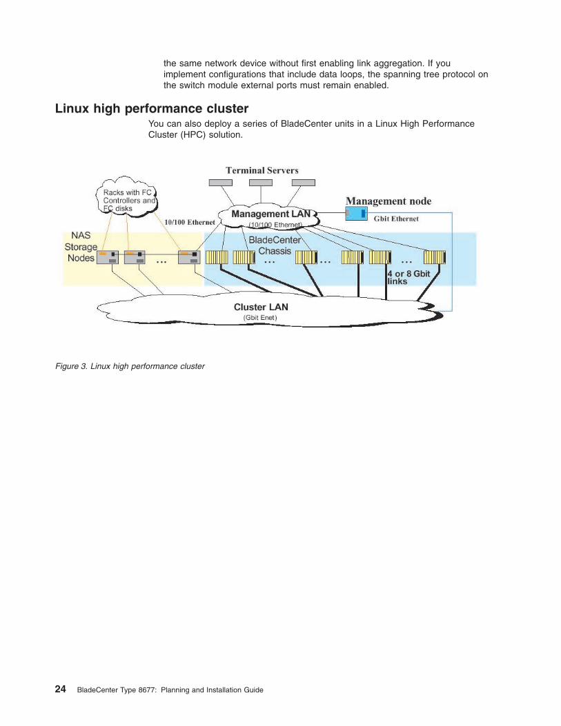
the
same
network
device
without
first
enabling
link
aggregation.
If
you
implement
configurations
that
include
data
loops,
the
spanning
tree
protocol
on
the
switch
module
external
ports
must
remain
enabled.
Linux
high
performance
cluster
You
can
also
deploy
a
series
of
BladeCenter
units
in
a
Linux
High
Performance
Cluster
(HPC)
solution.
Figure
3.
Linux
high
performance
cluster
24
BladeCenter
Type
8677:
Planning
and
Installation
Guide

Cluster
VLAN
This
example
shows
four
racks
containing
BladeCenter
units
implemented
in
a
cluster
VLAN.
Devices
in
each
rack
can
communicate
directly
with
devices
in
another
rack
through
the
Ethernet
Gb
switches
in
each
rack.
This
solution
can
support
up
to
210
processor
nodes.
It
could
also
be
expanded
through
the
use
of
an
additional
level
of
switches.
Figure
4.
Cluster
VLAN
Chapter
3.
Deployment
considerations
25
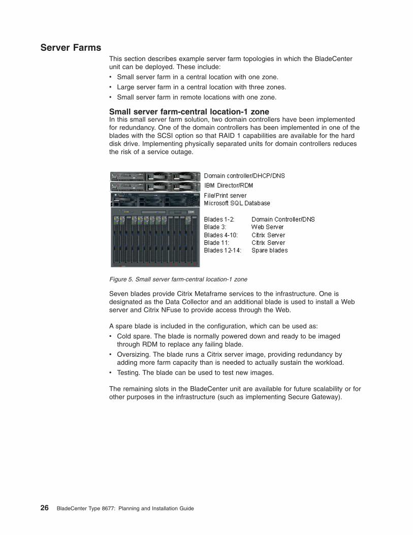
Server
Farms
This
section
describes
example
server
farm
topologies
in
which
the
BladeCenter
unit
can
be
deployed.
These
include:
v
Small
server
farm
in
a
central
location
with
one
zone.
v
Large
server
farm
in
a
central
location
with
three
zones.
v
Small
server
farm
in
remote
locations
with
one
zone.
Small
server
farm-central
location-1
zone
In
this
small
server
farm
solution,
two
domain
controllers
have
been
implemented
for
redundancy.
One
of
the
domain
controllers
has
been
implemented
in
one
of
the
blades
with
the
SCSI
option
so
that
RAID
1
capabilities
are
available
for
the
hard
disk
drive.
Implementing
physically
separated
units
for
domain
controllers
reduces
the
risk
of
a
service
outage.
Seven
blades
provide
Citrix
Metaframe
services
to
the
infrastructure.
One
is
designated
as
the
Data
Collector
and
an
additional
blade
is
used
to
install
a
Web
server
and
Citrix
NFuse
to
provide
access
through
the
Web.
A
spare
blade
is
included
in
the
configuration,
which
can
be
used
as:
v
Cold
spare.
The
blade
is
normally
powered
down
and
ready
to
be
imaged
through
RDM
to
replace
any
failing
blade.
v
Oversizing.
The
blade
runs
a
Citrix
server
image,
providing
redundancy
by
adding
more
farm
capacity
than
is
needed
to
actually
sustain
the
workload.
v
Testing.
The
blade
can
be
used
to
test
new
images.
The
remaining
slots
in
the
BladeCenter
unit
are
available
for
future
scalability
or
for
other
purposes
in
the
infrastructure
(such
as
implementing
Secure
Gateway).
Figure
5.
Small
server
farm-central
location-1
zone
26
BladeCenter
Type
8677:
Planning
and
Installation
Guide

Large
server
farm-central
location-3
zones
In
this
example,
three
zone
are
used
to
support
more
than
100
servers
in
a
single
location.
One
domain
controller
per
zone
has
been
deployed.
In
zone
1,
two
clustered
file/print
servers
relying
on
external
Fibre
Channel
storage
solutions
(not
pictured)
have
been
installed
to
support
all
of
the
users.
One
IBM
Director/RDM
server
is
included.
Figure
6.
Large
server
farm-central
location-3
zones
Chapter
3.
Deployment
considerations
27

Small
server
farm-remote
locations-1
zone
This
example
shows
the
configuration
for
a
small
server
farm
with
remote
sites.
The
BladeCenter
unit
is
used
to
concentrate
the
entire
LAN
infrastructure
in
a
small
7U
form
factor.
Each
remote
location
has
a
domain
controller,
server,
and
RDM
server,
which
is
dedicated
to
hosting
only
operating
system
images.
The
RDM
server
communicates
with
the
main
RDM
server
in
a
central
location
through
standard
HTTP
commands.
Each
site
has
spare
capacity.
In
the
central
location,
this
spare
capacity
can
be
used
for
development
or
testing
tasks.
Figure
7.
Small
server
farm-central
location-1
zone
28
BladeCenter
Type
8677:
Planning
and
Installation
Guide
Preparing
for
BladeCenter
deployment
To
configure
your
BladeCenter
unit,
you
need
to:
v
Determine
which
deployment
tools
you
are
going
to
use
v
Set
up
your
deployment
infrastructure
v
Configure
your
BladeCenter
unit:
–
Configure
the
management
module
–
Set
the
chassis
policies
–
Configure
the
switch
modules
This
section
provides
information
about
the
available
deployment
tools
and
setting
up
your
deployment
infrastructure.
Deployment
tools
Before
you
can
begin
using
the
BladeCenter
unit,
you
must
configure
each
of
the
components
(management
modules,
switch
modules,
and
blade
servers).
You
have
a
variety
of
options
available
to
configure
these
components.
For
example,
you
can
access
the
firmware
that
is
embedded
into
each
of
the
components
to
configure
the
component
using
either
of
these
options:
v
Through
a
Web
browser.
To
access
the
components
through
a
Web
browser,
point
the
browser
to
the
IP
address
for
the
component.
The
Web
browser
you
use
must
meet
the
following
requirements:
–
Support
for
Java™
–
Support
for
JavaScript™
1.2
–
Minimum
screen
resolution
of
800x600
with
256
colors.
If
you
point
to
the
management
module,
you
will
see
the
System
Status
menu
after
logging
in.
From
this
menu,
you
can
perform
management
module
configuration,
switch
module
configuration,
and
blade
server
configuration.
In
addition,
you
can
point
your
browser
to
the
IP
address
of
the
switch
modules
or
the
blade
server
to
configure
those
components
directly.
v
Through
a
Telnet
interface.
The
Telnet
interface
provides
a
command
line
interface
through
the
Management
module,
external
Ethernet
connection
(out
of
band),
or
external
Fibre
Channel
connection
(in
band).
The
command-line
interface
includes
a
Help
menu,
port
display
and
configuration,
general
switch
status
and
configuration,
and
Fibre
Channel
zoning
capability.
Instructions
for
using
the
Web
browser
interface
and
Telnet
are
provided
in
the
BladeCenter
Type
8677
Installation
and
User’s
Guide.
You
can
also
configure
BladeCenter
unit
components
using
these
deployment
tools:
v
IBM
Director
4.0.
You
can
use
IBM
Director
4.0,
which
includes
a
configuration
wizard
to
guide
you
step-by-step
through
the
various
configuration
options
that
are
available.
In
addition,
IBM
Director
4.0
enables
you
to
constantly
monitor
systems
and
handle
alerts
that
occur
in
the
case
of
hardware
or
software
outages.
For
additional
information
about
using
IBM
Director
with
the
deployment
of
your
BladeCenter
unit,
refer
to
IBM
Eserver
BladeCenter
Systems
Management,
which
is
available
at
http://www.ibm.com/redbooks.
v
Remote
Deployment
Manager
3.1.01
(must
include
Patch
2
or
above).
RDM
provides
an
easy-to-use
interface
that
allows
you
to
quickly
load
your
Windows
operating
system
images
on
one
or
more
blade
servers.
For
additional
information
about
using
RDM
with
the
deployment
of
your
BladeCenter
unit,
refer
Chapter
3.
Deployment
considerations
29
to
The
Cutting
Edge:
IBM
Eserver
BladeCenter
and
IBM
Eserver
BladeCenter
Systems
Management,
which
are
available
at
http://www.ibm.com/redbooks.
v
IBM
Cluster
Systems
Management
for
Linux®.
CSM
allows
you
to
perform
Linux
installations
over
a
network.
An
IBM
licensed
program,
CSM
provides
a
distributed
systems
management
solution
for
nodes
of
a
cluster
running
Red
Hat
7.1
(as
distributed
and
supported
by
Red
Hat).
More
information
about
using
CSM
is
available
at
the
following
Web
site:
http://www.ibm.com/servers/eserver/clusters/software/.
IBM
Director
4.0
and
RDM
3.1.01
provide
an
easy
way
to
configure
the
components
of
the
BladeCenter
unit
and
allows
you
to
quickly
reconfigure
your
servers
to
meet
workload
and
hardware
availability
requirements.
Instructions
for
using
IBM
Director
4.0
and
RDM
3.1.01
are
provided
in
the
BladeCenter
Type
8677
Installation
and
User’s
Guide.
Deployment
infrastructure
Although
the
deployment
of
the
BladeCenter
unit
does
not
require
you
to
do
so,
you
should
consider
setting
up
a
separate
management
network
to
configure
and
manage
your
BladeCenter
unit.
By
separating
the
LAN
segment
used
for
production
from
the
LAN
segment
to
which
the
BladeCenter
management
module
(as
well
as
the
IBM
Director
and
RDM
server,
if
present)
is
connected,
you
can
ensure
that
unauthorized
connections
are
not
possible.
Only
the
administrators’
systems
would
be
connected
to
this
LAN
segment.
You
should
also
consider
the
use
of
a
DHCP
server
to
lease
IP
addresses
on
the
management
LAN.
When
powered
on,
the
management
module
by
default
searches
for
a
DHCP
server
and
sets
a
default
static
IP
address
if
a
DHCP
server
is
not
found.
Because
the
default
static
IP
address
is
the
same
for
all
management
modules,
IP
address
conflicts
can
result
if
you
do
not
use
a
DHCP
server.
Figure
8
on
page
31
shows
an
example
network
that
might
be
used
to
configure
and
manage
your
BladeCenter.
30
BladeCenter
Type
8677:
Planning
and
Installation
Guide

Setting
up
the
management
connection
You
can
set
up
a
remote
management
connection
by
connecting
the
Ethernet
port
of
the
management
module
to
a
10/100
Mbps
network
with
access
to
a
management
station
or
you
can
connect
directly
to
a
management
station
from
the
Ethernet
port
of
the
management
module.
Complete
the
following
steps
to
connect
the
Ethernet
cable
to
the
management
module:
1.
Connect
one
end
of
a
Category
3,
4,
5
or
higher
Ethernet
cable
to
the
Ethernet
port
on
the
management
module.
Connect
the
other
end
of
the
Ethernet
cable
to
the
network.
Figure
8.
Management
network
diagram
Chapter
3.
Deployment
considerations
31

2.
Check
the
Ethernet
LEDs
to
ensure
that
the
network
connection
is
working.
The
following
illustration
shows
the
locations
of
the
Ethernet
LEDs.
OK
TX/RX
LINK
Ethernet link
Ethernet activity
Ethernet
link
LED
When
this
green
LED
is
lit,
there
is
an
active
connection
through
the
port.
Ethernet
activity
LED
When
this
green
LED
is
flashing,
it
indicates
that
there
is
activity
through
the
port.
After
you
connect
the
management
module
to
the
network,
the
Ethernet
port
connection
is
configured
and
enabled
in
one
of
the
following
ways:
v
If
you
have
an
accessible,
active,
and
configured
dynamic
host
configuration
protocol
(DHCP)
server
on
the
network,
the
host
name,
IP
address,
gateway
address,
subnet
mask,
and
DNS
server
IP
address
are
set
automatically.
v
If
the
DHCP
server
does
not
respond
within
two
minutes
after
the
port
is
connected,
the
management
module
uses
the
static
IP
address
and
subnet
address.
If
you
do
not
want
to
use
the
default
static
values,
you
can
configure
the
static
IP
address,
host
name,
and
subnet
mask
for
the
management
module
through
the
Web
interface.
The
default
IP
address
is
192.168.70.125,
the
default
subnet
address
is
255.255.255.0,
and
the
default
hostname
is
MMxxxxxxxxxxxx,
where
xxxxxxxxxxxx
is
the
burned-in
medium
access
control
(MAC)
address.
The
MAC
32
BladeCenter
Type
8677:
Planning
and
Installation
Guide

address
is
on
a
label
on
the
management
module,
below
the
IP
reset
button.
OK
TX/RX
LINK
MAC address
Note:
If
the
IP
configuration
is
assigned
by
the
DHCP
server,
the
network
administrator
can
use
the
MAC
address
of
the
management
module
network
interface
to
find
out
what
IP
address
and
host
name
are
assigned.
If
you
do
not
want
to
use
DHCP,
configure
the
static
IP
address,
then
disable
the
DHCP
client.
Deployment
Examples
This
section
describes
the
example
procedures
for
deploying
and
configuring
your
BladeCenter
unit:
v
Using
IBM
Director
and
a
DHCP
server
v
Using
IBM
Director
without
a
DHCP
server
v
Using
the
Web-based
interface
IBM
Director
and
DHCP
This
scenario
uses
the
following
assumptions:
v
The
IBM
Director
server
and
console
are
on
the
same
subnet
as
the
external
(management)
port
of
the
management
module.
v
A
DHCP
server
exists
on
the
same
subnet
as
well.
v
You
have
already
obtained
the
IP
addresses
on
the
same
subnet
for:
–
The
management
module
–
Each
switch
module
–
Each
processor
blade
(blade
server)
v
You
have
obtained
a
gateway
IP
address
and
subnet
mask
(if
needed).
Follow
this
steps
to
deploy
and
configure
your
BladeCenter
unit
using
IBM
Director
and
a
DHCP
server:
1.
Plug
in
the
BladeServer
and
check
the
LED
status.
2.
From
IBM
Director,
set
Chassis
Association
and
select
the
Chassis
&
Chassis
Members
group
view.
3.
Initiate
chassis
discovery.
The
BladeCenter
managed
object
appears
on
the
IBM
Director
console.
Chapter
3.
Deployment
considerations
33

4.
Right-click
the
BladeCenter
managed
object
and
select
Request
access.
5.
Enter
a
valid
user
ID
and
password
for
the
management
module.
The
default
user
ID
is
USERID
and
the
default
password
is
PASSW0RD
(numeric
0
and
not
uppercase
O).
6.
The
BladeCenter
managed
object
and
the
associated
processor
blades
appear
on
the
IBM
Director
console.
7.
Verify
that
the
processor
blade
object
matches
the
actual
blade.
Note:
Turn
on
the
BladeCenter
BlueLight
to
identify
the
BladeCenter
unit
you
are
managing.
8.
Configure
the
BladeCenter
management
module.
Select
the
MPA
ServerBlade
management
task
and
drag-and-drop
the
task
on
the
BladeCenter
managed
object.
9.
Configure
the
management
module.
a.
Enter
a
static
IP
address
for
NIC
1
if
desired.
b.
Enter
a
static
IP
address
for
NIC
2
(in
same
subnet
as
NIC
1).
When
prompted
to
reboot
the
management
module,
click
Yes.
10.
After
the
management
module
has
rebooted,
complete
the
configuration
of
the
management
module.
Note:
Changes
you
make
during
configuration,
such
as
changing
the
management
module
name,
will
not
automatically
appear
on
the
IBM
Director
console.
11.
Change
the
user
ID
and
password
for
the
management
module.
12.
Set
the
BladeCenter
policies.
Because
you
are
managing
the
BladeCenter
unit
from
IBM
Director,
you
should
disable
local
power
control,
local
keyboard/video/mouse
(KVM)
switching,
and
local
USB
media
switching.
13.
Configure
each
switch
module,
which
you
can
perform
from
the
ServerBlade
Management
task.
a.
Set
the
IP
address,
subnet
mask,
and
hostname
(if
applicable).
Note:
You
must
make
sure
that
the
IP
address
used
for
the
switch
is
on
the
same
subnet
as
the
external
IP
address
for
the
management
module
if
you
intend
to
manage
the
switch
through
the
management
module.
b.
Click
the
button
to
launch
a
Web
browser
to
start
the
embedded
switch
configuration
task.
You
must
have
IP
connectivity
between
the
console
and
the
switch.
c.
Make
sure
you
enable
SNMP
trap
forwarding
to
the
IP
address
of
the
IBM
Director
server.
IBM
Director
without
DHCP
This
scenario
uses
the
following
assumptions:
v
The
IBM
Director
server
and
console
are
on
the
same
subnet
as
the
external
(management)
port
of
the
management
module.
You
could
also
connect
directly
to
the
external
port
on
the
management
module
using
a
laptop
or
server
that
has
IBM
Director
installed.
If
you
connect
directly,
the
IP
address
of
the
laptop
or
server
must
be
on
the
same
subnet
as
the
static
IP
address
of
the
management
module.
v
You
have
already
obtained
the
IP
addresses
on
the
same
subnet
for:
–
The
management
module
34
BladeCenter
Type
8677:
Planning
and
Installation
Guide

–
Each
switch
module
–
Each
processor
blade
(blade
server)
v
You
have
obtained
a
gateway
IP
address
and
subnet
mask
(if
needed).
Follow
these
steps
to
deploy
and
configure
your
BladeCenter
unit
using
IBM
Director
(but
without
a
DHCP
server):
1.
Plug
in
the
Blade
Server
and
check
the
LED
status.
2.
From
IBM
Director,
set
Chassis
Association
and
select
the
Chassis
&
Chassis
Members
group
view.
3.
Initiate
chassis
discovery.
The
BladeCenter
managed
object
appears
on
the
IBM
Director
console.
4.
Right-click
the
BladeCenter
managed
object
and
select
Request
access.
5.
Enter
a
valid
user
ID
and
password
for
the
management
module.
The
default
user
ID
is
USERID
and
the
default
password
is
PASSW0RD
(numeric
0
and
not
uppercase
O).
6.
The
BladeCenter
managed
object
and
the
associated
processor
blades
appear
on
the
IBM
Director
console.
7.
Verify
that
the
processor
blade
object
matches
the
actual
blade.
Note:
Turn
on
the
BladeCenter
BlueLight
to
identify
the
BladeCenter
unit
you
are
managing.
8.
Configure
the
BladeCenter
management
module.
Select
the
MPA
ServerBlade
management
task
and
drag-and-drop
the
task
on
the
BladeCenter
managed
object.
9.
Configure
the
management
module.
a.
Enter
a
static
IP
address
for
NIC
1
if
desired.
b.
Enter
a
static
IP
address
for
NIC
2
(in
same
subnet
as
NIC
1).
When
prompted
to
reboot
the
management
module,
click
Yes.
10.
After
the
management
module
has
rebooted,
complete
the
configuration
of
the
management
module.
Note:
Changes
you
make
during
configuration,
such
as
changing
the
management
module
name,
will
not
automatically
appear
on
the
IBM
Director
console.
11.
Change
the
user
ID
and
password
for
the
management
module.
12.
Set
the
BladeCenter
policies.
Because
you
are
managing
the
BladeCenter
from
IBM
Director,
you
should
disable
local
power
control,
local
keyboard/video/mouse
(KVM)
switching,
and
local
USB
media
switching.
13.
Configure
each
switch
in
the
chassis,
which
you
can
perform
from
the
ServerBlade
Management
task.
a.
Set
the
IP
address,
subnet
mask,
and
hostname
(if
applicable).
Note:
You
must
make
sure
that
the
IP
address
used
for
the
switch
is
on
the
same
subnet
as
the
external
IP
address
for
the
management
module
if
you
intend
to
manage
the
switch
through
the
management
module.
b.
Click
the
button
to
launch
a
Web
browser
to
start
the
embedded
switch
configuration
task.
You
must
have
IP
connectivity
between
the
console
and
the
switch.
c.
Make
sure
you
enable
SNMP
trap
forwarding
to
the
IP
address
of
the
IBM
Director
server.
Chapter
3.
Deployment
considerations
35

Web-based
interface
This
scenario
uses
the
following
assumptions:
v
A
Web
browser
is
installed
on
a
server
that
is
on
the
same
subnet
as
the
external
(management)
port
of
the
management
module.
You
could
also
connect
directly
to
the
external
port
on
the
management
module
using
a
laptop
or
server.
If
you
connect
directly,
the
IP
address
of
the
laptop
or
server
must
be
on
the
same
subnet
as
the
static
IP
address
of
the
management
module.
v
You
have
already
obtained
the
IP
addresses
on
the
same
subnet
for:
–
The
management
module
–
Each
switch
module
–
Each
processor
blade
(blade
server)
v
You
have
obtained
a
gateway
IP
address
and
subnet
mask
(if
needed).
Follow
these
steps
to
deploy
and
configure
your
BladeCenter
unit
using
the
Web-based
interface:
1.
Plug
in
the
blade
server
and
check
the
LED
status.
2.
Open
your
browser
and
point
to
the
external
IP
address
of
the
management
module.
3.
Enter
a
valid
user
ID
and
password
for
the
management
module.
The
default
user
ID
is
USERID
and
the
default
password
is
PASSW0RD
(numeric
0
and
not
uppercase
O).
4.
Verify
the
number
of
processor
blades,
switch
modules,
power
modules,
and
fans
against
the
actual
chassis
components.
Note:
Turn
on
the
BladeCenter
BlueLight
to
identify
the
BladeCenter
unit
you
are
managing.
5.
Configure
the
management
module.
Selecting
the
appropriate
links
from
the
Web-based
interface.
a.
Enter
a
static
IP
address
for
NIC
1
if
desired.
b.
Enter
a
static
IP
address
for
NIC
2
(in
same
subnet
as
NIC
1).
When
prompted
to
reboot
the
management
module,
click
Yes.
6.
After
the
Management
Module
has
rebooted,
log
back
into
the
interface
to
continue
configuration.
7.
Change
the
user
ID
and
password
for
the
management
module.
8.
Configure
each
switch
in
the
BladeCenter
unit
by
setting
the
IP
address,
subnet
mask,
and
hostname
(if
applicable).
Preparing
for
Blade
Server
deployment
This
section
describes
the
considerations
for
deploying
a
blade
server.
Hardware
considerations
You
can
choose
to
add
the
following
hardware
options
to
a
blade
server:
v
Up
to
two
microprocessors.
With
two
microprocessors,
your
blade
server
can
operate
as
a
symmetric
multiprocessing
(SMP)
server.
To
ensure
proper
server
operation
when
you
install
an
additional
microprocessor,
use
microprocessors
that
have
the
same
cache
size
and
type,
and
the
same
clock
speed.
Internal
and
external
clock
frequencies
must
be
identical.
v
Up
to
two
optional
2.5-inch
IDE
hard
disk
drives.
36
BladeCenter
Type
8677:
Planning
and
Installation
Guide

v
Memory-module
options
to
increase
the
amount
of
memory
in
your
blade
server.
When
you
install
memory,
you
must
install
a
pair
of
matched
dual
inline
memory
modules
(DIMMs).
v
A
Fibre
Channel
I/O
expansion
option,
which
will
provide
the
blade
server
with
two
additional
network
connections
for
communicating
on
a
network.
If
you
add
a
Fibre
Channel
I/O
expansion
option,
you
must
make
sure
the
switch
module
in
switch
module
bays
3
and
4
on
the
BladeCenter
unit
use
the
Fibre
Channel
interface.
In
addition,
the
I/O
expansion
option
occupies
the
same
location
on
the
blade
server
as
the
second
2.5-inch
IDE
hard
drive
drive.
Therefore,
you
can
install
only
one
2.5-inch
IDE
hard
disk
drive.
v
SCSI
storage
expansion
unit
to
use
SCSI
hard
disk
drives
with
your
blade
server.
With
the
SCSI
storage
expansion
unit,
you
can
install
up
to
two
1-inch
(26
mm)
slim-high,
3.5-inch,
hot-swap
SCSI
hard
disk
drives.
If
you
install
the
SCSI
storage
expansion
unit,
the
blade
server
will
occupy
two
blade
bays
in
the
BladeCenter
unit.
Firmware
considerations
You
can
download
the
latest
firmware
for
a
blade
server
at
http://www.ibm.com/pc/support/.
After
downloading
the
latest
firmware,
use
the
BladeCenter
management
module
Web
interface
to
flash
the
system-management
module.
The
Web
interface
is
described
in
the
IBM
BladeCenter
Installation
and
User’s
Guide
on
the
IBM
BladeCenter
Documentation
CD.
BIOS
When
the
BIOS
code
page
jumper
(J12)
is
moved
from
pins
1
and
2
(the
default
position)
to
pins
2
and
3
on
the
blade
server
system
board,
you
can
boot
the
blade
server
from
a
backup
BIOS
page.
See
the
blade
server
Hardware
Maintenance
Manual
and
Troubleshooting
Guide
on
the
IBM
BladeCenter
Documentation
CD
for
complete
details.
Note:
If
you
boot
from
the
backup
page
because
the
primary
BIOS
page
has
become
damaged,
you
need
to
re-flash
the
primary
BIOS
code.
Operating
system
considerations
The
following
operating
systems
are
supported
on
a
blade
server:
v
Microsoft
Windows
2000
Server
v
Microsoft
Windows
2000
Advanced
Server
v
Red
Hat
Linux
7.3
v
SuSE
Professional
8.0
Windows
2000
installation
considerations
Information
about
installing
Windows
2000
and
Windows
XP
on
a
blade
server
is
on
the
IBM
Support
Web
page
at
http://www.ibm.com/pc/support/.
From
the
IBM
Support
Web
page
select
Servers;
then,
select
OS
installation
and
choose
the
operating
system
to
install
from
the
Operating
system
installation
by
category
drop-down
list.
In
addition,
you
can
find
redpieces
and
redpapers
about
installing
Windows
2000
on
the
BladeCenter
unit
at
http://www.ibm.com/redbooks
(search
for
BladeCenter).
Note
the
following
considerations
when
installing
Windows
2000
Server
or
Windows
2000
Advanced
Server
on
a
blade
server:
Chapter
3.
Deployment
considerations
37
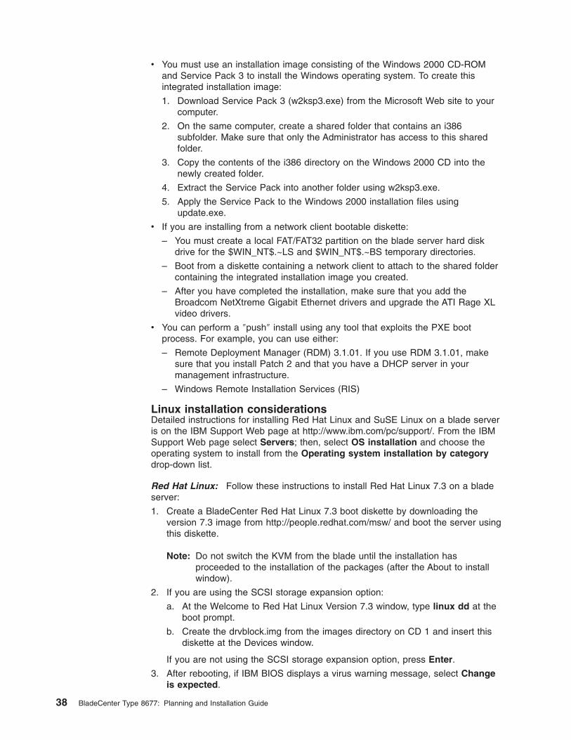
v
You
must
use
an
installation
image
consisting
of
the
Windows
2000
CD-ROM
and
Service
Pack
3
to
install
the
Windows
operating
system.
To
create
this
integrated
installation
image:
1.
Download
Service
Pack
3
(w2ksp3.exe)
from
the
Microsoft
Web
site
to
your
computer.
2.
On
the
same
computer,
create
a
shared
folder
that
contains
an
i386
subfolder.
Make
sure
that
only
the
Administrator
has
access
to
this
shared
folder.
3.
Copy
the
contents
of
the
i386
directory
on
the
Windows
2000
CD
into
the
newly
created
folder.
4.
Extract
the
Service
Pack
into
another
folder
using
w2ksp3.exe.
5.
Apply
the
Service
Pack
to
the
Windows
2000
installation
files
using
update.exe.
v
If
you
are
installing
from
a
network
client
bootable
diskette:
–
You
must
create
a
local
FAT/FAT32
partition
on
the
blade
server
hard
disk
drive
for
the
$WIN_NT$.~LS
and
$WIN_NT$.~BS
temporary
directories.
–
Boot
from
a
diskette
containing
a
network
client
to
attach
to
the
shared
folder
containing
the
integrated
installation
image
you
created.
–
After
you
have
completed
the
installation,
make
sure
that
you
add
the
Broadcom
NetXtreme
Gigabit
Ethernet
drivers
and
upgrade
the
ATI
Rage
XL
video
drivers.
v
You
can
perform
a
″push″
install
using
any
tool
that
exploits
the
PXE
boot
process.
For
example,
you
can
use
either:
–
Remote
Deployment
Manager
(RDM)
3.1.01.
If
you
use
RDM
3.1.01,
make
sure
that
you
install
Patch
2
and
that
you
have
a
DHCP
server
in
your
management
infrastructure.
–
Windows
Remote
Installation
Services
(RIS)
Linux
installation
considerations
Detailed
instructions
for
installing
Red
Hat
Linux
and
SuSE
Linux
on
a
blade
server
is
on
the
IBM
Support
Web
page
at
http://www.ibm.com/pc/support/.
From
the
IBM
Support
Web
page
select
Servers;
then,
select
OS
installation
and
choose
the
operating
system
to
install
from
the
Operating
system
installation
by
category
drop-down
list.
Red
Hat
Linux:
Follow
these
instructions
to
install
Red
Hat
Linux
7.3
on
a
blade
server:
1.
Create
a
BladeCenter
Red
Hat
Linux
7.3
boot
diskette
by
downloading
the
version
7.3
image
from
http://people.redhat.com/msw/
and
boot
the
server
using
this
diskette.
Note:
Do
not
switch
the
KVM
from
the
blade
until
the
installation
has
proceeded
to
the
installation
of
the
packages
(after
the
About
to
install
window).
2.
If
you
are
using
the
SCSI
storage
expansion
option:
a.
At
the
Welcome
to
Red
Hat
Linux
Version
7.3
window,
type
linux
dd
at
the
boot
prompt.
b.
Create
the
drvblock.img
from
the
images
directory
on
CD
1
and
insert
this
diskette
at
the
Devices
window.
If
you
are
not
using
the
SCSI
storage
expansion
option,
press
Enter.
3.
After
rebooting,
if
IBM
BIOS
displays
a
virus
warning
message,
select
Change
is
expected.
38
BladeCenter
Type
8677:
Planning
and
Installation
Guide

4.
Log
in
as
root
and
install
the
2.4.18–18.7.x
or
later
kernel
errata
using
RPM
Package
Manager.
5.
Create
an
entry
for
the
floppy
drive
in
the
/etc/fstab
file.
Note:
The
floppy
resides
on
the
SCSI
device
after
all
other
devices.
6.
Make
a
directory
for
the
floppy
under
/mnt
7.
Mount
the
floppy.
8.
If
you
are
using
the
GNOME
desktop,
remove
the
magicdev
package
(to
avoid
a
system
hang).
The
ability
of
the
remote
console
applet
to
accurately
track
the
location
of
the
mouse
cursor
in
a
Linux
X
Window
System
session
depends
on
the
configuration
of
X
Windows.
Therefore,
you
must
set
the
mouse
handler
with
the
correct
resolution
information
to
track
the
remote
mouse
cursor
properly.
In
addition,
set
the
mouse
acceleration
and
threshold
values
to
1
to
synchronize
the
remote
and
local
mouse.
SuSE
8.0:
Consider
the
following
when
installing
SuSE
on
a
blade
server:
v
When
you
start
the
server
and
insert
the
SuSE
Linux
Version
8.0
CD
1
into
the
CD-ROM
drive,
the
CD
may
not
start.
In
this
case,
use
the
SuSE
Linux
Version
8.0
CD
2
to
start.
v
You
may
encounter
problems
with
mouse
synchronization
if
you
are
installing
remotely
using
the
remote
control
option
of
the
BladeCenter
management
module.
These
problems
can
be
resolved
after
installation.
During
installation,
you
may
have
to
double-click
to
make
selections
that
normally
only
require
a
single
click.
v
When
the
installer
starts,
the
mouse
will
not
work.
To
resolve
the
problem,
when
the
installer
starts,
use
keyboard
navigation
to
ensure
that
the
mouse
is
listed
as
a
USB
mouse.
Device
driver
considerations
Some
of
the
options
available
for
the
BladeCenter
unit
have
device
drivers
that
you
need
to
install.
See
the
documentation
that
comes
with
your
option
for
information
about
installing
any
required
device
drivers.
For
example,
Ethernet
controllers
are
integrated
on
each
blade
server
system
board.
The
Ethernet
controllers
provide
1000-Mbps
full-duplex
capability
only,
which
enables
simultaneous
transmission
and
reception
of
data
to
the
external
ports
on
the
Ethernet
switches.
You
do
not
need
to
set
any
jumpers
or
configure
the
controller
for
the
blade
server
operating
system.
However,
you
must
install
a
device
driver
in
the
blade
server
to
enable
the
blade
server
operating
system
to
address
the
Ethernet
controller.
For
blade
server
device
driver
and
information
about
configuring
the
Ethernet
controllers,
see
the
Broadcom
NetXtreme
Ethernet
Software
CD
that
comes
with
the
BladeCenter
unit.
Chapter
3.
Deployment
considerations
39

Application
considerations
Information
about
some
of
the
applications
including
system
management
are
provided
in
these
redpieces
and
redpapers
available
at
http://www.ibm.com/redbooks:
v
Deploying
Lotus
Domino
on
IBM
Eserver
BladeCenter
v
Deploying
Citrix
MetalFrame
on
IBM
Eserver
BladeCenter
v
Deploying
Microsoft
Exchange
IBM
Eserver
BladeCenter
v
The
Cutting
Edge:
IBM
Eserver
BladeCenter
40
BladeCenter
Type
8677:
Planning
and
Installation
Guide

Chapter
4.
Installation
considerations
This
chapter
describes
the
installation
site
physical
requirements
that
must
be
in
place
to
be
able
to
complete
the
installation
of
a
BladeCenter
unit.
The
following
topics
are
discussed:
v
“Physical
planning”
describes
chassis
dimensions,
weight,
floor
space,
and
noise
considerations.
v
“Rack
considerations”
on
page
43
describes
weight
and
space
limits
of
IBM
NetBAY
racks.
v
“Power
considerations”
on
page
45
describes
rack
and
BladeCenter
unit
power
requirements
v
“Cooling
considerations”
on
page
50
describes
temperature
and
humidity,
air
flow,
room
cooling,
and
heat
output.
v
“Power
connections”
on
page
51
provides
sample
diagrams
for
power
and
cabling.
v
“Physical
installation
time”
on
page
72
shows
approximate
times
for
installing
BladeCenter
units,
blade
servers,
and
other
components.
For
access
to
configuration
tools
and
additional
information,
(such
as
the
Rack
Configurator
and
the
Configuration
Options
Guide),
go
to
this
site:
http://www.pc.ibm.com/us/eserver/xseries/library/configtools
Physical
planning
This
section
describes
dimensions,
weight,
floor
space,
and
noise
considerations.
Dimensions
A
BladeCenter
unit
has
the
following
dimensions:
Width
444
mm
(17.5
in.)
Height
304.2
mm
(12
in.)
Depth
711.2
mm
(28
in.)
A
BladeCenter
unit
uses
7U
of
vertical
rack
space.
The
following
clearances
are
required
inside
the
rack:
50
mm
(1.96
in.)
on
each
side
of
the
chassis
100
mm
(3.93
in.)
at
the
back
of
the
chassis
for
cables.
Weight
considerations
The
following
factors
are
important
when
planning
for
the
physical
installation
of
BladeCenter
units:
v
Racks
have
a
maximum
weight
load
limit.
v
Floors,
particularly
raised
floors
have
maximum
weight
limits.
Floor
space
Figure
9
on
page
42
shows
the
required
floor
space
for
an
IBM
NetBAY
rack.
This
diagram
shows
the
space
needed
to
allow
enough
clearance
in
the
front
and
rear
of
the
rack
to
be
able
to
open
the
doors
to
access
the
equipment.
Front
clearance
is
needed
to
have
access
to
the
blade
servers
and
the
BladeCenter
media
tray.
Rear
clearance
is
needed
to
access
power
supplies,
blowers,
network
cable
connections,
©
Copyright
IBM
Corp.
2003
41

and
attachment
of
a
local
monitor,
keyboard,
and
mouse
to
the
management
module.
Noise
considerations
Each
BladeCenter
unit
has
two
blowers
for
cooling.
An
optional
Acoustics
Module
is
available
that
dampens
the
noise
generated
by
the
blowers.
Table
3
shows
the
maximum
sound
levels
emitted
by
BladeCenter
units
without
the
Acoustics
Module
and
with
the
Acoustics
Module.
This
represents
the
minimum
and
maximum
number
of
BladeCenter
units
that
can
be
installed
in
a
42U
rack.
Table
3.
BladeCenter
noise
emissions
Number
of
BladeCenter
units
per
rack
Maximum
sound
power
idle
Maximum
sound
power
operating
Without
Acoustics
Module
1
7.4
bels
7.4
bels
With
Acoustics
Module
1
6.9
bels
6.9
bels
Without
Acoustics
Module
4
8
bels
8
bels
With
Acoustics
Module
4
7.5
bels
7.5
bels
Without
Acoustics
Module
6
8.2
bels
8.2
bels
With
Acoustics
Module
6
7.7
bels
7.7
bels
NetBayRack C
3438 mm135.35”
3850 mm151.57”
914 mm35.98”
1524 mm60.00”
NetBayRack B
NetBayRack A
Front
Figure
9.
Operational
clearances
for
NetBAY
42
Enterprise
rack
42
BladeCenter
Type
8677:
Planning
and
Installation
Guide

Attention:
Your
server
installation
may
be
subject
to
government
regulations,
such
as
those
prescribed
by
OSHA
or
European
Community
Directives,
that
cover
noise-level
exposure
in
the
workplace.
The
BladeCenter
unit
is
available
with
an
optional
acoustic
attenuation
module
that
can
reduce
the
likelihood
of
exceeding
noise-level
exposure
limits.
The
actual
sound-pressure
levels
in
your
installation
depends
on
a
variety
of
factors,
including
the
number
of
servers
in
the
installation,
the
size,
materials,
and
configuration
of
the
room
where
the
servers
are
installed,
the
noise
levels
from
other
equipment,
the
room
ambient
temperature,
and
employees’
location
in
relation
to
the
equipment.
It
is
recommended
that
a
qualified
person,
such
as
an
industrial
hygienist,
be
consulted
to
determine
whether
the
sound-pressure
levels
to
which
employees
may
be
exposed
exceed
regulatory
limits.
Rack
considerations
IBM
NetBAY
When
planning
for
IBM
NetBAY
racks
the
following
factors
must
be
considered:
v
floor
space
that
provides
adequate
access
to
the
front
and
rear
of
the
rack,
and
space
on
both
sides
of
the
rack
or
a
row
of
racks
for
ventilation
and
walk
through
space.
See
Figure
9
on
page
42.
v
rack
weight
load
limits
and
floor
weight
load
limits.
See
Table
4
on
page
44.
v
rack
height
–
each
BladeCenter
unit
requires
7U,
also
consider
the
space
needed
for
other
equipment
that
might
be
installed
in
the
same
rack
with
the
BladeCenter
units.
See
Table
4
on
page
44.
Table
4
on
page
44
shows
the
maximum
weight
limits
for
IBM
NetBAY
racks
and
expansion
cabinets
that
are
recommended
for
use
with
BladeCenter
units.
The
table
shows
the
maximum
number
of
BladeCenter
units
that
can
be
installed
in
a
NetBAY
rack
when
the
rack
is
either:
v
installed
in
placed
and
sitting
on
the
rack
leveling
pads
v
being
relocated
and
is
sitting
on
the
rack
casters.
v
is
being
shipped
on
a
pallet.
Chapter
4.
Installation
considerations
43

Note:
For
the
On
site
relocation,
rack
on
casters,
column
the
maximum
number
of
BladeCenter
units
(including
the
PDUs
to
support
the
configuration)
is
based
on
a
14–degree
stability
requirement
established
under
IBM
safety
guidelines.
Table
4.
IBM
NetBAY
rack
weight
load
limits
Rack
Rack
weight
Maximum
allowable
rack
weight
load
Maximum
fully
loaded
BladeCenter
units
with
rack
on
leveling
pads
On
site
relocation,
rack
on
casters,
maximum
number
of
BladeCenter
units
Shipping
on
pallet,
maximum
number
of
BladeCenter
units
NetBAY
42
Enterprise
Rack
261
kg
(575
lb)
932
kg
(2050
lb)
6
3
3
NetBAY
42
Enterprise
Expansion
Cabinet
235
kg
(516
lb)
932
kg
(2050
lb)
6
3
3
NetBAY
42
Standard
Rack
137
kg
(301
lb)
909
kg
(2000
lb)
6
3
0
NetBAY
42
Standard
Expansion
Cabinet
105
kg
(231
lb)
909
kg
(2000
lb)
6
3
0
NetBAY
25
Standard
Rack
94
kg
(207
lb)
568
kg
(1250
lb)
3
3
3
NetBAY
11
Standard
Rack
34
kg
(75
lb)
185
kg
(407
lb)
1
1
1
When
determining
your
floor
load
limits,
use
the
combined
weight
of
the
rack,
populated
BladeCenter
units,
power
distribution
units
and
other
rack
mounting
hardware
to
ensure
the
installation
site
can
safely
support
the
total
weight.
Consult
your
local
building
engineer
to
understand
the
weight
limits
at
your
site.
Worksheets
are
provided
in
Appendix
A,
“Planning
worksheets,”
on
page
85.
Moving
IBM
NetBAY
racks
safely
It
is
very
important
to
ensure
that
you
move
racks
safely.
For
42U
racks,
all
equipment
installed
above
22U
in
the
rack
must
be
removed
before
a
rack
can
be
moved
to
another
location.
Before
moving
a
rack,
be
sure
to
carefully
read
the
instructions
that
are
provided
with
your
rack.
Using
non-IBM
racks
If
you
intend
to
install
BladeCenter
units
in
a
rack
other
than
an
IBM
NetBAY
rack,
verify
that
the
rack
meets
these
requirements:
v
The
rack
mounting
flanges
has
holes
and
clearances
per
EIA-310-D
v
Rack
with
a
front
to
rear
spacing
of
698.50
mm
(27.5
in)
to
723.90
mm
(28.5
in)
44
BladeCenter
Type
8677:
Planning
and
Installation
Guide

v
Sufficient
room
in
front
of
the
front
EIA
flange
to
provide
bezel
clearance.
EIA-310-D
requires
this
space
to
be
a
minimum
of
49
mm
deep
v
Sufficient
room
behind
the
rear
of
the
rear
EIA
flanges
to
provide
room
for
cable
management
arms
and
cable
routing.
v
Rack
should
provide
an
adequate
flow
of
cooling
air
and
prevent
recirculation
of
warm
air
from
the
rear
to
the
front.
v
Racks
must
have
perforated
front
and
rear
doors.
v
Rack
weight
handling
capacity
should
be
sufficient
for
the
aggregate
weight
of
the
BladeCenter
units,
blade
servers,
power
distribution
units
and
power
cables.
v
Racks
need
to
be
stabilized
so
that
the
rack
does
not
become
unstable
when
fully
loaded.
Power
considerations
BladeCenter
units
have
redundant
power
modules.
AC
power
resources
must
be
adequate
to
not
only
supply
the
required
voltage
and
amperage,
but
should
also
be
designed
to
take
advantage
of
the
power
redundancy
provided
by
the
BladeCenter
unit.
Table
5
shows
how
power
is
provided
to
the
BladeCenter
components.
Table
5.
BladeCenter
power
modules
Component
Power
module
bays
Blade
Server
Bays
1
through
6
Ethernet
Switch
Modules
Management
Modules
Media
Tray
Fibre
Channel
Switch
Modules
Blowers
1,
2
Blade
Server
Bays
7
through
14
3,
4
To
take
advantage
of
the
BladeCenter
power
redundancy,
power
modules
1
and
3
should
be
connected
to
different
AC
power
sources
than
power
modules
2
and
4
including:
v
Building
AC
power
sources
v
Front
end
PDUs
v
Rack
PDUs.
Rack
requirements
Depending
on
how
many
BladeCenter
units
are
installed
in
a
rack
and
the
total
number
of
power
modules,
two
to
sixteen
power
distribution
units
(PDUs)
are
required.
Power
distribution
units
(PDUs)
Each
BladeCenter
unit
has
a
minimum
of
2
or
a
maximum
of
4
power
modules.
When
planning
for
AC
rack
power
distribution
be
sure
to
plan
for
enough
individual
power
feeds
and
PDUs
to
take
advantage
of
the
redundant
BladeCenter
power
supplies.
Chapter
4.
Installation
considerations
45

Each
BladeCenter
unit
requires:
v
2
to
4
AC
power
cords,
1
per
power
module
v
Each
power
module
should
be
powered
from
separate
high
voltage
AC
resources.
v
200
to
240
Vac
50
or
60
Hz
Table
6,
Table
7,
Table
8
on
page
47,
and
Table
9
on
page
47show
the
part
numbers
and
the
number
of
power
distribution
units
required
to
provide
power
source
for
1
to
6
BladeCenter
units
in
a
rack.
Table
6.
PDUs
for
20
amp
feeds
Number
of
BladeCenter
units
With
1200
W
power
supplies
With
1400
W
power
supplies
With
1800W
power
supplies
1
2
PDUs
PN
32P1736
4
PDUs
PN
32P1736
Not
supported2
2
4
PDUs
PN
32P1736
8
PDUs
PN
32P1736
Not
supported2
3
6
PDUs
PN
32P1736
12
PDUs
PN
32P1736
Not
supported2
4
8
PDUs
PN
32P1736
16
PDUs
PN
32P17361
Not
supported2
5
10
PDUs
PN
32P1736
20
PDUs
PN
32P17361
Not
supported2
6
12
PDUs
PN
32P1736
Not
supported1
Not
supported2
Notes:
1.
A
maximum
of
12
PDUs
can
be
mounted
in
the
zero
U
space
of
the
42U
Standard
rack.
A
maximum
of
16
PDUs
can
be
mounted
in
the
zero
U
space
of
the
42U
Enterprise
rack.
2.
There
are
no
PDUs
available
that
support
the
plug
an
1800
W
power
supply
requires.
Table
7.
PDUs
for
30
amp
feeds
Number
of
BladeCenter
units
With
1200
W
power
supplies
With
1400
W
power
supplies
With
1800
W
power
supplies
1
2
PDUs
PN
32P1766
and
2
PDUs
PN
32P1736
2
PDUs
PN
32P1766
2
PDUs
PN
32P1766
2
4
PDUs
PN
32P1766
and
4
PDUs
PN
32P1736
4
PDUs
PN
32P1766
4
PDUs
PN
32P1766
3
4
PDUs
PN
32P1766
and
8
PDUs
PN
32P1736
6
PDUs
PN
32P1766
6
PDUs
PN
32P1766
4
6
PDUs
PN
32P1766
and
10
PDUs
PN
32P1736
8
PDUs
PN
32P1766
8
PDUs
PN
32P1766
46
BladeCenter
Type
8677:
Planning
and
Installation
Guide

Table
7.
PDUs
for
30
amp
feeds
(continued)
Number
of
BladeCenter
units
With
1200
W
power
supplies
With
1400
W
power
supplies
With
1800
W
power
supplies
5
Not
supported
(see
note
below)
10
PDUs
PN
32P1766
10
PDUs
PN
32P1766
6
Not
supported
(see
note
below)
12
PDUs
PN
32P1766
12
PDUs
PN
32P1766
Note:
A
maximum
of
12
PDUs
can
be
mounted
in
the
zero
U
space
of
the
42U
Standard
rack.
A
maximum
of
16
PDUs
can
be
mounted
in
the
zero
U
space
of
the
42U
Enterprise
rack.
Table
8.
PDUs
for
60
amp
feeds
Number
of
BladeCenter
units
With
1200
W
power
supplies
With
1400
W
power
supplies
With
1800
W
power
supplies
1
2
PDUs
PN
32P1767
and
2
PDUs
PN
32P1736
2
PDUs
PN
32P1767
or
2
PDUs
PN
73P5855
2
PDUs
PN
32P1767
or
2
PDUs
PN
73P5855
2
2
PDUs
PN
32P1767
and
4
PDUs
PN
32P1736
2
PDUs
PN
73P5855
2
PDUs
PN
73P5855
3
2
PDUs
PN
32P1767
and
6
PDUs
PN
32P1736
4
PDUs
PN
32P1767
or
4
PDUs
PN
73P5855
4
PDUs
PN
32P1767
or
4
PDUs
PN
73P5855
4
4
PDUs
PN
32P1767
and
8
PDUs
PN
32P1736
4
PDUs
PN
73P5855
4
PDUs
PN
73P5855
5
4
PDUs
PN
32P1767
and
10
PDUs
PN
32P1736
4
PDUs
PN
73P5855
8
PDUs
PN
32P1767
6
4
PDUs
PN
32P1767
and
12
PDUs
PN
32P1736
8
PDUs
PN
32P1767
8
PDUs
PN
32P1767
Table
9.
PDUs
for
60
amp
3-phase
AC
feeds
Number
of
BladeCenter
units
With
1200
W
power
supplies
With
1400
W
power
supplies
With
1800
W
power
supplies
1
Not
supported
(see
note
below)
2
PDUs
PN
73P5847
2
PDUs
PN
73P5847
2
Not
supported
(see
note
below)
2
PDUs
PN
73P5847
2
PDUs
PN
73P5847
Chapter
4.
Installation
considerations
47

Table
9.
PDUs
for
60
amp
3-phase
AC
feeds
(continued)
Number
of
BladeCenter
units
With
1200
W
power
supplies
With
1400
W
power
supplies
With
1800
W
power
supplies
3
Not
supported
(see
note
below)
2
PDUs
PN
73P5847
2
PDUs
PN
73P5847
4
Not
supported
(see
note
below)
2
PDUs
PN
73P5847
4
PDUs
PN
73P5847
5
Not
supported
(see
note
below)
4
PDUs
PN
73P5847
4
PDUs
PN
73P5847
6
Not
supported
(see
note
below)
4
PDUs
PN
73P5847
4
PDUs
PN
73P5847
Note:
1200
W
power
supplies
do
not
ship
with
the
required
cable
to
connect
to
a
60A
3-phase
feed.
For
recommended
ways
of
providing
power
sources
to
BladeCenter
racks
see
“Power
connections”
on
page
51.
This
section
provides
diagrams
that
show
different
ways
to
provide
redundant
power
sources
to
one
or
more
BladeCenter
units.
These
diagrams
are
based
on
using
IBM
NetBAY
Enterprise
racks.
Wall
and
floor
power
drop
requirements
Figure
10
through
Figure
14
on
page
49
shows
AC
power
connectors
that
can
be
used
for
attachment
of
power
feeds
to
the
rack
PDUs.
E
N P
15A
AS 3112
20A
L6-20
W G
Y
16A
SABS 164
E
L N
13A
BS 1363/A
E
L N
16A
CEI 23-16
16A
SI 32
P N
E
16A
IEC 309CEE7 VII
16A
E E
Figure
10.
Rack
PDU
—
20A
single
phase
30A
L6-30P
Y
GX
32A
IEC 309
Figure
11.
Rack
PDU
—
30A
and
32A
single
phase
48
BladeCenter
Type
8677:
Planning
and
Installation
Guide

Keyboard,
video,
and
mouse
The
management
module
provides
a
set
of
connectors
for
attaching
a
keyboard,
monitor,
and
mouse
to
the
BladeCenter
unit.
This
provides
a
method
for
performing
local
installation
tasks,
system
management
tasks,
and,
if
necessary,
problem
determination.
Either
plan
for
a
mobile
keyboard,
mouse,
and
monitor
that
can
be
attached
to
a
specific
BladeCenter
unit
when
needed,
or
plan
for
rack
space
for
installing
a
keyboard,
mouse,
and
monitor.
Electrical
input
The
BladeCenter
unit
requires
the
following
electrical
input:
v
Sine-wave
input
(50-60
Hz
single-phase)
required
v
Input
voltage:
–
Minimum:
200
V
ac
–
Maximum:
240
V
ac
L3 L2
L1GN
32A
IEC 309
Figure
12.
Rack
PDU
—
32A
3-phase
(3-phase
+
neutral
+
ground)
60/63A
IEC 309
Figure
13.
Rack
PDU
—
60A
single
phase
L3L2
L1
G
60A
IEC 309
Figure
14.
Rack
PDU
—
60A
3-phase
(3-phase
+
ground)
Chapter
4.
Installation
considerations
49

Cooling
considerations
The
operating
environment
for
BladeCenter
units
must
provide
sufficient
temperature
and
humidity
control
to
ensure
BladeCenter
thermal
failures
do
not
occur.
Key
requirements
are:
v
Air
temperature
and
humidity
v
Air
flow
v
Installation
into
a
rack
v
Prevention
of
air
recirculation
v
Room
cooling
Air
temperature
and
humidity
The
permissible
temperatures
and
humidity
limits
for
a
BladeCenter
unit
are:
Table
10.
BladeCenter
temperature
and
humidity
limits
BladeCenter
Power
Altitude
Temperature
range
Humidity
range
On
0
to
914m
(2998.69
ft)
10°C
to
35°C
(50°F
to
95°F)
8%
to
80%
On
914m
to
2134m
(2998.6
to
7000
ft)
10°C
to
32°C
(50°F
to
89.6°F)
8%
to
80%
Off
N/A
−40°C
to
60°C
(−40°F
to
140°F)
5%
to
80%
Air
flow
considerations
Air
flow
is
critical
for
ensuring
the
operating
air
temperature
stays
within
permissible
limits:
v
Each
BladeCenter
unit
requires
500
cubic
feet
per
minute
(CFM)
of
air
circulation
v
Each
BladeCenter
unit
has
two
blowers,
each
one
provides
300
CFM
of
air
circulation.
v
Air
flow
direction
is
from
front
to
back
v
All
BladeCenter
chassis
bays
must
be
populated,
either
with
a
module,
a
blade
server,
or
a
filler
in
place
of
the
component.
If
a
location
is
left
empty
for
more
than
one
minute
while
the
BladeCenter
unit
is
operating,
performance
degradation
or
thermal
failures
may
occur.
v
All
equipment
installed
in
a
rack
with
a
BladeCenter
unit
must
use
front
to
back
air
flow
to
prevent
warm
air
recirculation
problems.
Devices
that
use
back
to
front
air
flow
causes
warm
air
to
enter
the
front
of
the
BladeCenter
unit.
This
can
cause
reduced
reliability,
component
failure,
data
loss,
or
server
shutdown.
v
In
racks
with
multiple
BladeCenter
units,
populate
the
BladeCenter
chassis
starting
with
the
bottom
chassis
in
the
rack
and
working
up
towards
the
top
of
the
rack.
v
Any
unused
rack
space
must
be
covered
with
a
blank
rack
filler
panel
to
ensure
proper
air
circulation.
50
BladeCenter
Type
8677:
Planning
and
Installation
Guide

Prevention
of
air
recirculation
Consider
these
factors
when
planning
for
single
or
multiple
rack
installations:
v
When
racks
are
positioned
adjacent
to
each
other,
ensure
the
racks
fit
tightly
together
from
side
to
side
to
prevent
inter-rack
air
recirculation
from
the
back
to
the
front.
v
Air
recirculation
occurs
over
the
top
or
around
the
side
of
a
rack
in
a
room
that
does
not
have
a
cooling
system
with
sufficient
airflow
volume
capacity.
Ensure
that
the
cooling
system
has
adequate
capacity
for
the
room
cooling
load.
Room
cooling
To
prevent
possible
BladeCenter
thermal
failures
proper
room
cooling
is
vital:
v
Ensure
that
the
site
cooling
system
has
adequate
capacity
for
the
room
cooling
load.
v
Ensure
that
cool
air
is
provided
to
the
front
of
the
BladeCenter
unit
and
rack.
v
Ensure
that
the
room
cooling
system
is
positioned
so
warm
exhaust
air
is
directed
away
from
all
BladeCenter
units
towards
the
room
cooling
system
without
passing
in
front
of
a
BladeCenter
unit.
v
A
significant
air
temperature
gradient
can
occur
from
the
bottom
to
the
top
of
a
rack
in
a
room
which
has
a
cooling
system
that
does
not
have
sufficient
airflow
volume
and
cooling
capacity.
This
may
cause
equipment
at
the
top
of
the
rack
to
run
hot
resulting
in
reduced
reliability,
component
failure,
data
loss,
or
server
shut
down.
Heat
output
The
amount
of
heat
output
of
a
BladeCenter
unit
in
BTU
per
hour
is
as
follows:
v
Minimum
configuration:
1365
Btu/hour
(400
W)
v
Maximum
configuration:
Varies
depending
on
the
type
of
power
supplies
installed:
–
Four
1200-watt
power
supplies:
9622
Btu/hour
(2820
watts)
–
Four
1400-watt
power
supplies:
11111
Btu/hour
(3256
watts)
–
Four
1800-watt
power
supplies:
13
650
Btu/hour
(4000
watts)
For
all
other
power
supplies,
see
the
documentation
that
comes
with
the
power
supply.
Power
connections
This
section
provides
sample
power
diagrams.
The
samples
represent
various
ways
of
providing
redundant
power
sources
to
BladeCenter
units
with
four
power
supplies.
All
samples
assume
IBM
Enterprise
NetBAY
racks
are
being
used.
Use
the
AC
power
jumper
cords
provided
with
your
product,
power
supply
option
or
upgrade
kit.
Table
11
lists
the
power
jumper
cord
part
numbers
required
to
attach
to
each
of
the
PDUs
in
the
following
examples.
Table
11.
Power
jump
cord
part
numbers
Power
supply
When
attaching
directly
to
N.
American
PDUs...
15
A
-
32P1736
24
A
-
32P1766
48
A
-
32P1767
48
A
3-phase
-
73P5847
...Use
line
cord
PN:
Chapter
4.
Installation
considerations
51

Table
11.
Power
jump
cord
part
numbers
(continued)
1200
W
36L88861
1400
W
74P44301
74P44302
74P44303
1800
W
00N77011
00N77012
00N77013
Notes:
1.
A
maximum
of
two
power
supplies
can
be
connected
to
each
PDU.
2.
A
maximum
of
three
power
supplies
can
be
connected
to
each
PDU.
3.
A
maximum
of
six
power
supplies
can
be
connected
to
each
PDU.
Power
layout
example
1–
single
BladeCenter
units
Figure
15,
Figure
16,
and
Figure
17
on
page
53
show
power
distribution
for
a
single
BladeCenter
unit
installed
in
either
a
NetBAY
25
or
NetBAY
42
standard
rack.
Power
sources
A
and
B
represent
separate
power
feeds
to
the
racks.
Figure
15
represents
PDU
part
number
32P1736
(North
America)
cabled
to
1200
W
power
supplies
using
power
cable
part
number
36L8886.
Figure
16
represents
PDU
part
numbers
(North
America)
32P1766
(24
Amps)
and
32P1767
(48
Amps).
You
can
use
either
PDU
in
this
postion.
When
using
1400
W
power
supplies,
the
PDU
is
cabled
to
the
unit
using
jumper
cable
part
number
74P4430,
which
is
supplied
with
the
1400
W
Power
Supply
Upgrade
option
and
to
the
the
1800W
power
supplies
using
power
cable
part
number
00N7701.
Figure
17
on
page
53
represents
PDU
part
number
(North
America)
73P5847
(48
Amps
3-phase).
The
PDU
is
cabled
to
the
1400
W
power
supplies
using
power
4
3
2
1
A B
15A 15A
Figure
15.
Single
BladeCenter
installed
in
a
NetBAY
25
or
42U
rack;
1200
W
power
supplies
4
3
2
1
24/48A
A
24/48A
B
Figure
16.
Power
layout
of
a
single
BladeCenter
installed
in
a
NetBAY
25
or
42U
rack
with
jumper
cable
52
BladeCenter
Type
8677:
Planning
and
Installation
Guide

cable
part
number
74P4430
and
to
the
1800
W
power
supplies
using
power
cable
part
number
00N7701.
AB
48A
3-P
HD
48A
3-P
HD
Figure
17.
Power
layout
of
a
single
BladeCenter
installed
in
a
NetBAY
25
or
42U
rack
with
1400
or
1800
W
power
supplies
(3-phase)
Chapter
4.
Installation
considerations
53

Power
layout
sample
2
–
two
BladeCenter
units
in
NetBAY
25
or
42U
racks
Figure
18,
Figure
19,
and
Figure
20
on
page
55
show
power
distribution
for
two
BladeCenter
units
installed
in
either
a
NetBAY
25
or
NetBAY
42
standard
rack.
Power
sources
A
and
B
represent
separate
power
feeds
to
the
racks.
Figure
18
represents
PDU
part
number
32P1736
(North
America)
cabled
to
1200
W
power
supplies
using
power
cable
part
number
36L8886
(supplied
with
the
BladeCenter
unit).
The
PDUs
can
be
directly
connected
to
the
AC
sources
or
wired
through
a
front-end
PDU
part
number
32P1767
(connections
shown
in
dashed
lines).
Figure
19
represents
PDU
part
numbers
32P1766
and
32P1767
(North
America).
You
can
use
either
PDU
in
this
position.
The
PDU
is
cabled
to
the
1400
W
power
supplies
using
power
cable
part
number
74P4430
and
to
the
1800
W
power
supplies
using
power
cable
part
number
00N7701.
Figure
20
on
page
55
represents
PDU
part
number
(North
America)
73P5855
(48
Amps).
The
PDU
is
cabled
to
the
1400
W
power
supplies
using
power
cable
part
number
74P4430
and
to
the
1800
W
power
supplies
using
power
cable
part
number
00N7701.
4
3
2
1
AB
15A 15A
15A 15A
4
3
2
1
48A 48A
Figure
18.
Two
BladeCenter
units
installed
in
NetBAY
25
to
42U
racks;
1200
W
power
supplies
4
3
2
1
24/48A
A
24/48A
B
4
3
2
1
24/48A 24/48A
Figure
19.
Two
BladeCenter
units
installed
in
NetBAY
25
to
42U
racks
with
jumper
cable
54
BladeCenter
Type
8677:
Planning
and
Installation
Guide

Figure
21
represents
PDU
part
number
(North
America)
73P5847
(48
Amps
3-phase).
The
PDU
is
cabled
to
the
1400
W
power
supplies
using
power
cable
part
number
74P4430
and
to
the
1800
W
power
supplies
using
power
cable
part
number
00N7701.
A B
48A
1-P
HD
48A
1-P
HD
Figure
20.
Power
layout
of
two
BladeCenter
units
installed
in
NetBAY
25
to
42U
racks
with
1400
or
1800
W
power
supplies
A B
48A
3-P
HD
48A
3-P
HD
Figure
21.
Power
layout
of
two
BladeCenter
units
installed
in
NetBAY
25
to
42U
racks
with
1400
or
1800
W
power
supplies
(3-phase)
Chapter
4.
Installation
considerations
55

Power
layout
sample
3
–
three
BladeCenter
units
in
a
NetBAY
25
or
42U
racks
Figure
22,
Figure
23,
Figure
24
on
page
57,
and
Figure
25
on
page
57
show
power
distribution
for
three
BladeCenter
units
installed
in
either
a
NetBAY
25
or
NetBAY
42
standard
rack.
Power
sources
A
and
B
represent
separate
power
feeds
to
the
rack.
Figure
22
represents
rack
PDU
part
number
(North
America)
32P1736
(15
Amps)
and
front-end
PDU
part
number
(North
America)
32P1766
(24
Amps).
Figure
23
represents
rack
PDU
part
number
(North
America)
32P1736
(15
Amps)
and
front-end
PDU
part
number
(North
America)
32P1767
(48
Amps).
Figure
24
on
page
57
front-end
PDU
part
number
(North
America)
32P1767
(48
Amps).
4
3
2
1
4
3
2
1
4
3
2
1
15A 15A
15A 15A
15A
15A
15A
15A
24A
24A
B
24A
24A
A
Figure
22.
Three
BladeCenter
units
in
a
NetBAY
25
or
42
rack;
1200
W
power
supplies
4
3
2
1
4
3
2
1
4
3
2
1
15A 15A
15A 15A
15A 15A
48A
B
48A
A
Figure
23.
Three
BladeCenter
units
in
a
NetBAY
25
or
42
rack;
1200
W
power
supplies
56
BladeCenter
Type
8677:
Planning
and
Installation
Guide

Figure
25
represents
PDU
part
number
(North
America)
73P5847
(48
Amps
3-phase).
Figure
22
on
page
56
and
Figure
23
on
page
56
show
example
configurations
supported
for
BladeCenter
units
with
1200
W
supplies.
Figure
24
and
Figure
25
show
configurations
to
support
1400
and
1800
W
power
supplies.
4
3
2
1
4
3
2
1
4
3
2
1
48A
48A
48A
48A
A B
Figure
24.
Three
BladeCenter
units
in
a
NetBAY
25
or
42
rack;
1400
or
1800
W
power
supplies
A B
48A
3-P
HD
48A
3-P
HD
Figure
25.
Power
layout
for
three
BladeCenter
units
in
a
NetBAY
42U
rack
with
1400
or
1800
W
power
supplies
(3-phase)
Chapter
4.
Installation
considerations
57

Power
layout
sample
4
–
four
BladeCenter
units
in
42U
racks
Figure
26
and
Figure
27
show
power
distribution
for
four
BladeCenter
units
installed
in
a
NetBAY
42
rack.
Power
sources
A
and
B
represent
separate
power
feeds
to
the
rack.
Figure
26
represents
PDU
part
numbers
(North
America)
32P1736
(15
Amps)
and
321767
(48
Amps).
Figure
27
represents
PDU
part
number
(North
America)
32L1767
(48
Amps).
4
3
2
1
A B
15A 15A
15A 15A
4
3
2
1
48A 48A
4
3
2
1
15A 15A
15A 15A
4
3
2
1
48A 48A
48A
Figure
26.
Four
BladeCenter
units
in
a
NetBAY
42U
rack;
1200
W
power
supplies
4
3
2
1
4
3
2
1
4
3
2
1
4
3
2
148A
48A
48A
48A
48A
48A
A B
Figure
27.
Four
BladeCenter
units
in
a
NetBAY
42U
rack;
1400
or
1800
W
power
supplies
58
BladeCenter
Type
8677:
Planning
and
Installation
Guide

Figure
28
represents
PDU
part
number
(North
America)
73P5855
(48
Amps).
Figure
29
represents
PDU
part
number
(North
America)
73P5847
(48
Amps
3-phase).
A B
48A
1-P
HD
48A
1-P
HD
48A
1-P
HD
48A
1-P
HD
Figure
28.
Power
layout
for
four
BladeCenter
units
in
a
NetBAY
42U
rack
with
1400
or
1800
W
power
supplies
Figure
29.
Power
layout
for
four
BladeCenter
units
in
a
NetBAY
42U
rack
with
1400
W
power
supplies
(3-phase)
Chapter
4.
Installation
considerations
59

Figure
30
represents
PDU
part
number
(North
America)
73P5847
(48
Amps
3-phase).
Figure
26
on
page
58
shows
an
example
configuration
supported
for
BladeCenter
units
with
1200
W
power
supplies.
Figure
27
on
page
58,
Figure
28
on
page
59,
and
Figure
30
show
configurations
to
support
1400
and
1800
W
power
supplies.
Figure
29
on
page
59
is
valid
only
with
1400
W
power
supplies.
A B
48A
3-P
HD
48A
3-P
HD
48A
3-P
HD
48A
3-P
HD
Figure
30.
Power
layout
for
four
BladeCenter
units
in
a
NetBAY
42U
rack
with
1400
or
1800
W
power
supplies
(3-phase)
60
BladeCenter
Type
8677:
Planning
and
Installation
Guide

Power
layout
sample
5
–
five
BladeCenter
units
in
42U
racks
Figure
31
and
Figure
32
on
page
62
show
power
distribution
for
five
BladeCenter
units
installed
in
a
NetBAY
42
rack.
Power
sources
A
and
B
represent
separate
power
feeds
to
the
rack.
Figure
31
represents
PDU
part
number
(North
America)
32P1736
(15
Amps)
and
front-end
PDU
part
number
(North
America)
32P1767
(48
Amps).
Figure
32
on
page
62
represents
front-end
PDU
part
number
(North
America)
32P1767
(48
Amps).
.
4
3
2
1
A B
15A 15A
15A 15A
4
3
2
1
48A 48A
4
3
2
1
15A 15A
15A 15A
4
3
2
1
48A 48A
48A
4
3
2
1
15A 15A
Figure
31.
Five
BladeCenter
units
in
a
NetBAY
42
rack;
1200
W
power
supplies
Chapter
4.
Installation
considerations
61

Figure
33
on
page
63
represents
PDU
part
number
(North
America)
73P5855
(48
Amps).
4
3
2
1
4
3
2
1
4
3
2
1
4
3
2
1
4
3
2
1
48A
48A
48A
48A
48A
48A
48A
48A
A B
Figure
32.
Five
BladeCenter
units
in
a
NetBAY
42
rack;
1400
and
1800
W
power
supplies
62
BladeCenter
Type
8677:
Planning
and
Installation
Guide

Figure
34
on
page
64
represents
PDU
part
number
(North
America)
73P5847
(48
Amps
3-phase).
AB
48A
1-P
HD
48A
1-P
HD
48A
1-P
HD
48A
1-P
HD
Figure
33.
Power
layout
for
five
BladeCenter
units
in
a
NetBAY
42
rack
with
1400
W
power
supplies
Chapter
4.
Installation
considerations
63

Figure
31
on
page
61
shows
an
example
configuration
supported
for
BladeCenter
units
with
1200
W
power
supplies.
Figure
32
on
page
62
shows
an
example
configuration
to
support
1400
or
1800
W
power
supplies.
Figure
33
on
page
63
shows
an
example
configuration
to
support
only
1400
W
power
supplies.
Figure
34
shows
an
example
configuration
to
support
1400
or
1800
W
power
supplies.
A B
48A
3-P
HD
48A
3-P
HD
48A
3-P
HD
48A
3-P
HD
Figure
34.
Power
layout
for
five
BladeCenter
units
in
a
NetBAY
42
rack
with
1400
and
1800
W
power
supplies
(3-phase)
64
BladeCenter
Type
8677:
Planning
and
Installation
Guide

Power
layout
sample
6
–
six
BladeCenter
units
in
42U
racks
Figure
35
and
Figure
36
on
page
66
show
power
distribution
for
six
BladeCenter
units
installed
in
a
NetBAY
42
rack.
Power
sources
A
and
B
represent
separate
power
feeds
to
the
rack.
Figure
35
represents
PDU
part
number
(North
America)
32P1736
(15
Amps)
and
front-end
PDU
part
number
(North
America)
32P1767
(48
Amps).
Figure
36
on
page
66
represents
front-end
PDU
part
number
(North
America)
32P1767
(48
Amps).
4
3
2
1
A B
15A 15A
15A 15A
4
3
2
1
48A 48A
4
3
2
1
15A 15A
15A 15A
4
3
2
1
48A 48A
48A
4
3
2
1
15A 15A
4
3
2
1
15A 15A
15A
Figure
35.
Six
BladeCenter
units
in
a
NetBAY
42U
rack;
1200
W
power
supplies
Chapter
4.
Installation
considerations
65

Figure
37
on
page
67
represents
PDU
part
number
(North
America)
73P5847
(48
Amps
3-phase).
4
3
2
1
4
3
2
1
4
3
2
1
48A
48A
48A
48A
4
3
2
1
4
3
2
1
4
3
2
1
48A
48A
48A
48A
A B
Figure
36.
Six
BladeCenter
units
in
a
NetBAY
42U
rack;
1400
or
1800
W
power
supplies
66
BladeCenter
Type
8677:
Planning
and
Installation
Guide

Figure
35
on
page
65
shows
an
example
configuration
supported
for
BladeCenter
units
with
1200
W
power
supplies.
Figure
36
on
page
66
and
Figure
37
show
example
configurations
to
support
1400
or
1800
W
power
supplies.
A B
48A
3-P
HD
48A
3-P
HD
48A
3-P
HD
48A
3-P
HD
Figure
37.
Power
layout
for
six
BladeCenter
units
in
a
NetBAY
42U
rack
with
1200
or
1400
W
power
supplies
(3-phase)
Chapter
4.
Installation
considerations
67

Power
layout
sample
7
–
four
BladeCenter
units
in
a
NetBAY
42
Enterprise
rack
Note:
All
the
power
supplies
shown
in
this
example
are
1200
W
power
supplies.
Figure
38
shows
power
distribution
for
four
BladeCenter
units
installed
in
a
NetBAY
42
standard
rack.
Power
sources
A
and
B
represent
separate
power
feeds
to
the
rack.
Note:
To
meet
the
de-rated
amperage
requirements
shown
in
this
figure,
IBM
provides
the
following
PDUs:
v
15A
-
NetBAY
rack
15
amp
power
distribution
unit
(part
number
37L6866)
v
48A
-
NetBAY
single
phase
60
amp
front-end
power
distribution
unit
(part
number
73P5790)
1
4
B BA A
3
2
I
I
I
I48A
1
4
3
2
1
1
4
4
3
3
2
2
48A
48A
48AI I
I I15A 15A
15A 15A
I I
I I15A 15A
15A 15A
Figure
38.
Four
BladeCenter
units
in
a
NetBAY
42U
Enterprise
rack
68
BladeCenter
Type
8677:
Planning
and
Installation
Guide

Power
layout
sample
8
–
five
BladeCenter
units
in
a
NetBAY
42U
standard
rack
Note:
All
the
power
supplies
shown
in
this
example
are
1200
W
power
supplies.
Figure
39
shows
power
distribution
for
three
BladeCenter
units
installed
in
a
NetBAY
42
standard
rack.
Power
sources
A
and
B
represent
separate
power
feeds
to
the
rack.
1
4
B BA A
3
2
I
I
I
I48A 1
4
3
2
1
1
1
4
4
4
3
3
3
2
2
2
48A
48A
48A
I I
I I15A 15A
15A15A
15A15A
I I
I I15A 15A
15A 15A
Figure
39.
Five
BladeCenter
units
in
a
NetBAY
42U
rack.
Chapter
4.
Installation
considerations
69

Power
layout
sample
9
–
five
BladeCenter
units
in
a
NetBAY
42
Enterprise
rack
Note:
All
the
power
supplies
shown
in
this
example
are
1200
W
power
supplies.
Figure
40
shows
power
distribution
for
five
BladeCenter
units
installed
in
a
NetBAY
42
Enterprise
rack.
Power
sources
A
and
B
represent
separate
power
feeds
to
the
rack.
Note:
To
meet
the
de-rated
amperage
requirements
shown
in
this
figure,
IBM
provides
the
following
PDUs:
v
15A
-
NetBAY
rack
15
amp
power
distribution
unit
(part
number
37L6866)
v
48A
-
NetBAY
single
phase
60
amp
front-end
power
distribution
unit
(part
number
73P5790)
1
4
B BA A
3
2
I
I
I
I48A
1
4
3
2
1
1
1
4
4
4
3
3
3
2
2
2
48A
48A
48AI I
II
I II I15A 15A15A 15A
15A 15A
15A15A
I I
I I15A 15A
15A 15A
Figure
40.
Five
BladeCenter
units
in
a
NetBAY
42U
Enterprise
rack
70
BladeCenter
Type
8677:
Planning
and
Installation
Guide

Power
layout
sample
10
–
six
BladeCenter
units
in
a
NetBAY
42
Enterprise
rack
Note:
All
the
power
supplies
shown
in
this
example
are
1200
W
power
supplies.
Figure
41
shows
power
distribution
for
six
BladeCenter
units
installed
in
a
NetBAY
42
Enterprise
rack.
Power
sources
A
and
B
represent
separate
power
feeds
to
the
rack.
Note:
To
meet
the
de-rated
amperage
requirements
shown
in
this
figure,
IBM
provides
the
following
PDUs:
v
15A
-
NetBAY
rack
15
amp
power
distribution
unit
(part
number
37L6866)
v
48A
-
NetBAY
single
phase
60
amp
front-end
power
distribution
unit
(part
number
73P5790)
1
4
B BA A
3
2
I
I
I
I48A
1
4
3
2
1
1
1
1
4
4
4
4
3
3
3
3
2
2
2
2
48A
48A
48AI I
II
I II I15A 15A15A 15A
15A 15A
15A15A
I I
I I15A 15A
15A 15A
Figure
41.
Six
BladeCenter
units
in
a
NetBAY
42U
Enterprise
rack
Chapter
4.
Installation
considerations
71

Physical
installation
time
The
following
table
shows
the
average
installation
times
required
for
installing
Blade
Server
components,
Blade
Servers,
and
BladeCenter
units
Table
12.
Average
BladeCenter
components
installation
time
Component
Average
installation
time
Blade
Server
processor
1
minute
46
seconds
Blade
server
memory
24
seconds
Blade
server
disk
drive
2
minutes
Blade
server
SCSI
expansion
option
38
seconds
Blade
server
SCSI
disk
drive
7
seconds
Blade
server
I/O
expansion
option
2
minutes
Blade
server
into
BladeCenter
unit
9
seconds
BladeCenter
rack
mounting
kit
and
BladeCenter
unit
into
rack
16
minutes
BladeCenter
management
module
5
seconds
BladeCenter
Ethernet
switch
module
5
seconds
BladeCenter
power
module
5
seconds
BladeCenter
fibre
channel
switch
module
5
seconds
BladeCenter
acoustic
module
14
seconds
BladeCenter
media
tray
27
seconds
BladeCenter
diskette
drive
1
minute
BladeCenter
CD/ROM
1
minute
BladeCenter
Blower
9
seconds
72
BladeCenter
Type
8677:
Planning
and
Installation
Guide
Chapter
5.
Configuration
considerations
This
chapter
describes
the
information
you
need
to
plan
for
your
BladeCenter
hardware
configuration.
The
following
hardware
requires
configuration:
v
Management
module
(see
“Management
module
configuration
planning”).
v
Ethernet
switch
module
(see
“Ethernet
switch
module
configuration
planning”
on
page
74).
v
Blade
server
(see
“Blade
server
configuration
planning”
on
page
83).
Management
module
configuration
planning
Your
BladeCenter
unit
comes
with
one
hot-swap
management
module
in
the
management
bay.
The
management
module
functions
as
a
system-management
processor
(service
processor)
and
keyboard/video/mouse
(KVM)
switch
for
the
multiple
blade
servers.
The
management
module
also
communicates
with
the
switch
modules,
power
modules,
blower
modules,
and
blade
servers
to
detect
presence
or
absence
and
any
error
conditions,
sending
alerts
when
required.
Use
the
information
provided
in
this
section
along
with
the
worksheet
provided
(see
“Management
module
configuration
worksheet”
on
page
95)
to
plan
for
the
configuration
of
the
management
module.
In
addition,
complete
details
for
each
of
the
options
that
you
can
configure
are
provided
in
the
BladeCenter
Type
8677
Installation
and
User’s
Guide.
Configure
these
options
for
the
management
module:
v
General
settings
v
Ethernet
Network
interfaces
v
Alerts
v
Login
profiles
v
Network
protocols
v
Security
General
settings
General
settings
include:
v
Management
module
name
v
Name
of
the
person
who
is
responsible
for
the
management
module
v
Physical
location
of
the
management
module
v
Real-time
clock
settings
Login
Profiles
You
can
specify
up
to
12
login
profiles.
For
each
login
profile,
specify
the
following:
v
Login
ID
v
Password
v
Authority.
You
can
specify
either
read
only
(R/O)
or
read/write
(R/W).
Ethernet
network
interfaces
You
can
configure
the
following
two
Ethernet
interfaces:
v
External
network
interface,
which
is
the
interface
for
the
remote
management
and
console
port.
©
Copyright
IBM
Corp.
2003
73

v
Internal
network
interface,
which
is
the
interface
to
the
switch
modules.
Note:
For
switch
communication
through
the
management
module
external
Ethernet
port,
the
switch
module
internal
network
interface
and
the
management
module
internal
and
external
interfaces
must
be
on
the
same
subnet.
Alerts
For
alerts
you
can
configure
the
following
settings:
v
Which
alerts
are
monitored
(from
lists
of
Critical,
Warning,
and
System
alerts)
v
Where
and
to
whom
alerts
are
sent
v
How
alerts
are
sent
(SNMP,
e-mail,
IBM
Director)
v
How
often
to
retry
alert
notification
and
the
delay
between
retries
v
Whether
to
include
the
event
log
with
notifications
Network
protocols
You
can
configure
settings
for
the
following
network
protocols:
v
Simple
Network
Management
Protocol
(SNMP)
v
Simple
Transfer
Protocol
(SMTP)
v
Domain
Name
Server
(DNS)
Security
Specify
whether
or
not
to
enable
Secure
Socket
Layer
(SSL).
If
you
choose
to
enable
SSL,
you
can
determine
whether
to
use
self-signed
certificates
or
certificates
provided
by
a
certificate
authority
(CA).
Ethernet
switch
module
configuration
planning
One
Ethernet
switch
module
is
required
in
switch
module
bay
1
of
your
BladeCenter
unit.
The
switch
module
provides
four
external
Ethernet
ports,
which
you
can
use
to
communicate
with
an
external
Ethernet
network.
In
addition,
the
switch
module
provides
14
internal
Ethernet
ports,
which
are
used
to
communicate
with
each
of
the
blade
servers
in
your
BladeCenter
unit.
Note:
Enumeration
of
the
Ethernet
controllers
is
operating-system
dependent.
for
example,
the
Ethernet
controller
located
nearer
the
top
of
the
blade
server
whose
communications
are
routed
through
Ethernet
switch
module
1,
is
designated
as
the
first
connection
(or
Local
Area
Connection)
by
Microsoft
Windows
2000,
but
is
designated
as
the
second
connection
(or
eth1)
by
Red
Hat
Linux
Version
7.3.
The
Ethernet
controller
located
nearer
the
bottom
of
the
blade
server,
whose
communications
are
routed
through
Ethernet
Switch
module
2,
is
designated
as
the
second
connection
(or
Local
Area
Connection
2)
by
Microsoft
Windows
2000,
but
is
designated
as
the
first
connection
(or
eth0)
by
Red
Hat
Linux
Version
7.3.
Options
that
you
can
configure
for
the
Ethernet
switch
module
include:
v
Switch
settings
v
Port
settings
v
SNMP
v
User
accounts
v
TFTP
74
BladeCenter
Type
8677:
Planning
and
Installation
Guide

v
VLANs
v
Multicasting
v
Mirroring
v
Spanning
tree
v
Class
of
service
v
Link
aggregation
v
Enable
external
ports
for
management
Use
the
information
provided
in
this
section
along
with
the
worksheet
provided
(see
“Ethernet
switch
module
configuration
worksheet”
on
page
98)
to
plan
for
the
configuration
of
the
management
module.
More
information
about
each
of
these
options
is
provided
in
BladeCenter
4-Port
Gb
Ethernet
Switch
Module
Installation
and
User’s
Guide.
Attention:
The
BladeCenter
unit
ships
with
the
external
ports
of
the
Ethernet
Switch
module
set
to
disabled.
Before
any
communication
with
the
ports
is
possible,
the
ports
must
first
be
enabled
using
the
Management
Module
configuration
panels.
These
panels
are
accessed
by
attaching
a
workstation
to
the
10/100
Mbps
Ethernet
port
on
the
management
module
or
by
using
the
IBM
Director
Wizard.
Once
the
Ethernet
Switch
module
ports
are
enabled,
a
system
management
workstation
can
communicate
with
the
Ethernet
switch
module
using
the
Web
GUI
or
Telnet
commands.
Switch
settings
For
the
switch,
determine
the
name,
description,
and
contact.
In
addition,
determine
how
the
switch
will
obtain
an
IP
address:
v
The
IP
address
you
specify
for
the
switch
when
you
configure
the
management
module
will
override
any
settings
you
specify
here.
v
If
the
switch
is
going
to
obtain
an
IP
address
manually,
you
need
to
enter
an
IP
address,
subnet
mask,
and
default
gateway.
The
switch
default
IP
address
is
based
on
the
switch
module
bay
in
which
you
installed
the
switch:
–
Switch
module
bay
1:
IP
address
is
192.168.70.127
–
Switch
module
bay
2:
IP
address
is
192.168.70.128
–
Switch
module
bay
3:
IP
address
is
192.168.70.129
–
Switch
module
bay
4:
IP
address
is
192.168.70.130
v
If
you
specify
BOOTP
as
the
method
used
to
obtain
an
IP
address,
the
switch
will
send
out
a
BOOTP
broadcast
request
to
a
BOOTP
server
when
it
is
turned
on.
If
no
server
is
found,
the
default
or
previously
entered
IP
settings
are
used.
Note:
Before
the
switch
can
broadcast
a
BOOTP
request,
the
external
ports
on
the
switch
must
be
enabled
through
the
BladeCenter
management
module.
v
If
you
specify
DHCP
as
the
method
used
to
obtain
an
IP
address,
the
switch
will
send
out
a
DHCP
broadcast
request
to
a
DHCP
server
when
it
is
turned
on.
If
no
server
is
found,
the
default
or
previously
entered
IP
settings
are
used.
Note:
Before
the
switch
can
broadcast
a
DHCP
request,
the
external
ports
on
the
switch
must
be
enabled
through
the
BladeCenter
management
module.
v
Group
VLAN
Registration
Protocol
(GVRP)
allows
members
to
dynamically
join
VLANs.
You
can
enable
or
disable
GVRP
on
the
switch
module.
Chapter
5.
Configuration
considerations
75

v
Telnet
time
out
determines
the
time
that
the
Telnet
interface
can
be
idle
before
the
switch
automatically
logs-out
the
user.
You
can
choose
2
minutes,
5
minutes,
10
minutes,
15
minutes,
or
never.
v
Telnet
sessions
determines
the
maximum
number
of
allowed
Telnet
sessions.
v
MAC
address
aging
timer
and
time
Port
settings
The
Ethernet
switch
module
has
a
total
of
14
internal
ports
(for
communication
with
the
blade
servers)
and
4
external
ports
(for
communication
with
external
devices).
For
the
internal
ports,
you
can
configure
these
settings:
v
State.
The
port
state
can
be
either
enabled
or
disabled.
If
the
internal
port
is
disabled,
the
blade
servers
cannot
communicate
with
the
port
and
the
switch
purges
their
addresses
from
its
address
table
after
the
MAC
address
aging
time
elapses.
v
Flow
Control.
Flow
control
can
be
enabled
or
disabled.
Selecting
enabled
in
full-duplex
mode
will
implement
IEEE
802.3x
flow
control.
In
addition
to
State
and
Flow
Control,
you
can
configure
the
Speed
and
Duplex
mode
for
the
external
ports.
v
Select
Auto
to
allow
the
port
to
select
the
best
transmission
speed,
duplex
mode,
and
flow
control
settings
based
on
the
capabilities
of
the
device
at
the
other
end.
v
You
can
enable
or
disable
Flow
Control
in
conjunction
with
all
of
the
Speed/Duplex
settings
except
10M/Half
and
100M/Half.
In
these
cases,
back
pressure
is
automatically
selected.
SNMP
Determine
the
management
stations
that
will
receive
SNMP
traps,
SNMP
community
strings,
level
of
access
to
switch
settings
by
the
community,
and
whether
or
not
the
community
name
is
enabled.
You
can
also
specify
up
to
4
management
station
recipients
to
receive
traps.
User
accounts
Determine
which
user
accounts
will
have
access
to
the
switch.
v
Default
user
account:
–
User
ID:
USERID
–
Password:
PASSW0RD
(the
sixth
character
is
a
numeric
0,
not
an
alphabetic
O)
v
User
IDs
and
passwords
are
case
sensitive.
v
Access
Level:
–
Root.
Read/Write
access
to
all
switch
module
settings.
–
User.
Read-only
access
to
all
switch
module
settings.
–
User+.
Read-only
access
to
all
switch
settings,
plus
the
ability
to
restart
the
switch
module.
TFTP
Determine
the
location
of
the
TFTP
servers
(as
well
as
the
path
and
file
name)
to
be
used
for
the
download
configuration
file,
firmware
code
file,
upload
configuration
file,
and
log
file.
76
BladeCenter
Type
8677:
Planning
and
Installation
Guide

v
TFTP
server
software
must
be
running
for
TFTP
services
to
work.
v
For
the
configuration
file
uploaded
to
a
TFTP
server
to
be
saved
correctly,
you
must
first
save
switch
module
configurations
to
NVRAM.
v
Before
the
switch
can
upload
its
history
log
file
to
the
TFTP
server,
an
empty
history
log
file
must
exist
on
the
TFTP
server.
Virtual
LANs
(VLANs)
VLANs
allow
multiple
blade
servers
to
be
part
of
a
logical
group
and
prevents
other
servers
that
do
not
belong
to
a
given
group
from
gaining
direct
access
to
the
group
resources
and
data.
The
BladeCenter
Ethernet
switches
can
append
a
4-byte
VLAN
tag
to
ingress
frames
on
a
per-port
basis,
and
use
the
tag
on
certain
frames
to
permit
or
block
access
to
those
frames
at
other
ports.
VLAN
traffic
can
be
restricted
to
a
single
BladeCenter
unit
or
can
extend
across
multiple
BladeCenter
units.
When
VLANs
are
extended
across
multiple
BladeCenter
units,
intermediate
switches
use
the
VLAN
tag
to
block
frames
from
non-member
destinations.
When
defining
VLANs
that
span
a
chassis,
consider
the
following:
v
Blade
Server
ports
that
are
in
the
same
VLAN
must
have
the
same
VLAN
ID
v
Define
the
same
VLAN
ID
on
both
Ethernet
switches
for
Blade
Servers
that
use
both
switches
to
connect
to
the
same
external
network.
v
Ethernet
switch
ports
used
to
span
multiple
BladeCenter
units
must
be
configured
as
Tagged,
with
a
specific
default
VLAN
ID
for
any
untagged
packets.
v
The
external
ports
and
Link
Aggregation
Groups
must
be
members
of
all
VLANs
that
span
multiple
BladeCenter
units.
v
The
intermediate
network
device
that
interconnects
the
BladeCenter
units
must
be
configured
to
handle
tagged
VLAN
packets
for
all
applicable
VLAN
traffic
that
should
be
passed
through
the
device.
The
BladeCenter
unit
default
VLAN
ID
is
1
and
includes
all
blade
servers
in
the
chassis.
If
multiple
VLANs
are
required
additional
VLAN
IDs
must
be
configured.
Review
the
following
example
to
understand
how
VLANs
can
be
configured.
VLAN
example
The
example
shown
in
Figure
42
on
page
78
defines
three
VLANs
within
a
single
BladeCenter
unit
and
multiple
VLANs
extended
to
multiple
BladeCenter
units.
Table
13
shows
the
defined
VLAN
parameters
that
are
set
to
support
this
configuration.
Egress
packets
for
internal
blade
server
ports
must
be
Untagged.
Table
13.
Sample
VLAN
configuration
definitions
Port
Number
VLAN
Id
VLAN
Name
Tagged/Untagged
Egress
Packets
Membership
Egress/Forbid/None
1
1
Default
U
E
1
2
1
Default
U
E
1
3
1
Default
U
E
1
4
2
VLAN
2
U
E
2
5
2
VLAN
2
U
E
2
6
2
VLAN
2
U
E
2
7
3
VLAN
3
U
E
3
8
3
VLAN
3
U
E
3
9
3
VLAN
3
U
E
3
Chapter
5.
Configuration
considerations
77

Table
13.
Sample
VLAN
configuration
definitions
(continued)
10
3
VLAN
3
U
E
3
11
1
Default
U
E
1
12
1
Default
U
E
1
13
2
VLAN
2
U
E
2
14
2
VLAN
2
U
E
2
Ext
1
1*
Default
T
E
(1,
2,
3)
Ext
2
1*
Default
T
E
(1,
2,
3)
Ext
3
1*
Default
T
E
(1,
2,
3)
Ext
4
1*
Default
T
E
(1,
2,
3)
*
Untagged
packets
are
tagged
as
1
(Default);
Tagged
packets
are
not
changed.
Figure
42.
VLAN
configuration
example
on
a
single
BladeCenter
unit
78
BladeCenter
Type
8677:
Planning
and
Installation
Guide

Figure
43
shows
an
example
of
VLANs
that
span
multiple
BladeCenter
units.
In
this
example
layer
2
VLANs
span
the
BladeCenter
units
within
each
rack.
Layer
3
subnets
separate
the
VLANs
into
segments.
Multicasting
To
configure
multicasting,
determine
the
settings
to
be
used
for
IGMP
snooping
and
the
entries
to
be
included
in
the
multicast
forwarding
table.
Port
mirroring
The
switch
module
provides
the
capability
of
copying
frames
that
were
transmitted
and
received
on
a
source
port
and
redirecting
the
copies
to
another
target
port.
The
source
port
can
be
one
of
the
four
10/100/1000
Mbps
external
ports.
The
target
port
is
where
you
will
connect
a
monitoring/troubleshooting
device,
such
as
a
sniffer
or
an
RMON
probe.
The
target
port
must
be
one
of
the
four
10/100/1000
Mbps
external
ports.
Figure
43.
VLAN
configuration
example
for
multiple
BladeCenter
units
Chapter
5.
Configuration
considerations
79

Notes:
1.
Do
not
mirror
a
faster
port
or
higher
traffic
ports
onto
a
slower
port.
For
example,
trying
to
mirror
the
traffic
from
a
100
Mbps
port
onto
a
10
Mbps
port
can
cause
throughput
problems.
The
port
that
you
are
copying
frames
from
should
always
support
an
equal
or
lower
speed
than
the
port
to
which
you
are
sending
the
copies.
In
addition,
the
target
port
cannot
be
a
member
of
a
trunk
group.
2.
Port
mirroring
is
not
possible
if
you
use
the
same
egress
and
ingress
target
port.
Spanning
tree
The
switch
module
supports
801.2d
spanning
tree
protocol
(STP),
which
allows
you
to
create
alternative
paths
(with
multiple
switches
or
other
types
of
bridges)
in
your
network.
Keep
in
mind
the
following
considerations
when
configuring
ports:
Notes:
1.
Port
cost
can
be
between
1
and
65535.
The
lower
the
cost,
the
greater
the
probability
that
the
port
will
be
chosen
as
the
designated
port
(chosen
to
forward
packets).
2.
Port
priority
can
be
between
0
and
255.
The
lower
the
priority,
the
greater
the
probability
that
the
port
will
be
chosen
as
the
root
port.
3.
You
can
choose
whether
to
enable
or
disable
fast
STP.
Enabling
fast
STP
for
a
port,
speeds
up
the
time
between
link-up
and
the
start
of
packet
forwarding.
Enabling
the
fast
STP
option
causes
the
port
to
skip
the
learning
state.
Instead,
it
jumps
from
the
listening
state
directly
to
the
forwarding
state.
4.
You
can
choose
whether
to
enable
or
disable
the
STP
state
for
a
port.
Class
of
service
The
switch
module
supports
802.1p
priority
queuing;
four
priority
queues
are
supported
per
port.
The
switch
module
provides
user-programmable
mapping
for
the
eight
802.1p
priority
classes
(0
to
7).
For
the
priority
queue
feature
to
take
effect,
you
must
first
enable
Priority
Queue
Method
by
setting
it
to
Weighted
Round
Robin.
Link
aggregation
The
switch
module
supports
link
aggregation
(or
port
trunking),
which
can
be
used
to
increase
the
bandwidth
of
a
network
connection
or
to
ensure
fault
recovery.
You
can
configure
up
to
two
trunk
connections
(combining
two
to
four
ports
into
one
fat
pipe)
between
any
two
BladeCenter
switches
or
other
Layer
2
switches.
However,
before
making
any
physical
connections
between
devices,
you
must
specify
the
ports
that
will
belong
to
the
trunking
group
between
switches.
Note
the
following
considerations
when
planning
for
link
aggregation:
v
The
ports
used
in
a
trunk
must
all
be
of
the
same
media
type
(100
Mbps
fiber
or
1000
Mbps
fiber).
v
Each
port
can
be
assigned
to
only
one
trunk
group,
whether
a
static
or
dynamic
group.
v
The
ports
at
both
ends
of
the
connection
must
be
configured
as
trunk
ports.
v
All
of
the
ports
in
a
trunk
must
be
treated
as
a
whole
when
moved
from/to,
added,
or
deleted
from
a
VLAN.
80
BladeCenter
Type
8677:
Planning
and
Installation
Guide

v
You
must
enable
the
trunk
before
connecting
any
cable
between
the
switches
to
avoid
creating
a
data
loop.
v
Disconnect
all
trunk
port
cables
or
disable
the
trunk
ports
before
removing
a
port
trunk
to
avoid
creating
a
data
loop.
v
The
configuration
of
the
lowest
numbered
port
in
the
group
becomes
the
configuration
for
all
ports
in
the
port
trunking
group.
This
port
becomes
the
Master
Port
of
the
group.
All
configuration
options
applied
to
the
Master
Port
are
also
applied
to
the
entire
port
trunking
group.
v
Load
balancing
is
automatically
applied
to
the
ports
in
the
trunked
group.
A
link
failure
within
the
group
causes
the
network
traffic
to
be
directed
to
the
remaining
links
in
the
group.
v
The
spanning
tree
protocol
(STP)
will
treat
a
port
trunking
group
as
a
single
link
on
the
switch
level.
On
the
port
level,
the
STP
will
use
the
port
parameters
of
the
Master
Port
in
the
calculation
of
port
cost
and
in
determining
the
state
of
the
port
trunking
group.
If
two
redundant
port
trunking
groups
are
configured
on
the
switch,
STP
will
block
one
entire
group
in
the
same
way
that
STP
blocks
a
single
port
that
has
a
redundant
link.
v
Use
the
Distribution
Method
to
specify
the
method
used
to
differentiate
packets
that
go
through
your
network.
The
method
you
choose
is
used
as
a
hashing
function
to
determine
which
packets
go
to
which
port.
802.3ad
link
aggregation
Notes:
1.
The
Mode
determines
whether
or
not
a
port
is
enabled
to
join
or
create
a
link
aggregation
group.
2.
The
Administrator
key
controls
the
way
that
links
are
aggregated.
Use
the
same
Administrator
key
for
all
ports
to
be
aggregated
together.
3.
The
Operator
key
is
used
by
the
port
to
communicate
with
other
LACP
switches.
Link
aggregation
group
recommendations
The
external
ports
on
a
BladeCenter
Ethernet
switch
module
can
be
configured
in
these
ways:
v
Multi-port
Link
Aggregation
Group
(LAG)
using
the
Link
Aggregation
Control
Protocol
(LACP)
–
1
Gbps
per
port
v
Multi-port
Trunk
–
1
Gbps
per
port
v
Single
port
link
–
1
Gbps
v
Multi-port
LAG
using
LACP
–
100
Mbps
per
port
v
Multi-port
Trunk,
100
Mbps
per
port
The
recommended
configuration
is:
v
Define
the
four
ports
of
each
Ethernet
switch
module
as
a
4-port
IEEE
802.3
Link
Aggregation
Group
(LAG).
v
Configure
the
Link
Aggregation
Control
Protocol
(LACP)
–
define
a
minimum
of
2
ports
for
an
active
group
within
a
LAG
to
provide
at
least
2
Gbps
full-duplex
bandwidth.
By
defining
a
LAG
port
group
and
configuring
LACP,
LACP
allows
a
subset
of
the
LAG
ports
to
be
active
meaning
2,
3,
or
4
ports
are
active
which
provides
2,
3,
or
4
Gbps
of
bandwidth
between
the
BladeCenter
unit
and
the
adjacent
router
or
Chapter
5.
Configuration
considerations
81

external
switch.
When
a
LAG
group
is
configured
correctly
in
both
the
BladeCenter
unit
and
the
adjoining
device,
the
spanning
tree
protocol
treats
the
group
as
a
single
link.
Link
aggregation
example:
As
shown
in
Figure
44
the
two
Link
Aggregation
Groups
from
a
BladeCenter
unit
are
connected
to
separate
Layer
2
or
Layer
3
switches.
This
provides
a
redundant
path
in
case
of
a
link
or
switch
failure.
Typically
the
BladeCenter
Ethernet
switch
module
ports
are
attached
to
one
of
the
following
types
of
switch:
v
A
layer
2
stack
switch
(1
Gbps
ports
with
a
high-speed
(10
Gbps)
link
to
a
layer
3
router.
v
A
layer
2
or
3
chassis
switch
with
integrated
L3
switching
or
routing.
Ports
can
be
grouped
through
VLANs.
v
A
layer
3-7
router
or
load-balancing
switch.
Link
aggregation
control
protocol
recommendations
LACP
exchanges
information
between
a
pair
of
stations
on
a
point-to-point
link
aggregation
group
to
ensure
proper
operation.
A
communication
path
is
not
established
unless
both
stations
are
configured
correctly
and
the
port-to-port
cables
are
installed
on
a
subset
of
configured
ports,
or
all
of
the
configured
ports.
For
the
purpose
of
this
discussion,
the
stations
are
defined
as
the
BladeCenter
Ethernet
switch
ports
and
an
adjoining
layer
3
external
switch.
These
parameters
must
be
correctly
defined
for
both
stations:
v
Define
the
ports
for
the
Link
Aggregation
Group
and
define
the
Group
ID
v
Assign
the
same
Administrative
Key
to
each
port
within
a
group
Switch A
MgmtMod A
Switch B
1 2 3 4 5 6 7 8 9 10 11 12 13 14
Switch A
MgmtMod A
Switch B
1 2 3 4 5 6 7 8 9 10 11 12 13 14
Switch A
MgmtMod A
Switch B
1 2 3 4 5 6 7 8 9 10 11 12 13 14L2 Switch
L2+ Switch
L2+ Switch
Multiport aggregation group1 Gbps or 100 Mbps links
10/100 Mbpsmanagementlinks
Dualexternalswitches Establishment
backbone
IBM Director- Chassis management- Application deployment- Internal switches
Network administrator- Infrastructuremanagement
- Network hardwareand software
Figure
44.
Recommended
network
topology
with
multi-port
link
aggregation
groups
82
BladeCenter
Type
8677:
Planning
and
Installation
Guide

v
Assign
a
Priority
to
each
port
within
a
group
(priority
can
be
the
same
for
all
ports)
v
Assign
an
Operator
Key
to
each
port.
LACP
can
be
used
only
if
both
stations
sharing
the
link
support
the
802.3AD
Link
Aggregation
Protocol.
Blade
server
configuration
planning
Use
the
information
provided
in
this
section
along
with
the
worksheet
provided
(see
“Management
module
configuration
worksheet”
on
page
95)
to
plan
for
the
configuration
of
the
blade
server.
In
addition,
more
information
about
the
blade
server
is
provided
in
the
IBM
BladeCenter
Type
8677
HS20
Installation
and
User’s
Guide.
You
can
configure
the
following
options
for
each
blade
server:
v
Enable
or
disable
the
IDE
and
Ethernet
controllers.
If
you
select
disable,
the
system
will
not
configure
the
disabled
device,
and
the
operating
system
will
not
detect
the
device
(this
is
the
equivalent
of
unplugging
the
device).
v
If
you
disable
the
on-board
IDE
controller
and
no
other
controller
and
mass
storage
device
are
installed,
operating-system
startup
cannot
occur.
v
Specify
a
system
date
and
time.
You
can
specify
a
time
to
be
added
or
subtracted
from
the
system
time
that
is
sent
to
the
system-management
processor
each
time
the
blade
server
is
started.
If
you
want
the
system
clock
time
to
be
the
same
as
the
system-management
processor
clock
time,
leave
the
value
set
at
its
default
of
0.
v
Power-on
password.
You
can
use
any
combination
of
up
to
seven
alphanumeric
characters
(A-Z,
a-z,
and
0–9)
for
the
password.
Note:
To
use
the
CD-ROM
drive
or
diskette
drive
as
a
boot-record
source
for
a
blade,
the
blade
must
be
designated
as
the
owner
of
the
CD-ROM
drive,
diskette
drive,
and
USB
port.
See
the
BladeCenter
Type
8677
Installation
and
User’s
Guide
for
more
information
about
specifying
ownership.
Chapter
5.
Configuration
considerations
83

84
BladeCenter
Type
8677:
Planning
and
Installation
Guide

Appendix
A.
Planning
worksheets
This
appendix
provides
worksheets
to
help
plan
for
the
installation
of
BladeCenter
units.
The
worksheets
are
provided
in
building-block
order
where:
1.
The
“Blade
Server
worksheet”
on
page
86
helps
you
plan
for
one
to
fourteen
8678
blade
servers
per
BladeCenter
unit.
Specify
software
and
hardware
options
on
this
worksheet.
2.
The
“8677
BladeCenter
worksheet”
on
page
88
helps
you
plan
for
one
to
six
8677
BladeCenter
units
per
rack.
Specify
8677
rack
location
and
weight
on
this
worksheet.
3.
The
“Rack
worksheet”
on
page
90
helps
you
aggregate
total
BladeCenter
weight,
PDU
weight,
and
mounting
kit
weight
to
ensure
that:
v
The
weight
of
the
BladeCenter
units
and
other
hardware
does
not
exceed
the
rack
load
limits
v
The
combined
weight
of
the
BladeCenter
units
and
rack
does
not
exceed
floor
load
limits
4.
The
“Cabling
worksheet”
on
page
92
helps
you
plan
for
external
network
connections.
This
section
also
provides
information
about
cable
media
and
maximum
lengths.
5.
The
“Power
worksheet”
on
page
94
helps
you
plan
for
adequate
power
resources.
For
guidance
on
the
amount
of
time
to
complete
physical
installation
of
components,
blade
servers,
and
BladeCenter
units,
see
“Physical
installation
time”
on
page
72.
©
Copyright
IBM
Corp.
2003
85

Blade
Server
worksheet
Fill
out
one
worksheet
for
each
blade
server
that
is
being
installed;
up
to
14
for
each
BladeCenter
unit.
The
following
factors
drive
the
choices
you
make
when
filling
out
a
blade
server
worksheet:
1.
What
applications
will
this
server
provide?
2.
Which
operating
system
will
the
server
use?
3.
What
are
my
redundancy
requirements
for
this
server?
Redundancy
is
handled
at
multiple
levels:
v
Blade
server
level
–
a
mirror
image
blade
server
that
resides
in
the
same
BladeCenter
unit
or
in
a
different
BladeCenter
unit.
v
BladeCenter
level
–
a
mirror
image
BladeCenter
unit
that
resides
in
the
same
rack
or
in
a
different
rack.
v
Rack
level
–
a
set
of
BladeCenter
units
in
a
rack
that
mirrors
a
set
of
BladeCenter
units
in
a
different
rack.
4.
What
are
the
network
connectivity
requirements
for
this
server,
including
physical
connectivity
for
a
redundant
path?
How
to
fill
out
this
worksheet:
1.
Record
the
name
and
purpose
of
this
server.
2.
Select
one
of
the
following
operating
systems,
and
record
it
on
the
worksheet:
v
Windows
v
Linux
3.
Select
an
installation
option
for
the
operating
system.
4.
Record
the
applications
for
this
server.
5.
Chose
which
internal
Ethernet
switch
module
this
server
uses;
circle
1
or
2.
6.
Select
DHCP
or
record
static
IP
address
information.
(The
host
name
can
be
up
to
63
characters.)
7.
Circle
the
number
of
the
BladeCenter
bay
location
for
this
blade
server.
Note:
If
this
server
has
a
SCSI
Storage
Expansion
option,
circle
two
adjacent
BladeCenter
bay
locations
8.
Circle
a
BladeCenter
chassis
number.
This
should
match
the
location
of
the
BladeCenter
unit
in
the
rack.
For
example,
BladeCenter
number
1
should
be
installed
in
the
bottom
of
the
rack.
Location
1
uses
U1
to
U7
Location
2
uses
U8
to
U14
Location
3
users
U15
to
U21
Location
4
uses
U22
to
U28
Location
5
user
U29
to
U35
Location
6
uses
U36
to
U42
9.
Record
the
number
and
physical
location
of
the
rack.
10.
Select
either
the
2.0
GHz
or
the
2.4
GHz
blade
server
chassis.
11.
For
the
remainder
of
the
worksheet,
select
the
components
of
this
server,
processors,
memory,
and
so
forth.
Compute
the
weight
for
each
component
and
record
it
on
the
worksheet.
At
the
bottom
of
the
worksheet,
record
the
total
weight
for
this
blade
server.
This
information
is
needed
for
the
“8677
BladeCenter
worksheet”
on
page
88.
86
BladeCenter
Type
8677:
Planning
and
Installation
Guide

Table
14.
Blade
server
worksheet
Blade
server
name
and
purpose:
_______________
Operating
system:
____________________
OS
installation
option:
h
Preloaded
h
Deployed
through
network
management
h
Manual
install
with
product
CD.
Applications:
_________________________________
________________________________________
Connects
to
Ethernet
switch
module
1
or
2
Blade
server
IP
information:
h
Automatic
through
DHCP
server
h
Static:
Host
name
_________________________
Subnet
mask______.______.___.______
IP
address
______.______.___.______
Gateway
address
______.______.___.______
Host
name
______________________________
Subnet
mask______.______.___.______
IP
address
______.______.___.______
Gateway
address
______.______.___.______
BladeCenter
bay
location
1
2
3
4
5
6
7
8
9
10
11
12
13
14
BladeCenter
chassis
number
1
2
3
4
5
6
Rack
number
and
location
________________________________________
Component
Quantity
Details
Weight
Base
or
optional
feature
8678
blade
server
or
8632
blade
server
1
Blade
server
with
Xeon
processor
and
512
MB
3.84
kg
(8.49
lb)
Base
with
two
256
MB
memories
Second
processor
1
Xeon
0.57
kg
(1.25
lb)
Optional
Optional
memory
choices
for
slots
3
and
4
2
h
51MB
h
1GB
h
2GB
0.03
kg
(0.06
lb)
2
256MB
base
Memory
slots
1
and
2.
Select
a
memory
size.
2
h
256MB
h
512
MB
h
1
GB
h2GB
0.03
kg
(0.06
lb)
Optional
EIDE
hard
disk
drives
1
or
2
40
GB
ATA
100;
5400
RPM
Quantity
×
0.12
kg
(0.28
lb)
=
_____
Optional
SCSI
Storage
Expansion
option
1
Supports
two
additional
hard
drives
1.90
kg
(4.19
lb)
Optional
SCSI
hard
disk
drive
1
1
0.95
kg
(2.09
lb)
Optional
SCSI
hard
disk
drive
2
1
.
0.95
kg
(2.09
lb)
Optional
Fibre
Channel
I/O
Expansion
option
1
.08
kg
(0.19
lb)
Optional.
Required
for
support
of
a
SAN.
Total:
____
Appendix
A.
Planning
worksheets
87

8677
BladeCenter
worksheet
This
worksheet
is
provided
to
help
you
plan
for
the
BladeCenter
location
in
the
rack,
and
rack
weight.
When
completed,
the
worksheet
will
provide
a
total
number
for
weight
of
up
to
fourteen
blade
servers.
Each
worksheet
applies
to
one
8677
BladeCenter
unit.
A
copy
of
this
worksheet
must
be
filled
out
for
each
BladeCenter
unit.
1.
Before
you
can
complete
this
worksheet,
Fill
out
a
worksheet
for
each
blade
server
(1
to
14)
that
will
be
installed
in
this
chassis.
See
“Blade
Server
worksheet”
on
page
86.
2.
Circle
the
BladeCenter
number
and
the
BladeCenter
position
in
the
rack.
Position
1
is
installed
in
the
bottom
of
the
rack.
3.
Circle
how
many
power
modules
are
required
for
this
BladeCenter
unit.
Note:
Four
power
modules
are
required
if
you
install
a
blade
server
or
SCSI
Storage
Expansion
option
in
any
one
of
bay
locations
7
through
14
on
the
BladeCenter
unit.
4.
If
any
are
to
be
installed,
circle
the
number
of
optional
Fibre
Channel
switch
modules.
5.
If
installed
on
this
BladeCenter
unit,
circle
the
optional
Acoustic
attenuation
module.
6.
Compute
and
record
Subtotal
1
for
the
weight
of
these
components.
7.
For
each
blade
server
(1
through
6),
record
the
weight
numbers
from
the
blade
server
worksheets.
8.
Compute
and
record
Subtotal
2
for
blade
servers
1
through
6.
9.
For
each
blade
server
(7
through
14),
record
the
weight
from
the
blade
server
worksheets.
10.
Compute
and
record
Subtotal
3
for
blade
servers
7
through
14.
11.
Record
the
subtotals
for
weight
on
the
bottom
of
the
worksheet.
Add
the
subtotals
to
derive
the
total
weight
for
this
BladeCenter
unit.
88
BladeCenter
Type
8677:
Planning
and
Installation
Guide

Table
15.
BladeCenter
worksheet
BladeCenter
number:
1
2
3
4
5
6
Rack
position:
1
(U1-U7)
2
(U8-U14)
3
(U15-U21)
4
(U22-U28)
5
(U29-U35)
6
(U36-U42)
Rack
number
and
location:
____________________________________________
Component
Quantity
Weight
Base
or
optional
feature
Chassis
1
44.9kg/99lb
Base
Power
modules
2
or
4
Quantity
×
1.98
kg
(4.37
lb)
=
___
Modules
1
and
2
are
base.
Modules
3
and
4
are
required
if
a
blade
server
or
SCSI
storage
expansion
option
is
installed
in
bay
7
or
higher.
Management
module
1
or
2
.76
kg
(1.68
lb)
Base
Ethernet
switch
modules
1
or
2
Quantity
×
.82
kg
(1.81
lb)
=
___
Optional,
1
is
required
Fibre
Channel
switch
modules
1
or
2
Quantity
×
0.91
kg
or
2
lb
=
___
Optional.
Required
if
this
BladeCenter
unit
provides
network
connectivity
for
an
external
fibre
channel
storage
device
or
a
SAN.
Blowers
2
5.67
kg
(12.6
lb)
Base
Media
tray
1
N/A
Base
Acoustic
module
1
2.09
kg
(4.62
lb)
Optional.
Provides
noise
reduction.
Subtotal
1:
______
Blade
server
1
______
Blade
server
2
______
Blade
server
3
______
Blade
server
4
______
Blade
server
5
______
Blade
server
6
______
Subtotal
2
for
blade
servers
1
through
6
______
Blade
server
7
______
Blade
server
8
______
Blade
server
9
______
Blade
server
10
______
Blade
server
11
______
Blade
server
12
______
Blade
server
13
______
Blade
server
14
______
Subtotal
3
for
blade
servers
7
through
14
______
Subtotal
1
Subtotal
2
Subtotal
3
Total
Subtotal
1______
Subtotal
2______
Subtotal
3______
Total______
Appendix
A.
Planning
worksheets
89

Rack
worksheet
This
worksheet
helps
you
plan
for
the
rack
location
of
each
BladeCenter
unit,
compute
the
total
weight
for
the
BladeCenter
units
and
other
hardware.
Each
BladeCenter
unit
is
7U;
up
to
six
can
be
installed
in
a
42U
rack.
Fill
out
one
worksheet
for
each
rack.
1.
Record
the
weight
totals
for
each
BladeCenter
unit
in
this
rack
from
the
“8677
BladeCenter
worksheet”
on
page
88.
2.
Record
Subtotal
1
for
the
weight.
3.
Compute
the
weight
of
the
rack
mounting
kits
and
record
it
on
the
worksheet.
4.
Compute
the
weight
of
the
power
distribution
units
and
record
it
on
the
worksheet.
5.
Record
Subtotal
2
on
the
worksheet.
6.
Add
Subtotal
1
and
2
to
obtain
the
total
rack
load
and
record
it
on
the
worksheet.
7.
Select
a
rack
and
circle
the
matching
rack
weight
on
the
worksheet.
Verify
that
the
weight
load
entered
in
step
6
does
not
exceed
the
weight
limit
for
the
rack.
8.
Add
the
rack
weight
to
the
total
rack
load
and
record
it
on
the
worksheet.
Verify
that
this
weight
does
not
exceed
the
Floor
load
limits
of
the
location
where
the
rack
is
being
installed.
Table
16.
Rack
worksheet
Component
Location
Quantity
Weight
BladeCenter
unit
1
1
(U1
to
U7)
1
___
BladeCenter
unit
2
2
(U8
to
U14)
1
___
BladeCenter
unit
3
3
(U15
to
U21)
1
___
BladeCenter
unit
4
4
(U22
to
U28)
1
___
BladeCenter
unit
5
5
(U29
to
U35)
1
___
BladeCenter
unit
6
6
(U36
to
U42)
1
___
Subtotal
1
_____
Rack
mounting
kits
1
through
6
1
2
3
4
5
6
Quantity
×
4.58
kg
or
10.1
lb
=
___
PDUs
Quantity
×
4.80
kg
or
10.6
lb
=
___
Front
end
PDUs
Quantity
×
4.80
kg
or
10.6
lb
=
___
High
density
front
end
PDUs
Quantity
×
11.36
kg
or
25
lb
=
___
Subtotal
2
_____
Total
Rack
Load
Subtotal
1
_____
Subtotal
2
_____
Total
_____
h
NetBAY
42
enterprise
rack
h
NetBAY
42
enterprise
expansion
rack
h
NetBAY
42
standard
rack
h
NetBAY
42
standard
expansion
rack
h
NetBAY
25
standard
rack
h
NetBAY
11
standard
rack
260.82
kg
(575
lb)
235
kg
(516
lb)
137
kg
(301
lb)
105
kg
(231
lb)
94
kg
(207
lb)
34
kg
(75
lb)
90
BladeCenter
Type
8677:
Planning
and
Installation
Guide

Table
16.
Rack
worksheet
(continued)
Component
Location
Quantity
Weight
Total
floor
load
Rack
weight___
Total
rack
load
___
Appendix
A.
Planning
worksheets
91

Cabling
worksheet
This
worksheet
is
used
to
plan
for
the
external
network
cables
to
attach
the
Management
module,
Ethernet
switch
modules,
and,
if
present,
Fibre
Channel
switch
modules
to
external
networks.
Fill
out
one
worksheet
for
each
BladeCenter
unit.
On
this
worksheet
record:
The
BladeCenter
number
(1
through
6)
The
BladeCenter
location
in
the
rack
(1
through
6)
The
rack
number
and
location
The
From
port:
and
To:
connections.
See
Table
18
on
page
93
for
details
on
cable
media
types
and
distances.
Table
17.
Cabling
worksheet
BladeCenter
number:
___
Location
in
rack
(1
through
6):
___
Rack
number
and
location:
______________________________
Component
From
port:
To:
Ethernet
switch
module
1
10/100/1000
Mbps
1
2
3
4
Ethernet
switch
module
2
(10/100/1000
Mbps)
1
2
3
4
Management
module
(10/100
Mbps)
1
2
Fibre
Channel
switch
module
1
1
2
Fibre
Channel
switch
module
2
1
2
92
BladeCenter
Type
8677:
Planning
and
Installation
Guide
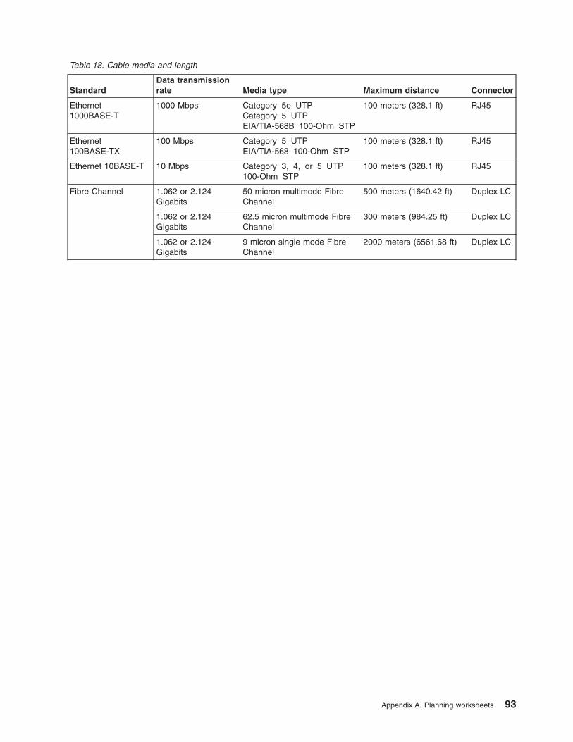
Table
18.
Cable
media
and
length
Standard
Data
transmission
rate
Media
type
Maximum
distance
Connector
Ethernet
1000BASE-T
1000
Mbps
Category
5e
UTP
Category
5
UTP
EIA/TIA-568B
100-Ohm
STP
100
meters
(328.1
ft)
RJ45
Ethernet
100BASE-TX
100
Mbps
Category
5
UTP
EIA/TIA-568
100-Ohm
STP
100
meters
(328.1
ft)
RJ45
Ethernet
10BASE-T
10
Mbps
Category
3,
4,
or
5
UTP
100-Ohm
STP
100
meters
(328.1
ft)
RJ45
Fibre
Channel
1.062
or
2.124
Gigabits
50
micron
multimode
Fibre
Channel
500
meters
(1640.42
ft)
Duplex
LC
1.062
or
2.124
Gigabits
62.5
micron
multimode
Fibre
Channel
300
meters
(984.25
ft)
Duplex
LC
1.062
or
2.124
Gigabits
9
micron
single
mode
Fibre
Channel
2000
meters
(6561.68
ft)
Duplex
LC
Appendix
A.
Planning
worksheets
93

Power
worksheet
This
section
describes
how
to
determine
ac
power
needs
and
ordering
power
cords.
1.
Record
the
number
of
blades
to
be
installed
in
this
BladeCenter
unit.
2.
Use
the
following
chart
to
determine
the
number
of
required
power
modules
(2
or
4).
Power
modules
Number
of
blades
Required
in
product
order
Maximum
ac
input
power
Number
of
PDU
outlets
Number
of
power
cords
1
and
2
1
to
6
Power
modules
1
and
2
2
kVA
2
outlets
2
(1
per
module)
1,
2,
3,
and
4
7
to
14
Power
modules
1,
2,
3,
and
4
4
kVA
4
outlets
4
(1
per
module)
3.
Record
the
number
of
power
modules
per
BladeCenter
unit
=
_____
4.
Record
the
number
of
BladeCenter
units
to
be
installed
in
this
rack
_____
5.
Multiply
the
number
recorded
in
Steps
3
and
4
to
obtain
the
total
number
of
required
power
cords
and
power
outlets
_____
94
BladeCenter
Type
8677:
Planning
and
Installation
Guide

Appendix
B.
Configuration
Worksheets
Use
the
worksheets
in
this
appendix
to
configure
the
components
for
your
BladeCenter
unit.
Information
about
each
of
the
worksheets
is
provided
in
Chapter
3,
“Deployment
considerations,”
on
page
21.
Management
module
configuration
worksheet
Fill
out
this
worksheet
to
provide
the
information
needed
to
configure
the
management
module.
For
information
on
filling
out
the
worksheet,
see
“Management
module
configuration
planning”
on
page
73
and
the
BladeCenter
Type
8677
Installation
and
User’s
Guide.
General
Settings
Management
module
name
Contact
name
Physical
location
Clock
settings
Login
profiles
Login
ID
Password
Authority
level
R/O
R/W
External
network
interface
(eth0)
Interface
__
Enabled
__
Disabled
DHCP
__
DHCP
with
rollover
to
static
__
DHCP
only
__
Static
IP
only
Hostname
Static
IP
configuration
(configure
only
if
DHCP
is
disabled)
©
Copyright
IBM
Corp.
2003
95
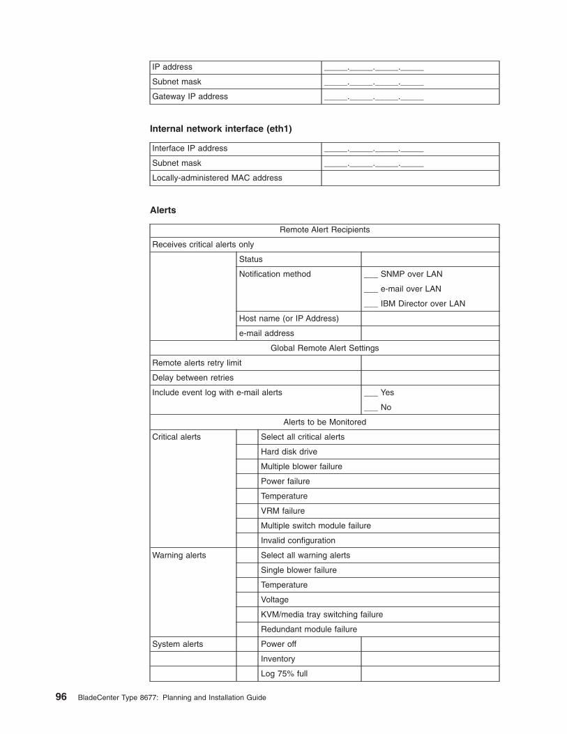
IP
address
_____._____._____._____
Subnet
mask
_____._____._____._____
Gateway
IP
address
_____._____._____._____
Internal
network
interface
(eth1)
Interface
IP
address
_____._____._____._____
Subnet
mask
_____._____._____._____
Locally-administered
MAC
address
Alerts
Remote
Alert
Recipients
Receives
critical
alerts
only
Status
Notification
method
___
SNMP
over
LAN
___
over
LAN
___
IBM
Director
over
LAN
Host
name
(or
IP
Address)
address
Global
Remote
Alert
Settings
Remote
alerts
retry
limit
Delay
between
retries
Include
event
log
with
alerts
___
Yes
___
No
Alerts
to
be
Monitored
Critical
alerts
Select
all
critical
alerts
Hard
disk
drive
Multiple
blower
failure
Power
failure
Temperature
VRM
failure
Multiple
switch
module
failure
Invalid
configuration
Warning
alerts
Select
all
warning
alerts
Single
blower
failure
Temperature
Voltage
KVM/media
tray
switching
failure
Redundant
module
failure
System
alerts
Power
off
Inventory
Log
75%
full
96
BladeCenter
Type
8677:
Planning
and
Installation
Guide

Network
protocols
SNMP
SNMP
agent
__
Enable
__
Disable
SNMP
traps
__
Enable
__
Disable
Community
name
Host
name
(or
IP
address)
SMTP
Host
name
(or
IP
address)
DNS
DNS
__
Enable
__
Disable
DNS
Server
IP
address
1
_____._____._____._____
DNS
Server
IP
address
2
_____._____._____._____
DNS
Server
IP
address
3
_____._____._____._____
Security
Secure
Socket
Layer
(SSL)
__
Enabled
__
Disabled
Certificates
__
Self-signed
__
Provided
by
a
certificate
authority
Appendix
B.
Configuration
Worksheets
97

Ethernet
switch
module
configuration
worksheet
Fill
out
the
worksheet
in
this
section
for
each
Ethernet
switch
module
you
plan
to
have
in
your
BladeCenter
unit.
For
information
on
filling
out
the
worksheet,
see
“Ethernet
switch
module
configuration
planning”
on
page
74
and
the
BladeCenter
Ethernet
Switch
Module
Installation
and
User’s
Guide.
Switch
settings
Name
Location
Local
contact
Get
IP
from
(manual,
BOOTP,
DHCP)
IP
address
____.____.____.____
Subnet
mask
____.____.____.____
Default
gateway
____.____.____.____
Switch
GVRP
(enabled
or
disabled)
MAC
address
aging
timer
(enabled
or
disabled)
Aging
time
(10
to
1,000,000
seconds)
Telnet
time
out
Telnet
sessions
(1
to
4)
Enable
external
ports
for
management
Port
settings
Port
State
Speed
(Mbps)
Duplex
Flow
control
E
D
10
100
1000
Auto
H
F
E
D
1
x
x
2
x
x
3
x
x
4
x
x
5
x
x
6
x
x
7
x
x
8
x
x
9
x
x
10
x
x
11
x
x
12
x
x
13
x
x
14
x
x
Ex1
Ex2
Ex3
Ex4
98
BladeCenter
Type
8677:
Planning
and
Installation
Guide

SNMP
management
station
IP
settings
IP
address
_____._____._____._____
IP
address
_____._____._____._____
IP
address
_____._____._____._____
SNMP
community
strings
and
trap
recipients
Community
string
Rights
Status
Trap
recipient
Status
R
R/W
E
D
E
D
____.____.____.____
____.____.____.____
____.____.____.____
____.____.____.____
____.____.____.____
____.____.____.____
____.____.____.____
____.____.____.____
____.____.____.____
____.____.____.____
____.____.____.____
____.____.____.____
____.____.____.____
____.____.____.____
____.____.____.____
____.____.____.____
Ethernet
switch
module
user
accounts
User
ID
Password
Access
level
Root
User
User+
USERID
PASSW0RD
x
Appendix
B.
Configuration
Worksheets
99

TFTP
servers
Table
19.
TFTP
servers
File
TFTP
server
address
Path
and
file
name
Download
configuration
____.____.____.____
Firmware
code
____.____.____.____
Upload
configuration
____.____.____.____
History
log
____.____.____.____
802.1Q
VLANs
VLAN
ID
(VID):
____________________
VLAN
name:
_______________________
Port
Tag
None
Egress
Forbidden
1
2
3
4
5
6
7
8
9
10
11
12
13
14
EX1
EX2
EX3
EX4
802.1Q
port
settings
Port
Port
VLAN
ID
Priority
Ingress
filter
GVRP
1
2
3
4
5
6
7
100
BladeCenter
Type
8677:
Planning
and
Installation
Guide

Port
Port
VLAN
ID
Priority
Ingress
filter
GVRP
8
9
10
11
12
13
14
EX1
EX2
EX3
EX4
IGMP
snooping
settings
Switch
IGMP
Snooping
(enabled
or
disabled)
__
Enabled
__
Disabled
Querier
State
__
Non-Querier
__
V1–querier
__
V2–querier
Query
Interval
(1
to
65,500
seconds)
Maximum
response
(1
to
25
seconds)
Robustness
variable
(1
to
255)
Multicast
forwarding
table
entries
Port
MAC
address
VID
None
Egress
1
2
3
4
5
6
7
8
9
10
11
12
13
14
EX1
EX2
Appendix
B.
Configuration
Worksheets
101

Port
MAC
address
VID
None
Egress
EX3
EX4
Port
mirroring
settings
Source
port
Mirroring
status
(enabled/disabled)
Target
port
Ingress
Egress
1
2
3
4
5
6
7
8
9
10
11
12
13
14
EX1
EX2
EX3
EX4
Spanning
tree
settings
Status
(enabled
or
disabled)
Maximum
age
(6
to
40
seconds)
Hello
time
(1
to
10
seconds)
Forward
delay
(4
to
30
seconds)
Priority
(0
to
65,535)
STP
port
settings
Port
Cost
Priority
Fast
STP
STP
state
E
D
E
D
1
2
3
4
102
BladeCenter
Type
8677:
Planning
and
Installation
Guide

Port
Cost
Priority
Fast
STP
STP
state
E
D
E
D
5
6
7
8
9
10
11
12
13
14
EX1
EX2
EX3
EX4
Class
of
service
configuration
Output
Priority
Method
Queue:
__
Enabled
__
Disabled
__
Weighted
Round
Robin
Class
Weight
(0
to
16)
Max
latency
High
priority
Med-H
priority
Med-L
priority
Low
priority
802.1p
priority
mapping
802.1p
priority
mapping
class:
__
Low
priority
__
Med-low
priority
__
Med-high
priority
__
High
priority
Priority
levels
Low
Med-L
Med-H
High
0
Appendix
B.
Configuration
Worksheets
103

Priority
levels
Low
Med-L
Med-H
High
1
2
3
4
5
6
7
Diffserv
mapping
Diffserv
mapping
__
Enabled
__
Disabled
Class
__
Low
priority
__
Med-low
priority
__
Med-high
priority
__
High
priority
Code
point
Class
Code
point
Class
Low
M-L
M-H
High
Low
M-L
M-H
High
0
32
1
33
2
34
3
35
4
36
5
37
6
38
7
39
8
40
9
41
10
42
11
43
12
44
13
45
14
46
15
47
16
48
104
BladeCenter
Type
8677:
Planning
and
Installation
Guide

Code
point
Class
Code
point
Class
Low
M-L
M-H
High
Low
M-L
M-H
High
17
49
18
50
19
51
Distribution
method
Packet
type
Src
MAC
Dest
MAC
Src
&
Dest
MAC
Src
IP
Dest
IP
Src
&
Dest
IP
Non-IP
N/A
N/A
N/A
IP
Port
trunking
Group
ID
Port
Method
EX1
EX2
EX3
EX4
Trunk
Disabled
802.3ad
link
aggregation
Link
Aggregation
Control
Protocol
(enabled
or
disabled):
__________
System
Priority
(LACP
switch
ID):
______________
Port
Priority
Administrator
key
Operator
key
Mode
Enabled
Disabled
EX1
EX2
EX3
EX4
Appendix
B.
Configuration
Worksheets
105

Blade
server
configuration
planning
Fill
out
this
worksheet
for
the
blade
servers
in
your
BladeCenter
unit.
For
information
on
filling
out
the
worksheet,
see
“Blade
server
configuration
planning”
on
page
83
and
the
BladeCenter
HS20
Installation
and
User’s
Guide.
Bay
Num
Blade
server
name
IDE
Controller
Ethernet
Controller
Startup
(boot)
sequence
E
D
E
D
IDE
drive
1
IDE
drive
2
CD-
ROM
Diskette
Network
1
2
3
4
5
6
7
8
9
10
11
12
13
14
Table
20.
Blade
server
operating
systems/applications
Bay
Num
Blade
server
name
Operating
system/applications
1
2
3
4
5
6
7
8
9
10
11
12
13
14
106
BladeCenter
Type
8677:
Planning
and
Installation
Guide

Appendix
C.
Notices
This
publication
was
developed
for
products
and
services
offered
in
the
U.S.A.
IBM
may
not
offer
the
products,
services,
or
features
discussed
in
this
document
in
other
countries.
Consult
your
local
IBM
representative
for
information
on
the
products
and
services
currently
available
in
your
area.
Any
reference
to
an
IBM
product,
program,
or
service
is
not
intended
to
state
or
imply
that
only
that
IBM
product,
program,
or
service
may
be
used.
Any
functionally
equivalent
product,
program,
or
service
that
does
not
infringe
any
IBM
intellectual
property
right
may
be
used
instead.
However,
it
is
the
user’s
responsibility
to
evaluate
and
verify
the
operation
of
any
non-IBM
product,
program,
or
service.
IBM
may
have
patents
or
pending
patent
applications
covering
subject
matter
described
in
this
document.
The
furnishing
of
this
document
does
not
give
you
any
license
to
these
patents.
You
can
send
license
inquiries,
in
writing,
to:
IBM
Director
of
Licensing
IBM
Corporation
North
Castle
Drive
Armonk,
NY
10504-1785
U.S.A.
INTERNATIONAL
BUSINESS
MACHINES
CORPORATION
PROVIDES
THIS
PUBLICATION
“AS
IS”
WITHOUT
WARRANTY
OF
ANY
KIND,
EITHER
EXPRESS
OR
IMPLIED,
INCLUDING,
BUT
NOT
LIMITED
TO,
THE
IMPLIED
WARRANTIES
OF
NON-INFRINGEMENT,
MERCHANTABILITY
OR
FITNESS
FOR
A
PARTICULAR
PURPOSE.
Some
jurisdictions
do
not
allow
disclaimer
of
express
or
implied
warranties
in
certain
transactions,
therefore,
this
statement
may
not
apply
to
you.
This
information
could
include
technical
inaccuracies
or
typographical
errors.
Changes
are
periodically
made
to
the
information
herein;
these
changes
will
be
incorporated
in
new
editions
of
the
publication.
IBM
may
make
improvements
and/or
changes
in
the
product(s)
and/or
the
program(s)
described
in
this
publication
at
any
time
without
notice.
Any
references
in
this
publication
to
non-IBM
Web
sites
are
provided
for
convenience
only
and
do
not
in
any
manner
serve
as
an
endorsement
of
those
Web
sites.
The
materials
at
those
Web
sites
are
not
part
of
the
materials
for
this
IBM
product,
and
use
of
those
Web
sites
is
at
your
own
risk.
IBM
may
use
or
distribute
any
of
the
information
you
supply
in
any
way
it
believes
appropriate
without
incurring
any
obligation
to
you.
Edition
notice
©
COPYRIGHT
INTERNATIONAL
BUSINESS
MACHINES
CORPORATION,
2002.
All
rights
reserved.
Note
to
U.S.
Government
Users
—
Documentation
related
to
restricted
rights
—
Use,
duplication
or
disclosure
is
subject
to
restrictions
set
forth
in
GSA
ADP
Schedule
Contract
with
IBM
Corp.
©
Copyright
IBM
Corp.
2003
107

Trademarks
The
following
terms
are
trademarks
of
International
Business
Machines
Corporation
in
the
United
States,
other
countries,
or
both:
Active
Memory
Predictive
Failure
Analysis
Active
PCI
PS/2
Active
PCI-X
ServeRAID
Alert
on
LAN
ServerGuide
BladeCenter
ServerProven
C2T
Interconnect
TechConnect
Chipkill
Tivoli
EtherJet
Tivoli
Enterprise
e-business
logo
Update
Connector
FlashCopy
Wake
on
LAN
IBM
XA-32
IntelliStation
XA-64
Light
Path
Diagnostics
X-Architecture
NetBAY
XceL4
Netfinity
XpandOnDemand
NetView
xSeries
OS/2
WARP
Lotus,
Lotus
Notes,
SmartSuite,
and
Domino
are
trademarks
of
Lotus
Development
Corporation
and/or
IBM
Corporation
in
the
United
States,
other
countries,
or
both.
ActionMedia,
LANDesk,
MMX,
Pentium,
and
ProShare
are
trademarks
of
Intel
Corporation
in
the
United
States,
other
countries,
or
both.
Microsoft,
Windows,
and
Windows
NT
are
trademarks
of
Microsoft
Corporation
in
the
United
States,
other
countries,
or
both.
UNIX
is
a
registered
trademark
of
The
Open
Group
in
the
United
States
and
other
countries.
Java
and
all
Java-based
trademarks
and
logos
are
trademarks
or
registered
trademarks
of
Sun
Microsystems,
Inc.
in
the
United
States,
other
countries,
or
both.
Linux
is
a
registered
trademark
of
Linus
Torvalds.
Other
company,
product,
or
service
names
may
be
trademarks
or
service
marks
of
others.
Important
notes
Processor
speeds
indicate
the
internal
clock
speed
of
the
microprocessor;
other
factors
also
affect
application
performance.
CD-ROM
drive
speeds
list
the
variable
read
rate.
Actual
speeds
vary
and
are
often
less
than
the
maximum
possible.
108
BladeCenter
Type
8677:
Planning
and
Installation
Guide

When
referring
to
processor
storage,
real
and
virtual
storage,
or
channel
volume,
KB
stands
for
approximately
1000
bytes,
MB
stands
for
approximately
1
000
000
bytes,
and
GB
stands
for
approximately
1
000
000
000
bytes.
When
referring
to
hard
disk
drive
capacity
or
communications
volume,
MB
stands
for
1
000
000
bytes,
and
GB
stands
for
1
000
000
000
bytes.
Total
user-accessible
capacity
may
vary
depending
on
operating
environments.
Maximum
internal
hard
disk
drive
capacities
assume
the
replacement
of
any
standard
hard
disk
drives
and
population
of
all
hard
disk
drive
bays
with
the
largest
currently
supported
drives
available
from
IBM.
Maximum
memory
may
require
replacement
of
the
standard
memory
with
an
optional
memory
module.
IBM
makes
no
representation
or
warranties
regarding
non-IBM
products
and
services
that
are
ServerProven®,
including
but
not
limited
to
the
implied
warranties
of
merchantability
and
fitness
for
a
particular
purpose.
These
products
are
offered
and
warranted
solely
by
third
parties.
IBM
makes
no
representations
or
warranties
with
respect
to
non-IBM
products.
Support
(if
any)
for
the
non-IBM
products
is
provided
by
the
third
party,
not
IBM.
Some
software
may
differ
from
its
retail
version
(if
available),
and
may
not
include
user
manuals
or
all
program
functionality.
Electronic
emission
notices
Federal
Communications
Commission
(FCC)
statement
Note:
This
equipment
has
been
tested
and
found
to
comply
with
the
limits
for
a
Class
A
digital
device,
pursuant
to
Part
15
of
the
FCC
Rules.
These
limits
are
designed
to
provide
reasonable
protection
against
harmful
interference
when
the
equipment
is
operated
in
a
commercial
environment.
This
equipment
generates,
uses,
and
can
radiate
radio
frequency
energy
and,
if
not
installed
and
used
in
accordance
with
the
instruction
manual,
may
cause
harmful
interference
to
radio
communications.
Operation
of
this
equipment
in
a
residential
area
is
likely
to
cause
harmful
interference,
in
which
case
the
user
will
be
required
to
correct
the
interference
at
his
own
expense.
Properly
shielded
and
grounded
cables
and
connectors
must
be
used
in
order
to
meet
FCC
emission
limits.
IBM
is
not
responsible
for
any
radio
or
television
interference
caused
by
using
other
than
recommended
cables
and
connectors
or
by
unauthorized
changes
or
modifications
to
this
equipment.
Unauthorized
changes
or
modifications
could
void
the
user’s
authority
to
operate
the
equipment.
This
device
complies
with
Part
15
of
the
FCC
Rules.
Operation
is
subject
to
the
following
two
conditions:
(1)
this
device
may
not
cause
harmful
interference,
and
(2)
this
device
must
accept
any
interference
received,
including
interference
that
may
cause
undesired
operation.
Industry
Canada
Class
A
emission
compliance
statement
This
Class
A
digital
apparatus
complies
with
Canadian
ICES-003.
Avis
de
conformité
à
la
réglementation
d’Industrie
Canada
Appendix
C.
Notices
109

Cet
appareil
numérique
de
la
classe
A
est
conforme
à
la
norme
NMB-003
du
Canada.
Australia
and
New
Zealand
Class
A
statement
Attention:
This
is
a
Class
A
product.
In
a
domestic
environment
this
product
may
cause
radio
interference
in
which
case
the
user
may
be
required
to
take
adequate
measures.
United
Kingdom
telecommunications
safety
requirement
Notice
to
Customers
This
apparatus
is
approved
under
approval
number
NS/G/1234/J/100003
for
indirect
connection
to
public
telecommunication
systems
in
the
United
Kingdom.
European
Union
EMC
Directive
conformance
statement
This
product
is
in
conformity
with
the
protection
requirements
of
EU
Council
Directive
89/336/EEC
on
the
approximation
of
the
laws
of
the
Member
States
relating
to
electromagnetic
compatibility.
IBM
cannot
accept
responsibility
for
any
failure
to
satisfy
the
protection
requirements
resulting
from
a
nonrecommended
modification
of
the
product,
including
the
fitting
of
non-IBM
option
cards.
This
product
has
been
tested
and
found
to
comply
with
the
limits
for
Class
A
Information
Technology
Equipment
according
to
CISPR
22/European
Standard
EN
55022.
The
limits
for
Class
A
equipment
were
derived
for
commercial
and
industrial
environments
to
provide
reasonable
protection
against
interference
with
licensed
communication
equipment.
Attention:
This
is
a
Class
A
product.
In
a
domestic
environment
this
product
may
cause
radio
interference
in
which
case
the
user
may
be
required
to
take
adequate
measures.
Taiwanese
Class
A
warning
statement
110
BladeCenter
Type
8677:
Planning
and
Installation
Guide

Japanese
Voluntary
Control
Council
for
Interference
(VCCI)
statement
Power
cords
For
your
safety,
IBM
provides
a
power
cord
with
a
grounded
attachment
plug
to
use
with
this
IBM
product.
To
avoid
electrical
shock,
always
use
the
power
cord
and
plug
with
a
properly
grounded
outlet.
IBM
power
cords
used
in
the
United
States
and
Canada
are
listed
by
Underwriter’s
Laboratories
(UL)
and
certified
by
the
Canadian
Standards
Association
(CSA).
For
units
intended
to
be
operated
at
230
volts
(U.S.
use):
Use
a
UL-listed
and
CSA-certified
cord
set
consisting
of
a
minimum
18
AWG,
Type
SVT
or
SJT,
three-conductor
cord,
a
maximum
of
15
feet
in
length
and
a
tandem
blade,
grounding-type
attachment
plug
rated
15
amperes,
250
volts.
For
units
intended
to
be
operated
at
230
volts
(outside
the
U.S.):
Use
a
cord
set
with
a
grounding-type
attachment
plug.
The
cord
set
should
have
the
appropriate
safety
approvals
for
the
country
in
which
the
equipment
will
be
installed.
Appendix
C.
Notices
111

112
BladeCenter
Type
8677:
Planning
and
Installation
Guide

Index
Aacoustical
noise
emissions
3
acoustics
module
42
airflow
50
auxiliary-device
port
11
Bblade
server
configuration
worksheet
106
blade
server
planning
worksheet
86
BladeCenter
planning
worksheet
88
BladeCenter
unitcomponents
9
BTU
51
Ccable
specifications
17
cabling
51
Ethernet
port
32
cabling
planning
worksheet
92
CD-ROM
drivespecifications
3
Class
A
electronic
emission
notice
109
clearances,
rack
41
componentsBladeCenter
unit
9
major
17
connectorinput/output
11
Universal
Serial
Bus
11
connectorsEthernet
11
Universal
Serial
Bus
11
cooling
3,
51
Ddata
transmission
rates
17
dimensions
41
DIMMsspecifications
13
supported
13
diskette
drivespecifications
3
Eelectrical
input
3,
13,
49
electronic
emission
Class
A
notice
109
environment
3,
13
Ethernetcable
specifications
17
configuring
settings
32
port,
cabling
32
Ethernet
(continued)standards
17
Ethernet
connector
11
Ethernet
switch
module
configuration
worksheet
98
Ethernet-link
status
LED
32
FFCC
Class
A
notice
109
features
17
BladeCenter
unit
3
server
1
flash
memory
18
floor
space
41
Ggeneral
requirements
17
Hheat
output
3,
51
humidity
50
Iinstallation
times
72
integrated
functions
13
Kkeyboard
port
11
LLEDs
Ethernet-link
status
32
front
view
10
rear
view
10
Mmajor
components
17
management
module
configuration
worksheet
95
memoryspecifications
13
memory
module
specifications
13
microprocessor
specifications
13
Nnoise
42
notes,
important
108
noticeselectronic
emission
109
FCC,
Class
A
109
©
Copyright
IBM
Corp.
2003
113

Pperformance
requirements
18
physical
installation
times
72
planning
worksheets
85
8677
BladeCenter
88
blade
server
86
blade
server
configuration
106
cabling
92
Ethernet
switch
module
configuration
98
management
module
configuration
95
power
94
rack
90
pointing
device
port
11
portauxiliary-device
11
keyboard
11
pointing
device
11
remote
management
11
port
See
connector
11
port
specifications
17
power
connections
51
example
1
52
example
10
71
example
2
54
example
3
56
example
4
58
example
5
61
example
6
65
example
7
68
example
8
69
example
9
70
power
considerations
45
power
cords
111
power
distribution
units
45
power
modulespecifications
3
power
planning
worksheet
94
power
supplyspecifications
3
productdata
12
Rrack
planning
worksheet
90
racks
43
remote
management
port
11
Ssize
3
specifications
3
data
transmission
rates
17
network
cable
17
performance
requirements
18
ports
17
protocols
19
standards
17
technical
17
standards
17
status
lights
10
Ttechnical
specifications
17
temperature
3,
50
trademarks
108
transmission
rates
17
UUnited
States
electronic
emission
Class
A
notice
109
United
States
FCC
Class
A
notice
109
Universal
Serial
Bus
connector
11
Vvideo
controller
3
Wweight
3
weight,
BladeCenter
unit
41
weight,
rack
limits
43
worksheets,
planning
85
8677
BladeCenter
88
blade
server
86
blade
server
configuration
106
cabling
92
Ethernet
switch
module
configuration
98
management
module
configuration
95
power
94
rack
90
114
BladeCenter
Type
8677:
Planning
and
Installation
Guide


����
Printed
in
USA
GA27-4327-01