bock compressors f/f-nh 3 assembly instructions 09702_03_2012_gb.pdf · 2.3 type code 3 areas of...
TRANSCRIPT

D
GB
F
E
1
0970
2-03
.201
2-DG
bF
F2, F3 F2 NH3, F3 NH3F4, F5 F4 NH3, F5 NH3F14/1166, F14/1366 F14/1166 NH3, F14/1366 NH3F16/1751, F16/2051 F16/1751 NH3, F16/2051 NH3
FX2, FX3FX4, FX5FX14/1166, FX14/1366FX16/1751, FX16/2051
engineering for a better world GEA Refrigeration Technologies
Bock Compressors F/F-NH3
Assembly instructions

2
D
GB
F
E
0970
2-03
.201
2-DG
bF
1 Safety 4 1.1 Identificationofsafetyinstructions 1.2 Qualificationsrequiredofpersonnel 1.3 Generalsafetyinstructions 1.4 AdditionalsafetyinstructionsNH3 1.5 Intendeduse 2 Product description 6 2.1 Shortdescription 2.2 Nameplate 2.3 Typecode 3 Areas of application F 9 3.1 RefrigerantsF,F-NH3 3.2 Oilcharge 3.3 Operatinglimits 4 Areas of application F-NH3 11 4.1 OilchargeNH3 4.2 OperatinglimitsNH3 5 Compressor assembly 12 5.1 Settingup 5.2Maximumpermissibleinclination 5.3 Pipeconnections 5.4 Pipes 5.5 Layingsuctionanddischargelines 5.6 Operatingtheshut-offvalves 5.7 Operatingmodeofthelockableserviceconnections 5.8Drive 5.9 Oilsumpheating(standardbyF4,F5,F14andF16) 6 Commissioning 18 6.1 Preparationsforstart-up 6.2 Pressureresistancetest 6.3 Leaktest 6.4 Evacuation 6.5 Refrigerantcharge 6.6 Shaftseal 6.7 Shaftsealchange 6.8 Start-up 6.9 Avoidingslugging 7 Maintenance 21 7.1 Preparation 7.2 Worktobecarriedout 7.3 Sparepartsrecommendation 7.4 SparepartsrecommendationNH3 7.5 Accessories 7.6 Excerptfromthelubricanttable 7.7 Decommissioning 8 Technical data F2-F16 23 9 Technical data F2 NH3-F16 NH3 24 10 Dimensions and connections F 25 11 Dimensions and connections F-NH3 33 12 Declaration of installation 41 13 Service 42
About these instructionsReadtheseinstructionsbeforeassemblyandbeforeusingthecompressor.Thiswillavoidmisunder-standings andpreventdamage.Improperassemblyanduseofthecompressorcanleadtoseriousorfatalinjury.Observethesafetyinstructionscontainedintheseinstructions.Theseinstructionsmustbepassedontotheendcustomeralongwiththeunitinwhichthecompres-sorisinstalled.
GEABockGmbH
72636Frickenhausen
Manufacturer
Contact
GEABockGmbH
Benzstraße7
72636Frickenhausen
Germany
Telephone +49702294540
Fax +4970229454-137
www.bock.de

D
GB
F
E
3
0970
2-03
.201
2-DG
bF
Contents Page
1 Safety 4 1.1 Identificationofsafetyinstructions 1.2 Qualificationsrequiredofpersonnel 1.3 Generalsafetyinstructions 1.4 AdditionalsafetyinstructionsNH3 1.5 Intendeduse 2 Product description 6 2.1 Shortdescription 2.2 Nameplate 2.3 Typecode 3 Areas of application F 9 3.1 RefrigerantsF,F-NH3 3.2 Oilcharge 3.3 Operatinglimits 4 Areas of application F-NH3 11 4.1 OilchargeNH3 4.2 OperatinglimitsNH3 5 Compressor assembly 12 5.1 Settingup 5.2Maximumpermissibleinclination 5.3 Pipeconnections 5.4 Pipes 5.5 Layingsuctionanddischargelines 5.6 Operatingtheshut-offvalves 5.7 Operatingmodeofthelockableserviceconnections 5.8Drive 5.9 Oilsumpheating(standardbyF4,F5,F14andF16) 6 Commissioning 18 6.1 Preparationsforstart-up 6.2 Pressureresistancetest 6.3 Leaktest 6.4 Evacuation 6.5 Refrigerantcharge 6.6 Shaftseal 6.7 Shaftsealchange 6.8 Start-up 6.9 Avoidingslugging 7 Maintenance 21 7.1 Preparation 7.2 Worktobecarriedout 7.3 Sparepartsrecommendation 7.4 SparepartsrecommendationNH3 7.5 Accessories 7.6 Excerptfromthelubricanttable 7.7 Decommissioning 8 Technical data F2-F16 23 9 Technical data F2 NH3-F16 NH3 24 10 Dimensions and connections F 25 11 Dimensions and connections F-NH3 33 12 Declaration of installation 41 13 Service 42

4
D
GB
F
E
0970
2-03
.201
2-DG
bF
1 | Safety
1.2 Qualificationsrequiredofpersonnel
INFO! This operating manual describes compressors that are suitable for both F-gases and for NH3.
Specific information and characteristics for using NH3 are indicated at the corresponding location with the following symbols:
NH3
NH3
1.1 Identificationofsafetyinstructions:
DANGER!
WARNING!
CAUTION!
ATTENTION!
INFO!
Indicates a dangerous situation which, if not avoided, will cause immediate fatal or serious injury.
Indicates a dangerous situation which, if not avoided, may cause fatal or serious injury.
Indicates a dangerous situation which, if not avoided, may cause fairly severe or minor injury.
Indicates a situation which, if not avoided, may cause property damage.
Important information or tips on simplifying work.
WARNING! Inadequatelyqualifiedpersonnelposes the riskof accidents, the consequencebeingseriousorfatalinjury.Workoncompressorsis therefore reserved for personnel with the qualifications listed below: •For example, a refrigeration technician, refrigeration mechatronic
engineer. As well as professions with comparable training, whichenablespersonneltoassemble,install,maintainandrepairrefrigerationandair-conditioningsystems.Personnelmustbecapableofassessingtheworktobecarriedoutandrecognisinganypotentialdangers.

D
GB
F
E
5
0970
2-03
.201
2-DG
bF
1 | Safety
These assembly instructions describe the standard version of the compressor named in the titleandNH3manufacturedbyBock.TheBockrefrigeratingcompressorare intendedfor installation inamachine(withintheEUaccordingtotheEUDirectives2006/42/ECMachineryDirective,97/23/ECPressureEquipmentDirective).Commissioningispermissibleonlyifthecompressorhasbeeninstalledinaccordancewiththeseas-semblyinstructionsandtheentiresystemintowhichitisintegratedhasbeeninspectedandapprovedinaccordancewithlegalregulations.
Onlytherefrigerantspecifiedintheseinstructionsmaybeused.
Any other use of the compressor is prohibited!
1.5 Intended use
WARNING! The compressor may not be used in potentially explosive environments!
1.4 Additional safety instructions NH3
NH3 ATTENTION! •High toxicity, intense odour (MAK 50 ppm) •Explosivebetween15and30vol.% in theair.Due to thehigh
ignition energy and temperature, the risk of explosion, however, is rated as low. So there are no special explosion protection measuresarerequired.
•However, the national safety regulations, accident preventionregulations, technical regulations as well as specific regulations (EN 378 etc.) must be observed.
•NH3 steam is lighter than air and therefore disperses upwards. •AllkeydirectivesaresummarisedintheareafortheAiFresearch
project 9404B "Safety of ammonia refrigeration systems". •NH3 corrodes copper materials and non-ferrous metals and is incompatible with a number of plastics. •Proofofpersonnel'sspecificexpertiseforinstallation, commissioning, operation and service.
1.3 General safety instructions
DANGER! •Refrigerating compressors are pressurised machines and as such call for heightened caution and care in handling.
The maximum permissible overpressure must not be exceeded, even for testing purposes.
WARNING! •Risk of burns! Depending on the operating conditions, surface temperatures of over 60°C on the discharge side or below 0°C on the suction side can be reached.

6
D
GB
F
E
0970
2-03
.201
2-DG
bF
2 | Product description
Opentypecompressorsforexternaldrive(V-beltorcoupling) withoilpumplubrication
2.1 Short description
DimensionandconnectionvaluescanbefoundinChapter10
BasedontheFcompressorseries,aspeciallymodifiedselectionofcompressorsisavailableforusewiththerefrigerantR717.
Important differences from the basic compressor F: Pistonswiththree-ringassembly Con-rodwithadditionaloilsupplyoiltothesmallend Valveplatewithoptimisedpressureunit Shut-offvalvewithsteelconnectorforweldedjoints Allconnectionsaredesignedascompressionjointsforsteelpipes F14 NH3andF16NH3withincreasedoilvolumeduetothehigherbaseplate Specialoilfillingfor NH3: FuchsRenisoKC68
Short description NH3
F2, F3
F2
Suctionshut-offvalve
CylindercoverValveplate
Shaftseal
Shaftend
Compressorhousing
Baseplate
Dischargeshut-offvalve
Fig.1
Oilsightglass

D
GB
F
E
7
0970
2-03
.201
2-DG
bF
2 | Product description
F4, F5
DimensionandconnectionvaluescanbefoundinChapter10
F5
F16
F14, F16
Fig.2
Suctionshut-offvalve
Valveplate
Baseplate
Nameplate
Cylindercover
Dischargeshut-offvalve
Shaftseal
Shaftend
Compressorhousing
Fig.3
Transporteyelet
Dischargeshut-offvalve
Cylindercover
Compressorhousing
Baseplate
Valveplate
Suctionshut-offvalve
Leakoildrainhose
Shaftseal
Shaftend
Transporteyelet

8
D
GB
F
E
0970
2-03
.201
2-DG
bF
2 | Product description
/F 14 1166 NH3X
Fig.4
2.2 Name plate (example)
2.3 Type code (example)
¹)X-Esteroilcharge(HFCrefrigerantR134a,R404A/R507,R407C)²) IndicationonlyatF14,F16
NH3version
Sweptvolume ²)
Size
Oilcharge ¹)
Series
123456
FX16/2051
SE5519/28
1 Typedesignation2 Machinenumber3 Rotationspeedminimumwithacorrespondingdisplacement4 Rotationspeedmaximum withacorrespondingdisplacement5 ND(LP):Max.admissibleoperatingpressureSuctionside HD(HP):Max.admissibleoperatingpressure
High-pressureside6 Oiltypechargedatfactory
Observe the limit of application diagrams!
GEA Bock GmbH72636 Frickenhausen, Germany

D
GB
F
E
9
0970
2-03
.201
2-DG
bF
3 | Areas of application F, F-NH3
ATTENTION! Compressor operation is possible within the operating limits shown in the diagrams. Please note the significance of the shaded areas. Thresholds should not be selected as design or continuous operating points. - Max. permissible discharge end temperature: 140°C -Max.permissibleswitchingfrequency:12x/h - A minimum running time of 3 min. steady-state condition
(continuous operation) must be achieved.
Avoid continuous operation near the threshold.
For operation with supplementary cooling: - Use only oils with high thermal stability.
For operation with capacity regulator: - The suction gas superheat temperature may need to be reduced
or set individuallywhen operating near to the threshold.
When operating in the vacuum range, there is a danger of air entering on the suction side. This can cause chemical reactions, a pressure rise in the condenser and an elevated compressed-gas temperature. Prevent the ingress of air at all costs!
Thecompressorsarefilledwiththefollowingoiltypeatthefactory:-forR134a,R404A/R507,R407C FUCHSRenisoTritonSE55 -forR22 FUCHSRenisoSP46Compressorswithesteroilcharge(FUCHSRenisoTritonSE55)aremarkedwithanXinthetypedesignation(e.g. FX16/2051).
3.1 Refrigerants• HFKW: R134a,R404A/R507,R407C• (H)FCKW: R22 NH3: R717
3.2 Oil charge
3.3 Operating limits
INFO! For refilling, we recommend the above oil types. Alternatives: see lubricants table, Chapter 7.6

10
D
GB
F
E
0970
2-03
.201
2-DG
bF
3| Areas of application F
Design for other areasonrequest
Permissiblerotationspeeds:
F2,F3: 960-1800¹/min
F4,F5: 500-1800¹/min
F14,F16: 700-1800¹/min
3.3 Operating limits
R134a
Fig.5
R404A/R507
Fig.6
R407C
Fig.7
R22
Fig.8
Unlimited applicationrange
Reducedsuctiongas temperature
Evaporatingtemperature(°C)
Condensingtemperature(°C)
Suctiongassuperheat(K)
Suctiongastemperature(°C)
Maximum admissible operating pressure (g)
High pressure side (LP/HP)1): 19/28 bar
1) LP=LowpressureHP=Highpressure
D
GB
F
E
11
0970
2-03
.201
2-DG
bF
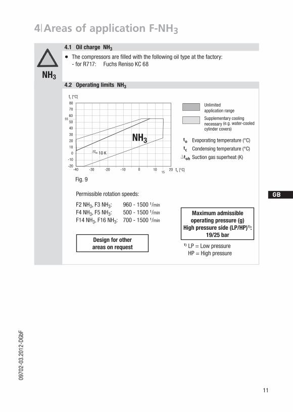
4| Areas of application F-NH3
Thecompressorsarefilledwiththefollowingoiltypeatthefactory:-forR717:FuchsRenisoKC68
4.1 Oil charge NH3
4.2 Operating limits NH3
NH3
Fig.9
NH3
Permissiblerotationspeeds:
F2NH3,F3NH3: 960-1500¹/min
F4NH3,F5NH3: 500-1500¹/min
F14NH3,F16NH3: 700-1500¹/min
Supplementarycoolingnecessary(e.g.water-cooledcylindercovers)
Unlimited applicationrange
Evaporatingtemperature(°C)
Condensingtemperature(°C)
Suctiongassuperheat(K)
Design for other areasonrequest
Maximum admissible operating pressure (g)
High pressure side (LP/HP)1): 19/25 bar
1) LP=LowpressureHP=Highpressure

12
D
GB
F
E
0970
2-03
.201
2-DG
bF
5| Compressor assembly
5.1 Setting up
Setuponanevensurfaceorframewithsufficientload-bearingcapacity.
Compressorsanddrivemotorsarebasicallyrigidandshouldbemountedtogetheronabaseframe.
Provideadequateclearanceformaintenancework. Provideadequateventilationforthedrivemotor.
Donotuseinadusty,dampatmosphereoracombustibleenvironment.
INFO! Newcompressorsarefactory-filledwithinertgas(3barnitrogen). Leave this service charge in the compressor for as long as possible and prevent the ingress of air.
Check the compressor for transport damage before starting any work.
Fig.12
Fig.13
Fig.14
Fig.10
F
E
D
C
B
A
1234
F
E
D
C
4 3 2 1
A
BTol.-Ang. DIN ISO 2768-mK
Ra Rz
Maß Passung Freigabe
Alternativbezug:Baumustergeprüft
Teil inaktiv
Lieferantenzeichnung
--
K.-Auftrag:PL:
Zeichnung ungültig
Entwicklungsstand
Teil keine Serie
120400
±0.5
über 0.5bis 6
Benzstraße 7 - 72636 Frickenhausen - Germany - www.bock.de
-
-Unbemaßte Radien:
-
Diese Zeichnung ist unser Eigentum!Sie darf ohne unsere Genehmigung weder nach-gebildet, vervielfältigt, oder Dritten Personen zu-gänglich gemacht werden. Der Nachbau nachdieser Zeichnung, oder an Hand der nach dieserZeichnung hergestellten Gegenstände durch denAbnehmer oder Dritte ist nicht gestattet.Wir behalten uns alle Rechte, gemäß DIN ISO 16016an dieser Zeichnung vor.
Bearb.DatumÄnderungs-Nr.
Werkstoff:
Ausgangsteil, bzw. Rohteil:-
-
Gepr.
NameDatum19.04.
WerkstückkantenDIN ISO 13715
Ersatz für:
Ersetzt durch:
Erstellt2010
Geprüft
-
Kurz
Zone
1/x
Oberflächenbehandlung / Härte:-
Blatt:Änderungsbeschreibung
400Benennung:
±0.8
1000 30 6
-
±0.3
12030
±0.2
Zeichn.-Nr. Teile-Nr.
Oberflächenangaben ISO 1302
x.xxxx-xxxxx.x
Zust.Gußtoleranzen:
Gewicht: (kg)
±0.1
Maßstab:
1:1
Wasserwaagefür Indesign
Der Lieferant muß sicherstellen, dass die Ware ineinwandfreiem Zustand angeliefert wird (Korrosions-schutz, Verpackung für sicheren Transport).
Rz 25Rz 160
s
25
zyxwut
0,05 Rz 1,60,30,71,62 Rz 166,3 Rz 63 Rz 6,3Rz 12,5
F:\u
ser\k
urz\
3D S
ache
n\3D
Tei
le\Z
eich
nung
en\W
asse
rwaa
ge
Transportandsuspensionunitontheeyebolt(Fig.11,F14toF16)ordirectonthedischargelinevalve(Fig.10,F2toF5).
WARNING! Movecompressorsonlywithhoiststhathaveadequateload-bearingcapacity.
Fittings (e.g. pipe holders, additional units etc.) on the compressor are permissible onlyfollowingconsultationwithBock.
Setuponanevensurfaceorframewithsufficientload-bearingcapacity.Useall4fasteningpoints.
Correctsetupofthecompressorandmountingofthebeltdrivearedecisiveforrunningcomfort,operatingsafetyandtheservicelifeofthecompressor.
Fig.11

D
GB
F
E
13
0970
2-03
.201
2-DG
bF
5| Compressor assembly
5.4 Pipes
Pipesandsystemcomponentsmustbecleananddryinsideandfreeofscale,swarfandlayersofrustandphosphate.Onlyuseair-tightparts.
Lay pipes correctly. Suitable vibration compensatorsmust be provided to prevent pipes being crackedandbrokenbyseverevibrations.
Ensureaproperoilreturn. Keeppressurelossestoanabsoluteminimum.
5.3 Pipe connections
The pipe connectionshavesteppedinternaldiameterssothatpipeswithstandardmillimetreandinchdimensionscanbeused.Theconnectiondiametersoftheshut-offvalvesaredesignedformaximumcompressoroutput.Therequiredpipecross-sectionmustbematchedto the capacity. The same applies for non-return valves.Therequiredtighteningtorquefortheflangeconnectionis60Nm.Fig.16:Stepped
internaldiameters
5.2 Maximum permissible inclination
ATTENTION! Poor lubrication can damage the compressor. Respect the stated values.
Fig.15
A A
a a
A A
a a
ATTENTION! Overheating can damage the valve. Remove the pipe supports from the valve for soldering. Only solder using inert gas to inhibit oxidation products (scale).
A max.30°, max.2minutes
a max.15°,continuousoperation

14
D
GB
F
E
0970
2-03
.201
2-DG
bF
5| Compressor assembly
5.6 Operating the shut-off valves
5.5 Laying suction and discharge lines
INFO! Proper layout of the suction and discharge lines directly after the compressor is integral to the system’s smooth running and vibration behaviour.
ATTENTION! Improperly installed pipes can cause cracks and tears, the result being a loss of refrigerant.
A rule of thumb:Alwayslaythefirstpipesectionstartingfromtheshut-offvalvedownwardsand parallel to the drive shaft.
Fig.17RigidFixedpointAsshortas
possible
Valve spindle seal
Beforeopeningorclosingtheshut-offvalve,releasethevalvespindlesealbyapprox.¼ofaturncounter-clockwise.
Afteractivatingtheshut-offvalve,re-tightentheadjustablevalvespindlesealclockwise.
Fig.18 Fig.19
loosen
tighten

D
GB
F
E
15
0970
2-03
.201
2-DG
bF
5| Compressor assembly
5.7 Operating mode of the lockable service connections
Pipeconnection
Fig.20Opening the shut-off valve:Spindle:turntotheleft(counter-clockwise)asfarasitwillgo. —> Theshut-offvalveisthenfullyopenandtheserviceconnectionisclosed.Theconnectionwhichisnotlockableisprovidedforsafetydevices.
Fig.21Opening the service connectionSpindle:½ - 1 rotationtotheright (clockwise). —> Theserviceconnectionisthenopenandtheshut-offvalveisalsoopen.Theconnectionwhichisnotlockableisprovidedforsafetydevices.
Serviceconnectionclosed
Serviceconnectionopened
ConnectionblockedSpindle
ConnectionopenSpindle Pipeconnection

16
D
GB
F
E
0970
2-03
.201
2-DG
bF
5| Compressor assembly
5.8 Drive
ThecompressorsoftheFseriescanbedrivenbyV-beltsordirectlybyshaftcouplings.
V-belt: Properassemblyofbeltdrive:
- Thepulleysofcompressoranddrivemotormustbefirmlymountedandinline. -OnlyuseV-beltswithcalibratedlengths. -Selectaxisspacing,V-beltlengthandbeltpre-tensionaccordingtotheinstructionsissuedby
theV-beltmanufacturer.Avoidbeltfluttering. -Checkbeltpre-tensionafterrunning-intime.Direct drive with shaft coupling: Directdrivewithshaftcouplingsdemandshighlyprecisealigningofcompressorshaftand
motorshaft. UsetheBockshaftcouplings„WK“andobservetheenclosedassemblyinstructions.
CAUTION! Mount suitable safeguards when driving the compressor by means of V-belts or shaft couplings!
ATTENTION! Faulty alignment results in premature failure of the coupling and bearing damage!

D
GB
F
E
17
0970
2-03
.201
2-DG
bF
5| Compressor assembly
Whenthecompressorisatastandstill,refrigerantdiffusesintothelubricationoilofthecompressorhousing,dependingonpressureandambienttemperature.Thisreducesthelubricationcapacityoftheoil.Whenthecompressorstartsup,therefrigerantcontainedintheoilevaporatesoutthroughthereductioninpressure.Theconsepuencescanbelackoflubrication,foamingandmigrationoftheoil,whichcaneventuallyleadtocompressordamage.
Topreventthis,theoilcanbeheatedviaanoilsumpheater.
Operation: OilsumpheaterONatstandstillofthecompressor. OilsumpheaterOFFduringoperationofthecompressor
Connection: Oilsumpheatermustbeconnectedviaanauxiliarycontact(orparallelwiredauxiliarycontact)ofthemotorcontactortoaseparateelectriccircuit.
5.9 Oil sump heating
WARNING! The oil sump heater must not be connected to the electrical circuit of the safety control chain !
Oil sump heater: 230 V – 1 – 50/60Hz, IP65
Type F2 F3 F4 F5 F14 F16
Electricalpower (Watt)
40 60 80 80 140 140
INFO! Same electrical performance even on NH3 compressorsNH3

18
D
GB
F
E
0970
2-03
.201
2-DG
bF
6| Commissioning
6.2 Pressure strength test
6.1 Preparations for start-up
6.3 Leak test
6.4 Evacuation
INFO! To protect the compressor against inadmissible operating conditions, high pressure and low pressure pressostats are mandatory on the installation side.
Thecompressorhasundergonetrialsinthefactoryandallfunctionshavebeentested.Therearethereforenospecialrunning-ininstructions.
Check the compressor for transport damage!
Firstevacuatethesystem andthenincludethe compressor in the evacuation process. Relievethecompressorpressure. Openthesuctionanddischargelinevalves. Evacuatethesuctionanddischargepressuresidesusingthevacuumpump. Attheendoftheevacuationprocess,thevacuumshouldbe<1.5mbarwhenthepumpisswitchedoff. Repeattheprocessasoftenasisrequired.
DANGER! Risk of bursting! The compressor must never be pressurised using oxygen or other technical gases!
The maximum permissible overpressure of the compressor must not be exceeded at any time during the testing process (see name plate data)! Do not mix any refrigerant with the testing medium (N2), as this could cause the ignition limit to shift into the critical range.
Thecompressorhasbeenfactory-testedforpressureresistance.Thefollowingmustbeobservediftheentireplantissubjectedtoanadditionalpressurestrengthtest:
TesttherefrigerationcircuitaccordingtoEN378-2oracorrespondingsafetystandard. Thepressurestrengthtestisbestcarriedoutusingdrynitrogen(N2).
DANGER! Risk of bursting! Do not mix any refrigerant with the testing medium (N2), as this could cause the ignition limit to shift into the critical range.
CarryouttheleaktestoftherefrigeratingsysteminaccordancewithEN378-2oracorresponding safetystandardwithout including the compressor.

D
GB
F
E
19
0970
2-03
.201
2-DG
bF
6| Commissioning
CAUTION! Wear personal protective clothing such as goggles and protective gloves!
Makesurethatthesuctionanddischargelinevalvesareopen.
Withthecompressorswitchedoff,addtheliquidrefrigerantdirectlytothecondenserorreceiver,breakingthevacuum.
Iftherefrigerantneedstoppingupafterstartingthecompressor,itcanbetoppedupinvapourformonthesuctionside,or,takingsuitableprecautions,alsoinliquidformattheinlettotheevaporator.
6.5 Refrigerant charge
ATTENTION! Avoidoverfillingthesystemwithrefrigerant! To avoid shifts in concentration, zeotropic refrigerant blends
mustalwaysonlybefilledintotherefrigeratingplantinliquidform.
Donotpourliquidcoolantthroughthesuctionlinevalveon the compressor. It is not permissible to mix additives with the oil and refrigerant.
6.6 Shaft seal
ATTENTION! Failure to observe the following instructions can cause loss of refrigerant and damage to the shaft seal!
INFO! The shaft seal seals and lubricates with oil. An oil leakage of 0.05 ml per operating hour is therefore normal. This applies particularly during the run-in phase (200 - 300 h).
ThecompressortypesF14andF16areequippedwithaleakoildrain hose (see chapter 10 and 11). The leak oil is continually discharged through the leak oil drain hose. To collect the leak oil, a receptacle is to be provided by the plant operator. Dispose of the leak oil in accordance with the valid national regulations.
Thecompressorshaft issealedtooutsideusingashaftseal.Thesealingelementrotateswiththeshaft.Thefollowingisespeciallyimportanttoensuringfault-freeoperation: Thecompleterefrigerantcircuitmustbecorrectlyexecutedandcleaninside. Heavyshocksandvibrationstotheshaftaswellascontinuouscyclicoperationaretobeavoided. Thesealingsurfacescansticktogetherduringprolongeddowntimes(e.g.winter).Therefore,run
thesystemevery4weeksfor10minutes.

20
D
GB
F
E
0970
2-03
.201
2-DG
bF
6| Commissioning
Aschangingtheshaftsealinvolvesopeningtherefrigerantcircuit,thisisrecommendedonlyifthesealislosingrefrigerant.Replacingtheshaftsealisdescribedinthesparepartkitconcerned.
6.7 Shaft seal change
6.8 Start-up
WARNING! Ensure that both shut-off valves are open before starting the compressor!
Checkthatthesafetyandprotectiondevices(pressureswitch,motorprotection,electricalcontactprotectionmeasures,etc.)areallfunctioningproperly.
Switchonthecompressorandallowtorunforaminimumof10min. Checktheoillevelby:Theoilmustbevisibleinthesightglass.
ATTENTION!Iflargerquantitiesofoilhavetobetoppedup,thereisariskofoilhammer effects. If this is the case check the oil return!
6.9 Avoiding slugging
ATTENTION! Slugging can damage the compressor and cause coolant to leak.
To prevent slugging: Thecompleterefrigerationsystemmustbeproperlydesigned. Allcomponentsmustbecompatiblyratedwitheachotherwithregardtooutput (particularlytheevaporatorandexpansionvalves).
Suctiongassuperheatatthecompressorinputshould be min. 7 - 10 K.(checkthesetting oftheexpansionvalve).
Thesystemmustreachastateofequilibrium. Particularlyincriticalsystems(e.g.severalevaporatorpoints),measuresarerecommendedsuchasreplacementofliquidtraps,solenoidvalveintheliquidline,etc. There should be no movement of coolant whatsoever while the compressor is at a standstill.

D
GB
F
E
21
0970
2-03
.201
2-DG
bF
7| Maintenance
Type F2 F3 F4 F5F14/1166F14/1366
F16/1751F16/2051
Designation Ref. No.
Setgaskets 08069 08070 08071 08072 08492 08493
Shaftseal 08001 08001 08008 08008 08444 08012
Valveplateset 08314 08198 08198 08436 08498 08498
Oilpump 08043 08043 08044 08044 08795 08795
Oilsumpheater 08423 08424 08425 08425 08426 08426
Only use original Bock spare parts!
7.3 Spare parts recommendation
7.2 Work to be carried outToguaranteeoptimumoperatingsafetyandservicelifeofthecompressor,we recommendperfor-mingserviceandcheckingworkatregularintervalsoftime: Oil change: - Inseriesplantsproducedinthefactorynotmandatory. - Infieldinstallationsoroperatingintheapplicationlimitrange,firstoilchangeafterapprox.
100-200operatinghours,thenapprox.every3yearsor10,000-12,000operatinghours. Disposeofoldoilaccordingtotheregulations,observenationalregulations.
Annual checks:Oillevel,tightness,runningnoise,pressures,temperatures,functionofauxiliarydevicessuchasaoilsumpheater,pressureswitch.Complywiththenationalregulations!
7.1 Preparation
WARNING! Before starting any work on the compressor: Switch off the compressor and secure it to prevent a restart. Relieve compressor of system pressure. Preventairfrominfiltratingthesystem! After maintenance has been performed: Connect safety switch. Evacuate compressor. Release switch lock.

22
D
GB
F
E
0970
2-03
.201
2-DG
bF
7.6 Excerpt from the lubricant table
Theoilgradefilledasstandardinthefactoryisnotedonthename plate. This oil grade should be used preferably.Alternativestothisarelistedinthefollowingexcerptfromourlubricanttable.
AccessoriesavailablecanbefoundintheF-Catalogue(BockRef.-No.96023)or ontheInternetatwww.bock.de.
7.5 Accessories
Type F2 NH3 F3 NH3 F4 NH3 F5 NH3F14/1166NH3F14/1366NH3
F16/1751NH3F16/2051NH3
Designation Ref. No.
Setgaskets 08069 08070 08071 08072 08492 08493
Shaftseal 08001 08001 08008 08008 08444 08012
ValveplatesetNH3 08841 08842 08842 08843 08844 08844
Oilpump 08043 08043 08044 08044 08799 08799
Oilsumpheater 08423 08424 08425 08425 08426 08426
Only use original Bock spare parts!
7.4 Spare parts recommendation NH3
NH3
7.7 Decommissioning
7| Maintenance
Refrigerant Bock series oil grades Recommendedalternatives
HFKW(e.g.R134a, R404A/R507,R407C)
Fuchs Reniso Triton SE 55
FUCHSRenisoTritonSEZ32ICIEmkarateRL32H,S
MOBILArcticEAL32SHELLClavusR32
HFCKW(e.g.R22) Fuchs Reniso SP 46
FUCHSReniso,z.B.KM,HP,SP32SHELLClavusSD22-12TEXACOCapellaWF46
NH3
Fuchs Reniso KC 68forfloodedoperation Fuchs Reniso Synth 68forapplicationsusingaplateheatexchanger
-
Informationonfurthersuitableoilsonrequest.
Closetheshut-offvalvesonthecompressor.Draintherefrigerant(itmustnotbedischargedintotheenvironment)anddisposeofitaccordingtotheregulations.Whenthecompressorisdepressurised,undothefasteningscrewsoftheshut-offvalves.Removethecompressorusinganappropriatehoist.Disposeoftheoilinsideinaccordancewiththeapplicablenationalregulations.

D
GB
F
E
23
0970
2-03
.201
2-DG
bF
8| Technical data F2 - F16No
. of
cylin
ders
Disp
lace
men
t(1
450/
1740
1 /m
in)
Wei
ght ²
)Co
nnec
tions
¹)Oi
l cha
rge
Rota
tion
spee
d ra
nge
Disc
harg
elin
e DV
Suct
ion
line
SV
m3 /h
kgmm I inch
mm I inch
ltr.
1 /min
F22
10,50/1
2,60
1816
I 5/ 8
16 I
5/ 8
0,8
960-
1800
F320
,30/2
4,30
2822
I 7/ 8
28
I 1
1 /8
1,5
F44
40,50/4
8,60
51 2
8 I
1 1 /
8 3
5 I
1 3 /
82,6
500-
1800
F573
,70/8
8,40
85 3
5 I
1 3 /
82x35
I 1
3 /8
3,8
F14/1166
F14/13
664
101,40
/12
1,70
119,00
/14
2,80
149
42
I 1
5 /8
54
I 2
1 /8
3,8
700-
1800
F16/17
51F1
6/20
516
152,20
/18
2,60
178,40
/21
4,10
175
42
I 1
5 /8
54
I 2
1 /8
5,0
700-
1800
Type
¹) fors
olde
ringjoint
²) in
stand
ardde
sign

24
D
GB
F
E
0970
2-03
.201
2-DG
bF
9| Technical data F2-NH3 - F16-NH3No
. of
cylin
ders
Disp
lace
men
t(1
450
1 /m
in)
Wei
ght ²
)Co
nnec
tions
¹)Oi
l cha
rge
Rota
tion
spee
d ra
nge
Disc
harg
elin
e DV
Suct
ion
line
SV
m3 /h
kgmm
mm
ltr.
1 /min
F2NH 3
210
,50
1818
180,8
960-
1500
F3NH 3
20,30
2825
301,5
F4NH 3
440
,50
5130
382,6
500-
1500
F5NH 3
73,70
8538
2x38
3,8
F14/1166
NH 3
F14/13
66NH 3
410
1,50
118,90
158
4960
6,3
700-
1500
F16/17
51NH 3
F16/20
51NH 3
615
2,20
178,40
183
4960
7,5
700-
1500
Type
¹) fors
olde
ringjoint
²) in
stand
ardde
sign

D
GB
F
E
25
0970
2-03
.201
2-DG
bF
10| Dimensions and connections F
Compressor type F2
Shaft end F2
Fig.22Dimensionsinmm
Fig.23Dimensionsinmm
DimensionsforviewXseepage32
Woodruffkey
Cone
101
114 77
ca.255
123
195
310
ca.3
40
134
152
4xØ9
15
B1
B/L
B
DV
A1
SV
A
H/D1
K
F/G
X

26
D
GB
F
E
0970
2-03
.201
2-DG
bF
10| Dimensions and connections F
Compressor type F3
Shaft end F3
Fig.24Dimensionsinmm
Fig.25Dimensionsinmm
DimensionsforviewXseepage32
Woodruffkey
Cone
118
130 96.5
ca.315
90
135
175
200
4xØ9
230
17
135
360
ca.4
00
DV
B/L
A
A1
SV
C/E
D/D1/H
K
F/G
B1
X

D
GB
F
E
27
0970
2-03
.201
2-DG
bF
10| Dimensions and connections F
Compressor type F4
Shaft end F4
Fig.26Dimensionsinmm
Fig.27Dimensionsinmm
DimensionsforviewXseepage32
Woodruffkey
Cone
4x 11
ca.305
170
ca.455
130ca.225
K
F
J
H
D
B DVB1LSV
A
A1
C/E
D1
395
210240
25
ca.4
30
X

28
D
GB
F
E
0970
2-03
.201
2-DG
bF
10| Dimensions and connections F
Compressor type F5
Shaft end F5
Fig.28Dimensionsinmm
Fig.29Dimensionsinmm
DimensionsforviewXseepage32
Woodruffkey
Cone
4xØ11
150 169
ca.470
ca.4
65
D
D1
H
25170
3404
30
240
270
246
ca.355B1
LB
DV
SV
A
A1
C/E
K
F
J
X

D
GB
F
E
29
0970
2-03
.201
2-DG
bF
10| Dimensions and connections F
Compressor type F14 F14/1166 F14/1366
Shaft end F14
Fig.30Dimensionsinmm
Dimensionsin()=withelevatedbaseplate
Woodruffkey
Cone
362 124
4xØ13.5
290
320
ca.5
10
(560)
448
(498)
432
(482)
180
(230)
20
ca.415
121.5290
342
ca.530
X Y Y
SV
DV
L
A
B2
D
B
H
D1
A1
P
B1
B
C
E
K
F
J
ÖV1
Fig.31Dimensionsinmm
DimensionsforviewX,Yseepage32
Leakoil drainhose

30
D
GB
F
E
0970
2-03
.201
2-DG
bF
10| Dimensions and connections F
Compressor type F16 F16/1751 F16/2051
Shaft end F16
Fig.32Dimensionsinmm
Dimensionsin()=withelevatedbaseplate
Woodruffkey
Cone
290143.5290
B
A1
B1
B
C
K
FJ
ÖV1
PD1
H E
YY
(520
)
20320
452
(502
)20
0 (2
50)47
0
ca.515
ca.5
35 (5
85)
4x 13.5
A
SV
DV
L
B2
D
X
363
342ca.580
170
Fig.33Dimensionsinmm
DimensionsforviewX,Yseepage32
Leakoil drainhose
D
GB
F
E
31
0970
2-03
.201
2-DG
bF
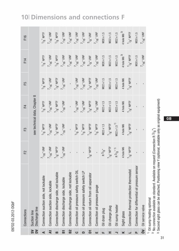
Conn
ectio
nsF2
F3F4
F5F1
4F1
6
SV DV
Suctionline
Disch
arge
line
seetech
nicald
ata,Cha
pter8
ACo
nnectio
nsuctionside
,notlo
ckab
le7 /
16"UNF
1 /8"
NPT
F1 /
8" NPT
F1 /
8" NPT
F1 /
8" NPT
F1 /
8" NPT
F
A1Co
nnectio
nsuctionside
,locka
ble
7 /16
"UNF
7 /16
"UNF
7 /16
"UNF
7 /16
"UNF
7 /16
"UNF
7 /16
"UNF
BCo
nnectio
ndischa
rgeside
,notlo
ckab
le1 /
8"NPT
F1 /
8"NPT
F1 /
8"NPT
F1 /
8"NPT
F1 /
8" NPT
F1 /
8" NPT
F
B1Co
nnectio
ndischa
rgeside
,locka
ble
7 /16
"UNF
7 /16
"UNF
7 /16
"UNF
7 /16
"UNF
7 /16
"UNF
7 /16
"UNF
B2
Conn
ectio
ndischa
rgeside
,notlo
ckab
le-
--
-7 /
16"UNF
7 /16
"UNF
CCo
nnectio
noilp
ressuresafetyswitc
hO
IL-
1 /8"
NPT
F7 /
16"UNF
7 /16
"UNF
7 /16
"UNF
7 /16
"UNF
DCo
nnectio
noilp
ressuresafetyswitc
hLP
-1 /
8" NPT
F7 /
16"UNF
7 /16
"UNF
7 /16
"UNF
7 /16
"UNF
D1
Conn
ectio
noilreturnfrom
oilsepa
rator
1 /8"
NPT
F1 /
8"NPT
F1 /
8"NPT
F1 /
8"NPT
F5 /
8"UNF
5 /8"
UNF
ECo
nnectio
noilp
ressurega
uge
-1 /
8" NPT
F7 /
16"UNF
7 /16
"UNF
7 /16
"UNF
7 /16
"UNF
FOildrainplug
R 3 /
8"M22
x1,5
M22
x1,5
M22
x1,5
M26
x1,5
M26
x1,5
HOilch
arge
plug
1 /8"
NPT
F1 /
8"NPT
FM22
x1,5
M22
x1,5
M22
x1,5
M22
x1,5
JOilsumphe
ater
R 3 /
8" 1)
M22
x1,51)
M22
x1,5
M22
x1,5
M22
x1,5
M22
x1,5
KSigh
tglass
4ho
leM
64ho
leM
64ho
leM
64ho
leM
64ho
leM
63)
4ho
leM
63)
LCo
nnectio
nthermalprotectionthermostat
1 /8"
NPT
F1 /
8"NPT
F1 /
8"NPT
F1 /
8"NPT
F1 /
8"NPT
F1 /
8"NPT
F
PCo
nnectio
n ford
ifferen
tialo
ilpressuresen
sor
--
--
M20
x1,5
M20
x1,5
ÖVOilservicevalve
--
--
7 /16
"UNF
7 /16
"UNF
1) O
ilsumphe
atingop
tiona
l2) N
oco
nnec
tionavailableasstand
ard.Availableon
requ
est(Co
nnec
tionR
3 /8"
)3) Secon
dsigh
tglasscan
beattach
ed,P
osition
ingview
Y(o
ptiona
l,availableon
lyasoriginalequ
ipmen
t)
10| Dimensions and connections F

32
D
GB
F
E
0970
2-03
.201
2-DG
bF
10.1 View X, Y
•Oilsightglass •Connectionfacilityforparalleloperation
Position view X:F2,F3,F4,F5,F14,F164holeoilsightglass
Position view Y:F14,F16Secondoilsightglasscanbeattachedasanoption(availableasoriginalequipmentonly)
50
45°
90°
4xM6,10mmdeep
mm
10| Dimensions and connections
Connection facilities
Operationwithoillevelregulator
Fig.34
Operationwithcommonoil-gasbalancepipe
example:3compressorsinparallel
Art.Nr.80462BOCKadapterforoillevelregulator,fitsthemakesESK,AC+R,CARLY.3holefasteneronthesideoftheoillevelregulator4holefasteneronthesideofthecompressor
Art.Nr.80463BOCKadapterforoil-gasregulator, singledesign, 4holesteelconnectorforPipeØ35mm,fitsallsightglasspositions. 1itempercompressorrequired.

D
GB
F
E
33
0970
2-03
.201
2-DG
bF
11| Dimensions and connections F-NH3
Compressor type F2 NH3
Shaft end F2 NH3
Fig.35Dimensionsinmm
Fig.36Dimensionsinmm
DimensionsforviewXseepage40
Woodruffkey
Cone
4xØ9
134
15215
123
ca.3
30
10595
114 77
ca.265
300
195
B1
B/L
DV
SV
A1
H/D1
K
F/G
X
4xØ9
134
152
15
123
ca.3
30
10595
114 77
ca.265
300
195
B1
B/L
DV
SV
A1
H/D1
K
F/G
X

34
D
GB
F
E
0970
2-03
.201
2-DG
bF
11| Dimensions and connections F-NH3
Compressor type F3 NH3
Shaft end F3 NH3
Fig.37Dimensionsinmm
Fig.38Dimensionsinmm
DimensionsforviewXseepage40
Woodruffkey
Cone
130 96.5
ca.345
175
200
4xØ9
118
120
75
230
17
135
ca.3
65
ca.3
90
B
L
SV
C/E
D/D1/H
K
F/G
DV
B1
A
A1
X

D
GB
F
E
35
0970
2-03
.201
2-DG
bF
11| Dimensions and connections F-NH3
Compressor type F4 NH3
Shaft end F4 NH3
Fig.39Dimensionsinmm
Fig.40Dimensionsinmm
DimensionsforviewXseepage40
Woodruffkey
Cone
11(4x)
ca.305
Cotes en mm
Offener Verdichter / Open type compressor / Compresseur ouvert
Sous réserve de toutes modifikations
Maße in mmDimension in mm
Teile-Nr. 09877
Subject to change without notice
V= Schneidringverschraubung
Dimensions du bout d' arbre sur fiche technique N° art.09980
F 4 NH3
Änderungen vorbehalten
1.0851-11726.0 k
Maße für Wellenende auf Datenblatt Teile-Nr.09980
Typ
Dimensions of shaft end on data sheet item no.09980
S= Schweißanschluß S= Welded connection S= Raccordement soudé
Teile Nr.11726
V= Connection à vis taraudeusseV= Cutting rind connection
Anschlüsse Connections RaccordsSV Saugabsperrventil, Rohr Suction line valve, tube Vanne d' arrêt d' aspiration, de tuyau mm 38x32 SDV Druckabsperrventil, Rohr Discharge line valve, tube Vanne d' arrêt de refoulement, de tuyau mm 30x24 SA Anschluß Saugseite, nicht absperrbar Connection suction side, not lockable Raccord côté aspiration, non obturable mm 6 V
A1 Anschluß Saugseite, absperrbar Connection suction side, lockable Raccord côté aspiration, obturable mm 6 VB Anschluß Druckseite, nicht absperrbar Connection discharge side, not lockable Raccord côté refoulement, non obturable mm 6 V
B1 Anschluß Druckseite, absperrbar Connection discharge side, lockable Raccord côté refoulement, obturable mm 6 VC Anschluß Öldrucksicherheitsschalter OIL Connection oil pressure safety switch OIL Raccord pressostat de sécurité d'huile OIL mm 6 VD Anschluß Öldrucksicherheitsschalter LP Connection oil pressure safety switch LP Raccord pressostat de sécurité d'huile LP mm 6 V
D1 Anschluß Ölrückführung vom Ölabscheider Connection oil return from oil separator Raccord retour d'huile de séparateur d'huile mm 10 VE Anschluß Öldruckmanometer Connection oil pressure gauge Raccord du manomètre de pression d'huile mm 6 VF Stopfen Ölablaß Oil drain plug Bouchon de vidange d'huile mm M22x1,5G Stopfen Ölsumpfheizung Oil sump heater plug Bouchon chauffage de carter d’huile mm M22x1,5H Stopfen Ölfüllung Oil charge plug Bouchon de remplissage d'huile mm M22x1,5K Schauglas Sight glass Voyant mm -L Anschluß Wärmeschutzthermostat Connection thermal protection thermostat Raccord de thermostat de protection thermique Zoll 1/8 NPTF
schutz, Verpackung für sicheren Transport).
F
E
D
C
B
A
F
E
D
C
4 3 2 1
A
B
5678
12345678
Abnehmer oder Dritte ist nicht gestattet.
Numéro de plan:
Oberflächenbehandlung / Härte:
1R
evis
ions
durc
hlau
f:
Tol.-Ang. DIN ISO 2768-mK
Ra Rz
Änderung betrifft Blatt 2, Übernahme auf 3D
LayhMaß Passung Freigabe
Alternativbezug:Baumustergeprüft
Teil inaktiv
F4/NH3Lieferantenzeichnung
-K.-Auftrag:PL:
Zeichnung ungültig
Entwicklungsstand
Teil keine Serie
120400
±0.5
über 0.5bis 6
-
Benzstraße 7 - 72636 Frickenhausen - Germany - www.bock.de
-
LayhGrass12.10.067563-
-
k
-
Zeichn.-Nr. / Drawing no. /
Wir behalten uns alle Rechte, gemäß DIN ISO 16016
Rz 12,5 Rz 6,3Rz 636,3 Rz 162
an dieser Zeichnung vor.
Bearb.DatumÄnderungs-Nr.
Werkstoff:
Unbemaßte Radien:
Ausgangsteil, bzw. Rohteil:
-
Gepr.
Name
-
Datum
15.09.
WerkstückkantenDIN ISO 13715
Ersatz für:
Ersetzt durch:
10.09.2009
ErstelltGeprüft
1.0851-11726.0j CAD
BüttnerBuck
1/2
Zone
-
Blatt:
Änderungsbeschreibung
400Benennung:
±0.8
1000 30
15.09.
-
±0.3
12030
±0.2
Zeichn.-Nr. Teile-Nr.
6
1.0851-11726.0
Zust.
Gußtoleranzen:
Gewicht: (kg)
±0.1
Oberflächenangaben ISO 1302
Maßstab:
%
Offener Verdichter
Rz 25Rz 160
s
25
zyxwut
0,05 Rz 1,60,30,71,6
Diese Zeichnung ist unser Eigentum!Sie darf ohne unsere Genehmigung weder nach-gebildet, vervielfältigt, oder Dritten Personen zu-gänglich gemacht werden. Der Nachbau nachdieser Zeichnung, oder an Hand der nach dieserZeichnung hergestellten Gegenstände durch den
Der Lieferant muß sicherstellen, dass die Ware ineinwandfreiem Zustand angeliefert wird (Korrosions-
G:\U
ser\G
rass
\Pro
jekt
e\W
elle
n_V
erdi
chte
r f. H
eege
r\FN
H3\
1172
6k-1
B
X
213130 169
ca.450
H
DVB1L
SV
A
A1
C/E
K
FG
D1
D
240210
170
ca.4
25
25
398

36
D
GB
F
E
0970
2-03
.201
2-DG
bF
11| Dimensions and connections F-NH3
Compressor type F5 NH3
Shaft end F5 NH3
Fig.41Dimensionsinmm
Fig.42Dimensionsinmm
DimensionsforviewXseepage40
Woodruffkey
Cone
4xØ11
150 169
ca.470
ca.4
85
B
240
270
ca.355
B1 DV
246
L
A1
H
D1
D
251
70
347
464
SV
C/E
K
F
G
A
X
4xØ11
150 169
ca.470
ca.4
85
B
240
270
ca.355
B1 DV
246
L
A1
H
D1
D
251
70
347
464
SV
C/E
K
F
G
A
X

D
GB
F
E
37
0970
2-03
.201
2-DG
bF
11| Dimensions and connections F-NH3
Compressor type F14 NH3 F14/1166 NH3 F14/1366 NH3
Shaft end F14 NH3
Fig.43Dimensionsinmm
Woodruffkey
Cone
290 121.5
342
ca.530
DV
L
A
B2
D
SV
4xØ13.5
290
320
A1
B1
B
E
C
K
G
F
ÖV1
B
H
D1
362 124 ca.415
230
482
498
ca.5
60
20
X YY
290 121.5
342
ca.530
DV
L
A
B2
D
SV
4xØ13.5
290
320
A1
B1
B
E
C
K
G
F
ÖV1
B
H
D1
362 124 ca.415
230
482
498
ca.5
60
20
X YY
Fig.44Dimensionsinmm
DimensionsforviewX,Yseepage40
Leakoil drainhose

38
D
GB
F
E
0970
2-03
.201
2-DG
bF
11| Dimensions and connections F-NH3
Compressor type F16 NH3 F16/1751 NH3 F16/2051 NH3
Shaft end F16 NH3
Fig.45Dimensionsinmm
Woodruffkey
Cone
290 143,5290
A
SV
DV
L
X
342
363 170
ca.580
F16/NH3
F
E
D
C
B
A
F
E
D
C
4 3 2 1
A
B
5678
12345678
Abnehmer oder Dritte ist nicht gestattet.
Numéro de plan:
Rev
isio
nsdu
rchl
auf:
1
-
Anschluss B in L und Anschluss L in B geändertStückliste überarbeitet, Erstellung Explosionsbild, Übernahme auf 3D
02.03.
Tol.-Ang. DIN ISO 2768-mK
LayhMaß Passung Freigabe
Alternativbezug:Baumustergeprüft
Teil inaktiv
Layh
Lieferantenzeichnung
-K.-Auftrag:PL:
Zeichnung ungültig
Entwicklungsstand
Teil keine Serie
120400
±0.5
über 0.5bis 6
08.10.09
Benzstraße 7 - 72636 Frickenhausen - Germany - www.bock.de
-
LayhGrassBüttner
schutz, Verpackung für sicheren Transport).
24.07.0975637552
--
Änderung betrifft Blatt 2ba
-
LayhZuder
Ra Rz
7476-
-
-
-
Zeichn.-Nr. / Drawing no. /
Wir behalten uns alle Rechte, gemäß DIN ISO 16016
Rz 12,5 Rz 6,3Rz 636,3 Rz 162
an dieser Zeichnung vor.
Bearb.DatumÄnderungs-Nr.
Werkstoff:
Unbemaßte Radien:
Ausgangsteil, bzw. Rohteil:
-
Gepr.
Name
02.03.09
Datum
02.03.
WerkstückkantenDIN ISO 13715
Ersatz für:
Ersetzt durch:
02.03.2009
ErstelltGeprüft
1.0851-11708.0 l 2D
ZuderBuck
1/3
Zone
-
Blatt:
Änderungsbeschreibung
400Benennung:
±0.8
1000 30
Oberflächenbehandlung / Härte:
-
±0.3
12030
±0.2
Zeichn.-Nr. Teile-Nr.
6
1.0851-11713.0
Zust.
Gußtoleranzen:
Gewicht: (kg)
±0.1
Oberflächenangaben ISO 1302
Maßstab:
%
Offener Verdichter
Rz 25Rz 160
s
25
zyxwut
0,05 Rz 1,60,30,71,6
Diese Zeichnung ist unser Eigentum!Sie darf ohne unsere Genehmigung weder nach-gebildet, vervielfältigt, oder Dritten Personen zu-gänglich gemacht werden. Der Nachbau nachdieser Zeichnung, oder an Hand der nach dieserZeichnung hergestellten Gegenstände durch den
Der Lieferant muß sicherstellen, dass die Ware ineinwandfreiem Zustand angeliefert wird (Korrosions-
G:\U
ser\G
rass
\Pro
jekt
e\W
elle
n_V
erdi
chte
r f. H
eege
r\FN
H3\
1171
3b-1
B1
C
D1
B
G
F
B
B2KH
ÖV1
E
A1
D
ca.
502
320
515
250
520
20
4x 13,5
ca.5
85
Maße für Wellenende auf Datenblatt Teile-Nr. 09980
Offener Verdichter / Open type compressors / Compresseurs ouverts
Y
Dimensions of shaft end on data sheet item no. 09980
Subject to change without noticeSous réserve de toutes modifications
Maße in mm
Änderungen vorbehalten
Dimensions du bout d'arbre sur fiche technique N°art. 09880
Cotes en mmDimensions in mm
V= SchneidringverschraubungS= Schweißanschluß
V= Cutting rind connectionS= Welded connection
V= Connection à vis taraudeusse
1.0851-11713.0 b
Oil service valveÖlserviceventil
Teile-Nr. 09880
S= Raccordement soudé
Y
mmVanne de vidange d'huile 6 V
Anschlüsse Connections RaccordsSV Saugabsperrventil, Rohr Suction line valve, tube Vanne d'arrêt d'aspiration, de tuyau mm 60x54 SDV Druckabsperrventil, Rohr Discharge line valve, tube Vanne d'arrêt de refoulement, de tuyau mm 49x42 SA Anschluß Saugseite, nicht absperrbar Connection suction side, not lockable Raccord côté aspiration, non obturable Zoll 1/8" NPTF
A1 Anschluß Saugseite, absperrbar Connection suction side, lockable Raccord côté aspiration, obturable mm 6 VB Anschluß Druckseite, nicht absperrbar Connection discharge side, not lockable Raccord côté refoulement, non obturable Zoll 1/8'' NPTF
B1 Anschluß Druckseite, absperrbar Connection discharge side, lockable Raccord côté refoulement, obturable mm 6 VB2 Anschluß Druckseite, nicht absperrbar Connection discharge side, not lockable Raccord côté refoulement, non obturable mm 6 VC Anschluß Öldrucksicherheitsschalter OIL Connection oil pressure safety switch OIL Raccord pressostat de sécurité d'huile OIL mm 6 VD Anschluß Öldrucksicherheitsschalter LP Connection oil pressure safety switch LP Raccord pressostat de sécurité d'huile LP mm 6 V
D1 Anschluß Ölrückführung vom Ölscheider Connection oil return from oil separator Raccord retour d'huile de séparateur d'huile mm 10 VE Anschluß Öldruckmanometer Connection oil pressure gauge Raccord du manomètre de pression d'huile mm 6 VF Stopfen Ölablaß Oil drain plug Bouchon de vidange d'huile mm M26x1,5G Stopfen Ölsumpfheizung Oil sump heater plug Bouchon chauffage du carter d'huile mm M22x1,5H Stopfen Ölfüllung Oil charge plug Bouchon de remplissage d'huile mm M22x1,5K Schauglas Sight glass Voyant mm -L Anschluß Wärmeschutzthermostat Connection thermal protection thermostat Raccord de thermostat de protection thermique Zoll 1/8" NPTF
ÖV 1
Typ Teile Nr.F16/1751 NH3 11708F16/2051 NH3 11713
Fig.46Dimensionsinmm
DimensionsforviewXseepage40
Leakoil drainhose

D
GB
F
E
39
0970
2-03
.201
2-DG
bF
Conn
ectio
nsF2
NH
3F3
NH
3F4
NH
3F5
NH
3F1
4NH
3F1
6NH
3
SV DV
Suctionline
Disch
arge
line
seetech
nicald
ata,Cha
pter8,F
-NH
3
ACo
nnectio
nsuctionside
,notlo
ckab
le-
Ø6V
1)Ø6V
1)Ø6V
1)1/8"NPT
F 1)
1/8"NPT
F 1)
A1Co
nnectio
nsuctionside
,locka
ble
Ø6V1)
Ø6V
1)Ø6V
1)Ø6V
1)Ø6V
1)Ø6V
1)
BCo
nnectio
ndischa
rgeside
,notlo
ckab
le1 /
8"NPT
FØ6V
1)Ø6V
1)Ø6V
1)1/8"NPT
F 1)
1/8"NPT
F 1)
B1Co
nnectio
ndischa
rgeside
,locka
ble
Ø6V1)
Ø6V
1)Ø6V
1)Ø6V
1)Ø6V
1)Ø6V
1)
B2
Conn
ectio
ndischa
rgeside
,notlo
ckab
le-
--
-Ø6V
1)Ø6V
1)
CCo
nnectio
noilp
ressuresafetyswitc
hO
IL-
Ø6V
1)Ø6V
1)Ø6V
1)Ø6V
1)Ø6V
1)
DCo
nnectio
noilp
ressuresafetyswitc
hLP
-Ø10V
1)Ø6V
1)Ø6V
1)Ø6V
1)Ø6V
1)
D1
Conn
ectio
noilreturnfrom
oilsepa
rator
Ø10V1)
Ø10V
1)Ø10V
1)Ø10V
1)Ø10V
1)Ø10V
1)
ECo
nnectio
noilp
ressurega
uge
-Ø6V
1)Ø6V
1)Ø6V
1)Ø6V
1)Ø6V
1)
FOildrainplug
R 3 /
8"M22
x1,5
M22
x1,5
M22
x1,5
M26
x1,5
M26
x1,5
GOilsumphe
aterplug
R 3 /
8"M22
x1,5
M22
x1,5
M22
x1,5
M22
x1,5
M22
x1,5
HOilch
arge
plug
Ø10V1)
Ø10V
1)M22
x1,5
M22
x1,5
M22
x1,5
M22
x1,5
KSigh
tglass
4ho
leM
64ho
leM
64ho
leM
64ho
leM
64ho
leM
62)
4ho
leM
6 2)
LCo
nnectio
nthermalprotectionthermostat
1 /8"
NPT
F1 /
8"NPT
F1 /
8"NPT
F1 /
8"NPT
F1 /
8"NPT
F1 /
8"NPT
F
ÖVOilservicevalve
--
--
Ø6V
1)Ø6V
1)
1)Com
pression
jointforsteelpipes
2) Secon
dsigh
tglasscan
beattach
ed,p
osition
ingview
Y(o
ptiona
l,on
lyasoriginalequ
ipmen
t)
11| Dimensions and connections F-NH3

40
D
GB
F
E
0970
2-03
.201
2-DG
bF
11.1 View X, Y
•Oilsightglass •Connectionfacilityforparalleloperation
Position view X:F2NH3,F3NH3,F4NH3,F5NH3,F14NH3,F16NH34holeoilsightglass
Position view Y:F14 NH3,F16NH3Secondoilsightglasscanbeattachedasanoption(availableasoriginalequipmentonly)
50
45°
90°
4xM6,10mmdeep
mm
Fig.47
11| Dimensions and connections F-NH3

D
GB
F
E
41
0970
2-03
.201
2-DG
bF
12| Declaration of installation
DECLARATION OF INSTALLATION
forusingthecompressorswithintheEuropeanUnion(inaccordancewithMachineryDirective2006/42/EC)
Themanufacturer: GEABockGmbH,Benzstraße7 D-72636Frickenhausen,Tel.:07022/9454-0
herebydeclaresthattherefrigeratingcompressor F2, F3, F4, F5, F14, F16 and F2 NH3, F3 NH3, F4 NH3, F5 NH3, F14 NH3, F16 NH3conformstotheessentialrequirementsofAnnexII1BoftheMachineryDirective2006/42/EC. Thefollowingharmonisedstandardshavebeenapplied:
ENISO12100-1ENISO12100-2EN12693EN349
Apartlycompletedmachinemayonlybeputintooperation,whenithasbeenestablishedthatthemachine,intowhichthepartlycompletedmachineistobeinstalled,conformstotheregulationsoftheMachineryDirective(2006/42/EC).
Themanufacturerundertakestotransmitelectronicallythespecialdocumentationrequiredbyindividualstatesforpartlycompletedmachineryuponrequest.
Thespecialtechnicaldocumentationrequiredforpartlycompletedmachineryhasbeencreated inaccordancewithAnnexVIIPartB.
Personresponsiblefordocumentationis: WolfgangSandkötter,Benzstraße7,72636Frickenhausen.
Frickenhausen,01.11.2011 ppa.WolfgangSandkötter,ChiefDevelopmentOfficer

42
D
GB
F
E
0970
2-03
.201
2-DG
bF
13| Service
Dearcustomer,
Bockcompressorsaretop-quality,reliableandservice-friendlyqualityproducts. Ifyouhaveanyquestionsaboutinstallation,operationandaccessories,pleasecontactourtechnicalserviceorspecialistwholesalerand/orourrepresentative.TheBockserviceteamcanbecontacted
byphone: +49 7022 9454-0 viae-mail: [email protected] orontheInternetat: www.bock.de
Inaddition,forGerman-speakingcountrieswehavesetupatoll-freeBockhotline 00800/80000088fromMondaytoSaturdaybetween8amand9pm.
Anysuggestionsyoumayhaveregardingtheon-goingdevelopmentofourcompressor,equipmentandpartsprogrammearewelcomeatanytime.
Yoursfaithfully
GEA Bock GmbH
Benzstraße 7
72636 Frickenhausen
Germany
WealsoprovideinformationontheInternetatwww.bock.de. Forexample,underthe"Documentation"linkyouwillfind:
-Technicalinformation-Productinformation-Productbrochures-andmuchmore

D
GB
F
E
43
0970
2-03
.201
2-DG
bF

44
D
GB
F
E
0970
2-03
.201
2-DG
bF
Excellence Passion Integrity Responsibility GEA-versity
GEA Group is a global engineering company with multi-billion euro sales and operations in more than 50 countries. Founded in 1881, the company is one of the largest providers of innovative equipment and process technology. GEA Group is listed in the STOXX Europe 600 Index.
0970
2-03
.201
2-D
GbF
© G
EA G
roup
AG
. All
right
s re
serv
ed.
GEA Refrigeration TechnologiesGEA Bock GmbH
Benzstraße 7, 72636 Frickenhausen, GermanyTelephone: +49 7022 9454-0, Fax: +49 7022 [email protected], www.bock.de