body electrical – body electrical system ... - … es300 1997 workshop manual/body... ·...
TRANSCRIPT

BE04P–01
–BODY ELECTRICAL BODY ELECTRICAL SYSTEMBE–1
1385Author: Date:
1997 LEXUS ES300 (RM511U)
BODY ELECTRICAL SYSTEMPRECAUTIONHINT:Take care to observe the following precautions when performing inspections or removal and replacementof body electrical related parts.1. HEADLIGHT SYSTEMHalogen bulbs have pressurized gas inside and require special handling. They can burst if scratched ordropped. Hold a bulb only by its plastic or metal case. Don’t touch the glass part of a bulb with bare hands.2. SRS (SUPPLEMENTAL RESTRAINT SYSTEM)The LEXUS ES300 is equipped with an SRS (Supplemental Restraint System) such as the driver airbag andfront passenger airbag. Failure to carry out service operation in the correct sequence could cause the SRSto unexpectedly deploy during servicing, possibly leading to a serious accident. Before servicing (includingremoval or installation of parts, inspection or replacement), be sure to read the precautionary notices in theRS section.3. AUDIO SYSTEM If the negative (–) terminal cable is disconnected from the battery, the preset AM, FM 1 and FM 2 sta-
tions stored in memory are erased, so make sure to note the stations and reset them after the negative(–) terminal cable is reconnected to the battery.
If the negative (–) terminal cable is disconnected from the battery, the ”ANTI–THEFT SYSTEM” willoperate when the cable is reconnected, but the radio, tape player and CD player will not operate. Besure to input the correct ID number so that the radio, tape player and CD player can be operated again.
4. MOBILE COMMUNICATION SYSTEMIf the vehicle is equipped with a mobile communication system, refer to precautions in the IN section.

BE04Q–09
BE–2–BODY ELECTRICAL BODY ELECTRICAL SYSTEM
1386Author: Date:
1997 LEXUS ES300 (RM511U)
PROBLEM SYMPTOMS TABLE1. POWER OUTLET
Symptom Suspect Area See page
Electric power source cannot be taken out of the power outlet.
1. Battery
2. POWER OUTLET Fuse (Instrument Panel J/B)
3. Wire Harness
–
–
–
2. HEADLIGHT AND TAILLIGHT SYSTEM (USA):
Symptom Suspect Area See page
Headlight does not light.
(Taillight is normal)
1. HEAD (LH, RH) Fuse (E/G Room J/B)
2. Headlight Control Relay (E/G Room J/B)
3. Headlight Bulbs
4. Wire Harness
–
–
–
–
Headlight does not light.
(Taillight does not light up)
1. Integration Relay (Instrument Panel J/B)
2. Light Control Switch
3. Wire Harness
BE–20
BE–27
–
Only one side light does not light.
1. HEAD (LH, RH) Fuse (E/G Room J/B)
2. Headlight Bulbs
3. Wire Harness
–
–
–
”Lo–Beam” does not light.
1. Light Control Switch
2. Headlight Dimmer Switch
3. Headlight Bulbs
4. Wire Harness
BE–27
BE–27
–
–
”Hi–Beam” does not light.
1. Light Control Switch
2. Headlight Dimmer Switch
3. Headlight Bulbs
4. Wire Harness
BE–27
BE–27
–
–
”Flash” does not light.1. Headlight Dimmer Switch
2. Wire Harness
BE–27
–
”Auto Turn–off system” does not operate.
1. Integration Relay (Instrument Panel J/B)
2. GAUGE Fuse (Instrument Panel J/B)
3. Ignition Switch
4. Door Courtesy Switch (Driver’s)
5. Wire Harness
6. DOME Fuse (E/G Room J/B)
BE–20
–
BE–20
BE–46
–
–
Taillight does not light.
(Headlight does not light)
1. Light Control Switch
2. Integration Relay (Instrument Panel J/B)
3. Wire Harness
BE–27
BE–20
–
Taillight does not light.
(Headlight is normal)
1. TAIL Fuse (Instrument Panel J/B)
2. Taillight Control Relay (Instrument Panel J/B)
3. Wire Harness
–
BE–27
–
Only one side light does not light.1. Bulb
2. Wire Harness
–
–
Rear Combination light does not light.
1. Wire Harness
2. Light Failure Sensor
3. Bulb
–
BE–92
–
”Light Auto Turn–off system” does not operate.
1. Integration Relay
2. Wire Harness
3. DOME Fuse (E/G Room J/B)
4. Door Courtesy Switch (Driver’s)
BE–20
–
–
BE–46

–BODY ELECTRICAL BODY ELECTRICAL SYSTEMBE–3
1387Author: Date:
1997 LEXUS ES300 (RM511U)
3. HEADLIGHT AND TAILLIGHT SYSTEM (CANADA):
Symptom Suspect Area See page
Headlight does not light.
(Taillight is normal)
1. Wire Harness –
Headlight does not light.
(Taillight does not light up)
1. Wire Harness –
Only one side light does not light.1. Headlight Bulb
2. Wire Harness
–
–
”Lo–Beam” does not light.
1. Headlight Control Relay (E/G Room J/B)
2. Light Control Switch
3. Integration Relay (Instrument Panel J/B)
4. Wire Harness
5. HEAD LO (LH, RH) Fuse (E/G Room R/B No.2)
6. Headlight Bulb
BE–27
BE–27
BE–20
–
–
–
”Hi–Beam” does not light.
1. DRL No.2 Fuse (E/G Room R/B No.2)
2. Daytime Running Light Relay No.2
(E/G Room R/B No.2)
3. Daytime Running Light Relay
4. Daytime Running Light Relay No.3
(E/G Room R/B No.2)
5. Daytime Running Light Relay No.4
(E/G Room R/B No.2)
6. DOME Fuse (E/G Room J/B)
7. Headlight Dimmer Switch
8. Wire Harness
9. HEAD HI (LH, RH) Fuse (E/G Room J/B)
10. Headlight Bulb
–
–
BE–27
BE–27
–
BE–27
–
BE–27
–
BE–27
–
–
–
”Flash” does not light.
1. DRL No.2 Fuse (E/G Room R/B No.2)
2. Daytime Running Light Relay No.2
(E/G Room R/B No.2)
3. Daytime Running Light Relay
4. Daytime Running Light Relay No.3
(E/G Room R/B No.2)
5. Daytime Running Light Relay No.4
(E/G Room R/B No.2)
6. DOME Fuse (E/G Room J/B)
7. Headlight Dimmer Switch
8. Wire Harness
9. HEAD HI (LH, RH) Fuse (E/G Room J/B)
10. Headlight Bulb
–
–
BE–27
BE–27
–
BE–27
–
BE–27
–
BE–27
–
–
–
”Auto Turn–off System” dose not operate.
1. Integration Relay (Instrument Panel J/B)
2. GAUGE Fuse (Instrument Panel J/B)
3. Ignition Switch
4. Door Courtesy Switch (Driver’s)
5. Wire Harness
6. DOME Fuse (E/G Room J/B)
BE–27
–
BE–27
BE–46
–
–
Headlight does not light with engine running and light control SW
OFF.
1. GAUGE Fuse (Instrument Panel J/B)
2. DOME Fuse (E/G Room J/B)
3. Other Parts*
4. Daytime Running Light Relay
5. Daytime Running Light Relay No.3
(E/G Room R/B No.2)
6. Wire Harness
7. HEAD HI (LH, RH) Fuse (E/G Room J/B)
8. Headlight Bulb
–
–
–
BE–27
–
BE–27
–
–
–

BE–4–BODY ELECTRICAL BODY ELECTRICAL SYSTEM
1388Author: Date:
1997 LEXUS ES300 (RM511U)
Taillight does not light.
(Headlight does not light)
1. Light Control Switch
2. Integration Relay (Instrument Panel J/B)
3. Wire Harness
BE–27
BE–27
–
Taillight does not light.
(Headlight is normal)
1. TAIL Fuse (Instrument Panel J/B)
2. Taillight Control Relay (Instrument Panel J/B)
3. Wire Harness
–
BE–27
–
Only one side light does not light.1. Bulb
2. Wire Harness
–
–
Rear Combination light does not light.
1. Wire Harness
2. Light Failure Sensor
3. Bulb
–
BE–92
–
”Light Auto Turn–off system” does not operate.
1. Integration Relay
2. Wire Harness
3. DOME Fuse (E/G Room J/B)
4. Door Courtesy Switch (Driver’s)
BE–27
–
–
BE–46
*: Parking Brake Switch and Terminal L of Generator4. FOG LIGHT SYSTEM
Symptom Suspect Area See page
Fog light does not light with light control SW HEAD.
(Headlight is normal)
1. FOG Fuse (Instrument Panel J/B)
2. Fog Light Relay
3. Fog Light Switch
4. Wire Harness
–
BE–36
BE–36
–
Fog light does not light with light control SW HEAD.
(Headlight does not light)
1. Other Parts*1
2. Wire Harness
–
–
Only one light does not light.1. Bulb
2. Wire Harness
–
–
*1: Inspect Headlight System.5. TURN SIGNAL AND HAZARD WARNING SYSTEM
Symptom Suspect Area See page
”Hazard” and ”Turn” do not light up.
1. Hazard Warning Switch
2. Turn Signal Flasher
3. Wire Harness
BE–40
–
The flashing frequency is abnormal.
1. Bulb
2. Turn Signal Switch
3. Wire Harness
–
BE–40
–
Hazard warning light does not light up.
(Turn signal is normal)
1. HAZARD Fuse (E/G Room J/B)
2. Wire Harness
–
–
Either of hazard warning lights does not light up .1. Hazard Warning Switch
2. Wire Harness
BE–40
–
*1 Turn signal does not light up.
1. Ignition Switch
2. Turn Signal Switch
3. Wire Harness
BE–20
BE–40
–
*2 Turn signal does not light up.
1. TURN Fuse (Instrument Panel J/B)
2. Turn Signal Switch
3. Wire Harness
–
BE–40
–
Turn signal does not light up in one direction.1. Turn Signal Switch
2. Wire Harness
BE–40
–
Only one bulb does not light up.1. Bulb
2. Wire Harness
–
–
*1: Combination Meter, Wiper and Washer do not operate.*2: Combination Meter, Wiper and Washer are normal.

–BODY ELECTRICAL BODY ELECTRICAL SYSTEMBE–5
1389Author: Date:
1997 LEXUS ES300 (RM511U)
6. ILLUMINATION LIGHT SYSTEM
Symptom Suspect Area See page
Illumination lights do not light up.
(Taillight is normal)
1. PANEL Fuse (Instrument Panel J/B)
2. Wire Harness
–
–
Illumination lights do not light up.
(Taillight does not light)
1. Taillight Control Relay (Instrument Panel J/B)
2. Other parts*
3. Wire Harness
BE–27
–
–
Illumination light with adjustable brightness do not light up.1. Rheostat Light Control Volume
2. Wire Harness
BE–43
–
Only one light does not light up.1. Bulb
2. Wire Harness
–
–
Brightness does not chang when rheostat volume is trutned.
(ALL)
1. Rheostat Light Control Volume
2. Wire Harness
BE–43
–
Brightness does not chang when rheostat volume is trutned.
(Only Combination Meter)
1. Combination Meter Assembly
2. Wire Harness
BE–58
–
Glove box does not light up.
1. Glove Box Light Switch
2. Bulb
3. Wire Harness
BE–43
–
–
*: Inspect Taillight System.7. INTERIOR LIGHT SYSTEM
Symptom Suspect Area See page
Only one interior light does not light up.1. Bulb
2. Wire Harness
–
–
Interior lights do not light up (ALL).1. DOME Fuse (E/G Room J/B)
2. Wire Harness
–
–
”Illuminated Entry System” does not operate.
1. Integration Relay (Instrument Panel J/B)
2. Door Courtesy Switch
3. Wire Harness
–
BE–46
–
Interior light does not light up.
1. Bulb
2. Interior Light Switch
3. Wire Harness
–
BE–46
–
Front personal light does not light up.
1. Bulb
2. Personal Light Switch
3. Wire Harness
–
BE–46
–
Vanity light does not light up.
1. Bulb
2. Vanity Light
3. Wire Harness
–
BE–46
–
Luggage compartment light does not light up.
1. Bulb
2. Luggage Compartment Door Courtesy Switch
3. Wire Harness
–
BE–46
–
Courtesy light does not light up.
1. Bulb
2. Door Courtesy Switch
3. Wire Harness
–
BE–46
–
8. STOP LIGHT SYSTEM
Symptom Suspect Area See page
Stop light does not light up.
1. STOP Fuse (Instrument Panel J/B)
2. Stop Light Switch
3. Light Failure Sensor
4. Wire Harness
–
BE–51
BE–51
–
Stop light always lights up.1. Stop Light Switch
2. Wire Harness
BE–51
–

BE–6–BODY ELECTRICAL BODY ELECTRICAL SYSTEM
1390Author: Date:
1997 LEXUS ES300 (RM511U)
Only one light always lights up. 1. Wire Harness –
Only one light does not light.1. Bulb
2. Wire Harness
–
–
9. WIPER AND WASHER SYSTEM
Symptom Suspect Area See page
Wiper and washers do not operate.
1. WIPER Fuse (Instrument Panel J/B)
2. Wiper Switch
3. Wire Harness
–
BE–54
–
Wipers do not operate in LO or HI.
1. Wiper Switch
2. Wiper Motor
3. Wire Harness
BE–54
BE–54
–
Wipers do not operate in INT.
1. Wiper Switch
2. Wiper Motor
3. Wire Harness
BE–54
BE–54
–
Washer motor does not operate.
1. Washer Switch
2. Washer Motor
3.Wire Harness
BE–54
BE–54
–
Wiper do not operate when washer switch is ON.1. Washer Motor
2. Wire Harness
BE–54
–
Washer fluid does not operate. 1. Washer Hose and Nozzle –
At wiper switch HI position, the wiper blade is in contact with the
body.
When the wiper switch is OFF, the wiper blade does not retract
or the retract position is wrong.
1. Wiper Switch*
2. Wire Harness
BE–54
–
–
–
–
*: Inspect wiper arm and blade set position.10. DEFOGGER SYSTEM
Symptom Suspect Area See page
All defogger systems do not operate.
1. DEFOG Fuse (Instrument Panel J/B)
2. HEATER Fuse (Instrument Panel J/B)
3. Defogger Relay (Instrument Panel J/B)
4. Defogger Switch
5. Wire Harness
–
–
BE–106
BE–106
–
Rear window defogger does not operate.
1. Defogger Wire
2. Choke Coil
3. Wire Harness
–
–
–
Mirror defogger does not operate.
1. MIRROR–HEATER Fuse (Instrument Panel J/B)
2. Mirror Defogger
3. Wire Harness
–
BE–106
–
11. POWER WINDOW CONTROL SYSTEM
Symptom Suspect Area See page
*1 Power window does not operate.1. Integration Relay (Instrument Panel J/B)
2. Wire Harness
BE–20
–
*2 Power window does not operate.
1. POWER Fuse (Instrument Panel J/B)
2. Integration Relay (Instrument Panel J/B)
3. Power Main Relay (Instrument Panel J/B)
4. Power Window Master Switch
5. Wire Harness
–
BE–20
BE–110
BE–110
–
*2 ”One Touch Power Window System” does not operate. 1. Power Window Master Switch BE–110

–BODY ELECTRICAL BODY ELECTRICAL SYSTEMBE–7
1391Author: Date:
1997 LEXUS ES300 (RM511U)
Only one window glass does not move.
1. Power Window Master Switch
2. Power Window Switch
3. Power Window Motor
4. Wire Harness
BE–110
BE–110
BE–110
–
”Window Lock System” does not operate. 1. Power Window Master Switch BE–110
”Window Lock Illumination” does not lightup. 1. Power Window Master Switch BE–110
Key–off power window does not operate.
1. GAUGE Fuse (Instrument Panel J/B)
2. Integration Relay (Instrument Panel J/B)
3. Ignition Switch
4. Door Courtesy Switch
5. Wire Harness
–
BE–20
BE–20
BE–46
–
*1: Door Lock does not operate.*2: Door Lock is normal.12. POWER DOOR LOCK CONTROL SYSTEM
Symptom Suspect Area See page
”Door lock system” does not operate at all.
1. ECU–IG Fuse (Instrument Panel J/B)
3. DOOR Fuse (Instrument Panel J/B)
4. Integration Relay (Instrument Panel J/B)
5. Wire Harness
–
–
BE–20
–
Door lock system does not operate by manual switch.
1. Power Window Master Switch
2. Door Lock Control Switch
3. Integration Relay (Instrument Panel J/B)
4. Wire Harness
BE–110
BE–119
BE–20
–
Door lock system does not operate by door key.
1. Door Key Lock and Unlock Switch
2. Integration Relay (Instrument Panel J/B)
3. Wire Harness
4. Door Lock Link Disconnected
BE–119
BE–20
–
–
Fault in 2–Operation unlock function of Driver’s side door key lock
and unlock switch.
1. Door Key Lock and Unlock Switch
2. Integration Relay (Instrument Panel J/B)
3. Wire Harness
BE–119
BE–20
–
Fault in key confine prevention operate.
1. Integration Relay (Instrument Panel J/B)
2. Key Unlock Warning Switch
3. Door Courtesy Switch
4. Wire Harness
BE–20
BE–20
BE–46
–
Only one door lock does not operation.1. Door Lock Motor
2. Wire Harness
BE–119
–
13. SLIDING ROOF SYSTEM
Symptom Suspect Area See page
*1 Sliding roof system does not operate.
1. Power Main Relay (Instrument Panel J/B)
2. Integration Relay (Instrument Panel J/B)
3. Wire Harness
BE–110
BE–20
–
*2 Sliding roof system does not operate.
1. POWER Fuse (Instrument Panel J/B)
2. Integration Relay (Instrument Panel J/B)
3. Sliding Roof Switch
4. Sliding Roof Control Relay
5. Sliding Roof Motor
6. Wire Harness
–
BE–20
BE–125
BE–125
BE–125
–

BE–8–BODY ELECTRICAL BODY ELECTRICAL SYSTEM
1392Author: Date:
1997 LEXUS ES300 (RM511U)
Sliding roof system operates abnormally.
1. Sliding Roof Control Relay
2. Limit Switch
3. Sliding Roof Switch
BE–125
BE–125
BE–125
Sliding roof system stops operation half way.
1. Sliding Roof Control Relay
2. Limit Switch
3. Sliding Roof Switch
4. Sliding Roof Motor
(Stones or foreign material trapped in motor assembly)
BE–125
BE–125
BE–125
BE–125
–
*1: Door Lock does not operate.*2: Door Lock is normal.14. POWER SEAT CONTROL SYSTEM
Symptom Suspect Area See page
Power seat does not operate.
(Power door lock system does not operate)
1. Wire Harness
2. POWER Fuse (Instrument Panel J/B)
–
–
Power seat does not operate.
(Power door lock system is normal)
1. Wire Harness
2. Power Seat Switch (D,P)
–
BE–129
Driver’s seat does not operate.1. Power seat Switch (D)
2. Wire Harness
BE–129
–
Passenger’s seat does not operate.1. Power Seat Switch (P)
2. Wire Harness
BE–129
–
”Slide operation” does not operate.
1. Power Seat Switch (D,P)
2. Wire Harness
3. Slide Motor (D,P)
BE–129
–
BE–129
”Front vertical operation” does not operate.
1. Power Seat Switch (D,P)
2. Wire Harness
3. Front Vertical Motor (D,P)
BE–129
–
BE–129
”Rear Vertical operation” does not operate.
1. Power Seat Switch (D,P)
2. Wire Harness
3. Rear Vertical Motor (D,P)
BE–129
–
BE–129
”Reclining operation” does not operate.
1. Power Seat Switch (D,P)
2. Wire Harness
3. Reclining Motor (D,P)
BE–129
–
BE–129
(D): Driver’s Seat(P): Passenger’s Seat15. POWER MIRROR CONTROL SYSTEM
Symptom Suspect Area See page
Mirror does not operate.
1. CIG Fuse (Instrument Panel J/B)
2. Mirror Switch
3. Mirror Motor
4. Wire Harness
–
BE–134
BE–134
–
Mirror operates abnormally.
1. Mirror Switch
2. Mirror Motor
3. Wire Harness
BE–134
BE–134
–
16. SEAT HEATER SYSTEM
Symptom Suspect Area See page
Seat heaters do not operate.
(Driver’s and Passenger’s)
1. SEAT–HEATER Fuse (Instrument Panel J/B)
2. Wire Harness
–
–
Driver’s seat heater does not operate.
1. Seat Heater Switch (Driver’s)
2. Seat Heater (Driver’s)
3. Wire Harness
BE–137
BE–137
–

–BODY ELECTRICAL BODY ELECTRICAL SYSTEMBE–9
1393Author: Date:
1997 LEXUS ES300 (RM511U)
Passenger’s seat heater does not operate.
1. Seat Heater Switch (Passenger’s)
2. Seat Heater (Passenger’s)
3. Wire Harness
BE–137
BE–137
–
Seat heater temperature is too high. 1. Seat Heater BE–137
17. FUEL LID OPENER SYSTEM
Symptom Suspect Area See page
Fuel lid opener system does not operate.
1. DOOR Fuse (Instrument Panel J/B)
2. Fuel Lid Opener Switch
3. Fuel Lid Opener Solenoid
4. Wire Harness
–
BE–140
BE–140
–
18. HORN SYSTEM
Symptom Suspect Area See page
Horn system does not operate.
1. HORN Fuse (E/G Room J/B)
2. Horn Relay (E/G Room J/B)
3. Horn Switch
4. Horn
5. Wire Harness
–
BE–172
BE–172
BE–172
–
Horn blows all the time.
1. Horn Relay (E/G Room J/B)
2. Horn Switch
3. Wire Harness
BE–172
BE–172
–
One horn operates but the other horn does not operate.1. Horn
2. Wire Harness
BE–172
–
Horns operate abnormally.
1. Horn Relay (E/G Room J/B)
2. Horn
3. Wire Harness
BE–172
BE–172
–

BE04R–01
Z18764
Engine RoomNo.3 R/B *:CANADA Models
Engine Room R/B Engine RoomJunction Block Fusible Link Block
Engine RoomNo.2 R/B*
Fog Light RelayInstrument Panel Junction Block
BE–10–BODY ELECTRICAL POWER SOURCE
1394Author: Date:
1997 LEXUS ES300 (RM511U)
POWER SOURCELOCATION

BE04S–01
N21302
D
B A
C I
J
K L
M
N
OP
H
G
F
E
R
S
TU
V
Y
27
28
29
30
12
3
5
7
9
11
16
17
4
6
8
10
12
13
18
19 20
21 22
23 24
25 26
14
15
Q
W
X
–BODY ELECTRICAL POWER SOURCEBE–11
1395Author: Date:
1997 LEXUS ES300 (RM511U)
INSPECTION1. INSPECT ENGINE ROOM JUNCTION BLOCK CIRCUIT
(a) Remove the fuse from the junction block and inspect theconnector on junction block side.
Fuse Tester connection Condition Specified condition
MAIN 1 – Ground Constant Battery positive voltage
DOME 4 – Ground Constant Battery positive voltage
ECU–B 6 – Ground Constant Battery positive voltage
RADIO No.1 7 – Ground Ignition switch turned to ACC or ON Battery positive voltage
SHORT PIN 9 – Ground Constant Battery positive voltage
HAZARD 11 – Ground Constant Battery positive voltage
AM2 13 – Ground Constant Battery positive voltage
TEL 15 – Ground Constant Battery positive voltage
HEAD (LH) 17 – Ground Constant Battery positive voltage
ALT–S 19 – Ground Constant Battery positive voltage
HEAD (RH) 21 – Ground Constant Battery positive voltage
EFI 23 – Ground Constant Battery positive voltage
HORN 25 – Ground Constant Battery positive voltage
RDI 28 – Ground Constant Battery positive voltage
CDS 30 – Ground Constant Battery positive voltage

N21303
1 4
5
A B
C
D
E
FG
HI
KJ
ML
2 3
BE–12–BODY ELECTRICAL POWER SOURCE
1396Author: Date:
1997 LEXUS ES300 (RM511U)
If the circuit is not as specified, inspect the circuits connectedto other parts.(b) Remove the relay from the junction block and inspect the
connector on junction block side.
Relay Tester connection Condition Specified condition
ST C – Ground Constant Battery positive voltage
HEAD E – Ground Constant Battery positive voltage
HEAD H – Ground Constant Battery positive voltage
EFI J – Ground Constant Continuity
ENGINE MAIN M – Ground Constant Battery positive voltage
ENGINE MAIN Q – Ground Ignition switch turned to ON Battery positive voltage
FAN No.1 U – Ground Constant Battery positive voltage
HORN V – Ground Constant Battery positive voltage
HORN Y – Ground Constant Battery positive voltage
If the circuit is not as specified, inspect the circuits connectedto other parts.2. CANADA Models Only:
INSPECT ENGINE ROOM No.2 RELAY BLOCK CIR-CUIT
(a) Remove the fuse from the relay block and inspect the con-nector on relay block side.
Fuse Tester connection Condition Specified condition
H – LP RH (LO) 2 – Ground Constant Battery positive voltage
H – LP LH (LO) 3 – Ground Constant Battery positive voltage
DRL No.2 5 – Ground Constant Battery positive voltage
If the circuit is not as specified, inspect the circuits connectedto other parts.

N21304
F G
H I J
1
2
A B
C D
E
–BODY ELECTRICAL POWER SOURCEBE–13
1397Author: Date:
1997 LEXUS ES300 (RM511U)
(b) Remove the relay from the relay block and inspect theconnector on relay block side.
Relay Tester connection Condition Specified condition
DRL No.3 D – Ground Constant Continuity
DRL No.3 A – Ground Constant Battery positive voltage
DRL No.3 E – Ground Constant Battery positive voltage
DRL No.4 H – Ground Constant Battery positive voltage
DRL No.4 I – Ground Constant Battery positive voltage
DIM J – Ground Constant Battery positive voltage
If the circuit is not as specified, inspect the circuits connectedto other parts.3. INSPECT ENGINE ROOM No.3 RELAY BLOCK CIR-
CUIT
(a) Remove the fuse from the relay block and inspect the con-nector on relay block side.
Fuse Tester connection Condition Specified condition
ABS 2 – Ground Constant Battery positive voltage
If the circuit is not as specified, inspect the circuits connectedto other parts.(b) Remove the relay from the relay block and inspect the
connector on relay block side.
Relay Tester connection Condition Specified condition
ABS SOL F – Ground Constant Continuity
ABS SOL E – Ground Constant Battery positive voltage
ABS MTR G – Ground Constant Battery positive voltage
If the circuit is not as specified, inspect the circuits connectedto other parts.

Z18767
BE–14–BODY ELECTRICAL POWER SOURCE
1398Author: Date:
1997 LEXUS ES300 (RM511U)
4. INSPECT INSTRUMENT PANEL JUNCTION BLOCKCIRCUIT

–BODY ELECTRICAL POWER SOURCEBE–15
1399Author: Date:
1997 LEXUS ES300 (RM511U)
(a) Remove the fuse from the instrument panel junction blockand inspect the connector on instrument panel junctionblock side.
Fuse Tester connection Condition Specified condition
S – HTR 2 – Ground Ignition switch turned to ON Battery positive voltage
HEATER 3 – Ground Ignition switch turned to ON Battery positive voltage
GAUGE 6 – Ground Ignition switch turned to ON Battery positive voltage
WIPER 7 – Ground Ignition switch turned to ON Battery positive voltage
M – HTR 10 – Ground Ignition switch turned to ON Battery positive voltage
ECU – IG 11 – Ground Ignition switch turned to ON Battery positive voltage
IGN 14 – Ground Ignition switch turned to ON Battery positive voltage
STOP 16 – Ground Constant Battery positive voltage
TAIL 18 – GroundLight control switch turned to TAIL
or HEAD and Engine runningBattery positive voltage
PWR 22 – Ground Ignition switch turned to ON Battery positive voltage
OBD – 2 24 – Ground Constant Battery positive voltage
FOG 26 – Ground Constant Battery positive voltage
ST 28 – Ground Constant Battery positive voltage
DOOR 29 – Ground Constant Battery positive voltage
PANEL 31 – Ground Constant Battery positive voltage
TURN 33 – Ground Ignition switch turned to ON Battery positive voltage
RAD/2 35 – Ground Ignition switch turned to ACC or ON Battery positive voltage
CIG 38 – Ground Ignition switch turned to ACC or ON Battery positive voltage
DEF 39 – Ground Constant Battery positive voltage
POWER 41 – Ground Constant Battery positive voltage
AM1 44 – Ground Constant Battery positive voltage
If the circuit is not as specified, inspect the circuits connectedto other parts.(b) Remove the relay from the junction block and inspect in-
spect the connector on junction block side.
Relay Tester connection Condition Specified condition
Taillight B – Ground Constant Battery positive voltage
Taillight D – Ground Constant Battery positive voltage
Defogger F – Ground Constant Battery positive voltage
Defogger G – Ground Defogger switch ON Battery positive voltage
Power Main J – Ground Constant Battery positive voltage
Power Main K – Ground Constant Continuity
If the circuit is not as specified, inspect the circuits connectedto other parts.

N21307
C DB
A
F E
HG
J L I
MK
O N
QP
TUV
R
S
BE–16–BODY ELECTRICAL POWER SOURCE
1400Author: Date:
1997 LEXUS ES300 (RM511U)
5. INSPECT INSIDE ENGINE ROOM JUNCTION BLOCKCIRCUIT
Remove the relay from the relay block and inspect the connec-tor on relay block side.
Relay Tester connection Condition Specified condition
MG/CLT C – Ground Constant Continuity
MG/CLT D – Ground Ignition switch turned to ON Battery positive voltage
C/OPN G – Ground Constant Continuity
FAN No.2 L – Ground Constant Continuity
FAN No.2 J – Ground Ignition switch turned to ON Battery positive voltage
FAN No.2 K – Ground Constant Battery positive voltage
FAN No.3 P – Ground Constant Battery positive voltage
HEATER U – Ground Constant Continuity
HEATER R – Ground Ignition switch turned to ON Battery positive voltage
HEATER V – Ground Constant Battery positive voltage
If the circuit is not as specified, inspect the circuits connectedto other parts.

N21308
1 2 3
4
–BODY ELECTRICAL POWER SOURCEBE–17
1401Author: Date:
1997 LEXUS ES300 (RM511U)
6. INSPECT FUSIBLE LINK BLOCK CIRCUIT
Remove the fuse from the junction block and inspect the con-nector on junction block side.
Fuse Tester connection Condition Specified condition
HTR 1 – Ground Ignition switch turned to ON Battery positive voltage
ALT 4 – Ground Constant Battery positive voltage
If the circuit is not as specified, inspect the circuits connectedto other parts.

N21557
Instrument Panel Junction Block POWER OUTLET Fuse
Power Outlet
BE04T–01
BE–18–BODY ELECTRICAL POWER OUTLET
1402Author: Date:
1997 LEXUS ES300 (RM511U)
POWER OUTLETLOCATION

N21499
Instrument PanelJunction Block Integration Relay GAUGE Fuse
Ignition Switch andKey Unlock Warning Switch
BE04U–01
–BODY ELECTRICAL IGNITION SWITCH AND KEY UNLOCK WARNING SWITCH
BE–19
1403Author: Date:
1997 LEXUS ES300 (RM511U)
IGNITION SWITCH AND KEY UNLOCK WARNING SWITCHLOCATION

BE04V–01
N14824
48 7
3 2 16 5
LOCK
ACCON
START
N21360
4 3 2 15678
From Back Side
LOCK
ACCON
START
BE–20 –BODY ELECTRICAL IGNITION SWITCH AND KEY UNLOCK WARNING SWITCH
1404Author: Date:
1997 LEXUS ES300 (RM511U)
INSPECTION1. INSPECT IGNITION SWITCH CONTINUITY
Switch position Tester connection Specified condition
LOCK – No continuity
ACC 2 – 3 Continuity
ON2 – 3 – 4
6 – 7Continuity
START1 – 2 – 4
6 – 7 – 8Continuity
If continuity is not as specified, replace the switch.
2. INSPECT IGNITION SWITCH CIRCUITConnect the switch connector and inspect the connector on thewire harness side from the back side.
Tester connection Condition Specified condition
1– Ground Ignition switch START Battery positive voltage
2 – Ground Constant Battery positive voltage
3 – Ground Ignition switch ACC or ON Battery positive voltage
4 – Ground Ignition switch ON Battery positive voltage
6 – Ground Ignition switch ON Battery positive voltage
7 – Ground Constant Battery positive voltage
8– Ground Ignition switch START Battery positive voltage
If circuit is not as specified, inspect the switch and circuits con-nected to other parts.

N20125
OFF
ON 12
N21361
From Back Side
12
N20129
10 5 16
N20130
10 6 5 1
–BODY ELECTRICAL IGNITION SWITCH AND KEY UNLOCK WARNING SWITCH
BE–21
1405Author: Date:
1997 LEXUS ES300 (RM511U)
3. INSPECT KEY UNLOCK WARNING SWITCH CONTI-NUITY
Switch position Tester connection Specified condition
OFF (Key removed) – No continuity
ON (Key set) 1 – 2 Continuity
If continuity is not as specified, replace the switch.
4. INSPECT KEY UNLOCK WARNING SWITCH CIRCUITConnect the switch connector and inspect the connector on thewire harness side from the back side.
Tester connection Condition Specified condition
2– Ground Ignition key removed No continuity
2– Ground Ignition key set Continuity
1– Ground Constant Continuity
If circuit is not as specified, inspect the switch and circuits con-nected to other parts.
5. Key Unlock Warning System:INSPECT INTEGRATION RELAY OPERATION
(a) Connect the positive (+) lead from the battery to terminal1.
(b) Connect the negative (–) lead from the battery to termi-nals 5, 6 and 10.
(c) Check the buzzer sounds.
(d) Disconnect the negative (–) lead from the battery to termi-nal 6.
(e) Check that the buzzer stops sounding.

N20131
10 6 5 1
N20135
Junction Block Side
1211 12310 9 8 7 6 5 4
BE–22 –BODY ELECTRICAL IGNITION SWITCH AND KEY UNLOCK WARNING SWITCH
1406Author: Date:
1997 LEXUS ES300 (RM511U)
(f) Connect the negative (–) lead from the battery to terminal6.
(g) Disconnect the negative (–) lead from the battery to termi-nal 5.
(h) Check that the buzzer stops sounding.If operation is not as specified, replace the relay.
6. INSPECT INTEGRATION RELAY CIRCUIT(a) Remove the relay from the junction block No.1 and in-
spect the connector on the junction block side.
Tester connection Condition Specified condition
2 – Ground All door courtesy switches OFF (Door closed) No continuity
2 – GroundOne of the door courtesy switches ON (Door
opened)Continuity
4 – GroundDoor courtesy switches except that of the driver’s
door OFF (Door closed)No continuity
4 – GroundOne of the door courtesy switches except that of
the driver’s door ON (Door opened)Continuity
3 – Ground Door outside handle switch OFF No continuity
3 – Ground Door outside handle switch ON Continuity
5 – Ground Key unlock warning switch OFF No continuity
5 – Ground Key unlock warning switch ON Continuity
6 – Ground Driver’s door courtesy switch OFF (Door closed) No continuity
6 – Ground Driver’s door courtesy switch ON (Door opened) Continuity
8 – Ground Buckle switch OFF (Seat belt unfastened) No continuity
8 – Ground Buckle switch ON (Seat belt fastened) Continuity
10 – Ground Constant Continuity
1 – Ground Constant Battery positive voltage
7 – Ground
9 – GroundIgnition switch LOCK or ACC No voltage
7 – Ground
9 – GroundIgnition switch ON Battery positive voltage
11 – Ground Ignition switch LOCK No voltage
11 – Ground Ignition switch ACC or ON Battery positive voltage

N20137
Wire Harness Side
Wire Harness Side
Connctor ”A”
Connctor ”B”
1 4 7 102 3 5 6 8 9 11
12 1314 15 16 17 18 19 20 21 22 23 24 25
1 42 3
eh–25–1h–4–1
–BODY ELECTRICAL IGNITION SWITCH AND KEY UNLOCK WARNING SWITCH
BE–23
1407Author: Date:
1997 LEXUS ES300 (RM511U)
(b) Disconnect the connector from the integration relay andinspect the connectors on the wire harness side.
Tester connection Condition Specified condition
A3 – Ground Constant Continuity
A5 – GroundDriver’s door unlock detection switch OFF (Door
closed)No continuity
A5 – GroundDriver’s door unlock detection switch ON (Door
opened)Continuity
A6 – GroundPassenger’s door courtesy switch OFF (Door
closed)No continuity
A6 – GroundPassenger’s door courtesy switch ON (Door
opened)Continuity
A7 – GroundPassenger’s door unlock detection switch OFF
(Door closed)No continuity
A7 – GroundPassenger’s door unlock detection switch ON
(Door opened)Continuity
A9 – GroundRear door unlock detection switch OFF (Door
closed)No continuity
A9 – GroundRear door unlock detection switch ON (Door
opened)Continuity
A11 – A12
A12 – A25Constant Continuity
A16 – Ground Door lock manual switch OFF or UNLOCK No continuity
A16 – Ground Door lock manual switch LOCK Continuity
A17 – Ground Door lock manual switch OFF or LOCK No continuity
A17 – Ground Door lock manual switch UNLOCK Continuity
A18 – GroundDriver’s and passenger’s door key lock and
unlock switch OFF or UNLOCKNo continuity
A18 – GroundDriver’s or passenger’s door key lock and unlock
switch LOCKContinuity

BE–24 –BODY ELECTRICAL IGNITION SWITCH AND KEY UNLOCK WARNING SWITCH
1408Author: Date:
1997 LEXUS ES300 (RM511U)
Tester connection Condition Specified condition
A19 – GroundDriver’s door key lock and unlock switch OFF or
LOCKNo continuity
A19 – GroundDriver’s door key lock and unlock switch
UNLOCKContinuity
A20 – GroundPassenger’s door key lock and unlock switch
OFF or LOCKNo continuity
A20 – GroundPassenger’s door key lock and unlock switch
UNLOCKContinuity
A1 – Ground Constant Battery positive voltage
B1 – Ground Light control switch OFF No voltage
B1 – Ground Light control switch TAIL or HEAD Battery positive voltage
B4 – Ground Light control switch OFF or TAIL No voltage
B4 – Ground Light control switch HEAD Battery positive voltage
B2 – Ground
B3 – GroundConstant Battery positive voltage
If the circuit is as specified, try replacing the relay with a newone.If the circuit is not as specified, inspect the circuits connectedto other parts.

Z19392
Headlights
Automatic LightControl Sensor
E/G Room Junction Block HEAD (RH) Fuse HEAD (LH) Fuse HEAD (RH–LH) Fuse
DOME Fuse HEAD (LH–LO) Fuse
ECU–B Fuse Headllight Control Relay
CANADA:E/G Room R/B No.2 HEAD (RH–LWR) fuse HEAD (LH–LWR) fuse D.R.L No.2 Fuse D.R.L No.2 Relay D.R.L No.3 Relay D.R.L No.4 Relay
USA
CANADA
Combination Switch Light Control Switch Headlight Dimmer Switch
Ignition Switch
D.R.L.(MAIN) Relay
Taillight
D.R.L.:Daytime Running Light
Door Courtesy Switch
Instrument PanelJunction Block GAUGE Fuse TAIL Fuse Taillight Control Relay Integration Relay
BE04W–01
–BODY ELECTRICAL HEADLIGHT AND TAILLIGHT SYSTEMBE–25
1409Author: Date:
1997 LEXUS ES300 (RM511U)
HEADLIGHT AND TAILLIGHT SYSTEMLOCATION

BE04X–01
N21561
Steering Position Sensor
Combination Switch Light Control Switch Headlight Dimmer Switch
Switch Body
Steering Position Disc
Wiper and Washer SwitchCombination Switch
Spiral Cable
BE–26–BODY ELECTRICAL HEADLIGHT AND TAILLIGHT SYSTEM
1410Author: Date:
1997 LEXUS ES300 (RM511U)
COMPONENTS

BE04Y–02
N21562
Hi beam
AUTO
HEAD
TAIL
OFFFlash
78
17 16 14 13 12
N21563
Wire Harness Side
21 3 4 5 6 7 8
13 14 15 169 10 11 12 17
–BODY ELECTRICAL HEADLIGHT AND TAILLIGHT SYSTEMBE–27
1411Author: Date:
1997 LEXUS ES300 (RM511U)
INSPECTION1. INSPECT LIGHT CONTROL SWITCH CONTINUITY
Switch position Tester connection Specified condition
OFF – No continuity
TAIL 14 – 16 Continuity
HEAD 13 – 14 – 16 Continuity
AUTO 12 – 16 Continuity
If continuity is not as specified, replace the switch.2. INSPECT HEADLIGHT DIMMER SWITCH CONTINU-
ITY
Switch position Tester connection Specified condition
Low beam 16 – 17 Continuity
High beam 7 – 16 Continuity
Flash 7 – 8 – 16 Continuity
If continuity is not as specified, replace the switch.
3. INSPECT COMBINATION SWITCH CIRCUITConnect the wire harness side connector to the combinationswitch and inspect wire harness side connector from the backside.
Light Control Switch:
Tester connection Condition Specified condition
16 – Ground Constant Continuity
12 – Ground Light control switch OFF, TAIL or HEAD No voltage
12 – Ground Light control switch AUTO Battery positive voltage
13 – Ground Light control switch OFF or TAIL No voltage
13 – Ground Light control switch HEAD Battery positive voltage
14 – Ground Light control switch OFF No voltage
14 – Ground Light control switch TAIL or HEAD Battery positive voltage

Z09181
3 4
34
1 2
21
N14863
1 2
3
5
53
1 2
N21564
Wire Harness Side
1 2 3 4
5 6 7 8 9 10
h–10–1–A
BE–28–BODY ELECTRICAL HEADLIGHT AND TAILLIGHT SYSTEM
1412Author: Date:
1997 LEXUS ES300 (RM511U)
Headlight Dimmer Switch:
Tester connection Condition Specified condition
7 – Ground Headlight dimmer switch Low Beam No voltage
7 – Ground Headlight dimmer switch High Beam or Flash Battery positive voltage
8 – GroundHeadlight dimmer switch Low Beam or High
BeamNo voltage
8 – Ground Headlight dimmer switch Flash Battery positive voltage
17– Ground Headlight dimmer switch High Beam or Flash No voltage
17– Ground Headlight dimmer switch Low Beam Battery positive voltage
If the circuit is not as specified, inspect the circuit connected toother parts.
4. INSPECT HEADLIGHT CONTROL RELAY CONTINU-ITY
Condition Tester connection Specified condition
Constant 3 – 4 Continuity
Apply B+ between
terminals 3 and 4.1 – 2 Continuity
If continuity is not as specified, replace the relay.5. INSPECT HEADLIGHT CONTROL RELAY CIRCUIT
(See page BE–11)
6. INSPECT TAILLIGHT CONTROL RELAY CONTINUITY
Condition Tester connection Specified condition
Constant 1 – 2 Continuity
Apply B+ between
terminals 1 and 2.3 – 5 Continuity
If continuity is not as specified, replace the relay.7. INSPECT TAILLIGHT CONTROL RELAY CIRCUIT
(See page BE–27)
8. INSPECT DAYTIME RUNNING LIGHT RELAY CIRCUITDisconnect the connector from the relay and inspect the con-nector on the wire harness side.

Z08523
12
34
12
34
N14863
1 2
3
5
5
2
3
1
–BODY ELECTRICAL HEADLIGHT AND TAILLIGHT SYSTEMBE–29
1413Author: Date:
1997 LEXUS ES300 (RM511U)
Tester connection Condition Specified condition
2 – Ground Light control switch position OFF or TAIL No continuity
2 – Ground Light control switch position HEAD Continuity
4 – GroundParking brake switch position OFF
(Parking brake lever released)No continuity
4 – GroundParking brake switch position ON
(Parking brake lever pulled up)Continuity
6 – Ground Constant Continuity
8 – GroundHeadlight dimmer switch position
Low beamNo continuity
8 – GroundHeadlight dimmer switch position
High beam or FlashContinuity
10 – Ground Brake fluid level warning switch position OFF No continuity
10 – Ground Brake fluid level warning switch position ON Continuity
1 – Ground Ignition switch position LOCK or ACC No voltage
1 – Ground Ignition switch position ON or START Battery positive voltage
5 – Ground Engine Stop No voltage
5 – Ground Engine Running Battery positive voltage
7 – Ground Constant Battery positive voltage
9 – Ground Constant Battery positive voltage
If circuit is as specified, try replacing the relay with a new one.If circuit is not as specified, inspect the circuits connected to oth-er parts.
9. INSPECT HEADLIGHT DIMMER RELAY CONTINUITY
Condition Tester connection Specified condition
Constant 1 – 4, 2 – 4 Continuity
Apply B+ between
terminals 2 and 4.3 – 4 Continuity
If continuity is not as specified, replace the relay.10. INSPECT HEADLIGHT DIMMER RELAY CIRCUIT
(See page BE–11)
11. INSPECT DAYTIME RUNNING LIGHT NO.3 RELAYCONTINUITY
Condition Tester connection Specified condition
Constant 1 – 2 Continuity
Apply B+ between
terminals 1 and 2.3 – 5 Continuity
If continuity is not as specified, replace the relay.

Z08559
2 1
3 443
2 1
BE1838BE1840
N21565
N21566
BE–30–BODY ELECTRICAL HEADLIGHT AND TAILLIGHT SYSTEM
1414Author: Date:
1997 LEXUS ES300 (RM511U)
12. INSPECT DAYTIME RUNNING LIGHT NO.3 RELAYCIRCUIT(See page BE–11)
13. INSPECT DAYTIME RUNNING LIGHT NO.4 RELAYCONTINUITY
Condition Tester connection Specified condition
Constant 3 – 4 Continuity
Apply B+ between
terminals 3 and 4.1 – 2 Continuity
If continuity is not as specified, replace the relay.14. INSPECT DAYTIME RUNNING LIGHT NO.4 RELAY
CIRCUIT(See page BE–11)
15. INSPECT LIGHT AUTO TURN OFF SYSTEM(See Integration relay circuit on page BE–20)
16. Auto ON:INSPECT AUTOMATIC LIGHT CONTROL
(a) Turn the ignition switch ON.(b) Turn the light control switch to AUTO.(c) Gradually cover the top of the sensor.(d) Verify that the accessory lights and the headlights turn
ON.
17. Auto OFF:INSPECT AUTOMATIC LIGHT CONTROL
(a) Gradually expose the sensor.(b) Verify that the headlights and the accessory lights turn
OFF.

N12998
Clockwise Counterclockwise
Z14888
Wire Harness Side
1 2 3 4 5 6 7 8
h–8–1–D
–BODY ELECTRICAL HEADLIGHT AND TAILLIGHT SYSTEMBE–31
1415Author: Date:
1997 LEXUS ES300 (RM511U)
18. INSPECT LIGHT–OFF CONDITION(a) Turn the ignition switch ON.(b) Gradually cover the top of the sensor.
Lights auto ON:(c) Verify that the lights will go out when light control switch
position is OFF or the area surrounding the sensor getsbright or open the driver’s door while the ignition switch isOFF.
19. INSPECT LIGHTS–ON CONDITION(a) Open the driver’s door while the ignition switch is OFF.(b) Turn the light control switch to AUTO leaving the door
open and cover the top of the sensor, and verify that thelights go on when the ignition switch is turned ON.
20. ADJUST AUTOMATIC LIGHT CONTROL SENSOR(a) Adjustment of the light control is performed by turning the
sensitivity knob on the sensor.(b) This will determine at what light condition the automatic
control will take place. If response is too quick, turn the knob counterclock-
wise. If response is too slow, turn the knob clockwise.
21. Connector disconnected:INSPECT SENSOR CIRCUIT
Disconnect the connector from the sensor and inspect the con-nector on the wire harness side, as shown in the chart.
Tester connection Condition Specified condition
3 – Ground Door courtesy switch OFF No continuity
3 – Ground Door courtesy switch ON Continuity
5 – Ground Light control switch OFF, TAIL or AUTO No continuity
5 – Ground Light control switch HEAD Continuity
6 – Ground Light control switch OFF, TAIL or HEAD No continuity
6 – Ground Light control switch AUTO Continuity
7 – Ground Light Control Switch OFF or AUTO No continuity
7 – Ground Light Control Switch TAIL or HEAD Continuity

N12999
From Back Side13568
BE–32–BODY ELECTRICAL HEADLIGHT AND TAILLIGHT SYSTEM
1416Author: Date:
1997 LEXUS ES300 (RM511U)
Tester connection Condition Specified condition
1 – Ground Ignition switch position LOCK or ACC No voltage
1 – Ground Ignition switch position ON Battery positive voltage
2 – Ground Constant Battery positive voltage
If circuit is as specified, perform the inspection on the followingpage.If the circuit is not as specified, inspect the circuit connected toother parts.22. Connector connected:
INSPECT SENSOR CIRCUITConnect the wire harness side connector to the sensor and in-spect wire harness side connector from the back side.HINT: Ignition switch ON. Light control switch AUTO. Vehicle’s surroundings are bright.
Tester connection Condition Specified condition
1 – Ground Ignition switch position ON 10 V or more
1 – Ground Ignition switch position OFF 1 V or less
3 – Ground Door courtesy switch ON 1 V or less
3 – Ground Door courtesy switch OFF 9 V or more
5 – Ground Vehicle’s surroundings are dark 1.8 V or less
5 – Ground Dimmer switch position Flash 0.3 V or less
6 – Ground Vehicle’s surroundings are dark 1.5 V or less
8 – GroundVehicle is under the direct sun light.
(Sensor is not covered)3.7 V or more
8 – GroundVehicle’s surroundings are dim.
(Sensor is covered and taillights are ON)1.32 ∼ 2.32 V
8 – GroundVehicle’s surroundings are dark.
(Sensor is covered and headlights are ON)0.42 V
If circuit is as specified, try replacing the sensor with a new one.If the circuit is not as specified, inspect the circuit connected toother parts.

BE04Z–02
N21568
Adjusting Screw A
Adjusting Nut C
Adjusting Screw B
BE6182
Beam Angle Gauge(Vertical Direction)
OK
OK
OK
BubbleBeam isUpward
Front
Beam isDownward
–BODY ELECTRICAL HEADLIGHT AND TAILLIGHT SYSTEMBE–33
1417Author: Date:
1997 LEXUS ES300 (RM511U)
ADJUSTMENT
1. ADJUSTING HEADLIGHT AIM ONLY(a) Put the vehicle in below conditions.
Make sure the body around the headlight is not de-formed.
Park the vehicle on a level spot. The driver gets into the driver’s seat and puts the
vehicle in a state ready for driving (with a full tank). Bounce the vehicle several times.
(b) Adjust the headlight in vertical direction.If the bubble is outside the acceptable range of the beam anglegauge, adjust it using adjusting screw A.

N21567
Beam Angle Gauge(Horizontal Direction)
Front
BE6182
Beam Angle Gauge(Vertical Direction)
OK
OK
OK
BubbleBeam isUpward
Front
Beam isDownward
N21567
Beam Angle Gauge(Horizontal Direction)
Front
BE–34–BODY ELECTRICAL HEADLIGHT AND TAILLIGHT SYSTEM
1418Author: Date:
1997 LEXUS ES300 (RM511U)
(c) Adjust the headlight in horizontal direction.If the ”0” moves away from the mark beyond the acceptablerange, adjust the ”0” back to the mark using adjusting screw B.
2. REPLACING HEADLIGHT(a) Replace the headlight.(b) Put the vehicle in below conditions.
Make sure the body around the headlight is not de-formed.
Park the vehicle on a level spot. The driver gets into the driver’s seat and puts the
vehicle in a state ready for driving (with a full tank). Bounce the vehicle several times.
(c) Adjust the headlight in vertical direction.(1) Using adjusting screw A, adjust the headlight aim to
within the specifications.(2) Make sure that the gauge bubble is within the ac-
ceptable range.HINT:If the gauge bubble is outside the acceptable range, check thatthe vehecle is parked on a level place.Readjust the headlight aim after parking the vehicle on a levelplace.(d) Adjust the headlight in horizontal direction.
(1) Using adjusting screw B, adjust the headlight aim towithin the specifications.
(2) Using adjusting nut C, adjust the ”0” back to themark.
3. ADJUST SPIRAL CABLE(See page SR–16)

Z19393
Front Fog Light
Fog Light Relay
Combination Switch Front Fog Light Switch
Instrument Panel Junction Block FOG Fuse
BE050–01
–BODY ELECTRICAL FOG LIGHT SYSTEMBE–35
1419Author: Date:
1997 LEXUS ES300 (RM511U)
FOG LIGHT SYSTEMLOCATION

BE051–01
N21571
ON
OFF
11 10
N21563
Wire Harness Side
1 2 3 4 5 6 7 8
9 101112131415 1716
N14863
1 2
3
5
5
21
3
BE–36–BODY ELECTRICAL FOG LIGHT SYSTEM
1420Author: Date:
1997 LEXUS ES300 (RM511U)
INSPECTION1. INSPECT FOG LIGHT SWITCH CONTINUITY
Switch position Tester connection Specified condition
OFF – No continuity
ON 10 – 11 Continuity
If continuity is not as specified, replace the switch.
2. INSPECT COMBINATION SWITCH CIRCUITConnect the wire harness side connector to the combinationswitch and inspect wire harness side connector from the backside.
Tester connection Condition Specified condition
10– Ground Headlight dimmer switch High Beam or Flash No continuity
10– Ground Headlight dimmer switch Low Beam Continuity
11 – Ground Light control switch OFF or TAIL No voltage
11 – Ground Light control switch HEAD Battery positive voltage
If the circuit is not as specified, inspect the circuit connected toother parts.
3. INSPECT FOG LIGHT RELAY CONTINUITY
Condition Tester connection Specified condition
Constant 1 – 2 Continuity
Apply B+ between
terminals 1 and 2.3 – 5 Continuity
If continuity is not as specified, replace the relay.
–BODY ELECTRICAL FOG LIGHT SYSTEMBE–37
1421Author: Date:
1997 LEXUS ES300 (RM511U)
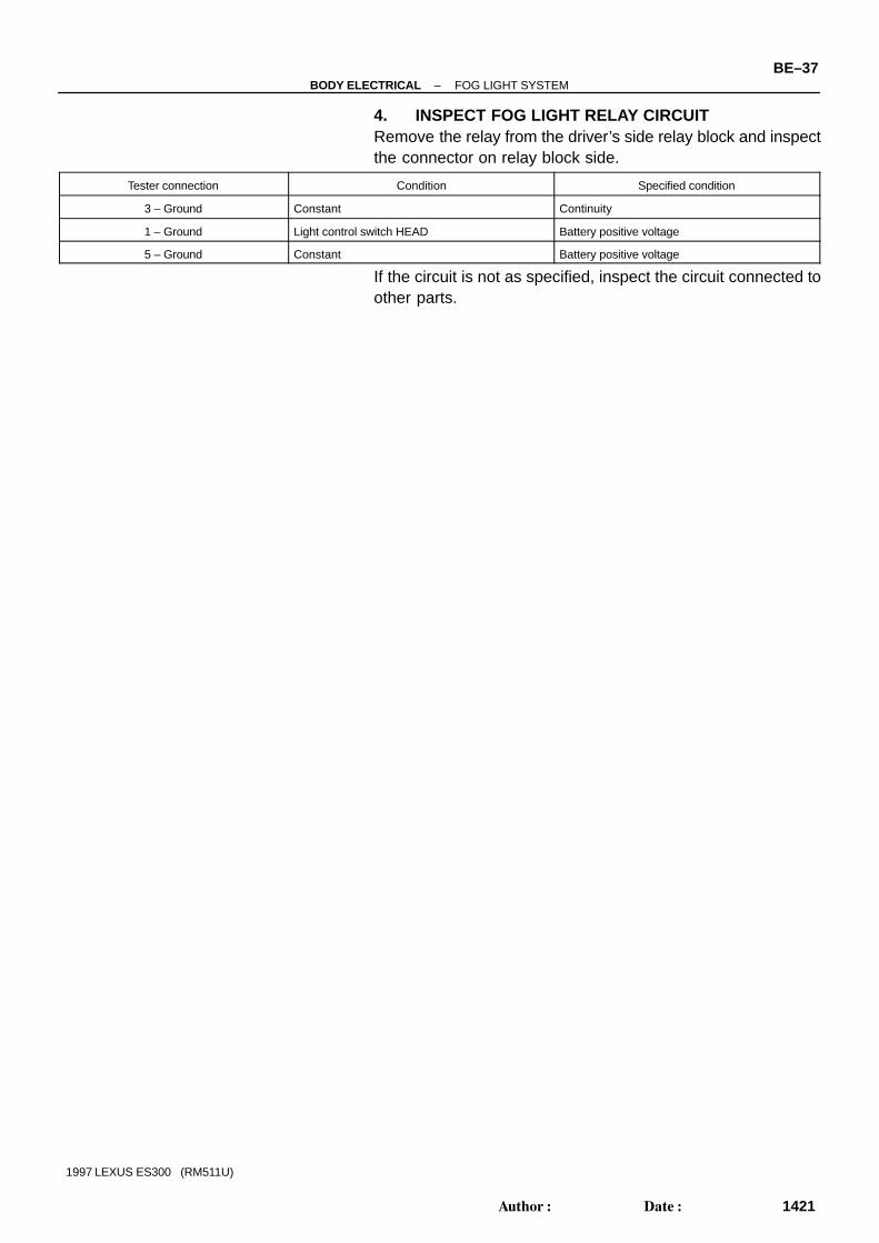
4. INSPECT FOG LIGHT RELAY CIRCUITRemove the relay from the driver’s side relay block and inspectthe connector on relay block side.
Tester connection Condition Specified condition
3 – Ground Constant Continuity
1 – Ground Light control switch HEAD Battery positive voltage
5 – Ground Constant Battery positive voltage
If the circuit is not as specified, inspect the circuit connected toother parts.

BE052–01
N21573
BE–38–BODY ELECTRICAL FOG LIGHT SYSTEM
1422Author: Date:
1997 LEXUS ES300 (RM511U)
ADJUSTMENTADJUST FOG LIGHT AIMA–bolt: Vertical Direction
Z19394
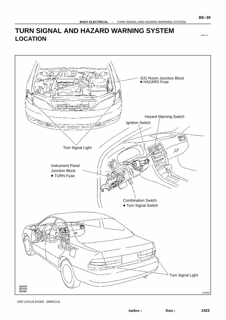
E/G Room Junction Block HAZARD Fuse
Hazard Warning Switch
Ignition Switch
Combination Switch Turn Signal Switch
Tum Signal Light
Instrument PanelJunction Block TURN Fuse
Tum Signal Light
BE053–01
–BODY ELECTRICAL TURN SIGNAL AND HAZARD WARNING SYSTEMBE–39
1423Author: Date:
1997 LEXUS ES300 (RM511U)
TURN SIGNAL AND HAZARD WARNING SYSTEMLOCATION

BE054–01
N21576
Right
Left
3 2 1
N21563
Wire Harness Side
1 2 3 4 5 6 7 8
9 10 11 1312 14 15 16 17
BE–40–BODY ELECTRICAL TURN SIGNAL AND HAZARD WARNING SYSTEM
1424Author: Date:
1997 LEXUS ES300 (RM511U)
INSPECTION1. INSPECT TURN SIGNAL SWITCH CONTINUITY
Switch position Tester connection Specified condition
Left turn 1 – 2 Continuity
Neutral – No continuity
Right turn 2 – 3 Continuity
If continuity is not as specified, replace the switch.
2. INSPECT COMBINATION SWITCH CIRCUITConnect the wire harness side connector to the combinationswitch and inspect wire harness side connector from the backside.
Tester connection Condition Specified condition
1 – Ground Constant *Continuity
3 – Ground Constant *Continuity
2 – GroundIgnition switch ON and turn signal switch position
NeutralNo voltage
2 – Ground Hazard warning switch ON Battery positive voltage
2 – GroundIgnition switch ON and turn signal switch position
Left or RightBattery positive voltage
*There is resistance because this circuit is grounded throughthe bulb.If the circuit is not as specified, inspect the circuit connected toother parts.

BE1843Turn Signal Light Bulbs(21W)
1
223
N21578e–10–2
1234
5678910
N21579e–10–1
1 2 3 4
5 6 7 8 9 10
Wire Harness Side
–BODY ELECTRICAL TURN SIGNAL AND HAZARD WARNING SYSTEMBE–41
1425Author: Date:
1997 LEXUS ES300 (RM511U)
3. INSPECT TURN SIGNAL FLASHER OPERATION(a) Connect the positive (+) lead from the battery to terminal
2 and the negative (–) lead to terminal 3.(b) Connect the 2 turn signal light bulbs in parallel to each
other to terminals 1 and 3, check that the bulbs flash.HINT:The turn signal lights should flash 60 to 120 times per minute.If one of the front or rear turn signal lights has an open circuit,the number of flashes will be more than 140 per minute.If operation is not as specified, replace the flasher.4. INSPECT HAZARD WARNING SWITCH CONTINUITY
Switch position Tester connection Specified condition
Switch OFF 5 – 7 Continuity
Switch ON1 – 2 – 3 – 4
5 – 6Continuity
Illumination circuit 8 – 9 Continuity
If continuity is not as specified, replace the switch.
5. INSPECT HAZARD WARNING SWITCH CIRCUITDisconnect the switch connector and inspect the connection onthe wire harness side.
Tester connection Condition Specified condition
1 – Ground Constant *2Continuity
2 – Ground Constant *2Continuity
*19 – Ground Constant Continuity
6 – Ground Constant Battery positive voltage
7 – Ground Ignition switch position LOCK or ACC No voltage
7 – Ground Ignition switch position ON Battery positive voltage
*18 – Ground Light control switch position OFF No voltage
*18 – Ground Light control switch position TAIL or HEAD Battery positive voltage
*1: Illumination*2: There is resistance because this circuit is grounded throughthe bulb.If the circuit is not as specified, inspect the circuits connectedto other parts.

N21591
Rheostat LightControl Volume
Glove BoxLIght Switch
BE055–01
BE–42–BODY ELECTRICAL ILLUMINATION LIGHT SYSTEM
1426Author: Date:
1997 LEXUS ES300 (RM511U)
ILLUMINATION LIGHT SYSTEMLOCATION

BE056–01
N21592
135
N21593
1257
N21594
7 6
Z08889
OFF
ON
2 1
–BODY ELECTRICAL ILLUMINATION LIGHT SYSTEMBE–43
1427Author: Date:
1997 LEXUS ES300 (RM511U)
INSPECTION1. Combination Meter Adjustment:
INSPECT RHEOSTAT LIGHT CONTROL VOLUME(a) Connect the positive (+) lead from the battery to terminal
5 and the negative (–) lead to terminal 1.(b) Connect the positive (+) lead from the voltmeter to termi-
nal 5 and negative (–) lead to terminal 3.(c) Turn the rheostat knob and check that the voltage
changes.
2. Illumination Adjustment:INSPECT RHEOSTAT LIGHT CONTROL VOLUME
(a) Connect the positive (+) lead from the battery to terminal5 and 7 and negative (–) lead to terminal 1.
(b) Connect the positive (+) lead from the voltmeter to termi-nal 7 and negative (–) lead to terminal 2.
(c) Turn the rheostat knob and check that the voltagechanges.
3. Tail Cancel:INSPECT RHEOSTAT LIGHT CONTROL VOLUME
(a) Connect the ohmmeter to terminals 6 and 7.(b) Turn the rheostat knob fully clockwise and check that cur-
rent flow stops.If switch is not as specified, replace the volume.
4. INSPECT GLOVE BOX LIGHT SWITCH CONTINUITY
Switch position Tester connection Specified condition
OFF (Closed) – No continuity
ON (Opened) 1 – 2 Continuity
If continuity is not as specified, replace the relay.

BE5710
Wire Harness Side
1 2
BE–44–BODY ELECTRICAL ILLUMINATION LIGHT SYSTEM
1428Author: Date:
1997 LEXUS ES300 (RM511U)
5. INSPECT GLOVE BOX LIGHT SWITCH CIRCUITDisconnect the connector fromt the switch and inspect the con-nector on the wire harness side.
Tester connection Condition Specified condition
2 – Ground Constant Continuity
1 – Ground Light control switch position OFF No voltage
1 – Ground Light control switch position TAIL or HEAD Battery positive voltage
If the circuit is not as specified, inspect the circuits connectedto other parts.

Z19395
E/G Room Junction Block DOME Fuse
Door Courtesy Switch
Instrument PanelJunction Block Integration Relay
Personal Light
Vanity Light Vanity Light
Door Courtesy Switch
Courtesy Light
Courtesy Light
Luggage CompartmentLight
Luggage CompartmentDoor Courtesy Switchand Opener Motor
BE057–01
–BODY ELECTRICAL INTERIOR LIGHT SYSTEMBE–45
1429Author: Date:
1997 LEXUS ES300 (RM511U)
INTERIOR LIGHT SYSTEMLOCATION

BE058–03
N21585
2 1
N21586
Wire Harness Side
1 2
Z05874
1
2
Z05672
Wire Harness Side
12
GA–2–1–B
BE–46–BODY ELECTRICAL INTERIOR LIGHT SYSTEM
1430Author: Date:
1997 LEXUS ES300 (RM511U)
INSPECTION1. INSPECT PERSONAL LIGHT SWITCH CONTINUITY
Switch position Tester connection Specified condition
OFF – No continuity
ON 1 – 2 Continuity
If continuity is not as specified, replace the light assembly orbulb.
2. INSPECT PERSONAL LIGHT SWITCH CIRCUITDisconnect the connector from the switch and inspect the con-nector on the wire harness side.
Tester connection Condition Specified condition
2 – Ground Constant Continuity
1 – Ground Constant Battery positive voltage
If the circuit is as specified, inspect power source or wire har-ness.
3. INSPECT INTERIOR LIGHT SWITCH CONTINUITY
Switch position Tester connection Specified condition
DOOR 2 – Switch body Continuity
OFF – No continuity
ON 1 – 2 Continuity
If continuity is not as specified, replace the light assembly orbulb.
4. INSPECT INTERIOR LIGHT SWITCH CIRCUITDisconnect the connector from the switch and inspect the con-nector on the wire harness side.

N17456
ON
OFF
2 1
N21587
Wire Harness Side
1 2
h–2–1–B
N20159
ON
OFF
Ohmmeter
–BODY ELECTRICAL INTERIOR LIGHT SYSTEMBE–47
1431Author: Date:
1997 LEXUS ES300 (RM511U)
Tester connection Condition Specified condition
2 – Ground Constant Battery positive voltage
If the circuit is not as specified, inspect power source or wireharness.
5. INSPECT VANITY LIGHT CONTINUITY
Switch position Tester connection Specified condition
OFF (Closed) – No continuity
ON (Opened) 1 – 2 Continuity
If continuity is not as specified, replace the bulb or vanity light.
6. INSPECT VANITY LIGHT SWITCH CIRCUITDisconnect the connector from the switch and inspect the con-nector on the wire harness side.
Tester connection Condition Specified condition
2 – Ground Constant Continuity
1 – Ground Constant Battery positive voltage
If the circuit is not as specified, inspect power source or wireharness.
7. INSPECT DOOR COURTESY SWITCH CONTINUITY(a) Check that continuity exists between terminals and the
switch body with the switch ON (switch pin released:opened door).
(b) Check that no continuity exists between terminals and theswitch body with the switch OFF (switch pin pushed in:closed doors).
If operation is not as specified, replace the switch.

N21588
1
Wire Harness Side
e–1–1
N21589
12
N21589
2 1
N21590
Wire Harness Side
e–2–1
1 2
BE–48–BODY ELECTRICAL INTERIOR LIGHT SYSTEM
1432Author: Date:
1997 LEXUS ES300 (RM511U)
8. INSPECT DOOR COURTESY SWITCH CIRCUITDisconnect the connector from the switch and inspect the con-nector on the wire harness side.
Tester connection Condition Specified condition
1 – Ground Constant Battery positive voltage
If the circuit is not as specified, inspect power source or wireharness.
9. INSPECT LUGGAGE COMPARTMENT DOOR COUR-TESY SWITCH CONTINUITY
Switch position Tester connection Specified condition
Switch OFF – No continuity
Switch ON 2 – Body Ground Continuity
If continuity is not as specified, replace the switch and motor.
10. INSPECT LUGGAGE COMPARTMENT DOOR OPEN-ER MOTOR OPERATION
Connect the positive (+) lead from the battery to terminal 1 andthe negative (–) lead to body ground, check that the motor oper-ates.If operation is not as specified, replace the switch and motor.
11. INSPECT LUGGAGE COMPARTMENT DOOR COUR-TESY SWITCH AND OPENER MOTOR CIRCUIT
Disconnect the connector from the switch and opener motor,and inspect the connector on the wire harness side.

–BODY ELECTRICAL INTERIOR LIGHT SYSTEMBE–49
1433Author: Date:
1997 LEXUS ES300 (RM511U)
Tester connection Condition Specified condition
1 – Ground Luggage compartment door opener switch OFF No voltage
1 – Ground Luggage compartment door opener switch ON Battery positive voltage
2 – Ground Constant Battery positive voltage
If the circuit is not as specified, inspect power source or wireharness.12. INSPECT ILLUMINATED ENTRY SYSTEM
(See integration relay circuit on page BE–20)

Z19396
Stop Light Switch
Instrument Panel Junction Block STOP Fuse
High–Mounted Stop Light
Light Failure Sensor
Stop Light
BE059–01
BE–50–BODY ELECTRICAL STOP LIGHT SYSTEM
1434Author: Date:
1997 LEXUS ES300 (RM511U)
STOP LIGHT SYSTEMLOCATION

BE05A–01
Z06565
12
34
4
2 1
3
Z06566
Wire Harness Side
1 2
3 4
eg–4–1
N21597
1 2
–BODY ELECTRICAL STOP LIGHT SYSTEMBE–51
1435Author: Date:
1997 LEXUS ES300 (RM511U)
INSPECTION1. INSPECT STOP LIGHT SWITCH CONTINUITY
Switch position Tester connection Specified condition
Switch pin free 1 – 2 Continuity
Switch pin pushed in 3 – 4 Continuity
If continuity is not as specified, replace the switch.
2. INSPECT STOP LIGHT SWITCH CIRCUITDisconnect the connector from the switch and inspect the con-nector on the wire harness side.
Tester connection Condition Specified condition
2 – Ground Constant Battery positive voltage
If circuit is not as specified, inspect the power source or wireharness.
3. INSPECT HIGH–MOUNTED STOP LIGHT ASSEMBLYCONTINUITY
Using the ohmmeter, check that continuity exists between ter-minals.If continuity is not as specified, replace the bulb or light assem-bly.

N21598
Wire Harness Side
1 2
e–2–1–J
N20209
Wire Harness Side
12345
6789101112
e–12–2–B
BE–52–BODY ELECTRICAL STOP LIGHT SYSTEM
1436Author: Date:
1997 LEXUS ES300 (RM511U)
4. INSPECT HIGH–MOUNTED STOP LIGHT ASSEMBLYCIRCUIT
Disconnect the connector from the switch and inspect the con-nector on the wire harness side.
Tester connection Condition Specified condition
1 – Ground Constant Battery positive voltage
If circuit is not as specified, inspect the power source or wireharness.
5. INSPECT LIGHT FAILURE SENSOR CIRCUITDisconnect the connector from the sensor and inspect the con-nector on the wire harness side.
Tester connection Condition Specified condition
1 – Ground Constant Continuity*
2 – Ground Constant Continuity*
9 – Ground Constant Continuity*
11 – Ground Constant Continuity
3 – Ground Light control switch OFF No voltage
3 – Ground Light control switch TAIL or HEAD Battery positive voltage
4 – Ground Ignition switch LOCK or ACC No voltage
4 – Ground Ignition switch ON Battery positive voltage
7 – Ground Stop light switch OFF No voltage
7 – Ground Stop light switch ON Battery positive voltage
8 – Ground Ignition switch LOCK or ACC No voltage
8 – Ground Ignition switch ON Battery positive voltage
*: There is resistance because this circuit is grounded throughthe bulb.If the circuit is as specified, replace the sensor.If the circuit is not as specified, inspect the circuits connectedto other parts.

Z19354
Wiper Motor
Washer Motor
Combination Switch Wiper and WasherSwitch
Ignition Switch
Instrument Panel Junction Block WIPER Fuse
BE05B–01
–BODY ELECTRICAL WIPER AND WASHER SYSTEMBE–53
1437Author: Date:
1997 LEXUS ES300 (RM511U)
WIPER AND WASHER SYSTEMLOCATION

BE05C–03
N21362
OFF
INTLO
HI
2
Washer ON
78
111617
N20210
27
16
N20211
27
17
16
INT time controlswitch position
FAST
SLOW
Non variable type
Voltage
Approx. 2 sec.
Battery positive voltage
0 V
Battery positive voltage
0 V
Battery positive voltage
0 V
10.7 ± 5 sec.
3.3 ± 1 sec.
BE–54–BODY ELECTRICAL WIPER AND WASHER SYSTEM
1438Author: Date:
1997 LEXUS ES300 (RM511U)
INSPECTION1. INSPECT FRONT WIPER AND WASHER SWITCH
CONTINUITY
Switch position Tester connection Specified condition
OFF 7 – 16 Continuity
INT 7 – 16 Continuity
LO 7 – 17 Continuity
HI 8 – 17 Continuity
Washer ON 2 – 11 Continuity
If continuity is not as specified, replace the switch.
2. INSPECT INTERMITTENT OPERATION(a) Turn the wiper switch to INT position.(b) Turn the intermittent time control switch to FAST position.(c) Connect the positive (+) lead from the battery to terminal
16 and the negative (–) lead to terminal 2.(d) Connect the positive (+) lead from the voltmeter to termi-
nal 7 and the negative (–) lead to terminal 2, check thatthe meter needle indicates battery positive voltage.
(e) After connecting terminal 16 to terminal 17, connect it toterminal 2, check the voltage rises from 0 volt to batterypositive voltage within the time, as shown in the table.
If operation is not as specified, replace the wiper and washerswitch.

N20210
16
7 2
N11301
Washer Switch ON
OFF
Battery Voltage
0 V
Less than 1 sec. Approx. 3 sec.
N21363
Wire Harness Side
1 2 3 4 5 6 7 8 9
10 11 12 13 14 15 16 17 18
N21364
1
5
–BODY ELECTRICAL WIPER AND WASHER SYSTEMBE–55
1439Author: Date:
1997 LEXUS ES300 (RM511U)
3. INSPECT WASHER LINKED OPERATION(a) Connect the positive (+) lead from the battery to terminal
16 and the negative (–) lead to terminal 2.(b) Connect the positive (+) lead from the voltmeter to termi-
nal 7 and the negative (–) lead to terminal 2.(c) Push in the washer switch, and check that the voltage
changes as shown in the table below.
If operation is not as specified, replace the wiper and washerswitch.
4. INSPECT WIPER SWITCH CIRCUITDisconnect the connector from the switch and inspect the con-nector on the wire harness side, as shown.
Tester connection Condition Specified condition
2 – Ground Constant Continuity
11 – Ground Ignition switch LOCK or ACC No voltage
11 – Ground Ignition switch ON Battery positive voltage
If circuit is not as specified, inspect the circuits connected to oth-er parts.
5. Low Speed:INSPECT FRONT WIPER MOTOR OPERATION
Connect the positive (+) lead from the battery to terminal 1 andthe negative (–) lead to terminal 5, check that the motor oper-ates at low speed.If operation is not as specified, replace the motor.

N21365
5 4
N21366
1
5
N21367
3
5
1
2
Z10066
Wire Harness Side
1 2 3
4 5
BE–56–BODY ELECTRICAL WIPER AND WASHER SYSTEM
1440Author: Date:
1997 LEXUS ES300 (RM511U)
6. High Speed:INSPECT FRONT WIPER MOTOR OPERATION
Connect the positive (+) lead from the battery to terminal 4 andthe negative (–) lead to terminal 5, check that the motor oper-ates at high speed.If operation is not as specified, replace the motor.
7. Stopping at Stop Position:INSPECT FRONT WIPER MOTOR OPERATION
(a) Operate the motor at low speed and stop the motor opera-tion anywhere except at the stop position by disconnect-ing positive (+) lead from terminal 1.
(b) Connect terminals 1 and 3.(c) Connect the positive (+) lead from the battery to terminal
2 and negative (–) lead to terminal 5, check that the motorstops running at the stop position after the motor operatesagain.
If operation is not as specified, replace the motor.
8. INSPECT WIPER MOTOR CIRCUITDisconnect the connector from the motor and inspect the con-nector on the wire harness side.
Tester connection Condition Specified condition
5 – Ground Constant Continuity
1 – Ground * Wiper switch OFF or INT, HIGH No voltage
1 – Ground * Wiper switch LOW Battery positive voltage
2 – Ground Ignition switch LOCK or ACC No voltage
2 – Ground Ignition switch ON Battery positive voltage
4 – Ground * Wiper switch OFF or INT, LOW No voltage
4 – Ground * Wiper switch HIGH Battery positive voltage

N21368
2
1
Z07418
Wire Harness Side
1
le–3–1–C
2 3
–BODY ELECTRICAL WIPER AND WASHER SYSTEMBE–57
1441Author: Date:
1997 LEXUS ES300 (RM511U)
*: Turn ignition switch ONIf circuit is not as specified, inspect the circuits connected to oth-er parts.
9. INSPECT WASHER MOTOR OPERATIONConnect the positive (+) lead from the battery to terminal 2 andthe negative (–) lead to terminal 1, check that the motor oper-ates.NOTICE:These tests must be performed quickly (within 20 seconds)to prevent the coil from burning out.If operation is not as specified, replace the motor.
10. INSPECT WASHER MOTOR CIRCUITDisconnect the connector from the washer motor and inspectthe connector on harness side.
Tester connection Condition Specified condition
1 – Ground Washer switch OFF (released) No continuity
1 – Ground Washer switch ON (pushed in) Continuity
2 – Ground Ignition switch LOCK or ACC No voltage
2 – Ground Ignition switch ON Battery positive voltage
If circuit is not as specified, inspect wire harness, power sourceor wiper switch.

BE05D–03
BE–58–BODY ELECTRICAL COMBINATION METER
1442Author: Date:
1997 LEXUS ES300 (RM511U)
COMBINATION METERTROUBLESHOOTINGPRECAUTIONS(a) When checking voltage, resistance, etc., use a high impedance type tester (It is impossible to use a
simple tester).(b) When the ignition switch is turned to START, all meters will go out but this is normal.(c) When replacing the internal mechanism (computer parts) of the meter, be careful that no part of your
body or clothing comes in contact with the terminals of the leads from the IC, etc. of the replacementparts (spare parts).
(d) Do not disconnect the battery while the engine is running as this would cause an instant reversecharge, resulting in damage to the components.
(e) Always disconnect the battery terminals before pulling apart connectors or terminals.(f) To prevent damage, handle meters with care.
Trouble Refer to
No display at all. 1
The four indicator needles do not light up.
Replace com-
bination meter
computer.
One indicator needle does not light up. 2
The character plate is not illuminated at one or two loca-
tions.3
All Meters, Gauges, and Illuminations Brightness does not change even when light control
switch is operated (OFF↔TAIL).4
Brightness does not change even when rheostat volume
is turned.5
Remains dimmed when the light control switch is turned
OFF.
Replace com-
bination meter
computer.
Does not go out while starter running. 6
S d tSpeedometer does not operate while driving. 7
SpeedometerVehicle speed signal (4P) faulty. 8
Tachometer Tachometer does not operate while engine running. 9
Fuel Gauge Does not operate or operation is abnormal. 10
Fuel Level Warning Warning light does not light up or always lights up. 11
Engine Coolant Temperature Gauge Does not operate or operation is abnormal. 12
Low Oil Pressure warning Abnormal operation or warning light does not light up. 13
Brake Warning Abnormal operation or warning light does not light up. 14
Rear Lights Warning Abnormal operation or warning light does not light up. 15
Open Door Warning Abnormal operation or warning light does not light up. 16
Engine Oil Level Warning Abnormal operation or warning light does not light up. 17
Seat Belt Warning Chime Abnormal operation or chime does not operate. BE–92
Seat Belt Warning Abnormal operation or warning light does not light up. 18

–BODY ELECTRICAL COMBINATION METERBE–59
1443Author: Date:
1997 LEXUS ES300 (RM511U)
Trouble Refer to
Turn Signal Indicator Abnormal operation or Indicator does not light up. 19
O/D OFF Indicator Abnormal operation or Indicator does not light up. 20
Shift Position Indicator Abnormal operation or Indicator does not light up. 21
Malfunction Indicator Abnormal operation or warning light does not light up 22
ABS Warning Abnormal operation or warning light does not light up. 23
CRUISE Indicator Abnormal operation or Indicator does not light up. 24
SRS Warning Abnormal operation or warning light does not light up. 25
Discharge Warning Abnormal operation or warning light does not light up. 26
High Beam Indicator Abnormal operation or Indicator does not light up. 27
Window Washer Warning Abnormal operation or warning light does not light up. 28
Taillight Indicator Abnormal operation or Indicator does not light up. 29
Headlight Indicator Abnormal operation or Indicator does not light up. 30

V08429
1 ALL METERS, GAUGES, ANDILLUMINATIONS No display at all.
INSPECT GROUND CIRCUIT
INSPECT POWER SOURCE
HINT : While carrying out the following inspection, make certain that the connectors and terminals are properly con-nected.
Turn ignition switch ON.Do warning lights light up? Is GAUGE fuse normal?
Open circuit in wire harnessbetween GAUGE fuse andcombination meter.
GAUGE fuse faulty.
Short circuit in wire harness on vehicle side.
Disconnect connector ”B” frommeter.Inspect connector on wireharness side as follows.
Replace GAUGE fuse and turnignition switch ON.Is fuse normal?
Disconnect connectors frommeter and replace GAUGE fuse.Then turn ignition switch ON.Is fuse normal?
Replace circuit plate.Then recheck system.
Is there continuity (no resistance) between terminalB15 and ground?
COMBINATIONMETER
No
Yes
Yes
Yes
Yes No
Yes
Yes
Yes
No
No
No
NoTurn ignition switch ON . Is there battery positive voltage between terminals D3 and B15?
Open circuit in wire harness between terminalof meter and ground. Ground faulty.
Open circuit in wire harness between terminal D3 ofmeter and GAUGE fuse.
Replace circuit plate. Then recheck system.
BE–60–BODY ELECTRICAL COMBINATION METER
1444Author: Date:
1997 LEXUS ES300 (RM511U)

V08430
ALL METERS, GAUGES, ANDILLUMINATIONS
ALL METERS, GAUGES, ANDILLUMINATIONS
One indicator needle does not light up.
The character plate is illuminated on one side.
INSPECT GROUND CIRCUIT
INSPECT POWER SOURCE
INSPECT GROUND CIRCUIT
HINT : While carrying out the following inspection, make certain that the connectors and terminals are properly con-nected.
Disconnect connector ”B” from meter.Inspect connector on wire harness side as follows.
Is there continuity (no resistance) between terminalB15 and ground?
Turn ignition switch ON . Is there battery positive voltage between terminals D3 and B15?
Open circuit in wire harness between terminalof meter and ground. Ground faulty.
Open circuit in wire harness between terminal D3 ofmeter and GAUGE fuse.
Replace circuit plate. Then recheck system.
HINT : While carrying out the following inspection, make certain that the connectors and terminals are properly con-nected.
Disconnect connector ”B” from meter.Inspect connector on wire harness side as follows.
Is there continuity (no resistance) between terminalB15 and ground?
Open circuit in wire harness between terminal D3of meter and ground. Ground faulty.
Replace circuit plate. Then recheck system.
Turn ignition switch ON . Is there battery positive voltage between terminals D3 and B15?
INSPECT POWER SOURCE
Yes
No
Yes
Yes
Yes
Yes
No
No
No
No
No
Yes
Is LED OK? Replace the LED.Then recheck system.
Replace the LED.Then recheck system.Is bulb OK?
Open circuit in wire harness between terminal D3 ofmeter and GAUGE fuse.
2
3
–BODY ELECTRICAL COMBINATION METERBE–61
1445Author: Date:
1997 LEXUS ES300 (RM511U)

V08431
ALL METERS, GAUGES, ANDILLUMINATIONS
ALL METERS, GAUGES, ANDILLUMINATIONS
HINT : While carrying out the following inspection, make certain that the connectors and terminals are properly con-nected.
Disconnect connector ”B” from meter.Inspect connector on wire harness side as follows.
Replace circuit plate. Then recheck system.
HINT : While carrying out the following inspection, make certain that the connectors and terminals are properly con-nected.
No
Yes
4
5
Brightness does not change evenwhen light control switch is operated.(OFF↔TAIL)
Brightness does not change even whenrheostat volume is turned.
RHEOSTAT LIGHTCONTROL VOLUME
COMBINATIONMETER
COMBINATIONMETER
Yes
No
Yes
No
INSPECT TAILLIGHT SIGNAL CIRCUIT
Does voltage change between terminal B8 andground as follows?
Taillight signal circuit faulty on vehicle side.Inspect illumination light system.
Battery positive voltage
Replace rheostat light control volume.Then recheck system.
Wire harness faulty between terminal D1 of meterand terminal D2 of rheostat volume and rheostatlight control.
Condition VoltageLight controlswitchposition
OFF No voltage
TAIL or HEAD
INSPECT RHEOSTAT LIGHT CONTROL VOLUME(See page BE–)
Is operation normal?
Connect connector to rheostat volume.Disconnect connector ”D” from meter.Inspect connector on wire harness side as follows.
Turn ignition switch ON. Does voltage changeevenly between terminal D1 and D2 when rheostatknob is turned?
Replace circuit plate. Then recheck system.
BE–62–BODY ELECTRICAL COMBINATION METER
1446Author: Date:
1997 LEXUS ES300 (RM511U)

V08432
ALL METERS, GAUGES, ANDILLUMINATIONS
HINT : While carrying out the following inspection, make certain that the connectors and terminals are properly con-nected.
Disconnect connector ”B” from meter.Inspect connector on wire harness side as follows.
Replace circuit plate. Then recheck system.
6
7 SPEEDOMETER
Does not go out while starter running.
Speedometer does not operate whiledriving
Replace circuit plate. Then recheck system.
No
Yes
COMBINATIONMETER
Yes
Yes
YesNo
No
No
Wire harness faulty between terminal B16 of Meterand ST fuse.
Turn ignition switch START.Is there battery positive voltage between terminal andground or B16?
Does odometer operate while driving? Does trip meter operate while driving?
CONTINUED ON NEXT PAGE
Jack up the vehicle.Turn ignition switch ON. Rotate propeller shaft.Does the voltage between terminals C9 and C10 change (approx. 0V to 11V or more) per revolution ofpropeller shaft?
Disconnect connector ”C” from meter.Inspect connector on wire harness side as follows.
HINT : While carrying out the following inspection, make certain that the connectors and terminals are properly con-nected.
INSPECT TRIP METER OPERATIONINSPECT ODOMETER OPERATION
Replace speedometer.Then recheck system. Go to step 7–A
–BODY ELECTRICAL COMBINATION METERBE–63
1447Author: Date:
1997 LEXUS ES300 (RM511U)

V08433
8 SPEEDOMETER
Replace circuit plate. Then recheck system.
COMBINATIONMETER
Yes
NoDoes odometer operate while driving?
Jack up the vehicle. Turn ignition switch ON.Rotate propeller shaft. Does the voltage betweenterminals C10 and ground change (approx. 0V to 5Vor more) per revolution of propeller shaft?
Disconnect connectors ”A” and ”C” from meter.Inspect connector on wire harness side as follows.
HINT : While carrying out the following inspection, make certain that the connectors and terminals are properly con-nected.
INSPECT ODOMETER OPERATIONSee chart 18.
ECM
HINT : While carrying out the following inspection, make certain that the connectors and terminals are properly con-nected.
Replace circuit plate. Then recheck system.
Remove meter with connector connected.Inspect connector ”C” from back side as follows.
Wire harness between terminal C10 of meter and*ECU faulty.
Power Steering ECU
* : An electrical tester availble to measure frrequency is necessary for this inspection. REFERENCE : TOYOTA ELECTRICAL TESTER (09082–00050)
Suspension ECU ABS and TRAC ECU
With engine running, does voltage between terminalsA13 and C10 fluctuate?
Cruise Control ECU
Yes
No
9
Vehicle speed signal (4P) faulty
Tachometer dose not operate whileengine running.TACHOMETER
Yes
No* INSPECT TACHOMETER CIRCUITWire harness faulty between terminal A13 of meterand igniter.
BE–64–BODY ELECTRICAL COMBINATION METER
1448Author: Date:
1997 LEXUS ES300 (RM511U)

V08434
COMBINATION METER
Yes
No
Disconnect connector ”D” from meter.Inspect connector on wire harness side as follows.
HINT : While carrying out the following inspection, make certain that the connectors and terminals are properly con-nected.
Yes
Yes
Yes
No
No
No
Is operation normal?
Replace receiver gauge. Then recheck system.
Is there continuity (no resistance ) between terminalD12 and ground?
Are speedometer and tachometer operating normally?
Replace combinationmeter computer.Then recheck system.
Open circuit in wireharness between terminal 12 of meter and ground. Ground faulty.
Wire harness faulty between meter and sender gauge.
Replace sender gauge. Then recheck system.
Is operation normal?
Is resistance normal?
Replace combination meter computer.Then recheck system.
INSPECT SENDER GAUGE OPERATION(See page BE–92)
INSPECT RECEIVER GAUGE RESISTANCE(See page BE–92)
INSPECT RECEIVER GAUGE OPERATION(See page BE–92)
FUEL GAUGEDoes not operate or operation isabnormal.10
Yes No
–BODY ELECTRICAL COMBINATION METERBE–65
1449Author: Date:
1997 LEXUS ES300 (RM511U)

V08435
Disconnect connector ”D” from meter.Inspect connector on combination meter side asfollows.
HINT : While carrying out the following inspection, make certain that the connectors and terminals are properly con-nected.
Yes
Replace combinationmeter computer.Then recheck system.
Yes
Yes
Yes
No No
No
No
Yes
Is bulb OK?
INSPECT FUEL LEVEL WARNING LIGHT(See page BE–92)
Replace bulb.Then recheck system.
Ground terminal D11 and turn ignition switch ON.Does fuel level warning light up?
Replace circuit plate.
If operation is not as specified, replace the switch.Then recheck system.
Wire harness faulty between terminal D11 ofmeter and terminal 1 of sender gauge.
Temporarily install another circuit plate.Is operation normal?
INSPECT FUEL LEVEL WARNING SWITCH(See page BE–92)
11 FUEL LEVEL WARNINGWarning light does not light up or alwayslights up.
Is operation normal?
BE–66–BODY ELECTRICAL COMBINATION METER
1450Author: Date:
1997 LEXUS ES300 (RM511U)

V08436
Disconnect connector ”A” from meter.Inspect connector on wire harness side.
HINT : While carrying out the following inspection, make certain that the connectors and terminals are properly con-nected.
Yes
No
Wire harness faulty between terminal A1 of meterand ground.
No
No
No
No
Yes
Yes
INSPECT RECEIVER GAUGE OPERATION(See page BE–92)
Yes
Yes
INSPECT RECEIVER GAUGE RESISTANCE(See page BE–92)
Wire harness faulty between terminal A3 of meterand sender gauge.
Sender gauge ground condition faulty.
Replace sender gauge. Then recheck system.
INSPECT SENDER GAUGE GROUND CONDITIONIs there continuity (no resistance) between gaugebody and engine block?
Is resistance normal?
Is there continuity between terminal A3 and ground?
Replace receiver gauge. Then recheck system.
Is there continuity between terminal A1 and ground?
Replace combination meter computer.Then recheck system.
COMBINATIONMETER
12 ENGINE COOLANT TEMPERATUREGAUGE
Does not operate or operation isabnormal.
Is operation normal?
–BODY ELECTRICAL COMBINATION METERBE–67
1451Author: Date:
1997 LEXUS ES300 (RM511U)
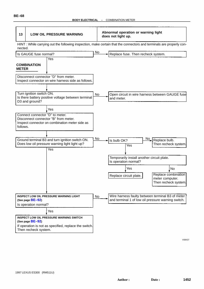
V08437
Disconnect connector ”D” from meter.Inspect connector on wire harness side as follows.
HINT : While carrying out the following inspection, make certain that the connectors and terminals are properly con-nected.
Yes
Wire harness faulty between terminal B3 of meterand terminal 1 of low oil pressure warning switch.
No
COMBINATIONMETER
13 LOW OIL PRESSURE WARNING Abnormal operation or warning lightdoes not light up.
Is GAUGE fuse normal? Replace fuse. Then recheck system.
Open circuit in wire harness between GAUGE fuseand meter.
Connect connector ”D” to meter.Disconnect connector ”B” from meter.Inspect connector on combination meter side asfollows.
Ground terminal B3 and turn ignition switch ON.Does low oil pressure warning light light up?
Temporarily install another circuit plate.Is operation normal?
Turn ignition switch ON.Is there battery positive voltage between terminalD3 and ground?
Is bulb OK? Replace bulb.Then recheck system.
Replace circuit plate. Replace combinationmeter computer.Then recheck system.
INSPECT LOW OIL PRESSURE WARNING LIGHT(See page BE–92)
INSPECT LOW OIL PRESSURE WARNING SWITCH(See page BE–92)
No
No No
No
No
Yes
YesYes
Yes
Yes
If operation is not as specified, replace the switch.Then recheck system.
Is operation normal?
BE–68–BODY ELECTRICAL COMBINATION METER
1452Author: Date:
1997 LEXUS ES300 (RM511U)

V08438
Disconnect connector ”D” from meter.Inspect connector on wire harness side as follows.
HINT : While carrying out the following inspection, make certain that the connectors and terminals are properly con-nected.
Yes
Wire harness faulty between terminal A9 of meter and1 Terminal 1 of parking brake switch.2 Terminal 1 of brake fluid level warning switch.
No
COMBINATIONMETER
Abnormal operation or warning lightdoes not light up.
Is GAUGE fuse normal? Replace fuse. Then recheck system.
Open circuit in wire harness between GAUGE fuseand meter.
Connect connector ”D” to meter.Disconnect connector ”A” from meter.Inspect connector on combination meter side asfollows.
Ground terminal A9 and turn ignition switch ON.Does brake warning light light up?
Temporarily install another circuit plate.Is operation normal?
Turn ignition switch ON.Is there battery positive voltage between terminalD3 and ground?
Is bulb OK? Replace bulb.Then recheck system.
Replace circuit plate. Replace combinationmeter computer.Then recheck system.
INSPECT BRAKE WARNING LIGHT(See page BE–92)
INSPECT PARKING BRAKE SWITCH(See page BE–92)
No
No No
Yes
Yes
If operation is not as specified, replace the switch.Then recheck system.
Is operation normal?
INSPECT BRAKE FLUID LEVEL WARNING SWITCH(See page BE–92)
Is operation normal?
Yes
Yes
No
No
Yes
Yes No
14 BRAKE WARNING
Replace brake fluid level warning switch.Then recheck system.
–BODY ELECTRICAL COMBINATION METERBE–69
1453Author: Date:
1997 LEXUS ES300 (RM511U)

V08439
Disconnect connector ”D” from meter.Inspect connector on wire harness side as follows.
HINT : While carrying out the following inspection, make certain that the connectors and terminals are properly con-nected.
Yes
No
COMBINATIONMETER
Abnormal operation or warning lightdoes not light up.
Is GAUGE fuse normal? Replace fuse. Then recheck system.
Open circuit in wire harness between GAUGE fuseand meter.
Connect connector ”D” to meter.Disconnect connector ”A” from meter.Inspect connector on combination meter side asfollows.
Ground terminal A7 and turn ignition switch ON.Does light failure warning light light up?
Temporarily install another circuit plate.Is operation normal?
Turn ignition switch ON.Is there battery positive voltage between terminalD3 and ground?
Is bulb OK? Replace bulb.Then recheck system.
Replace circuit plate. Replace combinationmeter computer.Then recheck system.
INSPECT LIGHT FAILURE SENSOR CIRCUIT(See page BE–92)
No
No No
Yes
YesYes
Yes No
REAR LIGHTS WARNING15
If circuit is as specified, replace the sensor.Then recheck system.
BE–70–BODY ELECTRICAL COMBINATION METER
1454Author: Date:
1997 LEXUS ES300 (RM511U)

V08440
Disconnect connector ”C” from meter.Inspect connector on wire harness side as follows.
HINT : While carrying out the following inspection, make certain that the connectors and terminals are properly con-nected.
Yes
No
COMBINATIONMETER
Abnormal operation or warning lightdoes not light up.
Is DOME fuse normal? Replace fuse. Then recheck system.
Open circuit in wire harness between GAUGE fuseand meter.
Connect connector ”C” to meter.Disconnect connector ”C” from meter.Inspect connector on combination meter side asfollows.
Ground terminal C6. Does open door warning light light up?
Temporarily install another circuit plate.Is operation normal?
Is there battery positive voltage between terminalC6 and ground?
Is bulb OK? Replace bulb.Then recheck system.
Replace circuit plate. Replace combinationmeter computer.Then recheck system.
INSPECT OPEN DOOR WARNING LIGHT(See page BE–92)
No
No No
Yes
Yes
Yes
Yes No
If operation is not as specified, replace the switch.Then recheck system.
16 OPEN DOOR WARNING
Is operation normal?
INSPECT DOOR COURTESY SWITCH(See page BE–92)
Yes
No Wire harness faulty between terminal C6 of meterand terminal 1 of door courtesy switch.
–BODY ELECTRICAL COMBINATION METERBE–71
1455Author: Date:
1997 LEXUS ES300 (RM511U)

V08441
17
No Replace fuse. Then recheck system.
Open circuit in wire harness between GAUGE fuseand meter.
Temporarily install another circuit plate.Is operation normal?
Is bulb OK? Replace bulb.Then recheck system.
Replace circuit plate. Replace combinationmeter computer.Then recheck system.
No
No No
Yes
Yes No
No Wire harness faulty between terminal C7 of meterand terminal 1 of engine oil level warning switch.
Disconnect connector ”D” from meter.Inspect connector on wire harness side as follows.
HINT : While carrying out the following inspection, make certain that the connectors and terminals are properly con-nected.
Yes
COMBINATIONMETER
Is GAUGE fuse normal?
Connect connector ”D” to meter.Disconnect connector ”C” from meter.Turn ignition switch ON.Does engine oil level warning light light up afterapproximately 40 secs.?
Turn ignition switch ON.Is there battery positive voltage between terminalD3 and ground?
INSPECT ENGINE OIL LEVEL WARNING LIGHT(See page BE–92)
Yes
Yes
Is operation normal?
INSPECT ENGINE OIL LEVEL WARNING SWITCH(See page BE–92)
Yes
If operation is not as specified, replace the switch.Then recheck system.
ENGINE OIL LEVEL WARNINGAbnormal operation or warning lightdoes not light up.
BE–72–BODY ELECTRICAL COMBINATION METER
1456Author: Date:
1997 LEXUS ES300 (RM511U)
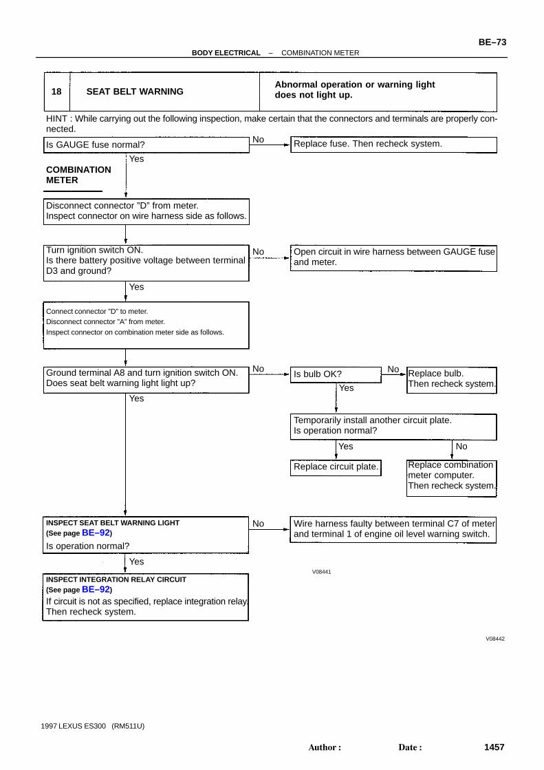
V08442
18
V08441
No Replace fuse. Then recheck system.
Open circuit in wire harness between GAUGE fuseand meter.
Temporarily install another circuit plate.Is operation normal?
Is bulb OK? Replace bulb.Then recheck system.
Replace circuit plate. Replace combinationmeter computer.Then recheck system.
No
No No
Yes
Yes No
No Wire harness faulty between terminal C7 of meterand terminal 1 of engine oil level warning switch.
Disconnect connector ”D” from meter.Inspect connector on wire harness side as follows.
HINT : While carrying out the following inspection, make certain that the connectors and terminals are properly con-nected.
YesCOMBINATIONMETER
Is GAUGE fuse normal?
Connect connector ”D” to meter.Disconnect connector ”A” from meter.Inspect connector on combination meter side as follows.
Turn ignition switch ON.Is there battery positive voltage between terminalD3 and ground?
INSPECT SEAT BELT WARNING LIGHT(See page BE–92)
Yes
Yes
Is operation normal?
INSPECT INTEGRATION RELAY CIRCUIT(See page BE–92)
Yes
If circuit is not as specified, replace integration relay.Then recheck system.
SEAT BELT WARNINGAbnormal operation or warning lightdoes not light up.
Ground terminal A8 and turn ignition switch ON.Does seat belt warning light light up?
–BODY ELECTRICAL COMBINATION METERBE–73
1457Author: Date:
1997 LEXUS ES300 (RM511U)

V08443
19
Is bulb OK? Replace the bulb. Then recheck system.
Disconnect connector ”D” from meter.Inspect connector on wire harness side as follows.
HINT : While carrying out the following inspection, make certain that the connectors and terminals are properly con-nected.
Turn ignition switch ON.Is there battery positive voltage between terminalsxx and ground with the turn signal lever to left andright?
Yes
Abnormal operation or warning lightdoes not light up.
Turn signal indicator signal circuit faulty.Inspect the turn signal and hazard warning lightsystem.
Replace circuit plate. Then recheck system.
Turn signal to
Terminal xx
Left
B11
Right
B13
No
TURN SIGNAL INDICATOR
Yes
No
20
Is bulb OK? Replace the bulb. Then recheck system.
Inspect connector on wire harness side as follows.
HINT : While carrying out the following inspection, make certain that the connectors and terminals are properly con-nected.
Ground terminal D6 and turn ignition switch ON.Does TRAC OFF indicator light up?
Yes
Abnormal operation or indicator doesnot light up.
Inspect the wire harness between terminal D6 ofmeter and ABS & TRAC ECU or inspect ABS &TRAC ECU.
Replace circuit plate. Then recheck system.
No
TRAC OFF INDICATOR
Yes
No
Replace power source unit.No
Yes
BE–74–BODY ELECTRICAL COMBINATION METER
1458Author: Date:
1997 LEXUS ES300 (RM511U)

V08444
Is bulb OK? Replace the bulb.
Disconnect connector ”B” from meter.Inspect connector on combination meter side asfollows.
HINT : While carrying out the following inspection, make certain that the connectors and terminals are properly con-nected.
Abnormal operation or indicator doesnot light up.
Replace circuit plate. Then recheck system.
Yes
No
Yes
No
21 O/D OFF INDICATOR
Ground terminal B5 and turn ignition switch ON.Does O/D OFF indicator light up?
O/D OFF indicator signal circuit faulty.
HINT : While carrying out the following inspection, make certain that the connectors and terminals are properly con-nected.
Disconnect connector ”D” from meter.Inspect connector on wire harness side as follows.
Is bulb OK?
Replace circuit plate. Then recheck system.
Replace the bulb. Then recheck system.
Shift position indicator signal circuit faulty.
22 SHIFT POSITION INDICATOR
Turn ignition switch ON.Is there battery positive voltage between terminalsXX and ground with turn shift lever to P through L
Shift to
Terminal XX
P
B12
R
B14
N
C1
D
C2
2
B10
L
B9
Abnormal operation or indicator doesnot light up.
Yes
Yes
No
No
–BODY ELECTRICAL COMBINATION METERBE–75
1459Author: Date:
1997 LEXUS ES300 (RM511U)

V08445
Is bulb OK?
Disconnect connector ”D” from meter.Inspect connector on wire harness side as follows.
HINT : While carrying out the following inspection, make certain that the connectors and terminals are properly con-nected.
Replace fuse. Then recheck system.No
Yes
23 MALFUNCTION WARNING
Ground terminal D5 and turn ignition switch ON.Does check engine warning light light up?
Replace the bulb.Then recheck system.
Turn ignition switch ON.Is there battery positive voltage between terminalD3 and ground?
Replace circuit plate. Replace combinationmeter computer.Then recheck system.
Temporarily install another circuit plate.Is operation normal?
Open circuit in wire harness between GAUGE fuseand meter.
Is GAUGE fuse normal?
Connect connector ”D” to meter.Disconnect connector ”D” from meter.Inspect connector on combination meter side asfollows.
Wire harness faulty between ECM and meter. ECM faulty.
Yes
Yes
Yes
No
No No
Yes
No
Abnormal operation or warning lightdoes not light up.
COMBINATIONMETER
BE–76–BODY ELECTRICAL COMBINATION METER
1460Author: Date:
1997 LEXUS ES300 (RM511U)

V08446
Is bulb OK?
Disconnect connector ”D” from meter.Inspect connector on wire harness side as follows.
HINT : While carrying out the following inspection, make certain that the connectors and terminals are properly con-nected.
Replace fuse. Then recheck system.No
Yes
Ground terminal D7 and turn ignition switch ON.Does ABS warning light light up?
Replace bulb.Then recheck system.
Turn ignition switch ON.Is there battery positive voltage between terminalD3 and ground?
Replace circuit plate. Replace combinationmeter computer.Then recheck system.
Temporarily install another circuit plate.Is operation normal?
Open circuit in wire harness between GAUGE fuseand meter.
Is GAUGE fuse normal?
Connect connector ”D” to meter.Disconnect connector ”D” from meter.Inspect connector on combination meter side asfollows.
Wire harness faulty between ABS ECU and meter. ABS ECU faulty.
Yes
Yes
No
NoNo
Yes
No
COMBINATIONMETER
24 ABS WARNINGAbnormal operation or warning lightdoes not light up.
–BODY ELECTRICAL COMBINATION METERBE–77
1461Author: Date:
1997 LEXUS ES300 (RM511U)

V08447
Is bulb OK?
Disconnect connector ”D” from meter.Inspect connector on wire harness side as follows.
HINT : While carrying out the following inspection, make certain that the connectors and terminals are properly con-nected.
Replace fuse. Then recheck system.No
Yes
Ground terminal A4 and turn ignition switch ON.Does CRUISE indicator light up?
Replace bulb.Then recheck system.
Turn ignition switch ON.Is there battery positive voltage between terminalD3 and ground?
Replace circuit plate. Replace combinationmeter computer.Then recheck system.
Temporarily install another circuit plate.Is operation normal?
Open circuit in wire harness between GAUGE fuseand meter.
Is GAUGE fuse normal?
Connect connector ”D” to meter.Disconnect connector ”A” from meter.Inspect connector on combination meter side asfollows.
Wire harness faulty between cruise control ECUand meter. Cruise control ECU faulty.
Yes
Yes
No
No No
Yes
No
COMBINATIONMETER
25 CRUISE INDICATOR Abnormal operation or indicatordoes not light up.
Yes
BE–78–BODY ELECTRICAL COMBINATION METER
1462Author: Date:
1997 LEXUS ES300 (RM511U)

V08448
Is bulb OK?
Disconnect connector ”D” from meter.Inspect connector on wire harness side as follows.
HINT : While carrying out the following inspection, make certain that the connectors and terminals are properly con-nected.
Replace fuse. Then recheck system.No
Yes
Replace bulb.Then recheck system.
Is there battery positive voltage between terminaland ground?
Replace circuit plate. Replace combinationmeter computer.Then recheck system.
Temporarily install another circuit plate.Is operation normal?
Open circuit in wire harness between ECU–B fuseand meter.
Is ECU–B fuse normal?
Wire harness faulty between center airbag sensor assembly and meter. Center airbag sensor assembly faulty.
Yes
No
No No
Yes
No
COMBINATIONMETER
26 SRS WARNING Abnormal operation or warning lightdoes not light up.
Yes
Inspect connector on meter side as follows.
Is there continuity between terminals D8 and D9 ofmeter?
Yes
–BODY ELECTRICAL COMBINATION METERBE–79
1463Author: Date:
1997 LEXUS ES300 (RM511U)

V08449
Is bulb OK?
Disconnect connector ”A” and ”B” from meter.Inspect connector on wire harness side as follows.
HINT : While carrying out the following inspection, make certain that the connectors and terminals are properly con-nected.
Replace fuse. Then recheck system.No
Yes
Replace bulb.Then recheck system.
Turn ignition switch ON.Is there battery positive voltage between terminaland ground?
Replace circuit plate. Replace combinationmeter computer.Then recheck system.
Temporarily install another circuit plate.Is operation normal?
Open circuit in wire harness between IGN fuseand meter.
Is IGN fuse normal?
Wire harness faulty between generator and meter.
Yes
No
No No
Yes
No
COMBINATIONMETER
27 DISCHARGE WARNINGAbnormal operation or warning lightdoes not light up.
Yes
Inspect connector on meter side as follows.
Yes
Yes
Connect negative (–) lead from tester to terminal A10and positive (+) lead to terminal B2 of meter.Is there continuity between terminals?
Connect connectors ”A” and ”B” to meter.Disconnect connector from generator.Does warning light light up?
Inspect generator.No
BE–80–BODY ELECTRICAL COMBINATION METER
1464Author: Date:
1997 LEXUS ES300 (RM511U)

V08450
Is bulb OK?
Disconnect connector ”C” from meter.Inspect connector on wire harness side as follows.
HINT : While carrying out the following inspection, make certain that the connectors and terminals are properly con-nected.
No
Yes
Replace bulb.Then recheck system.
Turn light control switch to HEAD and headlight dimmerswitch to HI.Is there battery positive voltage between terminal C5and ground?
Replace circuit plate. Replace combinationmeter computer.Then recheck system.
Temporarily install another circuit plate.Is operation normal?
Yes
No
Yes
No
COMBINATIONMETER
28 HIGH BEAM INDICATOR Abnormal operation or indicatordoes not light up.
Yes
Inspect connector on meter side as follows.
Yes
Turn headlight dimmer switch to FLASH.Does headlight high beam light up?
Inspect headlight and taillight system (BE–27).
Is there continuity between terminal C3 and C5 ofmeter?
Wire harness faulty between meter and: 1 (USA) headlight dimmer switch2 (CANADA) ground
Wire harness faulty between meter and: 1 (USA) HEAD (RH) fuse2 (CANADA) daytime running light relay No.3
No
No
–BODY ELECTRICAL COMBINATION METERBE–81
1465Author: Date:
1997 LEXUS ES300 (RM511U)

V08451
Disconnect connector ”D” from meter.Inspect connector on combination meter side asfollows.
HINT : While carrying out the following inspection, make certain that the connectors and terminals are properly con-nected.
Yes
29 WINDOW WASHER LEVELWARNING SWITCH
Abnormal operation or indicatordoes not light up.
No
Ground terminal D10 and turn ignition switch ON.Does washer level warning light light up?
Is bulb OK?
Is operation normal?
Replace the circuit plate.
Inspect alternator and wire harness between D10of meter and generator.
Replace the bulb. Then recheck system.
Replace the switch. Then recheck system.INSPECT WINDOW WASHER LEVELWARNING SWITCH (See page BE–92)
Yes
Yes
No
No
Disconnect connector ”B” from meter.Inspect connector on combination meter side.
HINT : While carrying out the following inspection, make certain that the connectors and terminals are properly con-nected.
Yes
30 SLIP INDICATOR Abnormal operation or indicator does notlight up.
No
Ground terminal B4 and turn ignition switch ON.Does SLIP indicator light light up?
Is bulb OK?
Replace the circuit plate.
Inspect the wire harness between terminal B4 ofmeter and ABS & TRAC ECU, or inspect ABS &TRAC ECU.
Replace the bulb. Then recheck system.
Replace power source unit.
Yes
Yes
No
BE–82–BODY ELECTRICAL COMBINATION METER
1466Author: Date:
1997 LEXUS ES300 (RM511U)

V08452
Disconnect connectors ”C” from meter.Inspect connector on wire harness side as follows.
HINT : While carrying out the following inspection, make certain that the connectors and terminals are properly con-nected.
Yes
31
Ground terminal B7 and turn the light controlswitch to TAIL. Does taillight indicator light up?
Is bulb OK?
Replace circuit plate.
No
Abnormal operation or indicatordoes not light up.TAILLIGHT INDICATOR
Turn the light control switch to TAIL.Does taillight light up?
Inspect headlight and taillight system.(See page BE–27).
Wire harness faulty between meter and: Light control switch. Taillight Relay, Panel Relay (CANADA)
Is there battery positive voltage (0 V ↔ batterypositive voltage) between following terminals withlight control switch TAIL? C5 and ground.
Connect connectors ”B” to meter.Disconnect connector ”B” from meter.Inspect connector on combination meter side asfollows.
Open circuit in wire harness between terminal B7 of meter and ground. Ground faulty.
Temporarily install another circuit plate.Is operation normal?
Replace bulb.Then recheck system.
Replace combinationmeter computer.Then recheck system.
No
Yes
YesYes
Yes
No No
No
COMBINATIONMETER
–BODY ELECTRICAL COMBINATION METERBE–83
1467Author: Date:
1997 LEXUS ES300 (RM511U)

V08453
Disconnect connector ”C” from meter.Inspect connector on wire harness side as follows.
HINT : While carrying out the following inspection, make certain that the connectors and terminals are properly con-nected.
Yes
32
Ground terminal B7 and turn light control switch toHEAD. Does headlight indicator light up?
Is bulb OK?
Replace circuit plate.
No
Abnormal operation or indicatordoes not light up.HEADLIGHT INDICATOR
Turn light control switch to HEAD.Do headlights light up?
Inspect headlight and taillight system.(See page BE–27).
Is there battery positive voltage (0 V ↔ batterypositive voltage) between following terminals withlight control switch HEAD? C5 and ground.
Connect connector ”A” to meter.Disconnect connector ”B” from meter.Inspect connector on combination meter side asfollows.
Open circuit in wire harness between terminal B7 of meter and ground. Ground faulty.
Temporarily install another circuit plate.Is operation normal?
Replace bulb.Then recheck system.
Replace combinationmeter computer.Then recheck system.
No
Yes
YesYes
Yes
No No
No
COMBINATIONMETER
Wire harness faulty between meter and: Light control switch HEAD Fuse Headlight control relay
BE–84–BODY ELECTRICAL COMBINATION METER
1468Author: Date:
1997 LEXUS ES300 (RM511U)

BE05E–01
Z18765
Engine RoomJunction Block DOME Fuse ECU–B Fuse HEAD (LH) Fuse HEAD (RH) Fuse
Engine Oil Level Sensor
Washer Level Warning Switch
Washer TankBrake Fluid LevelWaming Switch
ECM
ABS ECU orABS and Traction ECU
O/D OFF Switch
Combination Meter Meter Circuit Bulb Check Relay
Light ControlRheostat
Instrument PanelJunction Block GAUGE Fuse IGN Fuse
Seat Belt Buckle SwitchAirbag Sensor Assembly
–BODY ELECTRICAL COMBINATION METERBE–85
1469Author: Date:
1997 LEXUS ES300 (RM511U)
LOCATION

Z18766
Fuel Sender Gauge
1
Light Failure Sensor
Fuel Tank
2
3
4
1: Engine Coolant Temperature Sender Gauge2: Low Oil Pressure Switch3: Park/Neutral Position Switch4: Vehicle Speed Sensor
BE–86–BODY ELECTRICAL COMBINATION METER
1470Author: Date:
1997 LEXUS ES300 (RM511U)

BE05F–05
I01951
Fuel Sender Gauge
Ground (Signal)
Engine Coolant Temperature
Fuel Sender Gauge
Ground (Engine)
Sender Gauge
Fuel Level WarningD11
D12
D13
A1
A3
A13EFI
H1E H1D
B15
C9
D4
SE SI
Vehicle Speed Sensor
Ground (Power)
Headlight Dimmer Switch
Generator L Terminal
Light Failure Sensor
C5
A10
A7
C7
Discharge Warning
Rear Lights Warning
ECU
Odometer
To +B
P
Engine Oil Level WarningDELAY
RND2L
High Beam Indicator
Right Turn Indicator
A9
D10
B3
D5
A8
D7
B4
D6
A4
B5
C6
D9
Engine Oil Level SensorBrake Fluid Level Warning Switch
Parking Brake Switch
Washer Level Warning Switch
Low Oil Pressure Warning Switch
EFI ECU
Seat Belt Relay
ABS ECU
TRAC
TRAC OFF
Cruise Control ECU
Brake Warning
Washer Level Warning
Low Oil Pressure Warning
Malfunction Indicator
Seat Belt Warning
ABS Warning
TRAC Warning
TRAC OFF Indicator
CRUISE CONTROL Indicator
Left Turn Indicator
Bulb Check Relay
Headlight Indicator
O/D OFF Switch
Door Courtesy Switch
Airbag ECU
O/D OFF Indicator
Rheostat Light Control Volume
D1D2
SRS Warning
Taillight Indicator
Open Door Warning
A/C ECU
Park/Neutral Position Switch
To GAUGE Fuse
To IGN Fuse
To HEAD Fuse
C10
B12B14C1C2B10B9
D3
B2
C3
B13
B11
B16
B7
TurnSignalSwitch
Starter Relay
B8
C8
D8
Taillight Relay
PRN
D2L
FUEL
TEMP
TACH
SPEED
To DOME Fuse
To ECU–B Fuse
–BODY ELECTRICAL COMBINATION METERBE–87
1471Author: Date:
1997 LEXUS ES300 (RM511U)
CIRCUIT1. WIRING DIAGRAM

I02678
Connector ”B”
Connector ”D” Connector ”C”
Connector ”A”
J–13–1 J–10–1
J–16–1 J–13–1–A
Connector ”D” Connector ”C” Connector ”B” Connector ”A”
BE–88–BODY ELECTRICAL COMBINATION METER
1472Author: Date:
1997 LEXUS ES300 (RM511U)
2. CONNECTOR DIAGRAMS

BE05G–01
N19977
Combination Meter Computer
Back Case
Meter Circuit Plate
Combination Meter Case
Fuel Receiver Gauge
Speedometer Assembly
Meter Glass
Engine Coolant TemperatureReceive Gauge
Meter Case
–BODY ELECTRICAL COMBINATION METERBE–89
1473Author: Date:
1997 LEXUS ES300 (RM511U)
COMPONENTS

BE05H–01
N19978
N19979
N19980
N19981
N19982
BE–90–BODY ELECTRICAL COMBINATION METER
1474Author: Date:
1997 LEXUS ES300 (RM511U)
DISASSEMBLY1. REMOVE BACK COVER(a) Remove the 4 screws.(b) Remove the back cover from the meter case.
2. REMOVE METER GLASS(a) Remove the 6 claws.(b) Remove the meter glass from the meter case.
3. REMOVE METER PLATE(a) Remove the 3 claws.(b) Remove the meter plate from the meter case.
4. REMOVE METER CIRCUIT PLATE(a) Remove the 27 bulbs.
(b) Remove the 22 screws.(c) Remove the meter circuit plate from the meter case.

N19983
–BODY ELECTRICAL COMBINATION METERBE–91
1475Author: Date:
1997 LEXUS ES300 (RM511U)
5. REMOVE SPEEDOMETER ASSEMBLY6. REMOVE FUEL GAUGE7. REMOVE ENGINE COOLANT TEMPERATURE
GAUGE

BE05I–03
N20924
Connector ”A”
Connector ”B”
Connector ”C”
Connector ”D”
J–13–1–AJ–16–IJ–10–IJ–13–1
1 2 3 4 5 6 7
1 2 3 4 5 6 7
8 10 11 12 139
8 10 11 12 139 14 15 16
1 2 3 4 5 6 7 8 9 10
1 2 3 4 5 6 7 8 9 10 11 12 13
BE–92–BODY ELECTRICAL COMBINATION METER
1476Author: Date:
1997 LEXUS ES300 (RM511U)
INSPECTION1. INSPECT COMBINATION METER WIRING CIRCUITDisconnect the connector ”A”, connector ”B”, connector ”C” andconnector ”D” from the combination meter and inspect the con-nectors on the wire harness side.
Park/Neutral Position Switch:
Tester connection Condition Specified condition
B12 – Ground Ignition switch ON and shift lever position ”P” Battery positive voltage
B14 – Ground Ignition switch ON and shift lever position ”R” Battery positive voltage
C1 – Ground Ignition switch ON and shift lever position ”N” Battery positive voltage
C2 – Ground Ignition switch ON and shift lever position ”D” Battery positive voltage
B10 – Ground Ignition switch ON and shift lever position ”2” Battery positive voltage
B9 – Ground Ignition switch ON and shift lever position ”L” Battery positive voltage
Turn Signal Switch and Hazard Warning Switch:
Tester connection Condition Specified condition
B13 – Ground Hazard warning switch ON Battery positive voltage ↔ 0V
B13 – GroundIgnition switch ON and turn signal switch to
”Right”Battery positive voltage ↔ 0V
B11 – Ground Hazard warning switch ON Battery positive voltage ↔ 0V
B11 – GroundIgnition switch ON and turn signal switch to
”Left”Battery positive voltage ↔ 0V
Headlight:
Tester connection Condition Specified condition
C3 – C5Light control switch ”HEAD”
(Dimmer switch ”LO”)No voltage
C3 – C5Light control switch ”HEAD”
(Dimmer switch ”HI” or ”Flash”)Battery positive voltage
GAUGE Fuse:
Tester connection Condition Specified condition
D3 – Ground Ignition switch position ACC, START No voltage
D3 – Ground Ignition switch position ON Battery positive voltage

–BODY ELECTRICAL COMBINATION METERBE–93
1477Author: Date:
1997 LEXUS ES300 (RM511U)
IGN Fuse:
Tester connection Condition Specified condition
B2 – Ground*2 Ignition switch position LOCK, ACC,
STARTNo voltage
B2 – Ground *2 Ignition switch position ON Battery positive voltage
Fuel Sender Gauge:
Tester connection Condition Specified condition
D12 – D13Float position Full, Approx. 91.1 mm
(3.587 in.)Approx. 4.6V
D12 – D13Float position 1/2, Approx. 34.2 mm
(1.346 in.)Approx. 2.4V
D12 – D13Float position Empty, Approx. 30.8 mm
(1.213 in.)Approx. 0.3V
D11 – D12 Ignition switch ON Approx. 5V
Ground (Signal):
Tester connection Condition Specified condition
D13 – Ground Constant Continuity
Ground (Engine):
Tester connection Condition Specified condition
A1 – Ground Constant Continuity
Ground (Power):
Tester connection Condition Specified condition
B15 – Ground Constant Continuity
Generator ”L” Terminal:
Tester connection Condition Specified condition
A10 – Ground Engine stop Continuity
A10 – Ground Engine running Battery positive voltage
Engine Oil Level Warning Switch:
Tester connection Condition Specified condition
C7 – GroundOil temperature above approx. 55 °C
(131 °F) and switch position OFF (float down)No continuity
C7 – GroundOil temperature below approx. 55 °C
(131 °F)Continuity
C7 – GroundOil temperature above approx. 55 °C
(131 °F) and switch position ON (float up)Continuity
DOME fuse:
Tester connection Condition Specified condition
C8 – Ground Constant Battery positive voltage
Rheostat Light Control:
Tester connection Condition Specified condition
D1 – GroundLight control switch TAIL or HEAD and
turn rheostat volume knob.
Voltage changes no voltage or voltage
fluctuates
*2 Shift lever position is ”N” or ”P” position.If circuit is not as specified, refer to BE–60 wiring diagram and inspect the circuit connected to other parts.

N02332
3
2
1
BE–94–BODY ELECTRICAL COMBINATION METER
1478Author: Date:
1997 LEXUS ES300 (RM511U)
2. INSPECT SPEEDOMETER ON–VEHICLEUsing a speedometer tester, inspect the speedometer for allow-able indication error and check the operation of the odometer.HINT:Tire wear and tire over or under inflation will increase the indica-tion error.If error is excessive, replace the speedometer.
USA (mph) CANADA (km/h)
Standard indication Allowable range Standard indication Allowable range
20 18 – 24 20 17 – 24
40 38 – 44 40 38 – 46
60 56 – 66 60 57.5 – 67
80 78 – 88 80 77 – 88
100 98 – 110 100 96 – 109
120 118 – 132 120 115 – 130
140 134 – 151.5
160 153 – 173
3. INSPECT VEHICLE SPEED SENSOR OPERATION(a) Connect the positive (+) lead from the battery to terminal
1 and negative (–) lead to terminal 2.(b) Connect the positive (+) lead from the tester to terminal
3 and the negative (–) lead to terminal 2.(c) Rotate the shaft.(d) Check that there is voltage change from approx. 0 V to 11
V or more between terminals 2 and 3.HINT:The voltage change should be performed 4 times for every rev-olution of the speed sensor shaft.If operation is not as specified, replace the sensor.

Z07420
Wire Harness Side
1
le–3–1–G
2 3
N20810
Battery
IgnitionSwitch
Fuel Gauge
–BODY ELECTRICAL COMBINATION METERBE–95
1479Author: Date:
1997 LEXUS ES300 (RM511U)
4. INSPECT VEHICLE SPEED SENSOR CIRCUITDisconnect the connector from sensor and inspect the connec-tor on wire harness side, as shown.
Tester connection Condition Specified condition
1 – Ground Ignition switch LOCK or ACC No voltage
1 – Ground Ignition switch ON Battery positive voltage
If circuit is not as specified, inspect power source or wire har-ness.
5. INSPECT TACHOMETER ON–VEHICLE(a) Connect a tune–up test tachometer, and start the engine.NOTICE: Reversing the connection of the tachometer will dam-
age the transistors and diodes inside. When removing or installing the tachometer, be care-
ful not to drop or subject it to heavy shocks.(b) Compare the tester and tachometer readings.
DC 13.5 V 25 °C at (77°F)
Standard indication Allowable range
700 630 – 770
1,000 900 – 1,100
2,000 1,850 – 2,150
3,000 2,800 – 3,200
4,000 3,800 – 4,200
5,000 4,800 – 5,200
6,000 5,750 – 6,250
7,000 6,700 – 7,300
6. INSPECT FUEL RECEIVER GAUGE OPERATION(a) Disconnect the connector from the sender gauge.(b) Turn the ignition switch ON, check that the receiver gauge
needle indicates EMPTY.
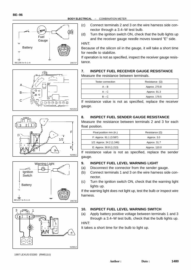
Z05727
FuelGauge
Battery
BE1206 le–5–1–A
21 3
4 5
N21310
A
B
C
N20811
123
F
E
1/2
Z05730
Warning Light
IgnitionSwitch
Battery
BE1217 le–5–1–A
1 2 3
4 5
N20812
13
BE–96–BODY ELECTRICAL COMBINATION METER
1480Author: Date:
1997 LEXUS ES300 (RM511U)
(c) Connect terminals 2 and 3 on the wire harness side con-nector through a 3.4–W test bulb.
(d) Turn the ignition switch ON, check that the bulb lights upand the receiver gauge needle moves toward ”E” side.
HINT:Because of the silicon oil in the gauge, it will take a short timefor needle to stabilize.If operation is not as specified, inspect the receiver gauge resis-tance.
7. INSPECT FUEL RECEIVER GAUGE RESISTANCEMeasure the resistance between terminals.
Tester connection Resistance (Ω)
A – B Approx. 270.8
A – C Approx. 91.3
B – C Approx. 179.5
If resistance value is not as specified, replace the receivergauge.
8. INSPECT FUEL SENDER GAUGE RESISTANCEMeasure the resistance between terminals 2 and 3 for eachfloat position.
Float position mm (in.) Resistance (Ω)
F: Approx. 91.1 (3.587) Approx. 3.0
1/2: Approx. 34.2 (1.346) Approx. 31.7
E: Approx. 30.8 (1.213) Approx. 110.0
If resistance value is not as specified, replace the sendergauge.
9. INSPECT FUEL LEVEL WARNING LIGHT(a) Disconnect the connector from the sender gauge.(b) Connect terminals 1 and 3 on the wire harness side con-
nector.(c) Turn the ignition switch ON, check that the warning light
lights up.If the warning light does not light up, test the bulb or inspect wireharness.
10. INSPECT FUEL LEVEL WARNING SWITCH(a) Apply battery positive voltage between terminals 1 and 3
through a 3.4–W test bulb, check that the bulb lights up.HINT:It takes a short time for the bulb to light up.

N20813
13
N20215
Engine Coolant Temperature Gauge
IgnitionSwitch
Battery
SenderGauge
Z15788
Engine Coolant Temperature Gauge
Wire Harness Side
Test Bulb(3.4 W)
IgnitionSwitch
Battery
1
N21314
A
C
B
–BODY ELECTRICAL COMBINATION METERBE–97
1481Author: Date:
1997 LEXUS ES300 (RM511U)
(b) Submerge the switch in fuel, check that the bulb goes out.If operation is not as specified, replace the sender gauge.
11. INSPECT ENGINE COOLANT TEMPERATURE RE-CEIVER GAUGE OPERATION
(a) Disconnect the connector from the sender gauge.(b) Turn the ignition switch ON and check that the receiver
gauge needle indicates COOL.
(c) Ground terminal on the wire harness side connectorthrough a 3.4–W test bulb.
(d) Turn the ignition switch ON, and check that the bulb lightsup and the receiver gauge needle moves to the hot side.
If operation is as specified, replace the sender gauge.Then recheck the system.If operation is not as specified, measure the receiver gauge re-sistance.
12. INSPECT ENGINE COOLANT TEMPERATURE RE-CEIVER GAUGE RESISTANCE
Measure the resistance between terminals.
Tester connection Resistance (Ω)
A – B Approx. 54.0
A – C Approx. 175.7
B – C Approx. 229.7
HINT:Connect the test leads so that the current from the ohmmetercan flow according to the above order.This circuit includes the diode.If resistance value is not as specified, replace the receivergauge.

N15887
+–
Z14205
IgnitionSwitch
Battery
Warning Light
BE0044 le–1–1–G
1
N06640
BE1217
Warning Light
IgnitionSwitch
Battery
N02346
OFF
ON
12
BE–98–BODY ELECTRICAL COMBINATION METER
1482Author: Date:
1997 LEXUS ES300 (RM511U)
13. INSPECT ENGINE COOLANT TEMPERATURE SEND-ER GAUGE RESISTANCE
Measure the resistance between the terminal and gauge body.
Temperature °C(°F) Resistance (Ω)
50 (122.0) 160 – 240
120 (248.0) 17.1 – 21.2
If resistance value is not as specified, replace the engine cool-ant temperature sender gauge.
14. INSPECT LOW OIL PRESSURE WARNING LIGHT(a) Disconnect the connector from the warning switch and
ground terminal on the wire harness side connector.(b) Turn the ignition switch ON and check that the warning
light lights up.If the warning light does not light up, test the bulb.
15. INSPECT LOW OIL PRESSURE SWITCH(a) Disconnect the connector from the switch.(b) Check that continuity exists between terminal and ground
with the engine stopped.(c) Check that no continuity exists between terminal and
ground with the engine running.HINT:Oil pressure should be over 24.5 kPa (0.25 kgf/cm2, 3.55 psi).If operation is not as specified, replace the switch.
16. INSPECT BRAKE SYSTEM WARNING LIGHT(a) Disconnect the connector from the brake fluid warning
switch.(b) Release the parking brake pedal.(c) Connect the terminals on the wire harness side of the lev-
el warning switch connector.(d) Start the engine, check that the warning light lights up.If the warning light does not light up, test the bulb or wire har-ness.
17. INSPECT BRAKE FLUID LEVEL WARNING SWITCH(a) Remove the reservoir tank cap and strainer.(b) Disconnect the connector.(c) Check that no continuity exists between the terminals with
the switch OFF (float up).(d) Use syphon, etc. to take fluid out of the reservoir tank.(e) Check that continuity exists between the terminals with
the switch ON (float down)

Z14206
Pedal,Stick TYPE
ON
OFF
1
BE1217
Warning Light
IgnitionSwitch
Battery
N20217
Ohmmeter
OFF
ON
Z10258
Wire Harness Side
1 2
Z05732
Warning Light
IgnitionSwitch
Battery1
–BODY ELECTRICAL COMBINATION METERBE–99
1483Author: Date:
1997 LEXUS ES300 (RM511U)
(f) Pour the fluid back in the reservoir tank.If operation is not as specified, replace the switch.18. INSPECT PARKING BRAKE SWITCH(a) Check that continuity exists between the terminal and
switch body with the switch ON (switch pin released).(b) Check that no continuity exists between the terminal and
switch body with the switch OFF (switch pin pushed in).If operation is not as specified, replace the switch or inspectground point.
19. INSPECT WASHER LEVEL WARNING LIGHT(a) Disconnect the connectors from the level warning switch
and parking brake switch.(b) Connect terminals on the wire harness side connector of
the level warning switch connector.(c) Remove the GAUGE fuse and turn the ignition switch ON,
and check that the warning light comes on.If the warning light does not light up, test the bulb.
20. INSPECT WASHER LEVEL WARNING SWITCH(a) Check that no continuity exists between terminals with the
switch OFF (float up).(b) Check that continuity exists between terminals with the
switch ON (float down).If operation is not as specified, replace the switch.
21. INSPECT WINDOW WASHER LEVEL WARNINGSWITCH CIRCUIT
Disconnect the switch connector and inspect the connector onwire harness side.
Tester connection Condition Specified condition
2 – Ground Constant Continuity
If continuity is not as specified, inspect the wire harness orground point.
22. INSPECT OPEN DOOR WARNING LIGHTDisconnect the connector from the door courtesy switch andground terminal 1 on the wire harness side, and check that thewarning light lights up.If the warning light does not light up, inspect the bulb or wire har-ness.

Z15790
Warning Light
Wire Harness Side
IgnitionSwitch
Battery 57 9 10 1112
46 8
2 31
Z07425
Wire Harness Side
1 2 3 4 56 7 8 9 10 11 12
BE0044
Warning Light
IgnitionSwitch
Battery
BE–100–BODY ELECTRICAL COMBINATION METER
1484Author: Date:
1997 LEXUS ES300 (RM511U)
23. INSPECT WARNING LIGHT(a) Disconnect the connector from the light failure sensor and
ground terminal 4 on the wire harness side connector.(b) Start the engine, check that the warning light lights up.If the warning light does not light up, test the bulb or inspect wireharness.
24. INSPECT LIGHT FAILURE SENSOR CIRCUITDisconnect the connector from the sensor and inspect the con-nector on the wire harness side.
Tester connection Condition Specified condition
1 – Ground Constant Continuity*
2 – Ground Constant Continuity*
9 – Ground Constant Continuity*
10 – Ground Constant Continuity*
11 – Ground Constant Continuity*
12 – Ground Constant Continuity*
3 – Ground Light control switch OFF No voltage
3 – Ground Light control switch TAIL or HEAD Battery positive voltage
4.8 – Ground Ignition switch LOCK or ACC No voltage
4.8 – Ground Ignition switch ON Battery positive voltage
7 – Ground Stop light switch OFF No voltage
7 – Ground Stop light switch ON Battery positive voltage
*: There is resistance because this circuit is grounded throughthe bulb.If the circuit is as specified, replace the sensor. If the circuit isnot as specified, inspect the circuits connected to other parts.
25. INSPECT SEAT BELT WARNING LIGHT(a) Remove the integration relay from the instrument panel
junction block.(b) Ground terminal 2 on the integration relay with the con-
nectors still connected.(c) Turn the ignition switch ON and check that the warning
light lights up.If the warning light does not light up, inspect the bulb or wire har-ness.

N19262
ON 1 2
OFF
N21309
Wire Harness Side
1 2
h–2–1–A
N21311
10971
–BODY ELECTRICAL COMBINATION METERBE–101
1485Author: Date:
1997 LEXUS ES300 (RM511U)
26. INSPECT BUCKLE SWITCH CONTINUITY(a) Check that continuity exists between terminals 1 and 2 on
the switch side connector with the switch ON (belt fas-tened).
(b) Check that no continuity exists between terminals 1 and2 on the switch side connector with the switch OFF (beltunfastened).
If operation is not as specified, replace the front seat inner belt.
27. INSPECT BUCKLE SWITCH CIRCUITDisconnect the connector from the switch and inspect the con-nector on wire harness side.
Tester connection Condition Specified condition
2 – Ground Constant Continuity
– Turn the ignition switch ON Chime sounds for 4 – 8 sec.
– Ground terminal 1 and turn the ignition switch ON No chime sound
If the circuit is not as specified, inspect the circuits connectedto other parts.
28. INSPECT INTEGRATION RELAY SEAT BELT WARN-ING SYSTEM OPERATION
(a) Connect the positive (+) lead from the battery to terminals1 and 7.
(b) Connect the terminal 7 to terminal 9 through the 3.4 W testbulb.
(c) Connect the negative (–) lead from the battery to terminal10.
(d) Check that the bulb lights and the buzzer sounds for 4 to8 seconds.
(e) Return to step (a) and operate the chime again.

N21312
109871
N21313
123456789101112
Z13911
Below 40°C(104°F)
2 1
BE–102–BODY ELECTRICAL COMBINATION METER
1486Author: Date:
1997 LEXUS ES300 (RM511U)
(f) Connect the negative (–) lead from the battery to terminal8.
(g) Check that the buzzer stops sounding.HINT:Check the buzzer within a period of 4 to 8 seconds.If operation is not as specified, replace the relay.
29. Seat belt warning :INSPECT INTEGRATION RELAY CIRCUIT
Remove the relay from the junction block No.1 and inspect theconnectors on the junction block side.
Tester connection Condition Specified condition
8 – GroundDriver’s buckle switch OFF
(Seat best unfastened)No continuity
8 – GroundDriver’s buckle switch ON
(Seat best fastened)Continuity
10 – Ground Constant Continuity
1 – Ground Constant Battery positive voltage
7 – Ground
9 – GroundIgnition switch position OFF or ACC No voltage
7 – Ground
9 – GroundIgnition switch position ON Battery positive voltage
If the circuit is as specified, try to replace the relay with a newone.If the circuit is not as specified, inspect the circuits connectedto other parts.
30. INSPECT ENGINE OIL LEVEL WARNING SWITCHCONTINUITY
(a) Check that continuity exists between terminal with theswitch in each position.
(b) Heat the switch to above 60°C (140°F) in an oil bath.

Z13912
Above 60°C(140°F)
2
OFF
1ON
Z05733
Wire Harness Side
1 2
ls–2–1–D
I03031
IgnitionSwitch
Battery
Warning Light
1 2
Z09972
(a) (b)
A
B
CA
C
B
–BODY ELECTRICAL COMBINATION METERBE–103
1487Author: Date:
1997 LEXUS ES300 (RM511U)
(c) Check that continuity exists between terminals with theswitch ON (float up).
(d) Check that no continuity exists between terminals with theswitch OFF (float down).
If operation is not as specified, replace the switch.
31. INSPECT ENGINE OIL LEVEL WARNING SWITCH CIR-CUIT
Disconnect the switch connector and inspect the connector onwire harness side.
Tester connection Condition Specified condition
2 – Ground Constant Continuity
If continuity is not as specified, inspect the wire harness orground point.
32. INSPECT ENGINE OIL LEVEL WARNING LIGHT(a) Disconnect the connector from the switch.(b) Turn the IG switch ON, the warning light lights up.(c) The warning light lights up after 40 sec. from the engine
has started.If the warning light does not light up, inspect bulb or wire har-ness.33. INSPECT LIGHT CONTROL RHEOSTAT
(See page BE–43)
34. INSPECT BULB CHECK RELAY OPERATION(a) Connect the positive (+) lead from the battery to terminal
C through a 1.4–W test bulb and the negative (–) lead toterminal B, check that the test bulb does not light up.
(b) Connect the positive (+) lead from the battery to terminalA and check that the test bulb lights up.
If operation is not as specified, replace the relay.

BE05J–01
BE–104–BODY ELECTRICAL COMBINATION METER
1488Author: Date:
1997 LEXUS ES300 (RM511U)
REASSEMBLYReassembly is in the reverse of the disassembly(See page BE–90).

Z19374
A/C Control PanelAssembly A/C Control Panel A/C Amplifier
Ignition Switch
Instrument Panel Junction Block DEF Fuse HEATER Fuse MIRROR HEATER Fuse Defogger Relay
RH Mirror Mirror Defogger
Defogger WireLH Mirror Mirror Defogger
BE05K–04
–BODY ELECTRICAL DEFOGGER SYSTEMBE–105
1489Author: Date:
1997 LEXUS ES300 (RM511U)
DEFOGGER SYSTEMLOCATION

BE05L–03
N21536
2936 30
N21537
2936 30
ON
N21538
Wire Harness Side
17 18 19 20 21 22 23 24 25 26 27 28 29
30 31 32 33 34 35 36 37 38 39 40 41 42
N14863
1 2
5
3
3 5
21
BE–106–BODY ELECTRICAL DEFOGGER SYSTEM
1490Author: Date:
1997 LEXUS ES300 (RM511U)
INSPECTION1. A/C control panel assembly:
INSPECT DEFOGGER SWITCH OPERATION(a) Connect the positive (+) lead from the battery to terminal
29 and negative (–) lead to terminal 30.(b) Connect the positive (+) lead from the battery to terminal
36 through a 1.4 W test bulb.
(c) Turn the defogger switch ON and check that the test bulband indicator light turn ON, then turn OFF after approx. 15minutes.
If operation is not as specified, proceed to inspect the A/C con-trol assembly.(See page AC–105)
2. INSPECT DEFOGGER SWITCH CIRCUITDisconnect the connector from the switch and inspect the con-nector on wire harness side.
Tester connection Condition Specified condition
30 – Ground Constant Continuity
29 – Ground Ignition switch position ACC or LOCK No voltage
29 – Ground Ignition switch position ON Battery positive voltage
If the circuit is not as specified, inspect the circuits connectedto other parts.
3. INSPECT DEFOGGER RELAY CONTINUITY
Condition Tester connection Specified condition
Constant 1 – 2 Continuity
Apply B+ between
terminals 1 and 2.3 – 5 Continuity
If continuity is not as specified, replace the relay.4. INSPECT DEFOGGER RELAY CIRCUIT
(See page BE–11)

N21211
46
N21539
1 2 34 5 6
h–6–1
Wire Harness Side
BE4029
Tester Probe
Tin Foil
Heat Wire
–BODY ELECTRICAL DEFOGGER SYSTEMBE–107
1491Author: Date:
1997 LEXUS ES300 (RM511U)
5. INSPECT MIRROR DEFOGGER OPERATION(a) Connect the positive (+) lead from the battery to terminal
6 and the negative (–) lead to terminal 4.(b) Check that the mirror becomes warm.HINT:It will take a short time for the mirror to become warm.If the mirror does not become warm, replace the mirror assem-bly.
6. INSPECT MIRROR DEFOGGER CIRCUITDisconnect the connector from the outside mirror and inspectthe connector on the wire harness side.
Tester connection Condition Specified condition
4 – Ground Constant Continuity
6 – GroundIgnition switch position ON
(Defogger switch OFF)No voltage
6 – GroundIgnition switch position ON
(Defogger switch ON)Battery positive voltage
If the circuit is not as specified, inspect the circuits connectedto other parts.
7. INSPECT DEFOGGER WIRENOTICE: When cleaning the glass, use a soft, dry cloth, and
wipe the glass in the direction of the wire. Take carenot to damage the wires.
Do not use detergents or glass cleaners with abrasiveingredients.
When measuring voltage, wind a piece of tin foilaround the top of the negative probe and press the foilagainst the wire with your finger, as shown.
(a) Turn the ignition switch ON.(b) Turn the defogger switch ON.

BE0123
At Center
BE0124
Several Volts0 Volt
BrokenWire
V
BE0150
Masking Tape
Repair Point
BrokenWire
BE0151
BE–108–BODY ELECTRICAL DEFOGGER SYSTEM
1492Author: Date:
1997 LEXUS ES300 (RM511U)
(c) Inspect the voltage at the center of each heat wire.
Voltage Criteria
Approx. 5V Okay (No break in wire)
Approx. 10V or 0V Broken wire
HINT:If there is approximately 10 V, the wire is broken between thecenter of the wire and the positive (+) end. If there is no voltage,the wire is broken between the center of the wire and ground.
(d) Place the voltmeter positive (+) lead against the defoggerpositive (+) terminal.
(e) Place the voltmeter negative (–) lead with the foil stripagainst the heat wire at the positive (+) terminal end andslide it toward the negative (–) terminal end.
(f) The point where the voltmeter deflects from zero to sever-al V is the place where the heat wire is broken.
HINT:If the heat wire is not broken, the voltmeter indicates 0 V at thepositive (+) end of the heat wire but gradually voltage increasesto approx. 12 V as the meter probe moves to the other end.
8. IF NECESSARY, REPAIR DEFOGGER WIRE(a) Clean the broken wire tips with grease, wax and silicone
remover.(b) Place the masking tape along both sides of the wire for
repair.(c) Thoroughly mix the repair agent (Dupont paste No.
4817).
(d) Using a fine tip brush, apply a small amount of the agentto the wire.
(e) After a few minutes, remove the masking tape.(f) Do not repair the defogger wire for at least 24 hours.

Z19362
Instrument Panel Junction Block GAUGE Fuse DOOR Fuse POWER Fuse Power Main Relay Integration Relay
Ignition Switch
Power WindowMaster Switch
Power Window Switch
Power Window Switch
Power Window Motor
Power Window Motor
BE05M–01
–BODY ELECTRICAL POWER WINDOW CONTROL SYSTEMBE–109
1493Author: Date:
1997 LEXUS ES300 (RM511U)
POWER WINDOW CONTROL SYSTEMLOCATION

BE05N–02
N21194
123456
7891011121314
BE–110–BODY ELECTRICAL POWER WINDOW CONTROL SYSTEM
1494Author: Date:
1997 LEXUS ES300 (RM511U)
INSPECTION1. INSPECT POWER WINDOW MASTER SWITCH CON-
TINUITY(a) Inspect the front driver’s switch.Window unlock:
Switch position Tester connection Specified condition
UP 1 – 13 6 – 7 Continuity
OFF 1 – 6 – 13 Continuity
DOWN 1 – 6 7 – 13 Continuity
Window lock:
Switch position Tester connection Specified condition
UP 1 – 13 6 – 7 Continuity
OFF 1 – 6 – 13 Continuity
DOWN 1 – 6 7 – 13 Continuity
If continuity is not as specified, replace the master switch.(b) Inspect the front passenger’s switch.Window unlock:
Switch position Tester connection Specified condition
UP 1 – 5 7 – 12 Continuity
OFF 1 – 5 – 12 Continuity
DOWN 1 – 12 5 – 7 Continuity
Window lock:
Switch position Tester connection Specified condition
UP 7 – 12 Continuity
OFF 5 – 12 Continuity
DOWN 5 – 7 Continuity
If continuity is not as specified, replace the master switch.(c) Inspect the rear left switch.Window unlock:
Switch position Tester connection Specified condition
UP 1 – 9 7 – 10 Continuity
OFF 1 – 9 – 10 Continuity
DOWN 1 – 10 7 – 9 Continuity
Window lock:
Switch position Tester connection Specified condition
UP 7 – 10 Continuity
OFF 9 – 10 Continuity
DOWN 7 – 9 Continuity
If continuity is not as specified, replace the master switch.(d) Inspect the rear right switch.Window unlock:
Switch position Tester connection Specified condition
UP 1 – 14 7 – 11 Continuity
OFF 1 – 11 – 14 Continuity
DOWN 1 – 11 7 – 14 Continuity

N21195
1
7
N21196
1
7
N21197
6
13
N21198
13
6
–BODY ELECTRICAL POWER WINDOW CONTROL SYSTEMBE–111
1495Author: Date:
1997 LEXUS ES300 (RM511U)
Window lock:
Switch position Tester connection Specified condition
UP 7 – 11 Continuity
OFF 11 – 14 Continuity
DOWN 7 – 14 Continuity
If continuity is not as specified, replace the master switch.
2. INSPECT POWER WINDOW MASTER SWITCH ILLU-MINATION
(a) Set the window lock switch to the unlock position.(b) Connect the positive (+) lead from the battery to terminal
7 and the negative (–) lead to terminal 1, and check thatall the illuminations light up.
(c) Set the window lock switch to the lock position, check thatall the passenger’s power window switch illuminations goout.
If operation is not as specified, replace the master switch.
3. INSPECT ONE TOUCH POWER WINDOW SYSTEM/CURRENT OF CIRCUIT (Using an ammeter)
(a) Disconnect the connector from the master switch.(b) Connect the positive (+) lead from the ammeter to termi-
nal 6 on the wire harness side connector and the negative(–) lead to negative (–) terminal of the battery.
(c) Connect the positive (+) lead from the battery to terminal13 on the wire harness side connector.
(d) As the window goes down, check that the current flow isapproximately 7 A.
(e) Check that the current increases up to approximately14.5 A or more when the window stops going down.
HINT:The circuit breaker opens some 4 – 40 seconds after the win-dow stops going down, so that check must be made before thecircuit breaker operates.If the operation is as specified, replace the master switch.
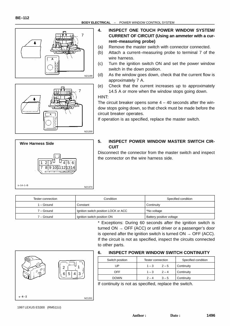
N21199
7
N21200
7
N21374
Wire Harness Side
1 2 3 4 5 67 8 9 1011121314
s–14–1–B
N21201
12
3456
BE–112–BODY ELECTRICAL POWER WINDOW CONTROL SYSTEM
1496Author: Date:
1997 LEXUS ES300 (RM511U)
4. INSPECT ONE TOUCH POWER WINDOW SYSTEM/CURRENT OF CIRCUIT (Using an ammeter with a cur-rent–measuring probe)
(a) Remove the master switch with connector connected.(b) Attach a current–measuring probe to terminal 7 of the
wire harness.(c) Turn the ignition switch ON and set the power window
switch in the down position.(d) As the window goes down, check that the current flow is
approximately 7 A.(e) Check that the current increases up to approximately
14.5 A or more when the window stops going down.HINT:The circuit breaker opens some 4 – 40 seconds after the win-dow stops going down, so that check must be made before thecircuit breaker operates.If operation is as specified, replace the master switch.
5. INSPECT POWER WINDOW MASTER SWITCH CIR-CUIT
Disconnect the connector from the master switch and inspectthe connector on the wire harness side.
Tester connection Condition Specified condition
1 – Ground Constant Continuity
7 – Ground Ignition switch position LOCK or ACC *No voltage
7 – Ground Ignition switch position ON Battery positive voltage
* Exceptions: During 60 seconds after the ignition switch isturned ON → OFF (ACC) or until driver or a passenger’s dooris opened after the ignition switch is turned ON → OFF (ACC).If the circuit is not as specified, inspect the circuits connectedto other parts.
6. INSPECT POWER WINDOW SWITCH CONTINUITY
Switch position Tester connection Specified condition
UP 1 – 3 2 – 5 Continuity
OFF 1 – 3 2 – 4 Continuity
DOWN 2 – 4 3 – 5 Continuity
If continuity is not as specified, replace the switch.

Z07440
Wire Harness Side
1 23 4 5 6
N14863
1 2
5
3
3 5
21
N21202
(a) (b)
12 2 1
–BODY ELECTRICAL POWER WINDOW CONTROL SYSTEMBE–113
1497Author: Date:
1997 LEXUS ES300 (RM511U)
7. INSPECT POWER WINDOW SWITCH CIRCUITDisconnect the connector from the switch and inspect the con-nector on the wire harness side.
Tester connection Condition Specified condition
1 – GroundIgnition switch position ON and
master switch position OFFNo voltage
1 – GroundIgnition switch positrion ON and
master switch position DOWNBattery positive voltage
4 – GroundIgnition switch position ON and
master switch position OFFNo voltage
4 – GroundIgnition switch position ON and
master switch position UPBattery positive voltage
5 – Ground Ignition switch position LOCK or ACC *No voltage
5 – Ground Ignition switch position ON Battery positive voltage
*Exceptions: During 60 seconds period after the ignition switchis turned ON → OFF (ACC) or until driver or a passenger’s dooris opened after the ignition switch is turned ON → OFF (ACC).If the circuit is not as specified, inspect the circuits connectedto other parts.
8. INSPECT POWER MAIN RELAY CONTINUITY
Condition Tester connection Specified condition
Constant 1 – 2 Continuity
Apply B+ between
terminals 1 and 2.3 – 5 Continuity
If continuity is not as specified, replace the relay.9. INSPECT POWER MAIN RELAY CIRCUIT
(See page BE–11)
10. Driver’s Door:INSPECT POWER WINDOW MOTOR OPERATION
(a) Connect the positive (+) lead from the battery to terminal2 and the negative (–) lead to terminal 1, and check thatthe motor turns counterclockwise.
(b) Reverse the polarity, check that the motor turns clock-wise.
If operation is not as specified, replace the motor.

N21203
(a) (b)
12 2 1
N21204
(a) (b)
12 2 1
N21205
(a) (b)
12 2 1
N21206
within4 to 40seconds
13
6
BE–114–BODY ELECTRICAL POWER WINDOW CONTROL SYSTEM
1498Author: Date:
1997 LEXUS ES300 (RM511U)
11. Front Passenger’s Door:INSPECT POWER WINDOW MOTOR OPERATION
(a) Connect the positive (+) lead from the battery to terminal2 and the negative (–) lead to terminal 1, and check thatthe motor turns counterclockwise.
(b) Reverse the polarity, check that the motor turns clock-wise.
If operation is not as specified, replace the motor.
12. Rear Left Side Door:INSPECT POWER WINDOW MOTOR OPERATION
(a) Connect the positive (+) lead from the battery to terminal2 and the negative (–) lead to terminal 1, and check thatthe motor turns counterclockwise.
(b) Reverse the polarity, check that the motor turns clock-wise.
If operation is not as specified, replace the motor.
13. Rear Right Side Door:INSPECT POWER WINDOW MOTOR OPERATION
(a) Connect the positive (+) lead from the battery to terminal2 and the negative (–) lead to terminal 1, and check thatthe motor turns counterclockwise.
(b) Reverse the polarity, check that the motor turns clock-wise.
If operation is not as specified, replace the motor.
14. Driver’s Door:INSPECT POWER WINDOW MOTOR CIRCUITBREAKER OPERATION
(a) Disconnect the connector from the master switch.(b) Connect the positive (+) lead from the battery to terminal
6 and the negative (–) lead to terminal 13 on the wire har-ness side connector and raise the window to full closedposition.
(c) Continue to apply voltage, check that there is a circuitbreaker operation noise within approximately 4 to 40 se-conds.

N21207
6
within60 seconds
13
N21208
within4 to 40seconds
3
2
N21209
3
within60seconds
2
–BODY ELECTRICAL POWER WINDOW CONTROL SYSTEMBE–115
1499Author: Date:
1997 LEXUS ES300 (RM511U)
(d) Reverse the polarity, check that the window begins to de-scend within approximately 60 seconds.
If operation is not as specified, replace the motor.
15. Front Passenger’s Door Motor:INSPECT POWER WINDOW MOTOR CIRCUITBREAKER OPERATION
(a) Disconnect the connector from the power window switch.(b) Connect the positive (+) lead from the battery to terminal
2 and the negative (–) lead to terminal 3 on the wire har-ness side connector, and raise the window to full closedposition.
(c) Continue to apply voltage, check that there is a circuitbreaker operation noise within approximately 4 to 40 se-conds.
(d) Reverse the polarity, check that the window begins to de-scend within approximately 60 seconds.
If operation is not as specified, replace the motor.16. Rear Left Side Door:
INSPECT POWER WINDOW MOTOR CIRCUITBREAKER OPERATION
See step of Front Passenger Door Motor.17. Rear Right Side Door:
INSPECT POWER WINDOW MOTOR CIRCUITBREAKER OPERATION
See step of Front Passenger Door Motor.

N21373
Wire Harness Side
1 2
e–2–1–0
Z19529
(b) Close (c) Open
A3
BE–116–BODY ELECTRICAL POWER WINDOW CONTROL SYSTEM
1500Author: Date:
1997 LEXUS ES300 (RM511U)
18. INSPECT POWER WINDOW MOTOR CIRCUIT(a) Disconnect the connector from the motor.(b) Connect the connector to the master switch and power
window switch.(c) Inspect the connector on the wire harness side.
Driver’s Door Motor
Tester connection Condition Specified condition
1 – Ground *Master switch position DOWN or OFF No voltage
1 – Ground *Master switch position UP Battery positive voltage
2 – Ground *Master switch position UP or OFF No voltage
2 – Ground *Master switch position DOWN Battery positive voltage
Except Driver’s Door Motor
Tester connection Condition Specified condition
1 – Ground *Master switch position UP or OFF No voltage
1 – Ground *Master switch position DOWN Battery positive voltage
1 – Ground *Power window switch position UP or OFF No voltage
1 – Ground *Power window switch position DOWN Battery positive voltage
2 – Ground *Master switch position DOWN or OFF No voltage
2 – Ground *Master switch position UP Battery positive voltage
2 – Ground *Power window switch position DOWN or OFF No voltage
2 – Ground *Power window switch position UP Battery positive voltage
*: Set the window lock switch to the unlock position.(except driv-er’s door motor)If the circuit is not as specified, inspect the circuits connectedto other parts.
19. Key–Off Power Window Signal:INSPECT INTEGRATION RELAY OPERATION
HINT:When the relay circuit is as specified, inspect the key–off powerwindow signal.(a) Connect the positive (+) lead from the voltmeter to termi-
nal A3 and the negative (–) lead to body ground.(b) Close the door with ignition switch turned to LOCK or
ACC, and check that the meter needle indicates batterypositive voltage.

Z19530
A3
–BODY ELECTRICAL POWER WINDOW CONTROL SYSTEMBE–117
1501Author: Date:
1997 LEXUS ES300 (RM511U)
(c) Open the door and check that the meter needle indicates0 V.
(d) Turn the ignition switch ON and check that the meterneedle indicates battery positive voltage again.
If operation is not as specified, replace the relay.20. INSPECT INTEGRATION RELAY CIRCUIT
(See page BE–20)

Z19372
Door Lock Control Switch
Ignition Switch
Power Window Master Switch DOOR Lock Control Switch
Instrument Panel Junction Block DOOR Fuse ECU–IG Fuse Integration Relay
Door Key Lock and Unlock SwitchDoor Lock Assembly Door Lock Motor Door Unlock Detection Switch
Door Lock Assembly Door Lock Motor Door Unlock Detection Switch
BE05O–01
BE–118–BODY ELECTRICAL POWER DOOR LOCK CONTROL SYSTEM
1502Author: Date:
1997 LEXUS ES300 (RM511U)
POWER DOOR LOCK CONTROL SYSTEMLOCATION

BE05P–01
N21194
123456
7891011121314
N21374
Wire Harness Side
1 2 3 4 5 67 8 9 1011121314
s–14–1–B
N21519
12345
–BODY ELECTRICAL POWER DOOR LOCK CONTROL SYSTEMBE–119
1503Author: Date:
1997 LEXUS ES300 (RM511U)
INSPECTION1. Master Switch:
INSPECT DRIVER’S DOOR LOCK CONTROL SW ITCHCONTINUITY
Switch position Tester connection Specified condition
LOCK 1 – 4 Continuity
OFF – No continuity
UNLOCK 1 – 3 Continuity
If continuity is not as specified, replace the switch.
2. Master Switch:INSPECT DRIVER’S DOOR LOCK CONTROL SW ITCHCIRCUIT
Disconnect the connector from the switch and inspect the con-nector on the wire harness side.
Tester connection Condition Specified condition
1 – Ground Constant Continuity
3 – Ground Constant Battery positive voltage
4 – Ground Constant Battery positive voltage
If the circuit is not as specified, inspect the circuits connectedto other parts.
3. INSPECT PASSENGER’S DOOR LOCK CONTROLSWITCH CONTINUITY
Switch position Tester connection Specified condition
LOCK 2 – 3 Continuity
OFF – No continuity
UNLOCK 1 – 2 Continuity
If continuity is not as specified, replace the switch.

N21542
Wire Harness Side
1 2 3 4 5
e–5–1
N20569
UNLOCK
OFF
LOCK
123
N21543
Wire Harness Side
12
3
h–3–1–C
BE–120–BODY ELECTRICAL POWER DOOR LOCK CONTROL SYSTEM
1504Author: Date:
1997 LEXUS ES300 (RM511U)
4. INSPECT PASSENGER’S DOOR LOCK CONTROLSWITCH CIRCUIT
Disconnect the connector from the switch and inspect the con-nector on the wire harness side.
Tester connection Condition Specified condition
2 – Ground Constant Continuity
1 – Ground Constant Battery positive voltage
3 – Ground Constant Battery positive voltage
4 – Ground Ignition switch position LOCK or ACC No voltage
4 – Ground Ignition switch position ON Battery positive voltage
If the circuit is not as specified, inspect the circuits connectedto other parts.
5. INSPECT DOOR KEY LOCK AND UNLOCK SWITCHCONTINUITY
Switch position Tester connection Specified condition
LOCK 1 – 2 Continuity
OFF – No continuity
UNLOCK 1 – 3 Continuity
If continuity is not as specified, replace the switch.
6. INSPECT DOOR KEY LOCK AND UNLOCK SWITCHCIRCUIT
Disconnect the connector from the switch and inspect the con-nector on the wire harness side.
Tester connection Condition Specified condition
1 – Ground Constant Continuity
2 – Ground Constant Battery positive voltage
3 – Ground Constant Battery positive voltage
If the circuit is not as specified, inspect the circuits connectedto other parts.

N20673
Lock
Unlock
4 1
N20570
3 2 23
N21554
3
Front Door Rear Door 2
N21555
Front Door3 2Rear Door
N21556
3
Front Door Rear Door
2
–BODY ELECTRICAL POWER DOOR LOCK CONTROL SYSTEMBE–121
1505Author: Date:
1997 LEXUS ES300 (RM511U)
7. INSPECT DOOR UNLOCK DETECTION SWITCH CON-TINUITY
Switch position Tester connection Specified condition
OFF (Door Lock set to
LOCK)– No continuity
ON (Door Lock set to
UNLOCK)1 – 4 Continuity
If continuity is not as specified, replace the switch.
8. INSPECT MOTOR OPERATION(a) Connect the positive (+) lead from the battery to terminal
3 and the negative (–) lead to terminal 2, and check thatthe door lock link moves to UNLOCK position.
(b) Reverse the polarity and check that the door lock linkmoves to LOCK position.
If operation is not as specified, replace the door lock assembly.
9. INSPECT PTC THERMISTOR OPERATION (Using anammeter)
(a) Connect the positive (+) lead from the battery to terminal3.
(b) Connect the positive (+) lead from the ammeter to termi-nal 2 and the negative (–) lead to battery negative (–) ter-minal, and check that the current changes from approxi-mately 3.2 A to less than 0.5 A within 20 to 70 seconds.
(c) Disconnect the leads from terminals.(d) Approximately 60 seconds later, connect the positive (+)
lead from the battery to terminal 2 and the negative (–)lead to terminal 3, and check that the door lock moves tothe LOCK position.
If operation is not as specified, replace the door lock assembly.
10. INSPECT PTC THERMISTOR OPERATION (Using anammeter with a current–measuring probe)
(a) Connect the positive (+) lead from the battery to terminal3 and the negative (–) lead to terminal 2.
(b) Attach a current–measuring probe to either the positive(+) lead or the negative (–) lead, and check that the cur-rent changes from approximately 3.2 A to less than 0.5 Awithin 20 to 70 seconds.

N21555
Front Door Rear Door3 2
N21544
Wire Harness Side
1 2 3 4
le–4–1–E
Z19531
Lock
A25 A12
BE–122–BODY ELECTRICAL POWER DOOR LOCK CONTROL SYSTEM
1506Author: Date:
1997 LEXUS ES300 (RM511U)
(c) Disconnect the leads from terminals.(d) Approximately 60 seconds later, reverse the polarity, and
check that the door lock moves to the LOCK position.If operation is not as specified, replace the door lock assembly.
11. INSPECT DOOR LOCK ASSEMBLY CIRCUITDisconnect the connector from the switch and inspect the con-nector on the wire harness side.
Tester connection Condition Specified condition
4 – Ground Constant Continuity
1 – Ground
3 – GroundDoor lock manual switch OFF or LOCK No voltage
1 – Ground
3 – GroundDoor lock manual switch UNLOCK Battery positive voltage
2 – Ground Door lock manual switch OFF or UNLOCK No voltage
2 – Ground Door lock manual switch LOCK Battery positive voltage
If the circuit is not as specified, inspect the circuits connectedto other parts.
12. Door Lock Signal:INSPECT INTEGRATION RELAY OPERATION
HINT:When the relay circuit is as specified, inspect the door lock sig-nal.(a) Connect the positive (+) lead from the voltmeter to termi-
nal A12 and the negative (–) lead to terminal A25.(b) Set the door lock control switch to UNLOCK and check
that the voltage rises from 0 V to battery positive voltagefor approximately 0.2 seconds.

Z19532
Unlock
A25 A12
–BODY ELECTRICAL POWER DOOR LOCK CONTROL SYSTEMBE–123
1507Author: Date:
1997 LEXUS ES300 (RM511U)
(c) Reverse the polarity of the voltmeter leads.(d) Set the door lock control switch to LOCK and check that
the voltage rises from 0 V to battery positive voltage forapproximately 0.2 seconds.
If operation is not as specified, replace the relay.13. INSPECT INTEGRATION RELAY CIRCUIT
(See page BE–20)

Z19375
Ignition Switch
Instrument Panel Junction Block GAUGE Fuse POWER Fuse DOOR Fuse Power Main Relay Integration Relay
Sliding Roof Switch Sliding Roof Control Relay
Sliding Roof Motor LImit SwitchEngine Room Junction Block
DOME Fuse
BE05Q–01
BE–124–BODY ELECTRICAL SLIDING ROOF SYSTEM
1508Author: Date:
1997 LEXUS ES300 (RM511U)
SLIDING ROOF SYSTEMLOCATION

BE05R–01
N21643
Wire Harness Side
1 2 3
4 5 6 7 8
s–8–1
N21993
12
N21994
2
1
–BODY ELECTRICAL SLIDING ROOF SYSTEMBE–125
1509Author: Date:
1997 LEXUS ES300 (RM511U)
INSPECTION1. INSPECT SLIDING ROOF CONTROL RELAY AND
SWITCH CIRCUITDisconnect the connector from the relay and switch and inspectthe connector on the wire harness side, as shown in the chart.
Tester connection Condition Specified condition
1 – 5 Constant Continuity
2 – Ground Constant Continuity
3 – Ground No.1 limit switch OFF (Sliding roof closed) No continuity
3 – Ground No.1 limit switch ON (Sliding roof opened) Continuity
7 – GroundNo.2 limit switch OFF (Sliding roof tilted up or
open approx. 200 mm (7.87 in.))No continuity
7 – GroundNo.2 limit switch ON (Except for conditions
mentioned above)Continuity
4 – Ground Ignition switch LOCK or ACC *No voltage
Ignition switch ON Battery positive voltage
*Exceptions: For 60 seconds after the ignition switch is turnedON → OFF (ACC) or until driver or passenger door is openedafter the ignition switch is turned ON → OFF (ACC).If the circuit is as specified, replace the relay and switch.
2. INSPECT SLIDING ROOF MOTOR OPERATION(a) Connect the positive (+) lead from the battery to terminal
1 and the negative (–) lead to terminal 2, check that themotor turns counterclockwise (moves of the close and upside).
(b) Reverse the polarity, check that the motor turns clock-wise. (moves of the open and down side).
If operation is not as specified, replace the motor.

N21180
ON
OFF
No.1Limit Switch
No.2Limit Switch
123456
N21553
Wire Harness Side
1 23 45 6
g–6–1–B
N21644
within10 to 60seconds
BE–126–BODY ELECTRICAL SLIDING ROOF SYSTEM
1510Author: Date:
1997 LEXUS ES300 (RM511U)
3. INSPECT SLIDING ROOF LIMIT SWITCH CONTINUITY
Switch position Tester connection Specified condition
No.1 limit switch OFF
(SW pin released)4 – 5 No continuity
No.1 limit switch ON
(SW pin pushed in)4 – 5 Continuity
No.2 limit switch OFF
(SW pin released)4 – 6 No continuity
No.2 limit switch ON
(SW pin pushed in)4 – 6 Continuity
If continuity is not as specified, replace the switch.
4. INSPECT SLIDING ROOF MOTOR AND LIMIT SWITCHCIRCUIT
Disconnect the connector from the limit switch and inspect theconnector on the wire harness side.
Tester connection Condition Specified condition
3 – Ground Constant Continuity
4 – Ground Constant Continuity
If the circuit is not as specified, inspect the circuits connectedto other parts.
5. INSPECT CIRCUIT BREAKER OPERATION(a) With the sliding roof in the fully opened position, hold the
sliding roof switch in ”OPEN” position and check thatthere is a circuit breaker operation noise within 10 to 60seconds.
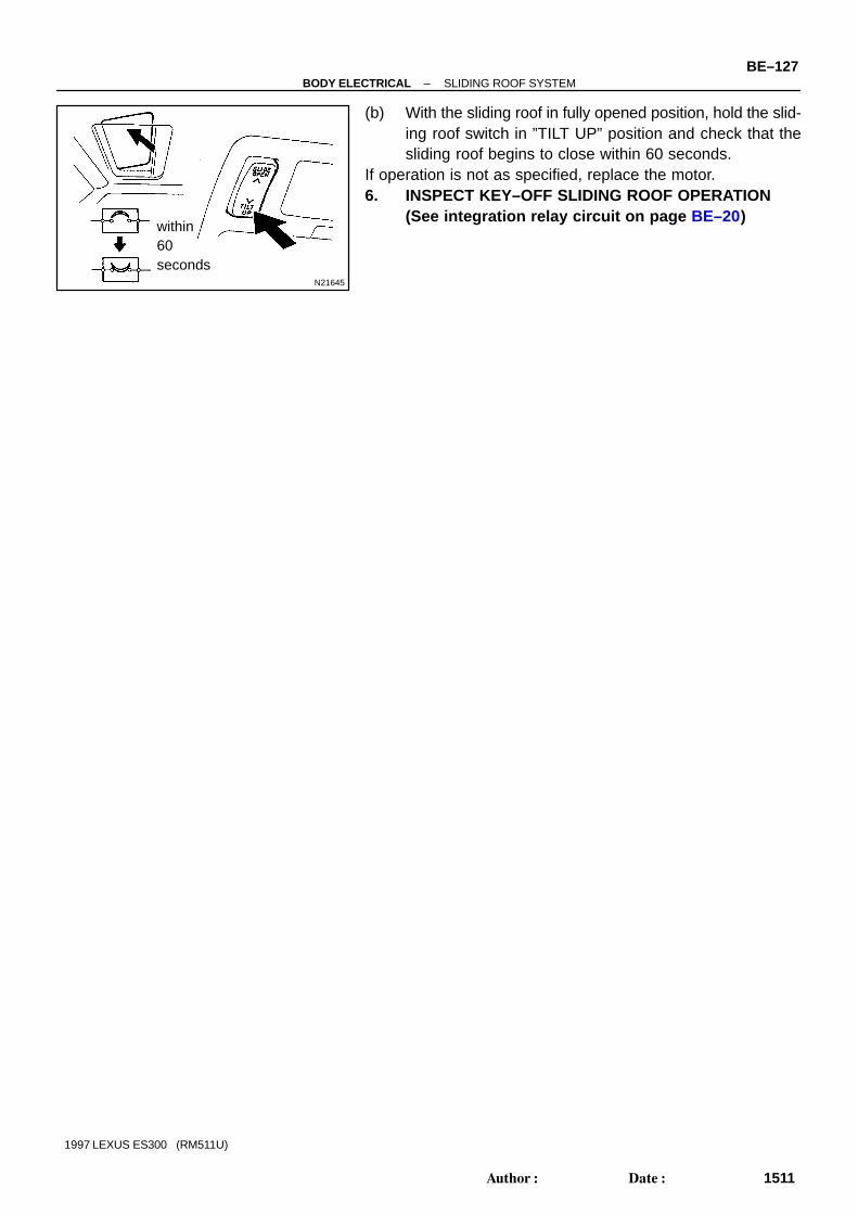
N21645
within60seconds
–BODY ELECTRICAL SLIDING ROOF SYSTEMBE–127
1511Author: Date:
1997 LEXUS ES300 (RM511U)
(b) With the sliding roof in fully opened position, hold the slid-ing roof switch in ”TILT UP” position and check that thesliding roof begins to close within 60 seconds.
If operation is not as specified, replace the motor.6. INSPECT KEY–OFF SLIDING ROOF OPERATION
(See integration relay circuit on page BE–20)

Z19486
Engine Room Junction Block ECU–B Fuse
Instrument Panel Junction Block STOP Fuse GAUGE Fuse ECU–IG Fuse
Reclining Motor
Power Seat Switch
Rear Vertical Motor
Slide Motor
Rear Vertical Motor
Power Seat Switch
Front Vertical Motor
BE05S–01
BE–128–BODY ELECTRICAL POWER SEAT CONTROL SYSTEM
1512Author: Date:
1997 LEXUS ES300 (RM511U)
POWER SEAT CONTROL SYSTEMLOCATION
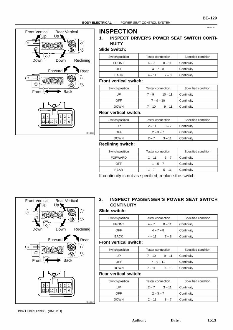
BE05T–03
I01913
Rear VerticalUp
Down Reclining
1
Front VerticalUp
Down
Front Back
2345
6789101112
Forward Rear
I01913
Rear VerticalUp
Down Reclining
1
Front VerticalUp
Down
Front Back
2345
6789101112
Forward Rear
–BODY ELECTRICAL POWER SEAT CONTROL SYSTEMBE–129
1513Author: Date:
1997 LEXUS ES300 (RM511U)
INSPECTION1. INSPECT DRIVER’S POWER SEAT SWITCH CONTI-
NUITYSlide Switch:
Switch position Tester connection Specified condition
FRONT 4 – 7 8 – 11 Continuity
OFF 4 – 7 – 8 Continuity
BACK 4 – 11 7 – 8 Continuity
Front vertical switch:
Switch position Tester connection Specified condition
UP 7 – 9 10 – 11 Continuity
OFF 7 – 9 – 10 Continuity
DOWN 7 – 10 9 – 11 Continuity
Rear vertical switch:
Switch position Tester connection Specified condition
UP 2 – 11 3 – 7 Continuity
OFF 2 – 3 – 7 Continuity
DOWN 2 – 7 3 – 11 Continuity
Reclining switch:
Switch position Tester connection Specified condition
FORWARD 1 – 11 5 – 7 Continuity
OFF 1 – 5 – 7 Continuity
REAR 1 – 7 5 – 11 Continuity
If continuity is not as specified, replace the switch.
2. INSPECT PASSENGER’S POWER SEAT SWITCHCONTINUITY
Slide switch:
Switch position Tester connection Specified condition
FRONT 4 – 7 8 – 11 Continuity
OFF 4 – 7 – 8 Continuity
BACK 4 – 11 7 – 8 Continuity
Front vertical switch:
Switch position Tester connection Specified condition
UP 7 – 10 9 – 11 Continuity
OFF 7 – 9 – 11 Continuity
DOWN 7 – 11 9 – 10 Continuity
Rear vertical switch:
Switch position Tester connection Specified condition
UP 2 – 7 3 – 11 Continuity
OFF 2 – 3 – 7 Continuity
DOWN 2 – 11 3 – 7 Continuity

Z09315
Wire Harness Side
1 2 3 4
5 67 8
9 10
11 1213 14
15 16
eg–16–1
N21865
(a) (b)
2 1 12
N21866
2 1
BE–130–BODY ELECTRICAL POWER SEAT CONTROL SYSTEM
1514Author: Date:
1997 LEXUS ES300 (RM511U)
Reclining switch:
Switch position Tester connection Specified condition
FORWARD 1 – 11 5 – 7 Continuity
OFF 1 – 5 – 7 Continuity
REAR 1 – 7 5 – 11 Continuity
If continuity is not as specified, replace the switch.
3. INSPECT POWER SEAT SWITCH CIRCUIT(a) Disconnect the switch connector and connect the seat
wire harness to the floor wire harness.(b) Inspect the connector on the wire harness side.
Tester connection Condition Specified condition
7 – Ground Constant Continuity
11 – Ground Constant Battery positive voltage
If circuit is not as specified, inspect the circuits connected to oth-er parts.
4. INSPECT SLIDE MOTOR OPERATION(a) Connect the positive (+) lead from the battery to terminal
1 and the negative (–) lead to terminal 2, check that themotor turns counterclockwise.
(b) Reverse the polarity, check that the motor turns clock-wise.
If operation is not as specified, replace the seat adjuster.
5. INSPECT SLIDE MOTOR PTC THERMISTOR OPERA-TION
(a) Connect the positive (+) lead from the battery to terminal1, the positive (+) lead from the ammeter to terminal 2 andthe negative (–) lead to the battery negative (–) terminal,then move the seat cushion to the front position.
(b) Continue to apply voltage, check that current changes toless than 1 ampere within 4 to 90 seconds.

N21867
2 1
N21865
(a) (b)
2 1 12
N22086
2 1
N22087
2 1
N21865
(a)
1
(b)
2 2 1
–BODY ELECTRICAL POWER SEAT CONTROL SYSTEMBE–131
1515Author: Date:
1997 LEXUS ES300 (RM511U)
(c) Disconnect the leads from terminals.(d) Approximately 60 seconds later, connect the positive (+)
lead from the battery to terminal 2 and the negative (–)lead to terminal 1, check that the seat cushion begins tomove backwards.
If operation is not as specified, replace the seat adjuster.
6. INSPECT FRONT VERTICAL MOTOR OPERATION(a) Connect the positive (+) lead from the battery to terminal
1 and the negative (–) lead to terminal 2, check that themotor turns counterclockwise.
(b) Reverse the polarity, check that the motor turns clock-wise.
If operation is not as specified, replace the seat adjuster.
7. INSPECT FRONT VERTICAL MOTOR PTC THERM-ISTOR OPERATION
(a) Connect the positive (+) lead from the battery to terminal1, the positive (+) lead from the ammeter to terminal 2 andthe negative (–) lead to the battery negative (–) terminal,then move the seat cushion to the highest position.
(b) Continue to apply voltage, check that the current changesto less than 1 ampere within 4 to 90 seconds.
(c) Disconnect the leads from the terminals.(d) Approximately 60 seconds later, connect the positive (+)
lead from the battery to terminal 2 and the negative (–)lead to terminal 1, check that the seat cushion begins todescend.
If operation is not as specified, replace the seat adjuster.
8. INSPECT REAR VERTICAL MOTOR OPERATION(a) Connect the positive (+) lead from the battery to terminal
1 and the negative (–) lead to terminal 2, check that themotor turns counterclockwise.
(b) Reverse the polarity, check that the motor turns clock-wise.
If operation is not as specified, replace the seat adjuster.

N22088
2 1
N22089
2 1
N21865
(a) (b)
2 1 12
N21868
2 1
N21869
2 1
BE–132–BODY ELECTRICAL POWER SEAT CONTROL SYSTEM
1516Author: Date:
1997 LEXUS ES300 (RM511U)
9. INSPECT REAR VERTICAL MOTOR PTC THERM-ISTOR OPERATION
(a) Connect the positive (+) lead from the battery to terminal1, the positive (+) lead from the ammeter to terminal 2 andthe negative (–) lead to the battery negative (–) terminal,then move the seat cushion to the highest position.
(b) Continue to apply voltage, check that the current changesto less than 1 ampere within 4 to 90 seconds.
(c) Disconnect the leads from the terminals.(d) Approximately 60 seconds later, connect the positive (+)
lead from the battery to terminal 2 and the negative (–)lead to terminal 1, check that the seat cushion begins todescend.
If operation is not as specified, replace the seat adjuster.
10. INSPECT RECLINING MOTOR OPERATION(a) Connect the positive (+) lead from the battery to terminal
1 and the negative (–) lead to terminal 2, check that themotor turns counterclockwise.
(b) Reverse the polarity, check that the motor turns clock-wise.
If operation is not as specified, replace the seat adjuster.
11. INSPECT RECLINING MOTOR PTC THERMISTOR OP-ERATION
(a) Connect the positive (+) lead from the battery to terminal2, the positive (+) lead from the ammeter to terminal 1 andthe negative (–) lead to the battery negative (–) terminal,then recline the seat back to the most forward position.
(b) Continue to apply voltage, check that the current changesto less than 1 ampere within 4 to 90 seconds.
(c) Disconnect the leads from the terminals.(d) Approximately 60 seconds later, connect the positive (+)
lead from the battery to terminal 1 and the negative (–)lead to terminal 2, check that the seat back starts to fallbackward.
If operation is not as specified, replace the seat adjuster.

N21494
LH Mirror Mirror Motor
Mirror Switch
Ignition SwitchInstrument Panel Junction Block CIG Fuse
RH Mirror Mirror Motor
BE05U–01
–BODY ELECTRICAL POWER MIRROR CONTROL SYSTEMBE–133
1517Author: Date:
1997 LEXUS ES300 (RM511U)
POWER MIRROR CONTROL SYSTEMLOCATION

BE05V–01
N13473
12
34
56789
10
N21376
Wire Harness Side
1 2 3 4 5 6 7 8 910
h–10–1–c
BE–134–BODY ELECTRICAL POWER MIRROR CONTROL SYSTEM
1518Author: Date:
1997 LEXUS ES300 (RM511U)
INSPECTION1. Master switch left side:
INSPECT MIRROR SWITCH CONTINUITY
Switch position Tester connection Specified condition
OFF – No continuity
UP 3 – 4 7 – 8 Continuity
DOWN 3 – 8 4 – 7 Continuity
LEFT 4 – 9 7 – 8 Continuity
RIGHT 4 – 7 8 – 9 Continuity
2. Master switch right side:INSPECT MIRROR SWITCH CONTINUITY
Switch position Tester connection Specified condition
OFF – No continuity
UP2 – 4
1 – 7 – 8Continuity
DOWN4 – 7
1 – 2 – 8Continuity
LEFT4 – 10
1 – 7 – 8Continuity
RIGHT4 – 7
1 – 8 – 10Continuity
If continuity is not as specified, replace the switch.If continuity is as specified. inspect the switch circuit.
3. INSPECT MIRROR SWITCH CIRCUITDisconnect the connector from the switch and inspect the con-nector on the wire harness side.
Tester connection Condition Specified condition
8 – Ground Constant Continuity
4 – Ground Ignition switch position LOCK No voltage
4 – Ground Ignition switch position ACC or ON Battery positive voltage
If the circuit is not as specified, inspect the circuits connectedto other parts.

N13659
6
5
N21212
12 2
1
N21213
32
32
–BODY ELECTRICAL POWER MIRROR CONTROL SYSTEMBE–135
1519Author: Date:
1997 LEXUS ES300 (RM511U)
4. INSPECT INDICATOR LIGHT OPERATIONConnect the positive (+) lead from the battery to terminal 5 andthe negative (–) lead to terminal 6, and check that the indicatorlight does not light up, replace the switch.
5. INSPECT MIRROR MOTOR OPERATION(a) Connect the positive (+) lead from the battery to terminal
1 and the negative (–) lead to terminal 2, and check thatthe mirror turns upward.
(b) Reverse the polarity, and check that the mirror turnsdownward.
(c) Connect the positive (+) lead from the battery to terminal3 and the negative (–) lead to terminal 2, and check thatthe mirror turns to the left side.
(d) Reverse the polarity, and check that the mirror turns to theright side.
If operation is not as specified, replace the mirror.

Z19373
Seat Heater Switch (R)
Ignition Switch
Seat Heater(Seat Back)
Seat Heater Switch (L)Instrument Panel Junction Block SEAT–HEATER Fuse PANEL Fuse Taillight Relay
Seat Heater(Seat Cushion)
BE05W–01
BE–136–BODY ELECTRICAL SEAT HEATER SYSTEM
1520Author: Date:
1997 LEXUS ES300 (RM511U)
SEAT HEATER SYSTEMLOCATION

BE05X–01
N21250
N21372
Z07440
Wire Harness Side
1 2
3 4 5 6
N21540
–BODY ELECTRICAL SEAT HEATER SYSTEMBE–137
1521Author: Date:
1997 LEXUS ES300 (RM511U)
INSPECTION1. INSPECT SEAT HEATER SWITCH CONTINUITY
Condition Tester connection Specified condition
OFF 2 – 6 Continuity
ON 2 – 4 – 6 Continuity
Illumination circuit 1 – 3 Continuity
If continuity is not as specified, replace the switch or bulb.
2. INSPECT SEAT HEATER SWITCH INDICATOR(a) Connect the positive (+) lead from the battery to terminal
4 and the negative (–) lead to terminal 2.(b) Push the switches, check that the indicator lights up.If operation is not as specified, replace the switch and inspectthe circuits connected to other parts.
3. INSPECT SEAT HEATER SWITCH CIRCUITDisconnect the switch connector and inspect the connector onthe wire harness side.
Tester connection Condition Specified condition
2 – Ground Constant *Continuity
6 – Ground Constant *Continuity
4 – Ground Ignition switch position LOCK or ACC No voltage
4 – Ground Ignition switch position ON Battery positive voltage
*: There is resistance because this circuit is grounded throughthe resistance.If the circuit is not as specified, inspect the circuits connectedto other parts.
4. INSPECT SEAT CUSHION CONTINUITY(a) Heat the 2 thermostats with light. Check that there is no
continuity above 45°C (113°F) between terminals 1 and2.
(b) Cool the 2 thermostats below 15°C (59°F). Check thatthere is continuity between terminals 1 and 2.

N21541
BE–138–BODY ELECTRICAL SEAT HEATER SYSTEM
1522Author: Date:
1997 LEXUS ES300 (RM511U)
5. INSPECT SEAT BACK CONTINUITYCheck that there is continuity between terminals 1 and 2.If continuity is not as specified, replace the seat back pad.

Z19376
Fuel Lid Opener Switch
Instrument Panel Junction Block DOOR Fuse
Fuel Lid Opener Solenoid
BE05Y–01
–BODY ELECTRICAL FUEL LID OPENER SYSTEMBE–139
1523Author: Date:
1997 LEXUS ES300 (RM511U)
FUEL LID OPENER SYSTEMLOCATION

BE05Z–01
N21235
ON
N21375
Wire Harness Side
N21210
BE–140–BODY ELECTRICAL FUEL LID OPENER SYSTEM
1524Author: Date:
1997 LEXUS ES300 (RM511U)
INSPECTION1. INSPECT FUEL LID OPENER SWITCH CONTINUITY(a) Check that continuity exists between terminals 2 and 3
with the switch ON.(Switch button pushed)
(b) Check that no continuity exists between terminals 2 and3 with the switch OFF.(Switch button released)
2. INSPECT FUEL LID OPENER SWITCH CIRCUITDisconnect the connector from the switch and inspect the con-nector on the wire harness side, as shown.
Tester connection Condition Specified condition
2 – Ground Constant Continuity
3 – Ground Constant Battery positive voltage
If the circuit is not specified, inspect power source or wire har-ness.
3. INSPECT FUEL LID OPENER SOLENOID OPERATIONConnect the positive (+) lead from the battery to terminal 1 andthe negative (–) lead to terminal 2, and check that the solenoidoperates in the open direction.If operation is not as specified, replace the solenoid.

N21377
Wire Harness Side
–BODY ELECTRICAL FUEL LID OPENER SYSTEMBE–141
1525Author: Date:
1997 LEXUS ES300 (RM511U)
4. INSPECT FUEL LID OPENER SOLENOID CIRCUITDisconnect the connector from the solenoid and inspect theconnector on the wire harness side, as shown.
Tester connection Condition Specified condition
2 – Ground Constant Continuity
1 – Ground Fuel lid opener switch OFF No voltage
1 – Ground Fuel lid opener switch ON Battery positive voltage
If the circuit is not as specified, inspect the circuits connectedto other parts.

The radio wave bands used in radio broadcasting are as follows:
Frequency
Designation
Radio wave
Modulation method
LF: Low frequency MF: Medium Frequency HF: High Frequency VHF: Very High Frequency
Amplitude modulation Frequency modulation
30 kHz 300 kHz 3 MHz 30 MHz 300 MHz
LF MF HF VHF
AM FM
BE060–01
BE2818
FM (Stereo)
FM (Monaural)
AM
BE2819
Fading lonosphere
BE–142–BODY ELECTRICAL AUDIO SYSTEM
1526Author: Date:
1997 LEXUS ES300 (RM511U)
AUDIO SYSTEMDESCRIPTION1. RADIO WAVE BAND
2. SERVICE AREAThere are great differences in the size of the service area for AMand FM monaural. Sometimes FM stereo broadcasts cannot bereceived even through AM can be received in very clearly.Not only does FM stereo have the smallest service area, but italso picks up static and other types of interference (”noise”)easily.
3. RECEPTION PROBLEMSBesides the problem of static, there are also the problemscalled ”fading”, ”multipath” and ”fade out”. These problems arecaused not by electrical noise but by the nature of the radiowaves themselves.
(a) FadingBesides electrical interference, AM broadcasts are alsosusceptible to other types of interference, especially atnight. This is because AM radio waves bounce off the ion-osphere at night. These radio waves then interfere withthe signals from the same transmitter that reach the ve-hicle’s antenna directly. This type of interference is called”fading”.

BE2820
Multipath
BE2821
Fade Out
AM
FM
Noise occurs at a specific place. Strong possibility of foreign noise.
Noise occurs when listening tofaint broadcasting.
Noise occurs only at night.
Noise occurs while driving andat a specific place.
There is a case that the same program is broadcastedfrom each local station and that may be the case you arelistening different station if the program is the same.
Strong possibility of the beat from a distant broadcasting.
Strong possibility of multipath noise and fading noisecaused by the changes of FM waves.
–BODY ELECTRICAL AUDIO SYSTEMBE–143
1527Author: Date:
1997 LEXUS ES300 (RM511U)
(b) MultipathOne type of interference caused by the bounce of radio wavesoff of obstructions is called ”multipath”. Multipath occurs whena signal from the broadcast transmitter antenna bounces offbuildings and mountains and interferes with the signal that is re-ceived directly.
(c) Fade OutBecause FM radio waves are of higher frequencies than AM ra-dio waves, they bounce off buildings, mountains, and other ob-structions. For this reason, FM signals often seem to graduallydisappear or fade away as the vehicle goes behind a buildingor other obstruction. This is called ”fade out”.
4. NOISE PROBLEMS(a) Questionnaire for noise:
It is very important for noise troubleshooting to have goodunderstanding of the claims from the customers, so thatmake the best use of following questionnaire and diag-nose the problem accurately.
HINT:In the case that the noise occurrence condition does not meetany of the above questionnaire, check based on the ”TroublePhenomenon”.Refer to above descriptions for multipath and fading.

N21545
Glass Printed AntennaNoise
Signal
Radio
Noise
Noise
Noise
Noise
N21546
to Radio
Battery
Noise
Choke Coil
BE–144–BODY ELECTRICAL AUDIO SYSTEM
1528Author: Date:
1997 LEXUS ES300 (RM511U)
(b) Matters that require attention when checking: Noise coming into the radio usually has no harm for
practical use as the noise protection is taken and itis hardly thinkable for an extremely loud noise tocome in. When extremely loud noise comes into theradio, check if the grounding is normal where theantenna is installed.
Check if all the regular noise prevention parts areproperly installed and if there is any installation ofnon–authorized parts and non–authorized wiring.
If you leave the radio under out of tune (not tuning),it is easy to diagnose the phenomenon as noise oc-curs frequently.
(c) Antenna and noise:Electronic signal received by the antenna will reach to theradio transmitting through the core wire of the coaxialcable. Any noise wave other than radio wave is mixed intothis core wire, that naturally causes noise in the radio andpoor sound quality. In order to prevent these noises frommixing into the radio, the core wire inside the coaxial cableis covered with a mesh wire called shield wire. This shieldwire shelters the noise and transmits it to the ground, thuspreventing noise from mixing in.
If this shield wire has grounding failure, that causes noise.(d) Choke coil and noise:
The choke coil is connected in the rear window defoggercircuit. This is connected so to prevent noise from mixinginto the radio by making the noise current included in thepower source of the rear window defogger flow to theground.

N21547
Plug (Main)AntennaTerminal (Main)
Plug (Sub) AntennaTerminal (Sub)
1 2
3 4
Z19487
Antenna Code
Choke Coil
Ground PointCenter Brace (RH)
Pillar (LH)
Pillar (RH)
–BODY ELECTRICAL AUDIO SYSTEMBE–145
1529Author: Date:
1997 LEXUS ES300 (RM511U)
(e) Antenna code continuity check and grounding point:HINT:During troubleshooting, in case that the antenna code continu-ity check, grounding check and grounding check of the chokecoil are needed, please check refering to the following illustra-tion.
Terminal connection Normal condition
(1) ↔ (2) Continuity
(3) ↔ (4) No continuity
5. COMPACT DISC PLAYERCompact Disc (hereafter called ”CD”) Players use a laser beampick–up to read the digital signals recorded on the CD and re-produce analog signals of the music, etc. There are 4.7 in. (12cm) and 3.2 in. (8 cm) discs in the CD player.HINT:Never attempt to disassemble or oil any part of the player unit.Do not insert any object other than a disc into the magazine.NOTICE:CD players use an invisible laser beam which could causehazardous radiation exposure. Be sure to operate the play-er correctly as instructed.

N17398
Example :Head Capstan
Pinch Roller
BE4331
BE–146–BODY ELECTRICAL AUDIO SYSTEM
1530Author: Date:
1997 LEXUS ES300 (RM511U)
6. Tape Player/Head Cleaning:MAINTENANCE
(a) Raise the cassette door with your finger.Next, using a pencil or similar object, push in the guide.
(b) Using a cleaning pen or cotton applicator soaked in clean-er, clean the head surface, pinch rollers and capstans.
7. CD Player/Disc Cleaning:MAINTENANCE
If the disc gets dirty, clean the disc by wiping the surface fromthe center to outside in the radial directions with a soft cloth.NOTICE:Do not use a conventional record cleaner or anti–static pre-servative.

BE061–01
–BODY ELECTRICAL AUDIO SYSTEMBE–147
1531Author: Date:
1997 LEXUS ES300 (RM511U)
TROUBLESHOOTINGNOTICE:When replacing the internal mechanism (computer part) of the audio system, be careful that no partof your body or clothing comes in contact with the terminals of the leads from the IC, etc. of the re-placement part (spare part).HINT:This inspection procedure is a simple troubleshooting which should be carried out on the vehicle during sys-tem operation and was prepared on the assumption of system component troubles (except for the wires andconnectors, etc.).Always inspect the trouble taking the following items into consideration.
Open or short circuit of the wire harness Connector or terminal connection fault For audio systems with anti–theft system, troubleshooting items marked ( * ) indicate that ”Trou-
bleshooting for ANTI–THEFT SYSTEM” should be carried out first.
Problem No.
Radio Radio not operating when power switch turned to ’ON’. 1
Display indicates when power switch turned to ’ON’, but no sound (including
’noise’) is produced.2
Noise present, but AM – FM not operating. 3
Any speaker does not work. 4
Either AM or FM does not work. 5
Few preset turning bands. 5
Reception poor. 6
Sound quality poor. 7
Preset memory disappears. 8
Tape Player Cassette tape cannot be inserted. 9
Cassette tape inserts, but no power. 10
Power coming in, but tape player not operating. 11
Any speaker does not work. 12
Sound quality poor. 13
Tape jammed, malfunction with tape speed or auto–reverse. 14
Cassette tape will not eject. 15
CD Player CD cannot be inserted. 16
CD inserted, but no power. 17
Power coming in, but CD player not operating. 18
Sound jumps. 19
Sound quality poor (Volume faint). 20
Any speaker does not work. 21
CD will not be ejected. 22
Noise Noise occurs 23
Noise produced by vibration or shock while driving. 24
Noise produced when engine starts. 25
The term ”AM” includes LW,MW and SW, and the term ”FW” includes UKW.

V08418
Turn ignition Key from LOCK position to ACC position.
Troubleshooting for ANTI–THEFT SYSTEM
Display A:
ID Number is set.
Display E:
ANTI–THEFT SYSTEM opera-
tion condition. (ID number input
error 10 times or more.)
Display B
”SEC display disappears after 1
second.
Radio switch ON.
Take to designated radio
service station.
Display B Display D
Refer to each
malfunction item.
Normal
operation.
Radio switch ON. Normal operation.
Cancel ID number, refer to each malfunction item.
Yes
No
OK
NG
ANTI–THEFT SYSTEM operation condition. (ID number input error 9 times or less.)
Input ID number to cancel ANTI–THEFT SYSTEM, and check display.
Display A→B Display B Display E Display C→A
Radio switch ON. Refer to each
malfunction item.
Take to designated
radio service station.ANTI–THEFT SYSTEM not can-
celled. (ID number input error 10
times or less.)
Display D
ANTI–THEFT SYSTEM cancelled.
Check audio system again.
Normal operation.OK
NG
Cancel ID number, refer to each malfunction item.
Liquid Crystal Display (LCD) or VFD for Audio System
Display ”A” Display ”B” Display ”C” Display ”D” Example:
Display ”E”
2 DIN Type 1 DIN Type
Blank
No Illumination
2 DIN Type 1 DIN Type 2 DIN Type 1 DIN Type
Error Times
2 DIN Type 1 DIN Type
Radio Display
1 DIN Type2 DIN Type
HINT:
Refer to Owner’s Manual for operation details of ANTI–THEFT SYSTEM.
When the ID number has been cancelled, reset the same number after completing the operation, or
inform the customer that it has been cancelled.
BE–148–BODY ELECTRICAL AUDIO SYSTEM
1532Author: Date:
1997 LEXUS ES300 (RM511U)

V08480
1 Radio RADIO NOT OPERATING WHEN POWER SWITCH TURNED TO ”ON”
+ B wire harness faulty.
GND faulty.
Power amplifier or wire harness faulty.
Power amplifier or wire harness faulty.
GND faulty.
Check if GND (wire harness side) to power amplifier is OK?
Is tape player operating normally?
Check if RAD–No.2 fuse is OK?
Is ACC applied to power amplifier?
Is + B applied to power amplifier?
Yes
NG
NoOK
No
No
No
No
OK
OK
OK
Yes
Yes
Yes
Yes
NG
NG
NG
Check if RAD–No.1 fuse is OK?
Is + B applied to radio assembly?
Radio assembly faulty.
Replace fuse.
ACC wire harness faulty.
Is ACC applied to radio assembly?
Check if GND (wire harness side) to radio assembly is OK?
Radio assembly faulty.
Replace fuse.
–BODY ELECTRICAL AUDIO SYSTEMBE–149
1533Author: Date:
1997 LEXUS ES300 (RM511U)
*
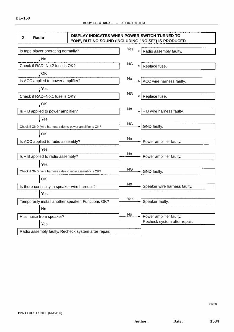
V08481
2 Radio DISPLAY INDICATES WHEN POWER SWITCH TURNED TO”ON”, BUT NO SOUND (INCLUDING ”NOISE”) IS PRODUCED
+ B wire harness faulty.
GND faulty.
Power amplifier faulty.
Speaker wire harness faulty.
GND faulty.
Check if GND (wire harness side) to power amplifier is OK?
Is tape player operating normally?
Check if RAD–No.2 fuse is OK?
Is ACC applied to power amplifier?
Is + B applied to power amplifier?
Yes
NG
NoOK
No
No
No
No
OK
OK
OK
Yes
Yes
Yes
Yes
NG
NG
NG
Check if RAD–No.1 fuse is OK?
Is + B applied to radio assembly?
Radio assembly faulty. Recheck system after repair.
Replace fuse.
ACC wire harness faulty.
Is ACC applied to radio assembly?
Check if GND (wire harness side) to radio assembly is OK?
Radio assembly faulty.
Replace fuse.
Is there continuity in speaker wire harness?
Temporarily install another speaker. Functions OK?
Hiss noise from speaker?
Yes
Yes
No
No
No
Yes
Power amplifier faulty.
Power amplifier faulty.Recheck system after repair.
Speaker faulty.
BE–150–BODY ELECTRICAL AUDIO SYSTEM
1534Author: Date:
1997 LEXUS ES300 (RM511U)
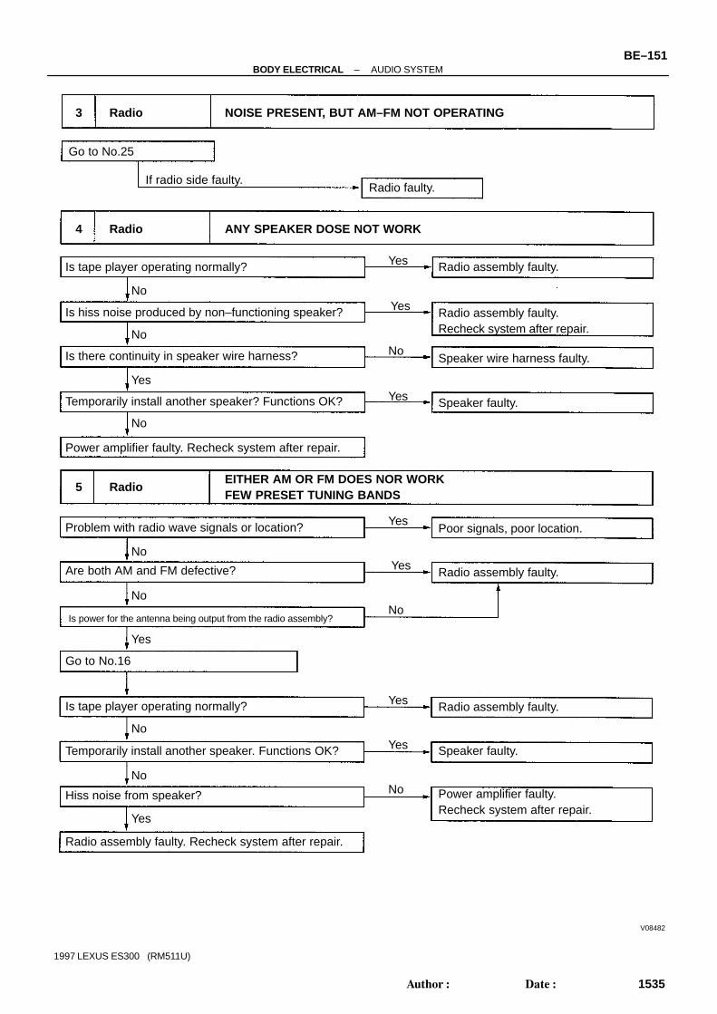
V08482
Speaker wire harness faulty.
Is tape player operating normally? Yes
No
Radio assembly faulty.Recheck system after repair.
Radio assembly faulty.
Temporarily install another speaker? Functions OK?
Power amplifier faulty. Recheck system after repair.
Speaker faulty.
4 Radio ANY SPEAKER DOSE NOT WORK
5 RadioEITHER AM OR FM DOES NOR WORK FEW PRESET TUNING BANDS
Is hiss noise produced by non–functioning speaker?
Is there continuity in speaker wire harness?
Problem with radio wave signals or location?
Are both AM and FM defective?
Yes
Yes
No
Yes
No
No
3 Radio NOISE PRESENT, BUT AM–FM NOT OPERATING
Go to No.25
Radio faulty.If radio side faulty.
Radio assembly faulty.
Go to No.16
Is tape player operating normally? Radio assembly faulty.
Is power for the antenna being output from the radio assembly?
Hiss noise from speaker?
Temporarily install another speaker. Functions OK?
Radio assembly faulty. Recheck system after repair.
Speaker faulty.
Power amplifier faulty.Recheck system after repair.
Poor signals, poor location.
No
Yes
Yes
No
No
No
Yes
Yes
Yes
Yes
No
No
–BODY ELECTRICAL AUDIO SYSTEMBE–151
1535Author: Date:
1997 LEXUS ES300 (RM511U)

V08549
6 Radio POOR RECEPTION
Is the condition bad in comparison with other vehicle?
Are there any additional installation parts?(Sun shade film, telephone antenna, etc.)
Check if there is any scratch and breaking of a wire on
the glass antenna and the defogger pattern.
(visual check. tester)
(See page BE–142)
Is the contact of the plug jack of the radio OK?
Does the condition get better by using the outerantenna (such as pillar antenna)?
Is the contact of the antenna terminal on the glasssurface and the defogger terminal?
Is the continuity of the antenna cord OK?
Check the grounding of the antenna, antenna cord,choke coil, and noise filter. (See page BE–142)
Does the condition get better by exchangingthe choke coil?
Does the condition get better by exchanging theantenna cord?
Take a measure for contact.
An electric wave environment.
Does the condition get better if removing them?
Influence of additional installation parts.Influence of the sun shade film.
Repair. (See page BE–106)
Check the radio.
Take a measure for contact.
Grounding failure.
Exchange the antenna cord.
Exchange the choke coil.
Exchange the antenna cord.
Yes
No
Exchange the glass.
Yes
Yes
Yes
Yes
Yes
Yes
Yes
Yes
No
No
No
No
No
No
No
No
NG
OK
BE–152–BODY ELECTRICAL AUDIO SYSTEM
1536Author: Date:
1997 LEXUS ES300 (RM511U)

V08483
7 Radio SOUND QUALITY POOR
Yes
No Yes
NG
OK
Is sound quality always bad?
Is tape player operating normally?
Poor signals, poorlocation.
Radio assembly faulty.
Install properly.
Speaker faulty.
Is tape player operating normally?
Is speaker properly installed?
Radio assembly or power amplifier faulty.Recheck system after repair.
Temporarily install another speaker. Functions OK?
Is sound quality bad incertain areas only?
Radio assembly or poweramplifier faulty.
Can cassette tape be inserted in tape player?
Check if RADIO No.1 fuse is OK?
Is +B applied to power amplifier?
Check if GND (wire harness side) to power amplifier?
Is +B applied to radio assembly?
Radio assembly faulty.
Replace fuse.
+B wire harness faulty.
GND faulty.
Power amplifier faulty.
8 Radio PRESET MEMORY DISAPPEARS
No
Radio assembly faulty.
No
No
No
No
Yes
Yes
Yes
Power amplifier faulty.Check if GND (wire harness side) to radio assembly?
Radio assembly faulty.
Yes
Yes
Yes
No
No
No
NG
NG
OK
OK
Yes
–BODY ELECTRICAL AUDIO SYSTEMBE–153
1537Author: Date:
1997 LEXUS ES300 (RM511U)

V08484
9 Tape Player CASSETTE TAPE CANNOT BE INSERTED
Yes
No
NG
Is there a foreign object inside tape player?
Is auto search button radio operating normally?
Check if RADIO No.1 fuse is OK?
Is +B applied to power amplifier?
Check if GND (wire harness side) to power amplifier is OK?
Is +B applied to radio assembly?
Check if GND (wire harness side) to radio assembly is OK?
Radio assembly faulty.
Radio assembly faulty.
Remove foreign object.
Replace fuse.
+B wire harness faulty.
GND faulty.
Power amplifier faulty.
Is ACC applied to radio assembly?
Power amplifier faulty.
10 Tape Player CASSETTE TAPE INSERTED, BUT NO POWER
Is radio operating normal?
Check if RAD No.2 fuse is OK?
Is ACC applied to power amplifier?
Is +B applied to power amplifier?
ACC wire harness faulty.
Check if RADIO No.1 fuse is OK?
Radio assembly faulty.
Replace fuse.
Replace fuse.
+B wire harness faulty.
Power amplifier faulty.
Radio assembly faulty.
YesNo
No
OK
Yes
OK
Yes
OK
NG
No
NG
No
No
No
No
OK
OK
Yes
Yes
Yes
Yes
NG
NG
BE–154–BODY ELECTRICAL AUDIO SYSTEM
1538Author: Date:
1997 LEXUS ES300 (RM511U)

V08485
11 Tape Player POWER COMING IN, BUT TAPE PLAYER NOT OPERATING
Yes
No
Radio assembly faulty.
Cassette tape faulty.
Speaker wire harness faulty.
Speaker faulty.
Power amplifier faulty.Recheck system after repair.
Radio assembly faulty.Recheck system after repair.
Radio assembly faulty.
YesNo
No
Yes
Yes
NoNo
No
No
No
Yes
Yes
Yes
Yes
No
Function OK if different cassette tape inserted?
Is radio operating normally?
Is there continuity in speaker wire harness?
Temporarily install another speaker.Function OK?
Hiss noise from speaker?
Radio assembly faulty.Recheck system after repair.
Is radio operating normally?
Speaker wire harness faulty.
Speaker faulty.
Is hiss noise produced by non–functioning speaker.
Is there continuity in speaker wire harness?
Temporarily install another speaker.Function OK?
Radio assembly or power amplifier faulty.
12 Tape Player EITHER SPEAKER DOES NOT WORK
Yes
–BODY ELECTRICAL AUDIO SYSTEMBE–155
1539Author: Date:
1997 LEXUS ES300 (RM511U)

V08486
13 Tape Player SOUND QUALITY POOR (VOLUME FAINT)
Yes
No
Radio assembly faulty.
Cassette tape faulty.
Install properly.
Speaker faulty.
Head dirty.YesNo
No
Yes
Yes
No
No
Function OK if different cassette tape inserted?
Is radio operating normally?
Is speaker properly installed?
Temporarily install another speaker.Function OK?
Radio assembly faulty.
Operates normally after cleaning the heads?
Function OK if different tape (less than 120 mins.) is inserted?
Operates normally after cleaning the heads?
Radio assembly faulty.
Is there a foreign object inside tape player?
Cassette tape faulty.
Remove foreign object.
Head dirty.
14 TAPE JAMMED MALFUNCTION WITH TAPE SPEED OR AUTO–REVERSE
No
No
No
Yes
Yes
Yes
Yes
14 Tape Player TAPE JAMMED MALFUNCTION WITH TAPE SPEED OR AUTO–REVERSE
15 Tape Player CASSETTE TAPE WILL NOT EJECTED
Radio assembly faulty.
Radio assembly faulty.
Is tape player operating normally?
Is auto search button of radio operating normally?
Check if RADIO No.1 fuse is OK?
Is –B applied to power amplifier?
Is +B applied to radio assembly?
Cassette tape jammed.
Replace fuse.
+B wire harness faulty.
Power amplifier faulty.
Yes
Yes
Yes
Yes
No
No
No
No
NG
OK
BE–156–BODY ELECTRICAL AUDIO SYSTEM
1540Author: Date:
1997 LEXUS ES300 (RM511U)

V08487
16 CD Player CD CANNOT BE INSERTED
Yes
No
Is CD already inserted? Eject CD.
Radio assembly
faulty.
Is +B applied to CD player?
Check if GND wire harness side
to CD player is OK?
CD player faulty.
Replace fuse.
+B wire harness faulty.
Check if RADIO No.1 fuse is OK?
Is +B applied to power amplifier?
Check if GND (wire harness side) to radio assembly is OK?
Radio assembly faulty.
Is auto search button of radio operating normally?
No
NoYes
Yes
Yes
NoOK
NG
OK
OK
NG
NG
17 CD Player CD INSERTED, BUT NO POWER
Radio assembly
faulty.
Replace fuse.Check if RADIO No.2 fuse is OK?
Is radio operating normally? Is ACC applied to CD player?
CD player faulty.
ACC wire harness faulty.Is ACC applied to power amplifier?
Power amplifier faulty.
Radio assembly faulty.
Is ACC applied to radio assembly?
No
No
No
NoYes
Yes
Yes
Yes
OK
NG
–BODY ELECTRICAL AUDIO SYSTEMBE–157
1541Author: Date:
1997 LEXUS ES300 (RM511U)
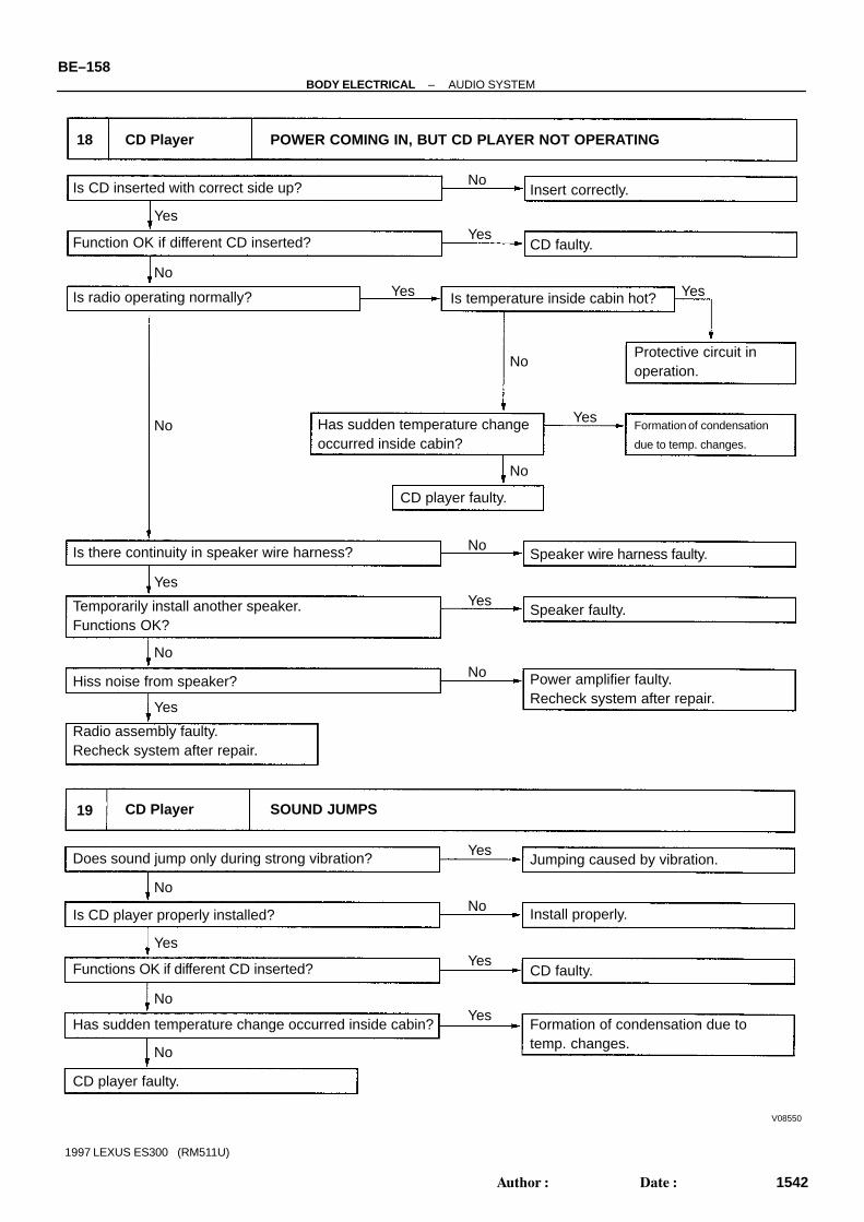
V08550
18 CD Player POWER COMING IN, BUT CD PLAYER NOT OPERATING
Is CD inserted with correct side up?
Is radio operating normally?
Insert correctly.
CD faulty.
Protective circuit inoperation.
Formation of condensation
due to temp. changes.
Function OK if different CD inserted?
Has sudden temperature changeoccurred inside cabin?
CD player faulty.
Is temperature inside cabin hot?
Speaker wire harness faulty.
Speaker faulty.
Power amplifier faulty.Recheck system after repair.
Is there continuity in speaker wire harness?
Temporarily install another speaker.Functions OK?
Hiss noise from speaker?
Radio assembly faulty.Recheck system after repair.
No
YesYes
Yes Yes
Yes
YesYes
Yes
No
No
No
No
No
No
No
CD Player SOUND JUMPS19
CD player faulty.
Does sound jump only during strong vibration?
Is CD player properly installed?
Functions OK if different CD inserted?
Has sudden temperature change occurred inside cabin?
Jumping caused by vibration.
Install properly.
CD faulty.
Formation of condensation due totemp. changes.
Yes
Yes
Yes
Yes
NoNo
No
No
BE–158–BODY ELECTRICAL AUDIO SYSTEM
1542Author: Date:
1997 LEXUS ES300 (RM511U)

V08551
20 CD Player SOUND QUALITY POOR (VOLUME FAINT)
Is radio operating normally?
CD faulty.Function OK if different CD inserted?
CD player faulty.
Speaker faulty.Temporarily install another speaker.Functions OK?
Power amplifier faulty.Recheck system after repair.
Yes
No
Temporarily install another speaker.Function OK?
21 CD Player EITHER SPEAKER DOES NOT WORK
Is speaker property installed?
CD player faulty.
Install properly.
Speaker wire harness faulty.
Speaker faulty.
Is hiss noise produced by non–functioning speaker?
Is there continuity in speaker wire harness?
Is radio operating normally?
Yes
YesYes
Yes
Yes
Yes
Yes
No
No
No
No
No
No
No
Radio assembly or CD player or power amplifier faulty.
Radio assembly faulty.Recheck system after repair.
–BODY ELECTRICAL AUDIO SYSTEMBE–159
1543Author: Date:
1997 LEXUS ES300 (RM511U)

V08488
CD player faulty.
22 CD Player CD WILL NOT BE EJECTED
Is auto search button of radiooperating normally?
No
Is +B applied to CD player? Radio assemblyfaulty.
Replace fuse.
+B wire harness faulty.
Power amplifier faulty.
Radio assembly faulty.
Is +B applied to radio assembly?
Check if RADIO No.1 fuse is OK?
Is +B applied to power amplifier?
No
No
No
Yes
NG
OK
Yes
Yes
Yes
BE–160–BODY ELECTRICAL AUDIO SYSTEM
1544Author: Date:
1997 LEXUS ES300 (RM511U)
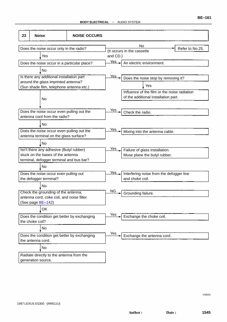
V08552
23 Noise NOISE OCCURS
No
Yes
NG
OK
Does the noise occur only in the radio?
Does the noise occur in a particular place?
Is there any additional installation partaround the glass imprinted antenna?(Sun shade film, telephone antenna etc.)
Does the noise occur even pulling out theantenna cord from the radio?
Does the noise occur even pulling out theantenna terminal on the glass surface?
Isn’t there any adhesive (Butyl rubber)stuck on the bases of the antennaterminal, defogger terminal and bus bar?
Check the grounding of the antenna,antenna cord, coke coil, and noise filter.(See page BE–142)
Does the noise occur even pulling outthe defogger terminal?
Does the condition get better by exchangingthe antenna cord.
Radiate directly to the antenna from thegeneration source.
Does the condition get better by exchangingthe choke coil?
Exchange the antenna cord.
Exchange the choke coil.
Interfering noise from the defogger lineand choke coil.
Grounding failure.
Failure of glass installation.Muse plane the butyl rubber.
Mixing into the antenna cable.
Check the radio.
Influence of the film or the noise radiationof the additional installation part.
Does the noise stop by removing it?
An electric environment.
Refer to No.25.(It occurs in the cassetteand CD.)
Yes
Yes
Yes
Yes
Yes
Yes
Yes
Yes
Yes
No
No
No
No
No
No
No
No
–BODY ELECTRICAL AUDIO SYSTEMBE–161
1545Author: Date:
1997 LEXUS ES300 (RM511U)

V08553
24 Noise NOISE PRODUCED BY VIBRATION OR SHOCK WHILE DRIVING
No
Yes
Is speaker properly installed?
Noise is produced from static eletricity accumulating in the vehicle body.
With vehicles stationary lightly tap each system.Is noise produced?
Install properly.
Each system faulty.
Is speaker properly installed? No
No
YesYes
BE–162–BODY ELECTRICAL AUDIO SYSTEM
1546Author: Date:
1997 LEXUS ES300 (RM511U)

V08554
25 Noise NOISE PRODUCED WHEN ENGINE STARTS
No
YesWhistling noise which becomes high–pitched whenaccelerator strongly depressed, disappears shortlyafter engine stops.
Generator noise.
A/C noise.
Fuel gauge noise.
Horn noise.
Ignition noise.
Turn signal noise.
Washer noise.
Engine coolant temp. gauge noise.
Wiper noise.
Whining noise occurs when A/C is operating.
Scratching noise occurs during sudden acceleration, driving on rough
roads or when ignition switch is turned ON.
Clicking sound is heard when horn button is pressed, then re-
leased. Whirring/grating sound is heard when pushed continu-
ously.
Murmuring sound stops when engine stops.
Tick–tack noise occurs in co–ordination with blinking offlasher.
Noise occurs during window washer operation.
Scratching noise occurs while engine is running,and continues a while even after engine stops.
Scraping noise in line with wiper beat.
Other type of noise
Yes
Yes
Yes
Yes
Yes
Yes
Yes
Yes
No
No
No
No
No
No
No
No
–BODY ELECTRICAL AUDIO SYSTEMBE–163
1547Author: Date:
1997 LEXUS ES300 (RM511U)

BE062–01
Z19355
Tweeter
Ignition Switch Power Amplifier Tweeter
Instrument Panel Junction Block RADIO No.1 Fuse RAD No.2 Fuse
Radio Receiver Assembly
Woofer
CD Auto Changer
Front Speaker
Rear Speaker
BE–164–BODY ELECTRICAL AUDIO SYSTEM
1548Author: Date:
1997 LEXUS ES300 (RM511U)
LOCATION

BE063–01
N21369
Wire Harness Side
N21370
Wire Harness Side
Connector ”A” Connector ”B”
Connector ”C”
–BODY ELECTRICAL AUDIO SYSTEMBE–165
1549Author: Date:
1997 LEXUS ES300 (RM511U)
INSPECTION1. INSPECT CD AUTO CHANGER CIRCUITDisconnect connectors from CD auto changer and inspect theconnector on the wire harness side.
Tester connection Condition Specified condition
8 – Ground Constant Continuity
5 – Ground Constant Battery positive voltage
12 – Ground Ignition switch LOCK No voltage
12 – Ground Ignition switch ACC or ON Battery positive voltage
If the circuit is not as specified, inspect the circuits connectedto other parts.HINT: Check the wire harness between the radio receiver as-
sembly and the CD auto changer. Since the signals to and from the MUTE, R–, R+, L–, L+,
TX– and TX+ terminals are serial signals, they cannot or-dinarily be measured with a tester.
2. INSPECT POWER AMPLIFIER CIRCUITDisconnect the connector from power amplifier and inspect theconnector on the wire harness side.
Tester connection Condition Specified condition
C7 – Ground Constant Continuity
C3 – Ground Ignition switch LOCK No voltage
C3 – Ground Ignition switch ACC or ON Battery positive voltage
C4 – Ground Constant Battery positive voltage
If the circuit is not as specified, inspect the circuits connectedto other parts.
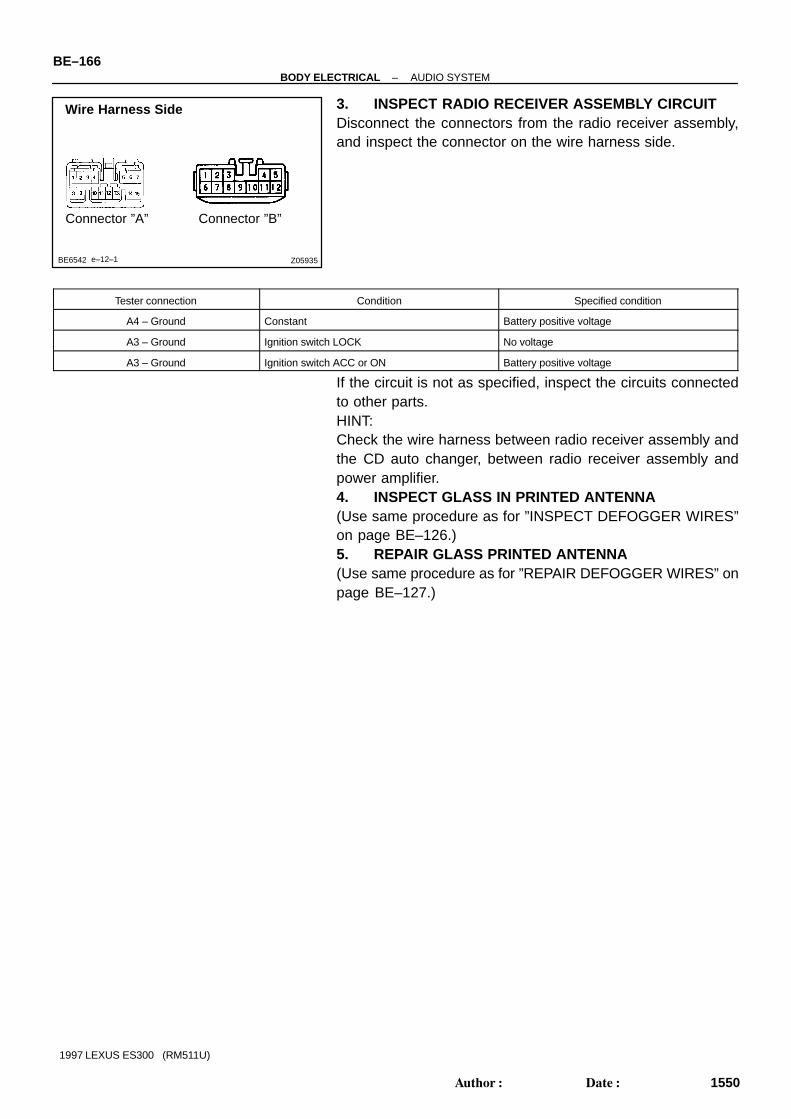
Z05935
Wire Harness Side
Connector ”A” Connector ”B”
BE6542 e–12–1
BE–166–BODY ELECTRICAL AUDIO SYSTEM
1550Author: Date:
1997 LEXUS ES300 (RM511U)
3. INSPECT RADIO RECEIVER ASSEMBLY CIRCUITDisconnect the connectors from the radio receiver assembly,and inspect the connector on the wire harness side.
Tester connection Condition Specified condition
A4 – Ground Constant Battery positive voltage
A3 – Ground Ignition switch LOCK No voltage
A3 – Ground Ignition switch ACC or ON Battery positive voltage
If the circuit is not as specified, inspect the circuits connectedto other parts.HINT:Check the wire harness between radio receiver assembly andthe CD auto changer, between radio receiver assembly andpower amplifier.4. INSPECT GLASS IN PRINTED ANTENNA(Use same procedure as for ”INSPECT DEFOGGER WIRES”on page BE–126.)5. REPAIR GLASS PRINTED ANTENNA(Use same procedure as for ”REPAIR DEFOGGER WIRES” onpage BE–127.)

N21504
BE064–01
–BODY ELECTRICAL ANTENNA CORDBE–167
1551Author: Date:
1997 LEXUS ES300 (RM511U)
ANTENNA CORDREMOVALREMOVE ANTENNA CORD
(a) Remove the following parts: Instrument panel assembly Console box Rear seat Right rear poller garnish Package tray trim Room partition trim
HINT:See BO section(b) Remove antenna cord from glass printed antenna.(c) Disconnect the connectors shown in the illustration.(d) Remove the clips and antenna cord assembly.

BE065–01
BE–168–BODY ELECTRICAL ANTENNA CORD
1552Author: Date:
1997 LEXUS ES300 (RM511U)
INSTALLATIONInstallation is in the reverse order of removal (See page BE–167).

BE066–01
Z04388
E
ILL
B
ACC
2
3
1
Ground
Power Source(Illumination)
Power Source
Power Source(Display Operation)
Connector
(Clock Side) (Wire Harness Side)
14
4
3 2 1 2 3 4(System Operation)
I01417
1 CLOCK WILL NOT OPERATE
(Clock Side) (Wire Harness Side)
Is there battery voltage between terminal+B and body ground?
Open or short circuit in wire harness betweenterminal +B and DOME fuse.
Open circuit in wire harness betweenterminal GND and body ground.
+B GND
Does continuity exist between terminalGND and body ground?
Replace clock.
YesNo
14 3 2 1 2 3 4
No
Yes
(a) Check that the battery positive voltage is 10 –14 V.If voltage is not as specified, replace the battery.
(b) Check that the DOME fuse is not blown.
If the fuse is blown, replace the fuse and check for shortcircuit.
(c) Troubleshoot the clock as follows.HINT: Inspect the connector on the wire harness side.
–BODY ELECTRICAL CLOCKBE–169
1553Author: Date:
1997 LEXUS ES300 (RM511U)
CLOCKTROUBLESHOOTINGHINT:Troubleshoot the clock according to the table below.
Clock will not operate 1
Clock loses or gains time 2
± 1.5 seconds / day

I01418
2 CLOCK LOSES OR GAINS TIME
(Clock Side)
(Wire Harness Side)
Is there 10 – 16 V between terminal +B and bodyground?
Below 10V Detect cause and repair, or recharge battery.
Yes
Adjust or replace clock.
4 3 2 1
4321
(a) Check that the battery positive voltage is 10–16 V.If voltage is not as specified, replace the battery.
(b) Inspect the error of the clock.Allowable error (per day): ± 1.5 sec.If the error exceeds the allowable error, replace the clock.
(c) Check that the clock adjusting button is caught in position, and does not return.
If the button is not returned, repair or replace the clock.
(d) Troubleshoot the clock as follows.
HINT:Inspect the connector on the wire harness side.
BE–170–BODY ELECTRICAL CLOCK
1554Author: Date:
1997 LEXUS ES300 (RM511U)

Z19485
Horn
Horn Switch
Engine RoomJunction Block Horn Relay HORN Fuse
BE067–01
–BODY ELECTRICAL HORN SYSTEMBE–171
1555Author: Date:
1997 LEXUS ES300 (RM511U)
HORN SYSTEMLOCATION

BE068–03
N21863
N21864
N10342
BE–172–BODY ELECTRICAL HORN SYSTEM
1556Author: Date:
1997 LEXUS ES300 (RM511U)
INSPECTION1. INSPECT HORN SWITCH(a) Disconnect the negative (–) terminal from the battery.(b) Remove the left and right covers from the steering wheel.(c) Using a torx socket wrench, loosen the 2 bolts.(d) Pull up the horn pad and place it on the steering column,
as shown.HINT:Do not disconnect the connector from the horn pad.(e) Disconnect the connector from the slip ring.
(f) Check that no continuity exists between terminal 6 of theconnector and body ground.
(g) Check that continuity exists between terminal 6 of theconnector and body ground when the horn contact plateis pressed against the steering spoke assembly.
If continuity is not as specified, repair or replace the steeringwheel or wire harness as necessary.(h) Install the horn pad in place and using a torx socket
wrench, torque the 2 bolts.Torque: 7.1 N·m (72 kgf·cm, 62 in.·lbf)
(i) Install the left and right covers.(j) Connect the negative (–) terminal to the battery.
2. INSPECT HORN OPERATIONConnect the positive (+) lead from the battery to the terminaland negative (–) lead to the horn body and check that the hornblows.If operation is not as specified, replace the horn.

N14863
1 2
5
3
3
1
5
2
–BODY ELECTRICAL HORN SYSTEMBE–173
1557Author: Date:
1997 LEXUS ES300 (RM511U)
3. INSPECT HORN RELAY CONTINUITY
Condition Tester connection Specified condition
Constant 1 – 2 Continuity
Apply B+ between
terminals 1 and 2.3 – 5 Continuity
If continuity is not as specified, replace the relay.