chapter 12 body electrical systems
TRANSCRIPT

12
Chapter 12 Body electrical systems
Bulb renewal . . . . . . . . . . . . . . . . . . . . . . . . . . . . . . . . . . . . . . . . . . . 15Central locking system - description and check . . . . . . . . . . . . . . . . 20Cruise control system - description and check . . . . . . . . . . . . . . . . 19Direction indicator/hazard warning flasher - check and renewal . . . 5Electric windows - description and check . . . . . . . . . . . . . . . . . . . . 21Electrical system fault finding - general information . . . . . . . . . . . . . 2Fuses - general information . . . . . . . . . . . . . . . . . . . . . . . . . . . . . . . 3General information . . . . . . . . . . . . . . . . . . . . . . . . . . . . . . . . . . . . . . 1Headlight housing - removal and refitting . . . . . . . . . . . . . . . . . . . . . 14Headlights - adjustment . . . . . . . . . . . . . . . . . . . . . . . . . . . . . . . . . . 13Headlights - bulb renewal . . . . . . . . . . . . . . . . . . . . . . . . . . . . . . . . . 12
Heated rear window - check and repair . . . . . . . . . . . . . . . . . . . . . . 17Ignition switch - removal and refitting . . . . . . . . . . . . . . . . . . . . . . . . 7Instrument cluster - removal and refitting . . . . . . . . . . . . . . . . . . . . . 10Radio - removal and refitting . . . . . . . . . . . . . . . . . . . . . . . . . . . . . . . 8Radio aerial - removal and refitting . . . . . . . . . . . . . . . . . . . . . . . . . . 9Relays - general information . . . . . . . . . . . . . . . . . . . . . . . . . . . . . . . 4Service Indicator (SI) board - general information . . . . . . . . . . . . . . 11Steering column switches - removal and refitting . . . . . . . . . . . . . . . 6Supplemental Restraint System (SRS) - general information . . . . . . 18Windscreen/tailgate wiper motor - removal and refitting . . . . . . . . . 16Wiring diagrams - general information . . . . . . . . . . . . . . . . . . . . . . . 22
12•1
Easy, suitable fornovice with littleexperience
Fairly easy, suitablefor beginner withsome experience
Fairly difficult,suitable for competentDIY mechanic
Difficult, suitable forexperienced DIYmechanic
Very difficult,suitable for expertDIY or professional
Degrees of difficulty
Contents
1 General information
The chassis electrical system of this vehicleis of 12-volt, negative earth type. Power forthe lights and all electrical accessories issupplied by a lead/acid-type battery, which ischarged by the alternator.
This Chapter covers repair and serviceprocedures for various chassis (non-enginerelated) electrical components. Forinformation regarding the engine electricalsystem components (battery, alternator,distributor and starter motor), see Chapter 5.
Warning: To prevent electricalshort-circuits, fires and injury,always disconnect the batterynegative terminal before
checking, repairing or renewing electricalcomponents.
Caution: If the radio in yourvehicle is equipped with an anti-theft system, make sure you havethe correct activation code
before disconnecting the battery, Refer tothe information on page 0-7 at the front ofthis manual before detaching the cable. Note: If, after connecting the battery, thewrong language appears on the instrumentpanel display, refer to page 0-7 for thelanguage resetting procedure.
2 Electrical system faultfinding - general information 2
A typical electrical circuit consists of anelectrical component, any switches, relays,motors, fuses, fusible links or circuit breakers,etc related to that component, and the wiringand connectors that link the components toboth the battery and the chassis. To help youpinpoint an electrical circuit problem, wiringdiagrams are included at the end of this book.
Before tackling any troublesome electricalcircuit, first study the appropriate wiringdiagrams to get a complete understanding ofwhat makes up that individual circuit.Troublespots, for instance, can often beisolated by noting if other components relatedto that circuit are routed through the samefuse and earth connections.
Electrical problems usually stem fromsimple causes such as loose or corrodedconnectors, a blown fuse, a melted fusiblelink, or a bad relay. Inspect all fuses, wiresand connectors in a problem circuit first.
The basic tools needed include a circuittester, a high-impedance digital voltmeter, acontinuity tester and a jumper wire with an in-line circuit breaker for bypassing electricalcomponents. Before attempting to locate ordefine a problem with electrical test
instruments, use the wiring diagrams todecide where to make the necessaryconnections.
Voltage checksPerform a voltage check first when a circuit
is not functioning properly. Connect one leadof a circuit tester to either the negative batteryterminal or a known good earth.
Connect the other lead to a connector inthe circuit being tested, preferably nearest tothe battery or fuse. If the bulb of the testerlights up, voltage is present, which means thatthe part of the circuit between the connectorand the battery is problem-free. Continuechecking the rest of the circuit in the samefashion.
When you reach a point at which no voltageis present, the problem lies between that pointand the last test point with voltage. Most ofthe time, problems can be traced to a looseconnection. Note: Keep in mind that somecircuits receive voltage only when the ignitionkey is turned to a certain position.
Electrical fault diagnosis is simple if youkeep in mind that all electrical circuits arebasically electricity running from the battery,through the wires, switches, relays, fuses andfusible links to each electrical component(light bulb, motor, etc) and then to earth, fromwhere it is passed back to the battery. Anyelectrical problem is an interruption in the flowof electricity to and from the battery.

Finding a short-circuitOne method of finding a short-circuit is to
remove the fuse and connect a test light orvoltmeter in its place. There should be novoltage present in the circuit. Move theelectrical connectors from side-to-side whilewatching the test light. If the bulb goes on,there is a short to earth somewhere in thatarea, probably where the insulation has beenrubbed through. The same test can beperformed on each component in a circuit,even a switch.
Earth checkPerform a earth check to see whether a
component is properly earthed (passingcurrent back via the vehicle body). Disconnectthe battery, and connect one lead of a self-powered test light (often known as acontinuity tester) to a known good earth.Connect the other lead to the wire or earthconnection being tested. The bulb shouldlight, indicating a good earth connection. Ifnot, dismantle the connection, and clean allrelevant parts thoroughly. When re-makingthe connection, use serrated (shakeproof)washers if possible, and tighten all bolts, etc,securely.
Caution: If the radio in yourvehicle is equipped with an anti-theft system, make sure you havethe correct activation code
before disconnecting the battery, Refer tothe information on page 0-7 at the front ofthis manual before detaching the cable. Note: If, after connecting the battery, thewrong language appears on the instrumentpanel display, refer to page 0-7 for thelanguage resetting procedure.
Continuity checkA continuity check determines if there are
any breaks in a circuit - if it is conductingelectricity properly. With the circuit off (nopower in the circuit), a self-powered continuitytester can be used to check the circuit.Connect the test leads to both ends of thecircuit, and if the test light comes on, thecircuit is passing current properly. If the lightdoesn’t come on, there is a break somewherein the circuit. The same procedure can beused to test a switch, by connecting thecontinuity tester to the power-in and power-out sides of the switch. With the switch turnedon, the test light should come on.
Finding an open-circuitWhen diagnosing for possible open-
circuits, it is often difficult to locate them bysight, because oxidation or terminalmisalignment are hidden by the connectors.Intermittent problems are often caused byoxidised or loose connections. Merelywiggling an electrical connector may correctthe open-circuit condition, albeit temporarily.Dismantle the connector, and spray with awater-dispersant aerosol. On simplerconnectors, it may be possible to carefully
bend the connector pins inside, to improvethe metal-to-metal contact - don’t damagethe connector in the process, however.
3 Fuses - general information 1The electrical circuits of the vehicle are
protected by a combination of fuses andcircuit breakers. The fusebox is located in theleft corner of the engine compartment (seeillustration). On some later models, it islocated under the rear seat cushion.
Each of the fuses is designed to protect aspecific circuit, and on some models, thevarious circuits are identified on the fusepanel itself.
Miniaturised fuses are employed in thefuseboxes. These compact fuses, with bladeterminal design, allow fingertip removal andrenewal. If an electrical component fails,always check the fuse first. A blown fuse iseasily identified through the clear plasticbody. Visually inspect the element forevidence of damage. If a continuity check iscalled for, the blade terminal tips are exposedin the fuse body.
Be sure to renew blown fuses with thecorrect type. Fuses of different ratings arephysically interchangeable, but only fuses ofthe proper rating should be used. Replacing afuse with one of a higher or lower value thanspecified is not recommended. Each electricalcircuit needs a specific amount of protection.The amperage value of each fuse is mouldedinto the fuse body.
If the new fuse immediately fails, don’trenew it again until the cause of the problemis isolated and corrected. In most cases, thecause will be a short-circuit in the wiringcaused by a broken or deteriorated wire.
4 Relays - general information 1Several electrical accessories in the vehicle
use relays to transmit the electrical signal tothe component. If the relay is defective, that
component will not operate properly. Relaysare electrically-operated switches, which areoften used in circuits drawing high levels ofcurrent, or where more complex switchingarrangements are required.
The various relays are grouped together forconvenience in several locations under thedash and in the engine compartment (seeaccompanying illustration and illus-tration 3.1).
If a faulty relay is suspected, it can beremoved and tested by a dealer or qualifiedautomotive electrician. No overhaul ispossible. Like fuses, defective relays must bereplaced with the correct type; some relayslook identical, but perform very differentfunctions.
5 Direction indicator/hazardwarning flasher unit - checkand renewal
2Warning: Some later models areequipped with an airbag orSupplemental Restraint System(SRS). To avoid possible damage
to this system, the manufacturerrecommends that, on airbag-equippedmodels, the following procedure should beleft to a dealer service department, orother specialist, because of the specialtools and techniques required. There is arisk of injury if the airbag is accidentallytriggered.1 The direction indicator/hazard flasher unit isa small canister- or box-shaped unit locatedin the wiring harness on or near the steeringcolumn. Access is gained by removing thesteering column shrouds (see illustration).2 When the flasher unit is functioningproperly, a regular clicking noise can be heardfrom it when the indicators or hazard flashersare switched on. If the direction indicators failon one side or the other, and the flasher unitdoes not make its characteristic clickingsound, a faulty direction indicator bulb isindicated.3 If both direction indicators fail to blink, theproblem may be due to a blown fuse, a faultyflasher unit, a broken switch or a loose or openconnection. If a quick check of the fusebox
12•2 Body electrical systems
4.2 Engine compartment relays3.1 The fusebox is located in the engine
compartment under a cover - the box alsoincludes several relays

indicates that the direction indicator and/orhazard fuse has blown, check the wiring for ashort-circuit before fitting a new fuse.4 Make sure that the new unit is identical tothe original. Compare the old one to the newone before fitting it.5 Refitting is the reverse of removal.
6 Steering column switches -removal and refitting 1
Warning: Some later models areequipped with an airbag orSupplemental Restraint System(SRS). To avoid possible damage
to this system, the manufacturerrecommends that, on airbag-equippedmodels, the following procedure should beleft to a dealer service department, orother specialist, because of the specialtools and techniques required. There is arisk of injury if the airbag is accidentallytriggered.
Caution: If the radio in yourvehicle is equipped with an anti-theft system, make sure you havethe correct activation code
before disconnecting the battery, Refer tothe information on page 0-7 at the front ofthis manual before detaching the cable. Note: If, after connecting the battery, thewrong language appears on the instrumentpanel display, refer to page 0-7 for thelanguage resetting procedure.1 Disconnect the battery negative cable,remove the steering wheel (see Chapter 10)and steering column shrouds (see Chapter 11).
Direction indicator/headlightswitch2 Where necessary, remove the switchmounting screws. Depress the tabs and pullthe switch out of the steering columnmounting (see illustration).3 Trace the switch wires down the steeringcolumn to the electrical connector, andunplug them (see illustration).4 Refitting is the reverse of removal.
Wiper/washer switch5 Where necessary, remove the switchmounting screws.6 Depress the release clip, and detach theswitch from the steering column mounting(see illustration). Trace the switch wiringdown the steering column to the electricalconnector, and unplug it.7 Refitting is the reverse of removal.
Cruise control switch8 Remove the wiper/washer switch.9 Where necessary, remove the switchmounting screw. Squeeze the release tabs,and withdraw the switch from the mounting(see illustration).10 Disconnect the switch electricalconnector from the harness at the base of thesteering column.11 Refitting is the reverse of removal.
7 Ignition switch - removal and refitting 1
Warning: Some later models areequipped with an airbag orSupplemental Restraint System(SRS). To avoid possible damage
to this system, the manufacturerrecommends that, on airbag-equippedmodels, the following procedure should beleft to a dealer service department, orother specialist, because of the special
tools and techniques required. There is arisk of injury if the airbag is accidentallytriggered.
Caution: If the radio in yourvehicle is equipped with an anti-theft system, make sure you havethe correct activation code
before disconnecting the battery, Refer tothe information on page 0-7 at the front ofthis manual before detaching the cable. Note: If, after connecting the battery, thewrong language appears on the instrumentpanel display, refer to page 0-7 for thelanguage resetting procedure.
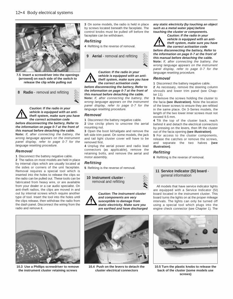
Removal1 Disconnect the battery negative cable.2 Remove the steering wheel (see Chap-ter 10).3 Remove the steering column shrouds (seeChapter 11).4 Where necessary, remove the directionindicator/headlight control switch (see Sec-tion 6).5 Detach the clips by inserting a smallscrewdriver into the openings on the sideswhile pulling out on the switch (seeillustration).6 Unplug the electrical connector from theharness at the base of the steering column,and remove the switch.
Refitting7 Refitting is the reverse of removal.
Body electrical systems 12•3
6.3 Follow the wiring down the steeringcolumn to the connector
6.2 Squeeze the tabs to release the switchfrom the mounting
6.9 Cruise control switch removal6.6 Squeeze the wiper/washer switch tabsand pull it directly out of the mounting
12
5.1 The direction indicator/hazard warningflasher unit is located on the steeringcolumn on most models - squeeze the
tabs to detach it
8 Radio - removal and refitting 1Caution: If the radio in yourvehicle is equipped with an anti-theft system, make sure you havethe correct activation code
before disconnecting the battery, Refer tothe information on page 0-7 at the front ofthis manual before detaching the cable. Note: If, after connecting the battery, thewrong language appears on the instrumentpanel display, refer to page 0-7 for thelanguage resetting procedure.
Removal1 Disconnect the battery negative cable.2 The radios on most models are held in placeby internal clips which are usually located atthe sides or corners of the unit faceplate.Removal requires a special tool which isinserted into the holes to release the clips sothe radio can be pulled out. These tools can befabricated from heavy wire, or are availablefrom your dealer or a car audio specialist. Onanti-theft radios, the clips are moved in andout by internal screws which require anothertype of tool. Insert the tool into the holes untilthe clips release, then withdraw the radio fromthe dash panel. Disconnect the wiring from theradio and remove it.
3 On some models, the radio is held in placeby screws located beneath the faceplate. Thecontrol knobs must be pulled off before thefaceplate can be withdrawn.
Refitting4 Refitting is the reverse of removal.
9 Aerial - removal and refitting 1Caution: If the radio in yourvehicle is equipped with an anti-theft system, make sure you havethe correct activation code
before disconnecting the battery, Refer tothe information on page 0-7 at the front ofthis manual before detaching the cable. Note: If, after connecting the battery, thewrong language appears on the instrumentpanel display, refer to page 0-7 for thelanguage resetting procedure.
Removal1 Disconnect the battery negative cable.2 Use circlip pliers to unscrew the aerialmounting nut.3 Open the boot lid/tailgate and remove theleft side trim panel. On some models, the jackand tail light cluster cover will have to beremoved first.4 Unplug the aerial power and radio leadconnectors (as applicable), remove theretaining bolts, and remove the aerial andmotor assembly.
Refitting5 Refitting is the reverse of removal.
10 Instrument cluster - removal and refitting 2
Caution: The instrument clusterand components are verysusceptible to damage fromstatic electricity. Make sure youare earthed and have discharged
any static electricity (by touching an objectsuch as a metal water pipe) beforetouching the cluster or components.
Caution: If the radio in yourvehicle is equipped with an anti-theft system, make sure you havethe correct activation code
before disconnecting the battery, Refer tothe information on page 0-7 at the front ofthis manual before detaching the cable. Note: If, after connecting the battery, thewrong language appears on the instrumentpanel display, refer to page 0-7 for thelanguage resetting procedure.
Removal1 Disconnect the battery negative cable.2 As necessary, remove the steering columnshrouds and lower trim panel (see Chap-ter 11).3 Remove the screws holding the cluster tothe facia (see illustration). Note the locationof the lower screws to ensure they are refittedin the same place. On 3-Series models, thelength of the two lower inner screws must notexceed 9.5 mm.4 Tilt the top of the cluster back, reachbehind it and detach the electrical connectorsby pressing on the levers, then lift the clusterout of the facia opening (see illustration).5 For access to the cluster components,release the catches or remove the screws,and separate the two halves (seeillustration).
Refitting6 Refitting is the reverse of removal.
11 Service Indicator (SI) board -general information
All models that have service indicator lightsare equipped with a Service Indicator (SI)board located in the instrument cluster. Thisboard turns the lights on at the proper mileageintervals. The lights can only be turned offusing a special tool which plugs into theengine check connector (see Chapter 1). The
12•4 Body electrical systems
10.5 Turn the plastic knobs to release theback of the cluster (some models use
screws)
10.4 Push on the levers to detach thecluster electrical connectors
10.3 Use a Phillips screwdriver to removethe instrument cluster retaining screws
7.5 Insert a screwdriver into the openings(arrowed) on each side of the switch to
release the clip while pulling out
SI board is a self-contained computer whichincludes a chip and batteries.
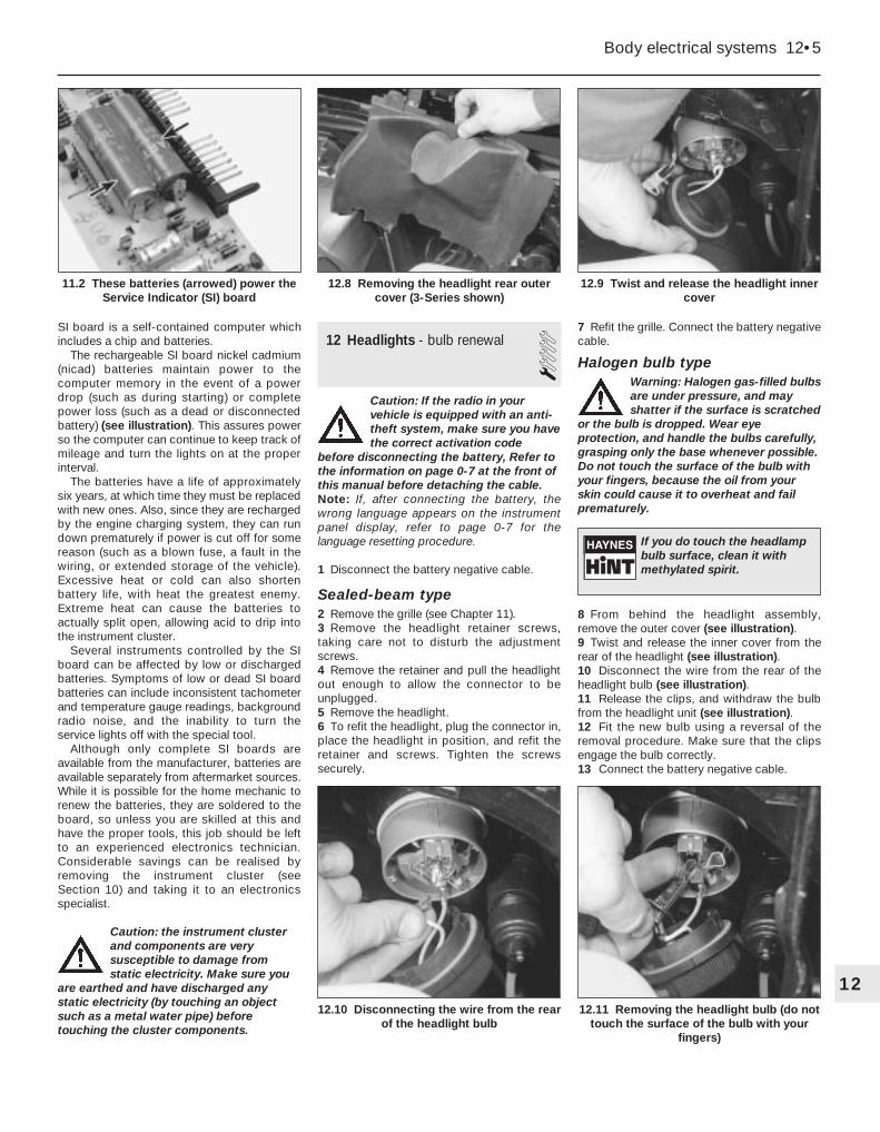
The rechargeable SI board nickel cadmium(nicad) batteries maintain power to thecomputer memory in the event of a powerdrop (such as during starting) or completepower loss (such as a dead or disconnectedbattery) (see illustration). This assures powerso the computer can continue to keep track ofmileage and turn the lights on at the properinterval.
The batteries have a life of approximatelysix years, at which time they must be replacedwith new ones. Also, since they are rechargedby the engine charging system, they can rundown prematurely if power is cut off for somereason (such as a blown fuse, a fault in thewiring, or extended storage of the vehicle).Excessive heat or cold can also shortenbattery life, with heat the greatest enemy.Extreme heat can cause the batteries toactually split open, allowing acid to drip intothe instrument cluster.
Several instruments controlled by the SIboard can be affected by low or dischargedbatteries. Symptoms of low or dead SI boardbatteries can include inconsistent tachometerand temperature gauge readings, backgroundradio noise, and the inability to turn theservice lights off with the special tool.
Although only complete SI boards areavailable from the manufacturer, batteries areavailable separately from aftermarket sources.While it is possible for the home mechanic torenew the batteries, they are soldered to theboard, so unless you are skilled at this andhave the proper tools, this job should be leftto an experienced electronics technician.Considerable savings can be realised byremoving the instrument cluster (see Section 10) and taking it to an electronicsspecialist.
Caution: the instrument clusterand components are verysusceptible to damage fromstatic electricity. Make sure you
are earthed and have discharged anystatic electricity (by touching an objectsuch as a metal water pipe) beforetouching the cluster components.
12 Headlights - bulb renewal 1Caution: If the radio in yourvehicle is equipped with an anti-theft system, make sure you havethe correct activation code
before disconnecting the battery, Refer tothe information on page 0-7 at the front ofthis manual before detaching the cable. Note: If, after connecting the battery, thewrong language appears on the instrumentpanel display, refer to page 0-7 for thelanguage resetting procedure.
1 Disconnect the battery negative cable.
Sealed-beam type2 Remove the grille (see Chapter 11).3 Remove the headlight retainer screws,taking care not to disturb the adjustmentscrews.4 Remove the retainer and pull the headlightout enough to allow the connector to beunplugged.5 Remove the headlight.6 To refit the headlight, plug the connector in,place the headlight in position, and refit theretainer and screws. Tighten the screwssecurely.
7 Refit the grille. Connect the battery negativecable.
Halogen bulb typeWarning: Halogen gas-filled bulbsare under pressure, and mayshatter if the surface is scratched
or the bulb is dropped. Wear eyeprotection, and handle the bulbs carefully,grasping only the base whenever possible.Do not touch the surface of the bulb withyour fingers, because the oil from yourskin could cause it to overheat and failprematurely.
8 From behind the headlight assembly,remove the outer cover (see illustration).9 Twist and release the inner cover from therear of the headlight (see illustration).10 Disconnect the wire from the rear of theheadlight bulb (see illustration).11 Release the clips, and withdraw the bulbfrom the headlight unit (see illustration).12 Fit the new bulb using a reversal of theremoval procedure. Make sure that the clipsengage the bulb correctly.13 Connect the battery negative cable.
Body electrical systems 12•5
12.9 Twist and release the headlight innercover
12.8 Removing the headlight rear outercover (3-Series shown)
11.2 These batteries (arrowed) power theService Indicator (SI) board
12.11 Removing the headlight bulb (do nottouch the surface of the bulb with your
fingers)
12.10 Disconnecting the wire from the rearof the headlight bulb
12
If you do touch the headlampbulb surface, clean it withmethylated spirit.

13 Headlights - adjustment 2Note: The headlights must be aimed correctly.If adjusted incorrectly, they could momentarilyblind the driver of an oncoming vehicle andcause a serious accident, or seriously reduceyour ability to see the road. The headlightsshould be checked for proper aim every 12 months (as is done during the MOT test),and any time a new headlight is fitted or front-end body work is performed. It should beemphasised that the following procedure willonly provide a temporary setting until theheadlights can be adjusted by a properly-equipped garage.1 Each headlight has two adjusting screws,one controlling up-and-down movement andone controlling left-and-right movement (seeillustration). It may be necessary to removethe grille (see Chapter 11) for access to thesescrews.2 There are several methods of adjusting theheadlights. The simplest method requires ablank wall (or garage door) 25 feet in front ofthe vehicle, and a level floor.3 Position masking tape vertically on the wall,to mark the vehicle centreline and thecentreline of both headlights. Note: It may beeasier to position the tape on the wall with thevehicle parked only a few inches away, andthen move the vehicle back the requireddistance when all marks have been made.4 Make a horizontal line on the wall to markthe centreline of all headlights.5 Move the vehicle back so that it is 25 feetaway from the marked wall (keep the front endof the vehicle square to the wall). Adjustmentshould be made with the vehicle sitting level,the fuel tank half-full, and with no unusuallyheavy loads in the vehicle.6 Switch on the dipped beam. The brightspots on the wall should be two inches belowthe horizontal line, and two inches to the leftof the headlight vertical lines. Adjustment ismade by turning the adjusting screw to raiseor lower the beam. The other adjusting screw
should be used in the same manner to movethe beam left or right.7 With main beam on, the bright spots on thewall should be exactly on the vertical lines,and just below the horizontal line. Note: It maynot be possible to position the headlight aimexactly for both main and dipped beams. If acompromise must be made, keep in mind thatthe dipped beam is most used, and will havethe greatest effect on driver safety.8 Have the headlights adjusted by a dealerservice department or qualified garage at theearliest opportunity.
14 Headlight housing - removal and refitting 1
Caution: If the radio in yourvehicle is equipped with an anti-theft system, make sure you havethe correct activation code
before disconnecting the battery, Refer tothe information on page 0-7 at the front ofthis manual before detaching the cable. Note: If, after connecting the battery, thewrong language appears on the instrumentpanel display, refer to page 0-7 for thelanguage resetting procedure.
Removal1 Disconnect the battery negative cable.
2 Remove the side grille (see Chapter 11),then remove the rear cover(s) wherenecessary.3 Unplug the headlight (sealed beam-type) orremove the bulb (halogen bulb-type).4 Remove the screws and detach the housing(see illustration).
Refitting5 Refitting is the reverse of removal.
15 Bulb renewal 11 The lenses of many lights are held in placeby screws, which makes it a simple procedureto gain access to the bulbs.2 On some lights, the lenses are held in placeby clips. The lenses can be removed by usinga small screwdriver to prise them off.3 Several bulbs are mounted in self-earthingholders, and are removed by pushing in andturning them anti-clockwise (see illustration).The bulbs can then be removed (seeillustrations).4 The tail lights on 3-Series models areaccessible after removing the housing, thenremoving the bulbs (see illustrations).5 To gain access to the facia lights, theinstrument cluster will have to be removedfirst (see illustration).
12•6 Body electrical systems
15.3c . . . then pull the bulb from theholder
15.3b On models with high-mountedcentre brake lights, the self-earthing
holder is accessible from the luggage area- pull the holder out . . .
15.3a The tail light bulbs on later 5-Seriesmodels are in self-earthing holders whichcan be simply pulled out of the housing -the bulb is then removed from the holder
14.4 Remove the screws (arrowed) anddetach the headlight housing
13.1 The headlight adjustment screws(arrowed) are accessible from the back of
the headlight on 3-Series models
16 Windscreen/tailgate wipermotor - removal and refitting 2
Caution: If the radio in yourvehicle is equipped with an anti-theft system, make sure you havethe correct activation code
before disconnecting the battery, Refer tothe information on page 0-7 at the front ofthis manual before detaching the cable. Note: If, after connecting the battery, thewrong language appears on the instrumentpanel display, refer to page 0-7 for thelanguage resetting procedure.
1 Disconnect the battery negative cable.
Windscreen wiper motor
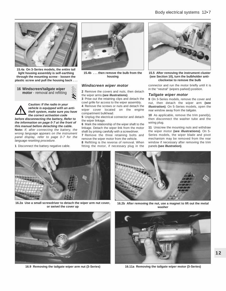
2 Remove the covers and nuts, then detachthe wiper arms (see illustrations).3 Prise out the retaining clips and detach thecowl grille for access to the wiper assembly.4 Remove the screws or nuts and detach thewiper cover located on the enginecompartment bulkhead.5 Unplug the electrical connector and detachthe wiper linkage.6 Mark the relationship of the wiper shaft to thelinkage. Detach the wiper link from the motorshaft by prising carefully with a screwdriver.7 Remove the three retaining bolts andremove the wiper motor from the vehicle.8 Refitting is the reverse of removal. Whenfitting the motor, if necessary plug in the
connector and run the motor briefly until it isin the “neutral” (wipers parked) position.
Tailgate wiper motor9 On 3-Series models, remove the cover andnut, then detach the wiper arm (seeillustration). On 5-Series models, open therear window away from the tailgate.
10 As applicable, remove the trim panel(s),then disconnect the washer tube and thewiring plug.
11 Unscrew the mounting nuts and withdrawthe wiper motor (see illustrations). On 5-Series models, the wiper blade and pivotmechanism may be removed from the rearwindow if necessary after removing the trimpanels (see illustration).
Body electrical systems 12•7
15.5 After removing the instrument cluster(see Section 10), turn the bulbholder anti-
clockwise to remove the bulb
15.4b . . . then remove the bulb from thehousing
15.4a On 3-Series models, the entire taillight housing assembly is self-earthing
through the mounting screw - loosen theplastic screw and pull the housing back . . .
16.11a Removing the tailgate wiper motor (3-Series)
16.2b After removing the nut, use a magnet to lift out the metalwasher
16.2a Use a small screwdriver to detach the wiper arm nut cover,or swivel the cover up
16.9 Removing the tailgate wiper arm nut (3-Series)
12

12 Refitting is a reversal of removal. Whenfitting the motor, if necessary plug in theconnector and run the motor briefly until it isin the “neutral” (wiper parked) position.
17 Heated rear window - check and repair 2
1 The heated rear window consists of anumber of horizontal elements on the glasssurface.2 Small breaks in the element can be repairedwithout removing the rear window.
Check3 Switch on the ignition and the heated rearwindow.4 Place the positive lead of a voltmeter to theheater element nearest to the incoming powersource.5 Wrap a piece of aluminium foil around thenegative lead of the voltmeter on the positiveside of the suspected broken element, andslide it slowly towards the negative side.Watch the voltmeter needle - when it movesfrom zero, you have located the break.
Repair6 Repair the break in the line using a repair kitrecommended specifically for this purpose,such as BMW repair kit No. 81 22 9 (orequivalent). Included in this kit is plasticconductive epoxy. The following paragraphsgive general instructions for this type of repair;follow the instructions supplied with the repairkit if they are different.7 Prior to repairing a break, switch off thecircuit and allow it to cool down for a fewminutes.8 Lightly buff the element area with fine steelwool, then clean it thoroughly.9 Use masking tape to mask off the area ofrepair, leaving a slit to which the epoxy can beapplied.10 Mix the epoxy thoroughly, according tothe instructions on the package.11 Apply the epoxy material to the slit in themasking tape, overlapping the undamagedarea about 20 mm on each end.
12 Allow the repair to cure for 24 hoursbefore removing the tape and using theheated rear window.
18 Supplemental RestraintSystem (SRS) - generalinformation
Later models are equipped with aSupplemental Restraint System (SRS),incorporating an airbag. This system isdesigned to protect the driver from seriousinjury in the event of a head-on or frontalcollision. It consists of an airbag module in thecentre of the steering wheel, two crashsensors mounted on the front inner wingpanels, and a crash safety switch locatedinside the passenger compartment.
The airbag module contains a housingincorporating the airbag and the inflator units.The inflator assembly is mounted on the backof the housing over a hole through which gasis expelled, inflating the bag almost instanta-neously when an electrical signal is sent fromthe system. This signal is carried by a wirewhich is specially wound with several turns,so the signal will be transmitted regardless ofthe steering wheel position.
The SRS system has three sensors: two atthe front, mounted on the inner wing panels(see illustration), and a safety switch locatedinside the passenger compartment. The crashsensors are basically pressure-sensitiveswitches, which complete an electrical circuitduring an impact of sufficient force. Theelectrical signal from the crash sensors is sentto a third sensor, which then completes thecircuit and inflates the airbag.
The module containing the safety switchmonitors the system operation. It checks thesystem every time the vehicle is started,causing the AIRBAG warning light to come on,then go out if the system is operatingcorrectly. If there is a fault in the system, thelight will stay on. If the AIRBAG warning lightdoes stay on, or if it comes on while driving,take the vehicle to your dealer immediately.
19 Cruise control system -description and check 1
The cruise control system maintains vehiclespeed using a vacuum-actuated servo motorlocated in the engine compartment, which isconnected to the throttle linkage by a cable.The system consists of the servo motor,clutch switch, brake switch, control switches,a relay, and associated vacuum hoses.
Because of the complexity of the cruisecontrol system, repair should be left to adealer service department. However, it ispossible for the home mechanic to makesimple checks of the wiring and vacuumconnections for minor faults which can beeasily repaired. These include:a) Inspect the cruise control actuating switches
for broken wires and loose connections.b) Check the cruise control fuse.c) The cruise control system is operated by
vacuum, so it’s critical that all vacuumswitches, hoses and connections aresecure. Check the hoses in the enginecompartment for loose connections,cracks, or obvious vacuum leaks.
20 Central locking system -description and check 2
The central door locking system operatesthe door lock actuators mounted in eachdoor. The system consists of the switches,actuators and associated wiring. Diagnosis islimited to simple checks of the wiringconnections and actuators for minor faultswhich can be easily repaired. These include:a) Check the system fuse and/or circuit
breaker (where applicable).b) Check the switch wires for damage and
loose connections. Check the switchesfor continuity.
c) Remove the door trim panel(s), and checkthe actuator wiring connections to see ifthey’re loose or damaged. Inspect theactuator rods to make sure they aren’t
12•8 Body electrical systems
18.3 The SRS system crash sensors(arrowed) are located in the engine
compartment - check the wiring regularlyfor damage
16.11b Tailgate wiper motor (5-Series) 16.11c Wiper blade and pivot mechanismon the rear window (5-Series)

BK BlackBL BlueBR Brown
GE YellowGN GreenGR Green or Grey
GY GreyOR OrangePK Pink
R RedRS PinkRT Red
SW BlackTN TanV Violet
VI VioletWWhite
WS WhiteY Yellow
Body electrical systems 12•9
12
Colour codes
bent or damaged. The actuator can bechecked by applying battery powermomentarily. A discernible click indicatesthat the solenoid is operating properly.
21 Electric window system -description and check 2
The electric window system operates theelectric motors mounted in the doors whichlower and raise the windows. The systemconsists of the control switches, the motors,window mechanisms (regulators) and
associated wiring. Removal of the motors andregulators is described in Chapter 11.
Diagnosis is usually limited to simplechecks of the wiring connections and motorsfor minor faults which can be easily repaired.These include:a) Check the electric window switches for
broken wires and loose connections.b) Check the electric window fuse/and or
circuit breaker (where applicable).c) Remove the door trim panel(s) and check
the electric window motor wires to see ifthey’re loose or damaged. Inspect thewindow mechanisms for damage whichcould cause binding.
22 Wiring diagrams - general information
Since it isn’t possible to include all wiringdiagrams for every model year covered by thismanual, the following diagrams are those thatare typical and most commonly needed.
Prior to checking any circuit, check thefuses and circuit breakers to make sure they’rein good condition. Make sure the battery isfully charged and check the cable connections(see Chapter 1). Make sure all connectors areclean, with no broken or loose terminals.
12•10 Wiring diagrams
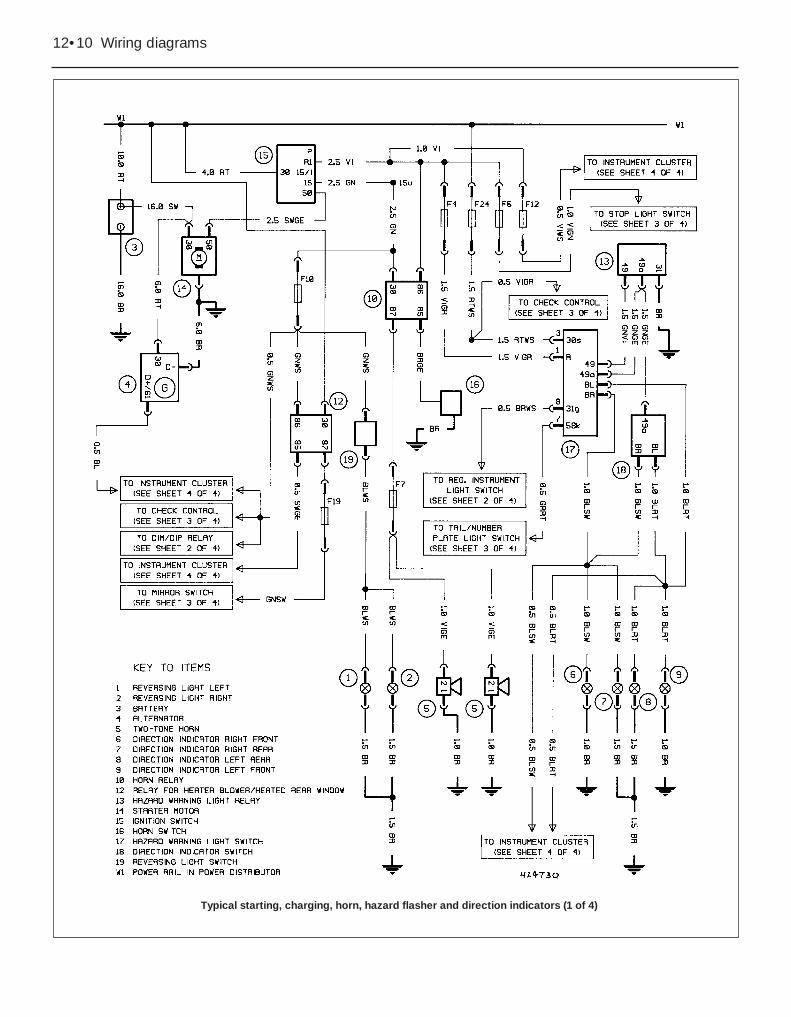
Typical starting, charging, horn, hazard flasher and direction indicators (1 of 4)

Wiring diagrams 12•11
12Typical headlights/foglights and interior lights (2 of 4)

12•12 Wiring diagrams
Typical check control, electric mirrors, stop and parking light (3 of 4)

Wiring diagrams 12•13
12
Typical instrument cluster and cigar lighter (4 of 4)
12•14 Wiring diagrams
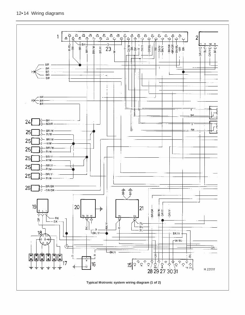
Typical Motronic system wiring diagram (1 of 2)
Wiring diagrams 12•15
12
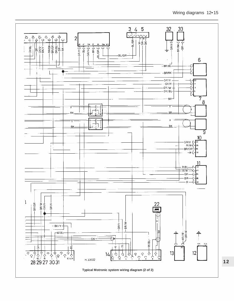
Typical Motronic system wiring diagram (2 of 2)

12•16 Wiring diagrams
Key to Motronic engine control system wiring diagram
Key to cruise control system wiring diagram
Wiring diagrams 12•17
12
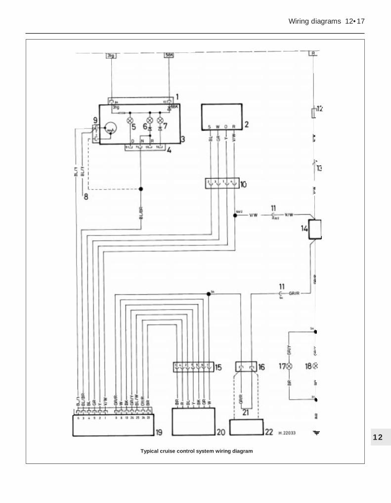
Typical cruise control system wiring diagram

12•18 Wiring diagrams
Typical wiring diagram for the central locking, burglar alarm, on-board computer, additional heater and digital clock (1 of 2)
Wiring diagrams 12•19
12
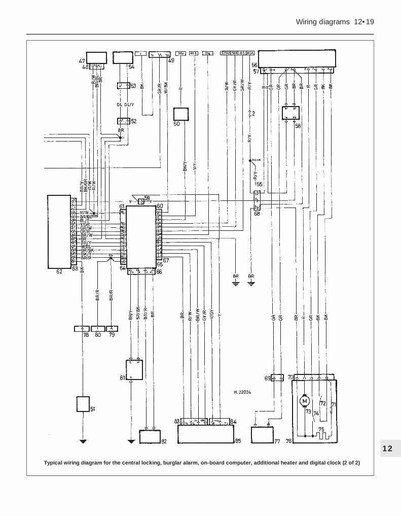
Typical wiring diagram for the central locking, burglar alarm, on-board computer, additional heater and digital clock (2 of 2)
12•20 Wiring diagrams
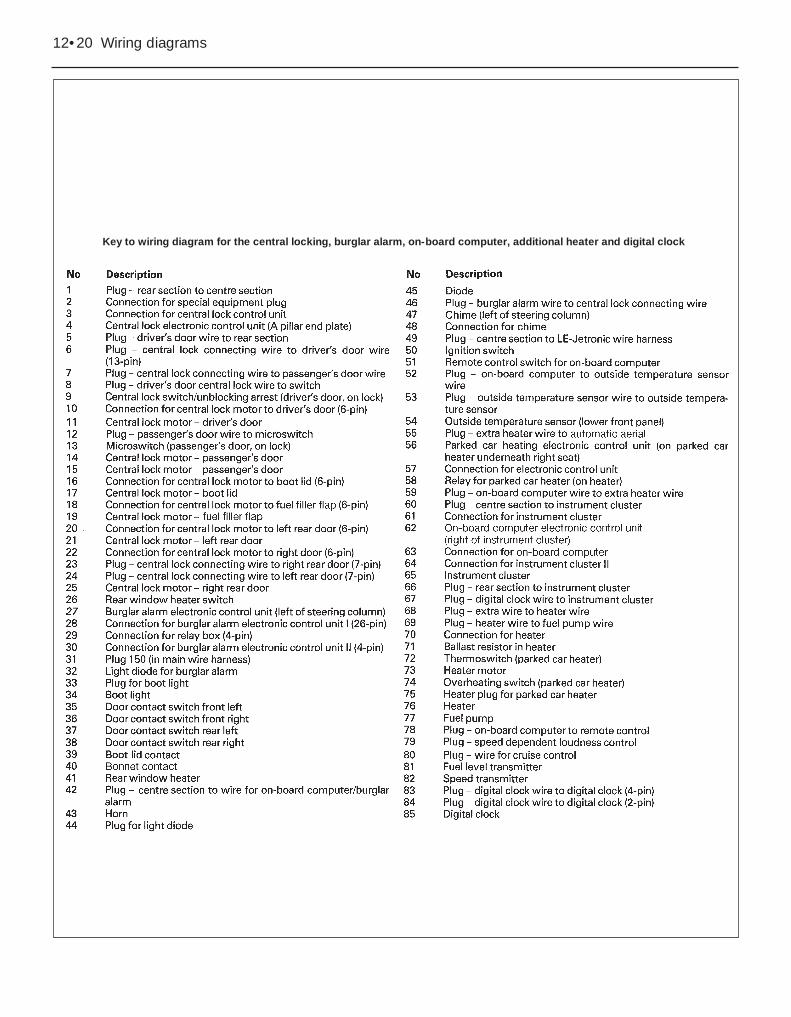
Key to wiring diagram for the central locking, burglar alarm, on-board computer, additional heater and digital clock
Wiring diagrams 12•21
12
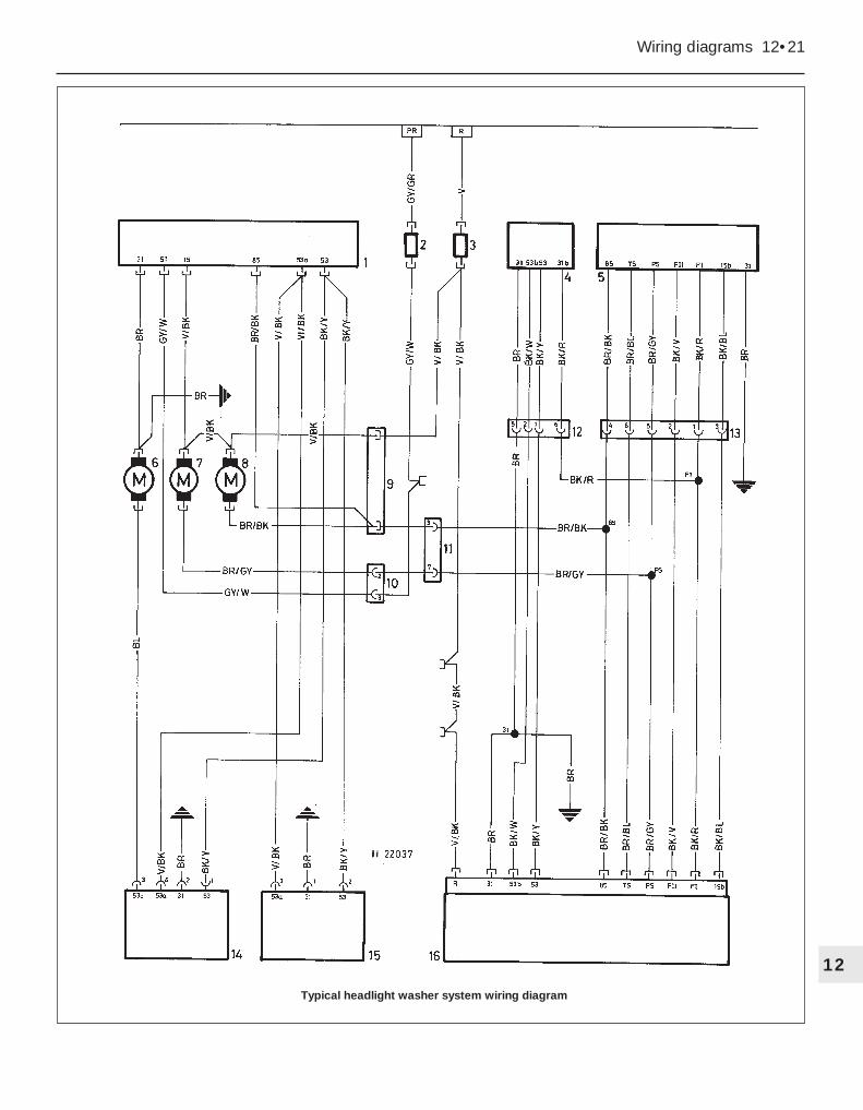
Typical headlight washer system wiring diagram
12•22 Wiring diagrams
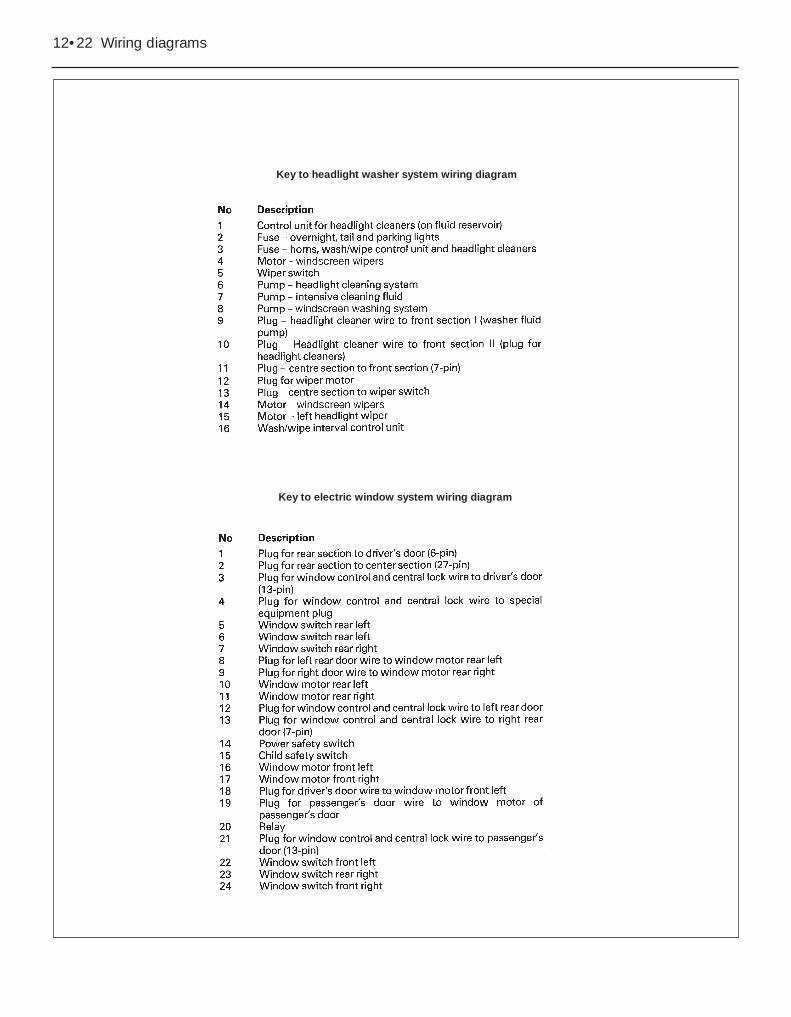
Key to electric window system wiring diagram
Key to headlight washer system wiring diagram

Wiring diagrams 12•23
12
Typical electric window system wiring diagram
12•24 Wiring diagrams
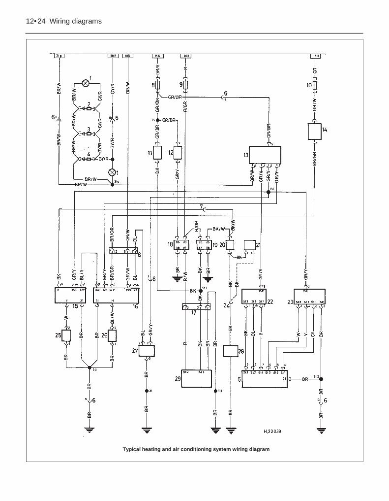
Typical heating and air conditioning system wiring diagram

Wiring diagrams 12•25
12
Key to wiring diagram for heated seats
Key to air conditioning system wiring diagram

12•26 Wiring diagrams
Typical heated seats wiring diagram
Wiring diagrams 12•27
12
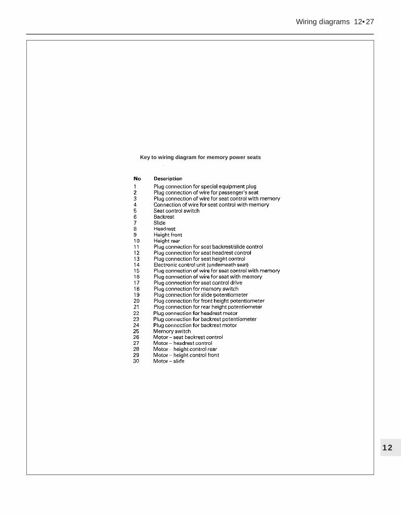
Key to wiring diagram for memory power seats
12•28 Wiring diagrams
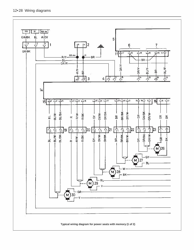
Typical wiring diagram for power seats with memory (1 of 2)
Wiring diagrams 12•29
12
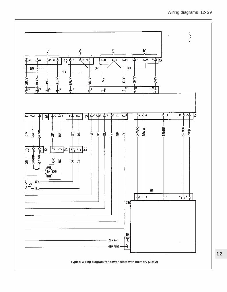
Typical wiring diagram for power seats with memory (2 of 2)
12•30 Wiring diagrams
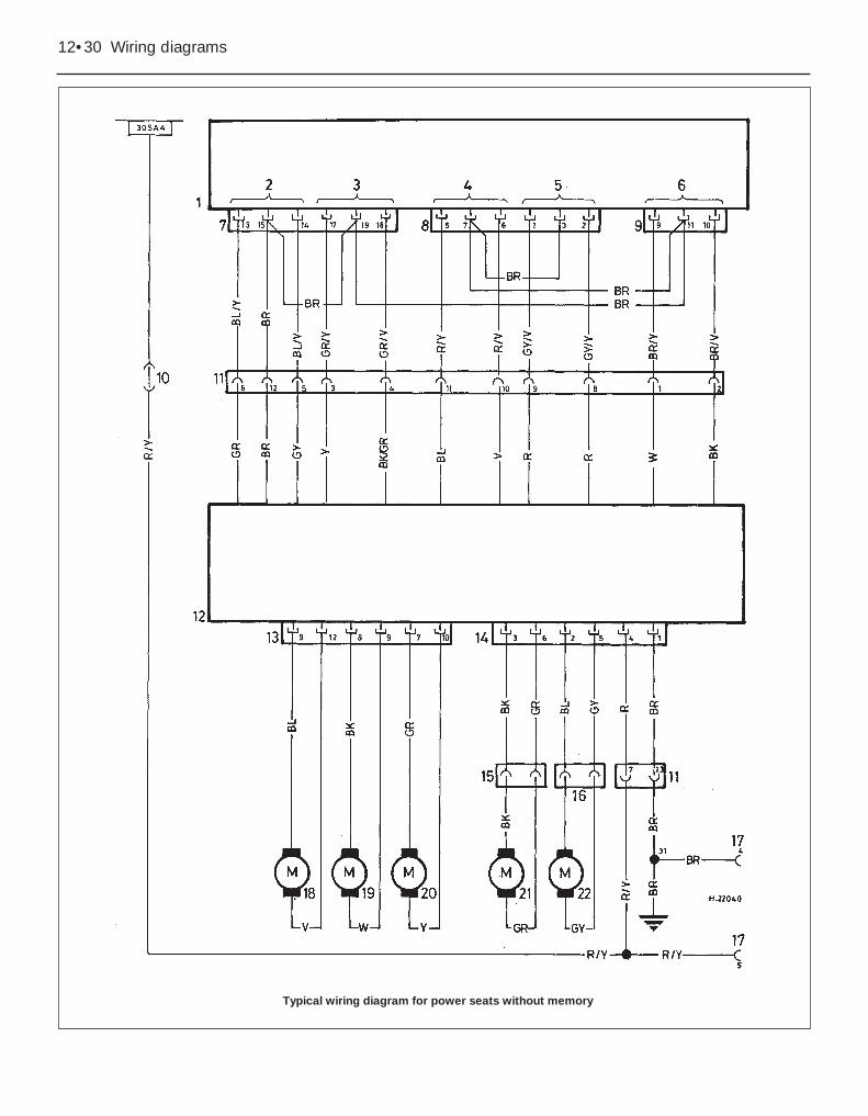
Typical wiring diagram for power seats without memory

Wiring diagrams 12•31
12
Key to wiring diagram for power seats without memory
Key to radio wiring diagram

12•32 Wiring diagrams
Typical radio wiring diagram – early models shown
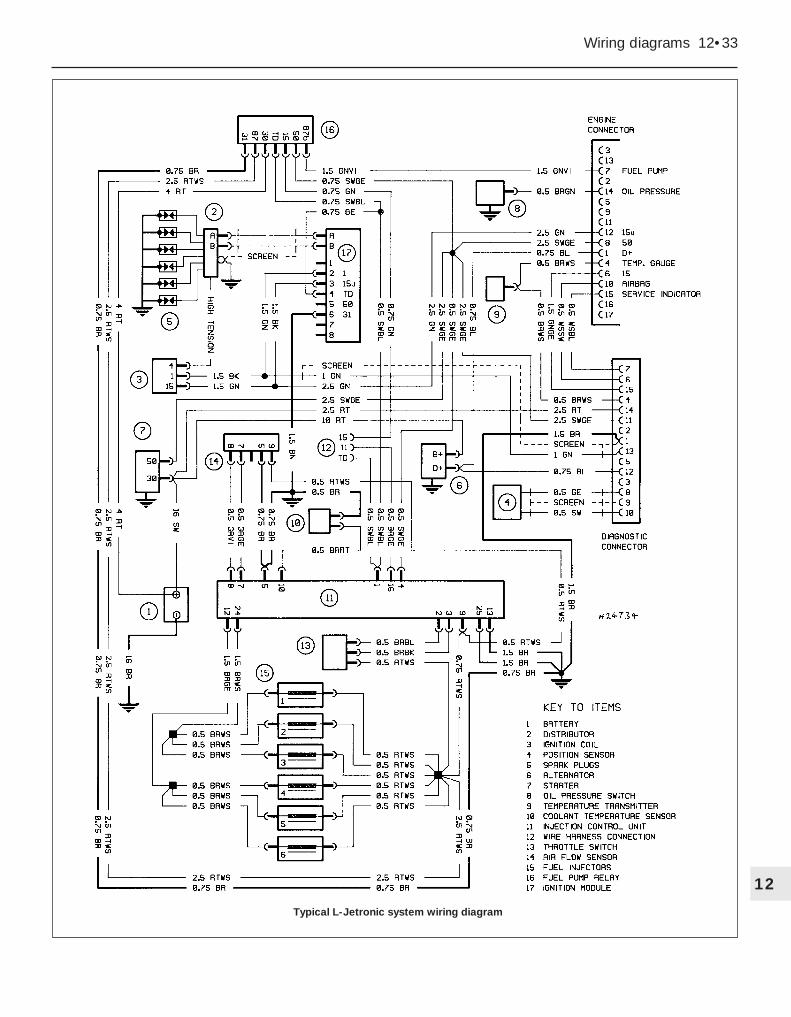
Wiring diagrams 12•33
12
Typical L-Jetronic system wiring diagram