bulletin 140m circuit breakers for motor - rs...
TRANSCRIPT

SlimlineSolutionsfor MotorManagement
The New MCS Circuit BreakersBulletin 140M
Copyright 1999 Rockwell Automation, Printed in SwitzerlandPublication 0140M-CA001A-EN-P July 1999
Slimline Solutions Lead to an New Era inMotor Management
Size 1
Size 2
Size 3
Size 1
Size 2
Size 3
Size 1
Size 2
Size 3
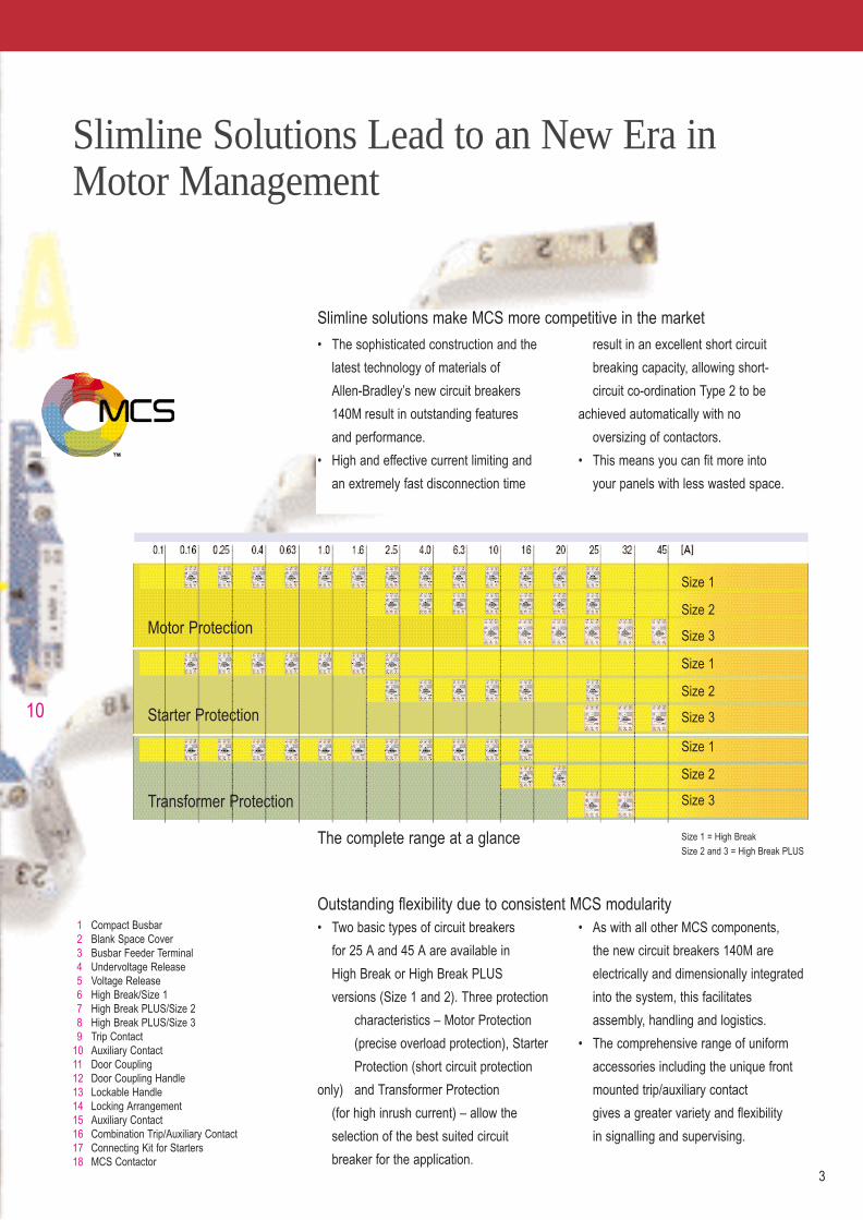
Size 1 = High Break
Size 2 and 3 = High Break PLUS
Motor Protection
Starter Protection
Transformer Protection
2 3
Slimline solutions make MCS more competitive in the market
� The sophisticated construction and the
latest technology of materials of
Allen-Bradley�s new circuit breakers
140M result in outstanding features
and performance.
� High and effective current limiting and
an extremely fast disconnection time
result in an excellent short circuit
breaking capacity, allowing short-
circuit co-ordination Type 2 to be
achieved automatically with no
oversizing of contactors.
� This means you can fit more into
your panels with less wasted space.
Outstanding flexibility due to consistent MCS modularity� Two basic types of circuit breakers
for 25 A and 45 A are available in
High Break or High Break PLUS
versions (Size 1 and 2). Three protection
characteristics � Motor Protection
(precise overload protection), Starter
Protection (short circuit protection
only) and Transformer Protection
(for high inrush current) � allow the
selection of the best suited circuit
breaker for the application.
� As with all other MCS components,
the new circuit breakers 140M are
electrically and dimensionally integrated
into the system, this facilitates
assembly, handling and logistics.
� The comprehensive range of uniform
accessories including the unique front
mounted trip/auxiliary contact
gives a greater variety and flexibility
in signalling and supervising.
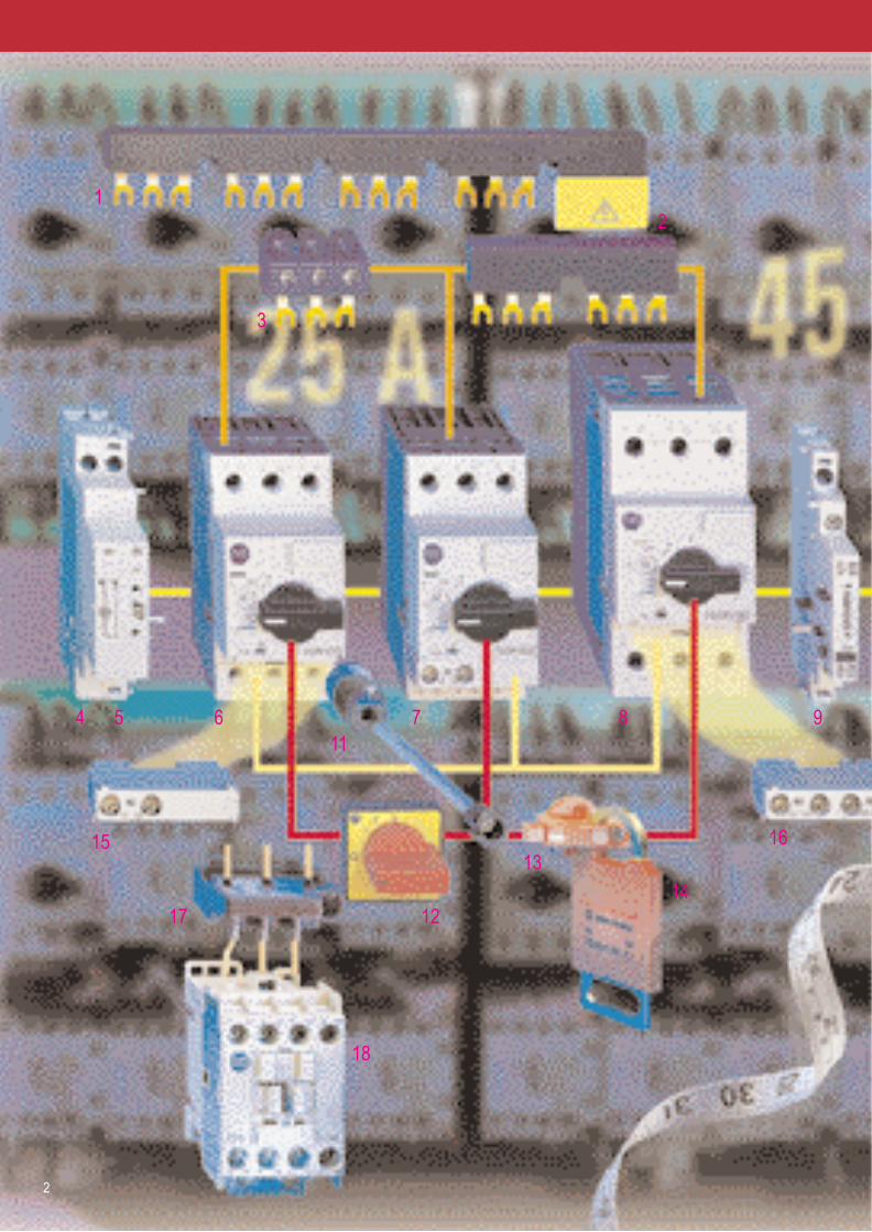
The complete range at a glance
1 Compact Busbar2 Blank Space Cover3 Busbar Feeder Terminal4 Undervoltage Release5 Voltage Release6 High Break/Size 17 High Break PLUS/Size 28 High Break PLUS/Size 39 Trip Contact
10 Auxiliary Contact11 Door Coupling12 Door Coupling Handle13 Lockable Handle14 Locking Arrangement15 Auxiliary Contact16 Combination Trip/Auxiliary Contact17 Connecting Kit for Starters18 MCS Contactor
12
3
4 5
15
17
18
6 7 8 9
16
1011
1214
13
Slimline Solutions Lead to an New Era inMotor Management
Size 1
Size 2
Size 3
Size 1
Size 2
Size 3
Size 1
Size 2
Size 3
Size 1 = High Break
Size 2 and 3 = High Break PLUS
Motor Protection
Starter Protection
Transformer Protection
2 3
Slimline solutions make MCS more competitive in the market
� The sophisticated construction and the
latest technology of materials of
Allen-Bradley�s new circuit breakers
140M result in outstanding features
and performance.
� High and effective current limiting and
an extremely fast disconnection time
result in an excellent short circuit
breaking capacity, allowing short-
circuit co-ordination Type 2 to be
achieved automatically with no
oversizing of contactors.
� This means you can fit more into
your panels with less wasted space.
Outstanding flexibility due to consistent MCS modularity� Two basic types of circuit breakers
for 25 A and 45 A are available in
High Break or High Break PLUS
versions (Size 1 and 2). Three protection
characteristics � Motor Protection
(precise overload protection), Starter
Protection (short circuit protection
only) and Transformer Protection
(for high inrush current) � allow the
selection of the best suited circuit
breaker for the application.
� As with all other MCS components,
the new circuit breakers 140M are
electrically and dimensionally integrated
into the system, this facilitates
assembly, handling and logistics.
� The comprehensive range of uniform
accessories including the unique front
mounted trip/auxiliary contact
gives a greater variety and flexibility
in signalling and supervising.
The complete range at a glance
1 Compact Busbar2 Blank Space Cover3 Busbar Feeder Terminal4 Undervoltage Release5 Voltage Release6 High Break/Size 17 High Break PLUS/Size 28 High Break PLUS/Size 39 Trip Contact
10 Auxiliary Contact11 Door Coupling12 Door Coupling Handle13 Lockable Handle14 Locking Arrangement15 Auxiliary Contact16 Combination Trip/Auxiliary Contact17 Connecting Kit for Starters18 MCS Contactor
12
3
4 5
15
17
18
6 7 8 9
16
1011
1214
13

4 5
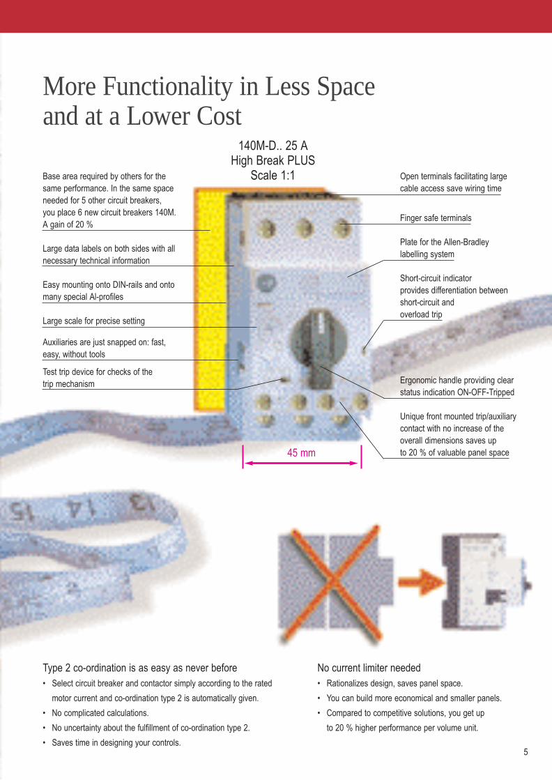
Base area required by others for the same performance. In the same spaceneeded for 5 other circuit breakers, you place 6 new circuit breakers 140M. A gain of 20 %
Large data labels on both sides with all necessary technical information
Easy mounting onto DIN-rails and ontomany special Al-profiles
Large scale for precise setting
Auxiliaries are just snapped on: fast, easy, without tools
Test trip device for checks of the trip mechanism
Open terminals facilitating large cable access save wiring time
Finger safe terminals
Plate for the Allen-Bradley labelling system
Short-circuit indicator provides differentiation between short-circuit and overload trip
Ergonomic handle providing clearstatus indication ON-OFF-Tripped
Unique front mounted trip/auxiliarycontact with no increase of the overall dimensions saves up to 20 % of valuable panel space
✔ Protection of installation✔ Protection of circuits✔ Motor protection✔ Starter protection✔ Transformer protection✔ Wide range of ambient
temperature compensation✔ Phase failure protection✔ High phase loss sensitivity✔ Easy coordination to back-up
selective circuit breaker
The breaking champion� The new circuit breakers 140M set new standards in breaking
capacity and current limiting. This results in these benefits:➤ No back-up fuses➤ No current limiters➤ No oversizing of contactors.
� The new circuit breakers 140M can be installed even closer to supply transformers.
The money saving champion� With the new circuit breakers 140M you get a superior
price/performance ratio compared to other solutions.� No oversizing of contactors necessary, this makes starters
more economical.� No need for costly integrated starter solutions thanks to the
consistent modular concept.� Compact starters lead to smaller, more economical control
cabinets and panels.
No current limiter needed� Rationalizes design, saves panel space.
� You can build more economical and smaller panels.
� Compared to competitive solutions, you get up
to 20 % higher performance per volume unit.
More Functionality in Less Space and at a Lower Cost
45 mm
140M-D.. 25 A High Break PLUS
Scale 1:1
Type 2 co-ordination is as easy as never before� Select circuit breaker and contactor simply according to the rated
motor current and co-ordination type 2 is automatically given.
� No complicated calculations.
� No uncertainty about the fulfillment of co-ordination type 2.
� Saves time in designing your controls.
Comparison Type « 2 » co-ordinated
Rockwell Automation Conventional solution Integrated 140M with oversizing solutions
400 V
Breaking
Capacity Price
Rated operat. current Ie [A]
140M-F / Size 3
140M-D / Size 2
140M-C / Size 1
4 5
Base area required by others for the same performance. In the same spaceneeded for 5 other circuit breakers, you place 6 new circuit breakers 140M. A gain of 20 %
Large data labels on both sides with all necessary technical information
Easy mounting onto DIN-rails and ontomany special Al-profiles
Large scale for precise setting
Auxiliaries are just snapped on: fast, easy, without tools
Test trip device for checks of the trip mechanism
Open terminals facilitating large cable access save wiring time
Finger safe terminals
Plate for the Allen-Bradley labelling system
Short-circuit indicator provides differentiation between short-circuit and overload trip
Ergonomic handle providing clearstatus indication ON-OFF-Tripped
Unique front mounted trip/auxiliarycontact with no increase of the overall dimensions saves up to 20 % of valuable panel space
✔ Protection of installation✔ Protection of circuits✔ Motor protection✔ Starter protection✔ Transformer protection✔ Wide range of ambient
temperature compensation✔ Phase failure protection✔ High phase loss sensitivity✔ Easy coordination to back-up
selective circuit breaker
The breaking champion� The new circuit breakers 140M set new standards in breaking
capacity and current limiting. This results in these benefits:➤ No back-up fuses➤ No current limiters➤ No oversizing of contactors.
� The new circuit breakers 140M can be installed even closer to supply transformers.
The money saving champion� With the new circuit breakers 140M you get a superior
price/performance ratio compared to other solutions.� No oversizing of contactors necessary, this makes starters
more economical.� No need for costly integrated starter solutions thanks to the
consistent modular concept.� Compact starters lead to smaller, more economical control
cabinets and panels.
No current limiter needed� Rationalizes design, saves panel space.
� You can build more economical and smaller panels.
� Compared to competitive solutions, you get up
to 20 % higher performance per volume unit.
More Functionality in Less Space and at a Lower Cost
45 mm
140M-D.. 25 A High Break PLUS
Scale 1:1
Type 2 co-ordination is as easy as never before� Select circuit breaker and contactor simply according to the rated
motor current and co-ordination type 2 is automatically given.
� No complicated calculations.
� No uncertainty about the fulfillment of co-ordination type 2.
� Saves time in designing your controls.
Comparison Type « 2 » co-ordinated
Rockwell Automation Conventional solution Integrated 140M with oversizing solutions
400 V
Breaking
Capacity Price
Rated operat. current Ie [A]
140M-F / Size 3
140M-D / Size 2
140M-C / Size 1
6 7
Smarter Actuation and Status IndicationEnhance Operational Safety and Control
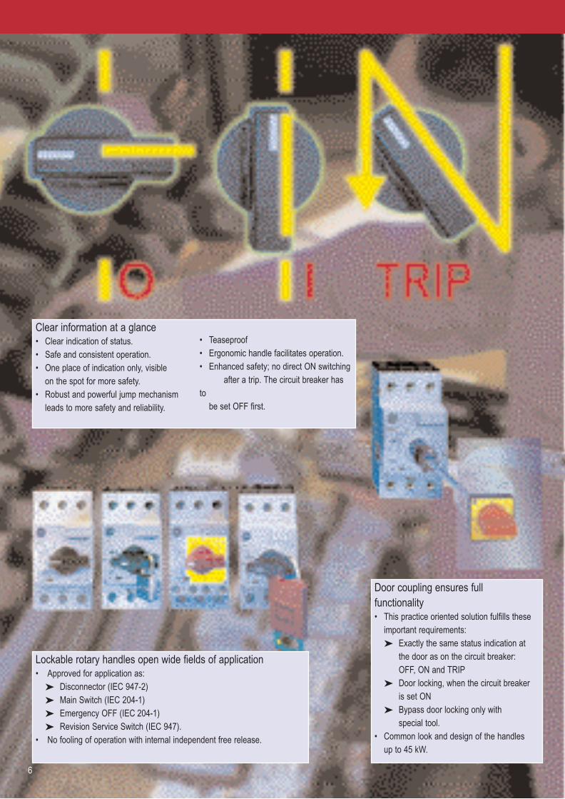
Clear information at a glance� Clear indication of status. � Safe and consistent operation.� One place of indication only, visible
on the spot for more safety.� Robust and powerful jump mechanism
leads to more safety and reliability.
� Teaseproof� Ergonomic handle facilitates operation.� Enhanced safety; no direct ON switching
after a trip. The circuit breaker hasto
be set OFF first.
Lockable rotary handles open wide fields of application� Approved for application as:
➤ Disconnector (IEC 947-2)➤ Main Switch (IEC 204-1)➤ Emergency OFF (IEC 204-1)➤ Revision Service Switch (IEC 947).
� No fooling of operation with internal independent free release.
Door coupling ensures full functionality� This practice oriented solution fulfills these
important requirements:➤ Exactly the same status indication at
the door as on the circuit breaker: OFF, ON and TRIP
➤ Door locking, when the circuit breaker is set ON
➤ Bypass door locking only with special tool.
� Common look and design of the handles up to 45 kW.
Allen-Bradley 140M
I ON
O OFF
Other Circuit breakers
I ON
O OFF
Jump mechanism guarantees clear switching status� The jump mechanism ensures a very fast closing or opening of the contacts,
the circuit breaker is either OFF or ON, 140M is teaseproof.
Manipulation made impossible� The anti tamper cover prevents
unauthorized change of the operational current setting.
� Clear current setting scale, level with the front to avoid unintentional changes.
More indication possibilities� All different operation and fault
conditions can be transmitted by auxiliary contacts.
� The 140M offers more auxiliary combinations than others:➤ Front mounting: 6 variations➤ Side mounting: 8 variations.
Undervoltage /voltage release� Undervoltage release� Undervoltage release with
2 early make contacts� Voltage release
Front mounting trip /auxiliary contacts� 1 N.O. trip / 1 N.O. aux.� 1 N.O. trip / 1 N.C. aux.
Side mounting trip contacts
� 1 N.O. trip / 1 N.O. trip short-circuit only
� 1 N.O. trip / 1 N.C. trip short-circuit only
� 1 N.C. trip / 1 N.O. trip short-circuit only
� 1 N.C. trip /1 N.C. trip short-circuit only
� 1 N.O. trip short-circuit only / 1 N.C. trip short-circuit only
Side mounting auxiliary contacts� 2 N.O.� 2 N.C.� 1 N.O. / 1 N.C.
Front mounting auxiliary contacts� 1 N.O.� 1 N.C.� 1 N.O. / 1 N.C.� 2 N.O.
Short-circuit indicator� A red flag on the I» window shows that a
short-circuit has occurred. This allows the immediale distinction between a short-circuit and a overload trip.
� No waste of time in troubleshooting.

6 7
Smarter Actuation and Status IndicationEnhance Operational Safety and Control
Clear information at a glance� Clear indication of status. � Safe and consistent operation.� One place of indication only, visible
on the spot for more safety.� Robust and powerful jump mechanism
leads to more safety and reliability.
� Teaseproof� Ergonomic handle facilitates operation.� Enhanced safety; no direct ON switching
after a trip. The circuit breaker hasto
be set OFF first.
Lockable rotary handles open wide fields of application� Approved for application as:
➤ Disconnector (IEC 947-2)➤ Main Switch (IEC 204-1)➤ Emergency OFF (IEC 204-1)➤ Revision Service Switch (IEC 947).
� No fooling of operation with internal independent free release.
Door coupling ensures full functionality� This practice oriented solution fulfills these
important requirements:➤ Exactly the same status indication at
the door as on the circuit breaker: OFF, ON and TRIP
➤ Door locking, when the circuit breaker is set ON
➤ Bypass door locking only with special tool.
� Common look and design of the handles up to 45 kW.
Allen-Bradley 140M
I ON
O OFF
Other Circuit breakers
I ON
O OFF
Jump mechanism guarantees clear switching status� The jump mechanism ensures a very fast closing or opening of the contacts,
the circuit breaker is either OFF or ON, 140M is teaseproof.
Manipulation made impossible� The anti tamper cover prevents
unauthorized change of the operational current setting.
� Clear current setting scale, level with the front to avoid unintentional changes.
More indication possibilities� All different operation and fault
conditions can be transmitted by auxiliary contacts.
� The 140M offers more auxiliary combinations than others:➤ Front mounting: 6 variations➤ Side mounting: 8 variations.
Undervoltage /voltage release� Undervoltage release� Undervoltage release with
2 early make contacts� Voltage release
Front mounting trip /auxiliary contacts� 1 N.O. trip / 1 N.O. aux.� 1 N.O. trip / 1 N.C. aux.
Side mounting trip contacts
� 1 N.O. trip / 1 N.O. trip short-circuit only
� 1 N.O. trip / 1 N.C. trip short-circuit only
� 1 N.C. trip / 1 N.O. trip short-circuit only
� 1 N.C. trip /1 N.C. trip short-circuit only
� 1 N.O. trip short-circuit only / 1 N.C. trip short-circuit only
Side mounting auxiliary contacts� 2 N.O.� 2 N.C.� 1 N.O. / 1 N.C.
Front mounting auxiliary contacts� 1 N.O.� 1 N.C.� 1 N.O. / 1 N.C.� 2 N.O.
Short-circuit indicator� A red flag on the I» window shows that a
short-circuit has occurred. This allows the immediale distinction between a short-circuit and a overload trip.
� No waste of time in troubleshooting.

8 9
Compact Dimensions and Easy HandlingSave Panel Space and Installation Time
Compact mounting allows more com-pact panels� Compact mounting side by side saves
valuable panel space. No gaps in
between required.
� Lowest arcing safety space requirements
allow denser layouts.
� No current limiters needed anymore.
� No increase in width thanks to the
unique front mounted trip indicator /
auxiliary contact. This saves 20 % of
panel space.
� With the new circuit breaker 140M you
get the most compact solutions.
No gapsrequired
Compactwiringlinks
Minimal arcing safetyspace required
Faster and easier mounting� Snaps safely without fixing clip onto
standard DIN-rails.
� Complete starter assemblies can be snap-
ped on only one DIN-rail. No mounting
distance required behind the rail.
Vertical mounting saves space� Vertical mounting allows the optimal
positioning of the wiring channels close
to the components.
Auxiliaries easily fitted� All auxiliaries are added simply by hand.
No tools required.
� Unparallelled easy fitting.
� Simple changing even when mounted.
Built for faster wiring� Only one screwdriver (Pozidrive No. 2 or blade type No. 3)
needed for all new 140M components.
� Screw driver guiding shafts speed up connection time.
� Delivered with open terminal screws for immediate wiring.
Better terminals save wiring time� Easy fitting of large cross sectional or combinations
of conductors.
� Dual terminal technology offers more wiring flexibility.
� Insertion funnels and embeded terminals guarantee
increased finger protection.
The smart concept for fast panel building� Complete range of compact busbars for easy wiring.� Wiring sets facilitate the connection of circuit breakers
and contactors.
� Wiring sets and busbars are inevitable for building assemblies in compliance with the new regulations (EN 60 439).
� With all the wiring accessories you can build assemblies fast, easy and safe.

10
Any Other Circuit Breaker is a Waste of Space
Space needed by others
Your gain in panel space
Achieves Type 2
co-ordination with
NO OVERSIZINGof contactors
Starter 22 kW 43 A
Motor Management for flexible solutions� Motor Management is the way of Rockwell Automation to
flexible solution for the industrial automation.� The core of Motor Management is the MCS � Modular Control
System � and the new circuit breakers 140M are a fundamental part of MCS and follow consistently the ideas of MCS:➤ All components are designed for electrical and dimensional
co-ordination which makes assembly very easy➤ Consistent 9 mm spacing simplifies planning and installation.
� In combination with the DeviceNet Starter Auxiliary Module, 140M are easily integrated in modern networks.
11
Type 2 with no oversizing� The new circuit-breakers 140M achieve
Type 2 co-ordination automatically at 400V:➤ Determine the rated motor current➤ Select the type of 140M and 100-C-
contactor accordingly.� The fast opening contacts and the high
current limiting qualities of the 140M make Type 2 co-ordination possible ➤ without current limiters➤ with no oversizing
of contactors.� The result are slimmer, more compact
starters with less wasted space and with a superior price/performance ratio.
The benefits of Type 2� For today's assemblies in compliance
with the regulations, Type 2 co-ordina-tion is a necessity. Type 2 is synonymous for these benefits:➤ Reliable protection for people
and plant➤ The starter is still fully operational
after a short-circuit➤ The installation or the plant is
back in operation quickly➤ Minimized downtime and
minimized loss of production➤ Enhanced safety➤ Improved reliability.
What is co-ordination Type 2?� According to IEC 947-4-1, co-ordination
Type 2 is achieved when these condi-tions are fulfilled:
➤ The contactor or the starter must not endanger persons or systems in the event of a short circuit
➤ The contactor or the starter must be suitable for further use
➤ No damage to the overload relay or other parts may occur with the exception of welding of the contactoror starter contacts provided that these can be easily separated with-out significant deformation (such as with a screwdriver).

Your Best Choice.
Developed for the world marketplace� The new circuit breakers 140M are
developed and manufactured in
Europe for the tough requirements of
the world market.
� The components fulfill the international
standards IEC 947-1/2/4. This allows
applications around the world.
� In North America, the devices can be
used as Manual Motor Starter in Group
Installations according UL 508.
The approval for new UL 508 Type E
Combination Starter is under preparation.
A top product from a global leader� Allen-Bradley is the premier brand of
Rockwell Automation, a global leader;
No. 1 in North America, and Top 3
world wide.
� Rockwell Automation is a global
company committed to serving needs
locally with 620 sales- and support
offices in more than 80 countries.
� 5�600 distributors, system integrators
and agents worldwide guarantee
assistance and service around the globe.
Winning the future with excellence� The new circuit breakers 140M set
benchmarks in performance but also in
environmental excellence.
� The development and the production of
the 140M is made under a the very strin-
gent quality management system accord-
ing ISO 9001. This maintains the
performance of the 140M consistently
on the very high specified level.
� The environmental management system
according to ISO 14001 assures an
ecological production and environment
friendly materials.
12

Rockwell Automation 13
Bulletin 140MCircuit Breakers
111
Circuit BreakersBulletin 140M
• Power Range0.1...45 A
• Various Protection Characteristics
• Easily Recognizable State of Operation
• High Current Limiting• High Switching Capacity
ContentsDescription Page Description PageProduct Selection
Motor protection . . . . . . . . . . . . . . . . . . . . . . . . . . . . . . . . . . . . . 14
Short-circuit protection for starters . . . . . . . . . . . . . . . . . . . . . . . 15
Transformer protection . . . . . . . . . . . . . . . . . . . . . . . . . . . . . . . . 16
Compact starters . . . . . . . . . . . . . . . . . . . . . . . . . . . . . . . . . . . . 17
Accessories. . . . . . . . . . . . . . . . . . . . . . . . . . . . . . . . . . . . . . . . . . 18
Technical Information
Performance . . . . . . . . . . . . . . . . . . . . . . . . . . . . . . . . . . . . . . . . 21
General . . . . . . . . . . . . . . . . . . . . . . . . . . . . . . . . . . . . . . . . . . . . 27
Standards and Approvals . . . . . . . . . . . . . . . . . . . . . . . . . . . . . . 28
Weight . . . . . . . . . . . . . . . . . . . . . . . . . . . . . . . . . . . . . . . . . . . . . 29
Accessories. . . . . . . . . . . . . . . . . . . . . . . . . . . . . . . . . . . . . . . . . 28
Short-circuit coordination . . . . . . . . . . . . . . . . . . . . . . . . . . . . . . 30
Dimensions . . . . . . . . . . . . . . . . . . . . . . . . . . . . . . . . . . . . . . . . . . 32
Bulletin 140MCircuit Breakers
14 Rockwell Automation
Product Selection
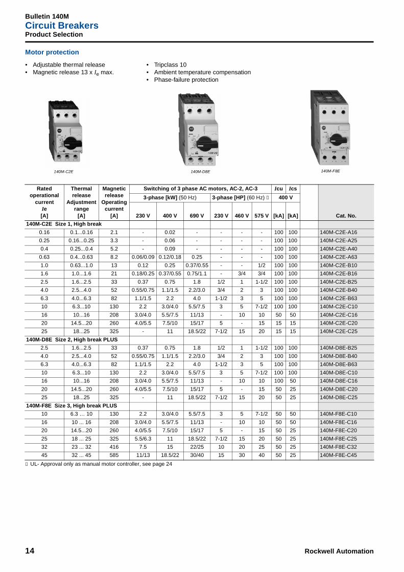
Motor protection
➊ UL- Approval only as manual motor controller, see page 24
Ratedoperational
currentIe[A]
Thermalrelease
Adjustmentrange
[A]
Magneticrelease
Operatingcurrent
[A]
Switching of 3 phase AC motors, AC-2, AC-3 Icu Ics
Cat. No.
3-phase [kW] (50 Hz) 3-phase [HP] (60 Hz) ➊ 400 V
230 V 400 V 690 V 230 V 460 V 575 V [kA] [kA]
140M-C2E Size 1, High break
0.16 0.1...0.16 2.1 - 0.02 - - - - 100 100 140M-C2E-A16
0.25 0.16...0.25 3.3 - 0.06 - - - - 100 100 140M-C2E-A25
0.4 0.25...0.4 5.2 - 0.09 - - - - 100 100 140M-C2E-A40
0.63 0.4...0.63 8.2 0.06/0.09 0.12/0.18 0.25 - - - 100 100 140M-C2E-A63
1.0 0.63...1.0 13 0.12 0.25 0.37/0.55 - - 1/2 100 100 140M-C2E-B10
1.6 1.0...1.6 21 0.18/0.25 0.37/0.55 0.75/1.1 - 3/4 3/4 100 100 140M-C2E-B16
2.5 1.6...2.5 33 0.37 0.75 1.8 1/2 1 1-1/2 100 100 140M-C2E-B25
4.0 2.5...4.0 52 0.55/0.75 1.1/1.5 2.2/3.0 3/4 2 3 100 100 140M-C2E-B40
6.3 4.0...6.3 82 1.1/1.5 2.2 4.0 1-1/2 3 5 100 100 140M-C2E-B63
10 6.3...10 130 2.2 3.0/4.0 5.5/7.5 3 5 7-1/2 100 100 140M-C2E-C10
16 10...16 208 3.0/4.0 5.5/7.5 11/13 - 10 10 50 50 140M-C2E-C16
20 14.5...20 260 4.0/5.5 7.5/10 15/17 5 - 15 15 15 140M-C2E-C20
25 18...25 325 - 11 18.5/22 7-1/2 15 20 15 15 140M-C2E-C25
140M-D8E Size 2, High break PLUS
2.5 1.6...2.5 33 0.37 0.75 1.8 1/2 1 1-1/2 100 100 140M-D8E-B25
4.0 2.5...4.0 52 0.55/0.75 1.1/1.5 2.2/3.0 3/4 2 3 100 100 140M-D8E-B40
6.3 4.0...6.3 82 1.1/1.5 2.2 4.0 1-1/2 3 5 100 100 140M-D8E-B63
10 6.3...10 130 2.2 3.0/4.0 5.5/7.5 3 5 7-1/2 100 100 140M-D8E-C10
16 10...16 208 3.0/4.0 5.5/7.5 11/13 - 10 10 100 50 140M-D8E-C16
20 14.5...20 260 4.0/5.5 7.5/10 15/17 5 - 15 50 25 140M-D8E-C20
25 18...25 325 - 11 18.5/22 7-1/2 15 20 50 25 140M-D8E-C25
140M-F8E Size 3, High break PLUS
10 6.3 … 10 130 2.2 3.0/4.0 5.5/7.5 3 5 7-1/2 50 50 140M-F8E-C10
16 10 ... 16 208 3.0/4.0 5.5/7.5 11/13 - 10 10 50 50 140M-F8E-C16
20 14.5...20 260 4.0/5.5 7.5/10 15/17 5 - 15 50 25 140M-F8E-C20
25 18 ... 25 325 5.5/6.3 11 18.5/22 7-1/2 15 20 50 25 140M-F8E-C25
32 23 ... 32 416 7.5 15 22/25 10 20 25 50 25 140M-F8E-C32
45 32 ... 45 585 11/13 18.5/22 30/40 15 30 40 50 25 140M-F8E-C45
140M-C2E 140M-D8E 140M-F8E
• Adjustable thermal release• Magnetic release 13 x Ie max.
• Tripclass 10• Ambient temperature compensation• Phase-failure protection

Rockwell Automation 15
Bulletin 140MCircuit Breakers
Product Selection
Short-circuit protection for starters 1
➊ UL- Approval only as manual motor controller, see page 24
Ratedoperational
currentIe[A]
Thermal release
Adjustment range
[A]
Magnetic release
Operating current
[A]
Switching of 3 phase AC motors, AC-2, AC-3 Icu Ics
Cat. No.
3-phase [kW] (50 Hz) 3-phase [HP] (60 Hz) ➊ 400 V
230 V 400 V 690 V 230 V 460 V 575 V [kA] [kA]
140M-C2N Size 1, High break
0.16 - 2.1 - 0.02 - - - - 100 100 140M-C2N-A16
0.25 - 3.3 - 0.06 - - - - 100 100 140M-C2N-A25
0.4 - 5.2 - 0.09 - - - - 100 100 140M-C2N-A40
0.63 - 8.2 0.06/0.09 0.12/0.18 0.25 - - - 100 100 140M-C2N-A63
1.0 - 13 0.12 0.25 0.37/0.55 - - 1/2 100 100 140M-C2N-B10
1.6 - 20 0.18/0.25 0.37/0.55 0.75/1.1 - 3/4 3/4 100 100 140M-C2N-B16
2.5 - 32 0.37 0.75 1.8 1/2 1 1-1/2 100 100 140M-C2N-B25
140M-D8N Size 2, High break PLUS
2.5 - 32 0.37 0.75 1.8 1/2 1 1-1/2 100 100 140M-D8N-B25
4 - 52 0.55/0.75 1.1/1.5 2.2/3.0 3/4 2 3 100 100 140M-D8N-B40
6.3 - 82 1.1/1.5 2.2 4.0 1-1/2 3 5 100 100 140M-D8N-B63
10 - 130 2.2 3.0/4.0 5.5/7.5 3 5 7-1/2 100 100 140M-D8N-C10
16 - 208 3.0/4.0 5.5/7.5 11/13 - 10 10 100 50 140M-D8N-C16
25 - 325 - 11 18.5/22 7-1/2 15 20 50 25 140M-D8N-C25
140M-F8N Size 3, High break PLUS
25 - 325 5.5/6.3 11 18.5/22 7-1/2 15 20 50 25 140M-F8N-C25
32 - 416 7.5 15 22/25 10 20 25 50 25 140M-F8N-C32
45 - 585 11/13 18.5/22 30/40 15 30 40 50 25 140M-F8N-C45
Utilization categories for alternating current per IEC 947:
AC-2 starting and reversing of slip ring motorsAC-3 starting and disconnecting squirrel cage induction motors
IEC 947-2 performance categories:
Icu Ultimate short-circuit breaking capacitystill operational after testing with O-t-CO
Ics Rated service short-circuit breaking capacitysuitable for normal operation after testing with O-t-CO-t-CO
O = offCO = restart and offt = time delay
140M-C2N 140M-D8N 140M-F8N
• without thermal release• Magnetic release 13 x Ie
Bulletin 140MCircuit Breakers
16 Rockwell Automation
Product Selection
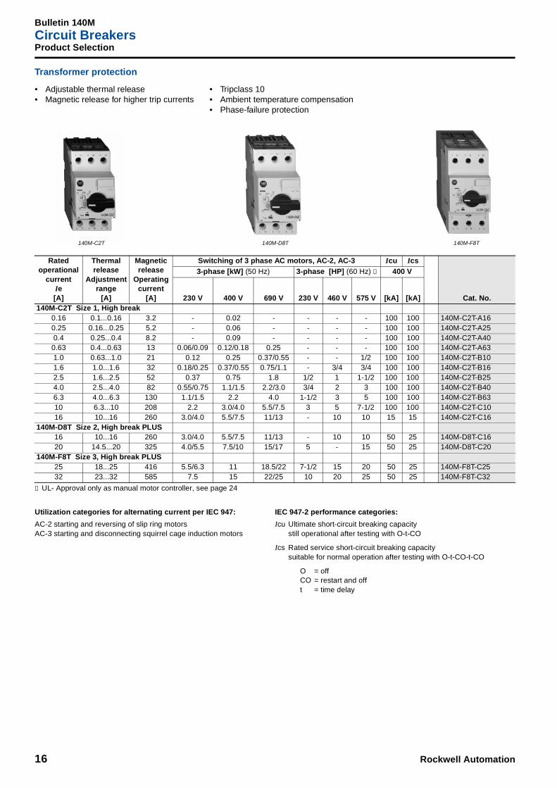
Transformer protection
➊ UL- Approval only as manual motor controller, see page 24
Ratedoperational
currentIe[A]
Thermal release
Adjustment range
[A]
Magnetic release
Operating current
[A]
Switching of 3 phase AC motors, AC-2, AC-3 Icu Ics
Cat. No.
3-phase [kW] (50 Hz) 3-phase [HP] (60 Hz) ➊ 400 V
230 V 400 V 690 V 230 V 460 V 575 V [kA] [kA]140M-C2T Size 1, High break
0.16 0.1...0.16 3.2 - 0.02 - - - - 100 100 140M-C2T-A160.25 0.16...0.25 5.2 - 0.06 - - - - 100 100 140M-C2T-A250.4 0.25...0.4 8.2 - 0.09 - - - - 100 100 140M-C2T-A400.63 0.4...0.63 13 0.06/0.09 0.12/0.18 0.25 - - - 100 100 140M-C2T-A631.0 0.63...1.0 21 0.12 0.25 0.37/0.55 - - 1/2 100 100 140M-C2T-B101.6 1.0...1.6 32 0.18/0.25 0.37/0.55 0.75/1.1 - 3/4 3/4 100 100 140M-C2T-B162.5 1.6...2.5 52 0.37 0.75 1.8 1/2 1 1-1/2 100 100 140M-C2T-B254.0 2.5...4.0 82 0.55/0.75 1.1/1.5 2.2/3.0 3/4 2 3 100 100 140M-C2T-B406.3 4.0...6.3 130 1.1/1.5 2.2 4.0 1-1/2 3 5 100 100 140M-C2T-B6310 6.3...10 208 2.2 3.0/4.0 5.5/7.5 3 5 7-1/2 100 100 140M-C2T-C1016 10...16 260 3.0/4.0 5.5/7.5 11/13 - 10 10 15 15 140M-C2T-C16
140M-D8T Size 2, High break PLUS16 10...16 260 3.0/4.0 5.5/7.5 11/13 - 10 10 50 25 140M-D8T-C1620 14.5...20 325 4.0/5.5 7.5/10 15/17 5 - 15 50 25 140M-D8T-C20
140M-F8T Size 3, High break PLUS25 18...25 416 5.5/6.3 11 18.5/22 7-1/2 15 20 50 25 140M-F8T-C2532 23...32 585 7.5 15 22/25 10 20 25 50 25 140M-F8T-C32
Utilization categories for alternating current per IEC 947:
AC-2 starting and reversing of slip ring motorsAC-3 starting and disconnecting squirrel cage induction motors
IEC 947-2 performance categories:
Icu Ultimate short-circuit breaking capacitystill operational after testing with O-t-CO
Ics Rated service short-circuit breaking capacitysuitable for normal operation after testing with O-t-CO-t-CO
O = offCO = restart and offt = time delay
140M-C2T 140M-F8T140M-D8T
• Adjustable thermal release• Magnetic release for higher trip currents
• Tripclass 10• Ambient temperature compensation• Phase-failure protection
Rockwell Automation 17
Bulletin 190SCompact Starters
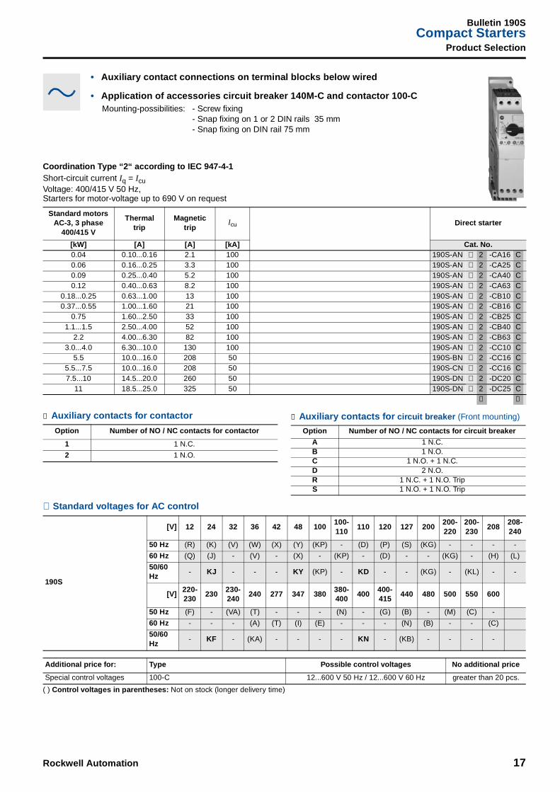
Product Selection
⊗ Standard voltages for AC control
( ) Control voltages in parentheses: Not on stock (longer delivery time)
Standard motors AC-3, 3 phase
400/415 V
Thermaltrip
Magnetictrip
Icu Direct starter
[kW] [A] [A] [kA] Cat. No.0.04 0.10...0.16 2.1 100 190S-AN ⊗ 2 -CA16 C0.06 0.16...0.25 3.3 100 190S-AN ⊗ 2 -CA25 C0.09 0.25...0.40 5.2 100 190S-AN ⊗ 2 -CA40 C0.12 0.40...0.63 8.2 100 190S-AN ⊗ 2 -CA63 C
0.18...0.25 0.63...1.00 13 100 190S-AN ⊗ 2 -CB10 C0.37...0.55 1.00...1.60 21 100 190S-AN ⊗ 2 -CB16 C
0.75 1.60...2.50 33 100 190S-AN ⊗ 2 -CB25 C1.1...1.5 2.50...4.00 52 100 190S-AN ⊗ 2 -CB40 C
2.2 4.00...6.30 82 100 190S-AN ⊗ 2 -CB63 C3.0...4.0 6.30...10.0 130 100 190S-AN ⊗ 2 -CC10 C
5.5 10.0...16.0 208 50 190S-BN ⊗ 2 -CC16 C5.5...7.5 10.0...16.0 208 50 190S-CN ⊗ 2 -CC16 C7.5...10 14.5...20.0 260 50 190S-DN ⊗ 2 -DC20 C
11 18.5...25.0 325 50 190S-DN ⊗ 2 -DC25 C➊ ➋
190S
[V] 12 24 32 36 42 48 100100-110
110 120 127 200200-220
200-230
208208-240
50 Hz (R) (K) (V) (W) (X) (Y) (KP) - (D) (P) (S) (KG) - - - -
60 Hz (Q) (J) - (V) - (X) - (KP) - (D) - - (KG) - (H) (L)
50/60 Hz
- KJ - - - KY (KP) - KD - - (KG) - (KL) - -
[V]220-230
230230-240
240 277 347 380380-400
400400-415
440 480 500 550 600
50 Hz (F) - (VA) (T) - - - (N) - (G) (B) - (M) (C) -
60 Hz - - - (A) (T) (I) (E) - - - (N) (B) - - (C)
50/60 Hz
- KF - (KA) - - - - KN - (KB) - - - -
Additional price for: Type Possible control voltages No additional price
Special control voltages 100-C 12...600 V 50 Hz / 12...600 V 60 Hz greater than 20 pcs.
Coordination Type “2“ according to IEC 947-4-1Short-circuit current Iq = IcuVoltage: 400/415 V 50 Hz, Starters for motor-voltage up to 690 V on request
• Auxiliary contact connections on terminal blocks below wired
• Application of accessories circuit breaker 140M-C and contactor 100-CMounting-possibilities: - Screw fixing
- Snap fixing on 1 or 2 DIN rails 35 mm- Snap fixing on DIN rail 75 mm
➊ Auxiliary contacts for contactor
Option Number of NO / NC contacts for contactor
1 1 N.C.
2 1 N.O.
➋ Auxiliary contacts for circuit breaker (Front mounting)
Option Number of NO / NC contacts for circuit breaker
A 1 N.C.B 1 N.O.C 1 N.O. + 1 N.C.D 2 N.O.R 1 N.C. + 1 N.O. TripS 1 N.O. + 1 N.O. Trip
Bulletin 140MCircuit Breakers
18 Rockwell Automation
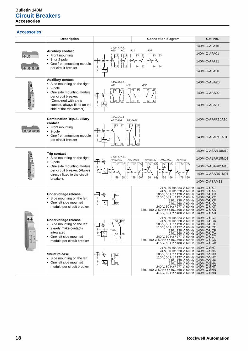
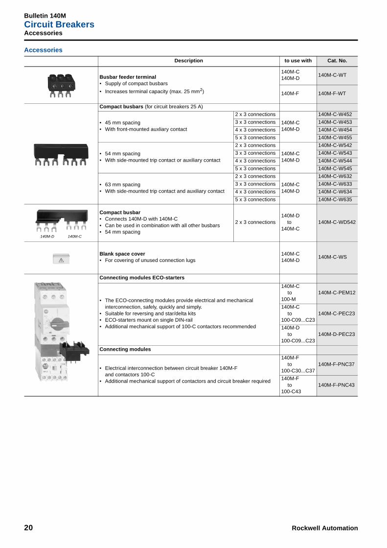
Accessories
Accessories
Description Connection diagram Cat. No.
Auxiliary contact• Front mounting• 1- or 2-pole• One front mounting module
per circuit breaker
140M-C-AFA10
140M-C-AFA01
140M-C-AFA11
140M-C-AFA20
Auxiliary contact• Side mounting on the right• 2-pole• One side mounting module
per circuit breaker. (Combined with a trip contact, always fitted on the side of the trip contact).
140M-C-ASA20
140M-C-ASA02
140M-C-ASA11
Combination Trip/Auxiliary contact• Front mounting• 2-pole• One front mounting module
per circuit breaker
140M-C-AFAR10A10
140M-C-AFAR10A01
Trip contact• Side mounting on the right• 2-pole• One side mounting module
per circuit breaker. (Always directly fitted to the circuit breaker).
140M-C-ASAR10M10
140M-C-ASAR10M01
140M-C-ASAR01M10
140M-C-ASAR01M01
140M-C-ASAM11
Undervoltage release• Side mounting on the left• One left side mounted
module per circuit breaker
21 V, 50 Hz / 24 V, 60 Hz24 V, 50 Hz / 28 V, 60 Hz
105 V, 50 Hz / 120 V, 60 Hz110 V, 50 Hz / 127 V, 60 Hz
220...230 V, 50 Hz240...260 V, 60 Hz
240 V, 50 Hz / 277 V, 60 Hz380...400 V, 50 Hz / 440...460 V, 60 Hz
415 V, 50 Hz / 480 V, 60 Hz
140M-C-UXJ140M-C-UXK140M-C-UXD140M-C-UXC140M-C-UXF140M-C-UXA140M-C-UXT140M-C-UXN140M-C-UXB
Undervoltage release• Side mounting on the left• 2 early make contacts
integrated • One left side mounted
module per circuit breaker
21 V, 50 Hz / 24 V, 60 Hz24 V, 50 Hz / 28 V, 60 Hz
105 V, 50 Hz / 120 V, 60 Hz110 V, 50 Hz / 127 V, 60 Hz
220...230 V, 50 Hz240...260 V, 60 Hz
240 V, 50 Hz / 277 V, 60 Hz380...400 V, 50 Hz / 440...460 V, 60 Hz
415 V, 50 Hz / 480 V, 60 Hz
140M-C-UCJ140M-C-UCK140M-C-UCD140M-C-UCC140M-C-UCF140M-C-UCA140M-C-UCT140M-C-UCN140M-C-UCB
Shunt release• Side mounting on the left• One left side mounted
module per circuit breaker
21 V, 50 Hz / 24 V, 60 Hz24 V, 50 Hz / 28 V, 60 Hz
105 V, 50 Hz / 120 V, 60 Hz110 V, 50 Hz / 127 V, 60 Hz
220...230 V, 50 Hz240...260 V, 60 Hz
240 V, 50 Hz / 277 V, 60 Hz380...400 V, 50 Hz / 440...460 V, 60 Hz
415 V, 50 Hz / 480 V, 60 Hz
140M-C-SNJ140M-C-SNK140M-C-SND140M-C-SNC140M-C-SNF140M-C-SNA140M-C-SNT140M-C-SNN140M-C-SNB
13
14
11
12
I >
13
14
21
22
13
14
23
24
140M-C-AF...A10 A01 A11 A20
33
34
41
42
I >
33
34
43
44
41
42
31
32
140M-C-AS...A11 A20 A02
13 27
14
11
12I >
28
27
28
140M-C-AF...AR10A10 AR10A01
57
58
67
68
I >
57
58
65
66
55
56
67
68
55
56
65
66
77
78
65
66
140M-C-AS...AR10M10 AR10M01 AR01M10 AR01M01 ASAM11
D1
D2I >
U <
D1
07I >
U <
D2
08
C1
C2I >

Rockwell Automation 19
Bulletin 140MCircuit Breakers
Accessories
Accessories
Description to use with Cat. No.
Anti-Tamper shield• Provides protection against inadvertent adjustment
of the current setting
140M-C140M-D140M-F
140M-C-CA
Lockable rotary handle• 1 padlock ø 3...6 mm• locking in “0“ position
black140M-C140M-D140M-F
140M-C-KN
red / yellow
140M-C140M-D
140M-C-KRY
140M-F 140M-F-KRY
Locking arrangement• Increases the padlockable facility of the lockable rotary handle• 1...3 padlocks ø 4...8 mm
140M-C-KN140M-C-KRY140M-F-KRY
140M-C-M3
Door coupling handle• Lockable with 1...3 padlocks ø 4...8 mm• Protection IP 66• Interlock override facility• Can be modified for locking in “1“ position• Scope of delivery: Door handle and couplingMounting-depth (Adapter - Door) 140-C 105.5 mm ± 5 mm
140-D 114.5 mm ± 5 mm140-F 137.1 mm ± 5 mm
(Please order extension shaft and legend plate separately)
black140M-C140M-D140M-F
140M-C-DN66
red / yellow140M-C140M-D140M-F
140M-C-DRY66
Extension shaft• Cut to required length forMounting-depth (Adapter - Door) 140-C 117...338 mm
140-D 126...347 mm140-F 149...369 mm
140M-C-DN66140M-C-DRY66
140M-C-DS
Legend plate• Marking: “Hauptschalter“ and “Main Switch“ black / grey 140M-C-DN66 140M-C-DFCN
• Marking: “Not-Aus“ and “Emergency - Off“ black / yellow 140M-C-DRY66 140M-C-DFCRY
Screw adapter clip• For screw mounting of a circuit breaker
140M-C140M-D140M-F
140M-C-N45
Bulletin 140MCircuit Breakers
20 Rockwell Automation
Accessories
Accessories
Description to use with Cat. No.
Busbar feeder terminal• Supply of compact busbars
• Increases terminal capacity (max. 25 mm2)
140M-C140M-D
140M-C-WT
140M-F 140M-F-WT
Compact busbars (for circuit breakers 25 A)
• 45 mm spacing• With front-mounted auxliary contact
2 x 3 connections
140M-C140M-D
140M-C-W452
3 x 3 connections 140M-C-W453
4 x 3 connections 140M-C-W454
5 x 3 connections 140M-C-W455
• 54 mm spacing• With side-mounted trip contact or auxiliary contact
2 x 3 connections
140M-C140M-D
140M-C-W542
3 x 3 connections 140M-C-W543
4 x 3 connections 140M-C-W544
5 x 3 connections 140M-C-W545
• 63 mm spacing• With side-mounted trip contact and auxiliary contact
2 x 3 connections
140M-C140M-D
140M-C-W632
3 x 3 connections 140M-C-W633
4 x 3 connections 140M-C-W634
5 x 3 connections 140M-C-W635
Compact busbar• Connects 140M-D with 140M-C• Can be used in combination with all other busbars• 54 mm spacing
2 x 3 connections140M-D
to140M-C
140M-C-WD542
Blank space cover• For covering of unused connection lugs
140M-C140M-D
140M-C-WS
Connecting modules ECO-starters
• The ECO-connecting modules provide electrical and mechanical interconnection, safely, quickly and simply.
• Suitable for reversing and star/delta kits• ECO-starters mount on single DIN-rail• Additional mechanical support of 100-C contactors recommended
140M-Cto
100-M140M-C-PEM12
140M-Cto
100-C09...C23140M-C-PEC23
140M-Dto
100-C09...C23140M-D-PEC23
Connecting modules
• Electrical interconnection between circuit breaker 140M-F and contactors 100-C
• Additional mechanical support of contactors and circuit breaker required
140M-Fto
100-C30...C37140M-F-PNC37
140M-Fto
100-C43140M-F-PNC43
140M-D 140M-C
Rockwell Automation 21
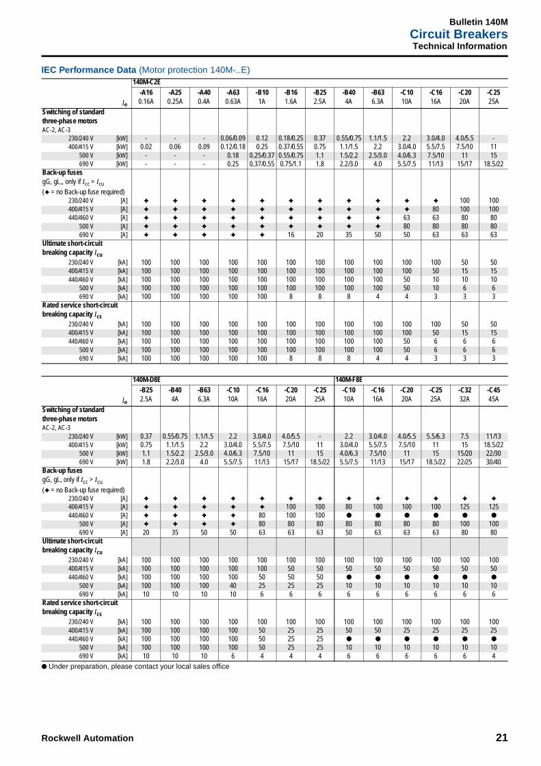
Bulletin 140MCircuit BreakersTechnical Information
IEC Performance Data (Motor protection 140M-..E)
● Under preparation, please contact your local sales office
Ie
140M-C2E-A160.16A
-A250.25A
-A400.4A
-A630.63A
-B101A
-B161.6A
-B252.5A
-B404A
-B636.3A
-C1010A
-C1616A
-C2020A
-C2525A
Switching of standardthree-phase motorsAC-2, AC-3
230/240 V [kW] - - - 0.06/0.09 0.12 0.18/0.25 0.37 0.55/0.75 1.1/1.5 2.2 3.0/4.0 4.0/5.5 -400/415 V [kW] 0.02 0.06 0.09 0.12/0.18 0.25 0.37/0.55 0.75 1.1/1.5 2.2 3.0/4.0 5.5/7.5 7.5/10 11
500 V [kW] - - - 0.18 0.25/0.37 0.55/0.75 1.1 1.5/2.2 2.5/3.0 4.0/6.3 7.5/10 11 15690 V [kW] - - - 0.25 0.37/0.55 0.75/1.1 1.8 2.2/3.0 4.0 5.5/7.5 11/13 15/17 18.5/22
Back-up fusesgG, gL,, only if Icc > Icu
(✦ = no Back-up fuse required)230/240 V [A] ✦ ✦ ✦ ✦ ✦ ✦ ✦ ✦ ✦ ✦ ✦ 100 100400/415 V [A] ✦ ✦ ✦ ✦ ✦ ✦ ✦ ✦ ✦ ✦ 80 100 100440/460 V [A] ✦ ✦ ✦ ✦ ✦ ✦ ✦ ✦ ✦ 63 63 80 80
500 V [A] ✦ ✦ ✦ ✦ ✦ ✦ ✦ ✦ ✦ 80 80 80 80690 V [A] ✦ ✦ ✦ ✦ ✦ 16 20 35 50 50 63 63 63
Ultimate short-circuitbreaking capacity Icu
230/240 V [kA] 100 100 100 100 100 100 100 100 100 100 100 50 50400/415 V [kA] 100 100 100 100 100 100 100 100 100 100 50 15 15440/460 V [kA] 100 100 100 100 100 100 100 100 100 50 10 10 10
500 V [kA] 100 100 100 100 100 100 100 100 100 50 10 6 6690 V [kA] 100 100 100 100 100 8 8 8 4 4 3 3 3
Rated service short-circuitbreaking capacity Ics
230/240 V [kA] 100 100 100 100 100 100 100 100 100 100 100 50 50400/415 V [kA] 100 100 100 100 100 100 100 100 100 100 50 15 15440/460 V [kA] 100 100 100 100 100 100 100 100 100 50 6 6 6
500 V [kA] 100 100 100 100 100 100 100 100 100 50 6 6 6690 V [kA] 100 100 100 100 100 8 8 8 4 4 3 3 3
Ie
140M-D8E 140M-F8E-B252.5A
-B404A
-B636.3A
-C1010A
-C1616A
-C2020A
-C2525A
-C1010A
-C1616A
-C2020A
-C2525A
-C3232A
-C4545A
Switching of standardthree-phase motorsAC-2, AC-3
230/240 V [kW] 0.37 0.55/0.75 1.1/1.5 2.2 3.0/4.0 4.0/5.5 - 2.2 3.0/4.0 4.0/5.5 5.5/6.3 7.5 11/13400/415 V [kW] 0.75 1.1/1.5 2.2 3.0/4.0 5.5/7.5 7.5/10 11 3.0/4.0 5.5/7.5 7.5/10 11 15 18.5/22
500 V [kW] 1.1 1.5/2.2 2.5/3.0 4.0/6.3 7.5/10 11 15 4.0/6.3 7.5/10 11 15 15/20 22/30690 V [kW] 1.8 2.2/3.0 4.0 5.5/7.5 11/13 15/17 18.5/22 5.5/7.5 11/13 15/17 18.5/22 22/25 30/40
Back-up fusesgG, gL, only if Icc > Icu
(✦ = no Back-up fuse required)230/240 V [A] ✦ ✦ ✦ ✦ ✦ ✦ ✦ ✦ ✦ ✦ ✦ ✦ ✦
400/415 V [A] ✦ ✦ ✦ ✦ ✦ 100 100 80 100 100 100 125 125440/460 V [A] ✦ ✦ ✦ ✦ 80 100 100 ● ● ● ● ● ●
500 V [A] ✦ ✦ ✦ ✦ 80 80 80 80 80 80 80 100 100690 V [A] 20 35 50 50 63 63 63 50 63 63 63 80 80
Ultimate short-circuitbreaking capacity Icu
230/240 V [kA] 100 100 100 100 100 100 100 100 100 100 100 100 100400/415 V [kA] 100 100 100 100 100 50 50 50 50 50 50 50 50440/460 V [kA] 100 100 100 100 50 50 50 ● ● ● ● ● ●
500 V [kA] 100 100 100 40 25 25 25 10 10 10 10 10 10690 V [kA] 10 10 10 10 6 6 6 6 6 6 6 6 6
Rated service short-circuitbreaking capacity Ics
230/240 V [kA] 100 100 100 100 100 100 100 100 100 100 100 100 100400/415 V [kA] 100 100 100 100 50 25 25 50 50 25 25 25 25440/460 V [kA] 100 100 100 100 50 25 25 ● ● ● ● ● ●
500 V [kA] 100 100 100 100 50 25 25 10 10 10 10 10 10690 V [kA] 10 10 10 6 4 4 4 6 6 6 6 6 4
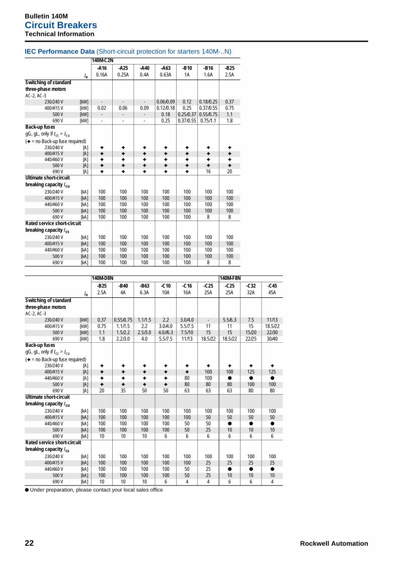
Bulletin 140MCircuit Breakers
22 Rockwell Automation
Technical Information
IEC Performance Data (Short-circuit protection for starters 140M-..N)
● Under preparation, please contact your local sales office
Ie
140M-C2N-A160.16A
-A250.25A
-A400.4A
-A630.63A
-B101A
-B161.6A
-B252.5A
Switching of standardthree-phase motorsAC-2, AC-3
230/240 V [kW] - - - 0.06/0.09 0.12 0.18/0.25 0.37400/415 V [kW] 0.02 0.06 0.09 0.12/0.18 0.25 0.37/0.55 0.75
500 V [kW] - - - 0.18 0.25/0.37 0.55/0.75 1.1690 V [kW] - - - 0.25 0.37/0.55 0.75/1.1 1.8
Back-up fusesgG, gL, only if Icc > Icu
(✦ = no Back-up fuse required)230/240 V [A] ✦ ✦ ✦ ✦ ✦ ✦ ✦
400/415 V [A] ✦ ✦ ✦ ✦ ✦ ✦ ✦
440/460 V [A] ✦ ✦ ✦ ✦ ✦ ✦ ✦
500 V [A] ✦ ✦ ✦ ✦ ✦ ✦ ✦
690 V [A] ✦ ✦ ✦ ✦ ✦ 16 20Ultimate short-circuitbreaking capacity Icu
230/240 V [kA] 100 100 100 100 100 100 100400/415 V [kA] 100 100 100 100 100 100 100440/460 V [kA] 100 100 100 100 100 100 100
500 V [kA] 100 100 100 100 100 100 100690 V [kA] 100 100 100 100 100 8 8
Rated service short-circuitbreaking capacity Ics
230/240 V [kA] 100 100 100 100 100 100 100400/415 V [kA] 100 100 100 100 100 100 100440/460 V [kA] 100 100 100 100 100 100 100
500 V [kA] 100 100 100 100 100 100 100690 V [kA] 100 100 100 100 100 8 8
Ie
140M-D8N 140M-F8N-B252.5A
-B404A
-B636.3A
-C1010A
-C1616A
-C2525A
-C2525A
-C3232A
-C4545A
Switching of standardthree-phase motorsAC-2, AC-3
230/240 V [kW] 0.37 0.55/0.75 1.1/1.5 2.2 3.0/4.0 - 5.5/6.3 7.5 11/13400/415 V [kW] 0.75 1.1/1.5 2.2 3.0/4.0 5.5/7.5 11 11 15 18.5/22
500 V [kW] 1.1 1.5/2.2 2.5/3.0 4.0//6.3 7.5/10 15 15 15/20 22/30690 V [kW] 1.8 2.2/3.0 4.0 5.5/7.5 11/13 18.5/22 18.5/22 22/25 30/40
Back-up fusesgG, gL, only if Icc > Icu
(✦ = no Back-up fuse required)230/240 V [A] ✦ ✦ ✦ ✦ ✦ ✦ ✦ ✦ ✦
400/415 V [A] ✦ ✦ ✦ ✦ ✦ 100 100 125 125440/460 V [A] ✦ ✦ ✦ ✦ 80 100 ● ● ●
500 V [A] ✦ ✦ ✦ ✦ 80 80 80 100 100690 V [A] 20 35 50 50 63 63 63 80 80
Ultimate short-circuitbreaking capacity Icu
230/240 V [kA] 100 100 100 100 100 100 100 100 100400/415 V [kA] 100 100 100 100 100 50 50 50 50440/460 V [kA] 100 100 100 100 50 50 ● ● ●
500 V [kA] 100 100 100 100 50 25 10 10 10690 V [kA] 10 10 10 6 6 6 6 6 6
Rated service short-circuitbreaking capacity Ics
230/240 V [kA] 100 100 100 100 100 100 100 100 100400/415 V [kA] 100 100 100 100 100 25 25 25 25440/460 V [kA] 100 100 100 100 50 25 ● ● ●
500 V [kA] 100 100 100 100 50 25 10 10 10690 V [kA] 10 10 10 6 4 4 6 6 4

Rockwell Automation 23
Bulletin 140MCircuit BreakersTechnical Information
IEC Performance Data (Transformer protection 140M-..T)
● Under preparation, please contact your local sales office
Ie
140M-C2T-A160.16A
-A250.25A
-A400.4A
-A630.63A
-B101A
-B161.6A
-B252.5A
-B404A
-B636.3A
-C1010A
-C1616A
Switching of standardthree-phase motorsAC-2, AC-3
230/240 V [kW] - - - 0.06/0.09 0.12 0.18/0.25 0.37 0.55/0.75 1.1/1.5 2.2 3.0/4.0400/415 V [kW] 0.02 0.06 0.09 0.12/0.18 0.25 0.37/0.55 0.75 1.1/1.5 2.2 3.0/4.0 5.5/7.5
500 V [kW] - - - 0.18 0.25/0.37 0.55/0.75 1.1 1.5/2.2 2.5/3.0 4.0/6.3 7.5/10690 V [kW] - - - 0.25 0.37/0.55 0.75/1.1 1.8 2.2/3.0 4.0 5.5/7.5 11/13
Back-up fusesgG, gL, only if Icc > Icu
(✦ = no Back-up fuse required)230/240 V [A] ✦ ✦ ✦ ✦ ✦ ✦ ✦ ✦ ✦ ✦ ✦
400/415 V [A] ✦ ✦ ✦ ✦ ✦ ✦ ✦ ✦ ✦ ✦ 80440/460 V [A] ✦ ✦ ✦ ✦ ✦ ✦ ✦ ✦ ✦ 63 63
500 V [A] ✦ ✦ ✦ ✦ ✦ ✦ ✦ ✦ ✦ 80 80690 V [A] ✦ ✦ ✦ ✦ ✦ 16 20 35 50 50 63
Ultimate short-circuitbreaking capacity Icu
230/240 V [kA] 100 100 100 100 100 100 100 100 100 100 100400/415 V [kA] 100 100 100 100 100 100 100 100 100 100 15440/460 V [kA] 100 100 100 100 100 100 100 100 100 50 10
500 V [kA] 100 100 100 100 100 100 100 100 100 50 6690 V [kA] 100 100 100 100 100 8 8 8 4 4 3
Rated service short-circuitbreaking capacity Ics
230/240 V [kA] 100 100 100 100 100 100 100 100 100 100 100400/415 V [kA] 100 100 100 100 100 100 100 100 100 100 15440/460 V [kA] 100 100 100 100 100 100 100 100 100 50 6
500 V [kA] 100 100 100 100 100 100 100 100 100 50 6690 V [kA] 100 100 100 100 100 8 8 8 4 4 3
Ie
140M-D8T 140M-F8T-C1616A
-C2020A
-C2525A
-C3232A
Switching of standardthree-phase motorsAC-2, AC-3
230/240 V [kW] 3.0/4.0 4.0/5.5 5.5/6.3 7.5400/415 V [kW] 5.5/7.5 7.5/10 11 15
500 V [kW] 7.5/10 11 15 15/20690 V [kW] 11/13 15/17 18.5/22 22/25
Back-up fusesgG, gL, only if Icc > Icu
(✦ = no Back-up fuse required)230/240 V [A] ✦ ✦ ✦ ✦
400/415 V [A] 80 100 100 125440/460 V [A] 80 100 ● ●
500 V [A] 80 80 80 100690 V [A] 63 63 63 80
Ultimate short-circuitbreaking capacity Icu
230/240 V [kA] 100 100 100 100400/415 V [kA] 50 50 50 50440/460 V [kA] 50 50 ● ●
500 V [kA] 25 25 10 10690 V [kA] 6 6 6 6
Rated service short-circuitbreaking capacity Ics
230/240 V [kA] 100 100 100 100400/415 V [kA] 25 25 25 25440/460 V [kA] 25 25 ● ●
500 V [kA] 25 25 10 10690 V [kA] 4 4 6 6

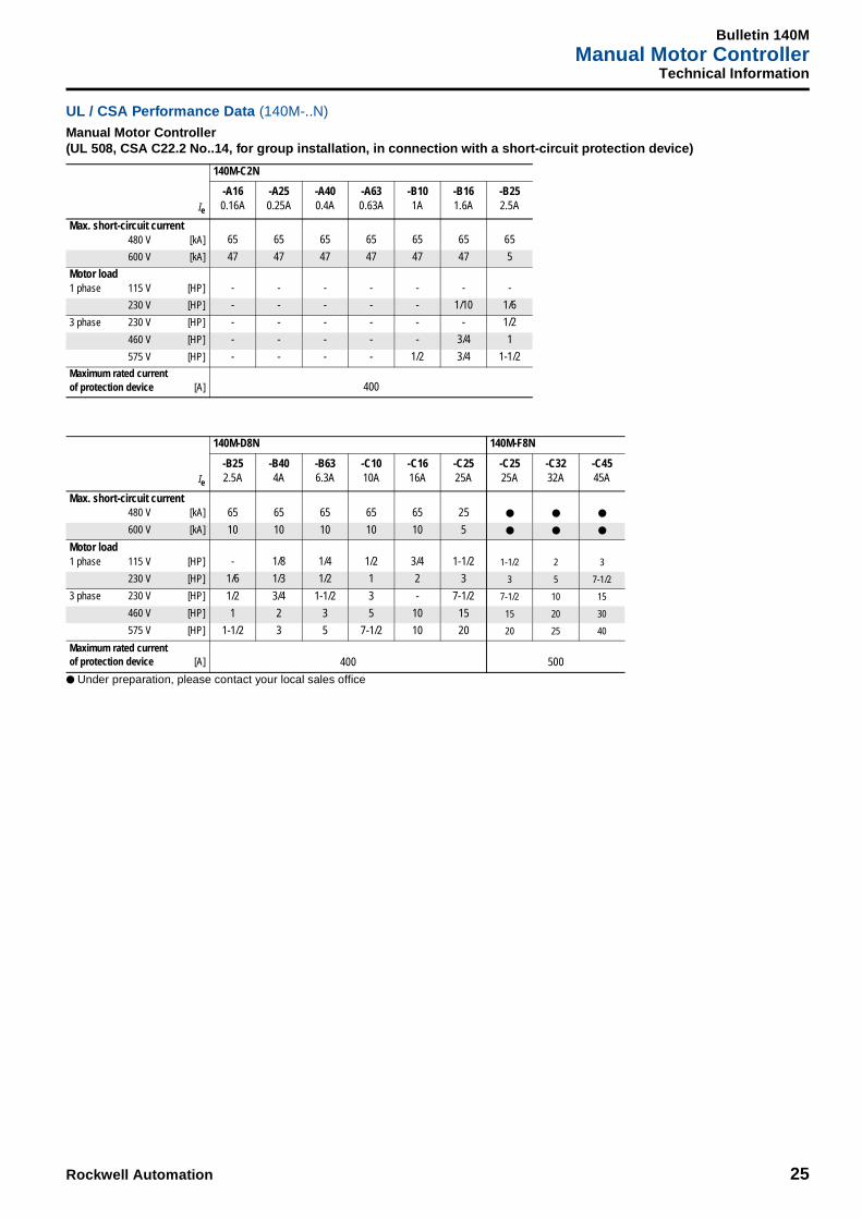
Bulletin 140MManual Motor Controller
24 Rockwell Automation
Technical Information
UL / CSA Performance Data (Motor protection 140M-..E)
Manual Motor Controller(UL 508, CSA C22.2 No..14, for group installation, in connection with a short-circuit protection device)
● Under preparation, please contact your local sales office
Ie
140M-C2E
-A160.16A
-A250.25A
-A400.4A
-A630.63A
-B101A
-B161.6A
-B252.5A
-B404A
-B636.3A
-C1010A
-C1616A
-C2020A
-C2525A
Max. short-circuit current480 V [kA] 65 65 65 65 65 65 65 65 65 65 10 10 10
600 V [kA] 47 47 47 47 47 47 5 5 5 5 5 5 5
Motor load1 phase 115 V [HP] - - - - - - - 1/8 1/4 1/2 3/4 1 1-1/2
230 V [HP] - - - - - 1/10 1/6 1/3 1/2 1 2 3 -
3 phase 230 V [HP] - - - - - - 1/2 3/4 1-1/2 3 5 5 7-1/2
460 V [HP] - - - - - 3/4 1 2 3 5 10 - 15
575 V [HP] - - - - 1/2 3/4 1-1/2 3 5 7-1/2 10 15 20
Maximum rated currentof protection device [A] 400
Ie
140M-D8E 140M-F8E
-B252.5A
-B404A
-B636.3A
-C1010A
-C1616A
-C2020A
-C2525A
-C1010A
-C1616A
-C2020A
-C2525A
-C3232A
-C4545A
Max. short-circuit current480 V [kA] 65 65 65 65 65 65 25 ● ● ● ● ● ●
600 V [kA] 10 10 10 10 10 5 5 ● ● ● ● ● ●
Motor load1 phase 115 V [HP] - 1/8 1/4 1/2 3/4 1 1-1/2 1/2 3/4 1 1-1/2 2 3
230 V [HP] 1/6 1/3 1/2 1 2 3 - 1 2 3 - 5 7-1/2
3 phase 230 V [HP] 1/2 3/4 1-1/2 3 - 5 7-1/2 3 - 5 7-1/2 10 15
460 V [HP] 1 2 3 5 10 - 15 5 10 - 15 20 30
575 V [HP] 1-1/2 3 5 7-1/2 10 15 20 7-1/2 10 15 20 25 40
Maximum rated currentof protection device [A] 400 500
Rockwell Automation 25
Bulletin 140MManual Motor Controller
Technical Information
UL / CSA Performance Data (140M-..N)
Manual Motor Controller(UL 508, CSA C22.2 No..14, for group installation, in connection with a short-circuit protection device)
● Under preparation, please contact your local sales office
Ie
140M-C2N
-A160.16A
-A250.25A
-A400.4A
-A630.63A
-B101A
-B161.6A
-B252.5A
Max. short-circuit current480 V [kA] 65 65 65 65 65 65 65
600 V [kA] 47 47 47 47 47 47 5
Motor load1 phase 115 V [HP] - - - - - - -
230 V [HP] - - - - - 1/10 1/6
3 phase 230 V [HP] - - - - - - 1/2
460 V [HP] - - - - - 3/4 1
575 V [HP] - - - - 1/2 3/4 1-1/2
Maximum rated currentof protection device [A] 400
Ie
140M-D8N 140M-F8N
-B252.5A
-B404A
-B636.3A
-C1010A
-C1616A
-C2525A
-C2525A
-C3232A
-C4545A
Max. short-circuit current480 V [kA] 65 65 65 65 65 25 ● ● ●
600 V [kA] 10 10 10 10 10 5 ● ● ●
Motor load1 phase 115 V [HP] - 1/8 1/4 1/2 3/4 1-1/2 1-1/2 2 3
230 V [HP] 1/6 1/3 1/2 1 2 3 3 5 7-1/2
3 phase 230 V [HP] 1/2 3/4 1-1/2 3 - 7-1/2 7-1/2 10 15
460 V [HP] 1 2 3 5 10 15 15 20 30
575 V [HP] 1-1/2 3 5 7-1/2 10 20 20 25 40
Maximum rated currentof protection device [A] 400 500

Bulletin 140MManual Motor Controller
26 Rockwell Automation
Technical Information
UL / CSA Performance Data (Transformer protection 140M-..T)
Manual Motor Controller(UL 508, CSA C22.2 No..14, for group installation, in connection with a short-circuit protection device)
● Under preparation, please contact your local sales office
Combination Motor Controller construction Typ E
(Approval under preparation)
Ie
140M-C2T
-A160.16A
-A250.25A
-A400.4A
-A630.63A
-B101A
-B161.6A
-B252.5A
-B404A
-B636.3A
-C1010A
-C1616A
Max. short-circuit current480 V [kA] 65 65 65 65 65 65 65 65 65 65 10
600 V [kA] 47 47 47 47 47 47 10 10 5 5 5
Motor load1 phase 115 V [HP] - - - - - - - 1/8 1/4 1/2 3/4
230 V [HP] - - - - - 1/10 1/6 1/3 1/2 1 2
3 phase 230 V [HP] - - - - - - 1/2 3/4 1-1/2 3 5
460 V [HP] - - - - - 3/4 1 2 3 5 10
575 V [HP] - - - - 1/2 3/4 1-1/2 3 5 7-1/2 10
Maximum rated currentof protection device [A] 400
Ie
140M-D8T 140M-F8T
-C1616A
-C2020A
-C2525A
-C3232A
Max. short-circuit current480 V [kA] 65 65 ● ●
600 V [kA] 10 5 ● ●
Motor load1 phase 115 V [HP] 3/4 1 1-1/2 2
230 V [HP] 2 3 - 5
3 phase 230 V [HP] - 5 7-1/2 10
460 V [HP] 10 - 15 20
575 V [HP] 10 15 20 25
Maximum rated currentof protection device [A] 400 500
Rockwell Automation 27
Bulletin 140MCircuit BreakersTechnical Information
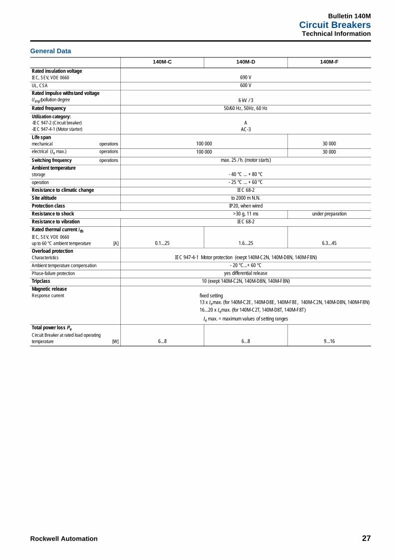
General Data
140M-C 140M-D 140M-F
Rated insulation voltageIEC, SEV, VDE 0660 690 V
UL, CSA 600 V
Rated impulse withstand voltageUimp/pollution degree 6 kV / 3
Rated frequency 50/60 Hz, 50Hz, 60 Hz
Utilization category: -IEC 947-2 (Circuit breaker) -IEC 947-4-1 (Motor starter)
AAC-3
Life spanmechanical operations 100 000 30 000
electrical (Ie max.) operations 100 000 30 000
Switching frequency operations max. 25 / h. (motor starts)
Ambient temperaturestorage - 40 °C ... + 80 °C
operation - 25 °C ... + 60 °C
Resistance to climatic change IEC 68-2
Site altitude to 2000 m N.N.
Protection class IP20, when wired
Resistance to shock >30 g, 11 ms under preparation
Resistance to vibration IEC 68-2
Rated thermal current IthIEC, SEV, VDE 0660up to 60 °C ambient temperature [A] 0.1...25 1.6...25 6.3...45
Overload protectionCharacteristics IEC 947-4-1 Motor protection (exept 140M-C2N, 140M-D8N, 140M-F8N)
Ambient temperature compensation - 20 °C...+ 60 °C
Phase-failure protection yes differential release
Tripclass 10 (exept 140M-C2N, 140M-D8N, 140M-F8N)
Magnetic releaseResponse current fixed setting
13 x Iemax. (for 140M-C2E, 140M-D8E, 140M-F8E, 140M-C2N, 140M-D8N, 140M-F8N)
16...20 x Iemax. (for 140M-C2T, 140M-D8T, 140M-F8T)
Ie max. = maximum values of setting ranges
Total power loss PvCircuit Breaker at rated load operatingtemperature [W] 6...8 6...8 9...16

Bulletin 140MCircuit Breakers
28 Rockwell Automation
Technical Information
General Data
Accessories for Circuit Breaker 140M
140M-C 140M-D 140M-F
Conformity to standards IEC 947;EN 60947;
UL 508; CSA 22.2 Teil 14Approvals CE, UL, CSA
Terminal partsType of terminals
Screwdriver Pozidriv No. 2 / Blade No. 3 Pozidriv No. 2 / Blade No. 4
1.conductor [mm2] / [AWG]
2.conductor [mm2] / [AWG]
1...4 / No. 16...121...4 / No. 16...12
2.5...16 / No.14...62.5...10 / No. 14...8
1.conductor [mm2] / [AWG]
2.conductor [mm2] / [AWG]
1...6 / No. 16...81...6 / No. 16...8
2.5...25 / No. 14...42.5...16 / No. 14...6
1.conductor [mm2] / [AWG]
2.conductor [mm2] / [AWG]
1.5...6 / No. 16...81.5...6 / No. 16...8
2.5...25 / No. 14...42.5...16 / No. 14...6
Tightening torque [Nm] / [lb-in] 1...2.5 / 8.9...22 1.5...3.5 / 13...31
Auxiliary contacts for front mounting140M-C-AFA.., 140M-C-AFAR...
Auxiliary contacts for right side mounting140M-C-ASA.., 140M-C-ASAR...
Rated thermal current Ith
at 40 °C ambient temperature [A]at 60 °C ambient temperature [A]
54
106
Contact class coordination according to NEMA(UL/CSA-Standards) AC
DCB 300Q 300
B 600Q 600
Back-up fuses gG, gL [A] 10 10Rated supply current [V]AC-15: [A]
244
1203
2401.5
246
1205
2403
4152
6900.7
DC-13: [V][A]
242
1200.5
2400.25
242
1200.5
2400.25
4150.15
Terminal partsType of terminals
Screwdriver Pozidriv No. 2 / Blade No. 3
1.conductor [mm2] / [AWG]
2.conductor [mm2] / [AWG]
0.5...2.5 / No. 18...140.5...2.5 / No. 18...14
1.conductor [mm2] / [AWG]
2.conductor [mm2] / [AWG]
0.75...2.5 / No. 18...140.75...2.5 / No. 18...14
1.conductor [mm2] / [AWG]
2.conductor [mm2] / [AWG]
0.75...2.5 / No. 18...140.75...2.5 / No. 18...14
Tightening torque [Nm] / [lb-in] 1.5 / 13.3

Rockwell Automation 29
Bulletin 140MCircuit BreakersTechnical Information
Accessories for Circuit Breaker 140M
Weights
Undervoltage releasefor left side mounting
140M-C-UX..
Undervoltage release with 2 auxiliary contacts for left side mounting
140M-C-UC..
Shunt releasefor left side mounting
140M-C-SN..
Actuating voltagePull-inDrop-out
0.85...1.1 x Us
0.7...0.35 x Us
0.85...1.1 x Us
0.7...0.35 x Us
0.7...1.1 x Us
0.7...0.35 x Us
Rated control voltagemin.:max.:
21 V 50 Hz/24 V 60 Hz600 V 50 Hz (UL max. 300 V)
21 V 50 Hz/24 V 60 Hz600 V 50 Hz
21 V 50 Hz/24 V 60 Hz600 V 50 Hz (UL max. 300 V)
Coil ratingPull-inHold
8.5 VA, 6 W3 VA, 1.2 W
8.5 VA, 6 W3 VA, 1.2 W
8.5 VA, 6 W3 VA, 1.2 W
On-Time 100 % 100 % 100 %
Terminal partsType of terminals
Screwdriver Pozidriv No. 2 / Blade No. 3
1.conductor [mm2] / [AWG]
2.conductor [mm2] / [AWG]
0.5...2.5 / No. 18...140.5...2.5 / No. 18...14
1.conductor [mm2] / [AWG]
2.conductor [mm2] / [AWG]
0.75...2.5 / No. 18...140.75...2.5 / No. 18...14
1.conductor [mm2] / [AWG]
2.conductor [mm2] / [AWG]
0.75...2.5 / No. 18...140.75...2.5 / No. 18...14
Tightening torque [Nm] / [lb-in] 1.5 / 13.3
Busbar feeder terminal140M-C-WT
Compact busbar140M-C-W...
Rated thermal current Ith
at 60 °C ambient temperature [A] 63 63
1.conductor [mm2] / [AWG]
2.conductor [mm2] / [AWG]
4...164...10
-
1.conductor [mm2] / [AWG]
2.conductor [mm2] / [AWG]
6...25 / No. 14...46...16 / No. 14...6
-
1.conductor [mm2] / [AWG]
2.conductor [mm2] / [AWG]
6...25 / No. 14...46...16 / No. 14...6
-
Tightening torque [Nm] / [lb-in] 3 / 27 -
Description Type Weights
Circuit Breaker
140M-C2E-...140M-D8E-...140M-F8E-...
317 g373 g782 g
140M-C2N-...140M-D8N-...140M-F8N-...
315 g365 g782 g
140M-C2T-...140M-D8T-...140M-F8T-...
315 g365 g782 g
Auxiliary contact
140M-C-AFA10140M-C-AFA01
10 g140M-C-AFA11140M-C-AFA20140M-C-ASA..140M-C-AFAR10A..
15 g140M-C-ASAR..M..140M-C-ASAM11
Undervoltage release140M-C-UX. 108 g140M-C-SN. 110 g140M-C-UC. 116 g
Anti tamper cover 140M-C-CA 2 g
Description Type Weights
Lockable rotary handle140M-C-KN140M-C-KRY
5 g
Locking arrangement 140M-C-M3 30 g
Door coupling handle140M-C-DN66140M-C-NRY66
123 g
Extension shaft 140M-C-DS 46 g
Legend plate 140M-C-DFC.. 4 g
Busbar feeder terminal140M-C-WT140M-F-WT
172 g
Compact busbars
140M-C-W452140M-C-W453140M-C-W454140M-C-W455
47 g80 g
104 g132 g
140M-C-W542140M-C-W543140M-C-W544140M-C-W545
52 g86 g
118 g154 g
140M-C-W632140M-C-W633140M-C-W634140M-C-W635
56 g92 g
134 g170 g

Bulletin 140MCircuit Breakers
30 Rockwell Automation
Technical Information
Type "2" Coordination according to IEC 947-4-1• Short-circuit current Iq = 50 kA
• Voltage: 400/415 V, 50 Hz
Definition Type "2" Coordination according to IEC 947-4-1:• The contactor or the starter must not endanger persons or systems in the event of a short-circuit.• The contactor or the starter must be suitable for further use.• No damage to the overload relay or other parts may occur with the exception of welding of the contactor or starter contacts provided that these
can be easily separated without significant deformation (such as with a screwdriver).
In the event of short-circuit, fast opening, current limiting circuit breakers 140M make it possible to build economical, fully short-circuit coordinated starter combinations in accordance with IEC 947-4-1, coordination type "2".
Coordination type “2“ without oversizing of contactors means: Type “1“ = Type “2“
Standard motorsAC-3
at 400/415 V1500 rpm Circuit Breaker
Thermal overload release
Setting rangeMagnetic releaseResponse current Contactor IAC-3
[kW] [A] Cat. No. [A] [A] Cat. No. [A]
0.06 0.23 140M-C2E-A25 0.16...0.25 3.3 100-C09 9
0.09 0.32 140M-C2E-A40 0.25...0.40 5.2 100-C09 9
0.12 0.41 140M-C2E-A63 0.40...0.63 8.2 100-C09 9
0.18 0.59 140M-C2E-A63 0.40...0.63 8.2 100-C09 9
0.25 0.77 140M-C2E-B10 0.63...1.0 13 100-C09 9
0.37 1.1 140M-C2E-B16 1.0...1.6 21 100-C09 9
0.55 1.5 140M-C2E-B16 1.0...1.6 21 100-C09 9
0.75 1.9 140M-C2E-B25 1.6...2.5 33 100-C09 9
1.1 2.6 140M-C2E-B40 2.5...4.0 52 100-C09 9
1.5 3.4 140M-C2E-B40 2.5...4.0 52 100-C09 9
2.2 4.8 140M-C2E-B63 4.0...6.3 82 100-C09 9
3.0 6.3 140M-C2E-C10 6.3...10.0 130 100-C09 9
4.0 8.2 140M-C2E-C10 6.3... 10.0 130 100-C09 9
5.5 10.9 140M-C2E-C16 10.0...16.0 208 100-C12 12
7.5 14.7 140M-C2E-C16 10.0...16.0 208 100-C16 16
11.0 21.0 140M-D8E-C25 18.0...25.0 325 100-C23 23
15.0 27.9 140M-F8E-C32 23.0...32.0 416 100-C30 30
18.5 34.4 140M-F8E-C45 32.0...45.0 585 100-C37 37
22.0 39.6 140M-F8E-C45 32.0...45.0 585 100-C43 43
30.0 53.6 140-CMN-6300 40.0...63.0 882 100-C60 60
37.0 65.3 140-CMN-9000 63.0...90.0 1260 100-C72 72
45.0 78.2 140-CMN-9000 63.0...90.0 1260 100-C85 85

Rockwell Automation 31
Bulletin 140MCircuit BreakersTechnical Information
Time / Current Characteristic
Circuit Breaker 140M
1) Thermal release trip current:The adjustable inverse bimetal trip reliability protects motors against overloads. The curve shows the mean operating current at an ambient temperature of 20 °C starting from cold. Careful testing and setting ensures effective motor protection even in the case of single-phasing.Overload characteristic also valid for transformer protection.
2) Magnetic release trip current:The instantaneous magnetic trip has a fixed operating current setting. This corresponds to 13 times the highest setting of the thermal overload trip. (Transformer protection ~20 x Ie max.)At the upper thermal release setting, this tripping current is 13 (20) times; at a lower setting it is correspondingly higher.
Current setting IeF: The overload trip corresponds to a thermal overload relay in a motor starter conforming to IEC 947-4-1. If a different value is prescribed (e.g. reduced Ie for cooling medium having a temperature higher than 40 °C or a place of installation higher than 2000 m above sea level), the setting current is equal to the reduced rated current Ie of the motor.
0.8
1 000
10 000
100
10
1
0.1
0.01
0.001
1 2 4 6 20 40 60 10010
1h
1
2
Multiple of set current IeF
Trip
ping
tim
e [s
]

Bulletin 140MCircuit Breakers
32 Rockwell Automation
Technical Information
Dimensions in mm (inches)
90˚ 90˚90˚ 90˚
9(23/64)
24.8 (31/32)
90 (
3-35
/64)
18(23/32)
4.5
(3/1
6)
45(1-25/32)
➌
➋ 54 (2-1/8)
72 (2-53/64) 7.5(19/64)
4.5(3/16)
➍
➊
45 (
1-25
/32)
45 (
1-25
/32)
44 (1-47/64)
62 (2-7/16)
4.5(3/16) 7.5
(19/64)
➍
➊
45 (
1-25
/32)
45 (
1-25
/32)
45 (
1-25
/32)
➋
➍
18(23/32)
4.5
(3/1
6)
➌
55 (
2-11
/64)
110
(4-2
1/64
)
29.4 (1-5/32)
54(2-1/8)
9(23/64)
91 (3-37/64)
➊
55 (
2-11
/64)
4.5(3/16) 102 (4-1/64) 7.5
(19/64)
45 (
1-25
/32) ➊ Mounting on DIN-rail EN 50 022-35
➋ Auxiliary contact (side mounted)➌ Undervoltage release or shunt release➍ Auxiliary contact (front mounted)
Mounting position 140M-C..., 140M-D..., 140M-F...
140M-C..., 140M-D... 140M-C.... 140M-D...
➋
➍
18(23/32)
4.5
(3/1
6)
➌
55 (
2-11
/64)
110
(4-2
1/64
)
29.4 (1-5/32)
54(2-1/8)
9(23/64)
91 (3-37/64)
➊
55 (
2-11
/64)
4.5(3/16) 102 (4-1/64) 7.5
(19/64)
45 (
1-25
/32)
140M-F....
min. 100
53.5
53.5
a
1.5...535...45
4.5
3.5
4...8
b
+ 5 mm
2.4
4.5
c2c1
140M-C-D...66
a b c1 c2140M-C2E 117...338 105.5 ±5 49.5 40.5
140M-D8E 126...347 114.5 ±5 49.5 40.5
140M-F8E 148.6...369.6 137.1 ±5 59.35 50.35
SlimlineSolutionsfor MotorManagement
The New MCS Circuit BreakersBulletin 140M
Copyright 1999 Rockwell Automation, Printed in SwitzerlandPublication 0140M-CA001A-EN-P July 1999