burgan cape terminals (pty) ltd, cape town harbour€¦ · burgan cape terminals (pty) ltd will...
TRANSCRIPT

The world’s leading sustainability consultancy
Burgan Cape Terminals (Pty) Ltd, Cape Town Harbour
Major Hazard Installation Risk Assessment v2.0 Ref: 0305334
July 2015
www.erm.com
MHI 0012


This page is a record of all revisions in this document. All previous issues are hereby superseded. Client Burgan Cape Terminals Report Number 0305334 Project: Major Hazard Installation Regulations Risk Assessment Report Title: Burgan Cape Terminals (Pty) Ltd,
Cape Town Harbour, Major Hazard Installation Risk Assessment
Date July 2015 Status & Revision Rev 2.0 Report Summary Major Hazard Installation risk assessment carried out on the proposed Burgan Cape Terminals site in Cape Town Harbour in the Western Cape Province. Revision Date Description Prepared Reviewed Approved Rev.1 30/06/2015 Issued to client T P & P I G McF G McF Rev.2 08/07/2015 Revised to incorporate clients comments TP G McF G McF
London Johannesburg Cape Town 2nd Floor, Exchequer Court Building 32, First Floor The Great Westerford, 2nd Floor 33 St Mary Axe Woodlands Office Park 240 Main Road London EC3A 8AA Woodmead, Sandton 2148 Rondebosch, Cape Town 7700 Tel: +44 20 3206 5222 T: +27 (0)11 798 4300 T: +27 (0)21 702 9100 F: +44 20 3206 5440 F: +27 (0)11 804 2289 F:+27 (0)21 701 7900

i
EXECUTIVE SUMMARY
Burgan Cape Terminals (Pty) Ltd wishes to construct a fuel receiving, storage and distribution terminal (hereafter referred to as the “facility” or the “site”) on the Eastern Mole Berth in Cape Town Harbour. It is understood that Burgan Cape Terminals (Pty) Ltd will operate the terminal on behalf of major oil companies. The site is intended to store Petrol and Diesel of various grades as well as additives such as Ethanol and FAME (a bio Diesel additive) to supplement the petrol and diesel supply. The terminal will receive fuel from ships and Ethanol and FAME from road tankers. The site will then fill road tankers. It is understood that in the future, Transnet may require a pipeline or pipelines to tie into the existing pipelines running from the Chevron Refinery in Milnerton to the harbour. These links are however not within the scope of this risk assessment. Burgan Cape Terminals (Pty) Ltd identified this proposed bulk storage and handling of flammable liquids as having the potential to affect the health and safety of employees as well as members of the public in the event of a major incident. Hence there is a need to manage the risks and ensure compliance with the MHI Regulations promulgated under the Occupational Health and Safety Act No. 85 of 1993 (1) which were revised in 2001. The current Major Hazard Installations Regulations are attached in ANNEX B. The proposed Burgan Cape Terminals site is intended to be located on Portside Road on the Eastern Mole Berth in the Cape Town Harbour, Western Cape (GPS coordinates in decimal degrees: ). ERM carried out a preliminary Major Hazard Installation Regulations risk assessment for inclusion in the Environmental Impact Assessment which was
entitled Burgan Oil Cape Terminal Major Hazard Installation Risk Assessment for EIA was issued as a specialist study for the EIA on 27th report was completed with the information available at that stage of the project with the intention of carrying out a full MHI risk assessment when the detailed design for the project was finalised. The site is intended to have two primary, separate operating areas. A storage area will be located to the north western end of the mole while the road tanker loading gantry is located further to the south east. A bulk heavy oil storage terminal belonging to FFS Refineries (Pty) Ltd is located between the two proposed Burgan Cape Terminals site areas. The two areas are linked by aboveground product pipelines.
(1) Regulation R.692 Occupational Health and Safety Act (85/1993): Major Hazard Installation Regulations.

ii
The land-use surrounding the Burgan Cape Terminals site can be summarised as follows: Both Berth 1 and Berth 2 are located on the south western side of the mole and therefore south west of both the storage tanks and the road tanker gantry loading facility. At the end of the mole, between Berth 1 and the proposed storage tanks (in Bund B), the winch cable storage building is located. Also located on the mole is the FFS Refineries site which is situated between the proposed Burgan Cape Terminals storage site and road loading gantry bays. FFS Refineries is located on the south west side of the mole with part of the FFS Refineries storage located between the proposed gantry bay and Berth 2. Due to the nature of the harbour and mole design, other industrial sites within the harbour are located outside the largest consequence distance from potential incidents which could take place on the Burgan Cape Terminals site and are therefore judged to be not affected in the event of a major incident at the site. Important Surrounding sites:
The FFS Refineries storage terminal is an MHI. Major transport routes in close proximity to the site:
Portside Road is the primary access road to the Eastern Mole Berth.
The following Major Hazard Installations have been identified near the site:
FFS Refineries located adjacent to the site
The aim of the project was to undertake a Quantified Major Hazard Installation (MHI) Risk Assessment of the Burgan Cape Terminals, Cape Town Harbour site, with the objective to assess the risk to people off site via the Land Use Planning (LUP) and Fatality approaches. LOCATION SPECIFIC INDIVIDUAL RISK Figure 1 represents the location specific individual risks (LSIR) for hypothetical persons located outdoors (including Buncefield type scenarios). Beyond the 1 x 10⁻⁶ (1 cpm) contour risks are considered broadly acceptable. Between the 1 x 10⁻⁶ (1 cpm) contour and the 1 x 10⁻⁵ (10 cpm) contour, the risks to the public are considered tolerable, so long as they can be demonstrated by Burgan Cape Terminals to be as low as reasonably practicable (ALARP).
iii
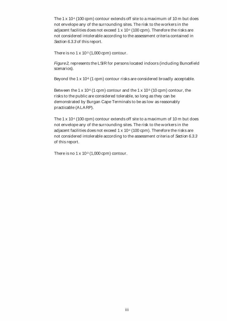
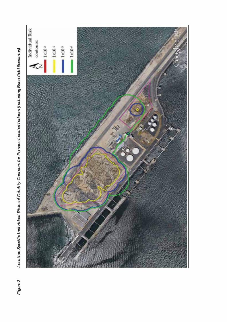
The 1 x 10- (100 cpm) contour extends off site to a maximum of 10 m but does not envelope any of the surrounding sites. The risk to the workers in the adjacent facilities does not exceed 1 x 10- (100 cpm). Therefore the risks are not considered intolerable according to the assessment criteria contained in Section 6.3.3 of this report. There is no 1 x 10⁻³ (1,000 cpm) contour. Figure 2, represents the LSIR for persons located indoors (including Buncefield scenarios). Beyond the 1 x 10⁻⁶ (1 cpm) contour risks are considered broadly acceptable. Between the 1 x 10⁻⁶ (1 cpm) contour and the 1 x 10⁻⁵ (10 cpm) contour, the risks to the public are considered tolerable, so long as they can be demonstrated by Burgan Cape Terminals to be as low as reasonably practicable (ALARP). The 1 x 10- (100 cpm) contour extends off site to a maximum of 10 m but does not envelope any of the surrounding sites. The risk to the workers in the adjacent facilities does not exceed 1 x 10- (100 cpm). Therefore the risks are not considered intolerable according to the assessment criteria of Section 6.3.3 of this report. There is no 1 x 10⁻³ (1,000 cpm) contour.

Figu
re 1
Lo
cati
on S
peci
fic In
divi
dual
Ris
ks o
f Fat
alit
y Co
ntou
rs fo
r Per
sons
Loc
ated
out
door
s (I
nclu
ding
Bun
cefie
ld S
cena
rios
)
Figu
re 2
Lo
cati
on S
peci
fic In
divi
dual
Ris
ks o
f Fat
alit
y Co
ntou
rs fo
r Per
sons
Loc
ated
Indo
ors
(Inc
ludi
ng B
unce
field
Sce
nari
os)

Societal Risk The calculated societal risk results for off-site populations (i.e. excluding known Burgan Cape Terminals on site population) as a result of risks posed by the site including Buncefield type scenarios are shown in Figure 3.
Figure 3 Societal Risk for the Burgan Cape Terminals Off Site Populations – Including Buncefield Scenarios
As illustrated by Figure 3 in the sites current proposal the societal risk F-N curve lies below the ‘Broadly Acceptable’ indicator line and therefore also below the intolerable line with Buncefield Scenarios included. Therefore the risks are not considered intolerable however, they should be reduced to levels which are considered As Low As Reasonably Possible (ALARP). Land Use Planning – Location Specific Individual Risk (LSIR) Figure 4 represents the location specific individual risks (LSIR) of dangerous dose for hypothetical persons located outdoors (including Buncefield type scenarios) for Land Use Planning (LUP). As shown in Figure 4, the risk consultation distance i.e. the 3 x 10⁻⁷ (0.3 cpm contour) measured from the site boundary extends off-site to the west partly enveloping the winch cable store and to the south east of the storage area enveloping the FFS Refineries site as well as over the edge of the mole to the north.
0.01
0.1
1
10
100
1000
10000
1 10 100 1000 10000 100000 1000000
F (c
pm)
N
Burgan CapeTerminalsIntolerable

The middle zone, 1 x 10⁻⁶ (1 cpm) contour follows the same trend as the 3 x 10⁻⁷ (0.3 cpm) contour to the north and partly over the FFS site and Berth 2. The 1 x 10⁻⁵ (10 cpm) inner zone contour extends off site and follows similar trend to the 1 x 10⁻⁶ (1 cpm) contour but a reduced amount towards the north and the area surrounding the road tanker loading gantry. Using the criteria outlined in section 6.3.1 of this report it has been shown that the Burgan Cape Terminals site falls within the ‘Don’t Advise Against DAA’ category for all 3 probability of dangerous dose zones. Restrictions on future development around the site should be enforced based on the LUP criteria explained within the report. Risk contours shown in Figure 4 should be compared against the criteria to deem if any proposed future development falls into the ‘Advise Against AA’ or ‘Don’t Advise Against DAA’ category. If the development falls within the ‘Advise Against AA’ category the proposed development cannot be continued.

Figu
re 4
Lo
cati
on S
peci
fic In
divi
dual
Ris
ks o
f Dan
gero
us D
ose C
onto
urs
– La
nd U
se P
lann
ing

CONCLUSIONS Environmental Resources Management Southern Africa (Pty) Ltd would declare the proposed Burgan Cape Terminals (Pty) Ltd which will be located at Portside Road, Eastern Mole Berth, Western Cape (GPS coordinates in decimal degrees: : ) will be a Major Hazard Installation (MHI) as outlined in the current legislation. As a result of being declared a MHI, the Requirements of the MHI Regulations must be followed completely to ensure the proposed Burgan Cape Terminals site is legally compliant. Copies of this risk assessment must be submitted to the Local Provincial Director of the Department of Labour, the Chief Inspector of the Department of Labour Head Office in Pretoria and the Local Authorities.
CONTENTS
1 INTRODUCTION 1
1.1 GENERAL INTRODUCTION 1 1.2 REQUIREMENTS OF THE MHI REGULATIONS 3
2 RISK ASSESSMENT & MANAGEMENT METHODOLOGY 5
2.1 DEFINITIONS 5 2.2 PROCESS OF RISK MANAGEMENT 5 2.3 HAZARD IDENTIFICATION 7 2.4 CONSEQUENCE ANALYSIS 7 2.4.1 Harm Criteria for Consequence Analysis 7 2.4.2 Consequence Modelling 8 2.5 FREQUENCY OF MAJOR ACCIDENT HAZARDS 9 2.6 RISK CALCULATION 9 2.7 RISK ASSESSMENT 11
3 ENVIRONMENTAL SITE SETTINGS 12
3.1 SITE LOCATION 12 3.2 METEOROLOGY 14 3.3 REQUIREMENTS OF OTHER ENVIRONMENTAL LEGISLATION 15 3.4 ORGANIZATIONAL MEASURES THAT MAY BE REQUIRED 15
4 DESCRIPTION OF FACILITIES 16
4.1 DESCRIPTION OF SITE OPERATIONS 16 4.1.1 Bulk Storage Facilities 16 4.1.2 Ship Offloading Facilities 17 4.1.3 Road Tanker Off-loading (Bridging) Facilities 17 4.1.4 Road Tanker Loading Facilities 17 4.2 MANAGEMENT OF STORAGE TANKS 18 4.3 DESCRIPTION OF PRODUCTS STORED ON SITE 18 4.4 DESCRIPTION OF FIRE FIGHTING FACILITIES 19 4.5 POPULATION DATA 23
5 POTENTIAL MAJOR HAZARDS 25
5.1 INTRODUCTION 25 5.2 POOL FIRES 26 5.3 TANK FIRES 26 5.4 FLASH FIRES 27 5.5 VAPOUR CLOUD EXPLOSIONS 27
6 APPROACH TO THE ASSESSMENT 29
6.1 TERMINOLOGY 29 6.2 HARM CRITERIA 29

6.2.1 Thermal Radiation 29 6.2.2 Buncefield Criteria 31 6.2.3 Flash Fire Flammability Limit 31 6.2.4 Fatality Probabilities 32 6.3 ASSESSMENT CRITERIA 34 6.3.1 Land Use Planning Around Major Hazard Installations 35 6.3.2 Risk Tolerability Criteria 38 6.3.3 Individual Risk of Fatality Criteria 38 6.3.4 Societal Risk Criteria 39 6.4 METHODOLOGY 40
7 RISK ASSESSMENT OF LIQUID FUELS 42
7.1 HAZARD IDENTIFICATION 42 7.1.1 Bulk Storage tank Scenarios 42 7.1.2 Buncefield Scenarios 43 7.1.3 Pipework and Pipeline Scenarios 45 7.1.4 Road Tanker Offloading (Bridging) Scenarios 46 7.1.5 Road Tanker Loading Scenarios 46 7.2 ESTIMATION OF CONSEQUENCES 47 7.2.1 Pool Fires 47 7.2.2 Buncefield Scenarios 49 7.3 ESTIMATION OF INCIDENTS 52 7.3.1 Pool Fire Frequency Calculations 52 7.3.2 Overfill Frequency Calculations 53 7.3.3 Explosion and Flash Fire Frequency Calculations 56
8 RISK ANALYSIS RESULTS 58
8.1 FATALITY RISK CALCULATION 58 8.1.1 Location Specific Individual Risk for the site 58 8.1.2 Societal Risk 63 8.1.3 Rate of Harm (Contributors to the Risk) 65 8.2 ESCALATION EFFECTS 66 8.3 LUP RISK CALCULATION 67
9 NEIGHBOURING MAJOR HAZARDOUS INSTALLATIONS 69
10 EMERGENCY PLANNING 70
10.1 MHI REGULATIONS, SECTION 6 - ON SITE EMERGENCY PLAN 70
11 CONCLUSIONS 72
ANNEX A ERM CERTIFICATES OF ACCREDITATION ANNEX B MHI REGULATIONS ANNEX C MATERIAL SAFETY SHEETS ANNEX D CONSEQUENCE AND FREQUENCY ANALYSIS ANNEX E EMERGENCY RESPONSE PLAN ANNEX F FAULT TREES FOR TANK OVERFILLING

ERM 0305 -BURGAN CAPE TERMINALS MHI V2.0
1
1 INTRODUCTION
1.1 GENERAL INTRODUCTION
A series of major accidents at fuel storage, handling and production facilities have focused worldwide attention on the need to control the design and management of facilities where potential for major accidents exists. In South Africa, the Major Hazard Installation (MHI) Regulations were promulgated on the 16th Act No. 85 of 1993 (1) as amended, to control and manage such activities. The MHI Regulations were revised on 30th July 2001 and under Section 2(1): Scope of Application it states:- “these regulations shall apply to employers, self-employed persons and users, who have on their premises, either permanently, or temporarily, a major hazard installation or a quantity of a substance which may pose a risk, that could affect the health and safety of employees and the public.” A requirement of the MHI Regulations is that a risk assessment needs to be undertaken by an Approved Inspection Authority (AIA), and reviewed at intervals not exceeding five years thereafter. A risk assessment is also required prior to the proposed construction of any major hazard installation. Under Section 3.(1) Notification of Installation of the current legislation states under Notification of Installation:- “Every employer, self-employed person and user, shall notify the chief inspector, provincial director and relevant local government in writing of –
(a) The erection of any installation which will be a major hazard installation, prior to commencement of erection thereof;”
Normally these risk assessments take the form of Quantified Risk Assessments (QRAs). In addition, if there is an incident at an existing site, the facility is also required to revise the MHI Risk Assessment. The MHI Risk Assessment report must be submitted to the Department of Labour and the Local Authorities for review and if necessary, for registration. Environmental Resources Management Southern Africa (Pty) Ltd (hereafter referred to as “ERM”) is accredited by SANAS (certificate no. MHI-0012) and is a Department of Labour Approved Inspection Authority (AIA), No. MHI 0008 for Major Hazard Installation Regulations risk assessments. The certification documents are shown in Annex A. As per the accreditation requirements, this report has been reviewed by an ERM Southern Africa Technical Signatory, namely Gary McFadden.
(1) Regulation R.692 Occupational Health and Safety Act (85/1993): Major Hazard Installation Regulations.

ERM 0305 -BURGAN CAPE TERMINALS MHI V2.0
2
Burgan Cape Terminals (Pty) Ltd wishes to construct a fuel receiving, storage and distribution terminal (hereafter referred to as the “facility” or the “site”) on the Eastern Mole Berth in Cape Town Harbour. It is understood that Burgan Cape Terminals will operate the terminal on behalf of major oil companies. The site is intended to store Petrol and Diesel of various grades as well as additives such as Ethanol and FAME (A Bio Diesel additive) to supplement the petrol and diesel supply. ERM carried out a preliminary Major Hazard Installation Regulations risk assessment for inclusion in the Environmental Impact Assessment which was being undertaken by ERM during entitled Burgan Oil Cape Terminal Major Hazard Installation Risk Assessment for EIA was issued as a specialist study for the EIA on 27th report was completed with the information available at that stage of the project with the intention of carrying out a full MHI risk assessment when the detailed design for the project was finalised. The site will receive fuel from ships and Ethanol and FAME from road tankers. The site will then fill road tankers. It is understood that in the future, Transnet may require a pipeline or pipelines to tie into the existing pipelines running from the Chevron Refinery in Milnerton to the harbour. These links are however not within the scope of this risk assessment and will have to be considered in a separate risk assessment at a later date, when all of the information regarding these lines is available. Burgan Cape Terminals identified the proposed terminal as having the potential to affect the health and safety of employees, as well as members of the public beyond the site boundaries, in the event of a major incident. The aim of the project was to undertake a Quantified Major Hazard Installation (MHI) Risk Assessment of the proposed Burgan Cape Terminals Cape Town Harbour terminal, with the objective to assess the risk to people off-site via the Land Use Planning (LUP) and Fatality approaches. For this report, ERM have used the detailed design information supplied by Burgan Cape Terminals. Any changes to the detailed design considered in this QRA of the site will require a new revision to this MHI risk assessment. ERM have assumed that all equipment on the proposed Burgan Cape Terminals will be designed, constructed, operated and maintained to world class standards and will comply with all relevant South African legislation. The latest approaches and some of the lessons arising from the major accident at Buncefield, UK in December 2005 were considered in the assessment. Until the Buncefield explosion of December 2005, significant vapour cloud explosions involving Petrol were generally not considered credible unless they occurred in heavily congested areas. At Buncefield, a large cloud of vapour was generated when a storage tank was over-filled with petrol over a period of about half an hour.

ERM 0305 -BURGAN CAPE TERMINALS MHI V2.0
3
This vapour cloud was ignited and a powerful explosion occurred causing widespread damage and initiating fires in many adjacent tanks. Research is underway to investigate the Buncefield explosion and there is no currently validated simulation tool that is available to predict overpressures in a similar event. Some UK Health and Safety Executive guidance has been published(1) that gives a method for demonstrating the impact of a Buncefield type event. A similar incident took place in San Juan, Puerto Rico during October 2009 where Petrol storage tanks were being filled from a ship in the harbour. Again one storage tank being filled overflowed and there was a massive explosion. Using the HSE guidance, the Buncefield method has been used within this study. Technical specifications for Burgan Cape Terminals, Cape Town Harbour were gathered during a site visit undertaken by Tim Price of ERM on 21st
as well as conversations with Stijn Willem van Zelst. It should be noted that this site investigation was undertaken only for the purpose of gathering information for this quantified risk assessment and not for the purpose of judging the adequacy of the design, operation or maintenance of the site.
1.2 REQUIREMENTS OF THE MHI REGULATIONS
The specific requirements for undertaking the QRA are set out in Section 5 of the MHI Regulations and are summarised in Table 1.1 (including the relevant section of this report where the requirement has been satisfied). The current Major Hazard Installations Regulations are attached in Annex B.
(1) HSE 2007. Annex 17 - Predictive Assessment ‘Line to take for VCE at Bulk HFL Storage Depots’, Hazardous
Installations Directorate. SPC/Permissioning/11

ERM 0305 -BURGAN CAPE TERMINALS MHI V2.0
Table 1.1 MHI Risk Assessment Requirements
Requirement Corresponding ERM Report Section
(i) a general process description of the major hazard installation Section 4 (ii) a description of the major incidents associated with that type of installation and the consequences of such incidents, which shall include potential incidents
Sections 5, 7.1 and 7.2.
(iii) an estimation of the probability of a major incident Section 7.3 (iv) a copy of the site emergency plan Annex E (v) an estimation of the total result in case of an explosion or fire Section 7.1 (vi) in the case of toxic release, an estimation of concentration effects of such release
N/A
(vii) the potential effect of an incident on a major hazard installation or part thereof on an adjacent major hazard installation or part thereof
Section 9
(viii) the potential effect of a major incident on any other installation, members of the public and residential areas
Section 8
(ix) meteorological tendencies Section 3.2 (x) the suitability of existing emergency procedures for risks identified
Section 10
(xi) any requirements laid down in terms of the Environment Conservation Act 1989
Section 3.3
(xii) any organizational measures that may be required Section 3.4

ERM 0305 -BURGAN CAPE TERMINALS MHI V2.0
5
2 RISK ASSESSMENT & MANAGEMENT METHODOLOGY
2.1 DEFINITIONS
A hazard is defined by the UK Institution of Chemical Engineers (1) (IChemE) as “a physical situation with a potential for human injury, damage to property, damage to the environment or some combination of these. A major hazard is described as an imprecise term for a large scale chemical hazard, especially one which may be realised through an acute event”. A major hazard installation is described in the South African Major Hazard Installation Regulations (2) as “an installation where any substance is produced, processed, used, handled or stored in such a form and quantity that it has the potential to cause a major incident”.
A major incident is defined (2) as “an occurrence of catastrophic proportions, resulting from the use of plant and machinery, or from activities at a workplace”.
The process of hazard identification is described by the IChemE (1) as “the identification of undesired events followed by an analysis of the mechanisms by which undesired events could occur”.
Risk assessment is described (2) as “a process of collecting, organising, analysing, interpreting, communicating and implementing information in order to identify the probable frequency, magnitude and nature of any major incident which could occur at a major hazard installation and the measures needed to be taken to remove, reduce or control potential causes of such incidents”.
2.2 PROCESS OF RISK MANAGEMENT
Risk management has become widely used as a technique to aid decision-making. Five specific elements are involved: 1. Hazard Identification: to determine the incident scenarios, hazards and
hazardous events, their causes and mechanisms.
2. Consequence Analysis: to determine the extent of the consequences of identified hazardous events.
3. Frequency Estimation: to determine the frequency of occurrence of identified hazardous events and the various consequences. Risk Summation: to determine the risk levels.
(1) IChemE (1985). Nomenclature for Hazard and Risk Assessment in the Process Industries. (2) Regulation R.692 Occupational Health and Safety Act (85/1993): Major Hazard Installation Regulations.
ERM 0305 -BURGAN CAPE TERMINALS MHI V2.0
6
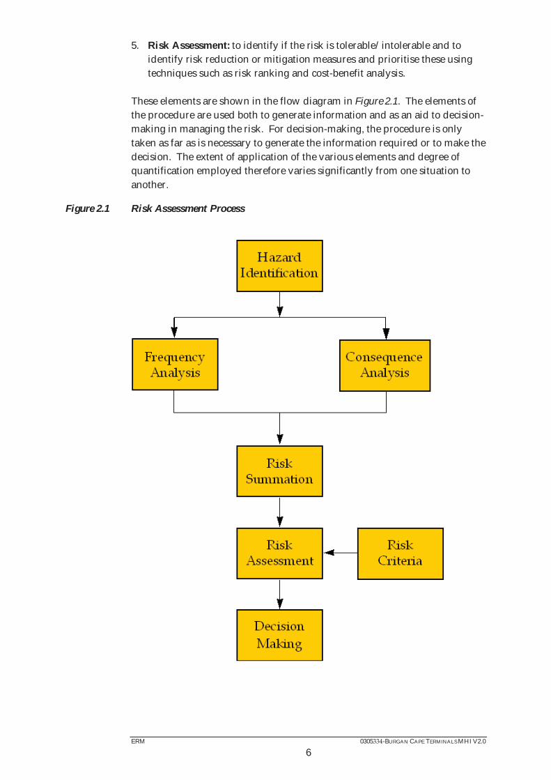
5. Risk Assessment: to identify if the risk is tolerable/intolerable and to identify risk reduction or mitigation measures and prioritise these using techniques such as risk ranking and cost-benefit analysis.
These elements are shown in the flow diagram in Figure 2.1. The elements of the procedure are used both to generate information and as an aid to decision-making in managing the risk. For decision-making, the procedure is only taken as far as is necessary to generate the information required or to make the decision. The extent of application of the various elements and degree of quantification employed therefore varies significantly from one situation to another.
Figure 2.1 Risk Assessment Process

ERM 0305 -BURGAN CAPE TERMINALS MHI V2.0
7
2.3 HAZARD IDENTIFICATION
The first stage in any MHI risk assessment is to identify the potential incidents that could lead to the release of a hazardous material from its normal containment and result in a major accident. This is achieved by a systematic review of the facilities to determine where a release of a hazardous material could occur from various parts of the installation. The major hazards are generally one of three types: flammable, reactive and or toxic. In this study, only flammable hazards are relevant involving loss of containment of diesel, petrol, ethanol and bio Fame. Flammable hazards may manifest as high thermal radiation from fires and overpressures following explosions that may cause direct damage, building collapse, etc. Flammable hazards are present throughout the facility and associated pipelines. Fires may occur if flammable materials are released to the atmosphere and ignition takes place. The possibility of explosions in the instance of over-filling (Buncefield-type incident) has been considered. This study is only concerned with major incident hazards as defined by the scope of the South African Major Hazard Installation Regulations (1). These regulations are concerned only with incidents which involve dangerous substances that give rise to off-site risk as far as the general public and other industries are concerned.
2.4 CONSEQUENCE ANALYSIS
2.4.1 Harm Criteria for Consequence Analysis
During the analysis it is necessary to define harm criteria (or ‘end points’) for use with the consequence models. In the case of this study, these harm criteria are levels of thermal radiation intensity and where relevant, overpressure (in the case of vapour cloud explosions). The derivation of the harm criteria used in this study is described in Section 6.2 of this report.
(1) Regulation R.692 Occupational Health and Safety Act (85/1993): Major Hazard Installation Regulations.

ERM 0305 -BURGAN CAPE TERMINALS MHI V2.0
8
2.4.2 Consequence Modelling
Factors Affecting Consequences
There are several factors which affect the consequences of materials released into the environment. These include (but are not limited to):
Release quantity or release rate Duration of release Initial density of the release Source geometry Source elevation Prevailing atmospheric conditions Surrounding terrain Physical and chemical properties of the material released.
Such factors will affect the consequence zones for the specific hazardous materials, e.g. the distance at which the level of thermal radiation from a fire or overpressure from an explosion has reduced sufficiently so that it is no longer dangerous. Factors Affecting Fire Hazards
When considering large open hydrocarbon fires, the principal hazard is from thermal radiation. The primary concerns are safety of people and potential damage to nearby facilities or equipment. Determination of thermal radiation hazard zones involves the following three steps:
Geometric characterisation of the fire, that is, the determination of the burning rate and the physical dimensions of the fire; Characterisation of the radiative properties of the fire, that is, the determination of the average radiative heat flux from the flame surface; and
Calculation of radiant intensity at a given location.
These, in turn, depend upon the nature of the flammable material, size and type of fire, prevailing atmospheric conditions and the location and orientation of the target/receptor. Consequence Models
The hazards described above can be modelled analytically by standard models used for consequence analysis. Many of these models are performed by computer software and ERM has access to a range of such models. The modelling of event consequences is described in Section 7.2 of this report.

ERM 0305 -BURGAN CAPE TERMINALS MHI V2.0
9
2.5 FREQUENCY OF MAJOR ACCIDENT HAZARDS
For each hazard identified, the frequency is assessed. A simple way of defining the frequency of major accident events within a QRA is to use a ‘top down’ approach. This provides frequencies of the events of interest (fires, explosions, etc.) by reference to historical accident data sources, without considering the causes or development of these events in detail. Alternatively, if more detail is required, a ‘bottom up’ approach may be used, where the frequency of individual release scenarios is considered. The different outcomes that may result from these releases and the associated frequencies are then developed using techniques such as event tree analysis. A release of hazardous material may be considered for a range of hole sizes, which will depend on the various causes considered. For example, a leak from a pipeline due to corrosion will tend to be small, whereas external impact, say, by a mechanical digger, is likely to produce a much larger hole. ERM has obtained a copy of the Planning Case Assessment Guide (PCAG) developed by the UK Health and Safety Executive (HSE). This enables an estimate of the likelihood of potential hazards following the failure of tanks, vessels, process piping, valves, flanges, etc. to be made. The frequency of the various outcomes (accident scenarios) is then estimated by multiplying the frequency of the release by the probability of the various outcomes. In this study, for flammable releases these outcomes are principally pool fires and flammable vapour clouds of various sizes.
2.6 RISK CALCULATION
The individual risk for a specified level of harm is calculated taking the following variables into consideration:
The frequency of the hazardous outcome (consequence), e.g. pool fire event;
The probability that the hazardous outcome (consequence) will reach the location specified (This includes variation of wind direction with consequent change to flame tilt; both downwind and crosswind distances need to be taken into account);
Probability of an individual being at the location;
Probability of escape into shelter by an individual; and

ERM 0305 -BURGAN CAPE TERMINALS MHI V2.0
10
The probability that, given exposure to the hazardous outcome, the person suffers a defined level of harm.
The frequency of harm (fh) being present from each hazardous outcome (consequence) event must be calculated and summed to give the maximum individual risk (IR) from all events at one location.
IR(max) = fh for all consequences As individual risk is location specific, the above process needs to be repeated for each location considered. The individual risk from other facilities can be summed to give the overall individual risk level from several major hazards. Calculation can be avoided if it is obvious that the event would not be able to affect a location e.g. the specified location is too far away. The frequency of harm will be different for differing weather categories and needs to be calculated for each weather category used. The frequency of harm for a given consequence and weather category is expressed as follows: fh = fe x Pw x Pd x Pexp x Pharm Where: fe = frequency of the hazardous outcome (consequence) Pw = probability of that weather category Pd = probability of the wind blowing in the required direction for event to affect the individual (Pd = 0 if event cannot reach a particular location) Pexp = probability of exposure Pharm = probability that defined level of harm results given that exposure has occurred The probability of the wind blowing in the required direction depends on the angle of entrapment, or the circular sector where a particular hazardous outcome encompasses the specified location. This is a function of the distance from the source, the size, and shape of the hazard ‘footprint’. The size and shape of the footprint is determined from the results of the consequence analysis, but gives a complex shape and is correspondingly difficult to calculate the angle of entrapment. These complex shapes are often simplified to regular shapes in order to calculate the angle of entrapment. The frequency of harm for a specific event is the sum of the frequencies of harm for the different weather conditions:
fh = fh,weather i all weathers
ERM 0305 -BURGAN CAPE TERMINALS MHI V2.0
11
The stability category and wind speed combinations used in the study are discussed in Section 3.2. ERM’s proprietary ViewRisk computer software has been used to calculate iso-risk contours, which show the geographical distribution of individual risk of harm to people.
2.7 RISK ASSESSMENT
The final and most significant step in the process is the assessment of the meaning and significance of the calculated risk levels. Risk assessment is a process by which the results of a risk evaluation are used to make judgements, either through relative risk ranking of risk reduction strategies or through comparison with established risk targets (criteria). Where off-site risk criteria relevant to QRA have been issued (in this case based on criteria used in the UK), it is possible to assess the calculated risk levels against these criteria. This determines whether the risks are tolerable, broadly acceptable, or if risk reduction/mitigation measures are required to reduce the risk to levels which can be considered to be as low as reasonably practicable (ALARP). The risk events can then be ranked to determine the relative contribution of each to the overall risk level. In general the higher risk events should be examined for possible areas of reduction or mitigation as a first step. Measures that prevent the potential incident from occurring should be considered first, followed by measures that reduce the probability (e.g. reduction in flanges), then measures that may limit the amount released (e.g. remotely operated valves, ROVs) and finally measures that may reduce the potential consequences (e.g. water sprays). The risk assessment will thus enable decisions to be made on whether an investment should be made on particular mitigation measures so that the risk is effectively managed. The residual risk will then be managed by appropriate safety management systems to ensure safe operations, maintenance, good practice, etc. The risk criteria used in this study are presented in Section 6.3 of this report.
ERM 0305 -BURGAN CAPE TERMINALS MHI V2.0
12
3 ENVIRONMENTAL SITE SETTINGS
3.1 SITE LOCATION
The proposed Burgan Cape Terminals site will be located on Portside Road on the Eastern Mole Berth in the Cape Town Harbour, Western Cape (GPS coordinates in decimal degrees: 33.90988 ). The site is intended to have two primary, separate operating areas. A storage area is located to the north western end of the berth while the road tanker loading gantry is located further to the south east. A bulk heavy oil storage terminal belonging to FFS Refineries (Pty) Ltd is located between the two Burgan Cape Terminals site areas. The two areas are linked by aboveground product pipelines The land-use surrounding the site can be summarised as follows: Both Berth 1 and Berth 2 are located on the south western side of the mole and therefore south west of both the storage tanks and the gantry loading facility. At the end of the mole, between Berth 1 and the proposed storage tanks in Bund B, the winch cable storage building is located. Also located on the mole is the FFS Refineries site which is situated between the proposed Burgan Cape Terminals storage site and road loading gantry bays. FFS Refineries is located on the south west side of the mole with part of the FFS Refineries storage located between the proposed gantry bay and Berth 2. Due to the nature of the harbour and mole design, other industrial sites within the harbour are located outside the largest consequence distance and are therefore judged to be not affected in the event of a major incident at the Burgan Cape Terminals site. Important surrounding sites:
The FFS Refineries storage terminal is an MHI. Major transport routes in close proximity to the site:
Portside Road is the primary access road to the Eastern Mole Berth.
The land-use around the site is shown in Figure 3.1. The following Major Hazard Installations have been identified to be near the site:
FFS Refineries located adjacent to the site

Figu
re 3
.1
Aer
ial M
ap fo
r Bur
gan
Cape
Ter
min
als,
Cap
e To
wn
Har
bour
, Wes
tern
Cap
e

ERM -BURGAN CAPE TERMINALS MHI V2.0
3.2 METEOROLOGY
Typically, quantitative risk assessments (QRAs) require information about the wind speed, wind direction and stability class. Atmospheric stability is difficult to measure and often varies dramatically over relatively short distances. Atmospheric stability classes need to be defined in the dispersion modelling to facilitate estimates of lateral and vertical dispersion parameters. The preferred stability classification scheme for use in air quality modelling applications is the scheme proposed by Pasquill (1961). The Pasquill Stability Classes are defined by the letters A to F and are described as follows: A. Extremely unstable conditions B. Moderately unstable conditions C. Slightly unstable conditions D. Neutral conditions E. Slightly stable conditions F. Moderately stable conditions. Neutral conditions correspond to a vertical temperature gradient of approximately 1 C per 100 m. The meteorological conditions defining Pasquill stability classes are given in Table 3.1:
Table 3.1: Pasquill Stability Classes
Surface Wind Speed (m/s)
Day-time Insulation Night-time Insulation Strong Moderate Slight
<2 A A - B B 2 – 3 A – B B C E F 3 – 5 B B - C C D E 5 – 6 C C - D D D D >6 C D D D D
It is understood that to date no weather stations in South Africa measure both wind speed and stability categories. Since no site-specific weather data were available, meteorological data (i.e. wind and stability data) from the closest weather station, namely Cape Town Airport was sourced from the research report ‘Stability Wind Roses for Southern Africa’ (1) . The average ambient temperature and humidity for Cape Town Harbour were obtained from South African Weather Services. A summary of the data is as follows:
(1) Tyson, P.D. et al,'Stability Wind Roses for Southern Africa', Department of Geography and Environmental Studies,
University of Witwatersrand, 1979.
ERM -BURGAN CAPE TERMINALS MHI V2.0
15
Average ambient temperature is 17 C and average relative humidity 75.5%.
ERM selected the following stability classes and wind speed scenarios for modelling purposes:
B3 – meaning a stability class of B (moderately unstable conditions) where the wind speed is greater than 3 m/s. C8 - meaning a stability class of D (neutral conditions) where the wind speed is greater than 8 m/s.
The above weather scenarios give a conservative daytime weather condition.
F2 – meaning a stability class of F (moderately stable) where the wind speed is less than or equal to 2 m/s. This class is often used by the US Environmental Protection Agency for determining worse case scenarios for vapour cloud dispersion consequence analysis. F2 gives a conservative night time weather condition.
Selecting the above categories gives an average and a ‘worst case’ condition for the risk assessment study.
3.3 REQUIREMENTS OF OTHER ENVIRONMENTAL LEGISLATION
EIA Regulations (GNR 543, 544 and 546 of 18th June 2010) promulgated under the National Environmental Management Act No. 107 of 1998, as amended The project was subjected to an Environmental Impact Assessment in terms of the National Environmental Management Act (Act 107 of 1998, as amended) and associated 2010 EIA Regulations. The project was granted environmental
Regulations, 2010, were authorised. th Environmental Affairs promulgated regulations in terms of Chapter 5 of the National Environmental Management Act in Government Notice No.982, 983,
th Listed
similarly authorized.
3.4 ORGANIZATIONAL MEASURES THAT MAY BE REQUIRED
The organisation in place at the Burgan Cape Terminals site is expected to be commensurate with the level of risk posed by the installations under assessment. This assumes that all personnel will be trained and equipped to carry out the requirements of their position within the organisation and will be declared competent to fulfil their duties.
ERM -BURGAN CAPE TERMINALS MHI V2.0
16
4 DESCRIPTION OF FACILITIES
4.1 DESCRIPTION OF SITE OPERATIONS
The proposed Burgan Cape Terminals installation is intended to receive AGO (Diesel) and ULP (Petrol) from transport tanker ships. Fuel will be offloaded by two Hard Arms on Eastern Mole Berth 2. Ethanol and FAME are intended to supplement the ULP and AGO at the terminal and are added to the fuels in set ratios. Ethanol and FAME will be delivered to the site by road tanker. The products will be pumped from the site storage area through aboveground pipework to the site road tanker loading gantry. Road tankers will then be loaded in any of the six loading bays. Road tanker loading will occur during the day and at night. For this MHI report, ERM have assumed that all equipment on the Burgan Cape Terminals site will be designed, constructed, operated and maintained to world class standards and will comply with all relevant South African legislation.
4.1.1 Bulk Storage Facilities
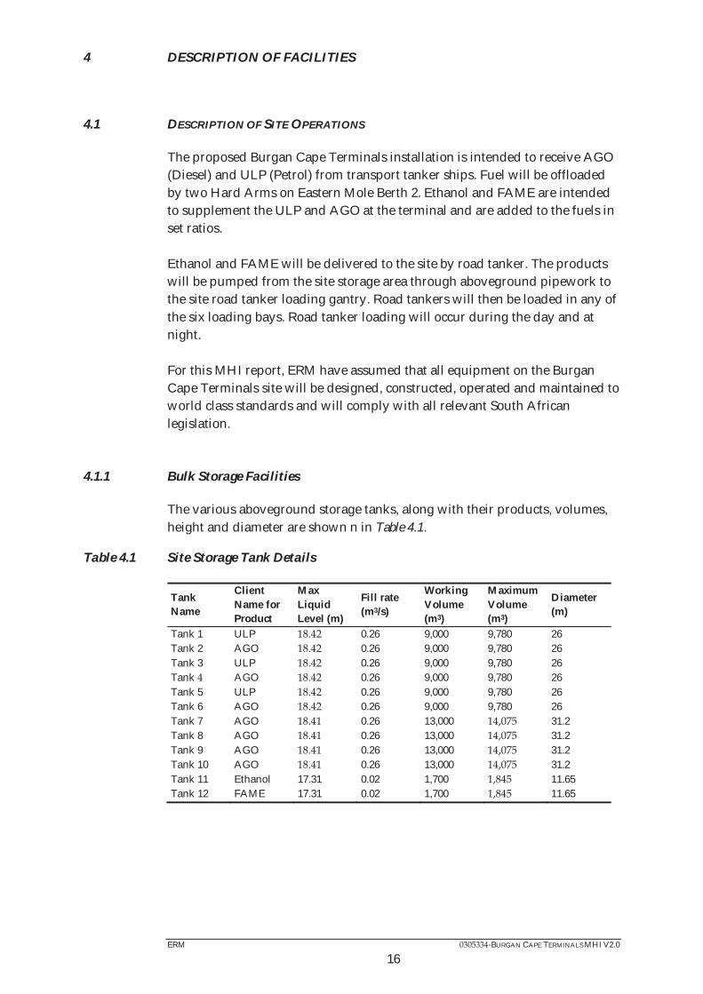
The various aboveground storage tanks, along with their products, volumes, height and diameter are shown n in Table 4.1.
Table 4.1 Site Storage Tank Details
Tank Name
Client Name for Product
Max Liquid Level (m)
Fill rate (m3/s)
Working Volume (m3)
Maximum Volume (m3)
Diameter (m)
Tank 1 ULP 0.26 9,000 9,780 26 Tank 2 AGO 0.26 9,000 9,780 26 Tank 3 ULP 0.26 9,000 9,780 26 Tank AGO 0.26 9,000 9,780 26 Tank 5 ULP 0.26 9,000 9,780 26 Tank 6 AGO 0.26 9,000 9,780 26 Tank 7 AGO 0.26 13,000 31.2 Tank 8 AGO 0.26 13,000 31.2 Tank 9 AGO 0.26 13,000 31.2 Tank 10 AGO 0.26 13,000 31.2 Tank 11 Ethanol 17.31 0.02 1,700 11.65 Tank 12 FAME 17.31 0.02 1,700 11.65
ERM -BURGAN CAPE TERMINALS MHI V2.0
17
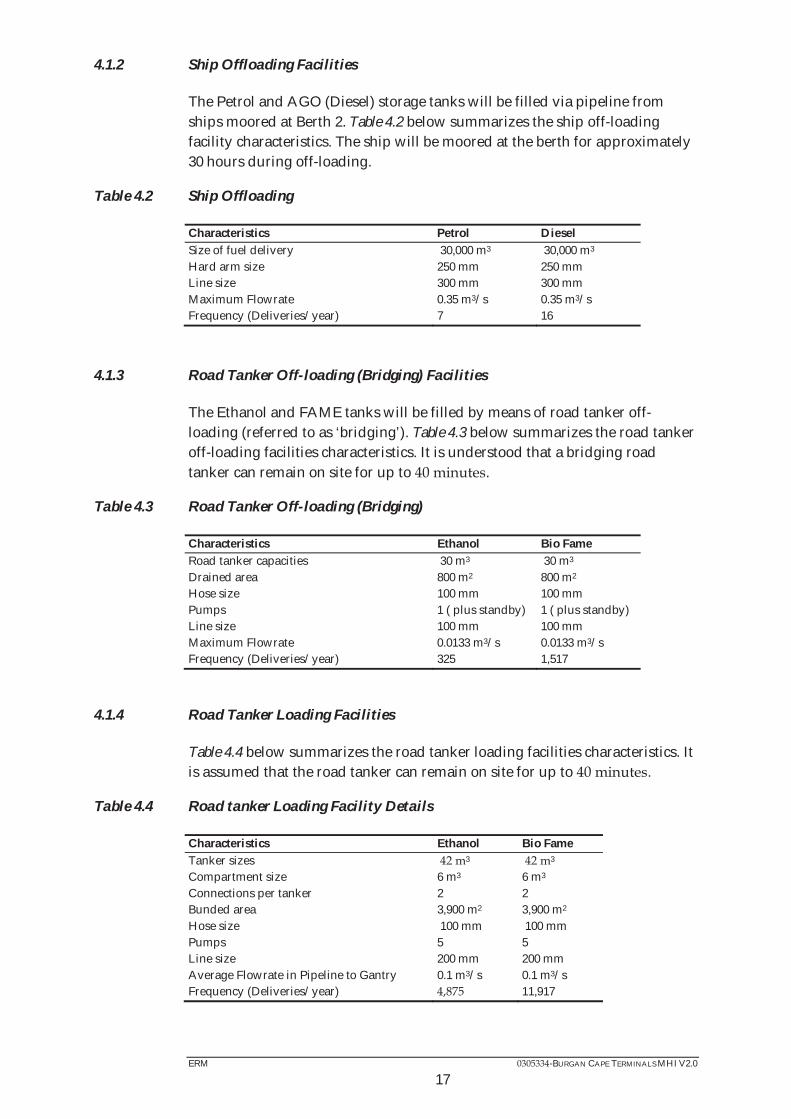
4.1.2 Ship Offloading Facilities
The Petrol and AGO (Diesel) storage tanks will be filled via pipeline from ships moored at Berth 2. Table 4.2 below summarizes the ship off-loading facility characteristics. The ship will be moored at the berth for approximately 30 hours during off-loading.
Table 4.2 Ship Offloading
Characteristics Petrol Diesel Size of fuel delivery 30,000 m3 30,000 m3 Hard arm size 250 mm 250 mm Line size 300 mm 300 mm Maximum Flowrate 0.35 m3/s 0.35 m3/s Frequency (Deliveries/year) 7 16
4.1.3 Road Tanker Off-loading (Bridging) Facilities
The Ethanol and FAME tanks will be filled by means of road tanker off-loading (referred to as ‘bridging’). Table 4.3 below summarizes the road tanker off-loading facilities characteristics. It is understood that a bridging road tanker can remain on site for up to .
Table 4.3 Road Tanker Off-loading (Bridging)
Characteristics Ethanol Bio Fame Road tanker capacities 30 m3 30 m3 Drained area 800 m2 800 m2 Hose size 100 mm 100 mm Pumps 1 ( plus standby) 1 ( plus standby) Line size 100 mm 100 mm Maximum Flowrate 0.0133 m3/s 0.0133 m3/s Frequency (Deliveries/year) 325 1,517
4.1.4 Road Tanker Loading Facilities
Table 4.4 below summarizes the road tanker loading facilities characteristics. It is assumed that the road tanker can remain on site for up to .
Table 4.4 Road tanker Loading Facility Details
Characteristics Ethanol Bio Fame Tanker sizes 3 3 Compartment size 6 m3 6 m3 Connections per tanker 2 2 Bunded area 3,900 m2 3,900 m2 Hose size 100 mm 100 mm Pumps 5 5 Line size 200 mm 200 mm Average Flowrate in Pipeline to Gantry 0.1 m3/s 0.1 m3/s Frequency (Deliveries/year) 11,917

ERM -BURGAN CAPE TERMINALS MHI V2.0
18
4.2 MANAGEMENT OF STORAGE TANKS
For the storage tanks, the storage and movement of fuels at the tank farm will be managed via tank dip reading, and a combination of both manual and automatic tank gauging. All tank management will be undertaken to world class standards and will comply with all relevant South African legislation. The recommendations from the Buncefield incident have also been implemented in the design of the instrumentation on the storage tanks to prevent overfilling. Based on proposed designs, all storage tanks on site will be provided with secondary containment and will be able to contain leaks and spills. Table 4.5 shows the proposed bund sizes with the layout of the bunds shown in Figure 4.1.
Table 4.5 Burgan Cape Terminals, Cape Town Harbour - Bund sizes
ID Containment Name
Containment Type
Gross Area (m2)
Net Area (m2)
Wall Height (m)
Secondary Containment Bunds and Area (m2)
Secondary Containment Wall Height (m)
1 Bund A1 Tank Bund 1,225 1 A2, A3 - 2.8 2 Bund A2 Tank Bund 1,291 760 1 - 2.8 3 Bund A3 Tank Bund 1,202 671 1 2.8
Tank Bund 1,298 767 1 A2, A3, A6 2.8 5 Bund A5 Tank Bund 1,151 620 1 A3, A6 2.8 6 Bund A6 Tank Bund 703 1 2.8 7 Bund B1 Tank Bund 1,935 1170 1 B2, B3 2.8 8 Bund B2 Tank Bund 1,625 860 1 2.8 9 Bund B3 Tank Bund 2,181 1 B1, B2, 2.8 10 Tank Bund 2,199 1 B2, B3 2.8 11 Bund C1 Tank Bund 1 C2 2.8 12 Bund C2 Tank Bund 303 1 C1 2.8 13 Drained Gantry Drained Area 3939 3939 / 2.8
It is understood that all bunds will comply with SANS 10089-1 and that bund sizes and capacities will be appropriate according to the standard(1). It is assumed that the Burgan Cape Terminals installation and all equipment on the site will be designed, constructed, operated and maintained to world class standards and will comply with all relevant South African legislation.
4.3 DESCRIPTION OF PRODUCTS STORED ON SITE
The characteristics of flammable products on site considered for the MHI appear in their respective Material Safety Data Sheets (MSDS). Copies of the MSDS’s are attached as Annex C.
(1) South African National Standard 10089-1 Storage and distribution of petroleum products in above ground bulk

ERM -BURGAN CAPE TERMINALS MHI V2.0
19
4.4 DESCRIPTION OF FIRE FIGHTING FACILITIES
The site will comply with the requirements of Transnet Ports Authority (TPA) and world class best practices and standards such as those published by NFPA, SANS and API. Proposed Fire Protection The Burgan Cape Town Terminals site fire protection will consist of the following: Storage tanks – Fixed foam pourers will be installed to the top of all tanks, fixed spray water nozzles will be installed to the roof of and shell of all tanks in accordance with: NFPA11 & SANS10089-1 Tank Bunds – Fixed bund foam pourers will be positioned around the perimeter of the bunds in accordance with: BSEN-1365-2 Tank Farm and Gantry Yard Area – Firewater and foam hydrants will be positioned around the site perimeter in accordance with: SANS10089-1 & NFPA11 Loading Gantries and Bio-Fuels Offloading Point – The road loading gantries and biofuels will have with foam sprinkler nozzles located in the roof structure in accordance with: NFPA11 Fire Water Supply - The fire fighting system is a fresh water system with water supplied from the ports water mains. The system will have connections available to supply or receive water from the neighbouring sites. The connection size, type and location shall be agreed and confirmed with the Port Authority at detailed design. As a back up to the fresh water supply system, the site will be provided with a sea water pipeline from Transnet National Port Authorities. Fire Water Storage Tank - As prescribed in SANS 10089-1 section 7.8.2 the reserve of fire water available shall accommodate for greatest requirement for fire fighting water for a period of 1 hour. As identified in Section 1.2 2972 m3 of usable fire water storage is required. To fulfil this requirement a 15m diameter x 17m high fire water tank
3 shall be required. The fire water storage tank will be located in Plot 1 opposite the gantries. Fire Water Pumps - Fire water pumps have been sized to suit the requirements of SANS 10089-1. The pumps selected are diesel driven to accommodate the possible loss of electrical power in an emergency situation and will operate in a duty standby arrangement (3 x duty, 1 x standby). The pumps operate at a flow rate of 17,032 litres/ minute (1021.92 m3/hr) and will produce a minimum of 10.0 bar(g). To maintain the pressure within the fire-main (prior to the activation of the main fire pumps) a jockey pump will be required.

ERM -BURGAN CAPE TERMINALS MHI V2.0
20
Fire Water Ring Main - Installation of new pressurised fire water ring main around the tank compound to accommodate at least 150% of calculated flow rate as prescribed
m/sec, should be a minimum of DN300 with laterals DN150. The ring main will be predominantly buried in accordance with SANS 10089 section 7.8.5 and will have 13 DN100 four pillar hydrants located at maximum 90 m centres across the site. The hydrants have been positioned so they can be accesses from the Eastern Mole road and the servitudes that surround the site.
main to allow the isolation of sections of the ring main for maintenance and keep as much as practically possible operational during such times. Tank Cooling -
2 for the tank roof and shell has been determined from Section A.7.1.2.1 of SANS 10089-1. For the purposes of sizing the system been selected for the tank roof cooling requirements and the Angus Fire K20H Water Sprinkler has been selected for the tank shell. If an alternative make/model is used the calculation will need to be revised to meet the requirements of the nozzle and could change the quantity of nozzles required. Due to the radiant heat zones identified in the heat flux calculations the cooling water rings on the tanks are required, these rings are multi-level and have also been segmented into two independent sections. Each multi level section will cover approximately 50% of the tank circumference and arranged in such a way that one or both sections of the cooling ring may be activated depending upon the fire scenario encountered. The tank cooling rings are controlled with the use of on-off solenoid deluge control valves. These valves are remotely activated the control room and will have status feedback via pressure switch for ease of use. There will be one valve for each half tank segment Foam Tank - For the Burgan Cape Terminals site 3 of foam concentrate is required for firefighting. A 100% complete reserve allowance is required (SANS 10089-1 Section 7.8.9) or be available to the terminal within one hour, it is anticipated that the 100% reserve will be required and therefore the total foam requirement is 18.91 m3. The foam tank will be sized to contain only the required foam to fight a fire and the backup supply should be stored in close proximity to the foam tank or in safe location elsewhere on the terminal. Currently the foam system will have connections available to supply or receive foam from the neighbouring sites. The requirement for this shall be agreed and confirmed with the Port Authority at detailed design. Foam Proportioner - A foam proportioner skid will be required (FireDos unit or similar and approved) capable of handling the worst case scenario for foam requirements with the capability of automatic selection of foam concentrate percentage mix (3% & 6%). The selection of foam percentage should be selected from the fire fighting control panel located in the control room. It is anticipated that there will be 1 proportioner that will cover the following systems:
Loading gantries Bund A ring main
ERM -BURGAN CAPE TERMINALS MHI V2.0
21
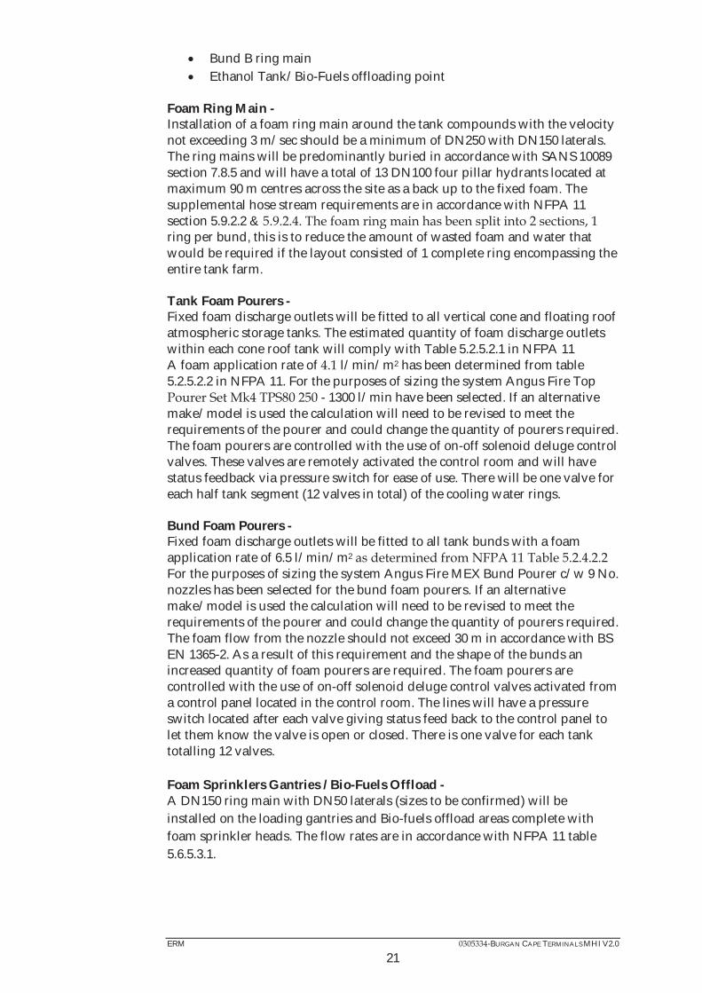
Bund B ring main Ethanol Tank/Bio-Fuels offloading point
Foam Ring Main - Installation of a foam ring main around the tank compounds with the velocity not exceeding 3 m/sec should be a minimum of DN250 with DN150 laterals. The ring mains will be predominantly buried in accordance with SANS 10089 section 7.8.5 and will have a total of 13 DN100 four pillar hydrants located at maximum 90 m centres across the site as a back up to the fixed foam. The supplemental hose stream requirements are in accordance with NFPA 11 section 5.9.2.2 & ring per bund, this is to reduce the amount of wasted foam and water that would be required if the layout consisted of 1 complete ring encompassing the entire tank farm. Tank Foam Pourers - Fixed foam discharge outlets will be fitted to all vertical cone and floating roof atmospheric storage tanks. The estimated quantity of foam discharge outlets within each cone roof tank will comply with Table 5.2.5.2.1 in NFPA 11 A foam application rate of l/min/m2 has been determined from table 5.2.5.2.2 in NFPA 11. For the purposes of sizing the system Angus Fire Top
- 1300 l/min have been selected. If an alternative make/model is used the calculation will need to be revised to meet the requirements of the pourer and could change the quantity of pourers required. The foam pourers are controlled with the use of on-off solenoid deluge control valves. These valves are remotely activated the control room and will have status feedback via pressure switch for ease of use. There will be one valve for each half tank segment (12 valves in total) of the cooling water rings. Bund Foam Pourers - Fixed foam discharge outlets will be fitted to all tank bunds with a foam application rate of 6.5 l/min/m2 For the purposes of sizing the system Angus Fire MEX Bund Pourer c/w 9 No. nozzles has been selected for the bund foam pourers. If an alternative make/model is used the calculation will need to be revised to meet the requirements of the pourer and could change the quantity of pourers required. The foam flow from the nozzle should not exceed 30 m in accordance with BS EN 1365-2. As a result of this requirement and the shape of the bunds an increased quantity of foam pourers are required. The foam pourers are controlled with the use of on-off solenoid deluge control valves activated from a control panel located in the control room. The lines will have a pressure switch located after each valve giving status feed back to the control panel to let them know the valve is open or closed. There is one valve for each tank totalling 12 valves. Foam Sprinklers Gantries / Bio-Fuels Offload - A DN150 ring main with DN50 laterals (sizes to be confirmed) will be installed on the loading gantries and Bio-fuels offload areas complete with foam sprinkler heads. The flow rates are in accordance with NFPA 11 table 5.6.5.3.1.

Figu
re 4
.1
Site
Lay
out W
ith
Bund
s Hig
hlig
hted
for B
urga
n Ca
pe T
erm
inal
s, C
ape
Tow
n H
arbo
ur, W
este
rn C
ape

ERM -BURGAN CAPE TERMINALS MHI V2.0
23
4.5 POPULATION DATA
Both individual and societal risks were addressed in this assessment (refer to Section 6.3). In order to do so, it was necessary to identify average populations at various locations surrounding the sites. A survey of populations of the surrounding areas showed the populations are as described in Table 4.6. These areas are shown in Figure 4.2.
Table 4.6 Population of Areas Surrounding Burgan Cape Terminals, Cape Town Harbour
Area Day Night FFS Refineries 5 (indoors)
25 (outdoors) 0 (indoors) 10 (outdoors)
Other areas where site specific population data was not available were assigned populations based on population densities defined by the TNO Green Book. The population densities for various designations of areas are shown in Table 4.7. It has been concluded that the industrial area ranges between low and medium density (both highlighted in Table 4.7).
Table 4.7 Populations Densities for Areas Surrounding Burgan Cape Terminals, Cape Town Harbour (1)
Type of area Description Population density (persons/ha)
Residential areas/habitats Wildlife area 0 Rural area 1 Sporadic residential development 5 Quiet residential area 25 Busy residential area 70 Urban development with high-rise buildings
120
Industrial areas Personnel density low 5 Medium High 80 Offices – high-rise buildings 200
Recreational areas (in season) Campsite, holiday park 60-200
(1) TNO ‘Green Book’ Methods for the Determination of Possible Damage – CPR 16E – First Addition - 1992
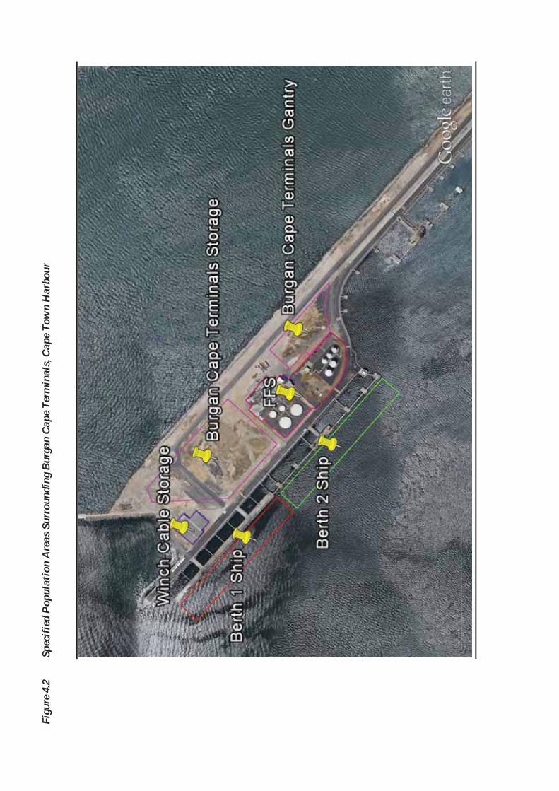
Figu
re 4
.2
Spec
ified
Pop
ulat
ion
Are
as S
urro
undi
ng B
urga
n Ca
pe T
erm
inal
s, C
ape
Tow
n H
arbo
ur
ERM -BURGAN CAPE TERMINALS MHI V2.0
25
5 POTENTIAL MAJOR HAZARDS
This section satisfies the requirements of Section 5 (5) (b) (ii) of the MHI Regulations.
5.1 INTRODUCTION
There are a number of hazards that are present at the proposed Burgan Cape Terminals site that may result in injury to people or a fatality in more serious cases. Some hazards may even give rise to multiple fatalities. This study is only concerned with ‘major hazards’, which are as follows:
Hydrocarbon fires associated with pipework failures Hydrocarbon fires associated with tank failures Storage tank fires Vapour cloud explosions Flash fires.
Each of these hazards is described below. Typically the release of hydrocarbons is associated with the failure of equipment, e.g. a vessel hole or hose breach. The Buncefield accident of 11 December 2005 and the San Juan, Puerto Rico accident of October 2009 indicated that a potentially large flash fire or explosion could result from the overfilling of above ground low flash product storage tanks. The accidents resulted from the prolonged overfill of a petroleum storage tanks in both instances. The Puerto Rico incident occurred when off-loading Petrol from a ship. The excess liquid splashed down the sides of the tanks, breaking up into droplets in both scenarios. This had the effect of enhancing the vaporisation of lighter hydrocarbon fractions in the Petrol, resulting in the generation of large vapour clouds. These clouds spread beyond the site boundaries. The flammable vapour came into contact with an ignition source, at which point the explosions occurred. The Buncefield incident investigation report (1) details certain criteria required for a Buncefield-type accident. These include the tank height (greater than 5 m), the filling rate (greater than 100 m3/hour) and the product stored (with a low flash point, such as Petrol). Several tanks at the proposed Burgan Cape Terminals site exhibit these criteria and therefore Buncefield type scenarios have been investigated for these storage tanks. This study is primarily concerned with ‘major hazards’ giving rise to off-site risk and therefore for this assessment, on site risk has not been considered.
(1) Major Incident Investigation Board (2008).. The Buncefield Incident 11 December 2005. The final report of the Major
Incident Investigation Board. Available at http://www.buncefieldinvestigation.gov.uk/index.htm
ERM -BURGAN CAPE TERMINALS MHI V2.0
26
5.2 POOL FIRES
The principal type of hydrocarbon fire of interest in this study is a pool fire. If a liquid release has time to form a pool and is then ignited before the pool evaporates or drains away, then a pool fire results. Because they are less well aerated, pool fires tend to have lower flame temperatures and produce lower levels of thermal radiation than some other types of fire (such as jet fires); however, this means that they will produce more smoke. Although a pool fire can still lead to structural failure of items within the flame, this will take several times longer than in a jet fire. An additional hazard of pool fires is their ability to move. A burning liquid pool can spread along a horizontal surface or run down a vertical surface to give a running fire. Due to the presence of kerbs, slopes, drains and other obstacles; pool fire areas and directions can be unpredictable. To provide a good conservative model, the pool fires are modelled as perfect circles. For this study, pool-fires have been limited to the following sizes:
Bund size is used for a full bund fire; ¼ of the bund size for small bund fires; and
100 m pool diameter for unconfined fire, reflecting the effect of uneven terrain and containment from curbs and bunds.
For cases where releases are not contained within a bund but within areas with drainage (e.g. road loading gantries), those were considered to limit pool sizes with the area limited by the drainage system.
5.3 TANK FIRES
Ignition at the roof of a conventional atmospheric storage tank will result in a tank fire. One mechanism for the occurrence of a tank fire is considered to be ignition of a flammable vapour – air mixture within the tank vapour space, possibly giving rise to an explosion. Tank fires have not been included in this assessment because, given the height of the tanks, the effect for a person at ground level will be below the harm threshold outside the tank bunds and such the risk is therefore judged to not be significant.

ERM -BURGAN CAPE TERMINALS MHI V2.0
27
5.4 FLASH FIRES
Vapour clouds can be formed from the release of flashing liquids of pressurised flammable material as well as from non-flashing liquid releases where vapour clouds can be formed from the evaporation of liquid pools or from an overfilling of storage tanks or vessels. Where ignition of a release does not occur immediately, a vapour cloud is formed and moves away from the point of origin under the action of the wind. This drifting cloud may undergo delayed ignition if an ignition source is reached, resulting in a flash fire if the cloud ignites in an unconfined area or a vapour cloud explosion (VCE) if within confined area. (An unconfined vapour cloud explosion is also possible under certain conditions). The flash fire is typically modelled through simulating the dispersion of the initial cloud to the lower flammability limit (LFL). The damage area then corresponds to the LFL cloud footprint. It is also possible that pockets of gas capable of igniting travel outside the LFL cloud footprint. Therefore concentrations are also modelled to the half LFL (0.5LFL) level. Flash fires are considered to be possible as a result of overfilling of a storage tank (i.e. a Buncefield-type incident). Guidance on the size of flash fires is given in Section 7.2.2. Vapour from evaporating pools is not considered to result in flash fires due to slower evaporation rates. The cloud typically stays above the liquid pool and does not disperse significantly out of the bund limits. Should vapour be ignited it will most likely initiate a pool fire of the released pool. Pool fire ignition probabilities do take this scenario into consideration.
5.5 VAPOUR CLOUD EXPLOSIONS
If the generation of heat in a fire involving a vapour-air mixture is accompanied by the generation of pressure then the resulting effect is a vapour cloud explosion (VCE). The amount of overpressure produced in a VCE is determined by the reactivity of the gas, the strength of the ignition source, the degree of confinement of the vapour cloud, the number of obstacles in and around the cloud and the location of the point of ignition with respect to the escape path of the expanding gases. In most VCEs the expanding flame front travels more slowly than the pressure wave; this type of explosion is called a deflagration and the maximum overpressure is determined by the expansion ratio of the burning gases. If the flame front travels fast enough to coincide with the pressure wave then the explosion is called a detonation and very severe overpressures can be produced. Detonation is most likely to occur with more reactive gases such as hydrogen and ethylene.

ERM -BURGAN CAPE TERMINALS MHI V2.0
28
VCEs resulting from the overfilling of a tank (i.e. a Buncefield-type incident) have been considered within this assessment. This is due to the criteria having been met for a Buncefield type scenario as outlined in Section 5.1 for a number of the proposed storage tanks on site and the considerations for this explosion scenario are detailed in Section 7.2.
ERM -BURGAN CAPE TERMINALS MHI V2.0
29
6 APPROACH TO THE ASSESSMENT
6.1 TERMINOLOGY
Individual Risk: The frequency at which an individual may be expected to sustain a given level of harm from the realisation of specific hazards. It is a measure of the risk of harm to an individual with defined characteristics at a given point. Maximum Individual Risk: The individual risk to persons exposed to the highest risk in an exposed population. Risk Contours: Lines that connect points of equal risk around the facility or installation (also known as risk iso-lines). Risk Notation: The numerical expression of risk. Risk assessment results involve small numbers and so an exponential notation or a scientific notation is often used. A ‘unit conversion table’ is presented in Table 6.1.
Table 6.1 Risk Notation Conversion Table
Exponential/ scientific
Power Decimal Chance per Million (cpm)
Description
1 E-05/yr 1x10⁻⁵/yr 0.00001/yr 10 cpm 1 in 100 000 per year 1 E-06/yr 1x10⁻⁶/yr 0.000001/yr 1 cpm 1 in million per year 1 E-07/yr 1x10⁻⁷/yr 0.0000001/yr 0.1 cpm 1 in 10 million per year
In this assessment the chance per million (cpm) notation is generally used in figures and graphs.
6.2 HARM CRITERIA
6.2.1 Thermal Radiation
One of the causes for harm to people considered in this study is thermal radiation, which occurs as a result of a fire. The vulnerability of people exposed to thermal radiation depends on the intensity of the incident radiation and the duration of exposure. Thermal flux values are used as criteria for long duration fires such as pool fires as well as jet fires and thermal dose values are used for short duration intense fires such as boiling liquid expanding vapour explosions (BLEVEs) and fireballs.
ERM -BURGAN CAPE TERMINALS MHI V2.0
30
Fatality Criteria
Thermal Flux impact criteria chosen to be used in the fatality assessment have been selected based on the effects of thermal radiation summarised in Lees (1) and have been reproduced in Table 6.2.
Table 6.2 Thermal Flux Impact Criteria For Fatality Assessments (Lees)
Thermal Flux (kW.m-2) Effect 37.5 Intensity at which damage is caused to process equipment 12.5 Intensity at which piloted ignition of wood occurs 6.3 Intensity in areas where emergency actions lasting up to 1
minute may be required without shielding but with protective clothing
The UK HSE has developed criteria based on a research report (2) that used the following relationship to calculate the thermal dose:
3/4tFtdu where
tdu thermal dose units ([kW/m2] ).s T time (s) F Thermal flux (kW/m²)
This report uses the HSE thermal radiation impact criteria for short duration fires that are chosen based on the effects described in Table 6.3.
Table 6.3 Thermal Dose Impact Criteria (HSE)
Thermal Dose (tdu) Effect 1800 50% fatalities among a ‘typical’ population 1000 Dangerous dose to a ‘typical’ population – equates to
approximately 1% fatalities 500 Dangerous dose to a vulnerable / sensitive population
Land Use Planning Criteria
This risk assessment uses 1000 tdu as the dangerous dose criterion for land use planning based on the HSE planning case assessment guide (3) . Assuming that the maximum exposure time is 30 seconds (allowing for exposed persons to escape or find shelter), the thermal flux required to meet the above criteria of 1000 tdu is 13.9 kW/m2. These values for land use planning are summarised in Table 6.4.
(1) Lees F P (2001). Loss Prevention in the Process Industries. 2nd Edition, reprinted with corrections (2) Hymes I, The Physiological Effects of Thermal Radiation, SRD R 275, September, 1983. (3) Planning Case Assessment Guide, 09/07/2002

ERM -BURGAN CAPE TERMINALS MHI V2.0
31
Table 6.4 Thermal Flux Impact Criteria For Land Use Planning Assessments (HSE)
Impact Effect 1000 tdu Dangerous dose to a ‘typical’ population – equates to
approximately 1% fatalities 13.9 (kW.m-2) Intensity to reach a thermal dose of 1000 tdu in 30 seconds
6.2.2 Buncefield Criteria
Buncefield-type events are only considered for tanks that are over 5 m in height and are filled at a rate in excess of 100 m3/h with low flashpoint products (such as Petrol). This is in line with the recommendations of the Buncefield Standards Task Group (BSTG) (1).Table 6.5 shows the specific Buncefield Criteria for Explosions. For this assessment, it has been determined that the Buncefield criteria have only been met for the proposed ULP storage tanks on site and therefore Buncefield scenarios have been included in this assessment for these tanks.
Table 6.5 Buncefield Criteria for Explosions
Buncefield Explosion Effects Fatality Probability People Indoors People Outdoors
200 kPa 1.00 1.00 0.250 kPa 0.00 The various consequences which may arise from a Buncefield-type event are discussed in Section 7.2.2.
6.2.3 Flash Fire Flammability Limit
The extent of a Flash Fire is defined by dispersion of material vapour until the lower flammability limit (LFL) is reached. Within the ½ LFL contour there is still a possibility of fatality due to exposure to burning pockets of vapour. Therefore for the fatality assessment, the dangerous dose end point criteria for flash fires has been designated as the extent to the LFL and half LFL. For land use planning, the dangerous dose end point criteria for flash fires has been designated as the extent to the LFL. The dangerous dose end point criteria for flash fires has been highlighted in Table 6.6.
Table 6.6 Flash Fire Impact Criteria
Criteria Effect
LFL Vapour is able ignite and produce a flash fire ½ LFL Burning pockets of vapour can still occur
(1) http://www.hse.gov.uk/comah/buncefield/bstgfinalreport.pdf

ERM -BURGAN CAPE TERMINALS MHI V2.0
32
6.2.4 Fatality Probabilities
Thermal Radiation
Based on the impact criteria described in Sections 6.2, fatality probabilities have been assigned based on the information below. To assign a probability of fatality to people exposed to the thermal flux values in Table 6.2, probabilities of fatality have been assigned based on the required time to reach thermal doses and the probability of fatality that the HSE has assigned to these thermal doses shown in Table 6.3. Information on the time taken to reach a given thermal dose level at different levels of thermal flux is given in Table 6.7.
Table 6.7 Thermal Dose Impact Criteria
Thermal Flux (kW.m-2)
37.5 8.0 12.5 62.0 17.2 6.3 85.9
-2: For outdoor, a high thermal dosage (1800 tdu) is reached rapidly offering little chance of escape and leaving a high probability of fatality. For indoor, although a building may offer some degree of protection, as 37.5 kW.m-2 is above the spontaneous ignition threshold of wood (1) , there is a high probability that the building will catch fire and force occupants to escape into a higher thermal flux field resulting into a high probability of fatality.
-2: For outdoor, a thermal dose of 1000 tdu is reached after 30 seconds and 1800 tdu after 1 minute, leading to a fatality probability of 1% and 50% respectively. This offers some chance of escape at this level. For indoor, piloted ignition of wood is possible during long exposure at this thermal flux causing a building to catch fire. However, even if the building does ignite, there is still possibility of the occupants escaping to alternative shelter. At a thermal flux of 6.3 kW.m-2: For outdoor, a thermal dose of 1500 tdu is reached after 1.5 minutes seconds and 1800 tdu after 2.5 minutes, leading to a fatality probability of 1% and 50% respectively. This offers a chance of escape resulting in a low fatality.
(1) Lees F P (2001). Loss Prevention in the Process Industries. 2nd Edition, reprinted with corrections

ERM -BURGAN CAPE TERMINALS MHI V2.0
33
For indoor, thermal flux levels are below the piloted ignition threshold for wood and therefore the likelihood of fatality for building occupants is considered to be very low. Therefore the probabilities of Fatality are assigned as presented in Table 6.8.
Table 6.8 Fatality Probability for Thermal Effects
Thermal Effects Fatality Probability People Indoors People Outdoors
Pool fire or Jet fire, Flux > 37.5 kW/m2 (or within flame boundary if not reached); Fireball, Dose> 1800 tdu (or within flame boundary if not reached);
0.80 1.00
Pool fire or jet fire, 37.5 kW/m2 / flame < Flux < 12.5 kW/m2; Fireball, 1800 / Flame< Dose < 1000 tdu
0.25 0.50
Pool fire or jet fire, 12.5 kW/m2 < Flux < 6.3 kW/m2; Fireball, 500 < Dose < 1000 tdu
0.00 0.05
Flash Fires People outdoors within the LFL envelope will be enveloped by the flash fire and are assumed to be fatally injured. Within the 0.5LFL contour, exposure to burning pockets of vapour is possible, leading to a fatality. A probability of 0.2 is to be assigned in this instance. For people indoors, contact with the flame might result in ignition of an engulfed building, endangering occupants. A fatality probability of 0.3 is assigned within the LFL envelope. Beyond the LFL boundary, the likelihood of fatality for persons indoors is considered to be very low.
Table 6.9 Summary of Fatality Probabilities
Impact Fatality Probability People Indoors People Outdoors
Thermal Effects Pool fire or Jet fire, Flux > 37.5 kW/m2 (or within flame boundary if not reached); Fireball, Dose> 1800 tdu (or within flame boundary if not reached);
0.80 1.00
Pool fire or jet fire, 37.5 kW/m2 / flame < Flux < 12.5 kW/m2; Fireball, 1800 / Flame< Dose < 1000 tdu
0.25 0.50
Pool fire or jet fire, 12.5 kW/m2 < Flux < 6.3 kW/m2; Fireball, 500 < Dose < 1000 tdu
0.00 0.05
Buncefield Explosion Effects 200 kPa 1.00 1.00 0.250 kPa 0.00 Flash Fire Effects LFL 0.30 1.00 0.5LFL 0.00 0.20
ERM -BURGAN CAPE TERMINALS MHI V2.0
6.3 ASSESSMENT CRITERIA
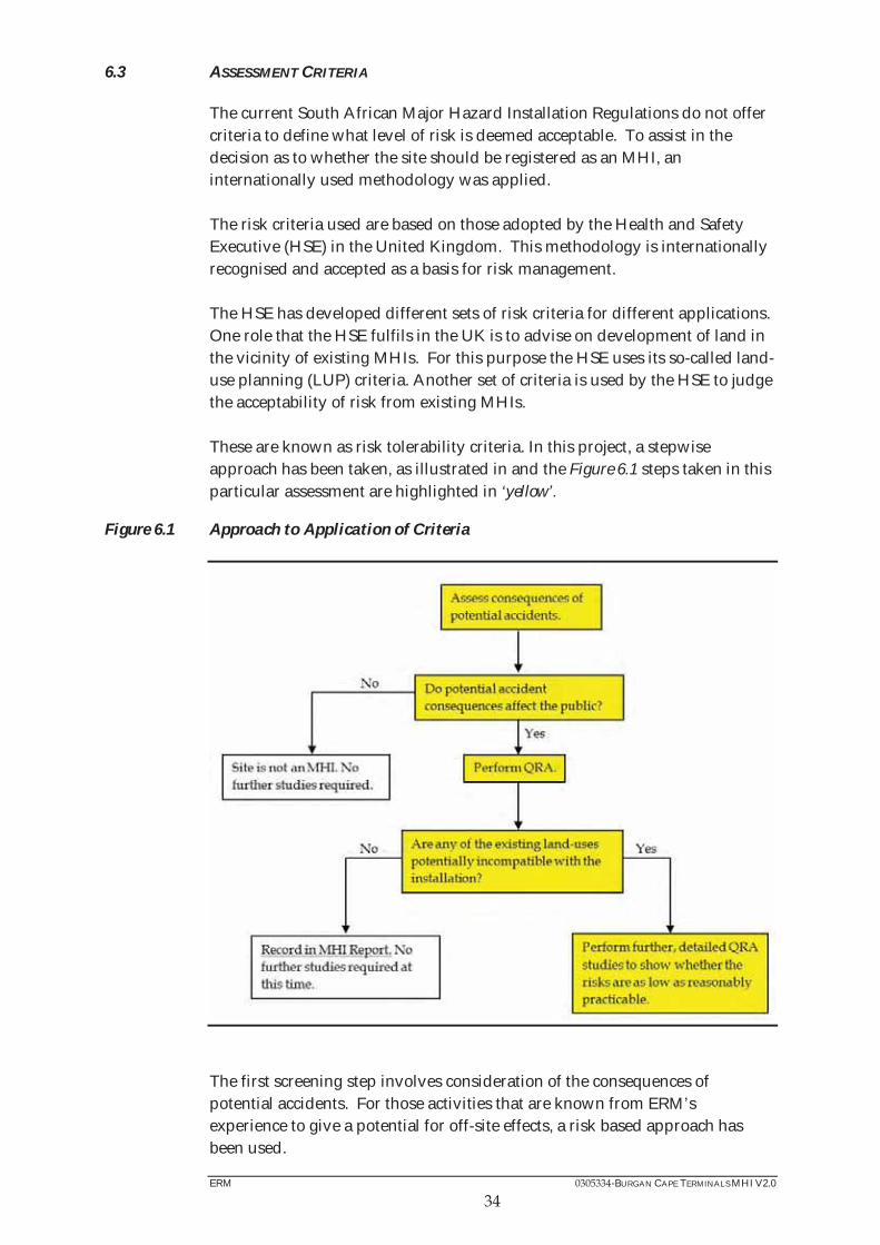
The current South African Major Hazard Installation Regulations do not offer criteria to define what level of risk is deemed acceptable. To assist in the decision as to whether the site should be registered as an MHI, an internationally used methodology was applied. The risk criteria used are based on those adopted by the Health and Safety Executive (HSE) in the United Kingdom. This methodology is internationally recognised and accepted as a basis for risk management. The HSE has developed different sets of risk criteria for different applications. One role that the HSE fulfils in the UK is to advise on development of land in the vicinity of existing MHIs. For this purpose the HSE uses its so-called land-use planning (LUP) criteria. Another set of criteria is used by the HSE to judge the acceptability of risk from existing MHIs. These are known as risk tolerability criteria. In this project, a stepwise approach has been taken, as illustrated in and the Figure 6.1 steps taken in this particular assessment are highlighted in ‘yellow’.
Figure 6.1 Approach to Application of Criteria
The first screening step involves consideration of the consequences of potential accidents. For those activities that are known from ERM’s experience to give a potential for off-site effects, a risk based approach has been used.
ERM -BURGAN CAPE TERMINALS MHI V2.0
35
Where it is not clear whether an activity has the potential for an off-site effect or not, a screening analysis is performed which determines the distance to dangerous dose (1% fatalities) for worst case events. The results are used to determine whether accidents involving that activity can have an impact on members of the public beyond the site boundaries. Where there is the potential to affect members of the public, then further risk calculations were undertaken. The risk calculation incorporates both the consequences of potential accidents and the associated likelihood (frequency). In this study, the end-point used has been ‘dangerous dose’. Exposure to a dangerous dose results in 1% fatalities in a typical population. Risks are measured in chances per million per year (cpm) of an individual receiving a dangerous dose or worse. Another screening test is then applied to see whether further risk studies are necessary. This test involves application of the HSE land-use planning criteria, which compare the nature of the surrounding land-use with the risks produced by the MHI. This test is used to judge whether further, detailed risk assessment studies and application of the risk tolerability criteria would be appropriate. This is explained further in Section 6.3.1.
6.3.1 Land Use Planning Around Major Hazard Installations
A number of countries have well developed approaches to land-use planning around Major Hazard Installations, being either primarily probabilistic (i.e. risk based) or deterministic (i.e. consequence based). The purpose of such systems is to prevent the growth of incompatible land-uses around major hazard sites, or the location of new major hazard sites in inappropriate locations. An overview of the approach used by the UK HSE is given below (1): A three zone system is applied - inner zone, middle zone and outer zone with the outermost extent of the outer zone referred to as the Consultation Distance (CD). In combination with this, land-uses are classified according to sensitivity level, with Sensitivity Level 1 (typically places of work) being the least
most sensitive. A set of rules (in the form of a ‘decision matrix’) is applied to determine which land-uses are appropriate for which zones. In practice, the zones are related to the risk of an individual being exposed to a dangerous dose or load which would “...cause severe distress to almost everyone, many [would] require medical treatment, some [would] be seriously injured and highly vulnerable people might be killed”. This approach appreciates the general public’s aversion not only to fatality but also to injury and other distress (i.e. the concept of harm) - and is distinct from approaches solely related to fatality.
(1) Davies. P., Land-use Planning in the Vicinity of Major Hazard Installations www.hazardview.com, ERM Risk

ERM -BURGAN CAPE TERMINALS MHI V2.0
36
Proposals for new developments in the vicinity of MHIs are assessed by the authorities. Different types of developments are assigned to different ‘sensitivity levels’, with schools and hospitals being amongst the most sensitive; and factories the least sensitive. The authorities recommend that a proposed development does not proceed if the level of risk is above the value that has been established for developments of that type. Similar approaches may be used for new hazardous installations in developed areas. The extent of the three zones may be determined by either a probabilistic assessment (i.e. on a risk basis) or by performing a consequence assessment (i.e. on a ‘protection’ basis). For this study, the extent of each zone is based on probabilistic assessment, taking account of, inter alia:
control measures; frequency of events; event duration; weather conditions; specified harm criteria; and likelihood of exposure.
In the absence of ‘official’ South African guidance, the risk levels applied in this assessment are those employed by the UK Health and Safety Executive (HSE) when setting zones around MHIs. The zones for an annual individual being harmed from exposure to flame/heat, explosion overpressure, toxic gas or asphyxiant (i.e. a specified frequency of receiving a dangerous dose); have been set to correspond to the following risk levels:
inner zone - 10 chances per million per year (1 x 10⁻⁵); middle zone - 1 chance per million per year (1 x 10⁻⁶); and
outer zone (Consultation Distance) - 0.3 chances per million per year (3 x 10⁻⁷).
In November 2001 the UK HSE modified its zoning criteria. This is summarised in Table 5.2, with proposed developments categorised as either ‘advise against’ (AA) or ‘don’t advise against’ (DAA). This refers to the advice the HSE would give to the local authority in relation to a development proposal of a given type in the vicinity of a MHI. For example, the HSE would advise the local authority against building of a new housing development in the inner zone.

ERM -BURGAN CAPE TERMINALS MHI V2.0
37
Table 6.10 Land-use Sensitivity to Risk
Level of Sensitivity Inner Zone
Middle Zone
Outer Zone
1. The normal working public DAA DAA DAA 2. The general public at home AA DAA DAA 3. Vulnerable members of the public (schools, hospitals, etc.) AA AA DAA
recreational areas) AA AA AA
Note that some types of development can change Sensitivity Level depending on their size. For example, large industrial / office land-uses (for more than 100 persons) would move up a Sensitivity Level from Sensitivity Level 1 to Sensitivity Level 2. It should also be noted that HSE does not apply these criteria retrospectively to existing land-use around existing MHIs. This is because the cost of turning down proposals for a development that does not yet exist is much lower than the costs involved in relocating existing land-uses. For example, the costs involved in relocating the occupants of houses in a residential area to new housing elsewhere would be very large compared to the cost of turning down a similar development before it is built. For this reason the land-use planning risk criteria are somewhat more stringent than the criteria applied to existing MHIs. As stated above, the HSE uses these criteria to consider the suitability of proposed, new land-uses in the vicinity of an existing MHI. In this study, the criteria have been used as a screening step to judge whether further risk assessment studies would be appropriate. Where land-uses are identified that would be advised against if they were submitted as new applications, this is used to indicate that further risk studies, potentially with application of risk reduction measures at the site, are required to show that the risks are as low as reasonably practicable (ALARP). Land-uses that would be advised against if they were proposed as new applications are termed ‘potentially incompatible’. The presence of potentially incompatible land-uses does not necessarily mean that the risks from the MHI are intolerable. It simply means that further studies would be worthwhile to determine whether or not more needs to be done to reduce the risk. If no potential incompatibilities are identified, then further, more detailed risk analyses would not be considered necessary at this time. In this assessment it was found that the consequences could extend off-site and affect members of the public. Further calculations were undertaken to show whether the risks can be considered to be as low as reasonable practicable.

ERM -BURGAN CAPE TERMINALS MHI V2.0
38
6.3.2 Risk Tolerability Criteria
The HSE risk tolerability criteria are used to judge the acceptability of the risks from existing MHIs. In the HSE tolerability of risk framework (1), risk levels are divided into three bands of increasing risk, as shown in Figure 6.2 In the lowest band, within the ‘broadly acceptable’ region, the risk is considered to be insignificant and adequately controlled. Risks that are within the ‘unacceptable’ level fall into the uppermost band. In such cases, either action should be taken to reduce the risk levels, or the activity giving rise to the risk should be halted. Between the unacceptable and broadly acceptable regions the risk is considered to be tolerable if it is as low as reasonably practicable (ALARP). The risk is ALARP when the cost of any further risk reduction measures would be grossly disproportionate to (i.e. much greater than) the benefits gained. This is demonstrated in Figure 6.2.
Figure 6.2 HSE Risk Criteria Framework
6.3.3 Individual Risk of Fatality Criteria
The individual risk is the risk to which a hypothetical person (usually with defined characteristics and behaviour pattern) is exposed. The HSE criteria (2) are stated in terms of individual risk of fatality for two types of hypothetical person: a person who is engaged in the industrial activity under consideration (e.g. an employee); and, a person who is not involved in the activity (e.g. a member of the public).
(1) HSE (2001). Reducing Risks, Protecting People. HSE Books, C100. (2) HSE (2001). Reducing Risks, Protecting People. HSE Books, C100.

ERM -BURGAN CAPE TERMINALS MHI V2.0
39
The HSE has provided individual risk values corresponding to the boundaries between the different regions indicated in Figure 6.2. These are summarised in Table 6.11.
Table 6.11 Individual Risk Criteria
Level Individual Risk to Personnel Engaged in the Activity (/yr)
Individual Risk to People not Engaged in the Activity (/yr)
Unacceptable Greater than 1 in 1,000 (10-3) Greater than 1 in 10,000 (10- ) Broadly Acceptable
No greater than 1 in 1,000,000 (10-6) No greater than 1 in 1,000,000 (10-6)
6.3.4 Societal Risk Criteria
Societal risk can be considered a measure of society’s aversion to accidents with multiple fatalities and/or injuries and should be calculated where large numbers of people may be exposed to individual hazards. With regard to societal risk, the UK Health and Safety Executive (HSE) document (1) states that: “…the risk of an accident causing the death of 50 people or more in a single event should be regarded as intolerable if the frequency is estimated to be more than one in five thousand per annum.” This gives a criterion ‘point’ from which intolerable, tolerable and broadly acceptable regions can be extrapolated when considered in conjunction with individual risk criteria. It should be noted that:
Taken in context, the criterion refers to fatalities among members of the public from accidents at a ‘single major industrial activity’; and The criterion appears to be referring to a cumulative frequency (since it refers to ’50 people or more’) rather than the single value associated with a single release outcome.
With this in mind, the following extrapolations have been performed:
The criterion for workers at the site is taken to be ten times higher than that for members of the public, i.e. – the risk of an accident causing the death of 50 workers or more should be regarded as intolerable if the frequency is greater than one in five hundred per annum; The broadly acceptable region is taken to be two orders of magnitude lower than the criterion point for members of the public, i.e. - risk of an Accident causing the death of 50 people or more is taken to be broadly acceptable if the estimated frequency is less than one in 500,000 per annum; and

ERM -BURGAN CAPE TERMINALS MHI V2.0
Each individual point is plotted on a graph and criterion lines extrapolated through them, to give the Cumulative Frequency (F) – Number of Fatality (N) criteria lines shown in Figure 6.3.
Figure 6.3 Cumulative F-N Criteria Lines
6.4 METHODOLOGY
The source term and thermal radiation analyses were undertaken using the DNV Phast v6.6 package. This package has been developed by DNV and has been used extensively globally for modelling such incidents. The software package integrates a suite of programmes to perform consequence calculations related to release events and quantifies the resulting hazardous effects and calculates the impact at a specified distance or target. The ViewRisk risk summation package (developed by ERM) was used for the summation, analysis and presentation of risks related to the installations. The results from the consequence analysis were used as inputs to calculate risks for every scenario. Consequence dimensions are expressed in terms of a number of parameters as illustrated in Figure 6.4.
1.00E-07
1.00E-06
1.00E-05
1.00E-04
1.00E-03
1.00E-02
1.00E-01
1.00E+00
1 10 100 1000
Number of Fatalities
Freq
uenc
y (/y
)
Intolerable (Public) Broadly Acceptable Intolerable (Workers)

ERM -BURGAN CAPE TERMINALS MHI V2.0
Figure 6.4 Harm Envelope Dimension Parameters

ERM -BURGAN CAPE TERMINALS MHI V2.0
7 RISK ASSESSMENT OF LIQUID FUELS
7.1 HAZARD IDENTIFICATION
The main hazards associated with the storage and handling of fuels are pool fires resulting from the ignition of released material as well as explosions and flash fires resulting from the ignition of a flammable cloud formed in the event of tank overfilling. The hazards may be realised following tank overfilling and leaks/failures in the storage tank and ancillary equipment such as transfer pumps, metering equipment, pipelines etc all of which can release significant quantities of flammable material on failure. Section 5 previously provided an explanation of the events which may occur as a result of release of flammable material, followed by ignition.
7.1.1 Bulk Storage tank Scenarios
In addition to overfill, the scenarios considered for the storage tanks were partial/local failures and cold catastrophic failures. Factors that have been identified as having an effect on the integrity of tanks are related to design, inspection, maintenance, and corrosion (1).
The following representative scenarios for the tanks were considered:
Catastrophic failure with release of the entire storage content of the tank. It was assumed that 50% of the tank volume would overtop the bund; Failure of the tank with release resulting in a quarter of the bund surface (or the intermediate bund where applicable) being covered; and
Failure of the tanks with release resulting in the entire bund being covered with product.
Catastrophic failure of a full tank is considered as being the ‘worst case’ scenario and would result in the loss of the entire tank contents within one minute. It is assumed that the bund could fail or be overtopped on catastrophic release of tank content given that the sudden release of large quantities of liquid can form a powerful wave which could damage or surge over the walls. Therefore, for pool fire calculation purposes, it was assumed that 50% of the tank contents overtops the bund. An effective pool diameter (2) is calculated from the sum of the surface areas of the bund and the unconfined pool created from half the tank contents overtopping the bund.
(1) AEA Technology, HSE Guidance Document (2) The equivalent diameter is that of a circle whose surface area is equal to that of the pools.

ERM -BURGAN CAPE TERMINALS MHI V2.0
The unconfined pool diameter was assumed not to exceed 100 m, to provide for the presence of kerbs, slopes, drains and other obstacles.
7.1.2 Buncefield Scenarios
Following an overfilling of a tank with light petroleum products such as Petrol, the Buncefield and San Juan, Puerto Rico incidents show that 3 types of events can happen depending on the weather and surroundings conditions. Explosion Consequences
Guidance from the Process Safety Leadership Group (1) suggests that the overpressures listed in Table 7.1 and illustrated in Figure 7.1 should be used to characterise overpressures from this type of event.
Table 7.1 Overpressure Zones
Zone Name Zone Size (Measured from the tank Wall)
Comment
A r < 250 m HSE research report RR718 on the Buncefield explosion mechanism indicates that over-pressures within the flammable cloud may have exceeded 2 bar (200 kPa) up to 250 m from the tank that overflowed (see Figure 11 in RR718). Therefore within Zone A the probability of fatality should be taken as 1.0 due to over-pressure and thermal effects unless the exposed person is within a protective building specifically designed to withstand this kind of event.
B 250 m < Within Zone B there is a low likelihood of fatality as the over-pressure is assumed to decay rapidly at the edge of the cloud. The expected over-pressures within Zone B are 5 – 25 kPa (see RR718 for further information on overpressures). Within Zone B occupants of buildings that are not designed for potential overpressures are more vulnerable than those in the open air.
C Within Zone C the probability of fatality of a typical population can be assumed to be zero. The probability of fatality for members of a sensitive population can be assumed to be low.
This is further illustrated in Figure 7.1.
(1) Safety and environmental standards for fuel storage sites - Process Safety Leadership Group - Final Report, to be
published December 2009
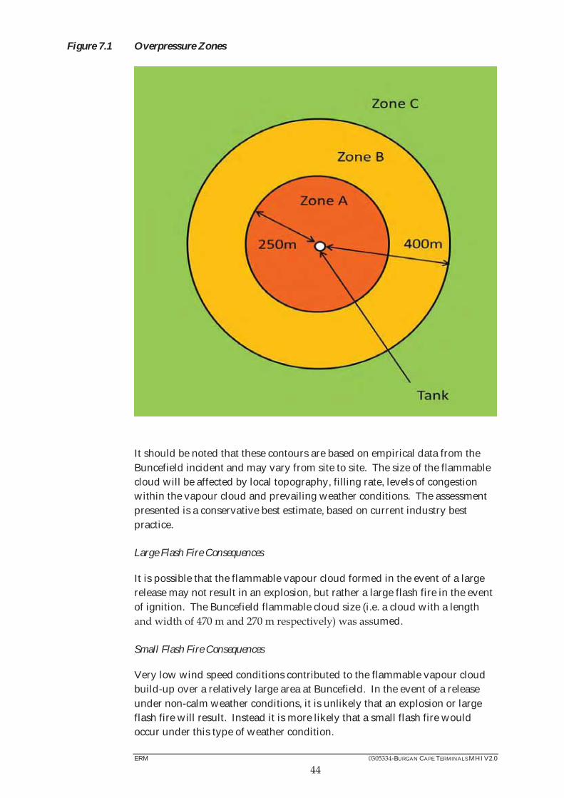
ERM -BURGAN CAPE TERMINALS MHI V2.0
Figure 7.1 Overpressure Zones
It should be noted that these contours are based on empirical data from the Buncefield incident and may vary from site to site. The size of the flammable cloud will be affected by local topography, filling rate, levels of congestion within the vapour cloud and prevailing weather conditions. The assessment presented is a conservative best estimate, based on current industry best practice. Large Flash Fire Consequences
It is possible that the flammable vapour cloud formed in the event of a large release may not result in an explosion, but rather a large flash fire in the event of ignition. The Buncefield flammable cloud size (i.e. a cloud with a length
umed. Small Flash Fire Consequences
Very low wind speed conditions contributed to the flammable vapour cloud build-up over a relatively large area at Buncefield. In the event of a release under non-calm weather conditions, it is unlikely that an explosion or large flash fire will result. Instead it is more likely that a small flash fire would occur under this type of weather condition.

ERM -BURGAN CAPE TERMINALS MHI V2.0
To determine the extent of a small flash fire during non-calm weather conditions, it was assumed that 20% of the spilled product is vaporised and will disperse. This was modelled using 20% of the maximum fill rate. The flash fire is modelled through simulating the dispersion of the initial cloud to the lower flammability limit (LFL). The damage area then corresponds to the LFL cloud footprint.
7.1.3 Pipework and Pipeline Scenarios
The following representative scenarios for the pipework and pipelines were considered:
Depending on the diameter of the pipe, release from holes having diameters as indicated in Section 7.3.1; Pump failure with the failure equivalent to the full bore failure of the outlet pipe; and
Flange failure with the failure equivalent to that of a 13 mm diameter hole in the pipe.
It was assumed that failures of pipework inside the tank bunds would result in a bund fire. It is understood that all of the pipework on-site used to transfer product to the storage tanks pass through bund walls. Therefore, when the product is transferred from a pump to a tank, a release resulting from the rupture of this pipework will be driven by both the liquid head in the tank (since the pipework used for tank filling enters near the base of the tanks) as well as the pump. For releases from pipework attached to the storage tanks, it is understood that the valves on the tank outlets would be closed manually. In the event of a release and assuming that the operator will react efficiently, it is assumed that the manually operated valves would be closed within 20 minutes, limiting the release of product from the storage tanks. It is understood that all of the pumps on site can be shutdown using an emergency stop button. Therefore, in the instance of a release from pipework downstream of a pump and assuming that the operator will react efficiently, the pump is assumed to be shutdown within 10 minutes. Generally release rates for this assessment have been taken equal to the initial release rates. Where the flow through a pipe is driven by a pump, the maximum flow rate arising from a leak is set to 150% of the normal flow rate to allow for pump over-speed. The full list of scenarios investigated the failures and the resulting source releases are given in Annex D.
ERM -BURGAN CAPE TERMINALS MHI V2.0
7.1.4 Road Tanker Offloading (Bridging) Scenarios
For offloading scenarios, generally release rates for this assessment have been taken equal to the initial release rates. Where the flow through a hose is driven by a pump, the maximum flow rate arising from a leak was set to 150% of the normal flow rate to allow for pump over-speed. The following representative scenarios for road tanker offloading are considered:
Catastrophic failure with release of the entire storage contents of the road tanker; Hose connection failures:
- Guillotine hose breach - 15 mm hole in the offloading hose - 5 mm hole in the offloading hose
Hard arm connection failures:
- Hard arm Guillotine - Hole in hard arm with diameter equivalent to 10% of hard arm
diameter Where tanker operations occur, the area was considered to be surrounded by a low pavement wall however the entire road area is also drained, limiting the potential size of leaks in the area. Connection failures for scenarios are assumed to result in a pool confined only by the low pavement area. The released volume in these scenarios is taken as the volume of the road tanker and due to the presence of an operator during offloading the release time is limited to 5 minutes and the frequencies are discussed in Section 4.1.3.
7.1.5 Road Tanker Loading Scenarios
For offloading scenarios, generally release rates for this assessment have been taken equal to the initial release rates. Where the flow through a hose is driven by a pump, the maximum flow rate arising from a leak was set to 150% of the normal flow rate to allow for pump over-speed. The following representative scenarios for the tankers loading are considered:
Catastrophic failure with release of the entire storage contents of the tanker; Guillotine hose breach;
15 mm hole in the offloading hose; and
5 mm hole in the offloading hose.
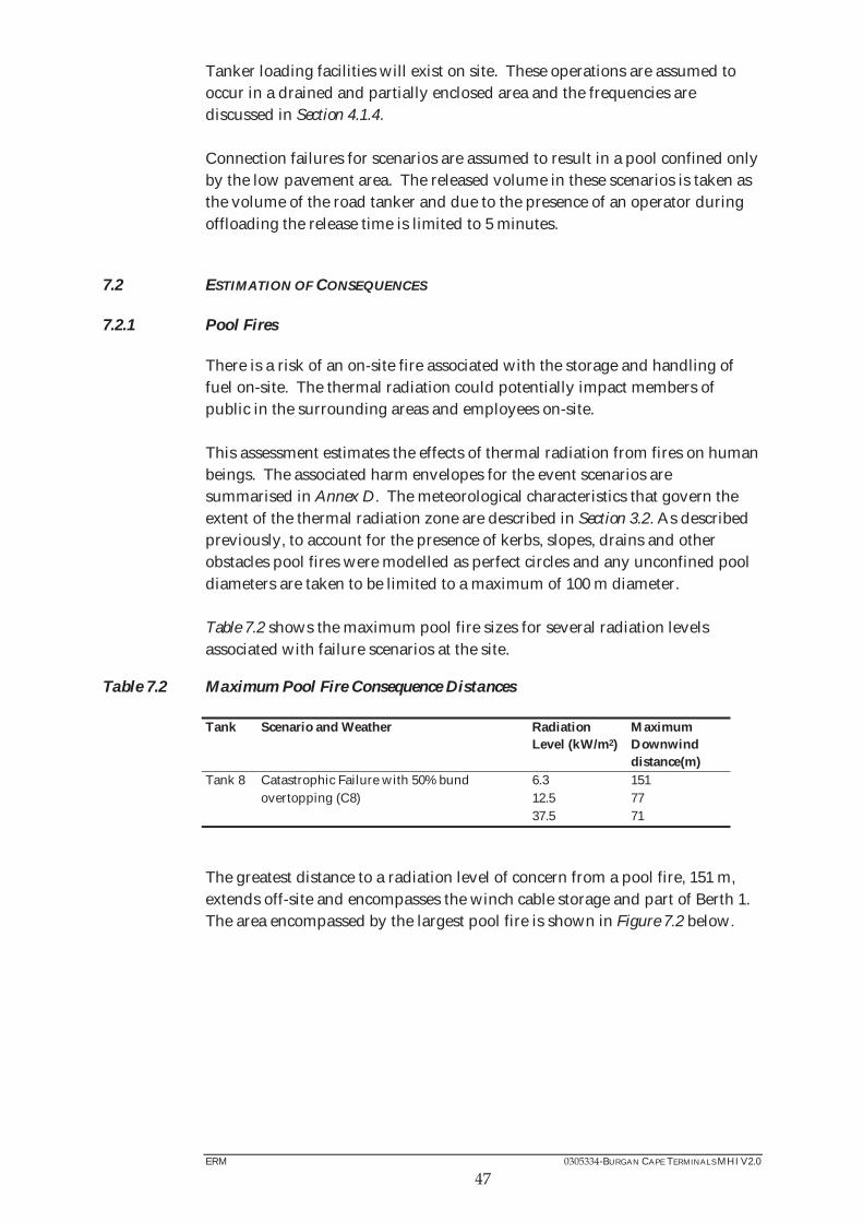
ERM -BURGAN CAPE TERMINALS MHI V2.0
Tanker loading facilities will exist on site. These operations are assumed to occur in a drained and partially enclosed area and the frequencies are discussed in Section 4.1.4. Connection failures for scenarios are assumed to result in a pool confined only by the low pavement area. The released volume in these scenarios is taken as the volume of the road tanker and due to the presence of an operator during offloading the release time is limited to 5 minutes.
7.2 ESTIMATION OF CONSEQUENCES
7.2.1 Pool Fires
There is a risk of an on-site fire associated with the storage and handling of fuel on-site. The thermal radiation could potentially impact members of public in the surrounding areas and employees on-site. This assessment estimates the effects of thermal radiation from fires on human beings. The associated harm envelopes for the event scenarios are summarised in Annex D. The meteorological characteristics that govern the extent of the thermal radiation zone are described in Section 3.2. As described previously, to account for the presence of kerbs, slopes, drains and other obstacles pool fires were modelled as perfect circles and any unconfined pool diameters are taken to be limited to a maximum of 100 m diameter. Table 7.2 shows the maximum pool fire sizes for several radiation levels associated with failure scenarios at the site.
Table 7.2 Maximum Pool Fire Consequence Distances
Tank Scenario and Weather Radiation Level (kW/m2)
Maximum Downwind distance(m)
Tank 8 Catastrophic Failure with 50% bund overtopping (C8)
6.3 151 12.5 77 37.5 71
The greatest distance to a radiation level of concern from a pool fire, 151 m, extends off-site and encompasses the winch cable storage and part of Berth 1. The area encompassed by the largest pool fire is shown in Figure 7.2 below.
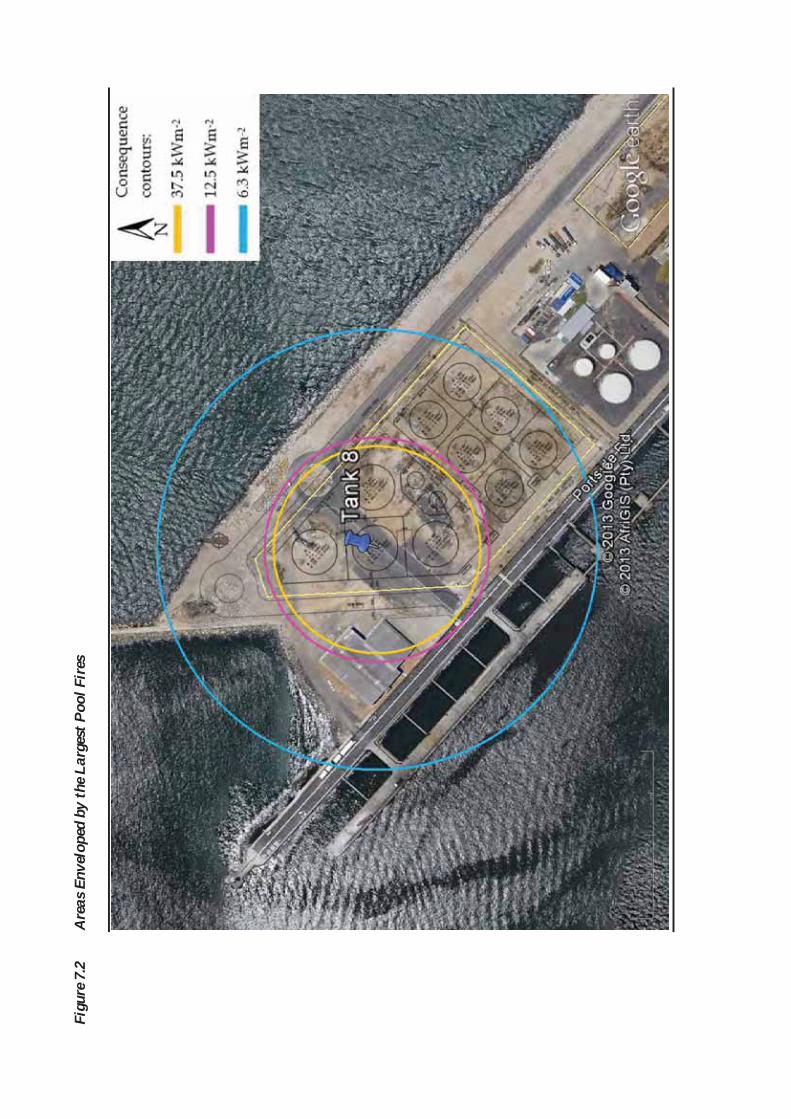
Figu
re 7
.2
Are
as E
nvel
oped
by
the L
arge
st P
ool F
ires

ERM -BURGAN CAPE TERMINALS MHI V2.0
7.2.2 Buncefield Scenarios As was discussed previously, Buncefield-type events are only considered for tanks that are over 5 m in height and are filled at a rate in excess of 0.0278 m3/ s with low flash products (such as Petrol). Taking the above into account, Buncefield scenarios are considered for the tanks listed in Table 7.3.
Table 7.3 Tanks Falling within the Buncefield Criteria
Tank Product Height (m) Maximum Filling Rate (m3/s)
1 Petrol 0.35 3 Petrol 0.35 5 Petrol 0.35
Explosion Overpressure Consequences The peak overpressures observed at Buncefield were extremely high, exceeding two bar (200 kPa) across much of the site. For the purposes of this assessment, the overpressure in Zone B was taken as 250 mbar (25 kPa). Information in the explosion mechanism report (Vol 2 B.11) (1) suggests that there was some degree of building damage up to 2 km from the site. The overpressure at this distance is estimated to be of the order of 10 mbar (1 kPa) (2). For the purposes of this assessment, the harm envelope dimensions that are used for vapour cloud explosions associated with the overfilling of the tanks are the same for each tank and are shown in Table 7.4.
Table 7.4 Distance to Various Overpressures Resulting from a VCE
Overpressure d c S m 2 bar 250 250 -250 0 250 mbar - 0
Large Flash Fire Consequences As discussed previously, for a large flash fire, the dimensions of the flammable vapour cloud formed at Buncefield are used. These dimensions are shown in Table 7.5 below.
Table 7.5 Distance to Flammability Limits Resulting in a Large Flash Fire
Concentration d c S m LFL 135 0 235
(1) Safety and environmental standards for fuel storage sites - Process Safety Leadership Group - Final Report, to be published December 2009 (2) TNO Yellow Book

ERM -BURGAN CAPE TERMINALS MHI V2.0
50
Small Flash Fire Consequences For small flash fires, it is assumed that 20% of the spilled product is vaporised and will disperse. The flammability limits for these clouds are shown in Table 7.6.
Table 7.6 Distance to Flammability Limits Resulting in a Small Flash Fire
Concentration d c S m LFL (Calm weather) 111 121 0 80 0.5LFL (Calm weather) 172 -9 96 LFL (Not calm weather) 18 0 76 0.5LFL (Not calm weather) 220 28 0 107
Results for the Buncefield small flash fire scenario associated with overfilling reveals that facilities up to 305 m from tanks falling within the Buncefield criteria would be impacted. This includes the majority of the surrounding areas of the Winch Cable Storage, FSS, Berth 1, Berth 2 and ships moored at these berths. The detailed results of the consequence modelling are provided in Annex D. The largest distances of a Buncefield incident from Tank 3 are plotted over the site in Figure 7.3. Tanks 1 and 5 would produce similar consequences but centred over the respective tanks.

Figu
re 7
.3
Are
as E
nvel
oped
by
the L
arge
st B
unce
field
Sce
nari
os

ERM -BURGAN CAPE TERMINALS MHI V2.0
52
7.3 ESTIMATION OF INCIDENTS
7.3.1 Pool Fire Frequency Calculations
To determine the probability of a pool fire occurring, the failure rate needs to be modified by the probability of the material finding an ignition source. The probability of a pool fire occurring in the event of a release is therefore equal to the product of the failure rate and the probability of ignition. The frequency of the release scenarios identified in Section 5 is represented in Table 7.7 to Table 7.9. The ignition probability is dependent on a number of factors including the type of site, the release rate and the type of material released.
Table 7.7 Tank Event Frequency Data Utilised in the Risk Analysis (1)
Failure Type – Tanks Frequency
Catastrophic tanks failure 5 x 10⁻⁶ per tank per year Small bund fire 9 x 10⁻⁵ per tank per year Large bund fire 6 x 10⁻⁵ per tank per year
Table 7.8 Failure Frequencies for Road tankers Utilised in the Risk Analysis
Failure Type Frequency Hose failure(2) Full bore x 10-6 per operation 15 mm Hole -6 per operation 5 mm Hole 6 x 10⁻⁶ per operation Road tanker failure(3) Catastrophic failure 1x10⁻⁵ per year Large connection failure 5x10⁻⁷ per year
Table 7.9 Failure Frequencies for Pipework Utilised in the Risk Analysis (4)
Release Hole Size (mm)
Failure Frequency (per metre year) for Pipe Diameter (mm) - -299 300- -
3 1 x 10⁻⁵ 2 x 10⁻⁶ 1 x 10⁻⁶ 8 x 10⁻⁷ 7 x 10⁻⁷
25 5 x 10⁻⁶ 1 x 10⁻⁶ 7 x 10⁻⁷ 5 x 10⁻⁷ -7 1/3 pipe diameter
-7 2 x 10⁻⁷ 1 x 10⁻⁷
Full bore 1 x 10⁻⁶ 5 x 10⁻⁷ 2 x 10⁻⁷ 7 x 10⁻⁸ -8
-6.1 (5) (March 2010).
(1) – 3, March 2010, Section 2 – Summary of Recommended Data (2) Failure Rate and Event Data for use within Land Use Planning Risk Assessments – FR 1.2.3 – Hoses and Couplings (3) Publication Series on Dangerous Substances - Guidelines for quantitative risk assessment, ‘Purple Book’, CPR18E,
Chapter 3.2.9 Transport units in an establishment, Page 3.12 ( ) Failure Rate and Event Data for use within Land Use Planning Risk Assessments – FR 1.3 –Pipework (5) -6.1, March 2010
ERM -BURGAN CAPE TERMINALS MHI V2.0
53
For scenarios considered inside bunds, Scenario 13 - tank Liquid 100m x 100m Bund (Liquid release from onshore tank farm where spill is limited by small or medium sized bund) is used; for releases outside bunded areas Scenario 9 - Large Plant Liquid (Liquid release from Large onshore plant) is used. For low flash point products such as petrol the ignition probabilities are taken as they appear in the OGP report. For higher flash point products such as diesel the report recommends that an additional factor of 0.1 be used to reduce the ignition probability due to the low amount of fuel vapours.
7.3.2 Overfill Frequency Calculations
The frequency of overfilling can be determined by a number of methods, such as fault tree analysis, LOPA assessment etc. The current study used fault tree analysis based upon the proposed overfill protection systems contained in the Burgan Oil Cape Town Terminal Design Operating and Control Philosophy VTTI-0105-0030. The frequency of overfilling is determined by the number of fills multiplied by the probability of failure of the overfill protection systems. These systems include normal operating procedures and tank management as well as high level alarms and Hi-Hi level trips. Boolean algebra is used to determine the likelihood of failure of the overfill protection system. The fault tree used to determine the likelihood of failure of the overfill protection system are shown in Annex F. Fault Tree Frequency Inputs
The number of tank filling operations for the various tanks that meet the Buncefield criteria discussed in Section 6.2.2 affects the frequency of an overfill event. It is understood that all tanks are filled per delivery. The number of tank fills is shown in Section 4.1.2. Fault Tree Probability Inputs
Several common failure frequencies are utilised in the fault tree analysis for personal behaviour as well as equipment failure. The failure rate of mechanical and electrical systems are incorporated and used to define a SIL rating for an element of the overfill protection system. The likelihood of failure on demand of these systems is based on international guidance BS EN 6151 and is shown in Table 7.10.
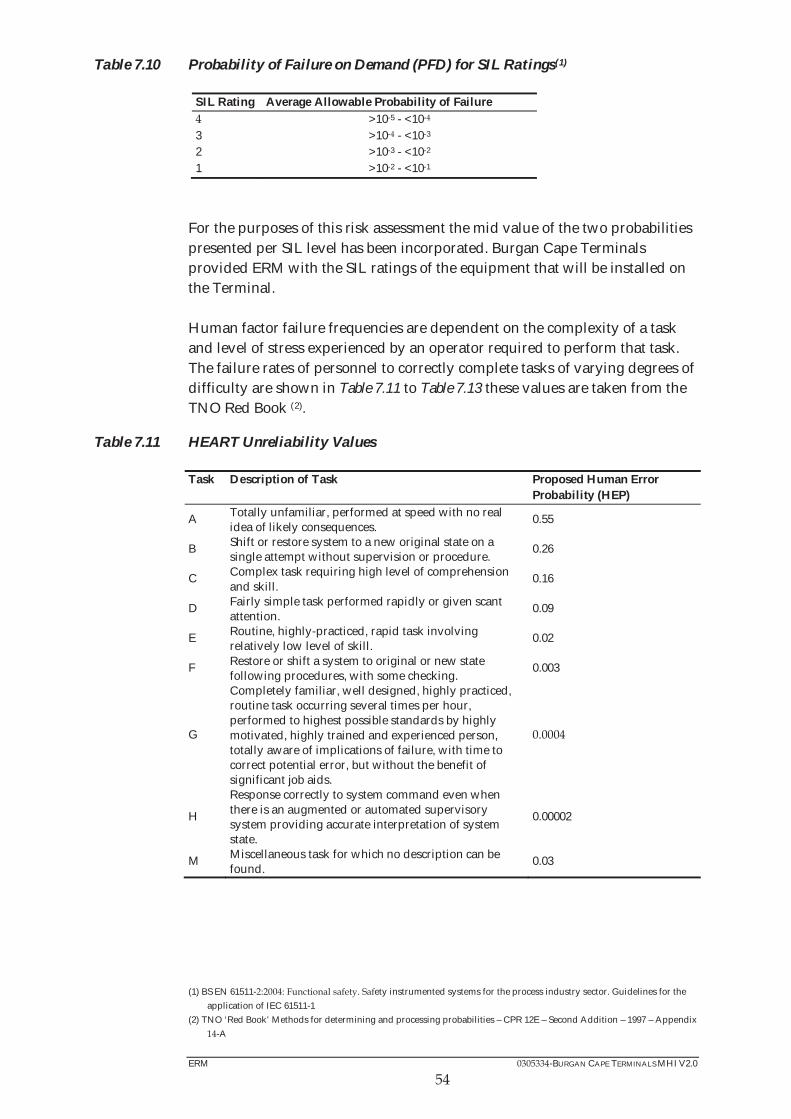
ERM -BURGAN CAPE TERMINALS MHI V2.0
Table 7.10 Probability of Failure on Demand (PFD) for SIL Ratings(1)
SIL Rating Average Allowable Probability of Failure >10-5 - <10-
3 >10- - <10-3 2 >10-3 - <10-2 1 >10-2 - <10-1
For the purposes of this risk assessment the mid value of the two probabilities presented per SIL level has been incorporated. Burgan Cape Terminals provided ERM with the SIL ratings of the equipment that will be installed on the Terminal. Human factor failure frequencies are dependent on the complexity of a task and level of stress experienced by an operator required to perform that task. The failure rates of personnel to correctly complete tasks of varying degrees of difficulty are shown in Table 7.11 to Table 7.13 these values are taken from the TNO Red Book (2).
Table 7.11 HEART Unreliability Values
Task Description of Task Proposed Human Error Probability (HEP)
A Totally unfamiliar, performed at speed with no real idea of likely consequences.
0.55
B Shift or restore system to a new original state on a single attempt without supervision or procedure.
0.26
C Complex task requiring high level of comprehension and skill.
0.16
D Fairly simple task performed rapidly or given scant attention.
0.09
E Routine, highly-practiced, rapid task involving relatively low level of skill.
0.02
F Restore or shift a system to original or new state following procedures, with some checking.
0.003
G
Completely familiar, well designed, highly practiced, routine task occurring several times per hour, performed to highest possible standards by highly motivated, highly trained and experienced person, totally aware of implications of failure, with time to correct potential error, but without the benefit of significant job aids.
H
Response correctly to system command even when there is an augmented or automated supervisory system providing accurate interpretation of system state.
0.00002
M Miscellaneous task for which no description can be found.
0.03
(1) BS EN 61511- ety instrumented systems for the process industry sector. Guidelines for the
application of IEC 61511-1 (2) TNO ‘Red Book’ Methods for determining and processing probabilities – CPR 12E – Second Addition – 1997 – Appendix
-A

ERM -BURGAN CAPE TERMINALS MHI V2.0
55
Table 7.12 Operator Error Estimates (Kletz)
No. Description HEP
1 Omission or incorrect execution of step in a familiar start-up routine
0.001
2 Failure to respond to audible alarm in quiet control room by pressing single button
0.001
3 Failure to respond to auditable alarm in quiet control room by some more complex action such as going outside and selecting correct valve among many
0.01
Failure to respond to audible alarm in busy control room within 10 minutes 0.1
5 Failure to carry out rapid and complex actions to avoid serious incident such as an explosion
0.5
Table 7.13 THERP Estimated HEP's Related to Failure of Administrative Control
No. Description HEP
1 Carry out a plant policy or scheduled tasks such as periodic tests or maintenance performed weekly, monthly, or at longer intervals.
0.01
2 Initiate a scheduled shiftly checking or inspection function.
0.001
3 Use written operations procedures under normal operating conditions.
0.01
Use written operations procedures under abnormal operating conditions.
0.005
5 Use a valve change list or restoration list. 0.01 6 Use written test or calibration procedure. 0.05 7 Use written maintenance procedures. 0.3 8 Use a checklist properly. 0.5
Overfill Prevention Barriers
The overfill prevention barriers considered for the various storage tanks are described in the fault tree in Annex F along with their probability of failure. These are based on current P&IDs, instrumentation SIL ratings for the tanks as well as normal operating procedures as considered by ERM. The resulting overfill probabilities are combined with the filling frequencies to create a frequency of overfilling for each tank which is shown in Table 7.14.
Table 7.14 Overfill Frequency for Tanks with Buncefield Potential
Tanks Base Overfill Frequency
No. Fills per Tank for 6 months
Calculated Overfill Frequency per Tank
6.55 E-07 7 -06 3 6.55 E-07 7 E-06
6.55 E-07 7 -06
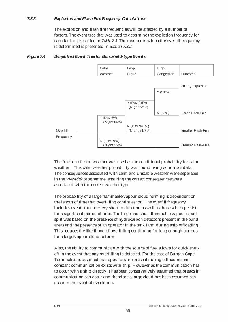
ERM -BURGAN CAPE TERMINALS MHI V2.0
56
7.3.3 Explosion and Flash Fire Frequency Calculations
The explosion and flash fire frequencies will be affected by a number of factors. The event tree that was used to determine the explosion frequency for each tank is presented in Table 7.4. The manner in which the overfill frequency is determined is presented in Section 7.3.2.
Figure 7.4 Simplified Event Tree for Buncefield-type Events
Calm Large High Weather Cloud Congestion Outcome
Strong Explosion
Y (50%)
Y (Day 0.5%) (Night 5.5%)
N (50%) Large Flash-Fire
Y (Day 6%) %)
Overfill N (Day 99.5%) (Night ) Smaller Flash-Fire
Frequency
N %) (Night 36%) Smaller Flash-Fire
The fraction of calm weather was used as the conditional probability for calm weather. This calm weather probability was found using wind-rose data. The consequences associated with calm and unstable weather were separated in the ViewRisk programme, ensuring the correct consequences were associated with the correct weather type. The probability of a large flammable vapour cloud forming is dependent on the length of time that overfilling continues for. The overfill frequency includes events that are very short in duration as well as those which persist for a significant period of time. The large and small flammable vapour cloud split was based on the presence of hydrocarbon detectors present in the bund areas and the presence of an operator in the tank farm during ship offloading. This reduces the likelihood of overfilling continuing for long enough periods for a large vapour cloud to form. Also, the ability to communicate with the source of fuel allows for quick shut-off in the event that any overfilling is detected. For the case of Burgan Cape Terminals it is assumed that operators are present during offloading and constant communication exists with ship. However as the communication has to occur with a ship directly it has been conservatively assumed that breaks in communication can occur and therefore a large cloud has been assumed can occur in the event of overfilling.
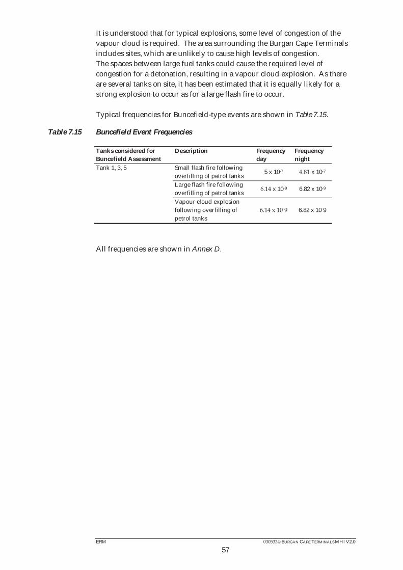
ERM -BURGAN CAPE TERMINALS MHI V2.0
57
It is understood that for typical explosions, some level of congestion of the vapour cloud is required. The area surrounding the Burgan Cape Terminals includes sites, which are unlikely to cause high levels of congestion. The spaces between large fuel tanks could cause the required level of congestion for a detonation, resulting in a vapour cloud explosion. As there are several tanks on site, it has been estimated that it is equally likely for a strong explosion to occur as for a large flash fire to occur. Typical frequencies for Buncefield-type events are shown in Table 7.15.
Table 7.15 Buncefield Event Frequencies
Tanks considered for Buncefield Assessment
Description Frequency day
Frequency night
Tank 1, 3, 5 Small flash fire following overfilling of petrol tanks
5 x 10-7 x 10-7
Large flash fire following overfilling of petrol tanks
x 10-9 6.82 x 10⁻⁹
Vapour cloud explosion following overfilling of petrol tanks
6.82 x 10 9
All frequencies are shown in Annex D.

ERM -BURGAN CAPE TERMINALS MHI V2.0
58
8 RISK ANALYSIS RESULTS
8.1 FATALITY RISK CALCULATION
The scenario frequencies and consequence results are used within the ERM ViewRisk risk summation package to calculate the individual risk and societal risk associated with the bulk fuel installations.
8.1.1 Location Specific Individual Risk for the site
Individual risks are by definition specific to individuals and need to take into account the extent and circumstances under which exposure arises. For instance, the risk will depend on the amount of time the individual spends outdoors as well as the time they may spend indoors which will afford them some protection. Risks are calculated for hypothetical persons located both indoors and outdoors. The percentage of time spent by people outdoors and indoors is discussed in Section 4.5. The risk contours presented in this section represent Location Specific Individual Risk (LSIR). It should be noted that the Location Specific
hours a day 365 days a year. This is therefore an overestimate of the individual risk to personnel or public who may be present at these locations. Individual risk of fatality contours for persons located outdoors and indoors at 1 x 10⁻⁶, 1 x 10⁻⁵, 1 x 10- and 1 x 10⁻³ (1, 10, 100 and 1,000 chances per million per year (cpm)) for the installations were calculated using the fatality probabilities detailed in Section 6.2.4. Location Specific Individual Risks – Including Buncefield Scenarios
Figure 8.1 represents the location specific individual risks (LSIR) for hypothetical persons located outdoors. It can be seen that the 1 x 10⁻⁶, (1 cpm) contour extends off site to the north over the mole and harbour water. The winch cable storage is encompassed to the west, with Berth 1, 2 and the FFS Refineries storage encompassed to the south. Beyond the 1 x 10⁻⁶ (1 cpm) contour risks are broadly acceptable. Between the 1 x 10⁻⁶ (1 cpm) contour and the 1 x 10⁻⁵ (10 cpm) contour, the risks to the public are considered tolerable, so long as they can be demonstrated by Burgan Cape Terminals to be as low as reasonably practicable (ALARP). The 1 x 10⁻⁵ (10 cpm) contour extends off site following the site boundary, some area of the winch cable storage is enveloped to the west as well as the FFS Refineries storage to the south east.

ERM -BURGAN CAPE TERMINALS MHI V2.0
59
The 1 x 10- (100 cpm) contour extends off site to a maximum of 10 m but does not envelope any of the surrounding sites. The risk to the workers in the adjacent facilities does not exceed 1 x 10- (100 cpm). Therefore the risks are not considered intolerable according to the assessment criteria of Section 6.3.3. There is no 1 x 10⁻³ (1,000 cpm) contour. Figure 8.2 represents the LSIR for persons located indoors. It can be seen that the 1 x 10⁻⁶ (1 cpm) contour extends off site to the north over the mole and harbour water. The winch cable storage is encompassed to the west, with Berth 1, 2 and the FFS Refineries storage encompassed to the south. Beyond the 1 x 10⁻⁶ (1 cpm) contour risks are broadly acceptable. Between the 1 x 10⁻⁶ (1 cpm) contour and the 1 x 10⁻⁵ (10 cpm) contour, the risks to the public are considered tolerable, so long as they can be demonstrated by Burgan Cape Terminals to be as low as reasonably practicable (ALARP). The 1 x 10⁻⁵ (10 cpm) contour extends off site following the site boundary, some area of the winch cable storage is enveloped to the west as well as part of the FFS Refineries storage to the south east. The 1 x 10- (100 cpm) contour extends off site to a maximum of 10 m but does not envelope any of the surrounding sites. There is no 1 x 10⁻³ (1000 cpm) contour. The risk to the workers in the adjacent facilities does not exceed 1 x 10- (100 cpm). Therefore the risks are not considered intolerable according to the assessment criteria of Section 6.3.3.

Figu
re 8
.1
Loca
tion
Spe
cific
Indi
vidu
al R
isks
of F
atal
ity
Cont
ours
for P
erso
ns L
ocat
ed O
utdo
ors
– In
clud
ing
Bunc
efie
ld S
cena
rios

Figu
re 8
.2
Loca
tion
Spe
cific
Indi
vidu
al R
isks
of F
atal
ity
Cont
ours
for P
erso
ns L
ocat
ed In
door
s - I
nclu
ding
Bun
cefie
ld S
cena
rios

ERM -BURGAN CAPE TERMINALS MHI V2.0
62
Location Specific Individual Risks – Excluding Buncefield Scenarios
There is not a significant difference in the size and shape of the LSIR contours when the Buncefield scenarios are removed. This is due to the implementation of Buncefield recommendations that reduces the likelihood of Buncefield type scenarios at the Burgan Cape Terminals site.
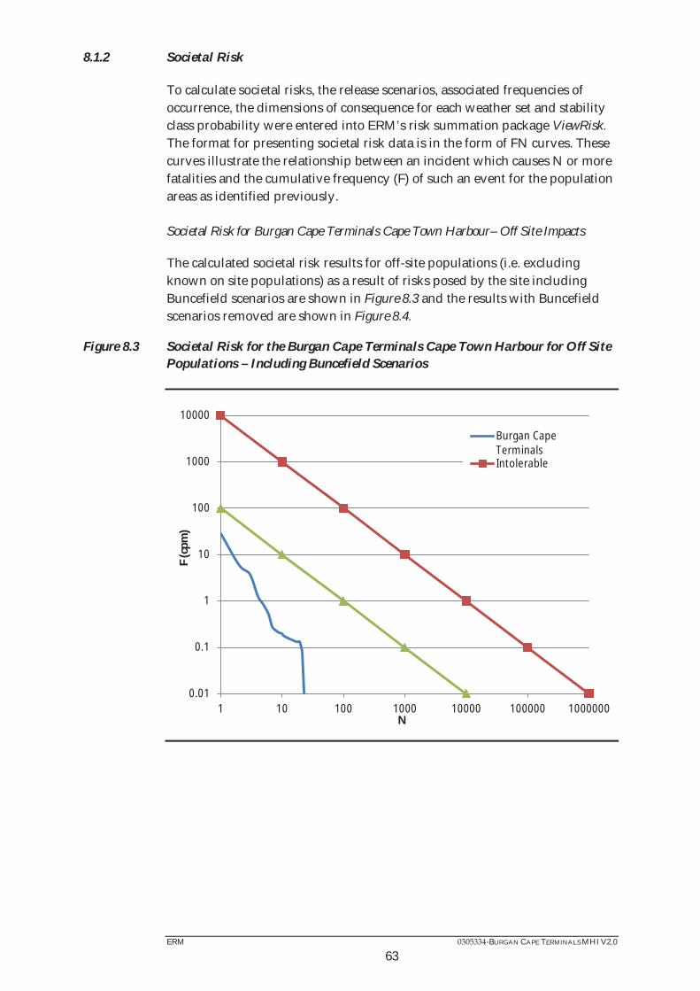
ERM -BURGAN CAPE TERMINALS MHI V2.0
63
8.1.2 Societal Risk
To calculate societal risks, the release scenarios, associated frequencies of occurrence, the dimensions of consequence for each weather set and stability class probability were entered into ERM’s risk summation package ViewRisk. The format for presenting societal risk data is in the form of FN curves. These curves illustrate the relationship between an incident which causes N or more fatalities and the cumulative frequency (F) of such an event for the population areas as identified previously. Societal Risk for Burgan Cape Terminals Cape Town Harbour– Off Site Impacts
The calculated societal risk results for off-site populations (i.e. excluding known on site populations) as a result of risks posed by the site including Buncefield scenarios are shown in Figure 8.3 and the results with Buncefield scenarios removed are shown in Figure 8.4.
Figure 8.3 Societal Risk for the Burgan Cape Terminals Cape Town Harbour for Off Site Populations – Including Buncefield Scenarios
0.01
0.1
1
10
100
1000
10000
1 10 100 1000 10000 100000 1000000
F (c
pm)
N
Burgan CapeTerminalsIntolerable

ERM -BURGAN CAPE TERMINALS MHI V2.0
Figure 8.4 Societal Risk for the Burgan Cape Terminals Cape Town Harbour for Off Site Populations – Excluding Buncefield Scenarios
As illustrated by Figure 8.3 and Figure 8.4, the total societal risk F-N curve lies below the ‘Broadly Acceptable’ indicator line and therefore below the ‘Intolerable’ indicator line as defined in the societal risk criteria in Section 6.3.3. Therefore, the risks are considered broadly acceptable but Burgan Cape Terminals should reduce risk levels to As Low As Reasonably Possible (ALARP).
0.01
0.1
1
10
100
1000
10000
1 10 100 1000 10000 100000 1000000
F (c
pm)
N
Burgan CapeTerminalsIntolerable

ERM -BURGAN CAPE TERMINALS MHI V2.0
65
8.1.3 Rate of Harm (Contributors to the Risk)
The Rate of Harm (also known as the Potential Loss of Life, PLL, or Expectation Value, EV) is the sum of the number of people harmed multiplied by the frequency with which this happens. The Rate of Harm breakdown indicates those scenarios which are the largest contributors to the risk. The Rate of Harm breakdown for the site is presented in Table 8.1.
Table 8.1 Rates of Harm Contributing Greater than 1% - Including Buncefield Scenarios
Location Description Rate of Harm (people*cpm)
Rate of Harm (%)
Trans to Gantry Petrol pool fire 9.6 20.6 Diesel pool fire 20.3
Trans to Gantry Petrol pool fire 10.3 A6 Diesel pool fire 3.3 7.1 A2 Diesel pool fire 1.9 B2 Diesel pool fire 1.9 Buncefield A5 SFF F2 1.2 2.7 Trans to Gantry Diesel pool fire 1.1 2.3 Buncefield A3 SFF F2 1.1 2.3 Buncefield A5 VCE 1.0 2.2 Buncefield A3 SFF B3 C8 1.0 2.1 Buncefield A3 VCE 1.0 2.1
Diesel pool fire 0.9 2.0 Buncefield A1 VCE 0.9 2.0 Buncefield A5 SFF B3 C8 0.9 1.9 Buncefield A1 SFF F2 0.8 1.8 Ship transfer Petrol pool fire 0.8 1.8 Buncefield A1 SFF B3 C8 0.7 1.6 A3 Petrol pool fire 0.7 1.6 Trans to Gantry Diesel pool fire 0.5 1.2 Other 1.51
Total 46.4
The Rate of Harm breakdown indicates that 9.5% of the RoH table is made up of vapour cloud explosions and small flash fires which are due to Buncefield-type scenarios. Buncefield scenarios usually contribute the highest values on the ROH table. However, due to the implementation of Buncefield recommendations such as independent high high trips closing incoming flow valves the impact of Buncefield scenarios has been reduced and pool fires are the main contributors to Burgan Cape terminals ROH. Removing the Buncefield scenarios show which other events contribute to the risk of the site. The rates of harm for these events are shown in Table 8.2.

ERM -BURGAN CAPE TERMINALS MHI V2.0
66
Table 8.2 Rates of Harm Contributing Greater than 1% - Excluding Buncefield Scenarios
Location Description Rate of Harm (people*cpm)
Rate of Harm (%)
Trans to Gantry Petrol pool fire 9.55 25.56 Diesel pool fire 25.15
Trans to Gantry Petrol pool fire 12.79 A6 Diesel pool fire 3.31 8.86 A2 Diesel pool fire 1.92 B2 Diesel pool fire 1.92 Trans to Gantry Diesel pool fire 1.07 2.87
Diesel pool fire 2.51 Ship transfer Petrol pool fire 0.85 2.26 A3 Petrol pool fire 0.72 1.93 Trans to Gantry Diesel pool fire A6 Diesel pool fire 1.13 Ship transfer Petrol pool fire 1.13 Other Total 37.37
As indicated in Table 8.2, without Buncefield scenarios, the largest risks are still associated with the transfer of fuel from the ship and to the gantry via pipework.
8.2 ESCALATION EFFECTS
No escalation effects (i.e. a minor incident escalating to a major incident) are considered in this risk assessment. It is judged that escalation impacts (in terms of the immediate effect on people off-site) associated with large, multi-tank pool fires are unlikely to result in more severe consequences than the original fire. This is due to the fact that the majority of the bulk storage tanks are contained within intermediate bunds in the primary bund, thereby limiting the effects of the pool fire. Furthermore, it is expected that evacuation of personnel would take place when the initial pool fire occurred. In the event of a vapour cloud explosion, the effects of the explosion could impact adjacent tanks, resulting in secondary effects such as a large unconfined pool fire or multi-tank bund fires (as observed at Buncefield). However, the majority of the casualties would be expected to come from the vapour cloud explosion itself.

ERM -BURGAN CAPE TERMINALS MHI V2.0
67
8.3 LUP RISK CALCULATION
The scenario frequencies and consequence results are used within the ERM ViewRisk risk summation package to calculate the individual risk associated with bulk fuel installations. Individual risk contour lines at 1 x 10⁻⁵, 1 x 10⁻⁶ and 3 x 10⁻⁷ (10, 1 and 0.3 chances per million per year (cpm)) of receiving a dangerous dose or worse from the flammable liquid installations were calculated and illustrated on a map of the site. The 1 x 10⁻⁵, 1 x 10⁻⁶ and 3 x 10⁻⁷ (10, 1 and 0.3 chances per million per year (cpm))values are the risk levels used by the UK HSE to set the three zone land-use planning policy (refer to Section 6.3.1). Figure 8.5 illustrates the risk contour lines for the proposed Burgan Cape Terminals site. The individual risk contours can be compared with the risk criteria used by the UK Health and Safety Executive (HSE) for deciding upon the risk and hence, acceptability of developments around MHIs. The criteria are listed in Table 6.10 of Section 6.3.1. As shown in Figure 8.5, the risk consultation distance i.e. the 3 x 10⁻⁷ (0.3 cpm) contour measured from the site boundary extends off-site to the west partly enveloping the winch cable store and to the south east of the storage area enveloping the FFS Refineries site as well as over the edge of the mole to the north. The middle zone 1 x 10⁻⁶ (1 cpm) contour follows the same trend as the 3 x 10⁻⁷ (0.3 cpm) contour to the north and partly extends over the FFS Refineries site and Berth 2. The 1 x 10⁻⁵ (10 cpm) inner zone contour extends off site and follows similar trend to the 1 x 10⁻⁶ (1 cpm) contour but a reduced amount towards the north and the area surrounding the road loading gantry. Using the criteria outlined in section 6.3.1 it has been shown that the Burgan Cape Terminals site falls within the ‘Don’t Advise Against DAA’ category for all 3 probability of dangerous dose zones. This is because the contours only extend onto land that is used for ‘The normal working public’ and not sensitive developments such as hospitals or schools. As a result, for the current land-use surrounding the site, the storage and use of flammable liquids within the site is acceptable in accordance with the HSE land-use planning assessment. However, restrictions on future development around the site should be enforced based on the LUP criteria outlined in section 6.3.1. Risk contours shown in Figure 8.5 should be compared against the criteria in section 6.3.1 to deem if any proposed future development falls into the ‘Advise Against AA’ or ‘Don’t Advise Against DAA’ category. If the development falls within the ‘Advise Against AA’ category the proposed development cannot be continued.
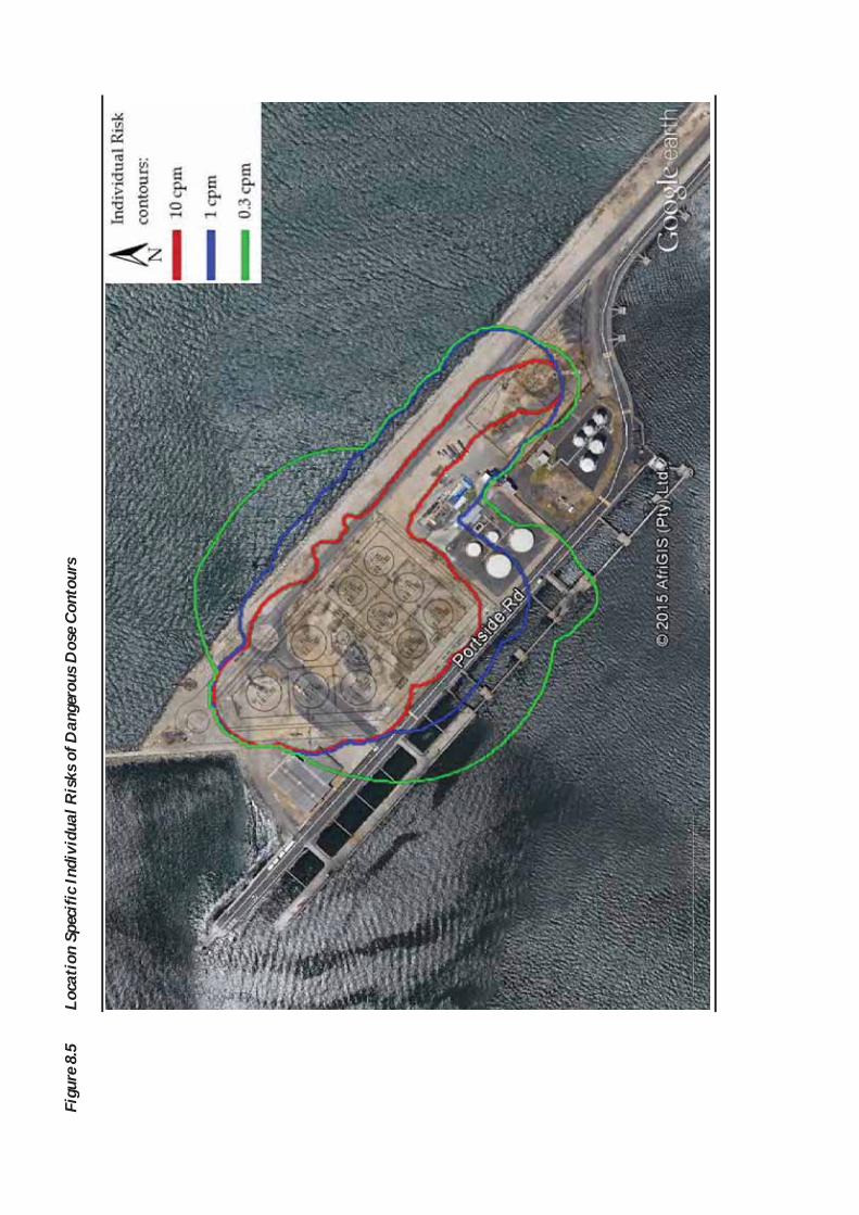
Figu
re 8
.5
Loca
tion
Spe
cific
Indi
vidu
al R
isks
of D
ange
rous
Dos
e Co
ntou
rs

ERM -BURGAN CAPE TERMINALS MHI V2.0
69
9 NEIGHBOURING MAJOR HAZARDOUS INSTALLATIONS
There is only one neighbouring Major Hazardous Installation known to ERM as described in Section 3 which is the FFS Refineries (Pty) Ltd site. From the risk profiles shown in Section 8, the neighbouring FFS Refineries MHI site will be partly enveloped by the 1 x 10⁻⁶ (1 cpm) and 1 x 10⁻⁵ (10 cpm) contours. The main contributor of the risks to which the surrounding MHI’s are exposed is flash fires and explosions from a Buncefield-type incident.

ERM -BURGAN CAPE TERMINALS MHI V2.0
70
10 EMERGENCY PLANNING
The current Burgan Cape Terminals, Cape Town Harbour site Emergency Response Plan (ERP), which was revised during October 2011, and which is required to be included within the MHI assessment, is shown in Annex E. Although the existing ERP has been compiled to deal with a number of potential incidents which could occur on-site, this plan will have to be reviewed and where necessary revised to take into account of the findings of this risk assessment and must comply with the regulations as outlined in Section 10.1. The potential consequences of the incidents identified in this assessment should be discussed with the local Emergency Services, Transnet Port Authorities and the Burgan Cape Terminals personnel, with the ERP being revised as a result of the discussions where necessary. It is recommended that the ERP is maintained and tested regularly. The Local Emergency Services, Transnet Port Authorities and the adjacent industries should also be kept informed of Burgan Cape Terminal’s emergency plans, and included in future trial emergency drills.
10.1 MHI REGULATIONS, SECTION 6 - ON SITE EMERGENCY PLAN
Section 6 of The Major Hazard Installation Regulations; outline the requirements for on-site emergency planning. All of these points must be complied with by Burgan Cape Terminals within the ERP. “6.(1) An employer, self-employed person and user shall after submission of the information contemplated in regulation 3 (4) –
a) establish an on-site emergency plan to be followed inside the premises of the installation or part of the installation classified as a major hazard installation in consultation with the relevant health and safety representative or the relevant health and safety committee;
b) discuss the emergency plan with the relevant local government, taking into
consideration any comment on the risk related to the health and safety of the public;
c) review the on-site emergency plan and where necessary, update the plan, in
consultation with the relevant local government service at least once every three years;
d) sign a copy of the on-site emergency plan in the presence of two witnesses, who
shall attest the signature;
e) ensure that the on-site emergency plan is readily available at all times for implementation and use;

ERM -BURGAN CAPE TERMINALS MHI V2.0
71
f) ensure that all employees are conversant with the on-site emergency plan; and
g) cause the on-site emergency plan to be tested in practice at least once a year and
keep a record of such a test.”
ERM -BURGAN CAPE TERMINALS MHI V2.0
72
11 CONCLUSIONS
The individual risks of fatality have been calculated for the Burgan Cape Terminals, Cape Town Harbour site. The study has shown that the operations have the potential to adversely affect the health and safety of people working on-site as well as members of the public off-site and other workers on other sites in the area. The consequence of a pool fire from a catastrophic release from a tank on-site can extend up to 151 m and poses a threat to workers on-site and people off-site. The individual and the societal risk have been shown to be tolerable for members of the public if it can be demonstrated that Burgan Cape Terminals has taken measures to ensure the levels of risk are As Low As Reasonably Practicable (ALARP) for members of the public. For workers on-site and other sites in close proximity to Burgan Cape Terminals site, the individual risks are found to be below 1 x 10⁻³ (1000 cpm) and therefore tolerable if Burgan Cape Terminals can demonstrate that they are ALARP. As noted in Section 8, a large portion of the risk to the surrounding areas is as a result of Buncefield type scenarios. The risk of having a Buncefield-type incident can be reduced by means of Burgan Cape Terminals investigating ways of reducing the risk of overfilling Petrol tanks on site and including these into the final site design. Using the criteria outlined in Section 6.3 it has been shown that the Burgan Cape Terminals Cape Town Harbour site falls within the ‘Don’t Advise Against DAA’ category for all 3 probability of dangerous dose zones. As a result, for the current land-use surrounding the Eastern Mole site, the storage and use of flammable liquids within the site is acceptable in accordance with the HSE land-use planning assessment. Environmental Resources Management Southern Africa (Pty) Ltd would declare the proposed design of the Burgan Cape Terminals site located at Portside Road, Eastern Mole Berth, Western Cape (GPS coordinates in decimal degrees: :
) a Major Hazard Installation (MHI) as outlined in the current legislation. As a result of being declared a MHI, the Requirements of the MHI Regulations must be followed completely to ensure the Burgan Cape Terminals is legally compliant. Copies of this risk assessment must be submitted to the Local Provincial Director of the Department of Labour, the Chief Inspector of the Department of Labour Head Office in Pretoria and the Local Authorities.


Annex B
Major Hazard Installation Legislation

Government Gazette
REPUBLIC OF SOUTH AFRICA
Regulation Gazette No. 7122 Vol. 433 Pretoria 30 July 2001 No. 22506
Government Gazette 30 July 2001
GOVERNMENT NOTICE
DEPARTMENT OF LABOUR No. R. 692 30 July 2001
OCCUPATIONAL HEALTH AND SAFETY ACT, 1993
MAJOR HAZARD INSTALLATION REGULATIONS The Minister of Labour has, after consultation with the Advisory Council for Occupational Health and Safety, under section 43 of the Occupational Health and Safety Act (Act No. 85 of 1993), made the regulations in the Schedule.

Government Gazette 30 July 2001
ERM 0305334-BURGAN CAPE TERMINALS MHI V1.0
B4
SCHEDULE
1 DEFINITIONS
In these regulations any expression to which a meaning has been assigned in the Act shall have the meaning so assigned and, unless the context otherwise indicates – “emergency plan” means a plan in writing which, on the basis of identified potential incidents at the installation, together with their consequences, describes how such incidents and their consequences should be dealt with on-site and off-site; “local government” means a local government as defined in section 1 of the Local Government Transition Act, 1993 (Act No. 209 of 1993); “material safety data sheet” means a material safety data sheet as contemplated in regulation 7 of the General Administrative Regulation; “near miss” means any unforeseen event involving one or more hazardous substances which, but for mitigating effects, actions or systems, could have escalated to a major incident; “on site emergency plan” means the emergency plan contemplated in regulation 6; “risk assessment” means the process contemplated in regulation 5; “rolling stock” means any locomotive, coach, railway carriage, truck, wagon or similar contrivance used for the purpose of transporting persons, goods or any other thing, and which can run on a railway; “temporary installation” means an installation that can travel independently between planned points of departure and arrival for the purpose of transporting any substance, and which is only deemed to be an installation at the points of departure and arrival respectively; “the Act” means the Occupational Health and Safety Act, 1993 (Act No. 85 of 1993); “transit” includes any time or place in which rolling stock may be between planned points of departure and arrival.

Government Gazette 30 July 2001
ERM 0305334-BURGAN CAPE TERMINALS MHI V1.0
B5
2 SCOPE OF APPLICATION
(1) Subject to the provisions of sub-regulation (3) these regulations shall apply to employers, self-employed persons and users, who have on their premises, either permanently or temporarily, a major hazard installation or a quantity of a substance which may pose a risk, that could affect the health and safety of employees and the public.
(2) These regulations shall be applicable to local governments, with specific reference to regulation 9.
(3) These regulations shall not apply to nuclear installations registered in terms of the Nuclear Energy Act, 1993 (Act No. 131 of 1993).
3 NOTIFICATION OF INSTALLATION
(1) Every employer, self-employed person and user, shall notify the chief inspector, provincial director and relevant local government in writing of-
(a) the erection of any installation which will be a major hazard installation, prior to commencement of erection thereof, and;
(b) the conversion of any existing installation into a major hazard installation prior to such conversion.
(2) Every employer, self-employed person user shall notify the chief inspector, the local government and the provincial director within 60 days of the promulgation of these regulations of an existing major hazard installation.
(3) No employer, self-employed person and user shall modify an installation by increasing its storage or production capacity or altering the process or by affecting any other change that may increase the risk of an existing major hazard installation, without first notifying the chief inspector, the relevant local government and provincial director in writing.
(4) The information submitted by and required from an employer, self-employed person and user in terms of sub-regulations (1), (2), and (3) shall include -
(a) the physical address of the installation;
(b) the complete material safety data sheets of all substances that resulted in the installation being classified as a major hazard installation;

Government Gazette 30 July 2001
ERM 0305334-BURGAN CAPE TERMINALS MHI V1.0
B6
(c) the envisaged maximum quantity of such substance that may be on the premises at any one time;
(d) the risk assessment of the major hazard installation as contemplated in regulation 5 (1); and
(e) any further information that may be deemed necessary by an inspector in the interests of health and safety of the public.
(5) Sub-regulations (1), (2) and (3) shall not apply to railway rolling stock in transit.
(6) An employer, self-employed person and user shall advertise the notifications contemplated in sub-regulations (1), (2) and (3) in at least one newspaper serving the communities in the vicinity of the installation which is to be declared a major hazard installation, a proposed major hazard installation or an existing installation which is to be modified, and by way of notices posted within those communities.
4 TEMPORARY INSTALLATIONS
(1) Any employer, self-employed person and user who has a temporary installation on his or her premises which would, taking into consideration the risks attached to the quantity of substance and the procedure of discharge, result in that temporary installation being declared a major hazard installation if it were not a temporary installation, shall be deemed to be responsible for the storage and discharge of that installation while on his or her premises.
(2) An employer, self-employed person and user contemplated in sub-regulation (1) shall ensure that a risk assessment for the storage and discharge procedure be carried out for a temporary installation prior to the risk coming into existence.
(3) An employer, self-employed person and user contemplated in sub-regulation (1) shall, after taking into consideration the risk assessment, take reasonably practicable steps that may be necessary to reduce the risks attached to the storage and discharge of such temporary installation.

Government Gazette 30 July 2001
ERM 0305334-BURGAN CAPE TERMINALS MHI V1.0
B7
5 RISK ASSESSMENT
(1) An employer, self-employed person and user shall, after consultation with the relevant health and safety representative or relevant health and safety committee, carry out a risk assessment at intervals not exceeding five years and submit such risk assessment to the chief inspector, relevant local government and provincial director.
(2) The risk assessment is the process of collecting, organising, analysing, interpreting, communicating and implementing information in order to identify the probable frequency, magnitude and nature of any major incident which could occur at a major hazard installation, and the measures required to remove, reduce or control the potential causes of such an incident.
(3) An employer, self-employed person and user shall, after informing the relevant health and safety representative or relevant health and safety committee in writing of the arrangements made for the assessment contemplated in sub-regulation (1), give them 60 days within which to comment thereon and ensure that the results of the assessment are made available to the relevant representative or committee who may comment thereon.
(4) An employer, self-employed person and user shall make available on the premises a copy of the latest risk assessment for inspection by an inspector.
(5) An employer, self-employed person and user shall ensure that the risk assessment as contemplated in sub-regulation (1) shall -
(a) be carried out by an Approved Inspection Authority which is competent to express an opinion as to the risks associated with the major hazard installation; and
(b) at least include –
(i) a general process description of the major hazard installation;
(ii) a description of the major incidents associated with this type of installation and the consequences of such incidents, which shall include potential incidents;
(iii) an estimation of the probability of a major accident;
(iv) a copy of the on site emergency plan;
(v) an estimation of the total result in the case of an explosion or fire;

Government Gazette 30 July 2001
ERM 0305334-BURGAN CAPE TERMINALS MHI V1.0
B8
(vi) in the case of toxic release, an estimation of concentration effects of such release;
(vii) the potential effect of an incident on a major hazard installation or part thereof on an adjacent major hazard installation or part thereof;
(viii) the potential effect of a major incident on any other installation, members of the public and residential areas;
(ix) metrological tendencies;
(x) the suitability of existing emergency procedures, for the risks identified;
(xi) any requirements as laid down in terms of the Environment Conservation Act, 1989 (Act No. 73 of 1989); and
(xii) any organisational measures that may be required.
(6) (a) An employer, self-employed person and user shall ensure that the risk assessment required in terms of sub-regulation (1) is reviewed forthwith if –
(i) there is a reason to suspect that the preceding assessment is no longer valid;
(ii) there has been a change in the process involving a substance resulting in the installation being classified a major hazard installation or in the methods, equipment or procedures in the use, handling or processing of that substance; or
(iii) after an incident that has brought the emergency plan into operation or after any near miss.
(b) Where the risk assessment has been updated an employer, self-employed person and user shall submit a copy of the updated risk assessment to the chief inspector, the relevant local government and the provincial director within sixty (60) days.
(7) Sub-regulation (5) (b) shall not apply in the case of rolling stock in transit: Provided that the operator of a railway shall ensure -
(a) that a risk assessment applicable to rolling stock in transit is carried out and made available for inspection at the request of an inspector or local government or both that local government and inspector, as the case may be; and

Government Gazette 30 July 2001
ERM 0305334-BURGAN CAPE TERMINALS MHI V1.0
B9
(b) that in the interest of health and safety of the public the necessary precautions are taken.
(8) An employer, self-employed person and user shall ensure that risk assessments contemplated in sub-regulations (1) and (5) (a) be made available for scrutiny by any interested person or any person that may be affected by the activities of a major hazard installation, at a time, place and in a manner agreed upon between the parties.
6 ON-SITE EMERGENCY PLAN
(1) An employer, self-employed person and user shall after submission of the information contemplated in regulation 3 (4) –
(a) establish an on site emergency plan to be followed inside the premises of the installation or part of the installation classified as a major hazard installation in consultation with the relevant health and safety representative or the relevant health and safety committee;
(b) discuss the emergency plan with the relevant local government, taking into consideration any comment on the risk related to the health and safety of the public;
(c) review the on-site emergency plan and where necessary, update the plan, in consultation with the relevant local government service at least once every three years;
(d) sign a copy of the on-site emergency plan in the presence of two witnesses, who shall attest the signature;
(e) ensure that the on-site emergency plan is readily available at all times for implementation and use;
(f) ensure that all employees are conversant with the on-site emergency plan; and
(g) cause the on-site emergency plan to be tested in practice at least once a year and keep a record of such a test.
(2) An employer, self-employed person and user owning or in control of a pipeline that could pose a threat to the general public shall inform the relevant local government and shall be jointly responsible with the relevant government for the establishment and implementation of an on-site emergency plan.

Government Gazette 30 July 2001
ERM 0305334-BURGAN CAPE TERMINALS MHI V1.0
B10
(3) Sub-regulation (1) shall not apply to rolling stock in transit: Provided that the operator of a railway shall -
(a) establish an emergency plan for each route traversed within twelve (12) months of the coming into operation of these regulations;
(b) draw up the plan as contemplated in paragraph (a) in consultation with the local government through whose jurisdiction the rolling stock is being transported;
(c) sign a copy of the on-site emergency plan in the presence of two witnesses, who shall attest the signature;
(d) ensure that the plan is readily available at all times for implementation and use; and
(e) cause that plan to be tested when reasonably practicable and keep a record of such a test.
7 REPORTING OF RISK AND EMERGENCY OCCURRENCES
(1) Every employer, self-employed person and user of a major hazard installation and owner or user of a pipeline shall –
(a) Subject to the provisions of regulation 6 of the General Administrative Regulations, within 48 hours by means of telephone, facsimile or similar means of communication inform the chief inspector, the provisional director and relevant local government of the occurrence of a major incident or an incident that brought the emergency plan into operation or any near miss;
(b) submit a report in writing to the chief inspector, provincial director and local government within seven days; and
(c) investigate and record all near misses in a register kept on the premises, which shall at all times be available for inspection by an inspector and the local government.
(2) Every employer, self-employed person and user shall in the case of a major incident or an incident contemplated in sub-regulation (1) that was or may have been caused by a substance, inform the supplier of that substance of the incident.
(3) An employer, self-employed person and user shall -
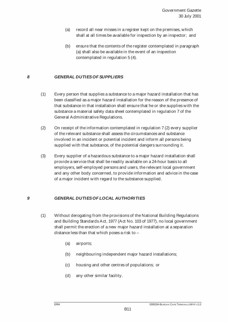
Government Gazette 30 July 2001
ERM 0305334-BURGAN CAPE TERMINALS MHI V1.0
B11
(a) record all near misses in a register kept on the premises, which shall at all times be available for inspection by an inspector; and
(b) ensure that the contents of the register contemplated in paragraph (a) shall also be available in the event of an inspection contemplated in regulation 5 (4).
8 GENERAL DUTIES OF SUPPLIERS
(1) Every person that supplies a substance to a major hazard installation that has been classified as a major hazard installation for the reason of the presence of that substance in that installation shall ensure that he or she supplies with the substance a material safety data sheet contemplated in regulation 7 of the General Administrative Regulations.
(2) On receipt of the information contemplated in regulation 7 (2) every supplier of the relevant substance shall assess the circumstances and substance involved in an incident or potential incident and inform all persons being supplied with that substance, of the potential dangers surrounding it.
(3) Every supplier of a hazardous substance to a major hazard installation shall provide a service that shall be readily available on a 24-hour basis to all employers, self-employed persons and users, the relevant local government and any other body concerned, to provide information and advice in the case of a major incident with regard to the substance supplied.
9 GENERAL DUTIES OF LOCAL AUTHORITIES
(1) Without derogating from the provisions of the National Building Regulations and Building Standards Act, 1977 (Act No. 103 of 1977), no local government shall permit the erection of a new major hazard installation at a separation distance less than that which poses a risk to –
(a) airports;
(b) neighbouring independent major hazard installations;
(c) housing and other centres of populations; or
(d) any other similar facility.
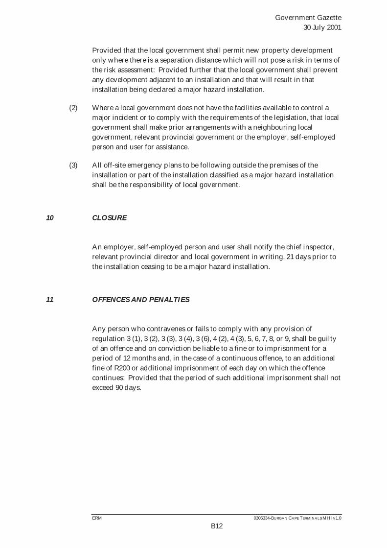
Government Gazette 30 July 2001
ERM 0305334-BURGAN CAPE TERMINALS MHI V1.0
B12
Provided that the local government shall permit new property development only where there is a separation distance which will not pose a risk in terms of the risk assessment: Provided further that the local government shall prevent any development adjacent to an installation and that will result in that installation being declared a major hazard installation.
(2) Where a local government does not have the facilities available to control a major incident or to comply with the requirements of the legislation, that local government shall make prior arrangements with a neighbouring local government, relevant provincial government or the employer, self-employed person and user for assistance.
(3) All off-site emergency plans to be following outside the premises of the installation or part of the installation classified as a major hazard installation shall be the responsibility of local government.
10 CLOSURE
An employer, self-employed person and user shall notify the chief inspector, relevant provincial director and local government in writing, 21 days prior to the installation ceasing to be a major hazard installation.
11 OFFENCES AND PENALTIES
Any person who contravenes or fails to comply with any provision of regulation 3 (1), 3 (2), 3 (3), 3 (4), 3 (6), 4 (2), 4 (3), 5, 6, 7, 8, or 9, shall be guilty of an offence and on conviction be liable to a fine or to imprisonment for a period of 12 months and, in the case of a continuous offence, to an additional fine of R200 or additional imprisonment of each day on which the offence continues: Provided that the period of such additional imprisonment shall not exceed 90 days.

Annex C
Material Safety Data Sheets (MSDS)

Annex D
Consequence Modelling Results
ERM 0305334-BURGAN CAPE TERMINALS MHI V1.0
D1
D CONSEQUENCE IMPACT AREAS (ISO-PLETHS)
D1 CONSEQUENCE ISO-PLETH CALCULATION
Modelling of conse4quences resulting from the ignition of released material from the bulk fuel installations have been performed using models within Phast 6.6.
D1.1 Inputs for Modelling Pool Fires
The pool fires were modelled using the parameters summarised in Table D.1.
Table D.1 Pool fire parameters
Flammable liquids modelled AGO, ULP, Ethanol and FAME Density of liquid (kg/m3) 850, 750, 800 and 800 kg/m3 Ambient (air) temperature ( C) 17°C (average) Relative humidity (%) 75.5% Wind velocity at 10 m (m/s) 2, 3,and 8 Figure D.1 illustrates the various consequence zones.
Figure D.1 Consequence Zone Representation
The detailed results of the bulk fuel installations consequence modelling appear in Table D.2 and Table D.3. Large flash fire and vapour cloud explosion consequence distances are taken from Buncefield literature and are identical for all tanks. The details of the Buncefield scenario modelling appear in Table D.4.

Tabl
e D
.2
Res
ults
of t
he P
ool F
ire M
odel
ling
– Fa
talit
y A
sses
smen
t
Nam
e D
escr
iptio
n R
elea
se R
ate
(kg/
s)
Igni
tion
Prob
abili
ty
Pool
Dia
met
er
(m)
Wea
ther
Th
erm
al F
lux
(kW
/m2)
Fr
eque
ncy:
D
ay
Freq
uenc
y:
Nig
ht
Con
sequ
ence
s
d (m
) c
(m)
s (m
) m
(m)
Die
sel_
Tank
s_2
S N
/A
1.00
E-01
35
B3
6.
3 kW
/m2
4.50
E+01
4.
50E+
01
42
30
-20
11
C8
6.3
kW/m
2 52
34
-1
8 17
F2
6.
3 kW
/m2
40
30
-22
9 B3
12
.5 k
W/m
2 22
20
-1
8 2
C8
12.5
kW
/m2
25
21
-18
3 F2
12
.5 k
W/m
2 22
20
-1
8 2
B3
37.5
kW
/m2
17
17
-17
0 C
8 37
.5 k
W/m
2 17
17
-1
7 0
F2
37.5
kW
/m2
17
17
-17
0 D
iese
l_Ta
nks_
2 L
N/A
1.
00E-
01
70
B3
6.3
kW/m
2 3.
00E+
01
3.00
E+01
68
50
-3
7 15
C
8 6.
3 kW
/m2
85
57
-35
25
F2
6.3
kW/m
2 64
50
-3
9 12
B3
12
.5 k
W/m
2 36
35
-3
6 0
C8
12.5
kW
/m2
38
37
-35
2 F2
12
.5 k
W/m
2 36
35
-3
5 0
B3
37.5
kW
/m2
35
35
-35
0 C
8 37
.5 k
W/m
2 35
35
-3
5 0
F2
37.5
kW
/m2
35
35
-35
0 D
iese
l_Ta
nks_
2 C
N
/A
1.50
E-03
12
2 B3
6.
3 kW
/m2
3.75
E-03
3.
75E-
03
108
83
-65
21
C8
6.3
kW/m
2 13
3 94
-6
0 37
F2
6.
3 kW
/m2
103
82
-68
17
B3
12.5
kW
/m2
62
62
-61
0 C
8 12
.5 k
W/m
2 66
62
-6
0 3
F2
12.5
kW
/m2
62
62
-61
0 B3
37
.5 k
W/m
2 61
61
-6
1 0
C8
37.5
kW
/m2
61
61
-61
0 F2
37
.5 k
W/m
2 61
61
-6
1 0
Die
sel_
Tank
s_3
w
1.23
E+03
1.
30E-
02
38
B3
6.3
kW/m
2 3.
12E-
03
3.12
E-03
45
32
-2
2 12
C
8 6.
3 kW
/m2
55
36
-20
18
F2
6.3
kW/m
2 42
31
-2
3 9

Nam
e D
escr
iptio
n R
elea
se R
ate
(kg/
s)
Igni
tion
Prob
abili
ty
Pool
Dia
met
er
(m)
Wea
ther
Th
erm
al F
lux
(kW
/m2)
Fr
eque
ncy:
D
ay
Freq
uenc
y:
Nig
ht
Con
sequ
ence
s
d (m
) c
(m)
s (m
) m
(m)
B3
12.5
kW
/m2
24
21
-20
2 C
8 12
.5 k
W/m
2 26
23
-2
0 3
F2
12.5
kW
/m2
23
21
-20
2 B3
37
.5 k
W/m
2 19
19
-1
9 0
C8
37.5
kW
/m2
19
19
-19
0 F2
37
.5 k
W/m
2 19
19
-1
9 0
Die
sel_
Tank
s_3
x 1.
23E+
01
1.57
E-03
38
B3
6.
3 kW
/m2
3.78
E-03
3.
78E-
03
45
32
-22
12
C8
6.3
kW/m
2 55
36
-2
0 18
F2
6.
3 kW
/m2
42
31
-23
9 B3
12
.5 k
W/m
2 24
21
-2
0 2
C8
12.5
kW
/m2
26
23
-20
3 F2
12
.5 k
W/m
2 23
21
-2
0 2
B3
37.5
kW
/m2
19
19
-19
0 C
8 37
.5 k
W/m
2 19
19
-1
9 0
F2
37.5
kW
/m2
19
19
-19
0 D
iese
l_Ta
nks_
4 b
3.15
E-01
1.
36E-
04
11
B3
6.3
kW/m
2 7.
95E-
04
7.95
E-04
27
18
-1
0 8
C8
6.3
kW/m
2 29
19
-8
11
F2
6.
3 kW
/m2
25
18
-11
7 B3
12
.5 k
W/m
2 17
11
-7
5
C8
12.5
kW
/m2
20
12
-7
6 F2
12
.5 k
W/m
2 15
10
-7
4
B3
37.5
kW
/m2
6 6
-6
0 C
8 37
.5 k
W/m
2 6
6 -6
0
F2
37.5
kW
/m2
6 6
-6
0 D
iese
l_Ta
nks_
4 c
1.23
E+01
1.
57E-
03
59
B3
6.3
kW/m
2 6.
44E-
03
6.44
E-03
60
44
-3
2 14
C
8 6.
3 kW
/m2
75
50
-30
23
F2
6.3
kW/m
2 56
43
-3
4 11
B3
12
.5 k
W/m
2 31
30
-3
0 1
C8
12.5
kW
/m2
33
32
-30
2 F2
12
.5 k
W/m
2 31
30
-3
0 0
B3
37.5
kW
/m2
29
29
-29
0 C
8 37
.5 k
W/m
2 29
29
-2
9 0
F2
37.5
kW
/m2
29
29
-29
0 D
iese
l_Ta
nks_
4 d
1.37
E+02
1.
30E-
02
100
B3
6.3
kW/m
2 3.
04E-
02
3.04
E-02
91
69
-5
3 19
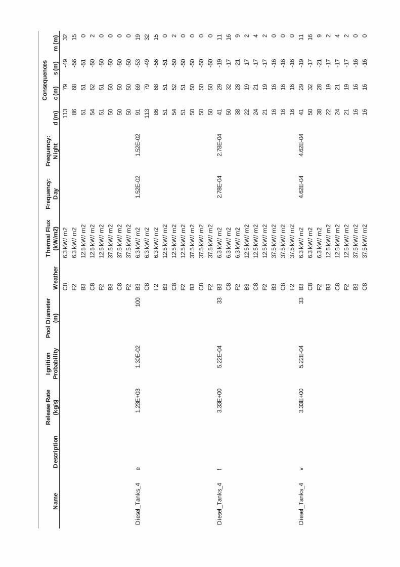
Nam
e D
escr
iptio
n R
elea
se R
ate
(kg/
s)
Igni
tion
Prob
abili
ty
Pool
Dia
met
er
(m)
Wea
ther
Th
erm
al F
lux
(kW
/m2)
Fr
eque
ncy:
D
ay
Freq
uenc
y:
Nig
ht
Con
sequ
ence
s
d (m
) c
(m)
s (m
) m
(m)
C8
6.3
kW/m
2 11
3 79
-4
9 32
F2
6.
3 kW
/m2
86
68
-56
15
B3
12.5
kW
/m2
51
51
-51
0 C
8 12
.5 k
W/m
2 54
52
-5
0 2
F2
12.5
kW
/m2
51
51
-50
0 B3
37
.5 k
W/m
2 50
50
-5
0 0
C8
37.5
kW
/m2
50
50
-50
0 F2
37
.5 k
W/m
2 50
50
-5
0 0
Die
sel_
Tank
s_4
e 1.
23E+
03
1.30
E-02
10
0 B3
6.
3 kW
/m2
1.52
E-02
1.
52E-
02
91
69
-53
19
C8
6.3
kW/m
2 11
3 79
-4
9 32
F2
6.
3 kW
/m2
86
68
-56
15
B3
12.5
kW
/m2
51
51
-51
0 C
8 12
.5 k
W/m
2 54
52
-5
0 2
F2
12.5
kW
/m2
51
51
-50
0 B3
37
.5 k
W/m
2 50
50
-5
0 0
C8
37.5
kW
/m2
50
50
-50
0 F2
37
.5 k
W/m
2 50
50
-5
0 0
Die
sel_
Tank
s_4
f 3.
33E+
00
5.22
E-04
33
B3
6.
3 kW
/m2
2.78
E-04
2.
78E-
04
41
29
-19
11
C8
6.3
kW/m
2 50
32
-1
7 16
F2
6.
3 kW
/m2
38
28
-21
9 B3
12
.5 k
W/m
2 22
19
-1
7 2
C8
12.5
kW
/m2
24
21
-17
4 F2
12
.5 k
W/m
2 21
19
-1
7 2
B3
37.5
kW
/m2
16
16
-16
0 C
8 37
.5 k
W/m
2 16
16
-1
6 0
F2
37.5
kW
/m2
16
16
-16
0 D
iese
l_Ta
nks_
4 v
3.33
E+00
5.
22E-
04
33
B3
6.3
kW/m
2 4.
62E-
04
4.62
E-04
41
29
-1
9 11
C
8 6.
3 kW
/m2
50
32
-17
16
F2
6.3
kW/m
2 38
28
-2
1 9
B3
12.5
kW
/m2
22
19
-17
2 C
8 12
.5 k
W/m
2 24
21
-1
7 4
F2
12.5
kW
/m2
21
19
-17
2 B3
37
.5 k
W/m
2 16
16
-1
6 0
C8
37.5
kW
/m2
16
16
-16
0

Nam
e D
escr
iptio
n R
elea
se R
ate
(kg/
s)
Igni
tion
Prob
abili
ty
Pool
Dia
met
er
(m)
Wea
ther
Th
erm
al F
lux
(kW
/m2)
Fr
eque
ncy:
D
ay
Freq
uenc
y:
Nig
ht
Con
sequ
ence
s
d (m
) c
(m)
s (m
) m
(m)
F2
37.5
kW
/m2
16
16
-16
0 D
iese
l_Ta
nks_
5 b
2.82
E-01
1.
30E-
04
11
B3
6.3
kW/m
2 8.
14E-
03
8.14
E-03
26
18
-1
0 8
C8
6.3
kW/m
2 29
19
-8
11
F2
6.
3 kW
/m2
24
18
-11
7 B3
12
.5 k
W/m
2 17
11
-7
5
C8
12.5
kW
/m2
20
12
-6
7 F2
12
.5 k
W/m
2 15
10
-7
4
B3
37.5
kW
/m2
5 5
-5
0 C
8 37
.5 k
W/m
2 5
5 -5
0
F2
37.5
kW
/m2
5 5
-5
0 D
iese
l_Ta
nks_
5 c
1.10
E+01
1.
42E-
03
56
B3
6.3
kW/m
2 6.
22E-
02
6.22
E-02
58
42
-3
0 14
C
8 6.
3 kW
/m2
72
48
-28
22
F2
6.3
kW/m
2 54
41
-3
2 11
B3
12
.5 k
W/m
2 30
29
-2
9 1
C8
12.5
kW
/m2
32
30
-28
2 F2
12
.5 k
W/m
2 30
29
-2
9 1
B3
37.5
kW
/m2
28
28
-28
0 C
8 37
.5 k
W/m
2 28
28
-2
8 0
F2
37.5
kW
/m2
28
28
-28
0 D
iese
l_Ta
nks_
5 d
8.45
E+01
1.
00E-
02
100
B3
6.3
kW/m
2 2.
50E-
01
2.50
E-01
91
69
-5
3 19
C
8 6.
3 kW
/m2
113
79
-49
32
F2
6.3
kW/m
2 86
68
-5
6 15
B3
12
.5 k
W/m
2 51
51
-5
1 0
C8
12.5
kW
/m2
54
52
-50
2 F2
12
.5 k
W/m
2 51
51
-5
0 0
B3
37.5
kW
/m2
50
50
-50
0 C
8 37
.5 k
W/m
2 50
50
-5
0 0
F2
37.5
kW
/m2
50
50
-50
0 D
iese
l_Ta
nks_
5 e
8.45
E+01
1.
00E-
02
100
B3
6.3
kW/m
2 1.
25E-
01
1.25
E-01
91
69
-5
3 19
C
8 6.
3 kW
/m2
113
79
-49
32
F2
6.3
kW/m
2 86
68
-5
6 15
B3
12
.5 k
W/m
2 51
51
-5
1 0
C8
12.5
kW
/m2
54
52
-50
2 F2
12
.5 k
W/m
2 51
51
-5
0 0

Nam
e D
escr
iptio
n R
elea
se R
ate
(kg/
s)
Igni
tion
Prob
abili
ty
Pool
Dia
met
er
(m)
Wea
ther
Th
erm
al F
lux
(kW
/m2)
Fr
eque
ncy:
D
ay
Freq
uenc
y:
Nig
ht
Con
sequ
ence
s
d (m
) c
(m)
s (m
) m
(m)
B3
37.5
kW
/m2
50
50
-50
0 C
8 37
.5 k
W/m
2 50
50
-5
0 0
F2
37.5
kW
/m2
50
50
-50
0 D
iese
l_Ta
nks_
5 f
2.98
E+00
4.
81E-
04
31
B3
6.3
kW/m
2 2.
76E-
03
2.76
E-03
40
28
-1
9 11
C
8 6.
3 kW
/m2
48
31
-17
16
F2
6.3
kW/m
2 37
28
-2
0 9
B3
12.5
kW
/m2
21
18
-17
2 C
8 12
.5 k
W/m
2 24
20
-1
6 4
F2
12.5
kW
/m2
21
18
-17
2 B3
37
.5 k
W/m
2 16
16
-1
6 0
C8
37.5
kW
/m2
16
16
-16
0 F2
37
.5 k
W/m
2 16
16
-1
6 0
Die
sel_
Tank
s_5
v 2.
98E+
00
4.81
E-04
31
B3
6.
3 kW
/m2
4.85
E-03
4.
85E-
03
40
28
-19
11
C8
6.3
kW/m
2 48
31
-1
7 16
F2
6.
3 kW
/m2
37
28
-20
9 B3
12
.5 k
W/m
2 21
18
-1
7 2
C8
12.5
kW
/m2
24
20
-16
4 F2
12
.5 k
W/m
2 21
18
-1
7 2
B3
37.5
kW
/m2
16
16
-16
0 C
8 37
.5 k
W/m
2 16
16
-1
6 0
F2
37.5
kW
/m2
16
16
-16
0 D
iese
l_Ta
nks_
6 S
N/A
1.
00E-
01
40
B3
6.3
kW/m
2 4.
50E+
01
4.50
E+01
46
33
-2
3 12
C
8 6.
3 kW
/m2
57
37
-21
18
F2
6.3
kW/m
2 43
32
-2
4 10
B3
12
.5 k
W/m
2 24
22
-2
1 2
C8
12.5
kW
/m2
27
24
-21
3 F2
12
.5 k
W/m
2 24
22
-2
1 1
B3
37.5
kW
/m2
20
20
-20
0 C
8 37
.5 k
W/m
2 20
20
-2
0 0
F2
37.5
kW
/m2
20
20
-20
0 D
iese
l_Ta
nks_
6 L
N/A
1.
00E-
01
80
B3
6.3
kW/m
2 3.
00E+
01
3.00
E+01
76
57
-4
3 17
C
8 6.
3 kW
/m2
95
64
-40
27
F2
6.3
kW/m
2 72
56
-4
5 13
B3
12
.5 k
W/m
2 41
40
-4
1 0

Nam
e D
escr
iptio
n R
elea
se R
ate
(kg/
s)
Igni
tion
Prob
abili
ty
Pool
Dia
met
er
(m)
Wea
ther
Th
erm
al F
lux
(kW
/m2)
Fr
eque
ncy:
D
ay
Freq
uenc
y:
Nig
ht
Con
sequ
ence
s
d (m
) c
(m)
s (m
) m
(m)
C8
12.5
kW
/m2
43
42
-40
2 F2
12
.5 k
W/m
2 41
40
-4
1 0
B3
37.5
kW
/m2
40
40
-40
0 C
8 37
.5 k
W/m
2 40
40
-4
0 0
F2
37.5
kW
/m2
40
40
-40
0 D
iese
l_Ta
nks_
6 C
N
/A
1.50
E-03
12
8 B3
6.
3 kW
/m2
3.75
E-03
3.
75E-
03
112
87
-69
22
C8
6.3
kW/m
2 13
9 98
-6
3 38
F2
6.
3 kW
/m2
107
86
-72
18
B3
12.5
kW
/m2
66
65
-64
1 C
8 12
.5 k
W/m
2 69
66
-6
3 3
F2
12.5
kW
/m2
66
65
-64
1 B3
37
.5 k
W/m
2 64
64
-6
4 0
C8
37.5
kW
/m2
64
64
-64
0 F2
37
.5 k
W/m
2 64
64
-6
4 0
Die
sel_
Tank
s_7
S N
/A
1.00
E-01
34
B3
6.
3 kW
/m2
4.50
E+01
4.
50E+
01
42
30
-20
11
C8
6.3
kW/m
2 51
33
-1
8 17
F2
6.
3 kW
/m2
39
29
-21
9 B3
12
.5 k
W/m
2 22
19
-1
8 2
C8
12.5
kW
/m2
25
21
-18
3 F2
12
.5 k
W/m
2 22
19
-1
8 2
B3
37.5
kW
/m2
17
17
-17
0 C
8 37
.5 k
W/m
2 17
17
-1
7 0
F2
37.5
kW
/m2
17
17
-17
0 D
iese
l_Ta
nks_
7 L
N/A
1.
00E-
01
68
B3
6.3
kW/m
2 3.
00E+
01
3.00
E+01
67
50
-3
7 15
C
8 6.
3 kW
/m2
84
56
-34
25
F2
6.3
kW/m
2 63
49
-3
9 12
B3
12
.5 k
W/m
2 35
35
-3
5 0
C8
12.5
kW
/m2
38
36
-34
2 F2
12
.5 k
W/m
2 35
35
-3
5 0
B3
37.5
kW
/m2
34
34
-34
0 C
8 37
.5 k
W/m
2 34
34
-3
4 0
F2
37.5
kW
/m2
34
34
-34
0 D
iese
l_Ta
nks_
7 C
N
/A
1.50
E-03
12
1 B3
6.
3 kW
/m2
3.75
E-03
3.
75E-
03
107
83
-65
21
C8
6.3
kW/m
2 13
3 94
-6
0 37

Nam
e D
escr
iptio
n R
elea
se R
ate
(kg/
s)
Igni
tion
Prob
abili
ty
Pool
Dia
met
er
(m)
Wea
ther
Th
erm
al F
lux
(kW
/m2)
Fr
eque
ncy:
D
ay
Freq
uenc
y:
Nig
ht
Con
sequ
ence
s
d (m
) c
(m)
s (m
) m
(m)
F2
6.3
kW/m
2 10
2 82
-6
8 17
B3
12
.5 k
W/m
2 62
61
-6
1 0
C8
12.5
kW
/m2
65
62
-60
3 F2
12
.5 k
W/m
2 62
62
-6
1 0
B3
37.5
kW
/m2
61
61
-61
0 C
8 37
.5 k
W/m
2 61
61
-6
1 0
F2
37.5
kW
/m2
61
61
-61
0 D
iese
l_Ta
nks_
8 S
N/A
1.
00E-
01
43
B3
6.3
kW/m
2 4.
50E+
01
4.50
E+01
48
35
-2
4 12
C
8 6.
3 kW
/m2
59
39
-22
19
F2
6.3
kW/m
2 45
34
-2
5 10
B3
12
.5 k
W/m
2 25
23
-2
2 1
C8
12.5
kW
/m2
27
25
-22
3 F2
12
.5 k
W/m
2 25
23
-2
2 1
B3
37.5
kW
/m2
21
21
-21
0 C
8 37
.5 k
W/m
2 21
21
-2
1 0
F2
37.5
kW
/m2
21
21
-21
0 D
iese
l_Ta
nks_
8 L
N/A
1.
00E-
01
85
B3
6.3
kW/m
2 3.
00E+
01
3.00
E+01
80
60
-4
5 17
C
8 6.
3 kW
/m2
100
68
-42
29
F2
6.3
kW/m
2 76
59
-4
8 14
B3
12
.5 k
W/m
2 43
43
-4
3 0
C8
12.5
kW
/m2
46
44
-43
2 F2
12
.5 k
W/m
2 43
43
-4
3 0
B3
37.5
kW
/m2
43
43
-43
0 C
8 37
.5 k
W/m
2 43
43
-4
3 0
F2
37.5
kW
/m2
43
43
-43
0 D
iese
l_Ta
nks_
8 C
N
/A
1.50
E-03
13
2 B3
6.
3 kW
/m2
3.75
E-03
3.
75E-
03
115
89
-71
22
C8
6.3
kW/m
2 14
2 10
1 -6
5 39
F2
6.
3 kW
/m2
110
89
-74
18
B3
12.5
kW
/m2
68
67
-66
1 C
8 12
.5 k
W/m
2 71
67
-6
5 3
F2
12.5
kW
/m2
67
67
-66
1 B3
37
.5 k
W/m
2 66
66
-6
6 0
C8
37.5
kW
/m2
66
66
-66
0 F2
37
.5 k
W/m
2 66
66
-6
6 0

Nam
e D
escr
iptio
n R
elea
se R
ate
(kg/
s)
Igni
tion
Prob
abili
ty
Pool
Dia
met
er
(m)
Wea
ther
Th
erm
al F
lux
(kW
/m2)
Fr
eque
ncy:
D
ay
Freq
uenc
y:
Nig
ht
Con
sequ
ence
s
d (m
) c
(m)
s (m
) m
(m)
Die
sel_
Tank
s_9
S N
/A
1.00
E-01
50
B3
6.
3 kW
/m2
4.50
E+01
4.
50E+
01
54
39
-27
13
C8
6.3
kW/m
2 67
44
-2
6 20
F2
6.
3 kW
/m2
50
38
-29
11
B3
12.5
kW
/m2
28
26
-26
1 C
8 12
.5 k
W/m
2 30
28
-2
6 2
F2
12.5
kW
/m2
27
26
-26
1 B3
37
.5 k
W/m
2 25
25
-2
5 0
C8
37.5
kW
/m2
25
25
-25
0 F2
37
.5 k
W/m
2 25
25
-2
5 0
Die
sel_
Tank
s_9
L N
/A
1.00
E-01
10
1 B3
6.
3 kW
/m2
3.00
E+01
3.
00E+
01
91
70
-54
19
C8
6.3
kW/m
2 11
4 79
-5
0 32
F2
6.
3 kW
/m2
87
69
-56
15
B3
12.5
kW
/m2
51
51
-51
0 C
8 12
.5 k
W/m
2 54
52
-5
0 2
F2
12.5
kW
/m2
51
51
-51
0 B3
37
.5 k
W/m
2 50
50
-5
0 0
C8
37.5
kW
/m2
50
50
-50
0 F2
37
.5 k
W/m
2 50
50
-5
0 0
Die
sel_
Tank
s_9
C
N/A
1.
50E-
03
142
B3
6.3
kW/m
2 3.
75E-
03
3.75
E-03
12
3 96
-7
6 23
C
8 6.
3 kW
/m2
151
108
-70
41
F2
6.3
kW/m
2 11
7 95
-8
0 19
B3
12
.5 k
W/m
2 73
72
-7
1 1
C8
12.5
kW
/m2
77
73
-70
4 F2
12
.5 k
W/m
2 73
72
-7
1 1
B3
37.5
kW
/m2
71
71
-71
0 C
8 37
.5 k
W/m
2 71
71
-7
1 0
F2
37.5
kW
/m2
71
71
-71
0 D
iese
l_Ta
nks_
10
S N
/A
1.00
E-01
50
B3
6.
3 kW
/m2
4.50
E+01
4.
50E+
01
54
39
-27
13
C8
6.3
kW/m
2 67
44
-2
6 20
F2
6.
3 kW
/m2
50
38
-29
11
B3
12.5
kW
/m2
28
26
-26
1 C
8 12
.5 k
W/m
2 30
28
-2
6 2
F2
12.5
kW
/m2
27
26
-26
1 B3
37
.5 k
W/m
2 25
25
-2
5 0

Nam
e D
escr
iptio
n R
elea
se R
ate
(kg/
s)
Igni
tion
Prob
abili
ty
Pool
Dia
met
er
(m)
Wea
ther
Th
erm
al F
lux
(kW
/m2)
Fr
eque
ncy:
D
ay
Freq
uenc
y:
Nig
ht
Con
sequ
ence
s
d (m
) c
(m)
s (m
) m
(m)
C8
37.5
kW
/m2
25
25
-25
0 F2
37
.5 k
W/m
2 25
25
-2
5 0
Die
sel_
Tank
s_10
L
N/A
1.
00E-
01
101
B3
6.3
kW/m
2 3.
00E+
01
3.00
E+01
91
70
-5
4 19
C
8 6.
3 kW
/m2
114
79
-50
32
F2
6.3
kW/m
2 87
69
-5
6 15
B3
12
.5 k
W/m
2 51
51
-5
1 0
C8
12.5
kW
/m2
54
52
-50
2 F2
12
.5 k
W/m
2 51
51
-5
1 0
B3
37.5
kW
/m2
50
50
-50
0 C
8 37
.5 k
W/m
2 50
50
-5
0 0
F2
37.5
kW
/m2
50
50
-50
0 D
iese
l_Ta
nks_
10
C
N/A
1.
50E-
03
142
B3
6.3
kW/m
2 3.
75E-
03
3.75
E-03
12
3 96
-7
6 23
C
8 6.
3 kW
/m2
151
108
-70
41
F2
6.3
kW/m
2 11
7 95
-8
0 19
B3
12
.5 k
W/m
2 73
72
-7
1 1
C8
12.5
kW
/m2
77
73
-70
4 F2
12
.5 k
W/m
2 73
72
-7
1 1
B3
37.5
kW
/m2
71
71
-71
0 C
8 37
.5 k
W/m
2 71
71
-7
1 0
F2
37.5
kW
/m2
71
71
-71
0 D
iese
l_Ta
nks_
11
S N
/A
1.00
E-01
44
B3
6.
3 kW
/m2
4.50
E+01
4.
50E+
01
49
35
-24
12
C8
6.3
kW/m
2 60
40
-2
3 19
F2
6.
3 kW
/m2
46
34
-26
10
B3
12.5
kW
/m2
25
24
-23
1 C
8 12
.5 k
W/m
2 28
25
-2
2 3
F2
12.5
kW
/m2
25
23
-23
1 B3
37
.5 k
W/m
2 22
22
-2
2 0
C8
37.5
kW
/m2
22
22
-22
0 F2
37
.5 k
W/m
2 22
22
-2
2 0
Die
sel_
Tank
s_11
L
N/A
1.
00E-
01
87
B3
6.3
kW/m
2 3.
00E+
01
3.00
E+01
81
61
-4
7 17
C
8 6.
3 kW
/m2
102
70
-43
29
F2
6.3
kW/m
2 77
60
-4
9 14
B3
12
.5 k
W/m
2 44
44
-4
4 0
C8
12.5
kW
/m2
47
45
-44
2
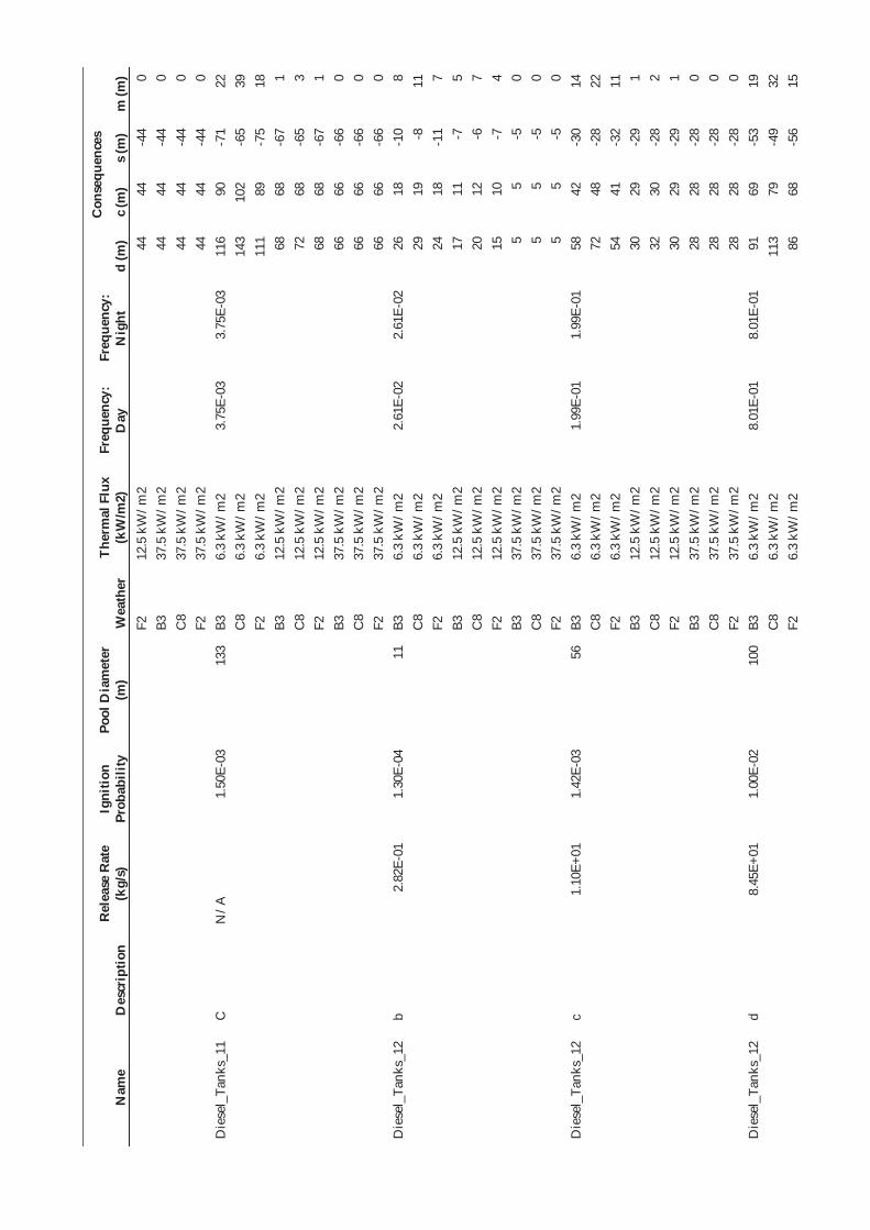
Nam
e D
escr
iptio
n R
elea
se R
ate
(kg/
s)
Igni
tion
Prob
abili
ty
Pool
Dia
met
er
(m)
Wea
ther
Th
erm
al F
lux
(kW
/m2)
Fr
eque
ncy:
D
ay
Freq
uenc
y:
Nig
ht
Con
sequ
ence
s
d (m
) c
(m)
s (m
) m
(m)
F2
12.5
kW
/m2
44
44
-44
0 B3
37
.5 k
W/m
2 44
44
-4
4 0
C8
37.5
kW
/m2
44
44
-44
0 F2
37
.5 k
W/m
2 44
44
-4
4 0
Die
sel_
Tank
s_11
C
N
/A
1.50
E-03
13
3 B3
6.
3 kW
/m2
3.75
E-03
3.
75E-
03
116
90
-71
22
C8
6.3
kW/m
2 14
3 10
2 -6
5 39
F2
6.
3 kW
/m2
111
89
-75
18
B3
12.5
kW
/m2
68
68
-67
1 C
8 12
.5 k
W/m
2 72
68
-6
5 3
F2
12.5
kW
/m2
68
68
-67
1 B3
37
.5 k
W/m
2 66
66
-6
6 0
C8
37.5
kW
/m2
66
66
-66
0 F2
37
.5 k
W/m
2 66
66
-6
6 0
Die
sel_
Tank
s_12
b
2.82
E-01
1.
30E-
04
11
B3
6.3
kW/m
2 2.
61E-
02
2.61
E-02
26
18
-1
0 8
C8
6.3
kW/m
2 29
19
-8
11
F2
6.
3 kW
/m2
24
18
-11
7 B3
12
.5 k
W/m
2 17
11
-7
5
C8
12.5
kW
/m2
20
12
-6
7 F2
12
.5 k
W/m
2 15
10
-7
4
B3
37.5
kW
/m2
5 5
-5
0 C
8 37
.5 k
W/m
2 5
5 -5
0
F2
37.5
kW
/m2
5 5
-5
0 D
iese
l_Ta
nks_
12
c 1.
10E+
01
1.42
E-03
56
B3
6.
3 kW
/m2
1.99
E-01
1.
99E-
01
58
42
-30
14
C8
6.3
kW/m
2 72
48
-2
8 22
F2
6.
3 kW
/m2
54
41
-32
11
B3
12.5
kW
/m2
30
29
-29
1 C
8 12
.5 k
W/m
2 32
30
-2
8 2
F2
12.5
kW
/m2
30
29
-29
1 B3
37
.5 k
W/m
2 28
28
-2
8 0
C8
37.5
kW
/m2
28
28
-28
0 F2
37
.5 k
W/m
2 28
28
-2
8 0
Die
sel_
Tank
s_12
d
8.45
E+01
1.
00E-
02
100
B3
6.3
kW/m
2 8.
01E-
01
8.01
E-01
91
69
-5
3 19
C
8 6.
3 kW
/m2
113
79
-49
32
F2
6.3
kW/m
2 86
68
-5
6 15

Nam
e D
escr
iptio
n R
elea
se R
ate
(kg/
s)
Igni
tion
Prob
abili
ty
Pool
Dia
met
er
(m)
Wea
ther
Th
erm
al F
lux
(kW
/m2)
Fr
eque
ncy:
D
ay
Freq
uenc
y:
Nig
ht
Con
sequ
ence
s
d (m
) c
(m)
s (m
) m
(m)
B3
12.5
kW
/m2
51
51
-51
0 C
8 12
.5 k
W/m
2 54
52
-5
0 2
F2
12.5
kW
/m2
51
51
-50
0 B3
37
.5 k
W/m
2 50
50
-5
0 0
C8
37.5
kW
/m2
50
50
-50
0 F2
37
.5 k
W/m
2 50
50
-5
0 0
Die
sel_
Tank
s_12
e
8.45
E+01
1.
00E-
02
100
B3
6.3
kW/m
2 4.
01E-
01
4.01
E-01
91
69
-5
3 19
C
8 6.
3 kW
/m2
113
79
-49
32
F2
6.3
kW/m
2 86
68
-5
6 15
B3
12
.5 k
W/m
2 51
51
-5
1 0
C8
12.5
kW
/m2
54
52
-50
2 F2
12
.5 k
W/m
2 51
51
-5
0 0
B3
37.5
kW
/m2
50
50
-50
0 C
8 37
.5 k
W/m
2 50
50
-5
0 0
F2
37.5
kW
/m2
50
50
-50
0 D
iese
l_Ta
nks_
12
f 2.
98E+
00
4.81
E-04
31
B3
6.
3 kW
/m2
8.77
E-03
8.
77E-
03
40
28
-19
11
C8
6.3
kW/m
2 48
31
-1
7 16
F2
6.
3 kW
/m2
37
28
-20
9 B3
12
.5 k
W/m
2 21
18
-1
7 2
C8
12.5
kW
/m2
24
20
-16
4 F2
12
.5 k
W/m
2 21
18
-1
7 2
B3
37.5
kW
/m2
16
16
-16
0 C
8 37
.5 k
W/m
2 16
16
-1
6 0
F2
37.5
kW
/m2
16
16
-16
0 D
iese
l_Ta
nks_
12
v 2.
98E+
00
4.81
E-04
31
B3
6.
3 kW
/m2
1.33
E-02
1.
33E-
02
40
28
-19
11
C8
6.3
kW/m
2 48
31
-1
7 16
F2
6.
3 kW
/m2
37
28
-20
9 B3
12
.5 k
W/m
2 21
18
-1
7 2
C8
12.5
kW
/m2
24
20
-16
4 F2
12
.5 k
W/m
2 21
18
-1
7 2
B3
37.5
kW
/m2
16
16
-16
0 C
8 37
.5 k
W/m
2 16
16
-1
6 0
F2
37.5
kW
/m2
16
16
-16
0 D
iese
l_Ta
nks_
13
b 2.
82E-
01
1.04
E-04
11
B3
6.
3 kW
/m2
1.87
E-03
1.
87E-
03
26
18
-10
8

Nam
e D
escr
iptio
n R
elea
se R
ate
(kg/
s)
Igni
tion
Prob
abili
ty
Pool
Dia
met
er
(m)
Wea
ther
Th
erm
al F
lux
(kW
/m2)
Fr
eque
ncy:
D
ay
Freq
uenc
y:
Nig
ht
Con
sequ
ence
s
d (m
) c
(m)
s (m
) m
(m)
C8
6.3
kW/m
2 29
19
-8
11
F2
6.
3 kW
/m2
24
18
-11
7 B3
12
.5 k
W/m
2 17
11
-7
5
C8
12.5
kW
/m2
20
12
-6
7 F2
12
.5 k
W/m
2 15
10
-7
4
B3
37.5
kW
/m2
5 5
-5
0 C
8 37
.5 k
W/m
2 5
5 -5
0
F2
37.5
kW
/m2
5 5
-5
0 D
iese
l_Ta
nks_
13
c 1.
10E+
01
3.96
E-04
30
B3
6.
3 kW
/m2
4.46
E-03
4.
46E-
03
39
28
-18
11
C8
6.3
kW/m
2 47
31
-1
6 15
F2
6.
3 kW
/m2
37
27
-19
9 B3
12
.5 k
W/m
2 21
18
-1
6 3
C8
12.5
kW
/m2
24
19
-16
4 F2
12
.5 k
W/m
2 20
18
-1
6 2
B3
37.5
kW
/m2
15
15
-15
0 C
8 37
.5 k
W/m
2 15
15
-1
5 0
F2
37.5
kW
/m2
15
15
-15
0 D
iese
l_Ta
nks_
13
d 8.
45E+
01
1.50
E-03
30
B3
6.
3 kW
/m2
6.75
E-03
6.
75E-
03
39
28
-18
11
C8
6.3
kW/m
2 47
31
-1
6 15
F2
6.
3 kW
/m2
37
27
-19
9 B3
12
.5 k
W/m
2 21
18
-1
6 3
C8
12.5
kW
/m2
24
19
-16
4 F2
12
.5 k
W/m
2 20
18
-1
6 2
B3
37.5
kW
/m2
15
15
-15
0 C
8 37
.5 k
W/m
2 15
15
-1
5 0
F2
37.5
kW
/m2
15
15
-15
0 D
iese
l_Ta
nks_
13
e 8.
45E+
01
1.50
E-03
30
B3
6.
3 kW
/m2
2.36
E-03
2.
36E-
03
39
28
-18
11
C8
6.3
kW/m
2 47
31
-1
6 15
F2
6.
3 kW
/m2
37
27
-19
9 B3
12
.5 k
W/m
2 21
18
-1
6 3
C8
12.5
kW
/m2
24
19
-16
4 F2
12
.5 k
W/m
2 20
18
-1
6 2
B3
37.5
kW
/m2
15
15
-15
0 C
8 37
.5 k
W/m
2 15
15
-1
5 0

Nam
e D
escr
iptio
n R
elea
se R
ate
(kg/
s)
Igni
tion
Prob
abili
ty
Pool
Dia
met
er
(m)
Wea
ther
Th
erm
al F
lux
(kW
/m2)
Fr
eque
ncy:
D
ay
Freq
uenc
y:
Nig
ht
Con
sequ
ence
s
d (m
) c
(m)
s (m
) m
(m)
F2
37.5
kW
/m2
15
15
-15
0 D
iese
l_Ta
nks_
13
f 2.
98E+
00
1.73
E-04
30
B3
6.
3 kW
/m2
4.60
E-04
4.
60E-
04
39
28
-18
11
C8
6.3
kW/m
2 47
31
-1
6 15
F2
6.
3 kW
/m2
37
27
-19
9 B3
12
.5 k
W/m
2 21
18
-1
6 3
C8
12.5
kW
/m2
24
19
-16
4 F2
12
.5 k
W/m
2 20
18
-1
6 2
B3
37.5
kW
/m2
15
15
-15
0 C
8 37
.5 k
W/m
2 15
15
-1
5 0
F2
37.5
kW
/m2
15
15
-15
0 D
iese
l_Ta
nks_
13
v 2.
98E+
00
1.73
E-04
30
B3
6.
3 kW
/m2
1.12
E-03
1.
12E-
03
39
28
-18
11
C8
6.3
kW/m
2 47
31
-1
6 15
F2
6.
3 kW
/m2
37
27
-19
9 B3
12
.5 k
W/m
2 21
18
-1
6 3
C8
12.5
kW
/m2
24
19
-16
4 F2
12
.5 k
W/m
2 20
18
-1
6 2
B3
37.5
kW
/m2
15
15
-15
0 C
8 37
.5 k
W/m
2 15
15
-1
5 0
F2
37.5
kW
/m2
15
15
-15
0 D
iese
l_Ta
nks_
14
b 2.
82E-
01
1.04
E-04
11
B3
6.
3 kW
/m2
1.87
E-03
1.
87E-
03
26
18
-10
8 C
8 6.
3 kW
/m2
29
19
-8
11
F2
6.3
kW/m
2 24
18
-1
1 7
B3
12.5
kW
/m2
17
11
-7
5 C
8 12
.5 k
W/m
2 20
12
-6
7
F2
12.5
kW
/m2
15
10
-7
4 B3
37
.5 k
W/m
2 5
5 -5
0
C8
37.5
kW
/m2
5 5
-5
0 F2
37
.5 k
W/m
2 5
5 -5
0
Die
sel_
Tank
s_14
c
1.10
E+01
3.
96E-
04
31
B3
6.3
kW/m
2 4.
46E-
03
4.46
E-03
40
28
-1
9 11
C
8 6.
3 kW
/m2
48
31
-17
16
F2
6.3
kW/m
2 37
28
-2
0 9
B3
12.5
kW
/m2
21
18
-17
2 C
8 12
.5 k
W/m
2 24
20
-1
6 4
F2
12.5
kW
/m2
21
18
-17
2

Nam
e D
escr
iptio
n R
elea
se R
ate
(kg/
s)
Igni
tion
Prob
abili
ty
Pool
Dia
met
er
(m)
Wea
ther
Th
erm
al F
lux
(kW
/m2)
Fr
eque
ncy:
D
ay
Freq
uenc
y:
Nig
ht
Con
sequ
ence
s
d (m
) c
(m)
s (m
) m
(m)
B3
37.5
kW
/m2
16
16
-16
0 C
8 37
.5 k
W/m
2 16
16
-1
6 0
F2
37.5
kW
/m2
16
16
-16
0 D
iese
l_Ta
nks_
14
d 8.
45E+
01
1.50
E-03
31
B3
6.
3 kW
/m2
6.75
E-03
6.
75E-
03
40
28
-19
11
C8
6.3
kW/m
2 48
31
-1
7 16
F2
6.
3 kW
/m2
37
28
-20
9 B3
12
.5 k
W/m
2 21
18
-1
7 2
C8
12.5
kW
/m2
24
20
-16
4 F2
12
.5 k
W/m
2 21
18
-1
7 2
B3
37.5
kW
/m2
16
16
-16
0 C
8 37
.5 k
W/m
2 16
16
-1
6 0
F2
37.5
kW
/m2
16
16
-16
0 D
iese
l_Ta
nks_
14
e 8.
45E+
01
1.50
E-03
31
B3
6.
3 kW
/m2
2.36
E-03
2.
36E-
03
40
28
-19
11
C8
6.3
kW/m
2 48
31
-1
7 16
F2
6.
3 kW
/m2
37
28
-20
9 B3
12
.5 k
W/m
2 21
18
-1
7 2
C8
12.5
kW
/m2
24
20
-16
4 F2
12
.5 k
W/m
2 21
18
-1
7 2
B3
37.5
kW
/m2
16
16
-16
0 C
8 37
.5 k
W/m
2 16
16
-1
6 0
F2
37.5
kW
/m2
16
16
-16
0 D
iese
l_Ta
nks_
14
f 2.
98E+
00
1.73
E-04
31
B3
6.
3 kW
/m2
4.60
E-04
4.
60E-
04
40
28
-19
11
C8
6.3
kW/m
2 48
31
-1
7 16
F2
6.
3 kW
/m2
37
28
-20
9 B3
12
.5 k
W/m
2 21
18
-1
7 2
C8
12.5
kW
/m2
24
20
-16
4 F2
12
.5 k
W/m
2 21
18
-1
7 2
B3
37.5
kW
/m2
16
16
-16
0 C
8 37
.5 k
W/m
2 16
16
-1
6 0
F2
37.5
kW
/m2
16
16
-16
0 D
iese
l_Ta
nks_
14
v 2.
98E+
00
1.73
E-04
31
B3
6.
3 kW
/m2
1.12
E-03
1.
12E-
03
40
28
-19
11
C8
6.3
kW/m
2 48
31
-1
7 16
F2
6.
3 kW
/m2
37
28
-20
9 B3
12
.5 k
W/m
2 21
18
-1
7 2
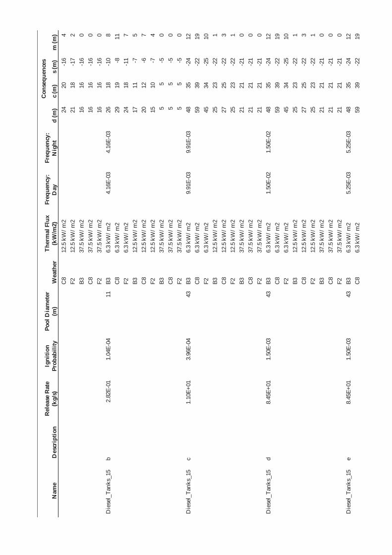
Nam
e D
escr
iptio
n R
elea
se R
ate
(kg/
s)
Igni
tion
Prob
abili
ty
Pool
Dia
met
er
(m)
Wea
ther
Th
erm
al F
lux
(kW
/m2)
Fr
eque
ncy:
D
ay
Freq
uenc
y:
Nig
ht
Con
sequ
ence
s
d (m
) c
(m)
s (m
) m
(m)
C8
12.5
kW
/m2
24
20
-16
4 F2
12
.5 k
W/m
2 21
18
-1
7 2
B3
37.5
kW
/m2
16
16
-16
0 C
8 37
.5 k
W/m
2 16
16
-1
6 0
F2
37.5
kW
/m2
16
16
-16
0 D
iese
l_Ta
nks_
15
b 2.
82E-
01
1.04
E-04
11
B3
6.
3 kW
/m2
4.16
E-03
4.
16E-
03
26
18
-10
8 C
8 6.
3 kW
/m2
29
19
-8
11
F2
6.3
kW/m
2 24
18
-1
1 7
B3
12.5
kW
/m2
17
11
-7
5 C
8 12
.5 k
W/m
2 20
12
-6
7
F2
12.5
kW
/m2
15
10
-7
4 B3
37
.5 k
W/m
2 5
5 -5
0
C8
37.5
kW
/m2
5 5
-5
0 F2
37
.5 k
W/m
2 5
5 -5
0
Die
sel_
Tank
s_15
c
1.10
E+01
3.
96E-
04
43
B3
6.3
kW/m
2 9.
91E-
03
9.91
E-03
48
35
-2
4 12
C
8 6.
3 kW
/m2
59
39
-22
19
F2
6.3
kW/m
2 45
34
-2
5 10
B3
12
.5 k
W/m
2 25
23
-2
2 1
C8
12.5
kW
/m2
27
25
-22
3 F2
12
.5 k
W/m
2 25
23
-2
2 1
B3
37.5
kW
/m2
21
21
-21
0 C
8 37
.5 k
W/m
2 21
21
-2
1 0
F2
37.5
kW
/m2
21
21
-21
0 D
iese
l_Ta
nks_
15
d 8.
45E+
01
1.50
E-03
43
B3
6.
3 kW
/m2
1.50
E-02
1.
50E-
02
48
35
-24
12
C8
6.3
kW/m
2 59
39
-2
2 19
F2
6.
3 kW
/m2
45
34
-25
10
B3
12.5
kW
/m2
25
23
-22
1 C
8 12
.5 k
W/m
2 27
25
-2
2 3
F2
12.5
kW
/m2
25
23
-22
1 B3
37
.5 k
W/m
2 21
21
-2
1 0
C8
37.5
kW
/m2
21
21
-21
0 F2
37
.5 k
W/m
2 21
21
-2
1 0
Die
sel_
Tank
s_15
e
8.45
E+01
1.
50E-
03
43
B3
6.3
kW/m
2 5.
25E-
03
5.25
E-03
48
35
-2
4 12
C
8 6.
3 kW
/m2
59
39
-22
19
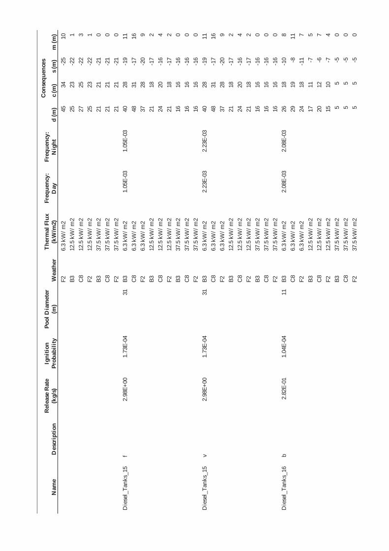
Nam
e D
escr
iptio
n R
elea
se R
ate
(kg/
s)
Igni
tion
Prob
abili
ty
Pool
Dia
met
er
(m)
Wea
ther
Th
erm
al F
lux
(kW
/m2)
Fr
eque
ncy:
D
ay
Freq
uenc
y:
Nig
ht
Con
sequ
ence
s
d (m
) c
(m)
s (m
) m
(m)
F2
6.3
kW/m
2 45
34
-2
5 10
B3
12
.5 k
W/m
2 25
23
-2
2 1
C8
12.5
kW
/m2
27
25
-22
3 F2
12
.5 k
W/m
2 25
23
-2
2 1
B3
37.5
kW
/m2
21
21
-21
0 C
8 37
.5 k
W/m
2 21
21
-2
1 0
F2
37.5
kW
/m2
21
21
-21
0 D
iese
l_Ta
nks_
15
f 2.
98E+
00
1.73
E-04
31
B3
6.
3 kW
/m2
1.05
E-03
1.
05E-
03
40
28
-19
11
C8
6.3
kW/m
2 48
31
-1
7 16
F2
6.
3 kW
/m2
37
28
-20
9 B3
12
.5 k
W/m
2 21
18
-1
7 2
C8
12.5
kW
/m2
24
20
-16
4 F2
12
.5 k
W/m
2 21
18
-1
7 2
B3
37.5
kW
/m2
16
16
-16
0 C
8 37
.5 k
W/m
2 16
16
-1
6 0
F2
37.5
kW
/m2
16
16
-16
0 D
iese
l_Ta
nks_
15
v 2.
98E+
00
1.73
E-04
31
B3
6.
3 kW
/m2
2.23
E-03
2.
23E-
03
40
28
-19
11
C8
6.3
kW/m
2 48
31
-1
7 16
F2
6.
3 kW
/m2
37
28
-20
9 B3
12
.5 k
W/m
2 21
18
-1
7 2
C8
12.5
kW
/m2
24
20
-16
4 F2
12
.5 k
W/m
2 21
18
-1
7 2
B3
37.5
kW
/m2
16
16
-16
0 C
8 37
.5 k
W/m
2 16
16
-1
6 0
F2
37.5
kW
/m2
16
16
-16
0 D
iese
l_Ta
nks_
16
b 2.
82E-
01
1.04
E-04
11
B3
6.
3 kW
/m2
2.08
E-03
2.
08E-
03
26
18
-10
8 C
8 6.
3 kW
/m2
29
19
-8
11
F2
6.3
kW/m
2 24
18
-1
1 7
B3
12.5
kW
/m2
17
11
-7
5 C
8 12
.5 k
W/m
2 20
12
-6
7
F2
12.5
kW
/m2
15
10
-7
4 B3
37
.5 k
W/m
2 5
5 -5
0
C8
37.5
kW
/m2
5 5
-5
0 F2
37
.5 k
W/m
2 5
5 -5
0

Nam
e D
escr
iptio
n R
elea
se R
ate
(kg/
s)
Igni
tion
Prob
abili
ty
Pool
Dia
met
er
(m)
Wea
ther
Th
erm
al F
lux
(kW
/m2)
Fr
eque
ncy:
D
ay
Freq
uenc
y:
Nig
ht
Con
sequ
ence
s
d (m
) c
(m)
s (m
) m
(m)
Die
sel_
Tank
s_16
c
1.10
E+01
3.
96E-
04
33
B3
6.3
kW/m
2 4.
95E-
03
4.95
E-03
41
29
-1
9 11
C
8 6.
3 kW
/m2
50
33
-18
16
F2
6.3
kW/m
2 39
29
-2
1 9
B3
12.5
kW
/m2
22
19
-17
2 C
8 12
.5 k
W/m
2 24
21
-1
7 4
F2
12.5
kW
/m2
21
19
-17
2 B3
37
.5 k
W/m
2 17
17
-1
7 0
C8
37.5
kW
/m2
17
17
-17
0 F2
37
.5 k
W/m
2 17
17
-1
7 0
Die
sel_
Tank
s_16
d
8.45
E+01
1.
50E-
03
33
B3
6.3
kW/m
2 7.
50E-
03
7.50
E-03
41
29
-1
9 11
C
8 6.
3 kW
/m2
50
33
-18
16
F2
6.3
kW/m
2 39
29
-2
1 9
B3
12.5
kW
/m2
22
19
-17
2 C
8 12
.5 k
W/m
2 24
21
-1
7 4
F2
12.5
kW
/m2
21
19
-17
2 B3
37
.5 k
W/m
2 17
17
-1
7 0
C8
37.5
kW
/m2
17
17
-17
0 F2
37
.5 k
W/m
2 17
17
-1
7 0
Die
sel_
Tank
s_16
e
8.45
E+01
1.
50E-
03
33
B3
6.3
kW/m
2 2.
63E-
03
2.63
E-03
41
29
-1
9 11
C
8 6.
3 kW
/m2
50
33
-18
16
F2
6.3
kW/m
2 39
29
-2
1 9
B3
12.5
kW
/m2
22
19
-17
2 C
8 12
.5 k
W/m
2 24
21
-1
7 4
F2
12.5
kW
/m2
21
19
-17
2 B3
37
.5 k
W/m
2 17
17
-1
7 0
C8
37.5
kW
/m2
17
17
-17
0 F2
37
.5 k
W/m
2 17
17
-1
7 0
Die
sel_
Tank
s_16
f
2.98
E+00
1.
73E-
04
31
B3
6.3
kW/m
2 5.
25E-
04
5.25
E-04
40
28
-1
9 11
C
8 6.
3 kW
/m2
48
31
-17
16
F2
6.3
kW/m
2 37
28
-2
0 9
B3
12.5
kW
/m2
21
18
-17
2 C
8 12
.5 k
W/m
2 24
20
-1
6 4
F2
12.5
kW
/m2
21
18
-17
2 B3
37
.5 k
W/m
2 16
16
-1
6 0

Nam
e D
escr
iptio
n R
elea
se R
ate
(kg/
s)
Igni
tion
Prob
abili
ty
Pool
Dia
met
er
(m)
Wea
ther
Th
erm
al F
lux
(kW
/m2)
Fr
eque
ncy:
D
ay
Freq
uenc
y:
Nig
ht
Con
sequ
ence
s
d (m
) c
(m)
s (m
) m
(m)
C8
37.5
kW
/m2
16
16
-16
0 F2
37
.5 k
W/m
2 16
16
-1
6 0
Die
sel_
Tank
s_16
v
2.98
E+00
1.
73E-
04
31
B3
6.3
kW/m
2 1.
12E-
03
1.12
E-03
40
28
-1
9 11
C
8 6.
3 kW
/m2
48
31
-17
16
F2
6.3
kW/m
2 37
28
-2
0 9
B3
12.5
kW
/m2
21
18
-17
2 C
8 12
.5 k
W/m
2 24
20
-1
6 4
F2
12.5
kW
/m2
21
18
-17
2 B3
37
.5 k
W/m
2 16
16
-1
6 0
C8
37.5
kW
/m2
16
16
-16
0 F2
37
.5 k
W/m
2 16
16
-1
6 0
Die
sel_
Tank
s_17
b
2.82
E-01
1.
30E-
04
10
B3
6.3
kW/m
2 1.
30E-
03
1.30
E-03
26
17
-1
0 8
C8
6.3
kW/m
2 28
18
-7
10
F2
6.
3 kW
/m2
24
17
-11
7 B3
12
.5 k
W/m
2 16
10
-6
5
C8
12.5
kW
/m2
19
12
-6
7 F2
12
.5 k
W/m
2 15
10
-7
4
B3
37.5
kW
/m2
5 5
-5
0 C
8 37
.5 k
W/m
2 5
5 -5
0
F2
37.5
kW
/m2
5 5
-5
0 D
iese
l_Ta
nks_
17
c 1.
10E+
01
1.42
E-03
10
B3
6.
3 kW
/m2
9.95
E-03
9.
95E-
03
26
17
-10
8 C
8 6.
3 kW
/m2
28
18
-7
10
F2
6.3
kW/m
2 24
17
-1
1 7
B3
12.5
kW
/m2
16
10
-6
5 C
8 12
.5 k
W/m
2 19
12
-6
7
F2
12.5
kW
/m2
15
10
-7
4 B3
37
.5 k
W/m
2 5
5 -5
0
C8
37.5
kW
/m2
5 5
-5
0 F2
37
.5 k
W/m
2 5
5 -5
0
Die
sel_
Tank
s_17
d
7.83
E+01
9.
29E-
03
10
B3
6.3
kW/m
2 3.
72E-
02
3.72
E-02
26
17
-1
0 8
C8
6.3
kW/m
2 28
18
-7
10
F2
6.
3 kW
/m2
24
17
-11
7 B3
12
.5 k
W/m
2 16
10
-6
5
C8
12.5
kW
/m2
19
12
-6
7

Nam
e D
escr
iptio
n R
elea
se R
ate
(kg/
s)
Igni
tion
Prob
abili
ty
Pool
Dia
met
er
(m)
Wea
ther
Th
erm
al F
lux
(kW
/m2)
Fr
eque
ncy:
D
ay
Freq
uenc
y:
Nig
ht
Con
sequ
ence
s
d (m
) c
(m)
s (m
) m
(m)
F2
12.5
kW
/m2
15
10
-7
4 B3
37
.5 k
W/m
2 5
5 -5
0
C8
37.5
kW
/m2
5 5
-5
0 F2
37
.5 k
W/m
2 5
5 -5
0
Die
sel_
Tank
s_17
e
8.45
E+01
1.
00E-
02
10
B3
6.3
kW/m
2 2.
00E-
02
2.00
E-02
26
17
-1
0 8
C8
6.3
kW/m
2 28
18
-7
10
F2
6.
3 kW
/m2
24
17
-11
7 B3
12
.5 k
W/m
2 16
10
-6
5
C8
12.5
kW
/m2
19
12
-6
7 F2
12
.5 k
W/m
2 15
10
-7
4
B3
37.5
kW
/m2
5 5
-5
0 C
8 37
.5 k
W/m
2 5
5 -5
0
F2
37.5
kW
/m2
5 5
-5
0 D
iese
l_Ta
nks_
17
p 8.
45E+
01
1.00
E-02
10
B3
6.
3 kW
/m2
6.01
E-01
6.
01E-
01
26
17
-10
8 C
8 6.
3 kW
/m2
28
18
-7
10
F2
6.3
kW/m
2 24
17
-1
1 7
B3
12.5
kW
/m2
16
10
-6
5 C
8 12
.5 k
W/m
2 19
12
-6
7
F2
12.5
kW
/m2
15
10
-7
4 B3
37
.5 k
W/m
2 5
5 -5
0
C8
37.5
kW
/m2
5 5
-5
0 F2
37
.5 k
W/m
2 5
5 -5
0
Die
sel_
Tank
s_17
f
2.98
E+00
4.
81E-
04
10
B3
6.3
kW/m
2 8.
38E-
04
8.38
E-04
26
17
-1
0 8
C8
6.3
kW/m
2 28
18
-7
10
F2
6.
3 kW
/m2
24
17
-11
7 B3
12
.5 k
W/m
2 16
10
-6
5
C8
12.5
kW
/m2
19
12
-6
7 F2
12
.5 k
W/m
2 15
10
-7
4
B3
37.5
kW
/m2
5 5
-5
0 C
8 37
.5 k
W/m
2 5
5 -5
0
F2
37.5
kW
/m2
5 5
-5
0 D
iese
l_Ta
nks_
17
v 2.
98E+
00
4.81
E-04
10
B3
6.
3 kW
/m2
1.11
E-03
1.
11E-
03
26
17
-10
8 C
8 6.
3 kW
/m2
28
18
-7
10
F2
6.3
kW/m
2 24
17
-1
1 7

Nam
e D
escr
iptio
n R
elea
se R
ate
(kg/
s)
Igni
tion
Prob
abili
ty
Pool
Dia
met
er
(m)
Wea
ther
Th
erm
al F
lux
(kW
/m2)
Fr
eque
ncy:
D
ay
Freq
uenc
y:
Nig
ht
Con
sequ
ence
s
d (m
) c
(m)
s (m
) m
(m)
B3
12.5
kW
/m2
16
10
-6
5 C
8 12
.5 k
W/m
2 19
12
-6
7
F2
12.5
kW
/m2
15
10
-7
4 B3
37
.5 k
W/m
2 5
5 -5
0
C8
37.5
kW
/m2
5 5
-5
0 F2
37
.5 k
W/m
2 5
5 -5
0
Die
sel_
Tank
s_18
b
2.82
E-01
1.
30E-
04
10
B3
6.3
kW/m
2 1.
30E-
03
1.30
E-03
26
17
-1
0 8
C8
6.3
kW/m
2 28
18
-7
10
F2
6.
3 kW
/m2
24
17
-11
7 B3
12
.5 k
W/m
2 16
10
-6
5
C8
12.5
kW
/m2
19
12
-6
7 F2
12
.5 k
W/m
2 15
10
-7
4
B3
37.5
kW
/m2
5 5
-5
0 C
8 37
.5 k
W/m
2 5
5 -5
0
F2
37.5
kW
/m2
5 5
-5
0 D
iese
l_Ta
nks_
18
c 1.
10E+
01
1.42
E-03
56
B3
6.
3 kW
/m2
9.95
E-03
9.
95E-
03
58
42
-30
14
C8
6.3
kW/m
2 72
48
-2
8 22
F2
6.
3 kW
/m2
54
41
-32
11
B3
12.5
kW
/m2
30
29
-29
1 C
8 12
.5 k
W/m
2 32
30
-2
8 2
F2
12.5
kW
/m2
30
29
-29
1 B3
37
.5 k
W/m
2 28
28
-2
8 0
C8
37.5
kW
/m2
28
28
-28
0 F2
37
.5 k
W/m
2 28
28
-2
8 0
Die
sel_
Tank
s_18
d
7.83
E+01
9.
29E-
03
100
B3
6.3
kW/m
2 3.
72E-
02
3.72
E-02
91
69
-5
3 19
C
8 6.
3 kW
/m2
113
79
-49
32
F2
6.3
kW/m
2 86
68
-5
6 15
B3
12
.5 k
W/m
2 51
51
-5
1 0
C8
12.5
kW
/m2
54
52
-50
2 F2
12
.5 k
W/m
2 51
51
-5
0 0
B3
37.5
kW
/m2
50
50
-50
0 C
8 37
.5 k
W/m
2 50
50
-5
0 0
F2
37.5
kW
/m2
50
50
-50
0 D
iese
l_Ta
nks_
18
e 8.
45E+
01
1.00
E-02
10
0 B3
6.
3 kW
/m2
2.00
E-02
2.
00E-
02
91
69
-53
19

Nam
e D
escr
iptio
n R
elea
se R
ate
(kg/
s)
Igni
tion
Prob
abili
ty
Pool
Dia
met
er
(m)
Wea
ther
Th
erm
al F
lux
(kW
/m2)
Fr
eque
ncy:
D
ay
Freq
uenc
y:
Nig
ht
Con
sequ
ence
s
d (m
) c
(m)
s (m
) m
(m)
C8
6.3
kW/m
2 11
3 79
-4
9 32
F2
6.
3 kW
/m2
86
68
-56
15
B3
12.5
kW
/m2
51
51
-51
0 C
8 12
.5 k
W/m
2 54
52
-5
0 2
F2
12.5
kW
/m2
51
51
-50
0 B3
37
.5 k
W/m
2 50
50
-5
0 0
C8
37.5
kW
/m2
50
50
-50
0 F2
37
.5 k
W/m
2 50
50
-5
0 0
Die
sel_
Tank
s_18
p
8.45
E+01
1.
00E-
02
100
B3
6.3
kW/m
2 4.
51E-
01
4.51
E-01
91
69
-5
3 19
C
8 6.
3 kW
/m2
113
79
-49
32
F2
6.3
kW/m
2 86
68
-5
6 15
B3
12
.5 k
W/m
2 51
51
-5
1 0
C8
12.5
kW
/m2
54
52
-50
2 F2
12
.5 k
W/m
2 51
51
-5
0 0
B3
37.5
kW
/m2
50
50
-50
0 C
8 37
.5 k
W/m
2 50
50
-5
0 0
F2
37.5
kW
/m2
50
50
-50
0 D
iese
l_Ta
nks_
18
f 2.
98E+
00
4.81
E-04
10
B3
6.
3 kW
/m2
8.38
E-04
8.
38E-
04
26
17
-10
8 C
8 6.
3 kW
/m2
28
18
-7
10
F2
6.3
kW/m
2 24
17
-1
1 7
B3
12.5
kW
/m2
16
10
-6
5 C
8 12
.5 k
W/m
2 19
12
-6
7
F2
12.5
kW
/m2
15
10
-7
4 B3
37
.5 k
W/m
2 5
5 -5
0
C8
37.5
kW
/m2
5 5
-5
0 F2
37
.5 k
W/m
2 5
5 -5
0
Die
sel_
Tank
s_18
v
2.98
E+00
4.
81E-
04
10
B3
6.3
kW/m
2 1.
11E-
03
1.11
E-03
26
17
-1
0 8
C8
6.3
kW/m
2 28
18
-7
10
F2
6.
3 kW
/m2
24
17
-11
7 B3
12
.5 k
W/m
2 16
10
-6
5
C8
12.5
kW
/m2
19
12
-6
7 F2
12
.5 k
W/m
2 15
10
-7
4
B3
37.5
kW
/m2
5 5
-5
0 C
8 37
.5 k
W/m
2 5
5 -5
0

Nam
e D
escr
iptio
n R
elea
se R
ate
(kg/
s)
Igni
tion
Prob
abili
ty
Pool
Dia
met
er
(m)
Wea
ther
Th
erm
al F
lux
(kW
/m2)
Fr
eque
ncy:
D
ay
Freq
uenc
y:
Nig
ht
Con
sequ
ence
s
d (m
) c
(m)
s (m
) m
(m)
F2
37.5
kW
/m2
5 5
-5
0 D
iese
l_Ta
nks_
19
k 7.
76E-
02
1.00
E-04
6
B3
6.3
kW/m
2 7.
15E+
00
7.15
E+00
23
16
-8
8
C8
6.3
kW/m
2 24
16
-6
9
F2
6.3
kW/m
2 22
15
-9
6
B3
12.5
kW
/m2
16
9 -4
6
C8
12.5
kW
/m2
19
11
-4
7 F2
12
.5 k
W/m
2 14
8
-5
5 B3
37
.5 k
W/m
2 3
3 -3
0
C8
37.5
kW
/m2
3 3
-3
0 F2
37
.5 k
W/m
2 3
3 -3
0
Die
sel_
Tank
s_19
l
6.98
E-01
2.
00E-
04
16
B3
6.3
kW/m
2 9.
52E-
01
9.52
E-01
30
20
-1
2 9
C8
6.3
kW/m
2 34
22
-1
0 12
F2
6.
3 kW
/m2
28
20
-13
7 B3
12
.5 k
W/m
2 18
12
-9
4
C8
12.5
kW
/m2
20
14
-9
6 F2
12
.5 k
W/m
2 16
12
-1
0 3
B3
37.5
kW
/m2
8 8
-8
0 C
8 37
.5 k
W/m
2 8
8 -8
0
F2
37.5
kW
/m2
8 8
-8
0 D
iese
l_Ta
nks_
19
m
3.10
E+01
3.
76E-
03
30
B3
6.3
kW/m
2 8.
97E+
00
8.97
E+00
39
28
-1
8 11
C
8 6.
3 kW
/m2
48
31
-16
16
F2
6.3
kW/m
2 37
27
-2
0 9
B3
12.5
kW
/m2
21
18
-16
2 C
8 12
.5 k
W/m
2 24
20
-1
6 4
F2
12.5
kW
/m2
20
18
-16
2 B3
37
.5 k
W/m
2 15
15
-1
5 0
C8
37.5
kW
/m2
15
15
-15
0 F2
37
.5 k
W/m
2 15
15
-1
5 0
Die
sel_
Tank
s_19
n
3.10
E+03
1.
30E-
02
72
B3
6.3
kW/m
2 5.
90E-
02
5.90
E-02
70
52
-3
9 16
C
8 6.
3 kW
/m2
87
59
-36
26
F2
6.3
kW/m
2 66
51
-4
1 13
B3
12
.5 k
W/m
2 37
37
-3
7 0
C8
12.5
kW
/m2
40
38
-36
2 F2
12
.5 k
W/m
2 37
37
-3
7 0
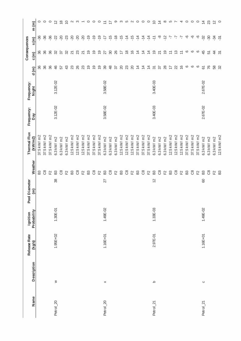
Nam
e D
escr
iptio
n R
elea
se R
ate
(kg/
s)
Igni
tion
Prob
abili
ty
Pool
Dia
met
er
(m)
Wea
ther
Th
erm
al F
lux
(kW
/m2)
Fr
eque
ncy:
D
ay
Freq
uenc
y:
Nig
ht
Con
sequ
ence
s
d (m
) c
(m)
s (m
) m
(m)
B3
37.5
kW
/m2
36
36
-36
0 C
8 37
.5 k
W/m
2 36
36
-3
6 0
F2
37.5
kW
/m2
36
36
-36
0 Pe
trol
_20
w
1.95
E+02
1.
30E-
01
38
B3
6.3
kW/m
2 3.
12E-
02
3.12
E-02
46
32
-2
2 12
C
8 6.
3 kW
/m2
57
37
-20
18
F2
6.3
kW/m
2 43
32
-2
3 10
B3
12
.5 k
W/m
2 23
21
-2
0 2
C8
12.5
kW
/m2
26
23
-20
3 F2
12
.5 k
W/m
2 23
21
-2
0 1
B3
37.5
kW
/m2
19
19
-19
0 C
8 37
.5 k
W/m
2 19
19
-1
9 0
F2
37.5
kW
/m2
19
19
-19
0 Pe
trol
_20
x 1.
16E+
01
1.49
E-02
27
B3
6.
3 kW
/m2
3.58
E-02
3.
58E-
02
39
27
-17
11
C8
6.3
kW/m
2 48
30
-1
5 17
F2
6.
3 kW
/m2
37
26
-18
9 B3
12
.5 k
W/m
2 20
17
-1
5 3
C8
12.5
kW
/m2
23
18
-14
5 F2
12
.5 k
W/m
2 20
16
-1
5 2
B3
37.5
kW
/m2
14
14
-14
0 C
8 37
.5 k
W/m
2 14
14
-1
4 0
F2
37.5
kW
/m2
14
14
-14
0 Pe
trol
_21
b 2.
97E-
01
1.33
E-03
12
B3
6.
3 kW
/m2
3.40
E-03
3.
40E-
03
31
19
-11
10
C8
6.3
kW/m
2 37
21
-8
14
F2
6.
3 kW
/m2
28
19
-12
8 B3
12
.5 k
W/m
2 17
11
-7
5
C8
12.5
kW
/m2
22
13
-7
7 F2
12
.5 k
W/m
2 16
11
-7
4
B3
37.5
kW
/m2
6 6
-6
0 C
8 37
.5 k
W/m
2 6
6 -6
0
F2
37.5
kW
/m2
6 6
-6
0 Pe
trol
_21
c 1.
16E+
01
1.49
E-02
60
B3
6.
3 kW
/m2
2.67
E-02
2.
67E-
02
61
45
-32
14
C8
6.3
kW/m
2 76
51
-3
0 23
F2
6.
3 kW
/m2
58
44
-34
12
B3
12.5
kW
/m2
32
31
-31
0

Nam
e D
escr
iptio
n R
elea
se R
ate
(kg/
s)
Igni
tion
Prob
abili
ty
Pool
Dia
met
er
(m)
Wea
ther
Th
erm
al F
lux
(kW
/m2)
Fr
eque
ncy:
D
ay
Freq
uenc
y:
Nig
ht
Con
sequ
ence
s
d (m
) c
(m)
s (m
) m
(m)
C8
12.5
kW
/m2
33
32
-30
1 F2
12
.5 k
W/m
2 31
31
-3
1 0
B3
37.5
kW
/m2
30
30
-30
0 C
8 37
.5 k
W/m
2 30
30
-3
0 0
F2
37.5
kW
/m2
30
30
-30
0 Pe
trol
_21
d 1.
29E+
02
1.30
E-01
10
0 B3
6.
3 kW
/m2
1.33
E-01
1.
33E-
01
91
70
-54
19
C8
6.3
kW/m
2 11
3 80
-5
0 32
F2
6.
3 kW
/m2
87
69
-56
15
B3
12.5
kW
/m2
51
51
-51
0 C
8 12
.5 k
W/m
2 53
52
-5
0 2
F2
12.5
kW
/m2
51
51
-50
0 B3
37
.5 k
W/m
2 50
50
-5
0 0
C8
37.5
kW
/m2
50
50
-50
0 F2
37
.5 k
W/m
2 50
50
-5
0 0
Petr
ol_2
1 e
1.16
E+03
1.
30E-
01
100
B3
6.3
kW/m
2 6.
66E-
02
6.66
E-02
91
70
-5
4 19
C
8 6.
3 kW
/m2
113
80
-50
32
F2
6.3
kW/m
2 87
69
-5
6 15
B3
12
.5 k
W/m
2 51
51
-5
1 0
C8
12.5
kW
/m2
53
52
-50
2 F2
12
.5 k
W/m
2 51
51
-5
0 0
B3
37.5
kW
/m2
50
50
-50
0 C
8 37
.5 k
W/m
2 50
50
-5
0 0
F2
37.5
kW
/m2
50
50
-50
0 Pe
trol
_21
f 3.
14E+
00
5.00
E-03
34
B3
6.
3 kW
/m2
1.17
E-03
1.
17E-
03
43
30
-20
12
C8
6.3
kW/m
2 53
34
-1
8 18
F2
6.
3 kW
/m2
40
29
-21
10
B3
12.5
kW
/m2
22
19
-18
2 C
8 12
.5 k
W/m
2 25
21
-1
7 4
F2
12.5
kW
/m2
22
19
-18
2 B3
37
.5 k
W/m
2 17
17
-1
7 0
C8
37.5
kW
/m2
17
17
-17
0 F2
37
.5 k
W/m
2 17
17
-1
7 0
Petr
ol_2
1 v
3.14
E+00
5.
00E-
03
34
B3
6.3
kW/m
2 1.
93E-
03
1.93
E-03
43
30
-2
0 12
C
8 6.
3 kW
/m2
53
34
-18
18

Nam
e D
escr
iptio
n R
elea
se R
ate
(kg/
s)
Igni
tion
Prob
abili
ty
Pool
Dia
met
er
(m)
Wea
ther
Th
erm
al F
lux
(kW
/m2)
Fr
eque
ncy:
D
ay
Freq
uenc
y:
Nig
ht
Con
sequ
ence
s
d (m
) c
(m)
s (m
) m
(m)
F2
6.3
kW/m
2 40
29
-2
1 10
B3
12
.5 k
W/m
2 22
19
-1
8 2
C8
12.5
kW
/m2
25
21
-17
4 F2
12
.5 k
W/m
2 22
19
-1
8 2
B3
37.5
kW
/m2
17
17
-17
0 C
8 37
.5 k
W/m
2 17
17
-1
7 0
F2
37.5
kW
/m2
17
17
-17
0 Pe
trol
_22
S N
/A
1.00
E+00
34
B3
6.
3 kW
/m2
4.50
E+01
4.
50E+
01
43
30
-20
12
C8
6.3
kW/m
2 54
34
-1
8 18
F2
6.
3 kW
/m2
41
30
-22
10
B3
12.5
kW
/m2
22
19
-18
2 C
8 12
.5 k
W/m
2 25
21
-1
8 4
F2
12.5
kW
/m2
22
19
-18
2 B3
37
.5 k
W/m
2 17
17
-1
7 0
C8
37.5
kW
/m2
17
17
-17
0 F2
37
.5 k
W/m
2 17
17
-1
7 0
Petr
ol_2
2 L
N/A
1.
00E+
00
69
B3
6.3
kW/m
2 3.
00E+
01
3.00
E+01
67
50
-3
7 15
C
8 6.
3 kW
/m2
84
57
-34
25
F2
6.3
kW/m
2 64
49
-3
9 12
B3
12
.5 k
W/m
2 35
35
-3
5 0
C8
12.5
kW
/m2
37
36
-35
1 F2
12
.5 k
W/m
2 35
35
-3
5 0
B3
37.5
kW
/m2
34
34
-34
0 C
8 37
.5 k
W/m
2 34
34
-3
4 0
F2
37.5
kW
/m2
34
34
-34
0 Pe
trol
_22
C
N/A
1.
50E-
02
121
B3
6.3
kW/m
2 3.
75E-
02
3.75
E-02
10
8 83
-6
5 21
C
8 6.
3 kW
/m2
134
95
-61
37
F2
6.3
kW/m
2 10
3 82
-6
9 17
B3
12
.5 k
W/m
2 62
62
-6
1 0
C8
12.5
kW
/m2
65
63
-61
2 F2
12
.5 k
W/m
2 62
62
-6
1 0
B3
37.5
kW
/m2
61
61
-61
0 C
8 37
.5 k
W/m
2 61
61
-6
1 0
F2
37.5
kW
/m2
61
61
-61
0

Nam
e D
escr
iptio
n R
elea
se R
ate
(kg/
s)
Igni
tion
Prob
abili
ty
Pool
Dia
met
er
(m)
Wea
ther
Th
erm
al F
lux
(kW
/m2)
Fr
eque
ncy:
D
ay
Freq
uenc
y:
Nig
ht
Con
sequ
ence
s
d (m
) c
(m)
s (m
) m
(m)
Petr
ol_2
3 S
N/A
1.
00E+
00
39
B3
6.3
kW/m
2 4.
50E+
01
4.50
E+01
46
33
-2
2 12
C
8 6.
3 kW
/m2
58
37
-20
19
F2
6.3
kW/m
2 44
32
-2
4 10
B3
12
.5 k
W/m
2 24
22
-2
1 2
C8
12.5
kW
/m2
26
23
-20
3 F2
12
.5 k
W/m
2 23
22
-2
1 1
B3
37.5
kW
/m2
20
20
-20
0 C
8 37
.5 k
W/m
2 20
20
-2
0 0
F2
37.5
kW
/m2
20
20
-20
0 Pe
trol
_23
L N
/A
1.00
E+00
79
B3
6.
3 kW
/m2
3.00
E+01
3.
00E+
01
74
56
-42
16
C8
6.3
kW/m
2 93
64
-3
9 27
F2
6.
3 kW
/m2
71
55
-44
13
B3
12.5
kW
/m2
40
40
-40
0 C
8 12
.5 k
W/m
2 42
41
-4
0 1
F2
12.5
kW
/m2
40
40
-40
0 B3
37
.5 k
W/m
2 39
39
-3
9 0
C8
37.5
kW
/m2
39
39
-39
0 F2
37
.5 k
W/m
2 39
39
-3
9 0
Petr
ol_2
3 C
N
/A
1.50
E-02
12
7 B3
6.
3 kW
/m2
3.75
E-02
3.
75E-
02
112
87
-69
22
C8
6.3
kW/m
2 13
9 10
0 -6
4 38
F2
6.
3 kW
/m2
108
86
-72
18
B3
12.5
kW
/m2
66
65
-64
1 C
8 12
.5 k
W/m
2 69
66
-6
4 3
F2
12.5
kW
/m2
65
65
-64
1 B3
37
.5 k
W/m
2 64
64
-6
4 0
C8
37.5
kW
/m2
64
64
-64
0 F2
37
.5 k
W/m
2 64
64
-6
4 0
Petr
ol_2
4 S
N/A
1.
00E+
00
34
B3
6.3
kW/m
2 4.
50E+
01
4.50
E+01
43
30
-2
0 12
C
8 6.
3 kW
/m2
53
34
-18
18
F2
6.3
kW/m
2 40
29
-2
1 10
B3
12
.5 k
W/m
2 22
19
-1
8 2
C8
12.5
kW
/m2
25
21
-18
4 F2
12
.5 k
W/m
2 22
19
-1
8 2
B3
37.5
kW
/m2
17
17
-17
0

Nam
e D
escr
iptio
n R
elea
se R
ate
(kg/
s)
Igni
tion
Prob
abili
ty
Pool
Dia
met
er
(m)
Wea
ther
Th
erm
al F
lux
(kW
/m2)
Fr
eque
ncy:
D
ay
Freq
uenc
y:
Nig
ht
Con
sequ
ence
s
d (m
) c
(m)
s (m
) m
(m)
C8
37.5
kW
/m2
17
17
-17
0 F2
37
.5 k
W/m
2 17
17
-1
7 0
Petr
ol_2
4 L
N/A
1.
00E+
00
68
B3
6.3
kW/m
2 3.
00E+
01
3.00
E+01
66
49
-3
6 15
C
8 6.
3 kW
/m2
82
56
-34
24
F2
6.3
kW/m
2 63
48
-3
8 12
B3
12
.5 k
W/m
2 35
34
-3
4 0
C8
12.5
kW
/m2
36
36
-34
1 F2
12
.5 k
W/m
2 35
34
-3
4 0
B3
37.5
kW
/m2
34
34
-34
0 C
8 37
.5 k
W/m
2 34
34
-3
4 0
F2
37.5
kW
/m2
34
34
-34
0 Pe
trol
_24
C
N/A
1.
50E-
02
121
B3
6.3
kW/m
2 3.
75E-
02
3.75
E-02
10
7 83
-6
5 21
C
8 6.
3 kW
/m2
133
95
-60
36
F2
6.3
kW/m
2 10
3 82
-6
8 17
B3
12
.5 k
W/m
2 62
61
-6
1 0
C8
12.5
kW
/m2
65
62
-60
2 F2
12
.5 k
W/m
2 62
61
-6
1 0
B3
37.5
kW
/m2
60
60
-60
0 C
8 37
.5 k
W/m
2 60
60
-6
0 0
F2
37.5
kW
/m2
60
60
-60
0 Pe
trol
_25
b 2.
66E-
01
1.28
E-03
11
B3
6.
3 kW
/m2
2.55
E-01
2.
55E-
01
31
19
-11
10
C8
6.3
kW/m
2 37
21
-8
14
F2
6.
3 kW
/m2
28
19
-12
8 B3
12
.5 k
W/m
2 17
11
-7
5
C8
12.5
kW
/m2
22
13
-7
8 F2
12
.5 k
W/m
2 16
10
-7
4
B3
37.5
kW
/m2
6 6
-6
0 C
8 37
.5 k
W/m
2 6
6 -6
0
F2
37.5
kW
/m2
6 6
-6
0 Pe
trol
_25
c 1.
04E+
01
1.35
E-02
57
B3
6.
3 kW
/m2
1.89
E+00
1.
89E+
00
59
43
-31
14
C8
6.3
kW/m
2 73
49
-2
9 22
F2
6.
3 kW
/m2
56
42
-33
11
B3
12.5
kW
/m2
30
29
-29
1 C
8 12
.5 k
W/m
2 32
31
-2
9 2

Nam
e D
escr
iptio
n R
elea
se R
ate
(kg/
s)
Igni
tion
Prob
abili
ty
Pool
Dia
met
er
(m)
Wea
ther
Th
erm
al F
lux
(kW
/m2)
Fr
eque
ncy:
D
ay
Freq
uenc
y:
Nig
ht
Con
sequ
ence
s
d (m
) c
(m)
s (m
) m
(m)
F2
12.5
kW
/m2
30
30
-29
0 B3
37
.5 k
W/m
2 29
29
-2
9 0
C8
37.5
kW
/m2
29
29
-29
0 F2
37
.5 k
W/m
2 29
29
-2
9 0
Petr
ol_2
5 d
7.50
E+01
8.
91E-
02
100
B3
6.3
kW/m
2 7.
13E+
00
7.13
E+00
91
70
-5
4 19
C
8 6.
3 kW
/m2
113
80
-50
32
F2
6.3
kW/m
2 87
69
-5
6 15
B3
12
.5 k
W/m
2 51
51
-5
1 0
C8
12.5
kW
/m2
53
52
-50
2 F2
12
.5 k
W/m
2 51
51
-5
0 0
B3
37.5
kW
/m2
50
50
-50
0 C
8 37
.5 k
W/m
2 50
50
-5
0 0
F2
37.5
kW
/m2
50
50
-50
0 Pe
trol
_25
e 7.
50E+
01
8.91
E-02
10
0 B3
6.
3 kW
/m2
3.56
E+00
3.
56E+
00
91
70
-54
19
C8
6.3
kW/m
2 11
3 80
-5
0 32
F2
6.
3 kW
/m2
87
69
-56
15
B3
12.5
kW
/m2
51
51
-51
0 C
8 12
.5 k
W/m
2 53
52
-5
0 2
F2
12.5
kW
/m2
51
51
-50
0 B3
37
.5 k
W/m
2 50
50
-5
0 0
C8
37.5
kW
/m2
50
50
-50
0 F2
37
.5 k
W/m
2 50
50
-5
0 0
Petr
ol_2
5 f
2.80
E+00
4.
61E-
03
32
B3
6.3
kW/m
2 8.
40E-
02
8.40
E-02
42
29
-1
9 12
C
8 6.
3 kW
/m2
52
33
-17
17
F2
6.3
kW/m
2 39
29
-2
0 9
B3
12.5
kW
/m2
22
19
-17
2 C
8 12
.5 k
W/m
2 24
20
-1
7 4
F2
12.5
kW
/m2
21
18
-17
2 B3
37
.5 k
W/m
2 16
16
-1
6 0
C8
37.5
kW
/m2
16
16
-16
0 F2
37
.5 k
W/m
2 16
16
-1
6 0
Petr
ol_2
5 v
2.80
E+00
4.
61E-
03
32
B3
6.3
kW/m
2 1.
28E-
01
1.28
E-01
42
29
-1
9 12
C
8 6.
3 kW
/m2
52
33
-17
17
F2
6.3
kW/m
2 39
29
-2
0 9
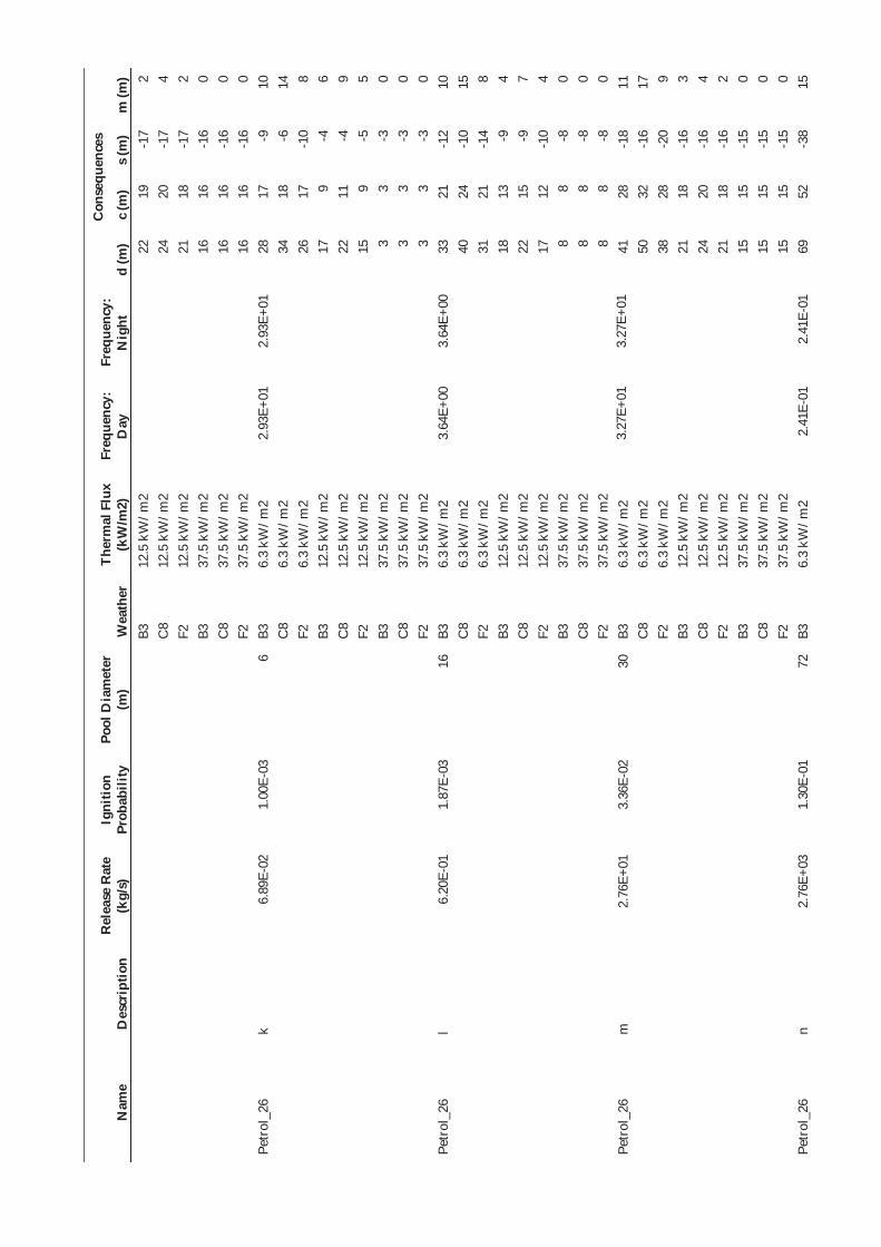
Nam
e D
escr
iptio
n R
elea
se R
ate
(kg/
s)
Igni
tion
Prob
abili
ty
Pool
Dia
met
er
(m)
Wea
ther
Th
erm
al F
lux
(kW
/m2)
Fr
eque
ncy:
D
ay
Freq
uenc
y:
Nig
ht
Con
sequ
ence
s
d (m
) c
(m)
s (m
) m
(m)
B3
12.5
kW
/m2
22
19
-17
2 C
8 12
.5 k
W/m
2 24
20
-1
7 4
F2
12.5
kW
/m2
21
18
-17
2 B3
37
.5 k
W/m
2 16
16
-1
6 0
C8
37.5
kW
/m2
16
16
-16
0 F2
37
.5 k
W/m
2 16
16
-1
6 0
Petr
ol_2
6 k
6.89
E-02
1.
00E-
03
6 B3
6.
3 kW
/m2
2.93
E+01
2.
93E+
01
28
17
-9
10
C8
6.3
kW/m
2 34
18
-6
14
F2
6.
3 kW
/m2
26
17
-10
8 B3
12
.5 k
W/m
2 17
9
-4
6 C
8 12
.5 k
W/m
2 22
11
-4
9
F2
12.5
kW
/m2
15
9 -5
5
B3
37.5
kW
/m2
3 3
-3
0 C
8 37
.5 k
W/m
2 3
3 -3
0
F2
37.5
kW
/m2
3 3
-3
0 Pe
trol
_26
l 6.
20E-
01
1.87
E-03
16
B3
6.
3 kW
/m2
3.64
E+00
3.
64E+
00
33
21
-12
10
C8
6.3
kW/m
2 40
24
-1
0 15
F2
6.
3 kW
/m2
31
21
-14
8 B3
12
.5 k
W/m
2 18
13
-9
4
C8
12.5
kW
/m2
22
15
-9
7 F2
12
.5 k
W/m
2 17
12
-1
0 4
B3
37.5
kW
/m2
8 8
-8
0 C
8 37
.5 k
W/m
2 8
8 -8
0
F2
37.5
kW
/m2
8 8
-8
0 Pe
trol
_26
m
2.76
E+01
3.
36E-
02
30
B3
6.3
kW/m
2 3.
27E+
01
3.27
E+01
41
28
-1
8 11
C
8 6.
3 kW
/m2
50
32
-16
17
F2
6.3
kW/m
2 38
28
-2
0 9
B3
12.5
kW
/m2
21
18
-16
3 C
8 12
.5 k
W/m
2 24
20
-1
6 4
F2
12.5
kW
/m2
21
18
-16
2 B3
37
.5 k
W/m
2 15
15
-1
5 0
C8
37.5
kW
/m2
15
15
-15
0 F2
37
.5 k
W/m
2 15
15
-1
5 0
Petr
ol_2
6 n
2.76
E+03
1.
30E-
01
72
B3
6.3
kW/m
2 2.
41E-
01
2.41
E-01
69
52
-3
8 15

Nam
e D
escr
iptio
n R
elea
se R
ate
(kg/
s)
Igni
tion
Prob
abili
ty
Pool
Dia
met
er
(m)
Wea
ther
Th
erm
al F
lux
(kW
/m2)
Fr
eque
ncy:
D
ay
Freq
uenc
y:
Nig
ht
Con
sequ
ence
s
d (m
) c
(m)
s (m
) m
(m)
C8
6.3
kW/m
2 87
60
-3
6 25
F2
6.
3 kW
/m2
66
51
-41
13
B3
12.5
kW
/m2
37
37
-37
0 C
8 12
.5 k
W/m
2 39
38
-3
6 1
F2
12.5
kW
/m2
37
37
-37
0 B3
37
.5 k
W/m
2 36
36
-3
6 0
C8
37.5
kW
/m2
36
36
-36
0 F2
37
.5 k
W/m
2 36
36
-3
6 0
Petr
ol_2
7 b
2.66
E-01
1.
04E-
03
11
B3
6.3
kW/m
2 2.
07E-
02
2.07
E-02
31
19
-1
1 10
C
8 6.
3 kW
/m2
37
21
-8
14
F2
6.3
kW/m
2 28
19
-1
2 8
B3
12.5
kW
/m2
17
11
-7
5 C
8 12
.5 k
W/m
2 22
13
-7
8
F2
12.5
kW
/m2
16
10
-7
4 B3
37
.5 k
W/m
2 6
6 -6
0
C8
37.5
kW
/m2
6 6
-6
0 F2
37
.5 k
W/m
2 6
6 -6
0
Petr
ol_2
7 c
1.04
E+01
3.
78E-
03
28
B3
6.3
kW/m
2 4.
72E-
02
4.72
E-02
40
27
-1
7 11
C
8 6.
3 kW
/m2
49
30
-15
17
F2
6.3
kW/m
2 37
27
-1
9 9
B3
12.5
kW
/m2
21
17
-15
3 C
8 12
.5 k
W/m
2 24
19
-1
5 4
F2
12.5
kW
/m2
20
17
-15
2 B3
37
.5 k
W/m
2 14
14
-1
4 0
C8
37.5
kW
/m2
14
14
-14
0 F2
37
.5 k
W/m
2 14
14
-1
4 0
Petr
ol_2
7 d
7.50
E+01
1.
50E-
02
28
B3
6.3
kW/m
2 7.
50E-
02
7.50
E-02
40
27
-1
7 11
C
8 6.
3 kW
/m2
49
30
-15
17
F2
6.3
kW/m
2 37
27
-1
9 9
B3
12.5
kW
/m2
21
17
-15
3 C
8 12
.5 k
W/m
2 24
19
-1
5 4
F2
12.5
kW
/m2
20
17
-15
2 B3
37
.5 k
W/m
2 14
14
-1
4 0
C8
37.5
kW
/m2
14
14
-14
0
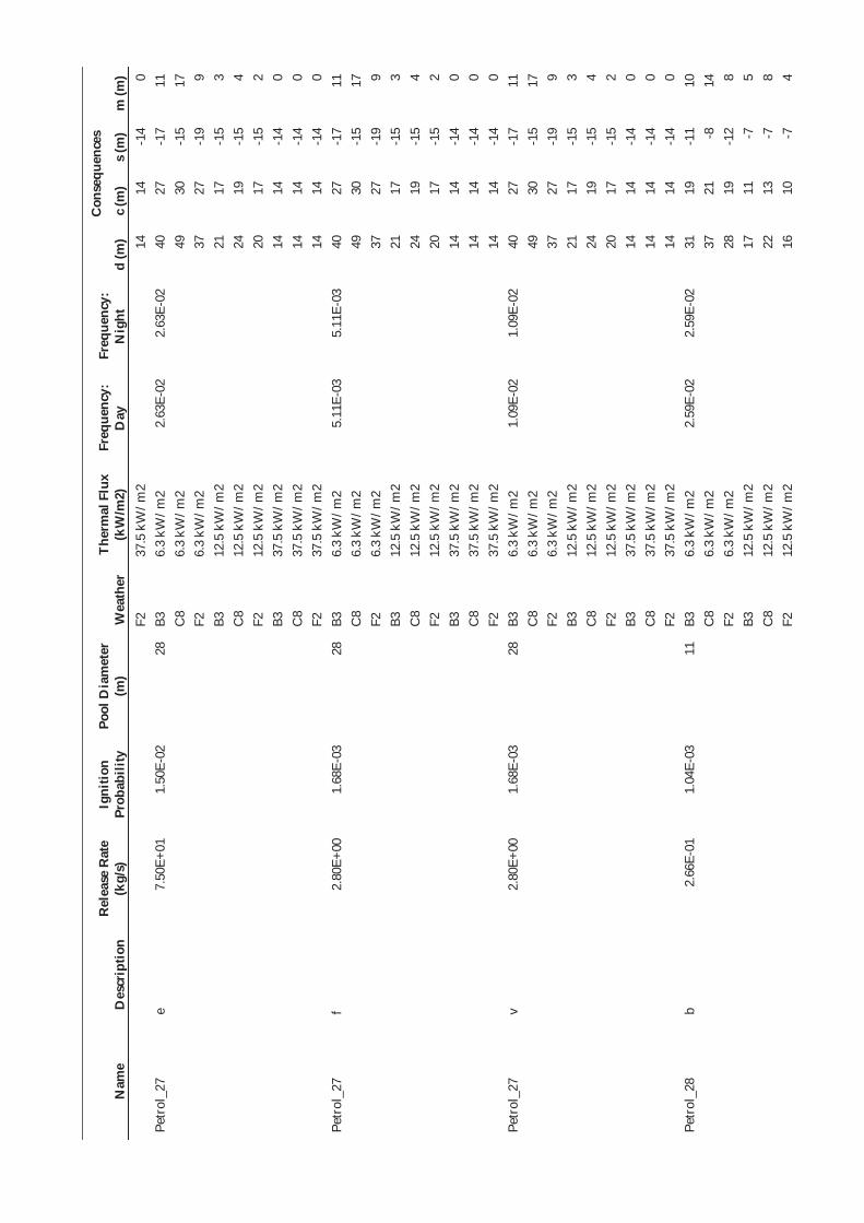
Nam
e D
escr
iptio
n R
elea
se R
ate
(kg/
s)
Igni
tion
Prob
abili
ty
Pool
Dia
met
er
(m)
Wea
ther
Th
erm
al F
lux
(kW
/m2)
Fr
eque
ncy:
D
ay
Freq
uenc
y:
Nig
ht
Con
sequ
ence
s
d (m
) c
(m)
s (m
) m
(m)
F2
37.5
kW
/m2
14
14
-14
0 Pe
trol
_27
e 7.
50E+
01
1.50
E-02
28
B3
6.
3 kW
/m2
2.63
E-02
2.
63E-
02
40
27
-17
11
C8
6.3
kW/m
2 49
30
-1
5 17
F2
6.
3 kW
/m2
37
27
-19
9 B3
12
.5 k
W/m
2 21
17
-1
5 3
C8
12.5
kW
/m2
24
19
-15
4 F2
12
.5 k
W/m
2 20
17
-1
5 2
B3
37.5
kW
/m2
14
14
-14
0 C
8 37
.5 k
W/m
2 14
14
-1
4 0
F2
37.5
kW
/m2
14
14
-14
0 Pe
trol
_27
f 2.
80E+
00
1.68
E-03
28
B3
6.
3 kW
/m2
5.11
E-03
5.
11E-
03
40
27
-17
11
C8
6.3
kW/m
2 49
30
-1
5 17
F2
6.
3 kW
/m2
37
27
-19
9 B3
12
.5 k
W/m
2 21
17
-1
5 3
C8
12.5
kW
/m2
24
19
-15
4 F2
12
.5 k
W/m
2 20
17
-1
5 2
B3
37.5
kW
/m2
14
14
-14
0 C
8 37
.5 k
W/m
2 14
14
-1
4 0
F2
37.5
kW
/m2
14
14
-14
0 Pe
trol
_27
v 2.
80E+
00
1.68
E-03
28
B3
6.
3 kW
/m2
1.09
E-02
1.
09E-
02
40
27
-17
11
C8
6.3
kW/m
2 49
30
-1
5 17
F2
6.
3 kW
/m2
37
27
-19
9 B3
12
.5 k
W/m
2 21
17
-1
5 3
C8
12.5
kW
/m2
24
19
-15
4 F2
12
.5 k
W/m
2 20
17
-1
5 2
B3
37.5
kW
/m2
14
14
-14
0 C
8 37
.5 k
W/m
2 14
14
-1
4 0
F2
37.5
kW
/m2
14
14
-14
0 Pe
trol
_28
b 2.
66E-
01
1.04
E-03
11
B3
6.
3 kW
/m2
2.59
E-02
2.
59E-
02
31
19
-11
10
C8
6.3
kW/m
2 37
21
-8
14
F2
6.
3 kW
/m2
28
19
-12
8 B3
12
.5 k
W/m
2 17
11
-7
5
C8
12.5
kW
/m2
22
13
-7
8 F2
12
.5 k
W/m
2 16
10
-7
4
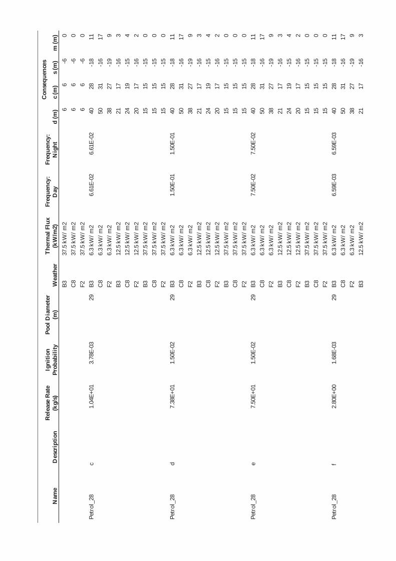
Nam
e D
escr
iptio
n R
elea
se R
ate
(kg/
s)
Igni
tion
Prob
abili
ty
Pool
Dia
met
er
(m)
Wea
ther
Th
erm
al F
lux
(kW
/m2)
Fr
eque
ncy:
D
ay
Freq
uenc
y:
Nig
ht
Con
sequ
ence
s
d (m
) c
(m)
s (m
) m
(m)
B3
37.5
kW
/m2
6 6
-6
0 C
8 37
.5 k
W/m
2 6
6 -6
0
F2
37.5
kW
/m2
6 6
-6
0 Pe
trol
_28
c 1.
04E+
01
3.78
E-03
29
B3
6.
3 kW
/m2
6.61
E-02
6.
61E-
02
40
28
-18
11
C8
6.3
kW/m
2 50
31
-1
6 17
F2
6.
3 kW
/m2
38
27
-19
9 B3
12
.5 k
W/m
2 21
17
-1
6 3
C8
12.5
kW
/m2
24
19
-15
4 F2
12
.5 k
W/m
2 20
17
-1
6 2
B3
37.5
kW
/m2
15
15
-15
0 C
8 37
.5 k
W/m
2 15
15
-1
5 0
F2
37.5
kW
/m2
15
15
-15
0 Pe
trol
_28
d 7.
38E+
01
1.50
E-02
29
B3
6.
3 kW
/m2
1.50
E-01
1.
50E-
01
40
28
-18
11
C8
6.3
kW/m
2 50
31
-1
6 17
F2
6.
3 kW
/m2
38
27
-19
9 B3
12
.5 k
W/m
2 21
17
-1
6 3
C8
12.5
kW
/m2
24
19
-15
4 F2
12
.5 k
W/m
2 20
17
-1
6 2
B3
37.5
kW
/m2
15
15
-15
0 C
8 37
.5 k
W/m
2 15
15
-1
5 0
F2
37.5
kW
/m2
15
15
-15
0 Pe
trol
_28
e 7.
50E+
01
1.50
E-02
29
B3
6.
3 kW
/m2
7.50
E-02
7.
50E-
02
40
28
-18
11
C8
6.3
kW/m
2 50
31
-1
6 17
F2
6.
3 kW
/m2
38
27
-19
9 B3
12
.5 k
W/m
2 21
17
-1
6 3
C8
12.5
kW
/m2
24
19
-15
4 F2
12
.5 k
W/m
2 20
17
-1
6 2
B3
37.5
kW
/m2
15
15
-15
0 C
8 37
.5 k
W/m
2 15
15
-1
5 0
F2
37.5
kW
/m2
15
15
-15
0 Pe
trol
_28
f 2.
80E+
00
1.68
E-03
29
B3
6.
3 kW
/m2
6.59
E-03
6.
59E-
03
40
28
-18
11
C8
6.3
kW/m
2 50
31
-1
6 17
F2
6.
3 kW
/m2
38
27
-19
9 B3
12
.5 k
W/m
2 21
17
-1
6 3
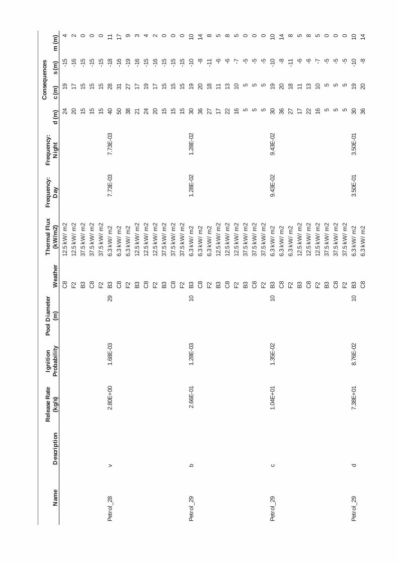
Nam
e D
escr
iptio
n R
elea
se R
ate
(kg/
s)
Igni
tion
Prob
abili
ty
Pool
Dia
met
er
(m)
Wea
ther
Th
erm
al F
lux
(kW
/m2)
Fr
eque
ncy:
D
ay
Freq
uenc
y:
Nig
ht
Con
sequ
ence
s
d (m
) c
(m)
s (m
) m
(m)
C8
12.5
kW
/m2
24
19
-15
4 F2
12
.5 k
W/m
2 20
17
-1
6 2
B3
37.5
kW
/m2
15
15
-15
0 C
8 37
.5 k
W/m
2 15
15
-1
5 0
F2
37.5
kW
/m2
15
15
-15
0 Pe
trol
_28
v 2.
80E+
00
1.68
E-03
29
B3
6.
3 kW
/m2
7.73
E-03
7.
73E-
03
40
28
-18
11
C8
6.3
kW/m
2 50
31
-1
6 17
F2
6.
3 kW
/m2
38
27
-19
9 B3
12
.5 k
W/m
2 21
17
-1
6 3
C8
12.5
kW
/m2
24
19
-15
4 F2
12
.5 k
W/m
2 20
17
-1
6 2
B3
37.5
kW
/m2
15
15
-15
0 C
8 37
.5 k
W/m
2 15
15
-1
5 0
F2
37.5
kW
/m2
15
15
-15
0 Pe
trol
_29
b 2.
66E-
01
1.28
E-03
10
B3
6.
3 kW
/m2
1.28
E-02
1.
28E-
02
30
19
-10
10
C8
6.3
kW/m
2 36
20
-8
14
F2
6.
3 kW
/m2
27
18
-11
8 B3
12
.5 k
W/m
2 17
11
-6
5
C8
12.5
kW
/m2
22
13
-6
8 F2
12
.5 k
W/m
2 16
10
-7
5
B3
37.5
kW
/m2
5 5
-5
0 C
8 37
.5 k
W/m
2 5
5 -5
0
F2
37.5
kW
/m2
5 5
-5
0 Pe
trol
_29
c 1.
04E+
01
1.35
E-02
10
B3
6.
3 kW
/m2
9.43
E-02
9.
43E-
02
30
19
-10
10
C8
6.3
kW/m
2 36
20
-8
14
F2
6.
3 kW
/m2
27
18
-11
8 B3
12
.5 k
W/m
2 17
11
-6
5
C8
12.5
kW
/m2
22
13
-6
8 F2
12
.5 k
W/m
2 16
10
-7
5
B3
37.5
kW
/m2
5 5
-5
0 C
8 37
.5 k
W/m
2 5
5 -5
0
F2
37.5
kW
/m2
5 5
-5
0 Pe
trol
_29
d 7.
38E+
01
8.76
E-02
10
B3
6.
3 kW
/m2
3.50
E-01
3.
50E-
01
30
19
-10
10
C8
6.3
kW/m
2 36
20
-8
14

Nam
e D
escr
iptio
n R
elea
se R
ate
(kg/
s)
Igni
tion
Prob
abili
ty
Pool
Dia
met
er
(m)
Wea
ther
Th
erm
al F
lux
(kW
/m2)
Fr
eque
ncy:
D
ay
Freq
uenc
y:
Nig
ht
Con
sequ
ence
s
d (m
) c
(m)
s (m
) m
(m)
F2
6.3
kW/m
2 27
18
-1
1 8
B3
12.5
kW
/m2
17
11
-6
5 C
8 12
.5 k
W/m
2 22
13
-6
8
F2
12.5
kW
/m2
16
10
-7
5 B3
37
.5 k
W/m
2 5
5 -5
0
C8
37.5
kW
/m2
5 5
-5
0 F2
37
.5 k
W/m
2 5
5 -5
0
Petr
ol_2
9 e
7.50
E+01
8.
91E-
02
10
B3
6.3
kW/m
2 1.
78E-
01
1.78
E-01
30
19
-1
0 10
C
8 6.
3 kW
/m2
36
20
-8
14
F2
6.3
kW/m
2 27
18
-1
1 8
B3
12.5
kW
/m2
17
11
-6
5 C
8 12
.5 k
W/m
2 22
13
-6
8
F2
12.5
kW
/m2
16
10
-7
5 B3
37
.5 k
W/m
2 5
5 -5
0
C8
37.5
kW
/m2
5 5
-5
0 F2
37
.5 k
W/m
2 5
5 -5
0
Petr
ol_2
9 p
7.50
E+01
8.
91E-
02
10
B3
6.3
kW/m
2 4.
01E+
00
4.01
E+00
30
19
-1
0 10
C
8 6.
3 kW
/m2
36
20
-8
14
F2
6.3
kW/m
2 27
18
-1
1 8
B3
12.5
kW
/m2
17
11
-6
5 C
8 12
.5 k
W/m
2 22
13
-6
8
F2
12.5
kW
/m2
16
10
-7
5 B3
37
.5 k
W/m
2 5
5 -5
0
C8
37.5
kW
/m2
5 5
-5
0 F2
37
.5 k
W/m
2 5
5 -5
0
Petr
ol_2
9 f
2.80
E+00
4.
61E-
03
10
B3
6.3
kW/m
2 8.
03E-
03
8.03
E-03
30
19
-1
0 10
C
8 6.
3 kW
/m2
36
20
-8
14
F2
6.3
kW/m
2 27
18
-1
1 8
B3
12.5
kW
/m2
17
11
-6
5 C
8 12
.5 k
W/m
2 22
13
-6
8
F2
12.5
kW
/m2
16
10
-7
5 B3
37
.5 k
W/m
2 5
5 -5
0
C8
37.5
kW
/m2
5 5
-5
0 F2
37
.5 k
W/m
2 5
5 -5
0

Nam
e D
escr
iptio
n R
elea
se R
ate
(kg/
s)
Igni
tion
Prob
abili
ty
Pool
Dia
met
er
(m)
Wea
ther
Th
erm
al F
lux
(kW
/m2)
Fr
eque
ncy:
D
ay
Freq
uenc
y:
Nig
ht
Con
sequ
ence
s
d (m
) c
(m)
s (m
) m
(m)
Petr
ol_2
9 v
2.80
E+00
4.
61E-
03
10
B3
6.3
kW/m
2 1.
06E-
02
1.06
E-02
30
19
-1
0 10
C
8 6.
3 kW
/m2
36
20
-8
14
F2
6.3
kW/m
2 27
18
-1
1 8
B3
12.5
kW
/m2
17
11
-6
5 C
8 12
.5 k
W/m
2 22
13
-6
8
F2
12.5
kW
/m2
16
10
-7
5 B3
37
.5 k
W/m
2 5
5 -5
0
C8
37.5
kW
/m2
5 5
-5
0 F2
37
.5 k
W/m
2 5
5 -5
0
Etha
nol_
30
k 4.
21E-
01
1.53
E-03
7
B3
6.3
kW/m
2 1.
50E+
00
1.50
E+00
28
17
-9
10
C
8 6.
3 kW
/m2
34
18
-6
14
F2
6.3
kW/m
2 26
17
-1
0 8
B3
12.5
kW
/m2
17
9 -5
6
C8
12.5
kW
/m2
22
12
-5
9 F2
12
.5 k
W/m
2 15
9
-5
5 B3
37
.5 k
W/m
2 3
3 -3
0
C8
37.5
kW
/m2
3 3
-3
0 F2
37
.5 k
W/m
2 3
3 -3
0
Etha
nol_
30
l 3.
79E+
00
5.76
E-03
7
B3
6.3
kW/m
2 3.
74E-
01
3.74
E-01
28
17
-9
10
C
8 6.
3 kW
/m2
34
18
-6
14
F2
6.3
kW/m
2 26
17
-1
0 8
B3
12.5
kW
/m2
17
9 -5
6
C8
12.5
kW
/m2
22
12
-5
9 F2
12
.5 k
W/m
2 15
9
-5
5 B3
37
.5 k
W/m
2 3
3 -3
0
C8
37.5
kW
/m2
3 3
-3
0 F2
37
.5 k
W/m
2 3
3 -3
0
Etha
nol_
30
m
1.00
E+01
1.
30E-
02
7 B3
6.
3 kW
/m2
8.47
E+00
8.
47E+
00
28
17
-9
10
C8
6.3
kW/m
2 34
18
-6
14
F2
6.
3 kW
/m2
26
17
-10
8 B3
12
.5 k
W/m
2 17
9
-5
6 C
8 12
.5 k
W/m
2 22
12
-5
9
F2
12.5
kW
/m2
15
9 -5
5
B3
37.5
kW
/m2
3 3
-3
0

Nam
e D
escr
iptio
n R
elea
se R
ate
(kg/
s)
Igni
tion
Prob
abili
ty
Pool
Dia
met
er
(m)
Wea
ther
Th
erm
al F
lux
(kW
/m2)
Fr
eque
ncy:
D
ay
Freq
uenc
y:
Nig
ht
Con
sequ
ence
s
d (m
) c
(m)
s (m
) m
(m)
C8
37.5
kW
/m2
3 3
-3
0 F2
37
.5 k
W/m
2 3
3 -3
0
Etha
nol_
30
n 1.
00E+
01
1.30
E-02
56
B3
6.
3 kW
/m2
1.61
E-03
1.
61E-
03
58
43
-30
14
C8
6.3
kW/m
2 72
49
-2
8 22
F2
6.
3 kW
/m2
55
42
-32
11
B3
12.5
kW
/m2
30
29
-29
1 C
8 12
.5 k
W/m
2 32
31
-2
9 2
F2
12.5
kW
/m2
30
29
-29
0 B3
37
.5 k
W/m
2 28
28
-2
8 0
C8
37.5
kW
/m2
28
28
-28
0 F2
37
.5 k
W/m
2 28
28
-2
8 0
Etha
nol_
31
b 2.
66E-
01
1.04
E-03
10
B3
6.
3 kW
/m2
0.00
E+00
0.
00E+
00
30
19
-10
10
C8
6.3
kW/m
2 36
20
-8
14
F2
6.
3 kW
/m2
27
18
-11
8 B3
12
.5 k
W/m
2 17
11
-6
5
C8
12.5
kW
/m2
22
13
-6
8 F2
12
.5 k
W/m
2 16
10
-7
5
B3
37.5
kW
/m2
5 5
-5
0 C
8 37
.5 k
W/m
2 5
5 -5
0
F2
37.5
kW
/m2
5 5
-5
0 Et
hano
l_31
c
1.00
E+01
3.
67E-
03
10
B3
6.3
kW/m
2 3.
67E-
02
3.67
E-02
30
19
-1
0 10
C
8 6.
3 kW
/m2
36
20
-8
14
F2
6.3
kW/m
2 27
18
-1
1 8
B3
12.5
kW
/m2
17
11
-6
5 C
8 12
.5 k
W/m
2 22
13
-6
8
F2
12.5
kW
/m2
16
10
-7
5 B3
37
.5 k
W/m
2 5
5 -5
0
C8
37.5
kW
/m2
5 5
-5
0 F2
37
.5 k
W/m
2 5
5 -5
0
Etha
nol_
31
d 4.
61E+
00
2.16
E-03
10
B3
6.
3 kW
/m2
0.00
E+00
0.
00E+
00
30
19
-10
10
C8
6.3
kW/m
2 36
20
-8
14
F2
6.
3 kW
/m2
27
18
-11
8 B3
12
.5 k
W/m
2 17
11
-6
5
C8
12.5
kW
/m2
22
13
-6
8

Nam
e D
escr
iptio
n R
elea
se R
ate
(kg/
s)
Igni
tion
Prob
abili
ty
Pool
Dia
met
er
(m)
Wea
ther
Th
erm
al F
lux
(kW
/m2)
Fr
eque
ncy:
D
ay
Freq
uenc
y:
Nig
ht
Con
sequ
ence
s
d (m
) c
(m)
s (m
) m
(m)
F2
12.5
kW
/m2
16
10
-7
5 B3
37
.5 k
W/m
2 5
5 -5
0
C8
37.5
kW
/m2
5 5
-5
0 F2
37
.5 k
W/m
2 5
5 -5
0
Etha
nol_
31
e 1.
00E+
01
3.67
E-03
10
B3
6.
3 kW
/m2
1.84
E-02
1.
84E-
02
30
19
-10
10
C8
6.3
kW/m
2 36
20
-8
14
F2
6.
3 kW
/m2
27
18
-11
8 B3
12
.5 k
W/m
2 17
11
-6
5
C8
12.5
kW
/m2
22
13
-6
8 F2
12
.5 k
W/m
2 16
10
-7
5
B3
37.5
kW
/m2
5 5
-5
0 C
8 37
.5 k
W/m
2 5
5 -5
0
F2
37.5
kW
/m2
5 5
-5
0 Et
hano
l_31
p
1.00
E+01
3.
67E-
03
10
B3
6.3
kW/m
2 5.
51E-
02
5.51
E-02
30
19
-1
0 10
C
8 6.
3 kW
/m2
36
20
-8
14
F2
6.3
kW/m
2 27
18
-1
1 8
B3
12.5
kW
/m2
17
11
-6
5 C
8 12
.5 k
W/m
2 22
13
-6
8
F2
12.5
kW
/m2
16
10
-7
5 B3
37
.5 k
W/m
2 5
5 -5
0
C8
37.5
kW
/m2
5 5
-5
0 F2
37
.5 k
W/m
2 5
5 -5
0
Etha
nol_
31
f 2.
80E+
00
1.68
E-03
10
B3
6.
3 kW
/m2
6.79
E-03
6.
79E-
03
30
19
-10
10
C8
6.3
kW/m
2 36
20
-8
14
F2
6.
3 kW
/m2
27
18
-11
8 B3
12
.5 k
W/m
2 17
11
-6
5
C8
12.5
kW
/m2
22
13
-6
8 F2
12
.5 k
W/m
2 16
10
-7
5
B3
37.5
kW
/m2
5 5
-5
0 C
8 37
.5 k
W/m
2 5
5 -5
0
F2
37.5
kW
/m2
5 5
-5
0 Et
hano
l_31
v
2.80
E+00
1.
68E-
03
10
B3
6.3
kW/m
2 3.
24E-
02
3.24
E-02
30
19
-1
0 10
C
8 6.
3 kW
/m2
36
20
-8
14
F2
6.3
kW/m
2 27
18
-1
1 8

Nam
e D
escr
iptio
n R
elea
se R
ate
(kg/
s)
Igni
tion
Prob
abili
ty
Pool
Dia
met
er
(m)
Wea
ther
Th
erm
al F
lux
(kW
/m2)
Fr
eque
ncy:
D
ay
Freq
uenc
y:
Nig
ht
Con
sequ
ence
s
d (m
) c
(m)
s (m
) m
(m)
B3
12.5
kW
/m2
17
11
-6
5 C
8 12
.5 k
W/m
2 22
13
-6
8
F2
12.5
kW
/m2
16
10
-7
5 B3
37
.5 k
W/m
2 5
5 -5
0
C8
37.5
kW
/m2
5 5
-5
0 F2
37
.5 k
W/m
2 5
5 -5
0
Etha
nol_
32
S N
/A
1.00
E+00
16
B3
6.
3 kW
/m2
4.50
E+01
4.
50E+
01
33
21
-12
10
C8
6.3
kW/m
2 40
23
-1
0 15
F2
6.
3 kW
/m2
30
21
-13
8 B3
12
.5 k
W/m
2 18
13
-9
4
C8
12.5
kW
/m2
22
14
-9
7 F2
12
.5 k
W/m
2 17
12
-9
4
B3
37.5
kW
/m2
8 8
-8
0 C
8 37
.5 k
W/m
2 8
8 -8
0
F2
37.5
kW
/m2
8 8
-8
0 Et
hano
l_32
L
N/A
1.
00E+
00
32
B3
6.3
kW/m
2 3.
00E+
01
3.00
E+01
42
29
-1
9 12
C
8 6.
3 kW
/m2
52
33
-17
17
F2
6.3
kW/m
2 39
29
-2
1 9
B3
12.5
kW
/m2
22
19
-17
2 C
8 12
.5 k
W/m
2 24
20
-1
7 4
F2
12.5
kW
/m2
21
18
-17
2 B3
37
.5 k
W/m
2 16
16
-1
6 0
C8
37.5
kW
/m2
16
16
-16
0 F2
37
.5 k
W/m
2 16
16
-1
6 0
Etha
nol_
32
C
N/A
1.
50E-
02
105
B3
6.3
kW/m
2 3.
75E-
02
3.75
E-02
95
73
-5
6 19
C
8 6.
3 kW
/m2
118
83
-52
33
F2
6.3
kW/m
2 91
72
-5
9 16
B3
12
.5 k
W/m
2 53
53
-5
3 0
C8
12.5
kW
/m2
56
54
-53
2 F2
12
.5 k
W/m
2 53
53
-5
3 0
B3
37.5
kW
/m2
53
53
-53
0 C
8 37
.5 k
W/m
2 53
53
-5
3 0
F2
37.5
kW
/m2
53
53
-53
0 Et
hano
l_33
b
2.66
E-01
1.
28E-
03
11
B3
6.3
kW/m
2 2.
55E-
01
2.55
E-01
31
19
-1
1 10

Nam
e D
escr
iptio
n R
elea
se R
ate
(kg/
s)
Igni
tion
Prob
abili
ty
Pool
Dia
met
er
(m)
Wea
ther
Th
erm
al F
lux
(kW
/m2)
Fr
eque
ncy:
D
ay
Freq
uenc
y:
Nig
ht
Con
sequ
ence
s
d (m
) c
(m)
s (m
) m
(m)
C8
6.3
kW/m
2 37
21
-8
14
F2
6.
3 kW
/m2
28
19
-12
8 B3
12
.5 k
W/m
2 17
11
-7
5
C8
12.5
kW
/m2
22
13
-7
8 F2
12
.5 k
W/m
2 16
10
-7
4
B3
37.5
kW
/m2
6 6
-6
0 C
8 37
.5 k
W/m
2 6
6 -6
0
F2
37.5
kW
/m2
6 6
-6
0 Et
hano
l_33
c
1.25
E+00
2.
79E-
03
22
B3
6.3
kW/m
2 3.
91E-
01
3.91
E-01
36
24
-1
5 11
C
8 6.
3 kW
/m2
44
27
-13
16
F2
6.3
kW/m
2 34
24
-1
6 9
B3
12.5
kW
/m2
19
15
-12
4 C
8 12
.5 k
W/m
2 23
17
-1
2 5
F2
12.5
kW
/m2
18
15
-12
3 B3
37
.5 k
W/m
2 11
11
-1
1 0
C8
37.5
kW
/m2
11
11
-11
0 F2
37
.5 k
W/m
2 11
11
-1
1 0
Etha
nol_
33
d 1.
25E+
00
2.79
E-03
22
B3
6.
3 kW
/m2
2.23
E-01
2.
23E-
01
36
24
-15
11
C8
6.3
kW/m
2 44
27
-1
3 16
F2
6.
3 kW
/m2
34
24
-16
9 B3
12
.5 k
W/m
2 19
15
-1
2 4
C8
12.5
kW
/m2
23
17
-12
5 F2
12
.5 k
W/m
2 18
15
-1
2 3
B3
37.5
kW
/m2
11
11
-11
0 C
8 37
.5 k
W/m
2 11
11
-1
1 0
F2
37.5
kW
/m2
11
11
-11
0 Et
hano
l_33
e
1.25
E+00
2.
79E-
03
22
B3
6.3
kW/m
2 1.
12E-
01
1.12
E-01
36
24
-1
5 11
C
8 6.
3 kW
/m2
44
27
-13
16
F2
6.3
kW/m
2 34
24
-1
6 9
B3
12.5
kW
/m2
19
15
-12
4 C
8 12
.5 k
W/m
2 23
17
-1
2 5
F2
12.5
kW
/m2
18
15
-12
3 B3
37
.5 k
W/m
2 11
11
-1
1 0
C8
37.5
kW
/m2
11
11
-11
0

Nam
e D
escr
iptio
n R
elea
se R
ate
(kg/
s)
Igni
tion
Prob
abili
ty
Pool
Dia
met
er
(m)
Wea
ther
Th
erm
al F
lux
(kW
/m2)
Fr
eque
ncy:
D
ay
Freq
uenc
y:
Nig
ht
Con
sequ
ence
s
d (m
) c
(m)
s (m
) m
(m)
F2
37.5
kW
/m2
11
11
-11
0 Et
hano
l_33
f
1.25
E+00
2.
79E-
03
22
B3
6.3
kW/m
2 5.
09E-
02
5.09
E-02
36
24
-1
5 11
C
8 6.
3 kW
/m2
44
27
-13
16
F2
6.3
kW/m
2 34
24
-1
6 9
B3
12.5
kW
/m2
19
15
-12
4 C
8 12
.5 k
W/m
2 23
17
-1
2 5
F2
12.5
kW
/m2
18
15
-12
3 B3
37
.5 k
W/m
2 11
11
-1
1 0
C8
37.5
kW
/m2
11
11
-11
0 F2
37
.5 k
W/m
2 11
11
-1
1 0
Etha
nol_
33
v 1.
25E+
00
2.79
E-03
22
B3
6.
3 kW
/m2
7.73
E-02
7.
73E-
02
36
24
-15
11
C8
6.3
kW/m
2 44
27
-1
3 16
F2
6.
3 kW
/m2
34
24
-16
9 B3
12
.5 k
W/m
2 19
15
-1
2 4
C8
12.5
kW
/m2
23
17
-12
5 F2
12
.5 k
W/m
2 18
15
-1
2 3
B3
37.5
kW
/m2
11
11
-11
0 C
8 37
.5 k
W/m
2 11
11
-1
1 0
F2
37.5
kW
/m2
11
11
-11
0 Et
hano
l_34
b
2.66
E-01
1.
04E-
03
10
B3
6.3
kW/m
2 0.
00E+
00
0.00
E+00
30
19
-1
0 10
C
8 6.
3 kW
/m2
36
20
-8
14
F2
6.3
kW/m
2 27
18
-1
1 8
B3
12.5
kW
/m2
17
11
-6
5 C
8 12
.5 k
W/m
2 22
13
-6
8
F2
12.5
kW
/m2
16
10
-7
5 B3
37
.5 k
W/m
2 5
5 -5
0
C8
37.5
kW
/m2
5 5
-5
0 F2
37
.5 k
W/m
2 5
5 -5
0
Etha
nol_
34
c 1.
25E+
00
1.27
E-03
10
B3
6.
3 kW
/m2
1.27
E-02
1.
27E-
02
30
19
-10
10
C8
6.3
kW/m
2 36
20
-8
14
F2
6.
3 kW
/m2
27
18
-11
8 B3
12
.5 k
W/m
2 17
11
-6
5
C8
12.5
kW
/m2
22
13
-6
8 F2
12
.5 k
W/m
2 16
10
-7
5

Nam
e D
escr
iptio
n R
elea
se R
ate
(kg/
s)
Igni
tion
Prob
abili
ty
Pool
Dia
met
er
(m)
Wea
ther
Th
erm
al F
lux
(kW
/m2)
Fr
eque
ncy:
D
ay
Freq
uenc
y:
Nig
ht
Con
sequ
ence
s
d (m
) c
(m)
s (m
) m
(m)
B3
37.5
kW
/m2
5 5
-5
0 C
8 37
.5 k
W/m
2 5
5 -5
0
F2
37.5
kW
/m2
5 5
-5
0 Et
hano
l_34
d
1.25
E+00
1.
27E-
03
10
B3
6.3
kW/m
2 0.
00E+
00
0.00
E+00
30
19
-1
0 10
C
8 6.
3 kW
/m2
36
20
-8
14
F2
6.3
kW/m
2 27
18
-1
1 8
B3
12.5
kW
/m2
17
11
-6
5 C
8 12
.5 k
W/m
2 22
13
-6
8
F2
12.5
kW
/m2
16
10
-7
5 B3
37
.5 k
W/m
2 5
5 -5
0
C8
37.5
kW
/m2
5 5
-5
0 F2
37
.5 k
W/m
2 5
5 -5
0
Etha
nol_
34
e 1.
25E+
00
1.27
E-03
10
B3
6.
3 kW
/m2
6.33
E-03
6.
33E-
03
30
19
-10
10
C8
6.3
kW/m
2 36
20
-8
14
F2
6.
3 kW
/m2
27
18
-11
8 B3
12
.5 k
W/m
2 17
11
-6
5
C8
12.5
kW
/m2
22
13
-6
8 F2
12
.5 k
W/m
2 16
10
-7
5
B3
37.5
kW
/m2
5 5
-5
0 C
8 37
.5 k
W/m
2 5
5 -5
0
F2
37.5
kW
/m2
5 5
-5
0 Et
hano
l_34
p
1.25
E+00
1.
27E-
03
10
B3
6.3
kW/m
2 1.
90E-
02
1.90
E-02
30
19
-1
0 10
C
8 6.
3 kW
/m2
36
20
-8
14
F2
6.3
kW/m
2 27
18
-1
1 8
B3
12.5
kW
/m2
17
11
-6
5 C
8 12
.5 k
W/m
2 22
13
-6
8
F2
12.5
kW
/m2
16
10
-7
5 B3
37
.5 k
W/m
2 5
5 -5
0
C8
37.5
kW
/m2
5 5
-5
0 F2
37
.5 k
W/m
2 5
5 -5
0
Etha
nol_
34
f 1.
25E+
00
1.27
E-03
10
B3
6.
3 kW
/m2
5.12
E-03
5.
12E-
03
30
19
-10
10
C8
6.3
kW/m
2 36
20
-8
14
F2
6.
3 kW
/m2
27
18
-11
8 B3
12
.5 k
W/m
2 17
11
-6
5
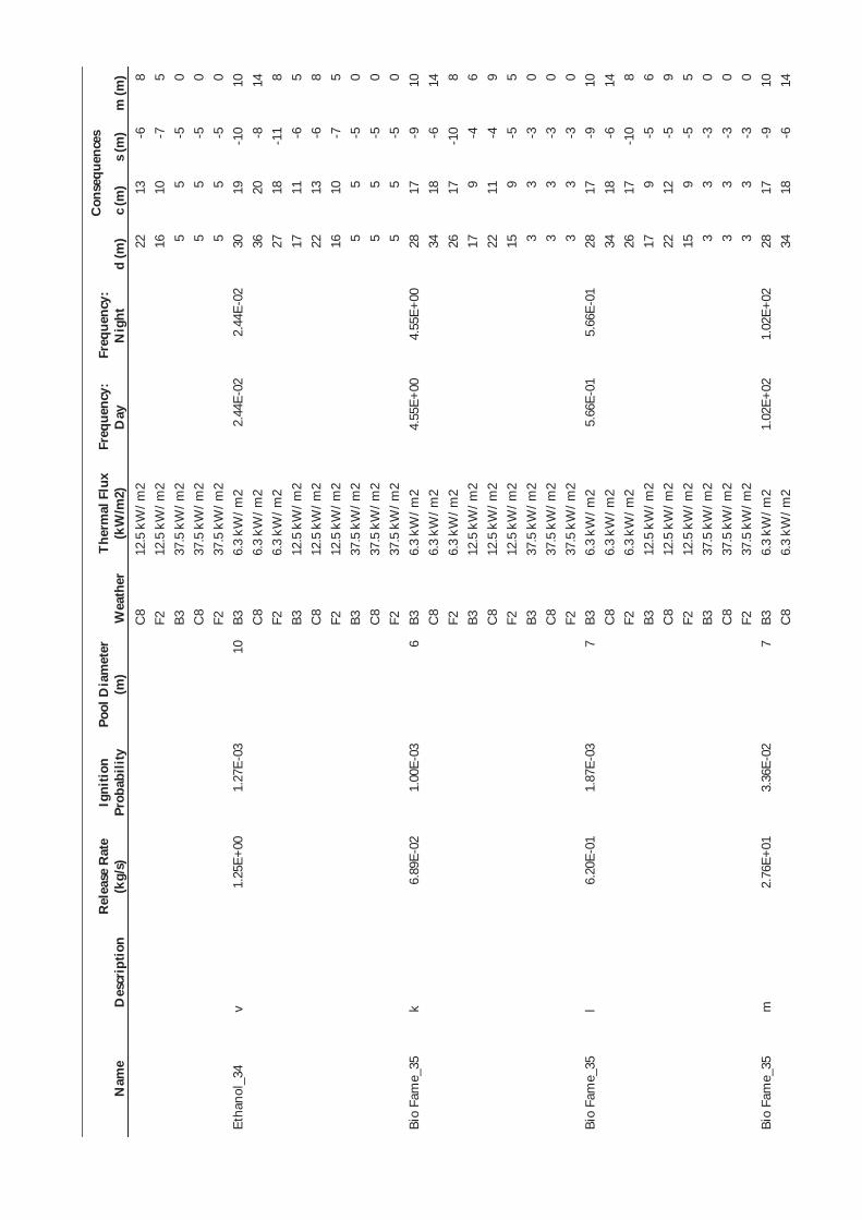
Nam
e D
escr
iptio
n R
elea
se R
ate
(kg/
s)
Igni
tion
Prob
abili
ty
Pool
Dia
met
er
(m)
Wea
ther
Th
erm
al F
lux
(kW
/m2)
Fr
eque
ncy:
D
ay
Freq
uenc
y:
Nig
ht
Con
sequ
ence
s
d (m
) c
(m)
s (m
) m
(m)
C8
12.5
kW
/m2
22
13
-6
8 F2
12
.5 k
W/m
2 16
10
-7
5
B3
37.5
kW
/m2
5 5
-5
0 C
8 37
.5 k
W/m
2 5
5 -5
0
F2
37.5
kW
/m2
5 5
-5
0 Et
hano
l_34
v
1.25
E+00
1.
27E-
03
10
B3
6.3
kW/m
2 2.
44E-
02
2.44
E-02
30
19
-1
0 10
C
8 6.
3 kW
/m2
36
20
-8
14
F2
6.3
kW/m
2 27
18
-1
1 8
B3
12.5
kW
/m2
17
11
-6
5 C
8 12
.5 k
W/m
2 22
13
-6
8
F2
12.5
kW
/m2
16
10
-7
5 B3
37
.5 k
W/m
2 5
5 -5
0
C8
37.5
kW
/m2
5 5
-5
0 F2
37
.5 k
W/m
2 5
5 -5
0
Bio
Fam
e_35
k
6.89
E-02
1.
00E-
03
6 B3
6.
3 kW
/m2
4.55
E+00
4.
55E+
00
28
17
-9
10
C8
6.3
kW/m
2 34
18
-6
14
F2
6.
3 kW
/m2
26
17
-10
8 B3
12
.5 k
W/m
2 17
9
-4
6 C
8 12
.5 k
W/m
2 22
11
-4
9
F2
12.5
kW
/m2
15
9 -5
5
B3
37.5
kW
/m2
3 3
-3
0 C
8 37
.5 k
W/m
2 3
3 -3
0
F2
37.5
kW
/m2
3 3
-3
0 Bi
o Fa
me_
35
l 6.
20E-
01
1.87
E-03
7
B3
6.3
kW/m
2 5.
66E-
01
5.66
E-01
28
17
-9
10
C
8 6.
3 kW
/m2
34
18
-6
14
F2
6.3
kW/m
2 26
17
-1
0 8
B3
12.5
kW
/m2
17
9 -5
6
C8
12.5
kW
/m2
22
12
-5
9 F2
12
.5 k
W/m
2 15
9
-5
5 B3
37
.5 k
W/m
2 3
3 -3
0
C8
37.5
kW
/m2
3 3
-3
0 F2
37
.5 k
W/m
2 3
3 -3
0
Bio
Fam
e_35
m
2.
76E+
01
3.36
E-02
7
B3
6.3
kW/m
2 1.
02E+
02
1.02
E+02
28
17
-9
10
C
8 6.
3 kW
/m2
34
18
-6
14
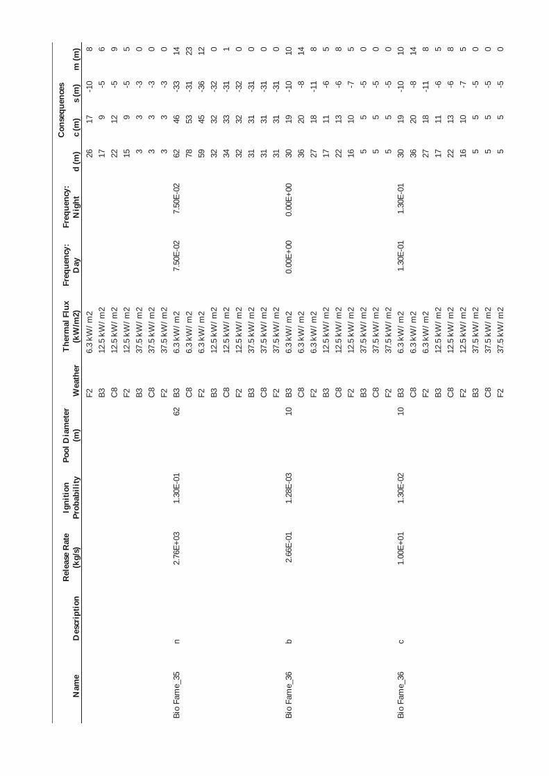
Nam
e D
escr
iptio
n R
elea
se R
ate
(kg/
s)
Igni
tion
Prob
abili
ty
Pool
Dia
met
er
(m)
Wea
ther
Th
erm
al F
lux
(kW
/m2)
Fr
eque
ncy:
D
ay
Freq
uenc
y:
Nig
ht
Con
sequ
ence
s
d (m
) c
(m)
s (m
) m
(m)
F2
6.3
kW/m
2 26
17
-1
0 8
B3
12.5
kW
/m2
17
9 -5
6
C8
12.5
kW
/m2
22
12
-5
9 F2
12
.5 k
W/m
2 15
9
-5
5 B3
37
.5 k
W/m
2 3
3 -3
0
C8
37.5
kW
/m2
3 3
-3
0 F2
37
.5 k
W/m
2 3
3 -3
0
Bio
Fam
e_35
n
2.76
E+03
1.
30E-
01
62
B3
6.3
kW/m
2 7.
50E-
02
7.50
E-02
62
46
-3
3 14
C
8 6.
3 kW
/m2
78
53
-31
23
F2
6.3
kW/m
2 59
45
-3
6 12
B3
12
.5 k
W/m
2 32
32
-3
2 0
C8
12.5
kW
/m2
34
33
-31
1 F2
12
.5 k
W/m
2 32
32
-3
2 0
B3
37.5
kW
/m2
31
31
-31
0 C
8 37
.5 k
W/m
2 31
31
-3
1 0
F2
37.5
kW
/m2
31
31
-31
0 Bi
o Fa
me_
36
b 2.
66E-
01
1.28
E-03
10
B3
6.
3 kW
/m2
0.00
E+00
0.
00E+
00
30
19
-10
10
C8
6.3
kW/m
2 36
20
-8
14
F2
6.
3 kW
/m2
27
18
-11
8 B3
12
.5 k
W/m
2 17
11
-6
5
C8
12.5
kW
/m2
22
13
-6
8 F2
12
.5 k
W/m
2 16
10
-7
5
B3
37.5
kW
/m2
5 5
-5
0 C
8 37
.5 k
W/m
2 5
5 -5
0
F2
37.5
kW
/m2
5 5
-5
0 Bi
o Fa
me_
36
c 1.
00E+
01
1.30
E-02
10
B3
6.
3 kW
/m2
1.30
E-01
1.
30E-
01
30
19
-10
10
C8
6.3
kW/m
2 36
20
-8
14
F2
6.
3 kW
/m2
27
18
-11
8 B3
12
.5 k
W/m
2 17
11
-6
5
C8
12.5
kW
/m2
22
13
-6
8 F2
12
.5 k
W/m
2 16
10
-7
5
B3
37.5
kW
/m2
5 5
-5
0 C
8 37
.5 k
W/m
2 5
5 -5
0
F2
37.5
kW
/m2
5 5
-5
0

Nam
e D
escr
iptio
n R
elea
se R
ate
(kg/
s)
Igni
tion
Prob
abili
ty
Pool
Dia
met
er
(m)
Wea
ther
Th
erm
al F
lux
(kW
/m2)
Fr
eque
ncy:
D
ay
Freq
uenc
y:
Nig
ht
Con
sequ
ence
s
d (m
) c
(m)
s (m
) m
(m)
Bio
Fam
e_36
d
4.61
E+00
6.
72E-
03
10
B3
6.3
kW/m
2 0.
00E+
00
0.00
E+00
30
19
-1
0 10
C
8 6.
3 kW
/m2
36
20
-8
14
F2
6.3
kW/m
2 27
18
-1
1 8
B3
12.5
kW
/m2
17
11
-6
5 C
8 12
.5 k
W/m
2 22
13
-6
8
F2
12.5
kW
/m2
16
10
-7
5 B3
37
.5 k
W/m
2 5
5 -5
0
C8
37.5
kW
/m2
5 5
-5
0 F2
37
.5 k
W/m
2 5
5 -5
0
Bio
Fam
e_36
e
1.00
E+01
1.
30E-
02
10
B3
6.3
kW/m
2 6.
51E-
02
6.51
E-02
30
19
-1
0 10
C
8 6.
3 kW
/m2
36
20
-8
14
F2
6.3
kW/m
2 27
18
-1
1 8
B3
12.5
kW
/m2
17
11
-6
5 C
8 12
.5 k
W/m
2 22
13
-6
8
F2
12.5
kW
/m2
16
10
-7
5 B3
37
.5 k
W/m
2 5
5 -5
0
C8
37.5
kW
/m2
5 5
-5
0 F2
37
.5 k
W/m
2 5
5 -5
0
Bio
Fam
e_36
p
1.00
E+01
1.
30E-
02
10
B3
6.3
kW/m
2 1.
95E-
01
1.95
E-01
30
19
-1
0 10
C
8 6.
3 kW
/m2
36
20
-8
14
F2
6.3
kW/m
2 27
18
-1
1 8
B3
12.5
kW
/m2
17
11
-6
5 C
8 12
.5 k
W/m
2 22
13
-6
8
F2
12.5
kW
/m2
16
10
-7
5 B3
37
.5 k
W/m
2 5
5 -5
0
C8
37.5
kW
/m2
5 5
-5
0 F2
37
.5 k
W/m
2 5
5 -5
0
Bio
Fam
e_36
f
2.80
E+00
4.
61E-
03
10
B3
6.3
kW/m
2 1.
86E-
02
1.86
E-02
30
19
-1
0 10
C
8 6.
3 kW
/m2
36
20
-8
14
F2
6.3
kW/m
2 27
18
-1
1 8
B3
12.5
kW
/m2
17
11
-6
5 C
8 12
.5 k
W/m
2 22
13
-6
8
F2
12.5
kW
/m2
16
10
-7
5 B3
37
.5 k
W/m
2 5
5 -5
0
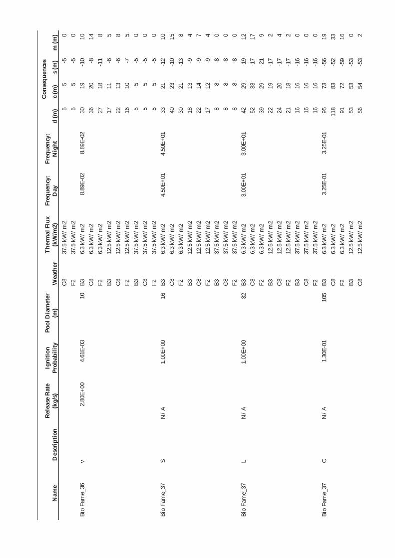
Nam
e D
escr
iptio
n R
elea
se R
ate
(kg/
s)
Igni
tion
Prob
abili
ty
Pool
Dia
met
er
(m)
Wea
ther
Th
erm
al F
lux
(kW
/m2)
Fr
eque
ncy:
D
ay
Freq
uenc
y:
Nig
ht
Con
sequ
ence
s
d (m
) c
(m)
s (m
) m
(m)
C8
37.5
kW
/m2
5 5
-5
0 F2
37
.5 k
W/m
2 5
5 -5
0
Bio
Fam
e_36
v
2.80
E+00
4.
61E-
03
10
B3
6.3
kW/m
2 8.
89E-
02
8.89
E-02
30
19
-1
0 10
C
8 6.
3 kW
/m2
36
20
-8
14
F2
6.3
kW/m
2 27
18
-1
1 8
B3
12.5
kW
/m2
17
11
-6
5 C
8 12
.5 k
W/m
2 22
13
-6
8
F2
12.5
kW
/m2
16
10
-7
5 B3
37
.5 k
W/m
2 5
5 -5
0
C8
37.5
kW
/m2
5 5
-5
0 F2
37
.5 k
W/m
2 5
5 -5
0
Bio
Fam
e_37
S
N/A
1.
00E+
00
16
B3
6.3
kW/m
2 4.
50E+
01
4.50
E+01
33
21
-1
2 10
C
8 6.
3 kW
/m2
40
23
-10
15
F2
6.3
kW/m
2 30
21
-1
3 8
B3
12.5
kW
/m2
18
13
-9
4 C
8 12
.5 k
W/m
2 22
14
-9
7
F2
12.5
kW
/m2
17
12
-9
4 B3
37
.5 k
W/m
2 8
8 -8
0
C8
37.5
kW
/m2
8 8
-8
0 F2
37
.5 k
W/m
2 8
8 -8
0
Bio
Fam
e_37
L
N/A
1.
00E+
00
32
B3
6.3
kW/m
2 3.
00E+
01
3.00
E+01
42
29
-1
9 12
C
8 6.
3 kW
/m2
52
33
-17
17
F2
6.3
kW/m
2 39
29
-2
1 9
B3
12.5
kW
/m2
22
19
-17
2 C
8 12
.5 k
W/m
2 24
20
-1
7 4
F2
12.5
kW
/m2
21
18
-17
2 B3
37
.5 k
W/m
2 16
16
-1
6 0
C8
37.5
kW
/m2
16
16
-16
0 F2
37
.5 k
W/m
2 16
16
-1
6 0
Bio
Fam
e_37
C
N
/A
1.30
E-01
10
5 B3
6.
3 kW
/m2
3.25
E-01
3.
25E-
01
95
73
-56
19
C8
6.3
kW/m
2 11
8 83
-5
2 33
F2
6.
3 kW
/m2
91
72
-59
16
B3
12.5
kW
/m2
53
53
-53
0 C
8 12
.5 k
W/m
2 56
54
-5
3 2

Nam
e D
escr
iptio
n R
elea
se R
ate
(kg/
s)
Igni
tion
Prob
abili
ty
Pool
Dia
met
er
(m)
Wea
ther
Th
erm
al F
lux
(kW
/m2)
Fr
eque
ncy:
D
ay
Freq
uenc
y:
Nig
ht
Con
sequ
ence
s
d (m
) c
(m)
s (m
) m
(m)
F2
12.5
kW
/m2
53
53
-53
0 B3
37
.5 k
W/m
2 53
53
-5
3 0
C8
37.5
kW
/m2
53
53
-53
0 F2
37
.5 k
W/m
2 53
53
-5
3 0
Bio
Fam
e_38
b
2.66
E-01
1.
28E-
03
11
B3
6.3
kW/m
2 2.
55E-
01
2.55
E-01
31
19
-1
1 10
C
8 6.
3 kW
/m2
37
21
-8
14
F2
6.3
kW/m
2 28
19
-1
2 8
B3
12.5
kW
/m2
17
11
-7
5 C
8 12
.5 k
W/m
2 22
13
-7
8
F2
12.5
kW
/m2
16
10
-7
4 B3
37
.5 k
W/m
2 6
6 -6
0
C8
37.5
kW
/m2
6 6
-6
0 F2
37
.5 k
W/m
2 6
6 -6
0
Bio
Fam
e_38
c
1.00
E+01
1.
30E-
02
56
B3
6.3
kW/m
2 1.
82E+
00
1.82
E+00
58
43
-3
0 14
C
8 6.
3 kW
/m2
72
49
-28
22
F2
6.3
kW/m
2 55
42
-3
2 11
B3
12
.5 k
W/m
2 30
29
-2
9 1
C8
12.5
kW
/m2
32
31
-29
2 F2
12
.5 k
W/m
2 30
29
-2
9 0
B3
37.5
kW
/m2
28
28
-28
0 C
8 37
.5 k
W/m
2 28
28
-2
8 0
F2
37.5
kW
/m2
28
28
-28
0 Bi
o Fa
me_
38
d 1.
00E+
01
1.30
E-02
56
B3
6.
3 kW
/m2
1.04
E+00
1.
04E+
00
58
43
-30
14
C8
6.3
kW/m
2 72
49
-2
8 22
F2
6.
3 kW
/m2
55
42
-32
11
B3
12.5
kW
/m2
30
29
-29
1 C
8 12
.5 k
W/m
2 32
31
-2
9 2
F2
12.5
kW
/m2
30
29
-29
0 B3
37
.5 k
W/m
2 28
28
-2
8 0
C8
37.5
kW
/m2
28
28
-28
0 F2
37
.5 k
W/m
2 28
28
-2
8 0
Bio
Fam
e_38
e
1.00
E+01
1.
30E-
02
56
B3
6.3
kW/m
2 5.
21E-
01
5.21
E-01
58
43
-3
0 14
C
8 6.
3 kW
/m2
72
49
-28
22
F2
6.3
kW/m
2 55
42
-3
2 11
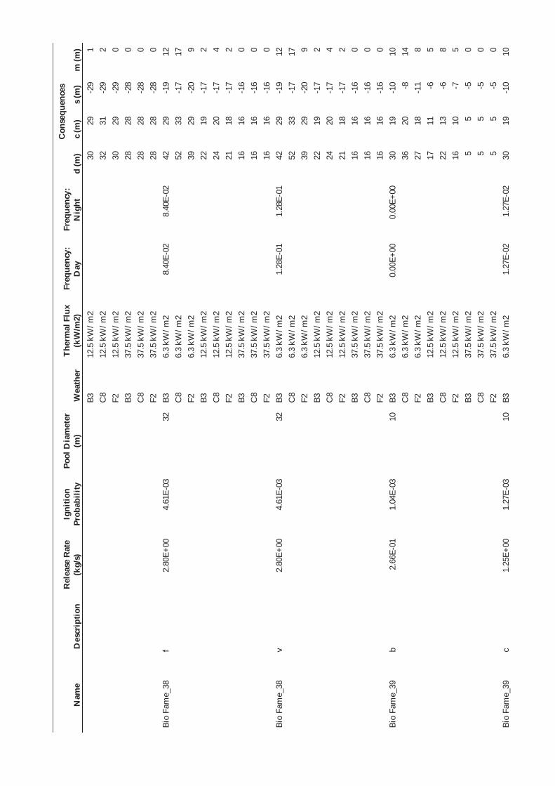
Nam
e D
escr
iptio
n R
elea
se R
ate
(kg/
s)
Igni
tion
Prob
abili
ty
Pool
Dia
met
er
(m)
Wea
ther
Th
erm
al F
lux
(kW
/m2)
Fr
eque
ncy:
D
ay
Freq
uenc
y:
Nig
ht
Con
sequ
ence
s
d (m
) c
(m)
s (m
) m
(m)
B3
12.5
kW
/m2
30
29
-29
1 C
8 12
.5 k
W/m
2 32
31
-2
9 2
F2
12.5
kW
/m2
30
29
-29
0 B3
37
.5 k
W/m
2 28
28
-2
8 0
C8
37.5
kW
/m2
28
28
-28
0 F2
37
.5 k
W/m
2 28
28
-2
8 0
Bio
Fam
e_38
f
2.80
E+00
4.
61E-
03
32
B3
6.3
kW/m
2 8.
40E-
02
8.40
E-02
42
29
-1
9 12
C
8 6.
3 kW
/m2
52
33
-17
17
F2
6.3
kW/m
2 39
29
-2
0 9
B3
12.5
kW
/m2
22
19
-17
2 C
8 12
.5 k
W/m
2 24
20
-1
7 4
F2
12.5
kW
/m2
21
18
-17
2 B3
37
.5 k
W/m
2 16
16
-1
6 0
C8
37.5
kW
/m2
16
16
-16
0 F2
37
.5 k
W/m
2 16
16
-1
6 0
Bio
Fam
e_38
v
2.80
E+00
4.
61E-
03
32
B3
6.3
kW/m
2 1.
28E-
01
1.28
E-01
42
29
-1
9 12
C
8 6.
3 kW
/m2
52
33
-17
17
F2
6.3
kW/m
2 39
29
-2
0 9
B3
12.5
kW
/m2
22
19
-17
2 C
8 12
.5 k
W/m
2 24
20
-1
7 4
F2
12.5
kW
/m2
21
18
-17
2 B3
37
.5 k
W/m
2 16
16
-1
6 0
C8
37.5
kW
/m2
16
16
-16
0 F2
37
.5 k
W/m
2 16
16
-1
6 0
Bio
Fam
e_39
b
2.66
E-01
1.
04E-
03
10
B3
6.3
kW/m
2 0.
00E+
00
0.00
E+00
30
19
-1
0 10
C
8 6.
3 kW
/m2
36
20
-8
14
F2
6.3
kW/m
2 27
18
-1
1 8
B3
12.5
kW
/m2
17
11
-6
5 C
8 12
.5 k
W/m
2 22
13
-6
8
F2
12.5
kW
/m2
16
10
-7
5 B3
37
.5 k
W/m
2 5
5 -5
0
C8
37.5
kW
/m2
5 5
-5
0 F2
37
.5 k
W/m
2 5
5 -5
0
Bio
Fam
e_39
c
1.25
E+00
1.
27E-
03
10
B3
6.3
kW/m
2 1.
27E-
02
1.27
E-02
30
19
-1
0 10

Nam
e D
escr
iptio
n R
elea
se R
ate
(kg/
s)
Igni
tion
Prob
abili
ty
Pool
Dia
met
er
(m)
Wea
ther
Th
erm
al F
lux
(kW
/m2)
Fr
eque
ncy:
D
ay
Freq
uenc
y:
Nig
ht
Con
sequ
ence
s
d (m
) c
(m)
s (m
) m
(m)
C8
6.3
kW/m
2 36
20
-8
14
F2
6.
3 kW
/m2
27
18
-11
8 B3
12
.5 k
W/m
2 17
11
-6
5
C8
12.5
kW
/m2
22
13
-6
8 F2
12
.5 k
W/m
2 16
10
-7
5
B3
37.5
kW
/m2
5 5
-5
0 C
8 37
.5 k
W/m
2 5
5 -5
0
F2
37.5
kW
/m2
5 5
-5
0 Bi
o Fa
me_
39
d 1.
25E+
00
1.27
E-03
10
B3
6.
3 kW
/m2
0.00
E+00
0.
00E+
00
30
19
-10
10
C8
6.3
kW/m
2 36
20
-8
14
F2
6.
3 kW
/m2
27
18
-11
8 B3
12
.5 k
W/m
2 17
11
-6
5
C8
12.5
kW
/m2
22
13
-6
8 F2
12
.5 k
W/m
2 16
10
-7
5
B3
37.5
kW
/m2
5 5
-5
0 C
8 37
.5 k
W/m
2 5
5 -5
0
F2
37.5
kW
/m2
5 5
-5
0 Bi
o Fa
me_
39
e 1.
25E+
00
1.27
E-03
10
B3
6.
3 kW
/m2
6.33
E-03
6.
33E-
03
30
19
-10
10
C8
6.3
kW/m
2 36
20
-8
14
F2
6.
3 kW
/m2
27
18
-11
8 B3
12
.5 k
W/m
2 17
11
-6
5
C8
12.5
kW
/m2
22
13
-6
8 F2
12
.5 k
W/m
2 16
10
-7
5
B3
37.5
kW
/m2
5 5
-5
0 C
8 37
.5 k
W/m
2 5
5 -5
0
F2
37.5
kW
/m2
5 5
-5
0 Bi
o Fa
me_
39
p 1.
25E+
00
1.27
E-03
10
B3
6.
3 kW
/m2
1.90
E-02
1.
90E-
02
30
19
-10
10
C8
6.3
kW/m
2 36
20
-8
14
F2
6.
3 kW
/m2
27
18
-11
8 B3
12
.5 k
W/m
2 17
11
-6
5
C8
12.5
kW
/m2
22
13
-6
8 F2
12
.5 k
W/m
2 16
10
-7
5
B3
37.5
kW
/m2
5 5
-5
0 C
8 37
.5 k
W/m
2 5
5 -5
0

Nam
e D
escr
iptio
n R
elea
se R
ate
(kg/
s)
Igni
tion
Prob
abili
ty
Pool
Dia
met
er
(m)
Wea
ther
Th
erm
al F
lux
(kW
/m2)
Fr
eque
ncy:
D
ay
Freq
uenc
y:
Nig
ht
Con
sequ
ence
s
d (m
) c
(m)
s (m
) m
(m)
F2
37.5
kW
/m2
5 5
-5
0 Bi
o Fa
me_
39
f 1.
25E+
00
1.27
E-03
10
B3
6.
3 kW
/m2
5.12
E-03
5.
12E-
03
30
19
-10
10
C8
6.3
kW/m
2 36
20
-8
14
F2
6.
3 kW
/m2
27
18
-11
8 B3
12
.5 k
W/m
2 17
11
-6
5
C8
12.5
kW
/m2
22
13
-6
8 F2
12
.5 k
W/m
2 16
10
-7
5
B3
37.5
kW
/m2
5 5
-5
0 C
8 37
.5 k
W/m
2 5
5 -5
0
F2
37.5
kW
/m2
5 5
-5
0 Bi
o Fa
me_
39
v 1.
25E+
00
1.27
E-03
10
B3
6.
3 kW
/m2
2.44
E-02
2.
44E-
02
30
19
-10
10
C8
6.3
kW/m
2 36
20
-8
14
F2
6.
3 kW
/m2
27
18
-11
8 B3
12
.5 k
W/m
2 17
11
-6
5
C8
12.5
kW
/m2
22
13
-6
8 F2
12
.5 k
W/m
2 16
10
-7
5
B3
37.5
kW
/m2
5 5
-5
0 C
8 37
.5 k
W/m
2 5
5 -5
0
F2
37.5
kW
/m2
5 5
-5
0
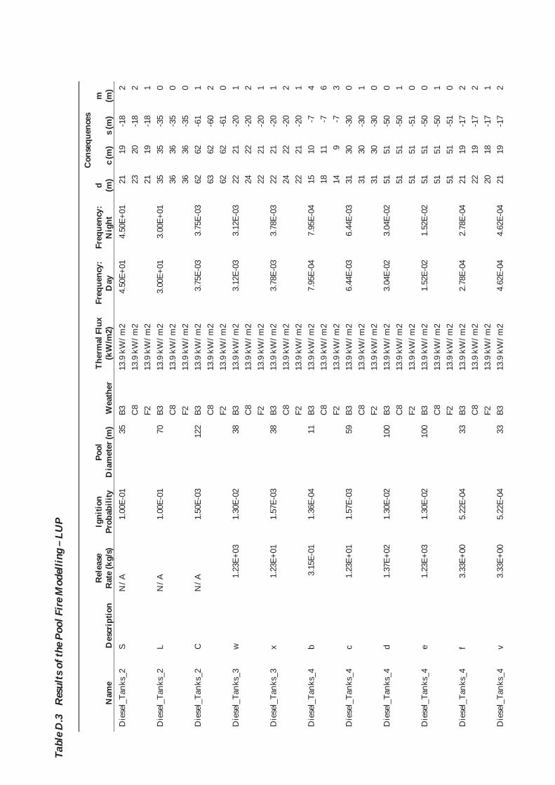
Tabl
e D
.3
Res
ults
of t
he P
ool F
ire M
odel
ling
– LU
P
Nam
e D
escr
iptio
n R
elea
se
Rat
e (k
g/s)
Ig
nitio
n Pr
obab
ility
Po
ol
Dia
met
er (m
) W
eath
er
Ther
mal
Flu
x (k
W/m
2)
Freq
uenc
y:
Day
Fr
eque
ncy:
N
ight
Con
sequ
ence
s d (m
) c
(m)
s (m
) m
(m
) D
iese
l_Ta
nks_
2 S
N/A
1.
00E-
01
35
B3
13.9
kW
/m2
4.50
E+01
4.
50E+
01
21
19
-18
2 C
8 13
.9 k
W/m
2 23
20
-1
8 2
F2
13.9
kW
/m2
21
19
-18
1 D
iese
l_Ta
nks_
2 L
N/A
1.
00E-
01
70
B3
13.9
kW
/m2
3.00
E+01
3.
00E+
01
35
35
-35
0 C
8 13
.9 k
W/m
2 36
36
-3
5 0
F2
13.9
kW
/m2
36
36
-35
0 D
iese
l_Ta
nks_
2 C
N
/A
1.50
E-03
12
2 B3
13
.9 k
W/m
2 3.
75E-
03
3.75
E-03
62
62
-6
1 1
C8
13.9
kW
/m2
63
62
-60
2 F2
13
.9 k
W/m
2 62
62
-6
1 0
Die
sel_
Tank
s_3
w
1.23
E+03
1.
30E-
02
38
B3
13.9
kW
/m2
3.12
E-03
3.
12E-
03
22
21
-20
1 C
8 13
.9 k
W/m
2 24
22
-2
0 2
F2
13.9
kW
/m2
22
21
-20
1 D
iese
l_Ta
nks_
3 x
1.23
E+01
1.
57E-
03
38
B3
13.9
kW
/m2
3.78
E-03
3.
78E-
03
22
21
-20
1 C
8 13
.9 k
W/m
2 24
22
-2
0 2
F2
13.9
kW
/m2
22
21
-20
1 D
iese
l_Ta
nks_
4 b
3.15
E-01
1.
36E-
04
11
B3
13.9
kW
/m2
7.95
E-04
7.
95E-
04
15
10
-7
4 C
8 13
.9 k
W/m
2 18
11
-7
6
F2
13.9
kW
/m2
14
9 -7
3
Die
sel_
Tank
s_4
c 1.
23E+
01
1.57
E-03
59
B3
13
.9 k
W/m
2 6.
44E-
03
6.44
E-03
31
30
-3
0 0
C8
13.9
kW
/m2
31
30
-30
1 F2
13
.9 k
W/m
2 31
30
-3
0 0
Die
sel_
Tank
s_4
d 1.
37E+
02
1.30
E-02
10
0 B3
13
.9 k
W/m
2 3.
04E-
02
3.04
E-02
51
51
-5
0 0
C8
13.9
kW
/m2
51
51
-50
1 F2
13
.9 k
W/m
2 51
51
-5
1 0
Die
sel_
Tank
s_4
e 1.
23E+
03
1.30
E-02
10
0 B3
13
.9 k
W/m
2 1.
52E-
02
1.52
E-02
51
51
-5
0 0
C8
13.9
kW
/m2
51
51
-50
1 F2
13
.9 k
W/m
2 51
51
-5
1 0
Die
sel_
Tank
s_4
f 3.
33E+
00
5.22
E-04
33
B3
13
.9 k
W/m
2 2.
78E-
04
2.78
E-04
21
19
-1
7 2
C8
13.9
kW
/m2
22
19
-17
2 F2
13
.9 k
W/m
2 20
18
-1
7 1
Die
sel_
Tank
s_4
v 3.
33E+
00
5.22
E-04
33
B3
13
.9 k
W/m
2 4.
62E-
04
4.62
E-04
21
19
-1
7 2
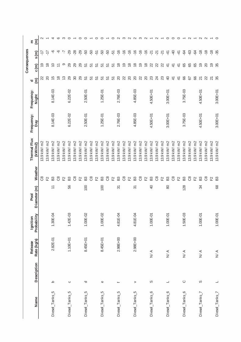
Nam
e D
escr
iptio
n R
elea
se
Rat
e (k
g/s)
Ig
nitio
n Pr
obab
ility
Po
ol
Dia
met
er (m
) W
eath
er
Ther
mal
Flu
x (k
W/m
2)
Freq
uenc
y:
Day
Fr
eque
ncy:
N
ight
Con
sequ
ence
s d (m
) c
(m)
s (m
) m
(m
) C
8 13
.9 k
W/m
2 22
19
-1
7 2
F2
13.9
kW
/m2
20
18
-17
1 D
iese
l_Ta
nks_
5 b
2.82
E-01
1.
30E-
04
11
B3
13.9
kW
/m2
8.14
E-03
8.
14E-
03
15
10
-6
4 C
8 13
.9 k
W/m
2 18
11
-6
6
F2
13.9
kW
/m2
13
9 -7
3
Die
sel_
Tank
s_5
c 1.
10E+
01
1.42
E-03
56
B3
13
.9 k
W/m
2 6.
22E-
02
6.22
E-02
29
29
-2
9 0
C8
13.9
kW
/m2
30
29
-28
1 F2
13
.9 k
W/m
2 29
29
-2
9 0
Die
sel_
Tank
s_5
d 8.
45E+
01
1.00
E-02
10
0 B3
13
.9 k
W/m
2 2.
50E-
01
2.50
E-01
51
51
-5
0 0
C8
13.9
kW
/m2
51
51
-50
1 F2
13
.9 k
W/m
2 51
51
-5
1 0
Die
sel_
Tank
s_5
e 8.
45E+
01
1.00
E-02
10
0 B3
13
.9 k
W/m
2 1.
25E-
01
1.25
E-01
51
51
-5
0 0
C8
13.9
kW
/m2
51
51
-50
1 F2
13
.9 k
W/m
2 51
51
-5
1 0
Die
sel_
Tank
s_5
f 2.
98E+
00
4.81
E-04
31
B3
13
.9 k
W/m
2 2.
76E-
03
2.76
E-03
20
18
-1
6 2
C8
13.9
kW
/m2
22
19
-16
3 F2
13
.9 k
W/m
2 20
18
-1
6 2
Die
sel_
Tank
s_5
v 2.
98E+
00
4.81
E-04
31
B3
13
.9 k
W/m
2 4.
85E-
03
4.85
E-03
20
18
-1
6 2
C8
13.9
kW
/m2
22
19
-16
3 F2
13
.9 k
W/m
2 20
18
-1
6 2
Die
sel_
Tank
s_6
S N
/A
1.00
E-01
40
B3
13
.9 k
W/m
2 4.
50E+
01
4.50
E+01
23
22
-2
1 1
C8
13.9
kW
/m2
24
22
-21
2 F2
13
.9 k
W/m
2 23
22
-2
1 1
Die
sel_
Tank
s_6
L N
/A
1.00
E-01
80
B3
13
.9 k
W/m
2 3.
00E+
01
3.00
E+01
40
41
-4
1 0
C8
13.9
kW
/m2
41
41
-40
0 F2
13
.9 k
W/m
2 41
41
-4
1 0
Die
sel_
Tank
s_6
C
N/A
1.
50E-
03
128
B3
13.9
kW
/m2
3.75
E-03
3.
75E-
03
66
65
-64
1 C
8 13
.9 k
W/m
2 67
65
-6
3 2
F2
13.9
kW
/m2
66
65
-64
1 D
iese
l_Ta
nks_
7 S
N/A
1.
00E-
01
34
B3
13.9
kW
/m2
4.50
E+01
4.
50E+
01
21
19
-18
2 C
8 13
.9 k
W/m
2 22
20
-1
8 2
F2
13.9
kW
/m2
21
19
-18
1 D
iese
l_Ta
nks_
7 L
N/A
1.
00E-
01
68
B3
13.9
kW
/m2
3.00
E+01
3.
00E+
01
35
35
-35
0

Nam
e D
escr
iptio
n R
elea
se
Rat
e (k
g/s)
Ig
nitio
n Pr
obab
ility
Po
ol
Dia
met
er (m
) W
eath
er
Ther
mal
Flu
x (k
W/m
2)
Freq
uenc
y:
Day
Fr
eque
ncy:
N
ight
Con
sequ
ence
s d (m
) c
(m)
s (m
) m
(m
) C
8 13
.9 k
W/m
2 35
35
-3
4 0
F2
13.9
kW
/m2
35
35
-35
0 D
iese
l_Ta
nks_
7 C
N
/A
1.50
E-03
12
1 B3
13
.9 k
W/m
2 3.
75E-
03
3.75
E-03
62
62
-6
1 1
C8
13.9
kW
/m2
63
61
-60
2 F2
13
.9 k
W/m
2 62
62
-6
1 0
Die
sel_
Tank
s_8
S N
/A
1.00
E-01
43
B3
13
.9 k
W/m
2 4.
50E+
01
4.50
E+01
24
23
-2
2 1
C8
13.9
kW
/m2
25
23
-22
2 F2
13
.9 k
W/m
2 24
23
-2
2 1
Die
sel_
Tank
s_8
L N
/A
1.00
E-01
85
B3
13
.9 k
W/m
2 3.
00E+
01
3.00
E+01
43
43
-4
3 0
C8
13.9
kW
/m2
44
43
-43
0 F2
13
.9 k
W/m
2 43
43
-4
3 0
Die
sel_
Tank
s_8
C
N/A
1.
50E-
03
132
B3
13.9
kW
/m2
3.75
E-03
3.
75E-
03
68
67
-66
1 C
8 13
.9 k
W/m
2 69
67
-6
5 2
F2
13.9
kW
/m2
68
67
-66
1 D
iese
l_Ta
nks_
9 S
N/A
1.
00E-
01
50
B3
13.9
kW
/m2
4.50
E+01
4.
50E+
01
27
26
-26
1 C
8 13
.9 k
W/m
2 28
27
-2
6 1
F2
13.9
kW
/m2
27
26
-26
1 D
iese
l_Ta
nks_
9 L
N/A
1.
00E-
01
101
B3
13.9
kW
/m2
3.00
E+01
3.
00E+
01
51
51
-51
0 C
8 13
.9 k
W/m
2 52
51
-5
0 1
F2
13.9
kW
/m2
51
51
-51
0 D
iese
l_Ta
nks_
9 C
N
/A
1.50
E-03
14
2 B3
13
.9 k
W/m
2 3.
75E-
03
3.75
E-03
73
72
-7
1 1
C8
13.9
kW
/m2
75
72
-70
2 F2
13
.9 k
W/m
2 73
72
-7
1 1
Die
sel_
Tank
s_10
S
N/A
1.
00E-
01
50
B3
13.9
kW
/m2
4.50
E+01
4.
50E+
01
27
26
-26
1 C
8 13
.9 k
W/m
2 28
27
-2
6 1
F2
13.9
kW
/m2
27
26
-26
1 D
iese
l_Ta
nks_
10
L N
/A
1.00
E-01
10
1 B3
13
.9 k
W/m
2 3.
00E+
01
3.00
E+01
51
51
-5
1 0
C8
13.9
kW
/m2
52
51
-50
1 F2
13
.9 k
W/m
2 51
51
-5
1 0
Die
sel_
Tank
s_10
C
N
/A
1.50
E-03
14
2 B3
13
.9 k
W/m
2 3.
75E-
03
3.75
E-03
73
72
-7
1 1
C8
13.9
kW
/m2
75
72
-70
2 F2
13
.9 k
W/m
2 73
72
-7
1 1
Die
sel_
Tank
s_11
S
N/A
1.
00E-
01
44
B3
13.9
kW
/m2
4.50
E+01
4.
50E+
01
24
23
-23
1
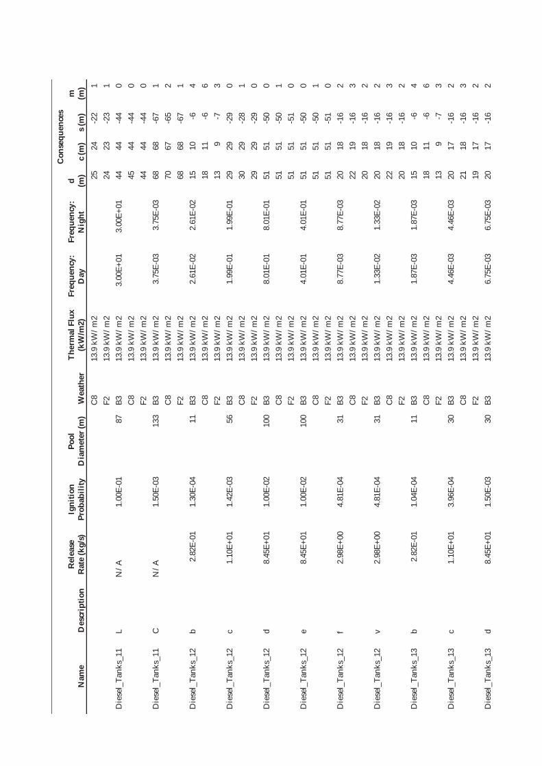
Nam
e D
escr
iptio
n R
elea
se
Rat
e (k
g/s)
Ig
nitio
n Pr
obab
ility
Po
ol
Dia
met
er (m
) W
eath
er
Ther
mal
Flu
x (k
W/m
2)
Freq
uenc
y:
Day
Fr
eque
ncy:
N
ight
Con
sequ
ence
s d (m
) c
(m)
s (m
) m
(m
) C
8 13
.9 k
W/m
2 25
24
-2
2 1
F2
13.9
kW
/m2
24
23
-23
1 D
iese
l_Ta
nks_
11
L N
/A
1.00
E-01
87
B3
13
.9 k
W/m
2 3.
00E+
01
3.00
E+01
44
44
-4
4 0
C8
13.9
kW
/m2
45
44
-44
0 F2
13
.9 k
W/m
2 44
44
-4
4 0
Die
sel_
Tank
s_11
C
N
/A
1.50
E-03
13
3 B3
13
.9 k
W/m
2 3.
75E-
03
3.75
E-03
68
68
-6
7 1
C8
13.9
kW
/m2
70
67
-65
2 F2
13
.9 k
W/m
2 68
68
-6
7 1
Die
sel_
Tank
s_12
b
2.82
E-01
1.
30E-
04
11
B3
13.9
kW
/m2
2.61
E-02
2.
61E-
02
15
10
-6
4 C
8 13
.9 k
W/m
2 18
11
-6
6
F2
13.9
kW
/m2
13
9 -7
3
Die
sel_
Tank
s_12
c
1.10
E+01
1.
42E-
03
56
B3
13.9
kW
/m2
1.99
E-01
1.
99E-
01
29
29
-29
0 C
8 13
.9 k
W/m
2 30
29
-2
8 1
F2
13.9
kW
/m2
29
29
-29
0 D
iese
l_Ta
nks_
12
d 8.
45E+
01
1.00
E-02
10
0 B3
13
.9 k
W/m
2 8.
01E-
01
8.01
E-01
51
51
-5
0 0
C8
13.9
kW
/m2
51
51
-50
1 F2
13
.9 k
W/m
2 51
51
-5
1 0
Die
sel_
Tank
s_12
e
8.45
E+01
1.
00E-
02
100
B3
13.9
kW
/m2
4.01
E-01
4.
01E-
01
51
51
-50
0 C
8 13
.9 k
W/m
2 51
51
-5
0 1
F2
13.9
kW
/m2
51
51
-51
0 D
iese
l_Ta
nks_
12
f 2.
98E+
00
4.81
E-04
31
B3
13
.9 k
W/m
2 8.
77E-
03
8.77
E-03
20
18
-1
6 2
C8
13.9
kW
/m2
22
19
-16
3 F2
13
.9 k
W/m
2 20
18
-1
6 2
Die
sel_
Tank
s_12
v
2.98
E+00
4.
81E-
04
31
B3
13.9
kW
/m2
1.33
E-02
1.
33E-
02
20
18
-16
2 C
8 13
.9 k
W/m
2 22
19
-1
6 3
F2
13.9
kW
/m2
20
18
-16
2 D
iese
l_Ta
nks_
13
b 2.
82E-
01
1.04
E-04
11
B3
13
.9 k
W/m
2 1.
87E-
03
1.87
E-03
15
10
-6
4
C8
13.9
kW
/m2
18
11
-6
6 F2
13
.9 k
W/m
2 13
9
-7
3 D
iese
l_Ta
nks_
13
c 1.
10E+
01
3.96
E-04
30
B3
13
.9 k
W/m
2 4.
46E-
03
4.46
E-03
20
17
-1
6 2
C8
13.9
kW
/m2
21
18
-16
3 F2
13
.9 k
W/m
2 19
17
-1
6 2
Die
sel_
Tank
s_13
d
8.45
E+01
1.
50E-
03
30
B3
13.9
kW
/m2
6.75
E-03
6.
75E-
03
20
17
-16
2

Nam
e D
escr
iptio
n R
elea
se
Rat
e (k
g/s)
Ig
nitio
n Pr
obab
ility
Po
ol
Dia
met
er (m
) W
eath
er
Ther
mal
Flu
x (k
W/m
2)
Freq
uenc
y:
Day
Fr
eque
ncy:
N
ight
Con
sequ
ence
s d (m
) c
(m)
s (m
) m
(m
) C
8 13
.9 k
W/m
2 21
18
-1
6 3
F2
13.9
kW
/m2
19
17
-16
2 D
iese
l_Ta
nks_
13
e 8.
45E+
01
1.50
E-03
30
B3
13
.9 k
W/m
2 2.
36E-
03
2.36
E-03
20
17
-1
6 2
C8
13.9
kW
/m2
21
18
-16
3 F2
13
.9 k
W/m
2 19
17
-1
6 2
Die
sel_
Tank
s_13
f
2.98
E+00
1.
73E-
04
30
B3
13.9
kW
/m2
4.60
E-04
4.
60E-
04
20
17
-16
2 C
8 13
.9 k
W/m
2 21
18
-1
6 3
F2
13.9
kW
/m2
19
17
-16
2 D
iese
l_Ta
nks_
13
v 2.
98E+
00
1.73
E-04
30
B3
13
.9 k
W/m
2 1.
12E-
03
1.12
E-03
20
17
-1
6 2
C8
13.9
kW
/m2
21
18
-16
3 F2
13
.9 k
W/m
2 19
17
-1
6 2
Die
sel_
Tank
s_14
b
2.82
E-01
1.
04E-
04
11
B3
13.9
kW
/m2
1.87
E-03
1.
87E-
03
15
10
-6
4 C
8 13
.9 k
W/m
2 18
11
-6
6
F2
13.9
kW
/m2
13
9 -7
3
Die
sel_
Tank
s_14
c
1.10
E+01
3.
96E-
04
31
B3
13.9
kW
/m2
4.46
E-03
4.
46E-
03
20
18
-16
2 C
8 13
.9 k
W/m
2 22
19
-1
6 3
F2
13.9
kW
/m2
20
18
-17
2 D
iese
l_Ta
nks_
14
d 8.
45E+
01
1.50
E-03
31
B3
13
.9 k
W/m
2 6.
75E-
03
6.75
E-03
20
18
-1
6 2
C8
13.9
kW
/m2
22
19
-16
3 F2
13
.9 k
W/m
2 20
18
-1
7 2
Die
sel_
Tank
s_14
e
8.45
E+01
1.
50E-
03
31
B3
13.9
kW
/m2
2.36
E-03
2.
36E-
03
20
18
-16
2 C
8 13
.9 k
W/m
2 22
19
-1
6 3
F2
13.9
kW
/m2
20
18
-17
2 D
iese
l_Ta
nks_
14
f 2.
98E+
00
1.73
E-04
31
B3
13
.9 k
W/m
2 4.
60E-
04
4.60
E-04
20
18
-1
6 2
C8
13.9
kW
/m2
22
19
-16
3 F2
13
.9 k
W/m
2 20
18
-1
6 2
Die
sel_
Tank
s_14
v
2.98
E+00
1.
73E-
04
31
B3
13.9
kW
/m2
1.12
E-03
1.
12E-
03
20
18
-16
2 C
8 13
.9 k
W/m
2 22
19
-1
6 3
F2
13.9
kW
/m2
20
18
-16
2 D
iese
l_Ta
nks_
15
b 2.
82E-
01
1.04
E-04
11
B3
13
.9 k
W/m
2 4.
16E-
03
4.16
E-03
15
10
-6
4
C8
13.9
kW
/m2
18
11
-6
6 F2
13
.9 k
W/m
2 13
9
-7
3 D
iese
l_Ta
nks_
15
c 1.
10E+
01
3.96
E-04
43
B3
13
.9 k
W/m
2 9.
91E-
03
9.91
E-03
24
23
-2
2 1

Nam
e D
escr
iptio
n R
elea
se
Rat
e (k
g/s)
Ig
nitio
n Pr
obab
ility
Po
ol
Dia
met
er (m
) W
eath
er
Ther
mal
Flu
x (k
W/m
2)
Freq
uenc
y:
Day
Fr
eque
ncy:
N
ight
Con
sequ
ence
s d (m
) c
(m)
s (m
) m
(m
) C
8 13
.9 k
W/m
2 25
23
-2
2 2
F2
13.9
kW
/m2
24
23
-22
1 D
iese
l_Ta
nks_
15
d 8.
45E+
01
1.50
E-03
43
B3
13
.9 k
W/m
2 1.
50E-
02
1.50
E-02
24
23
-2
2 1
C8
13.9
kW
/m2
25
23
-22
2 F2
13
.9 k
W/m
2 24
23
-2
2 1
Die
sel_
Tank
s_15
e
8.45
E+01
1.
50E-
03
43
B3
13.9
kW
/m2
5.25
E-03
5.
25E-
03
24
23
-22
1 C
8 13
.9 k
W/m
2 25
23
-2
2 2
F2
13.9
kW
/m2
24
23
-22
1 D
iese
l_Ta
nks_
15
f 2.
98E+
00
1.73
E-04
31
B3
13
.9 k
W/m
2 1.
05E-
03
1.05
E-03
20
18
-1
6 2
C8
13.9
kW
/m2
22
19
-16
3 F2
13
.9 k
W/m
2 20
18
-1
6 2
Die
sel_
Tank
s_15
v
2.98
E+00
1.
73E-
04
31
B3
13.9
kW
/m2
2.23
E-03
2.
23E-
03
20
18
-16
2 C
8 13
.9 k
W/m
2 22
19
-1
6 3
F2
13.9
kW
/m2
20
18
-16
2 D
iese
l_Ta
nks_
16
b 2.
82E-
01
1.04
E-04
11
B3
13
.9 k
W/m
2 2.
08E-
03
2.08
E-03
15
10
-6
4
C8
13.9
kW
/m2
18
11
-6
6 F2
13
.9 k
W/m
2 13
9
-7
3 D
iese
l_Ta
nks_
16
c 1.
10E+
01
3.96
E-04
33
B3
13
.9 k
W/m
2 4.
95E-
03
4.95
E-03
21
19
-1
7 2
C8
13.9
kW
/m2
22
19
-17
2 F2
13
.9 k
W/m
2 20
19
-1
7 1
Die
sel_
Tank
s_16
d
8.45
E+01
1.
50E-
03
33
B3
13.9
kW
/m2
7.50
E-03
7.
50E-
03
21
19
-17
2 C
8 13
.9 k
W/m
2 22
19
-1
7 2
F2
13.9
kW
/m2
20
19
-17
1 D
iese
l_Ta
nks_
16
e 8.
45E+
01
1.50
E-03
33
B3
13
.9 k
W/m
2 2.
63E-
03
2.63
E-03
21
19
-1
7 2
C8
13.9
kW
/m2
22
19
-17
2 F2
13
.9 k
W/m
2 20
19
-1
7 1
Die
sel_
Tank
s_16
f
2.98
E+00
1.
73E-
04
31
B3
13.9
kW
/m2
5.25
E-04
5.
25E-
04
20
18
-16
2 C
8 13
.9 k
W/m
2 22
19
-1
6 3
F2
13.9
kW
/m2
20
18
-16
2 D
iese
l_Ta
nks_
16
v 2.
98E+
00
1.73
E-04
31
B3
13
.9 k
W/m
2 1.
12E-
03
1.12
E-03
20
18
-1
6 2
C8
13.9
kW
/m2
22
19
-16
3 F2
13
.9 k
W/m
2 20
18
-1
6 2
Die
sel_
Tank
s_17
b
2.82
E-01
1.
30E-
04
10
B3
13.9
kW
/m2
1.30
E-03
1.
30E-
03
15
9 -6
4

Nam
e D
escr
iptio
n R
elea
se
Rat
e (k
g/s)
Ig
nitio
n Pr
obab
ility
Po
ol
Dia
met
er (m
) W
eath
er
Ther
mal
Flu
x (k
W/m
2)
Freq
uenc
y:
Day
Fr
eque
ncy:
N
ight
Con
sequ
ence
s d (m
) c
(m)
s (m
) m
(m
) C
8 13
.9 k
W/m
2 18
11
-6
6
F2
13.9
kW
/m2
13
9 -6
3
Die
sel_
Tank
s_17
c
1.10
E+01
1.
42E-
03
10
B3
13.9
kW
/m2
9.95
E-03
9.
95E-
03
15
9 -6
4
C8
13.9
kW
/m2
18
11
-6
6 F2
13
.9 k
W/m
2 13
9
-6
3 D
iese
l_Ta
nks_
17
d 7.
83E+
01
9.29
E-03
10
B3
13
.9 k
W/m
2 3.
72E-
02
3.72
E-02
15
9
-6
4 C
8 13
.9 k
W/m
2 18
11
-6
6
F2
13.9
kW
/m2
13
9 -6
3
Die
sel_
Tank
s_17
e
8.45
E+01
1.
00E-
02
10
B3
13.9
kW
/m2
2.00
E-02
2.
00E-
02
15
9 -6
4
C8
13.9
kW
/m2
18
11
-6
6 F2
13
.9 k
W/m
2 13
9
-6
3 D
iese
l_Ta
nks_
17
p 8.
45E+
01
1.00
E-02
10
B3
13
.9 k
W/m
2 6.
01E-
01
6.01
E-01
15
9
-6
4 C
8 13
.9 k
W/m
2 18
11
-6
6
F2
13.9
kW
/m2
13
9 -6
3
Die
sel_
Tank
s_17
f
2.98
E+00
4.
81E-
04
10
B3
13.9
kW
/m2
8.38
E-04
8.
38E-
04
15
9 -6
4
C8
13.9
kW
/m2
18
11
-6
6 F2
13
.9 k
W/m
2 13
9
-6
3 D
iese
l_Ta
nks_
17
v 2.
98E+
00
4.81
E-04
10
B3
13
.9 k
W/m
2 1.
11E-
03
1.11
E-03
15
9
-6
4 C
8 13
.9 k
W/m
2 18
11
-6
6
F2
13.9
kW
/m2
13
9 -6
3
Die
sel_
Tank
s_18
b
2.82
E-01
1.
30E-
04
10
B3
13.9
kW
/m2
1.30
E-03
1.
30E-
03
15
9 -6
4
C8
13.9
kW
/m2
18
11
-6
6 F2
13
.9 k
W/m
2 13
9
-6
3 D
iese
l_Ta
nks_
18
c 1.
10E+
01
1.42
E-03
56
B3
13
.9 k
W/m
2 9.
95E-
03
9.95
E-03
29
29
-2
9 0
C8
13.9
kW
/m2
30
29
-28
1 F2
13
.9 k
W/m
2 29
29
-2
9 0
Die
sel_
Tank
s_18
d
7.83
E+01
9.
29E-
03
100
B3
13.9
kW
/m2
3.72
E-02
3.
72E-
02
51
51
-50
0 C
8 13
.9 k
W/m
2 51
51
-5
0 1
F2
13.9
kW
/m2
51
51
-51
0 D
iese
l_Ta
nks_
18
e 8.
45E+
01
1.00
E-02
10
0 B3
13
.9 k
W/m
2 2.
00E-
02
2.00
E-02
51
51
-5
0 0
C8
13.9
kW
/m2
51
51
-50
1 F2
13
.9 k
W/m
2 51
51
-5
1 0
Die
sel_
Tank
s_18
p
8.45
E+01
1.
00E-
02
100
B3
13.9
kW
/m2
4.51
E-01
4.
51E-
01
51
51
-50
0

Nam
e D
escr
iptio
n R
elea
se
Rat
e (k
g/s)
Ig
nitio
n Pr
obab
ility
Po
ol
Dia
met
er (m
) W
eath
er
Ther
mal
Flu
x (k
W/m
2)
Freq
uenc
y:
Day
Fr
eque
ncy:
N
ight
Con
sequ
ence
s d (m
) c
(m)
s (m
) m
(m
) C
8 13
.9 k
W/m
2 51
51
-5
0 1
F2
13.9
kW
/m2
51
51
-51
0 D
iese
l_Ta
nks_
18
f 2.
98E+
00
4.81
E-04
10
B3
13
.9 k
W/m
2 8.
38E-
04
8.38
E-04
15
9
-6
4 C
8 13
.9 k
W/m
2 18
11
-6
6
F2
13.9
kW
/m2
13
9 -6
3
Die
sel_
Tank
s_18
v
2.98
E+00
4.
81E-
04
10
B3
13.9
kW
/m2
1.11
E-03
1.
11E-
03
15
9 -6
4
C8
13.9
kW
/m2
18
11
-6
6 F2
13
.9 k
W/m
2 13
9
-6
3 D
iese
l_Ta
nks_
19
k 7.
76E-
02
1.00
E-04
6
B3
13.9
kW
/m2
7.15
E+00
7.
15E+
00
14
8 -4
5
C8
13.9
kW
/m2
17
10
-4
7 F2
13
.9 k
W/m
2 12
7
-4
4 D
iese
l_Ta
nks_
19
l 6.
98E-
01
2.00
E-04
16
B3
13
.9 k
W/m
2 9.
52E-
01
9.52
E-01
16
12
-9
3
C8
13.9
kW
/m2
19
13
-9
5 F2
13
.9 k
W/m
2 15
11
-9
3
Die
sel_
Tank
s_19
m
3.
10E+
01
3.76
E-03
30
B3
13
.9 k
W/m
2 8.
97E+
00
8.97
E+00
20
18
-1
6 2
C8
13.9
kW
/m2
21
18
-16
3 F2
13
.9 k
W/m
2 19
17
-1
6 2
Die
sel_
Tank
s_19
n
3.10
E+03
1.
30E-
02
72
B3
13.9
kW
/m2
5.90
E-02
5.
90E-
02
37
37
-37
0 C
8 13
.9 k
W/m
2 37
37
-3
6 0
F2
13.9
kW
/m2
37
37
-37
0 Pe
trol
_20
w
1.95
E+02
1.
30E-
01
38
B3
13.9
kW
/m2
3.12
E-02
3.
12E-
02
22
21
-20
1 C
8 13
.9 k
W/m
2 23
21
-2
0 2
F2
13.9
kW
/m2
22
21
-20
1 Pe
trol
_20
x 1.
16E+
01
1.49
E-02
27
B3
13
.9 k
W/m
2 3.
58E-
02
3.58
E-02
19
16
-1
4 2
C8
13.9
kW
/m2
21
17
-14
3 F2
13
.9 k
W/m
2 18
16
-1
5 2
Petr
ol_2
1 b
2.97
E-01
1.
33E-
03
12
B3
13.9
kW
/m2
3.40
E-03
3.
40E-
03
15
10
-7
4 C
8 13
.9 k
W/m
2 19
12
-7
6
F2
13.9
kW
/m2
14
10
-7
3 Pe
trol
_21
c 1.
16E+
01
1.49
E-02
60
B3
13
.9 k
W/m
2 2.
67E-
02
2.67
E-02
31
31
-3
1 0
C8
13.9
kW
/m2
31
31
-30
0 F2
13
.9 k
W/m
2 31
31
-3
1 0
Petr
ol_2
1 d
1.29
E+02
1.
30E-
01
100
B3
13.9
kW
/m2
1.33
E-01
1.
33E-
01
51
51
-51
0
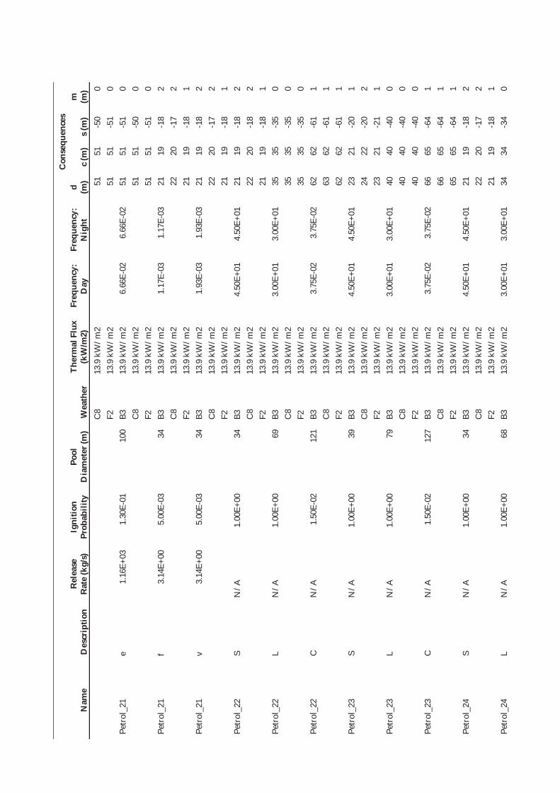
Nam
e D
escr
iptio
n R
elea
se
Rat
e (k
g/s)
Ig
nitio
n Pr
obab
ility
Po
ol
Dia
met
er (m
) W
eath
er
Ther
mal
Flu
x (k
W/m
2)
Freq
uenc
y:
Day
Fr
eque
ncy:
N
ight
Con
sequ
ence
s d (m
) c
(m)
s (m
) m
(m
) C
8 13
.9 k
W/m
2 51
51
-5
0 0
F2
13.9
kW
/m2
51
51
-51
0 Pe
trol
_21
e 1.
16E+
03
1.30
E-01
10
0 B3
13
.9 k
W/m
2 6.
66E-
02
6.66
E-02
51
51
-5
1 0
C8
13.9
kW
/m2
51
51
-50
0 F2
13
.9 k
W/m
2 51
51
-5
1 0
Petr
ol_2
1 f
3.14
E+00
5.
00E-
03
34
B3
13.9
kW
/m2
1.17
E-03
1.
17E-
03
21
19
-18
2 C
8 13
.9 k
W/m
2 22
20
-1
7 2
F2
13.9
kW
/m2
21
19
-18
1 Pe
trol
_21
v 3.
14E+
00
5.00
E-03
34
B3
13
.9 k
W/m
2 1.
93E-
03
1.93
E-03
21
19
-1
8 2
C8
13.9
kW
/m2
22
20
-17
2 F2
13
.9 k
W/m
2 21
19
-1
8 1
Petr
ol_2
2 S
N/A
1.
00E+
00
34
B3
13.9
kW
/m2
4.50
E+01
4.
50E+
01
21
19
-18
2 C
8 13
.9 k
W/m
2 22
20
-1
8 2
F2
13.9
kW
/m2
21
19
-18
1 Pe
trol
_22
L N
/A
1.00
E+00
69
B3
13
.9 k
W/m
2 3.
00E+
01
3.00
E+01
35
35
-3
5 0
C8
13.9
kW
/m2
35
35
-35
0 F2
13
.9 k
W/m
2 35
35
-3
5 0
Petr
ol_2
2 C
N
/A
1.50
E-02
12
1 B3
13
.9 k
W/m
2 3.
75E-
02
3.75
E-02
62
62
-6
1 1
C8
13.9
kW
/m2
63
62
-61
1 F2
13
.9 k
W/m
2 62
62
-6
1 1
Petr
ol_2
3 S
N/A
1.
00E+
00
39
B3
13.9
kW
/m2
4.50
E+01
4.
50E+
01
23
21
-20
1 C
8 13
.9 k
W/m
2 24
22
-2
0 2
F2
13.9
kW
/m2
23
21
-21
1 Pe
trol
_23
L N
/A
1.00
E+00
79
B3
13
.9 k
W/m
2 3.
00E+
01
3.00
E+01
40
40
-4
0 0
C8
13.9
kW
/m2
40
40
-40
0 F2
13
.9 k
W/m
2 40
40
-4
0 0
Petr
ol_2
3 C
N
/A
1.50
E-02
12
7 B3
13
.9 k
W/m
2 3.
75E-
02
3.75
E-02
66
65
-6
4 1
C8
13.9
kW
/m2
66
65
-64
1 F2
13
.9 k
W/m
2 65
65
-6
4 1
Petr
ol_2
4 S
N/A
1.
00E+
00
34
B3
13.9
kW
/m2
4.50
E+01
4.
50E+
01
21
19
-18
2 C
8 13
.9 k
W/m
2 22
20
-1
7 2
F2
13.9
kW
/m2
21
19
-18
1 Pe
trol
_24
L N
/A
1.00
E+00
68
B3
13
.9 k
W/m
2 3.
00E+
01
3.00
E+01
34
34
-3
4 0
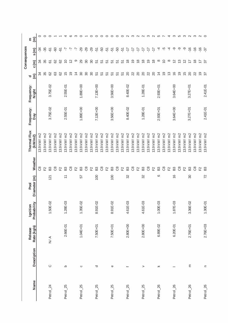
Nam
e D
escr
iptio
n R
elea
se
Rat
e (k
g/s)
Ig
nitio
n Pr
obab
ility
Po
ol
Dia
met
er (m
) W
eath
er
Ther
mal
Flu
x (k
W/m
2)
Freq
uenc
y:
Day
Fr
eque
ncy:
N
ight
Con
sequ
ence
s d (m
) c
(m)
s (m
) m
(m
) C
8 13
.9 k
W/m
2 34
34
-3
4 0
F2
13.9
kW
/m2
35
35
-35
0 Pe
trol
_24
C
N/A
1.
50E-
02
121
B3
13.9
kW
/m2
3.75
E-02
3.
75E-
02
62
61
-61
0 C
8 13
.9 k
W/m
2 63
62
-6
0 1
F2
13.9
kW
/m2
62
62
-61
1 Pe
trol
_25
b 2.
66E-
01
1.28
E-03
11
B3
13
.9 k
W/m
2 2.
55E-
01
2.55
E-01
15
10
-7
4
C8
13.9
kW
/m2
19
12
-7
6 F2
13
.9 k
W/m
2 14
9
-7
3 Pe
trol
_25
c 1.
04E+
01
1.35
E-02
57
B3
13
.9 k
W/m
2 1.
89E+
00
1.89
E+00
30
29
-2
9 0
C8
13.9
kW
/m2
30
30
-29
1 F2
13
.9 k
W/m
2 30
30
-2
9 0
Petr
ol_2
5 d
7.50
E+01
8.
91E-
02
100
B3
13.9
kW
/m2
7.13
E+00
7.
13E+
00
51
51
-51
0 C
8 13
.9 k
W/m
2 51
51
-5
0 0
F2
13.9
kW
/m2
51
51
-51
0 Pe
trol
_25
e 7.
50E+
01
8.91
E-02
10
0 B3
13
.9 k
W/m
2 3.
56E+
00
3.56
E+00
51
51
-5
1 0
C8
13.9
kW
/m2
51
51
-50
0 F2
13
.9 k
W/m
2 51
51
-5
1 0
Petr
ol_2
5 f
2.80
E+00
4.
61E-
03
32
B3
13.9
kW
/m2
8.40
E-02
8.
40E-
02
20
18
-17
2 C
8 13
.9 k
W/m
2 22
19
-1
7 3
F2
13.9
kW
/m2
20
18
-17
2 Pe
trol
_25
v 2.
80E+
00
4.61
E-03
32
B3
13
.9 k
W/m
2 1.
28E-
01
1.28
E-01
20
18
-1
7 2
C8
13.9
kW
/m2
22
19
-17
3 F2
13
.9 k
W/m
2 20
18
-1
7 2
Petr
ol_2
6 k
6.89
E-02
1.
00E-
03
6 B3
13
.9 k
W/m
2 2.
93E+
01
2.93
E+01
14
8
-4
5 C
8 13
.9 k
W/m
2 19
10
-5
7
F2
13.9
kW
/m2
13
8 -4
4
Petr
ol_2
6 l
6.20
E-01
1.
87E-
03
16
B3
13.9
kW
/m2
3.64
E+00
3.
64E+
00
16
12
-9
3 C
8 13
.9 k
W/m
2 19
13
-9
5
F2
13.9
kW
/m2
15
12
-9
3 Pe
trol
_26
m
2.76
E+01
3.
36E-
02
30
B3
13.9
kW
/m2
3.27
E+01
3.
27E+
01
20
17
-16
2 C
8 13
.9 k
W/m
2 22
18
-1
6 3
F2
13.9
kW
/m2
19
17
-16
2 Pe
trol
_26
n 2.
76E+
03
1.30
E-01
72
B3
13
.9 k
W/m
2 2.
41E-
01
2.41
E-01
37
37
-3
7 0

Nam
e D
escr
iptio
n R
elea
se
Rat
e (k
g/s)
Ig
nitio
n Pr
obab
ility
Po
ol
Dia
met
er (m
) W
eath
er
Ther
mal
Flu
x (k
W/m
2)
Freq
uenc
y:
Day
Fr
eque
ncy:
N
ight
Con
sequ
ence
s d (m
) c
(m)
s (m
) m
(m
) C
8 13
.9 k
W/m
2 37
37
-3
6 0
F2
13.9
kW
/m2
37
37
-37
0 Pe
trol
_27
b 2.
66E-
01
1.04
E-03
11
B3
13
.9 k
W/m
2 2.
07E-
02
2.07
E-02
15
10
-7
4
C8
13.9
kW
/m2
19
12
-7
6 F2
13
.9 k
W/m
2 14
9
-7
3 Pe
trol
_27
c 1.
04E+
01
3.78
E-03
28
B3
13
.9 k
W/m
2 4.
72E-
02
4.72
E-02
19
17
-1
5 2
C8
13.9
kW
/m2
21
17
-15
3 F2
13
.9 k
W/m
2 19
16
-1
5 2
Petr
ol_2
7 d
7.50
E+01
1.
50E-
02
28
B3
13.9
kW
/m2
7.50
E-02
7.
50E-
02
19
17
-15
2 C
8 13
.9 k
W/m
2 21
17
-1
5 3
F2
13.9
kW
/m2
19
16
-15
2 Pe
trol
_27
e 7.
50E+
01
1.50
E-02
28
B3
13
.9 k
W/m
2 2.
63E-
02
2.63
E-02
19
17
-1
5 2
C8
13.9
kW
/m2
21
17
-15
3 F2
13
.9 k
W/m
2 19
16
-1
5 2
Petr
ol_2
7 f
2.80
E+00
1.
68E-
03
28
B3
13.9
kW
/m2
5.11
E-03
5.
11E-
03
19
17
-15
2 C
8 13
.9 k
W/m
2 21
17
-1
5 3
F2
13.9
kW
/m2
19
16
-15
2 Pe
trol
_27
v 2.
80E+
00
1.68
E-03
28
B3
13
.9 k
W/m
2 1.
09E-
02
1.09
E-02
19
17
-1
5 2
C8
13.9
kW
/m2
21
17
-15
3 F2
13
.9 k
W/m
2 19
16
-1
5 2
Petr
ol_2
8 b
2.66
E-01
1.
04E-
03
11
B3
13.9
kW
/m2
2.59
E-02
2.
59E-
02
15
10
-7
4 C
8 13
.9 k
W/m
2 19
12
-7
6
F2
13.9
kW
/m2
14
9 -7
3
Petr
ol_2
8 c
1.04
E+01
3.
78E-
03
29
B3
13.9
kW
/m2
6.61
E-02
6.
61E-
02
19
17
-15
2 C
8 13
.9 k
W/m
2 21
18
-1
5 3
F2
13.9
kW
/m2
19
17
-16
2 Pe
trol
_28
d 7.
38E+
01
1.50
E-02
29
B3
13
.9 k
W/m
2 1.
50E-
01
1.50
E-01
19
17
-1
5 2
C8
13.9
kW
/m2
21
18
-15
3 F2
13
.9 k
W/m
2 19
17
-1
6 2
Petr
ol_2
8 e
7.50
E+01
1.
50E-
02
29
B3
13.9
kW
/m2
7.50
E-02
7.
50E-
02
19
17
-15
2 C
8 13
.9 k
W/m
2 21
18
-1
5 3
F2
13.9
kW
/m2
19
17
-16
2 Pe
trol
_28
f 2.
80E+
00
1.68
E-03
29
B3
13
.9 k
W/m
2 6.
59E-
03
6.59
E-03
19
17
-1
5 2

Nam
e D
escr
iptio
n R
elea
se
Rat
e (k
g/s)
Ig
nitio
n Pr
obab
ility
Po
ol
Dia
met
er (m
) W
eath
er
Ther
mal
Flu
x (k
W/m
2)
Freq
uenc
y:
Day
Fr
eque
ncy:
N
ight
Con
sequ
ence
s d (m
) c
(m)
s (m
) m
(m
) C
8 13
.9 k
W/m
2 21
18
-1
5 3
F2
13.9
kW
/m2
19
17
-16
2 Pe
trol
_28
v 2.
80E+
00
1.68
E-03
29
B3
13
.9 k
W/m
2 7.
73E-
03
7.73
E-03
19
17
-1
5 2
C8
13.9
kW
/m2
21
18
-15
3 F2
13
.9 k
W/m
2 19
17
-1
6 2
Petr
ol_2
9 b
2.66
E-01
1.
28E-
03
10
B3
13.9
kW
/m2
1.28
E-02
1.
28E-
02
15
10
-6
4 C
8 13
.9 k
W/m
2 19
12
-6
6
F2
13.9
kW
/m2
13
9 -6
4
Petr
ol_2
9 c
1.04
E+01
1.
35E-
02
10
B3
13.9
kW
/m2
9.43
E-02
9.
43E-
02
15
10
-6
4 C
8 13
.9 k
W/m
2 19
12
-6
6
F2
13.9
kW
/m2
13
9 -6
4
Petr
ol_2
9 d
7.38
E+01
8.
76E-
02
10
B3
13.9
kW
/m2
3.50
E-01
3.
50E-
01
15
10
-6
4 C
8 13
.9 k
W/m
2 19
12
-6
6
F2
13.9
kW
/m2
13
9 -6
4
Petr
ol_2
9 e
7.50
E+01
8.
91E-
02
10
B3
13.9
kW
/m2
1.78
E-01
1.
78E-
01
15
10
-6
4 C
8 13
.9 k
W/m
2 19
12
-6
6
F2
13.9
kW
/m2
13
9 -6
4
Petr
ol_2
9 p
7.50
E+01
8.
91E-
02
10
B3
13.9
kW
/m2
4.01
E+00
4.
01E+
00
15
10
-6
4 C
8 13
.9 k
W/m
2 19
12
-6
6
F2
13.9
kW
/m2
13
9 -6
4
Petr
ol_2
9 f
2.80
E+00
4.
61E-
03
10
B3
13.9
kW
/m2
8.03
E-03
8.
03E-
03
15
10
-6
4 C
8 13
.9 k
W/m
2 19
12
-6
6
F2
13.9
kW
/m2
13
9 -6
4
Petr
ol_2
9 v
2.80
E+00
4.
61E-
03
10
B3
13.9
kW
/m2
1.06
E-02
1.
06E-
02
15
10
-6
4 C
8 13
.9 k
W/m
2 19
12
-6
6
F2
13.9
kW
/m2
13
9 -6
4
Etha
nol_
30
k 4.
21E-
01
1.53
E-03
7
B3
13.9
kW
/m2
1.50
E+00
1.
50E+
00
14
8 -5
5
C8
13.9
kW
/m2
19
11
-5
7 F2
13
.9 k
W/m
2 13
8
-4
4 Et
hano
l_30
l
3.79
E+00
5.
76E-
03
7 B3
13
.9 k
W/m
2 3.
74E-
01
3.74
E-01
14
8
-5
5 C
8 13
.9 k
W/m
2 19
11
-5
7
F2
13.9
kW
/m2
13
8 -4
4
Etha
nol_
30
m
1.00
E+01
1.
30E-
02
7 B3
13
.9 k
W/m
2 8.
47E+
00
8.47
E+00
14
8
-5
5
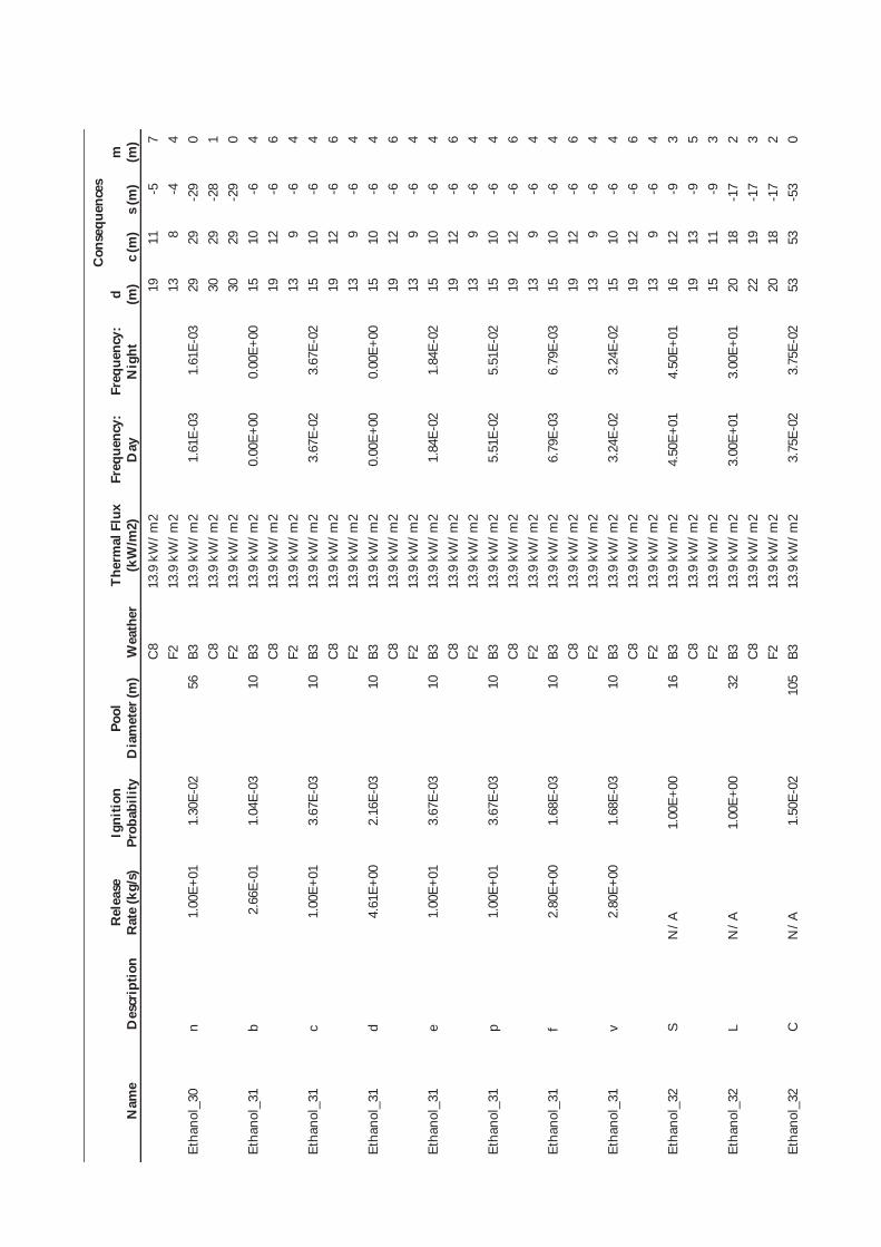
Nam
e D
escr
iptio
n R
elea
se
Rat
e (k
g/s)
Ig
nitio
n Pr
obab
ility
Po
ol
Dia
met
er (m
) W
eath
er
Ther
mal
Flu
x (k
W/m
2)
Freq
uenc
y:
Day
Fr
eque
ncy:
N
ight
Con
sequ
ence
s d (m
) c
(m)
s (m
) m
(m
) C
8 13
.9 k
W/m
2 19
11
-5
7
F2
13.9
kW
/m2
13
8 -4
4
Etha
nol_
30
n 1.
00E+
01
1.30
E-02
56
B3
13
.9 k
W/m
2 1.
61E-
03
1.61
E-03
29
29
-2
9 0
C8
13.9
kW
/m2
30
29
-28
1 F2
13
.9 k
W/m
2 30
29
-2
9 0
Etha
nol_
31
b 2.
66E-
01
1.04
E-03
10
B3
13
.9 k
W/m
2 0.
00E+
00
0.00
E+00
15
10
-6
4
C8
13.9
kW
/m2
19
12
-6
6 F2
13
.9 k
W/m
2 13
9
-6
4 Et
hano
l_31
c
1.00
E+01
3.
67E-
03
10
B3
13.9
kW
/m2
3.67
E-02
3.
67E-
02
15
10
-6
4 C
8 13
.9 k
W/m
2 19
12
-6
6
F2
13.9
kW
/m2
13
9 -6
4
Etha
nol_
31
d 4.
61E+
00
2.16
E-03
10
B3
13
.9 k
W/m
2 0.
00E+
00
0.00
E+00
15
10
-6
4
C8
13.9
kW
/m2
19
12
-6
6 F2
13
.9 k
W/m
2 13
9
-6
4 Et
hano
l_31
e
1.00
E+01
3.
67E-
03
10
B3
13.9
kW
/m2
1.84
E-02
1.
84E-
02
15
10
-6
4 C
8 13
.9 k
W/m
2 19
12
-6
6
F2
13.9
kW
/m2
13
9 -6
4
Etha
nol_
31
p 1.
00E+
01
3.67
E-03
10
B3
13
.9 k
W/m
2 5.
51E-
02
5.51
E-02
15
10
-6
4
C8
13.9
kW
/m2
19
12
-6
6 F2
13
.9 k
W/m
2 13
9
-6
4 Et
hano
l_31
f
2.80
E+00
1.
68E-
03
10
B3
13.9
kW
/m2
6.79
E-03
6.
79E-
03
15
10
-6
4 C
8 13
.9 k
W/m
2 19
12
-6
6
F2
13.9
kW
/m2
13
9 -6
4
Etha
nol_
31
v 2.
80E+
00
1.68
E-03
10
B3
13
.9 k
W/m
2 3.
24E-
02
3.24
E-02
15
10
-6
4
C8
13.9
kW
/m2
19
12
-6
6 F2
13
.9 k
W/m
2 13
9
-6
4 Et
hano
l_32
S
N/A
1.
00E+
00
16
B3
13.9
kW
/m2
4.50
E+01
4.
50E+
01
16
12
-9
3 C
8 13
.9 k
W/m
2 19
13
-9
5
F2
13.9
kW
/m2
15
11
-9
3 Et
hano
l_32
L
N/A
1.
00E+
00
32
B3
13.9
kW
/m2
3.00
E+01
3.
00E+
01
20
18
-17
2 C
8 13
.9 k
W/m
2 22
19
-1
7 3
F2
13.9
kW
/m2
20
18
-17
2 Et
hano
l_32
C
N
/A
1.50
E-02
10
5 B3
13
.9 k
W/m
2 3.
75E-
02
3.75
E-02
53
53
-5
3 0
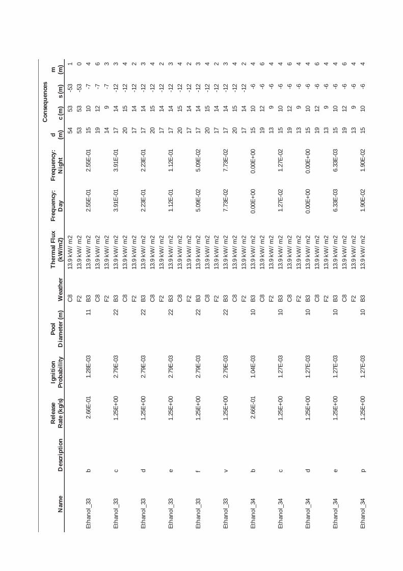
Nam
e D
escr
iptio
n R
elea
se
Rat
e (k
g/s)
Ig
nitio
n Pr
obab
ility
Po
ol
Dia
met
er (m
) W
eath
er
Ther
mal
Flu
x (k
W/m
2)
Freq
uenc
y:
Day
Fr
eque
ncy:
N
ight
Con
sequ
ence
s d (m
) c
(m)
s (m
) m
(m
) C
8 13
.9 k
W/m
2 54
53
-5
3 1
F2
13.9
kW
/m2
53
53
-53
0 Et
hano
l_33
b
2.66
E-01
1.
28E-
03
11
B3
13.9
kW
/m2
2.55
E-01
2.
55E-
01
15
10
-7
4 C
8 13
.9 k
W/m
2 19
12
-7
6
F2
13.9
kW
/m2
14
9 -7
3
Etha
nol_
33
c 1.
25E+
00
2.79
E-03
22
B3
13
.9 k
W/m
2 3.
91E-
01
3.91
E-01
17
14
-1
2 3
C8
13.9
kW
/m2
20
15
-12
4 F2
13
.9 k
W/m
2 17
14
-1
2 2
Etha
nol_
33
d 1.
25E+
00
2.79
E-03
22
B3
13
.9 k
W/m
2 2.
23E-
01
2.23
E-01
17
14
-1
2 3
C8
13.9
kW
/m2
20
15
-12
4 F2
13
.9 k
W/m
2 17
14
-1
2 2
Etha
nol_
33
e 1.
25E+
00
2.79
E-03
22
B3
13
.9 k
W/m
2 1.
12E-
01
1.12
E-01
17
14
-1
2 3
C8
13.9
kW
/m2
20
15
-12
4 F2
13
.9 k
W/m
2 17
14
-1
2 2
Etha
nol_
33
f 1.
25E+
00
2.79
E-03
22
B3
13
.9 k
W/m
2 5.
09E-
02
5.09
E-02
17
14
-1
2 3
C8
13.9
kW
/m2
20
15
-12
4 F2
13
.9 k
W/m
2 17
14
-1
2 2
Etha
nol_
33
v 1.
25E+
00
2.79
E-03
22
B3
13
.9 k
W/m
2 7.
73E-
02
7.73
E-02
17
14
-1
2 3
C8
13.9
kW
/m2
20
15
-12
4 F2
13
.9 k
W/m
2 17
14
-1
2 2
Etha
nol_
34
b 2.
66E-
01
1.04
E-03
10
B3
13
.9 k
W/m
2 0.
00E+
00
0.00
E+00
15
10
-6
4
C8
13.9
kW
/m2
19
12
-6
6 F2
13
.9 k
W/m
2 13
9
-6
4 Et
hano
l_34
c
1.25
E+00
1.
27E-
03
10
B3
13.9
kW
/m2
1.27
E-02
1.
27E-
02
15
10
-6
4 C
8 13
.9 k
W/m
2 19
12
-6
6
F2
13.9
kW
/m2
13
9 -6
4
Etha
nol_
34
d 1.
25E+
00
1.27
E-03
10
B3
13
.9 k
W/m
2 0.
00E+
00
0.00
E+00
15
10
-6
4
C8
13.9
kW
/m2
19
12
-6
6 F2
13
.9 k
W/m
2 13
9
-6
4 Et
hano
l_34
e
1.25
E+00
1.
27E-
03
10
B3
13.9
kW
/m2
6.33
E-03
6.
33E-
03
15
10
-6
4 C
8 13
.9 k
W/m
2 19
12
-6
6
F2
13.9
kW
/m2
13
9 -6
4
Etha
nol_
34
p 1.
25E+
00
1.27
E-03
10
B3
13
.9 k
W/m
2 1.
90E-
02
1.90
E-02
15
10
-6
4
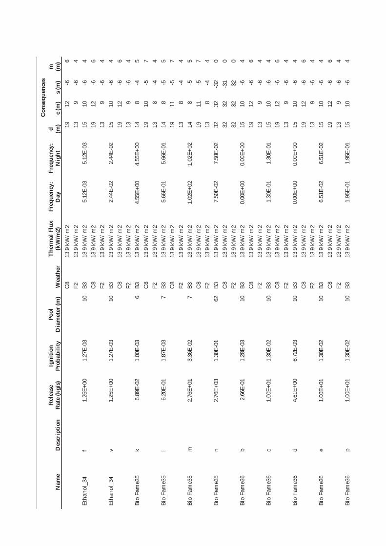
Nam
e D
escr
iptio
n R
elea
se
Rat
e (k
g/s)
Ig
nitio
n Pr
obab
ility
Po
ol
Dia
met
er (m
) W
eath
er
Ther
mal
Flu
x (k
W/m
2)
Freq
uenc
y:
Day
Fr
eque
ncy:
N
ight
Con
sequ
ence
s d (m
) c
(m)
s (m
) m
(m
) C
8 13
.9 k
W/m
2 19
12
-6
6
F2
13.9
kW
/m2
13
9 -6
4
Etha
nol_
34
f 1.
25E+
00
1.27
E-03
10
B3
13
.9 k
W/m
2 5.
12E-
03
5.12
E-03
15
10
-6
4
C8
13.9
kW
/m2
19
12
-6
6 F2
13
.9 k
W/m
2 13
9
-6
4 Et
hano
l_34
v
1.25
E+00
1.
27E-
03
10
B3
13.9
kW
/m2
2.44
E-02
2.
44E-
02
15
10
-6
4 C
8 13
.9 k
W/m
2 19
12
-6
6
F2
13.9
kW
/m2
13
9 -6
4
Bio
Fam
e35
k 6.
89E-
02
1.00
E-03
6
B3
13.9
kW
/m2
4.55
E+00
4.
55E+
00
14
8 -4
5
C8
13.9
kW
/m2
19
10
-5
7 F2
13
.9 k
W/m
2 13
8
-4
4 Bi
o Fa
me3
5 l
6.20
E-01
1.
87E-
03
7 B3
13
.9 k
W/m
2 5.
66E-
01
5.66
E-01
14
8
-5
5 C
8 13
.9 k
W/m
2 19
11
-5
7
F2
13.9
kW
/m2
13
8 -4
4
Bio
Fam
e35
m
2.76
E+01
3.
36E-
02
7 B3
13
.9 k
W/m
2 1.
02E+
02
1.02
E+02
14
8
-5
5 C
8 13
.9 k
W/m
2 19
11
-5
7
F2
13.9
kW
/m2
13
8 -4
4
Bio
Fam
e35
n 2.
76E+
03
1.30
E-01
62
B3
13
.9 k
W/m
2 7.
50E-
02
7.50
E-02
32
32
-3
2 0
C8
13.9
kW
/m2
32
32
-31
0 F2
13
.9 k
W/m
2 32
32
-3
2 0
Bio
Fam
e36
b 2.
66E-
01
1.28
E-03
10
B3
13
.9 k
W/m
2 0.
00E+
00
0.00
E+00
15
10
-6
4
C8
13.9
kW
/m2
19
12
-6
6 F2
13
.9 k
W/m
2 13
9
-6
4 Bi
o Fa
me3
6 c
1.00
E+01
1.
30E-
02
10
B3
13.9
kW
/m2
1.30
E-01
1.
30E-
01
15
10
-6
4 C
8 13
.9 k
W/m
2 19
12
-6
6
F2
13.9
kW
/m2
13
9 -6
4
Bio
Fam
e36
d 4.
61E+
00
6.72
E-03
10
B3
13
.9 k
W/m
2 0.
00E+
00
0.00
E+00
15
10
-6
4
C8
13.9
kW
/m2
19
12
-6
6 F2
13
.9 k
W/m
2 13
9
-6
4 Bi
o Fa
me3
6 e
1.00
E+01
1.
30E-
02
10
B3
13.9
kW
/m2
6.51
E-02
6.
51E-
02
15
10
-6
4 C
8 13
.9 k
W/m
2 19
12
-6
6
F2
13.9
kW
/m2
13
9 -6
4
Bio
Fam
e36
p 1.
00E+
01
1.30
E-02
10
B3
13
.9 k
W/m
2 1.
95E-
01
1.95
E-01
15
10
-6
4
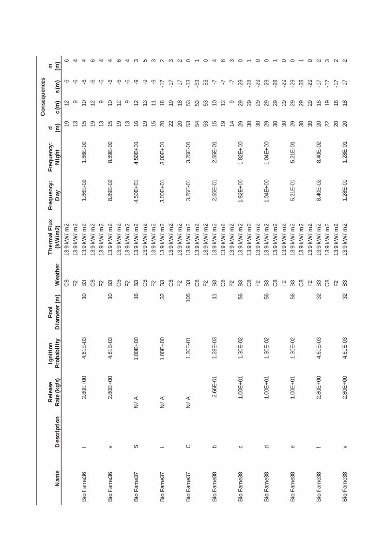
Nam
e D
escr
iptio
n R
elea
se
Rat
e (k
g/s)
Ig
nitio
n Pr
obab
ility
Po
ol
Dia
met
er (m
) W
eath
er
Ther
mal
Flu
x (k
W/m
2)
Freq
uenc
y:
Day
Fr
eque
ncy:
N
ight
Con
sequ
ence
s d (m
) c
(m)
s (m
) m
(m
) C
8 13
.9 k
W/m
2 19
12
-6
6
F2
13.9
kW
/m2
13
9 -6
4
Bio
Fam
e36
f 2.
80E+
00
4.61
E-03
10
B3
13
.9 k
W/m
2 1.
86E-
02
1.86
E-02
15
10
-6
4
C8
13.9
kW
/m2
19
12
-6
6 F2
13
.9 k
W/m
2 13
9
-6
4 Bi
o Fa
me3
6 v
2.80
E+00
4.
61E-
03
10
B3
13.9
kW
/m2
8.89
E-02
8.
89E-
02
15
10
-6
4 C
8 13
.9 k
W/m
2 19
12
-6
6
F2
13.9
kW
/m2
13
9 -6
4
Bio
Fam
e37
S N
/A
1.00
E+00
16
B3
13
.9 k
W/m
2 4.
50E+
01
4.50
E+01
16
12
-9
3
C8
13.9
kW
/m2
19
13
-9
5 F2
13
.9 k
W/m
2 15
11
-9
3
Bio
Fam
e37
L N
/A
1.00
E+00
32
B3
13
.9 k
W/m
2 3.
00E+
01
3.00
E+01
20
18
-1
7 2
C8
13.9
kW
/m2
22
19
-17
3 F2
13
.9 k
W/m
2 20
18
-1
7 2
Bio
Fam
e37
C
N/A
1.
30E-
01
105
B3
13.9
kW
/m2
3.25
E-01
3.
25E-
01
53
53
-53
0 C
8 13
.9 k
W/m
2 54
53
-5
3 1
F2
13.9
kW
/m2
53
53
-53
0 Bi
o Fa
me3
8 b
2.66
E-01
1.
28E-
03
11
B3
13.9
kW
/m2
2.55
E-01
2.
55E-
01
15
10
-7
4 C
8 13
.9 k
W/m
2 19
12
-7
6
F2
13.9
kW
/m2
14
9 -7
3
Bio
Fam
e38
c 1.
00E+
01
1.30
E-02
56
B3
13
.9 k
W/m
2 1.
82E+
00
1.82
E+00
29
29
-2
9 0
C8
13.9
kW
/m2
30
29
-28
1 F2
13
.9 k
W/m
2 30
29
-2
9 0
Bio
Fam
e38
d 1.
00E+
01
1.30
E-02
56
B3
13
.9 k
W/m
2 1.
04E+
00
1.04
E+00
29
29
-2
9 0
C8
13.9
kW
/m2
30
29
-28
1 F2
13
.9 k
W/m
2 30
29
-2
9 0
Bio
Fam
e38
e 1.
00E+
01
1.30
E-02
56
B3
13
.9 k
W/m
2 5.
21E-
01
5.21
E-01
29
29
-2
9 0
C8
13.9
kW
/m2
30
29
-28
1 F2
13
.9 k
W/m
2 30
29
-2
9 0
Bio
Fam
e38
f 2.
80E+
00
4.61
E-03
32
B3
13
.9 k
W/m
2 8.
40E-
02
8.40
E-02
20
18
-1
7 2
C8
13.9
kW
/m2
22
19
-17
3 F2
13
.9 k
W/m
2 20
18
-1
7 2
Bio
Fam
e38
v 2.
80E+
00
4.61
E-03
32
B3
13
.9 k
W/m
2 1.
28E-
01
1.28
E-01
20
18
-1
7 2
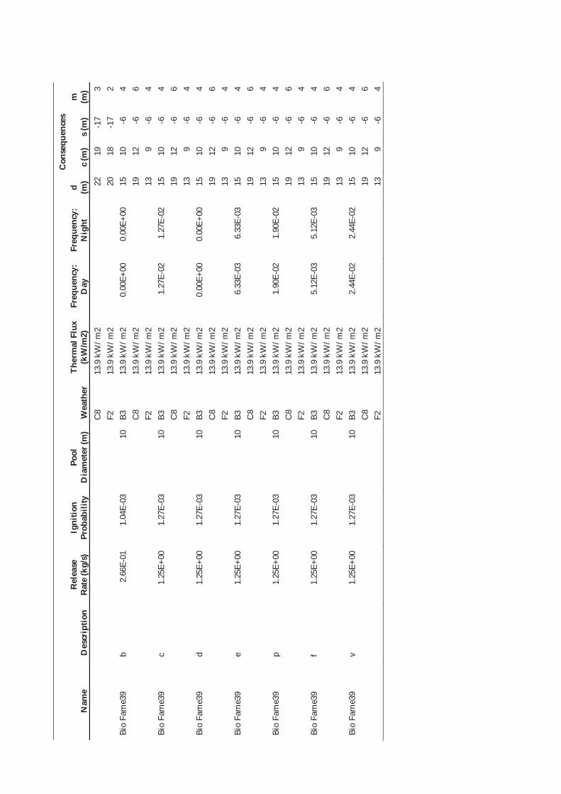
Nam
e D
escr
iptio
n R
elea
se
Rat
e (k
g/s)
Ig
nitio
n Pr
obab
ility
Po
ol
Dia
met
er (m
) W
eath
er
Ther
mal
Flu
x (k
W/m
2)
Freq
uenc
y:
Day
Fr
eque
ncy:
N
ight
Con
sequ
ence
s d (m
) c
(m)
s (m
) m
(m
) C
8 13
.9 k
W/m
2 22
19
-1
7 3
F2
13.9
kW
/m2
20
18
-17
2 Bi
o Fa
me3
9 b
2.66
E-01
1.
04E-
03
10
B3
13.9
kW
/m2
0.00
E+00
0.
00E+
00
15
10
-6
4 C
8 13
.9 k
W/m
2 19
12
-6
6
F2
13.9
kW
/m2
13
9 -6
4
Bio
Fam
e39
c 1.
25E+
00
1.27
E-03
10
B3
13
.9 k
W/m
2 1.
27E-
02
1.27
E-02
15
10
-6
4
C8
13.9
kW
/m2
19
12
-6
6 F2
13
.9 k
W/m
2 13
9
-6
4 Bi
o Fa
me3
9 d
1.25
E+00
1.
27E-
03
10
B3
13.9
kW
/m2
0.00
E+00
0.
00E+
00
15
10
-6
4 C
8 13
.9 k
W/m
2 19
12
-6
6
F2
13.9
kW
/m2
13
9 -6
4
Bio
Fam
e39
e 1.
25E+
00
1.27
E-03
10
B3
13
.9 k
W/m
2 6.
33E-
03
6.33
E-03
15
10
-6
4
C8
13.9
kW
/m2
19
12
-6
6 F2
13
.9 k
W/m
2 13
9
-6
4 Bi
o Fa
me3
9 p
1.25
E+00
1.
27E-
03
10
B3
13.9
kW
/m2
1.90
E-02
1.
90E-
02
15
10
-6
4 C
8 13
.9 k
W/m
2 19
12
-6
6
F2
13.9
kW
/m2
13
9 -6
4
Bio
Fam
e39
f 1.
25E+
00
1.27
E-03
10
B3
13
.9 k
W/m
2 5.
12E-
03
5.12
E-03
15
10
-6
4
C8
13.9
kW
/m2
19
12
-6
6 F2
13
.9 k
W/m
2 13
9
-6
4 Bi
o Fa
me3
9 v
1.25
E+00
1.
27E-
03
10
B3
13.9
kW
/m2
2.44
E-02
2.
44E-
02
15
10
-6
4 C
8 13
.9 k
W/m
2 19
12
-6
6
F2
13.9
kW
/m2
13
9 -6
4

Ta
ble
D.4
Bu
ncef
ield
Sce
nari
o M
odel
ling
Res
ults
Nam
e D
escr
iptio
n W
eath
er
Endp
oint
Cri
teri
a
Freq
uenc
y:
Day
(cpm
) Fr
eque
ncy:
N
ight
(cpm
) C
onse
quen
ces
d (m
) c
(m)
s (m
) m
(m)
Tank
85
6,13
19,1
444
Larg
e Fl
ash
Fire
B3
LF
L 6.
14E-
03
1.49
E-02
0
0 0
0 C
8 LF
L 0
0 0
0 F2
LF
L 47
0 13
5 0
235
Tank
85
6,13
19,1
444
Vap
our C
loud
Exp
losi
on
B3
250
mba
r 6.
14E-
03
1.49
E-02
0
0 0
0 C
8 25
0 m
bar
0 0
0 0
F2
250
mba
r 40
0 40
0 -4
00
0 B3
2
bar
0 0
0 0
C8
2 ba
r 0
0 0
0 F2
2
bar
250
250
-250
0
Tank
85
6,13
19,1
444
Smal
l Fla
sh F
ire
– no
t cal
m
B3
0.5L
FL
8.48
E-01
8.
48E-
01
20
16
-1
14
C8
0.5L
FL
220
27.5
0
107
B3
LFL
15
14
-1
12
C8
LFL
140
17.5
0
76
Tank
85
6,13
19,1
444
Smal
l Fla
sh F
ire
– ca
lm
F2
0.5L
FL
8.44
E-01
7.
98E-
01
33
24
0 10
0 F2
LF
L
29
19
0
81

Fuels Safety Data Sheet
Issued: 11 March 2003
SDS No. DMC04005 DIESOLINE
1. IDENTIFICATION OF THE SUBSTANCE/PREPARATION AND COMPANY
Product name: DiesolineProduct code: (To be provided by the supplier)Product type: Fuel for on-road diesel-powered engines.Supplier: Shell SA (Pty) LtdAddress: PO Box 2231
Cape Town 8000Contact numbers:Telephone:Fax:
021 408 4911021 419 2864
Emergency telephone number:
Priority Action Line 011 608 3300
2. COMPOSITION/INFORMATION ON INGREDIENTS
Synonyms: Diesel, AGO, Automotive Gas OilPreparation description: Complex mixture of hydrocarbons consisting of paraffins, cycloparaffins,
aromatic and olefinic hydrocarbons with carbon numbers predominantly in the C10 to C22 range. May contain catalytically cracked oils in which polycyclic aromatic compounds, mainly 3-ring but some 4- to 6-ring species, are present. It may also contain one or more of the following additives: anti-oxidants, corrosion inhibitors, biocides, dyes, markers, proprietary performance improving additives.
Dangerous components/constituents:
Component name CAS number Content range EC hazard R phrases
Fuels, diesel 68334-30-5 >99 %(m/m) Carc Cat 3 R40-65-52/53Note: EU Dangerous Substances Directive, 67/548/EEC, Annex I number for the above substance is 649-224-00-6.
Contains the following substances for which exposure limits apply: No ACGIH limits established.
3. HAZARDS IDENTIFICATION
Human health hazards:
Possible risks of irreversible effects. Product classified as a Category 3 carcinogen. Harmful: may cause lung damage if swallowed. Aspiration into the lungs may cause chemical pneumonitis which can be fatal. Prolonged/repeated contact may cause defatting of the skin which can lead to dermatitis. Under conditions of poor personal hygiene, excessive exposure may lead to irritation, oil acne and folliculitis and development of warty growths which may subsequently become malignant. Prolonged exposure to vapour concentrations may affect the central nervous system.

Safety hazards:
Not classified as flammable, but will burn.
Environmental hazards:
Harmful to aquatic organisms. May cause long term adverse effects in the environment. Large volumes may penetrate soil and could contaminate groundwater. Not readily biodegradable. Has the potential to bioaccumulate. Persists under anaerobic conditions.
4. FIRST AID MEASURES
Symptoms and effects: Splashes into the eye may cause irritation. If ingested can lead to irritation of the mouth, irritation of the throat, irritation of the digestive tract,vomiting. Aspiration into the lungs may occur directly or following ingestion. This can cause chemical pneumonitis which may be fatal. Prolonged exposure to vapour/mist concentrations above the recommended occupational exposure standard may cause: headache, dizziness, nausea, irritation of the eyes, upper respiratory tract, mouth, and digestive tract, cardiac irregularities, asphyxiation, unconsciousness and even death.
First Aid - Inhalation: Remove to fresh air. If breathing but unconscious, place in the recovery position. If breathing has stopped, apply artificial respiration. If heartbeat absent give external cardiac compression. Monitor breathing and pulse. OBTAIN MEDICAL ATTENTION IMMEDIATELY.
First Aid - Skin: Wash skin with water using soap if available. Contaminated clothing must be removed as soon as possible. It must be laundered before reuse.
First Aid - Eye: Flush eye with water. If persistent irritation occurs, obtain medical attention.
First Aid - Ingestion: DO NOT DELAY. Do not induce vomiting. Protect the airway if vomiting begins. Give nothing by mouth. If breathing but unconscious, place in the recovery position. If breathing has stopped, apply artificial respiration. OBTAIN MEDICAL ATTENTION IMMEDIATELY.
Advice to physicians: Treat symptomatically. Diagnosis of ingestion of this product is by the characteristic odour on the victim's breath and from the history of events. In cases of ingestion, consider gastric lavage. Gastric lavage must only be undertaken after cuffed endotracheal intubation in view of the risk of aspiration. In cases of chemical pneumonitis, antibiotic and corticosteroid therapy should be considered. Administration of medicinal liquid paraffin or carbon for medicinal use (carbo medicalis) may reduce absorption fromthe digestive tract.
5. FIRE FIGHTING MEASURES
Specific hazards: Hazardous combustion products may include: carbon monoxide, oxides of nitrogen, oxides of sulphur, unburnt hydrocarbons.
Extinguishing media: Foam, water spray or fog. Dry chemical powder, carbon dioxide, sand or earth may be used for small fires only.
Unsuitable extinguishing media:
Water in a jet. Use of Halon extinguishers should be avoided for environmental reasons.
Other information: Keep adjacent drums and tanks cool by spraying with water.

6. ACCIDENTAL RELEASE MEASURES
Personal precautions: Remove all possible sources of ignition in the surrounding area and evacuate all personnel. Do not breathe: vapour, mists. Avoid contact with: skin, eyes and clothing. Take off immediately all contaminated clothing.
Personal protection: Wear: impervious overalls, PVC or nitrile rubber gloves, safety shoes or boots - chemical resistant, monogoggles.
Environmental precautions: Prevent from entering into drains, ditches or rivers. Use appropriate containment to avoid environmental contamination.
Clean-up methods - small spillage:
Absorb or contain liquid with sand, earth or spill control material. Shovel up and place in a labelled sealable container for subsequent safe disposal. Do not disperse using water.
Clean-up methods - large spillage:
Transfer to a labelled, sealable container for product recovery or safe disposal. Otherwise treat as for small spillage.
Other information: Local authorities should be advised if significant spillages cannot be contained. Observe all relevant local regulations. See Section 13 for information on disposal.
7. HANDLING AND STORAGE
Handling: When using do not eat, drink or smoke. Only use in well-ventilated areas. Take precautionary measures against static discharges. Earth or bond all equipment.
Handling temperature:
Ambient.
Storage: Locate tanks away from heat and other sources of ignition. This product must never be stored in buildings occupied by people. Small volumes may be stored in a suitably designed portable container. Such containers should be stored in well-ventilated areas, flameproof cabinets or stores. Do not store in unsuitable, unlabelled or incorrectly labelled containers. Keep container tightly closed in a dry, well-ventilated place away from direct sunlight and other sources of heat or ignition. Keep in a bunded area. Prevent ingress of water. Drums should be correctly stacked to a maximum of 3 high. Keep out of reach of children.
Storage temperature:
Ambient.
Product transfer:
Electrostatic charges may be generated during pumping. Ensure electrical continuity by bonding all equipment. Avoid splash filling. Particular care must be taken when 'switch loading' road/rail tankers which have previously contained gasoline. Wait 10 minutes after tank filling before opening hatches or manholes.
Tank cleaning: Cleaning, inspection and maintenance of storage tanks is a specialist operation which requires the implementation of strict procedures and precautions. These include issuing of work permits, gas-freeing of tanks, using a manned harness and lifelines and wearing air-supplied breathing apparatus. Prior to entry and whilst cleaning is underway, the atmosphere within the tank must be monitored using an oxygen meter and/or explosimeter. Additional precautions are required where the tank may in the past have contained leaded gasoline. Consult the Associated Octel Company publication 'Leaded Gasoline Tanks - Cleaning and Disposal of Sludge'.
Recommended materials:
For containers, use: mild steel, stainless steel. Aluminium may also be used for applications where it does not present an unnecessary fire hazard. For container linings, use: amine-adduct cured epoxy paint. For seals and gaskets, use: compressed asbestos fibre, PTFE, Viton A, Viton B .

Unsuitable materials:
Examples of materials to avoid in the construction of facilities for the storage, handling and distribution of this product are: copper, copper alloys (ferrous and non-ferrous), zinc, zinc alloys. Synthetic materials such as plastics and fibreglass may also be unsuitable, depending on the material specification and intended use. Materials for packages, containers (including containers for the retention or despatch of samples) and container linings must not adversely affect the quality of the product. They must be impermeable and must not be weakened or otherwise affected by the product. Examples of materials to avoid are: natural rubber, polymethyl methacrylate, polystyrene, polyvinyl chloride, polyisobutylene. Polyethylene and polypropylene are also unsuitable unless they are high density types which have been specifically tested for compatibility with this product.
Other information:
Ensure that all local regulations regarding handling and storage facilities are followed. Never siphon by mouth.
8. EXPOSURE CONTROLS/PERSONAL PROTECTION
Occupational exposure standards:
None established.
Respiratory protection: Not normally required. In a confined space self-contained breathing apparatus may be required.
Hand protection: PVC or nitrile rubber gloves if splashes are likely to occur.Eye protection: Monogoggles if splashes are likely to occur.Body protection: Wear overalls to minimise contamination of personal clothing. Launder
overalls and undergarments regularly. Safety shoes or boots - chemical resistant.
9. PHYSICAL AND CHEMICAL PROPERTIES
Physical state: Liquid at ambient temperatureColour: (To be provided by the supplier)Odour: CharacteristicInitial boiling point: circa 150°CFinal boiling point: circa 390°CVapour pressure: <0.5 kPa at 40°CDensity: 800-900 kg/m³ at 15°CKinematic viscosity: 2-7 mm²/s at 40°CVapour density (air=1): > 5Pour point: (To be provided by the supplier)Flash point: > 56°C (PMCC)Flammability limit - lower: circa 1 %(V/V)Flammability limit - upper: circa 6 %(V/V)Auto-ignition temperature: > 250 °CExplosive properties: In use, may form flammable/explosive vapour-air mixtureOxidizing properties: NoneSolubility in water: Data not availablen-octanol/water partition coefficient:
log Pow = 3-7
Evaporation rate: Data not available

10. STABILITY/REACTIVITY
Stability: Stable.Conditions to avoid: Heat, flames and sparks.Materials to avoid: Strong oxidizing agents.Hazardous decomposition products:
None known.
11. TOXICOLOGICAL INFORMATION
Basis for assessment: Toxicological data have not been determined specifically for this product. Information given is based on a knowledge of the toxicology ofsimilar products.
Acute toxicity - oral: LD50 >5000 mg/kg.Acute toxicity - dermal: LD50 >2000 mg/kg.Acute toxicity - inhalation: LC50 >5 mg/l.Eye irritation: Expected to be slightly irritant.Skin irritation: Expected to be slightly irritant.Respiratory irritation: Data not available from animal studies.Skin sensitization: Not expected to be a skin sensitizer.(Sub) chronic toxicity: Repeated skin exposure expected to cause moderate to severe
irritation. Repeated inhalation of mists expected to cause irritation of the respiratory tract.
Carcinogenicity: Dermal application to mice causes skin tumours.Mutagenicity: Not considered to be a mutagenic hazard.Reproductive toxicity: Does not impair fertility. Not a developmental toxicant.Human effects: Prolonged/repeated contact may cause defatting of the skin which can
lead to dermatitis. Under conditions of poor personal hygiene, excessive exposure may lead to irritation, oil acne and folliculitis and development of warty growths which may subsequently become malignant. See Section 4 for information regarding acute effects to humans.
12. ECOLOGICAL INFORMATION
Basis for assessment: Ecotoxicological data have not been determined specifically for this product. Information given is based on a knowledge of the ecotoxicology of similar products.
Mobility: Floats on water. Partly evaporates from water or soil surfaces, but a significant proportion will remain after one day. Large volumes may penetrate soil and could contaminate groundwater.
Persistence/degradability: Not readily biodegradable. Persists under anaerobic conditions. Oxidizes rapidly by photochemical reactions in air.
Bioaccumulation: Has the potential to bioaccumulate. May cause tainting of fish and shellfish.
Ecotoxicity: Poorly soluble mixture. Harmful, 10 < LC/EC50 < 100 mg/l, to aquatic organisms. (LC/EC50 expressed as the nominal amount of product required to prepare aqueous test extract). Low acute toxicity to mammals. May cause physical fouling of aquatic organisms.
Sewage treatment: Product is expected to be harmful, EC50 >10-100 mg/l, to organisms in sewage treatment plants. (EC50 expressed as the nominal amount of product required to prepare aqueous test extract).
Other information: This product is a preparation. The EC has not yet defined criteria for classifying preparations as dangerous for the environment. However, the refinery streams which constitute > 99 %(m/m) of this product meet the criteria for classification as dangerous for the environment, with the following Risk phrases: R52/53 - Harmful to aquatic organisms, may cause long-term adverse effects in the aquatic environment.
13. DISPOSAL CONSIDERATIONS
Precautions: See Section 8.Waste disposal: Waste arising from a spillage or tank cleaning should be disposed of in
accordance with prevailing regulations, preferably to a recognised collector or contractor. The competence of the collector or contractor should be established beforehand. Do not dispose into the environment, in drains or in water courses.
Product disposal:
Container disposal: 200 litre drums should be emptied and returned to the supplier or sent to a drum conditioner without removing or defacing markings or labels. Drums should not be reused without first obliterating all markings.
Local legislation: (To be provided by the supplier)
14. TRANSPORT INFORMATION
UN Number: 1202UN Class/Packing Group: 3, IIIUN Proper Shipping Name: Gas oil or Diesel fuelUN Number (sea transport, IMO): 1202IMO Class/Packing Group: 3.3, IIIIMO Symbol: Flammable LiquidIMO Marine Pollutant: NoIMO Proper Shipping Name: Gas oil or Diesel fuelADR/RID Class/Item: 3, 31° (c)ADR/RID Symbol: Flammable LiquidADR/RID Kemler Number: 30-1202ADR/RID Proper Shipping Name: Gas oil or Diesel fuelADNR Class/Item: (To be provided by the supplier)UN Number (air transport, ICAO): 1202IATA/ICAO Class/Packing Group: 3, IIIIATA/ICAO Symbol: Flammable LiquidIATA/ICAO Proper Shipping Name: Gas oil or Diesel FuelHazchem code: 3Z

15. REGULATORY INFORMATION
EC Label name: Contains: gas oil - unspecifiedEC Classification: Carcinogenic, category 3
HarmfulEC Symbols: XnEC Risk Phrases: R40 Possible risks of irreversible effects
R65 Harmful: may cause lung damage if swallowedEC Safety Phrases: S2 Keep out of reach of children.
S24 Avoid contact with skin.S36/37 Wear suitable protective clothing and gloves.S43 In case of fire use foam/dry powder/CO2 - Never use waterS62 If swallowed, do not induce vomiting: seek medical advice
immediately and show this container or label.EINECS (EC): All components listed.National legislation: (To be provided by the supplier)Other information: (To be provided by the supplier)
16. OTHER INFORMATION
Uses and restrictions: Fuel for on-road diesel-powered engines. This product must not be used in applications other than the above without first seeking the advice of the supplier. This product is not to be used: as a solvent or cleaning agent; for lighting or brightening fires; as a skin cleanser.
Technical contact point: Mr JJ SiemelinkTechnical contact number:
Telephone:Fax:
021 408 4485021 419 4781
SDS history: Edition number: 3First issued: June 1, 1993 Previous revisions: April 10, 1996Revised: September 24, 1996
Revisions highlighted: Sections 2, 3 and 15: classification and labelling for the aspiration hazard revised in line with the 22nd ATP to the EU Dangerous Substances Directive.Sections 2, 3 and 12: recommended CONCAWE environmental classification for gas oil added.Sections 3 and 5: Comment on distant ignition of vapour deleted.Section 3, 4, 6, 7 and 11: Editorial changes.Section 8: OEL for oil mist deleted.Section 15: error in EC Classification corrected. Changes indicated by vertical line to left of text.
SDS distribution: This document contains important information to ensure the safe storage, handling and use of this product. The information in this document should be brought to the attention of the person in your organisation responsible for advising on safety matters.
Other information: (To be provided by the supplier)

References: Useful references include the following: The Institute of Petroleum, London, 'Marketing Safety Code', Heyden and Son Limited, 1978 Applied Science, London, 'European Model Code of Safe Practice in the Storage and Handling of Petroleum Products Part 1: Operations', 1973.CONCAWE, Brussels. 'Gas Oils (diesel fuels/heating oils)' Product Dossier No 96/107.Associated Octel Company, 'Leaded gasoline tanks - cleaning and disposal of sludge'.
This information is based on our current knowledge and is intended to describe the product for the purposes of health, safety and environmental requirements only. It should not be construed as guaranteeing any specific property of the product.

Fuels Safety Data SheetIssued: 16 April 1997
SDS No. DMC04002 ULTRA DETERGENT PETROL
1. IDENTIFICATION OF THE SUBSTANCE/PREPARATION AND COMPANY
Product name: Ultra Detergent Petrol
Product code: (To be provided by the supplier)
Product type: Fuel for spark ignition internal combustion engines designed to run on leaded fuel.
Supplier: Shell SA (Pty) Ltd
Address: PO Box 2231Cape Town 8000
Contact numbers:
Telephone:Fax:
021 408 4911021 419 2864
Emergency telephone number:
Priority Action Line 011 608 3300
2. COMPOSITION/INFORMATION ON INGREDIENTS
Synonyms: Motor Gasoline, Motor Spirit, Petrol, Benzine
Preparation description: Complex mixture of hydrocarbons consisting of paraffins, cycloparaffins, aromatic and olefinic hydrocarbons with carbon numbers predominantly in the C4 to C12 range.Benzene may be present in concentrations up to 5 %(V/V). n-Hexane may be present in concentrations up to 5 %(V/V). Contains lead alkyl anti-knock additives. Maximum lead concentration: (<0.36) g/l. (To be provided by the supplier) It may also contain one or more of the following additives: anti-oxidants, corrosion inhibitors, metal deactivators, carburettor anti-icing compounds, dyes, markers, proprietary performance improving packages.
Dangerous components/constituents:
Component name CAS number Content range EC hazard R phrases
Gasoline 86290-81-5 >99%(V/V) F+, Carc Cat 2, Xn
R12-45-65-38-52/53
Benzene 71-43-2 < 5 %(V/V) F, Carc Cat 1,T R11-45-48/23/24/25Note: EU Dangerous Substances Directive, 67/548/EEC, Annex I numbers for the above substances are 649-378-00-4 and 601-020-00-8 respectively
Contains the following substances for which exposure limits apply: gasoline, n-hexane, benzene, toluene, xylene, tetramethyl lead, tetraethyl lead.

3. HAZARDS IDENTIFICATION
Human health hazards: May cause cancer. Product classified as Category 2 carcinogen. Harmful: may cause lung damage if swallowed. Aspiration into the lungs may cause chemical pneumonitis which can be fatal. Irritating to skin. Prolonged/repeated contact may cause defatting of the skin which can lead to dermatitis. Prolonged exposure to vapour concentrations may affect the central nervous system.
This product contains benzene which is known to cause leukaemia, organic lead which may cause long-term effects and n-hexane which is neuropathic.
Safety hazards: Extremely flammable. Will float and can be reignited on surface water. The vapour is heavier than air, spreads along the ground and distant ignition is possible.
Environmental hazards: Harmful to aquatic organisms. May cause long term adverse effects in the environment. Large volumes may penetrate soil and could contaminate groundwater. Not readily biodegradable. Has the potential to bioaccumulate. Persists under anaerobic conditions.
4. FIRST AID MEASURES
Symptoms and effects: Splashes into the eye may cause a transient irritation. If ingested can lead to irritation of the digestive tract, diarrhoea, vomiting. Aspiration into the lungs may occur directly or following ingestion. This can cause chemical pneumonitis which may be fatal. Prolonged exposure to vapour concentrations above the recommended occupational exposure standard may cause: impairment of judgement, headache, dizziness, nausea, irritation of the eyes and upper respiratory tract, cardiac irregularities, convulsions, asphyxiation, unconsciousness and even death.
First Aid - Inhalation: Remove to fresh air. If breathing but unconscious, place in the recovery position. If breathing has stopped, apply artificial respiration. If heartbeat absent give external cardiac compression. Monitor breathing and pulse. OBTAIN MEDICAL ATTENTION IMMEDIATELY.
First Aid - Skin: Wash skin with water using soap if available. Note that contaminated clothing may be a fire hazard. Contaminated clothing should be soaked with water before being removed. It must be laundered before reuse.
First Aid - Eye: Flush eye with water. If persistent irritation occurs, obtain medical attention.
First Aid - Ingestion: DO NOT DELAY. Do not induce vomiting. Protect the airway if vomiting begins. Give nothing by mouth. If breathing but unconscious, place in the recovery position. If breathing has stopped, apply artificial respiration. OBTAIN MEDICAL ATTENTION IMMEDIATELY.
Advice to physicians: Treat symptomatically. Diagnosis of ingestion of this product is by the characteristic odour on the victim's breath and from the history of events. In cases of ingestion, consider gastric lavage. Gastric lavage must only be undertaken after cuffed endotracheal intubation in view of the risk of aspiration. In cases of chemical pneumonitis, antibiotic and corticosteroid therapy should be considered. Administration of medicinal liquid paraffin may reduce absorption from the digestive tract. The
concentration of lead alkyl compounds present is not significant in the context of treating acute poisoning unless the victim has laid unconscious in a pool of the product for a significant time.
5. FIRE FIGHTING MEASURES
Specific hazards: Hazardous combustion products may include: carbon monoxide, oxides of nitrogen, unburnt hydrocarbons. Will float and can be reignited on surface water. The vapour is heavier than air, spreads along the ground and distant ignition is possible.
Extinguishing media: Foam, water spray or fog. Dry chemical powder, carbon dioxide, sand or earth may be used for small fires only.
Unsuitable extinguishing media: Water in a jet. Use of Halon extinguishers should be avoided for environmental reasons.
Other information: Keep adjacent drums and tanks cool by spraying with water.
6. ACCIDENTAL RELEASE MEASURES
Personal precautions: Vapour can travel along the ground for considerable distances. Remove all possible sources of ignition in the surrounding area and evacuate all personnel. Do not breathe: vapour. Avoid contact with: skin, eyes and clothing. Take off immediately all contaminated clothing. Note that contaminated clothing may be a fire hazard. Contaminated clothing should be soaked with water before being removed. It must be laundered before reuse.
Personal protection: Wear: impervious overalls, PVC or nitrile rubber gloves, safety shoes or boots - chemical resistant, monogoggles.
Environmental precautions: Prevent from entering into drains, ditches or rivers. Use appropriate containment to avoid environmental contamination.
Clean-up methods - small spillage:
Absorb or contain liquid with sand, earth or spill control material. Allow to evaporate or shovel up and place in a labelled sealable container for subsequent safe disposal. Do not disperse using water.
Clean-up methods - large spillage:
Transfer to a labelled, sealable container for product recovery or safe disposal. Otherwise treat as for small spillage.
Other information: Local authorities should be advised if significant spillages cannot be contained. Observe all relevant local regulations. See Section 13 for information on disposal.
7. HANDLING AND STORAGE
Handling: When using do not eat, drink or smoke. Only use in well-ventilated areas. Take precautionary measures against static discharges. Earth or bond all equipment.
Handling temperature: Ambient.
Storage: Locate tanks away from heat and other sources of ignition. Drums should be correctly stacked to a maximum of 3 high. This product must never be stored in buildings occupied by people. Small volumes may be stored in a suitably designed portable container. Such containers should be stored in well-ventilated areas, flameproof cabinets or stores. Do not store in unsuitable, unlabelled or incorrectly labelled containers. Keep containertightly closed in a dry, well-ventilated place away from direct

sunlight and other sources of heat or ignition. Keep in a bunded area. Prevent ingress of water. Keep out of reach of children.
Storage temperature: Ambient.
Product transfer: Electrostatic charges may be generated during pumping. Ensure electrical continuity by bonding all equipment. Avoid splash filling. Wait 10 minutes after tank filling before opening hatches or manholes.
Tank cleaning: Cleaning, inspection and maintenance of storage tanks is a specialist operation which requires the implementation of strict procedures and precautions. These include issuing of work permits, gas-freeing of tanks, using a manned harness and lifelines and wearing air-supplied breathing apparatus. Prior to entry and whilst cleaning is underway, the atmosphere within the tank must be monitored using an oxygen meter and/or explosimeter. Additional precautions are required for tanks used for the storage of leaded gasoline. Consult the Associated Octel Company publication 'Leaded Gasoline Tanks - Cleaning and Disposal of Sludge'.
Recommended materials: For containers, use: mild steel, stainless steel. Aluminium may also be used for applications where it does not present an unnecessary fire hazard. For container linings, use: amine-adduct cured epoxy paint. For seals and gaskets, use: compressed asbestos fibre, PTFE, Viton A, Viton B .
Unsuitable materials: Examples of materials to avoid in the construction of facilities for the storage, handling and distribution of this product are: copper, copper alloys (ferrous and non-ferrous), zinc, zinc alloys. Synthetic materials such as plastics and fibreglass may also be unsuitable, depending on the material specification and intended use. Materials for packages, containers (including containers for the retention or despatch of samples) and container linings must not adversely affect the quality of the product. They must be impermeable and must not be weakened or otherwise affected by the product. Examples of materials to avoid are: natural rubber, polymethyl methacrylate, polystyrene, polyvinyl chloride, polyisobutylene. Polyethylene and polypropylene are also unsuitable unless they are high density types which have been specifically tested for compatibility with this product.
Other information: Ensure that all local regulations regarding handling and storage facilities are followed. Avoid the use of plastic containers for draining or sampling purposes. Never siphon by mouth.
8. EXPOSURE CONTROLS/PERSONAL PROTECTION
Occupational exposure standards:
ACGIH threshold limit values are given below. Lower exposure limits may apply locally.
Component name Limit type Value Unit Other information
Gasoline TWA 890 mg/m3
Gasoline STEL 1480 mg/m3
n-Hexane TWA 176 mg/m3
Benzene TWA 32 mg/m3 Notice of intend change issued. A TWA of 1.6 mg/m3 and STEL of 8 mg/m3 is proposed.
Toluene TWA 188 mg/m3 Skin.

Xylene (o,m,p) TWA 434 mg/m3
Xylene (o,m,p) STEL 651 mg/m3
Tetramethyl lead TWA 0.15 mg/m3 Skin, as lead.
Tetraethyl lead TWA 0.1 mg/m3 Skin, as lead.
Note: ACGIH - 'Threshold Limit Values for Chemical Substances and Physical Agents and Biological Exposure Indices', American Conference of Governmental Hygienists, Cincinnati, Ohio, 1996 edition.
Respiratory protection: Not normally required. In a confined space self-contained breathing apparatus may be required.
Hand protection: PVC or nitrile rubber gloves if splashes are likely to occur.
Eye protection: Monogoggles if splashes are likely to occur.
Body protection: Wear overalls to minimise contamination of personal clothing. Launder overalls and undergarments regularly. Safety shoes or boots - chemical resistant.
9. PHYSICAL AND CHEMICAL PROPERTIES
Physical state: Liquid at ambient temperature
Colour: (To be provided by the supplier)
Odour: Characteristic
Initial boiling point: circa 25°C
Final boiling point: circa 220°C
Reid vapour pressure: 35-90 kPa
Density: 720-790 kg/m3 at 15°C
Kinematic viscosity: < 1 mm2/s at 37.8°C
Vapour density (air=1): > 3
Flash point: < -40 °C (PMCC)
Flammability limit - lower: circa 1 %(V/V)
Flammability limit - upper: 6-8 %(V/V)
Auto-ignition temperature: > 250 °C
Explosive properties: In use, may form flammable/explosive vapour-air mixture
Oxidizing properties: None
Solubility in water: 0.003-0.010 kg/m3
n-octanol/water partition coefficient:
log Pow = 2-7
Evaporation rate: Data not available

10. STABILITY/REACTIVITY
Stability: Stable.
Conditions to avoid: Heat, flames and sparks.
Materials to avoid: Strong oxidizing agents.
Hazardous decomposition products:
None known.
11. TOXICOLOGICAL INFORMATION
Basis for assessment: Toxicological data have not been determined specifically for this product. Information given is based on a knowledge of the toxicology of similar products.
Acute toxicity - oral: LD50 >5000 mg/kg.
Acute toxicity - dermal: LD50 >2000 mg/kg.
Acute toxicity - inhalation: LC50 >5 mg/l.
Eye irritation: Expected to be slightly irritant.
Skin irritation: Irritant.
Respiratory irritation: Data not available from animal studies.
Skin sensitization: Not expected to be a skin sensitizer.
(Sub) chronic toxicity: Repeated skin exposure expected to cause moderate to severe irritation. Repeated inhalation of mists expected to cause irritation of the respiratory tract.
Carcinogenicity: Contains benzene which causes leukaemia in humans. Inhalation of gasoline vapours has been shown to cause cancers in rats and mice, but current scientific judgement is that these are not relevant to human risk assessment.
Mutagenicity: Not considered to be a mutagenic hazard.
Reproductive toxicity: Not a developmental toxicant.
Human effects: Prolonged/repeated contact may cause defatting of the skin which can lead to dermatitis and may make the skin more susceptible to irritation and penetration by other materials.See Section 4 for information regarding acute effects to humans.
Other information: This product contains lead alkyl anti-knock additives. Prolongedexposure may result in accumulation of lead and to effects on the central nervous and blood system, liver and kidney. Contains n-hexane which is neuropathic.
12. ECOLOGICAL INFORMATION
Basis for assessment: Ecotoxicological data have not been determined specifically for this product. Information given is based on a knowledge of the ecotoxicology of similar products.
Mobility: Floats on water. Evaporates within a day from water or soil surfaces. Large volumes may penetrate soil and could contaminate groundwater.
Persistence/degradability: Not readily biodegradable. Persists under anaerobic conditions. Oxidizes rapidly by photochemical reactions in air.
Bioaccumulation: Has the potential to bioaccumulate.

Ecotoxicity: Poorly soluble mixture. Harmful, 10 < LC/EC50 < 100 mg/l, to aquatic organisms. (LC/EC50 expressed as the nominal amount of product required to prepare aqueous test extract). Low acute toxicity to mammals.
Sewage treatment: Product is expected to be harmful, EC50 >10-100 mg/l, to organisms in sewage treatment plants. (EC50 expressed as the nominal amount of product required to prepare aqueous test extract).
Other information: This product is a preparation. The EC has not yet defined criteria for classifying preparations as dangerous for the environment. However, the low boiling point naphtha components in this product meet the criteria for classification as dangerous for the environment with the following Risk phrases: R52/53 - Harmful to aquatic organisms, may cause long-term adverse effects in the aquatic environment.
13. DISPOSAL CONSIDERATIONS
Precautions: See Section 8.
Waste disposal: Waste arising from a spillage or tank cleaning should be disposed of in accordance with prevailing regulations, preferably to a recognised collector or contractor. The competence of thecollector or contractor should be established beforehand. Do not dispose into the environment, in drains or in water courses. Consult the Associated Octel Company publication 'Leaded Gasoline Tanks - Cleaning and Disposal of Sludge'.
Product disposal:
Container disposal: 200 litre drums should be emptied and returned to the supplier or sent to a drum conditioner without removing or defacing markings or labels. Drums should not be reused without first obliterating all markings.
Local legislation: (To be provided by the supplier)
14. TRANSPORT INFORMATION
UN Number: 1203
UN Class/Packing Group: 3, II
UN Proper Shipping Name: Motor spirit or Gasoline or Petrol
UN Number (sea transport, IMO): 1203
IMO Class/Packing Group: 3.1, II
IMO Symbol: Flammable Liquid
IMO Marine Pollutant: Yes
IMO Proper Shipping Name: Motor spirit or Gasoline or Petrol
ADR/RID Class/Item: 3, 3° (b)
ADR/RID Symbol: Flammable Liquid
ADR/RID Kemler Number: 33-1203
ADR/RID Proper Shipping Name: Motor spirit
ADNR Class/Item: (To be provided by the supplier)

UN Number (air transport, ICAO): 1203
IATA/ICAO Class/Packing Group: 3, II
IATA/ICAO Symbol: Flammable Liquid
IATA/ICAO Proper Shipping Name: Motor spirit or Gasoline or Petrol
Hazchem code: 3[Y]E
15. REGULATORY INFORMATION
EC Label name: Contains low boiling point naphtha - unspecified
EC Classification: Extremely Flammable
Carcinogenic, category 2
Harmful
Irritant
EC Symbols: F+
T
EC Risk Phrases: R12 Extremely flammable
R45 May cause cancer
R65 Also, harmful: may cause lung damage if swallowed
R38 Irritating to skin
EC Safety Phrases: S2 Keep out of the reach of children.
S7 Keep container tightly closed
S16 Keep away from sources of ignition - No Smoking.
S23 Do not breathe vapour.
S24 Avoid contact with skin.
S43 In case of fire, use foam/dry powder/CO2 - Never use water.
S45 In case of accident or if you feel unwell, seek medical advice immediately (show the label where possible).
S53 Avoid exposure - obtain special instructions before use.
S62 If swallowed, do not induce vomiting: seek medical advice immediately and show this container or label.
EINECS (EC): All components listed
National legislation: Occupational Health and Safety Act.
Other information: (To be provided by the supplier)
16. OTHER INFORMATION
Uses and restrictions: Fuel for spark ignition internal combustion engines designed to run on leaded fuel. This product must not be used in applications other than the above without first seeking the advice of the supplier. This product is not to be used: as a fuel in aircraft; as a solvent or cleaning agent; for lighting or brightening fires; as a diesel fuel additive to prevent waxing in cold weather. Persistent abuse involving repeated and prolonged exposures to high concentrations of vapour ('sniffing') has been reported to result

in central nervous system damage and eventually death.
Technical contact point: Mr JJ Siemelink
Technical contact number:
Telephone:Fax: 021 408 4485
021 419 4781
SDS history: Edition number: 3First issued: June 1, 1993 Previous revisions: April 17, 1996Revised: September 23, 1996
Revisions highlighted: Sections 2, 3 and 15: classification and labelling for the aspiration hazard revised in line with the 22nd ATP to the EU Dangerous Substances Directive. Sections 2, 3 and 12: recommended CONCAWE environmental classification for gasoline added. Sections 2 and 8: OELs for toluene and xylenes added.Sections 3, 4, 6, 7, 8 and 11: Editorial changes.Changes indicated by vertical line to left of text.
SDS distribution: This document contains important information to ensure the safe storage, handling and use of this product. The information in this document should be brought to the attention of the person in your organisation responsible for advising on safety matters.
Other information: (To be provided by the supplier)
References: Useful references include the following:
The Institute of Petroleum, London, 'Marketing Safety Code', Heyden and Son Limited, 1978.
Applied Science, London, 'European Model Code of Safe Practice in the Storage and Handling of Petroleum Products Part 1: Operations, 1973.
Associated Octel Company, 'Leaded gasoline tanks - cleaning and disposal of sludge'.
CONCAWE, Brussels, 'Gasolines'. Product dossier No 92/103, 1992.
This information is based on our current knowledge and is intended to describe the product for the purposes of health, safety and environmental requirements only. It should not be construed as guaranteeing any specific property of the product.

IPAMSDS# 5120
Version 21. Effective Date 05/23/2011Material Safety Data Sheet
According to OSHA Hazard Communication Standard, 29 CFR 1910.1200
1/9Print Date 05/25/2011 MSDS_US
1. MATERIAL AND COMPANY IDENTIFICATION
Material Name : IPAProduct Code : S1111Company : Shell Chemical LP
PO Box 2463 HOUSTON TX 77252-2463 USA
MSDS Request : 1-800-240-6737 Customer Service : 1-866-897-4355
Emergency Telephone NumberChemtrec Domestic (24 hr)
: 1-800-424-9300
Chemtrec International (24 hr)
: 1-703-527-3887
2. COMPOSITION/INFORMATION ON INGREDIENTS
Chemical Name CAS No. ConcentrationIsopropyl Alcohol 67-63-0 100.00%
3. HAZARDS IDENTIFICATION
Emergency OverviewAppearance and Odour : Clear. Liquid. Characteristic.
Health Hazards : Vapours may cause drowsiness and dizziness. Irritating to eyes.
Safety Hazards : Flammable liquid and vapour. Vapours are heavier than air. Vapours may travel across the ground and reach remote ignition sources causing a flashback fire danger. Electrostatic charges may be generated during pumping. Electrostatic discharge may cause fire.
Health Hazards Inhalation : Vapours may cause drowsiness and dizziness. Slightly irritating
to respiratory system.Skin Contact : Repeated exposure may cause skin dryness or cracking.Eye Contact : Irritating to eyes.Signs and Symptoms : Eye irritation signs and symptoms may include a burning
sensation, redness, swelling, and/or blurred vision. Defatting dermatitis signs and symptoms may include a burning sensation and/or a dried/cracked appearance. Other signs and symptoms of central nervous system (CNS) depression may include headache, nausea, and lack of coordination. Respiratory irritation signs and symptoms may include a temporary burning sensation of the nose and throat, coughing, and/or difficulty
IPAMSDS# 5120
Version 21. Effective Date 05/23/2011Material Safety Data Sheet
According to OSHA Hazard Communication Standard, 29 CFR 1910.1200
2/9Print Date 05/25/2011 MSDS_US
breathing. Aggravated Medical Condition
: Pre-existing medical conditions of the following organ(s) or organ system(s) may be aggravated by exposure to this material: Eyes. Skin.
4. FIRST AID MEASURES
Inhalation : Remove to fresh air. If rapid recovery does not occur, transport to nearest medical facility for additional treatment.
Skin Contact : Remove contaminated clothing. Flush exposed area with water and follow by washing with soap if available.
Eye Contact : Immediately flush eyes with large amounts of water for at least 15 minutes while holding eyelids open. Transport to the nearest medical facility for additional treatment.
Ingestion : If swallowed, do not induce vomiting: transport to nearest medical facility for additional treatment. If vomiting occurs spontaneously, keep head below hips to prevent aspiration. If any of the following delayed signs and symptoms appear within the next 6 hours, transport to the nearest medical facility: fever greater than 101° F (38,3° C), shortness of breath, chest congestion or continued coughing or wheezing. If vomiting occurs spontaneously, keep head below hips to prevent aspiration. Give nothing by mouth. Do not induce vomiting.
Advice to Physician : Causes central nervous system depression. Call a doctor or poison control center for guidance.
5. FIRE FIGHTING MEASURES
Clear fire area of all non-emergency personnel.
Flash point : 12 °C / 54 °F (Abel)Explosion / Flammability limits in air
: 2 - 12 %(V)
Auto ignition temperature : 425 °C / 797 °F (ASTM D-2155)Specific Hazards : Carbon monoxide may be evolved if incomplete combustion
occurs. The vapour is heavier than air, spreads along the ground and distant ignition is possible.
Extinguishing Media : Alcohol-resistant foam, water spray or fog. Dry chemical powder, carbon dioxide, sand or earth may be used for small fires only. Do not discharge extinguishing waters into the aquatic environment.
Unsuitable Extinguishing Media
: Do not use water in a jet.
Protective Equipment for Firefighters
: Wear full protective clothing and self-contained breathing apparatus.
Additional Advice : Keep adjacent containers cool by spraying with water.
6. ACCIDENTAL RELEASE MEASURES
Observe all relevant local and international regulations.
Protective measures : Avoid contact with spilled or released material. Immediately
IPAMSDS# 5120
Version 21. Effective Date 05/23/2011Material Safety Data Sheet
According to OSHA Hazard Communication Standard, 29 CFR 1910.1200
3/9Print Date 05/25/2011 MSDS_US
remove all contaminated clothing. For guidance on selection of personal protective equipment see Chapter 8 of this Material Safety Data Sheet. For guidance on disposal of spilled material see Chapter 13 of this Material Safety Data Sheet. Shut off leaks, if possible without personal risks. Remove all possible sources of ignition in the surrounding area. Use appropriate containment (of product and fire fighting water) to avoid environmental contamination. Prevent from spreading or entering drains, ditches or rivers by using sand, earth, or other appropriate barriers. Attempt to disperse the vapour or to direct its flow to a safe location for example by using fog sprays. Take precautionary measures against static discharge. Ensure electrical continuity by bonding and grounding (earthing) all equipment. Monitor area with combustible gas indicator.
Clean Up Methods : For large liquid spills (> 1 drum), transfer by mechanical means such as vacuum truck to a salvage tank for recovery or safe disposal. Do not flush away residues with water. Retain as contaminated waste. Allow residues to evaporate or soak up with an appropriate absorbent material and dispose of safely. Remove contaminated soil and dispose of safely. For small liquid spills (< 1 drum), transfer by mechanical means to a labelled, sealable container for product recovery or safe disposal. Allow residues to evaporate or soak up with an appropriate absorbent material and dispose of safely. Remove contaminated soil and dispose of safely.
Additional Advice : See Chapter 13 for information on disposal. Notify authorities if any exposure to the general public or the environment occurs or is likely to occur. Vapour may form an explosive mixture with air.
7. HANDLING AND STORAGE
General Precautions : Avoid breathing vapours or contact with material. Only use in well ventilated areas. Wash thoroughly after handling. On guidance on selection of personal protective equipment see Chapter 8 of this Material Safety Data Sheet. Use the information in this data sheet as input to a risk assessment of local circumstances to help determine appropriate controls for safe handling, storage and disposal of this material.
Handling : Electrostatic charges may be generated during pumping. Electrostatic discharge may cause fire. Ensure electrical continuity by bonding and grounding (earthing) all equipment. Restrict line velocity during pumping in order to avoid generation of electrostatic discharge (<= 10 m/sec). Avoid splash filling. Do NOT use compressed air for filling, discharging, or handling operations. Extinguish any naked flames. Do not smoke. Remove ignition sources. Avoid sparks.Handling Temperature: Ambient.
Storage : Keep away from aerosols, flammables, oxidizing agents, corrosives and from products harmful or toxic to man or to the environment. Must be stored in a well-ventilated area, away from sunlight, ignition sources and other sources of heat.
IPAMSDS# 5120
Version 21. Effective Date 05/23/2011Material Safety Data Sheet
According to OSHA Hazard Communication Standard, 29 CFR 1910.1200
4/9Print Date 05/25/2011 MSDS_US
Storage Temperature: Ambient.Product Transfer : Keep containers closed when not in use. Do not use
compressed air for filling, discharging or handling.Recommended Materials : For container paints, use epoxy paint, zinc silicate paint. For
containers, or container linings use mild steel, stainless steel.Unsuitable Materials : Aluminium if > 50 °C. Most plastics. Neoprene rubber. Container Advice : Containers, even those that have been emptied, can contain
explosive vapours. Do not cut, drill, grind, weld or perform similar operations on or near containers.
8. EXPOSURE CONTROLS/PERSONAL PROTECTION
Occupational Exposure Limits
Material Source Type ppm mg/m3 Notation Isopropyl Alcohol
OSHA Z1 PEL 400 ppm 980 mg/m3
OSHA Z1A TWA 400 ppm 980 mg/m3OSHA Z1A STEL 500 ppm 1,225 mg/m3
ACGIH TWA 200 ppm ACGIH STEL 400 ppm
Additional Information : Shell has adopted as Interim Standards the OSHA Z1A values that were established in 1989 and later rescinded.
Wash hands before eating, drinking, smoking and using the toilet.
Exposure Controls : The level of protection and types of controls necessary will vary depending upon potential exposure conditions. Select controls based on a risk assessment of local circumstances. Appropriate measures include: Adequate explosion-proof ventilation to control airborne concentrations below the exposure guidelines/limits. Eye washes and showers for emergency use.
Personal Protective Equipment
: Personal protective equipment (PPE) should meet recommended national standards. Check with PPE suppliers.
Respiratory Protection : If engineering controls do not maintain airborne concentrations to a level which is adequate to protect worker health, select respiratory protection equipment suitable for the specific conditions of use and meeting relevant legislation. Check with respiratory protective equipment suppliers. Where air-filtering respirators are suitable, select an appropriate combination of mask and filter. Select a filter suitable for organic gases and vapours [boiling point >65 °C (149 °F)] meeting EN14387.Where air-filtering respirators are unsuitable (e.g., airborne concentrations are high, risk of oxygen deficiency, confined space) use appropriate positive pressure breathing apparatus.
Hand Protection : Longer term protection: Natural rubber. Butyl rubber. Incidentalcontact/Splash protection: Neoprene rubber. Viton. Suitabilityand durability of a glove is dependent on usage, e.g. frequency and duration of contact, chemical resistance of glove material,

IPAMSDS# 5120
Version 21. Effective Date 05/23/2011Material Safety Data Sheet
According to OSHA Hazard Communication Standard, 29 CFR 1910.1200
5/9Print Date 05/25/2011 MSDS_US
glove thickness, dexterity. Always seek advice from glove suppliers. Contaminated gloves should be replaced.
Personal hygiene is a key element of effective hand care. Gloves must only be worn on clean hands. After using gloves, hands should be washed and dried thoroughly. Application of a non-perfumed moisturizer is recommended.
Eye Protection : Chemical splash goggles (chemical monogoggles).Protective Clothing : Use protective clothing which is chemical resistant to this
material. Safety shoes and boots should also be chemical resistant.
Monitoring Methods : Monitoring of the concentration of substances in the breathing zone of workers or in the general workplace may be required to confirm compliance with an OEL and adequacy of exposure controls. For some substances biological monitoring may also be appropriate. Examples of sources of recommended air monitoring methods are given below or contact supplier. Further national methods may be available. National Institute of Occupational Safety and Health (NIOSH), USA: Manual of Analytical Methods, http://www.cdc.gov/niosh/nmam/nmammenu.html.Occupational Safety and Health Administration (OSHA), USA: Sampling and Analytical Methods, http://www.osha-slc.gov/dts/sltc/methods/toc.html. Health and Safety Executive (HSE), UK: Methods for the Determination of Hazardous Substances, http://www.hsl.gov.uk/publications/mdhs.aspx.
Environmental Exposure Controls
: Local guidelines on emission limits for volatile substances must be observed for the discharge of exhaust air containing vapour.
9. PHYSICAL AND CHEMICAL PROPERTIES
The physical and chemical property data are typical values and do not constitute a specification.
Appearance : Clear. Liquid.Odour : Characteristic.Boiling point : 82 - 83 °C / 180 - 181 °FMelting / freezing point : -88 °C / -126 °FFlash point : 12 °C / 54 °F (Abel)Explosion / Flammability limits in air
: 2 - 12 %(V)
Auto-ignition temperature : 425 °C / 797 °F (ASTM D-2155)Vapour pressure : 6,020 Pa at 20 °C / 68 °FSpecific gravity : 0.78 - 0.79 at 20 °C / 68 °F
Water solubility : Completely miscible.Vapour density (air=1) : 2 at 20 °C / 68 °FVolatile organic carbon content
: 100 %
Evaporation rate (nBuAc=1) : 1.5 (ASTM D 3539, nBuAc=1)Decomposition temperature : Not applicable
IPAMSDS# 5120
Version 21. Effective Date 05/23/2011Material Safety Data Sheet
According to OSHA Hazard Communication Standard, 29 CFR 1910.1200
6/9Print Date 05/25/2011 MSDS_US
10. STABILITY AND REACTIVITY
Stability : Stable under normal conditions of use. Reacts with strong oxidising agents. Reacts with strong acids.
Conditions to Avoid : Avoid heat, sparks, open flames and other ignition sources.Materials to Avoid : Strong oxidising agents. Strong acids.Hazardous Decomposition Products
: Thermal decomposition is highly dependent on conditions. A complex mixture of airborne solids, liquids and gases, including carbon monoxide, carbon dioxide and other organic compounds will be evolved when this material undergoes combustion or thermal or oxidative degradation.
Hazardous Reactions : Data not available.
11. TOXICOLOGICAL INFORMATION
Basis for Assessment : Information given is based on product testing. Acute Oral Toxicity : Low toxicity: LD50 >5000 mg/kg , RatAcute Dermal Toxicity : Low toxicity: LD50 >5000 mg/kg , Rabbit Acute Inhalation Toxicity : Low toxicity: LC50>5000 ppm / 1 hours, Rat
High concentrations may cause central nervous system depression resulting in headaches, dizziness and nausea.
Skin Irritation : Not irritating to skin.Eye Irritation : Irritating to eyes. Respiratory Irritation : Data not available.Sensitisation : Not a skin sensitiser.Repeated Dose Toxicity : Kidney: caused kidney effects in male rats which are not
considered relevant to humans
Material : Carcinogenicity Classification Isopropyl Alcohol : IARC 3: Not classifiable as to carcinogenicity to humans.
Reproductive and Developmental Toxicity
: Not a developmental toxicant.
Additional Information : Exposure may enhance the toxicity of other materials.
12. ECOLOGICAL INFORMATION
Information given is based on product testing.
Acute ToxicityFish : Practically non toxic: LC/EC/IC50 > 100 mg/lAquatic Invertebrates : Practically non toxic: LC/EC/IC50 > 100 mg/lAlgae : Practically non toxic: LC/EC/IC50 > 100 mg/lMicroorganisms : Practically non toxic: LC/EC/IC50 > 100 mg/l
Chronic Toxicity Fish : Data not available.Aquatic Invertebrates : Data not available.
Mobility : If product enters soil, one or more constituents will be mobile and may contaminate groundwater.

IPAMSDS# 5120
Version 21. Effective Date 05/23/2011Material Safety Data Sheet
According to OSHA Hazard Communication Standard, 29 CFR 1910.1200
7/9Print Date 05/25/2011 MSDS_US
Dissolves in water.Persistence/degradability : Oxidises rapidly by photo-chemical reactions in air. Readily biodegradable.Bioaccumulation : Not expected to bioaccumulate significantly.
13. DISPOSAL CONSIDERATIONS
Material Disposal : Recover or recycle if possible. It is the responsibility of the waste generator to determine the toxicity and physical properties of the material generated to determine the proper waste classification and disposal methods in compliance with applicable regulations.
Do not dispose into the environment, in drains or in water courses. Waste product should not be allowed to contaminate soil or water.
Container Disposal : Drain container thoroughly. After draining, vent in a safe place away from sparks and fire. Residues may cause an explosion hazard. Do not puncture, cut or weld uncleaned drums. Sendto drum recoverer or metal reclaimer.
Local Legislation : Disposal should be in accordance with applicable regional, national, and local laws and regulations. Local regulations may be more stringent than regional or national requirements and must be complied with.
14. TRANSPORT INFORMATION
US Department of Transportation Classification (49CFR)Identification number UN 1219 Proper shipping name Isopropanol Class / Division 3Packing group II Emergency Response Guide No .
129
IMDGIdentification number UN 1219 Proper shipping name ISOPROPANOL Class / Division 3Packing group II Marine pollutant: No
IATA (Country variations may apply) Identification number UN 1219 Proper shipping name Isopropanol Class / Division 3Packing group II
Additional Information : This product may be transported under nitrogen blanketing. Nitrogen is an odourless and invisible gas. Exposure to nitrogen may cause asphyxiation or death. Personnel must observe strict safety precautions when

IPAMSDS# 5120
Version 21. Effective Date 05/23/2011Material Safety Data Sheet
According to OSHA Hazard Communication Standard, 29 CFR 1910.1200
8/9Print Date 05/25/2011 MSDS_US
involved with a confined space entry.
15. REGULATORY INFORMATION
The regulatory information is not intended to be comprehensive. Other regulations may apply to this material.
Federal Regulatory Status
Notification Status
AICS Listed.DSL Listed.INV (CN) Listed.ENCS (JP) Listed. (2)-207 ISHL (JP) Listed. 2-(8)-319 TSCA Listed.EINECS Listed. 200-661-7 KECI (KR) Listed. KE-29363 PICCS (PH) Listed.
SARA Hazard Categories (311/312)
Immediate (Acute) Health Hazard. Fire Hazard.
State Regulatory Status
California Safe Drinking Water and Toxic Enforcement Act (Proposition 65)
This material does not contain any chemicals known to the State of California to cause cancer, birth defects or other reproductive harm.
New Jersey Right-To-Know Chemical List
Isopropyl Alcohol (67-63-0) 100.00%Listed.
Pennsylvania Right-To-Know Chemical List
Isopropyl Alcohol (67-63-0) 100.00% Environmental hazard.Listed.
16. OTHER INFORMATION

IPAMSDS# 5120
Version 21. Effective Date 05/23/2011Material Safety Data Sheet
According to OSHA Hazard Communication Standard, 29 CFR 1910.1200
9/9Print Date 05/25/2011 MSDS_US
NFPA Rating (Health, Fire, Reactivity)
: 1, 3, 0
MSDS Version Number : 21.
MSDS Effective Date : 05/23/2011
MSDS Revisions : A vertical bar (|) in the left margin indicates an amendment from the previous version.
MSDS Regulation : The content and format of this MSDS is in accordance with the OSHA Hazard Communication Standard, 29 CFR 1910.1200.
MSDS Distribution : The information in this document should be made available to all who may handle the product
Disclaimer : The information contained herein is based on our current knowledge of the underlying data and is intended to describe the product for the purpose of health, safety and environmental requirements only. No warranty or guarantee is expressed or implied regarding the accuracy of these data or the results to be obtained from the use of the product.


SAFETY DATA SHEET Page : 2Revision nr : 2Issuing date :24/12/2010
CAS 67762-26-9 Supersedes :09/11/2010
2. HAZARDS IDENTIFICATION
2.1. Classification of the substance or mixture
2.1.1. Classification according to Regulation (EU) 1272/2008CLP-Classification : The product is non-dangerous in accordance with Directive 1272/2008/EECNot classified
2.1.2. Classification according to EU Directives 67/548/EEC or 1999/45/EC
Classification : Not a hazardous substance or mixture according to EC-directives67/548/EEC or 1999/45/EC.
Not classified
2.2 Label elements2.2.1. Labelling according to Regulation (EU) 1272/2008No labelling applicable
2.2.2. Labelling according to Directives (67/548/EEC - 1999/45/EC)Not relevant
2.3. Other hazardsNo data available
3. COMPOSITION/INFORMATION ON INGREDIENTS
3.1. SubstancesSubstance name Product identifier % Classification according to
Directive 67/548/EECFatty acids, C14-18 and C16-18-unsatd., Me esters (CAS no) 67762-26-9
(EC No) 267-007-0100
Substance name Product identifier % Classification according toRegulation (EC) No1272/2008 [CLP/GHS]
Fatty acids, C14-18 and C16-18-unsatd., Me esters (CAS no) 67762-26-9(EC No) 267-007-0
100
For the full text of R- and H-phrases in this section, see section 16.
3.2. MixturesNot applicable
4. FIRST AID MEASURES
4.1. Description of first aid measuresInhalation : Move to fresh air.
Keep at rest.Consult a physician if necessary.
Skin contact : Wash off immediately with soap and plenty of water.Eye contact : In case of contact, immediately flush eyes with plenty of water for at least 15
SAFETY DATA SHEET Page : 3Revision nr : 2Issuing date :24/12/2010
CAS 67762-26-9 Supersedes :09/11/2010
minutes.If eye irritation persists, consult a specialist.
Ingestion : Clean mouth with water and drink afterwards plenty of water.If you feel unwell, seek medical advice (show the label where possible).
4.2. Most important symptoms and effects, both acute and delayedInhalation : No adverse effects are expected. May cause irritation of respiratory tract.Skin contact : No adverse effects are expected. Prolonged skin contact may cause skin
irritation.Eye contact : No adverse effects are expected. May cause eye irritation.Ingestion : No adverse effects are expected.
4.3. Indication of immediate medical attention and special treatment neededNo data available
5. FIRE-FIGHTING MEASURES
5.1. Extinguishing mediaSuitable extinguishing media : Use dry chemical, CO2, water spray or alcohol resistant foam.Extinguishing media which shall not be usedfor safety reasons
: High volume water jet
5.2. Special hazards arising from the substance or mixtureFire Hazard : Combustible materialSpecific hazards : In case of fire hazardous decomposition products may be produced such
as: Carbon oxides Fire or intense heat may cause violent rupture ofpackages. Heating may cause an explosion. Fire residues andcontaminated fire extinguishing water must be disposed of in accordancewith local regulations.
5.3. Advice for firefightersSpecial protective equipment for fire-fighters : Wear personal protective equipment. In the event of fire, wear self-
contained breathing apparatus.
6. ACCIDENTAL RELEASE MEASURES
6.1. Personal precautions, protective equipment and emergency proceduresPersonal precautions : Evacuate personnel to safe areas. See also section 8. Keep people away
from and upwind of spill/leak. Do not breathe vapours or spray mist.
6.2. Environmental precautionsEnvironmental precautions : Do not flush into surface water or sanitary sewer system.
6.3. Methods and materials for containment and cleaning upMethods for cleaning up : Remove all sources of ignition. Hose down gases, fumes and/or dust with
water. Dam up. Prevent further leakage or spillage if safe to do so. Soak upwith inert absorbent material. Sweep up and shovel into suitable containersfor disposal. Dispose of in accordance with local regulations. Localauthorities should be advised if significant spillages cannot be contained.
7. HANDLING AND STORAGE
7.1. Precautions for safe handling

SAFETY DATA SHEET Page : 4Revision nr : 2Issuing date :24/12/2010
CAS 67762-26-9 Supersedes :09/11/2010
Handling : Avoid contact with skin, eyes and clothing. See also section 8. Use only inwell-ventilated areas. Do not smoke. Do not breathe vapours or spray mist.
Packaging material : metal containers
7.2. Conditions for safe storage, including any incompatibilitiesStorage : Keep containers tightly closed in a dry, cool and well-ventilated place. Keep
away from direct sunlight. Do not store near or with any of the incompatiblematerials listed in section 10.
Hygiene measures : Handle in accordance with good industrial hygiene and safety practice.Remove and wash contaminated clothing before re-use. Wash hands beforebreaks and immediately after handling the product. When using, do not eat,drink or smoke.
7.3. Specific end use(s)Specific use(s) : See chapter Exposure scenario.
8. EXPOSURE CONTROLS/PERSONAL PROTECTION
8.1. Control parameters
Exposure limit(s) : No data availableDNEL : Exposure scenarioPNEC : Exposure scenario
8.2. Exposure controlsRespiratory protection : In case of insufficient ventilation wear suitable respiratory equipment.Hand protection : Protective glovesEye protection : Safety glassesSkin and body protection : Overalls, apron and boots recommended.
Engineering measures : Use only in area provided with appropriate exhaust ventilation.Environmental exposure controls : Do not flush into surface water or sanitary sewer system.
9. PHYSICAL AND CHEMICAL PROPERTIES
9.1. Information on basic physical and chemical properties
Appearance : liquidColour : Yellow to whiteOdour : characteristic
pH : Not applicableBoiling point/boiling range : 300 - 360 °CMelting point/range : -20°C - 10 °CFlash point : > 101 °C closed cupExplosive properties : No data availableOxidizing properties : No data availableEvaporation rate : No data availableVapour pressure : NegligibleVapour density : >1Water solubility : Immiscible

SAFETY DATA SHEET Page : 5Revision nr : 2Issuing date :24/12/2010
CAS 67762-26-9 Supersedes :09/11/2010
Viscosity : 0,35 - 0,5 mm²/s @ 40°CRelative density : 0,86 - 0,9 @ 15°cPartition coefficient: n-octanol/water : No data available
9.2. Other informationVolatile organic compounds (VOC) content : Negligible
10. STABILITY AND REACTIVITY
10.1. ReactivityReactivity : See also section 10.5
10.2. Chemical stabilityStability : Stable under normal conditions.
10.3. Possibility of hazardous reactionsNo data available
10.4. Conditions to avoidConditions to avoid : Exposure to sunlight. Heat, flames and sparks.
10.5. Incompatible materialsIncompatible materials : Strong oxidizing agents
10.6. Hazardous decomposition productsHazardous decomposition products : Thermal decomposition can lead to release of irritating gases and vapours.
11. TOXICOLOGICAL INFORMATION
11.1. Information on toxicological effectsGeneral Information
Acute toxicityNo data available
Inhalation : No adverse effects are expected. May cause irritation of respiratory tract.Skin contact : No adverse effects are expected. Prolonged skin contact may cause skin
irritation.Eye contact : No adverse effects are expected. May cause eye irritation.Ingestion : No adverse effects are expected.
Chronic toxicityChronic toxicity : No adverse effects are expected.
Further informationNo data available
12. ECOLOGICAL INFORMATION
12.1. ToxicityNo data available
SAFETY DATA SHEET Page : 6Revision nr : 2Issuing date :24/12/2010
CAS 67762-26-9 Supersedes :09/11/2010
12.2. Persistence and degradabilityPersistence and degradability : Readily biodegradable
12.3. Bioaccumulative potentialBioaccumulation : Does not bioaccumulate
Partition coefficient: n-octanol/water : No data available
12.4. Mobility in soilMobility : immiscible
12.5.Results of PBT and vPvB assessmentNo data available
12.6. Other adverse effectsNo data available
13. DISPOSAL CONSIDERATIONS
13.1. Waste treatment methodsWaste from residues / unused products : Keep product and empty container away from heat and sources of
ignition. Dispose of in accordance with local regulations. Wherepossible recycling is preferred to disposal or incineration.
Additional ecological information : Do not flush into surface water or sanitary sewer system.Codes of waste (2001/573/EC, 75/442/EEC,91/689/EEC)
: Waste codes should be assigned by the user based on theapplication for which the product was used.
14. TRANSPORT INFORMATION
No transport regulation applicable
15. REGULATORY INFORMATION
15.1. Safety, health and environmental regulations/legislation specific for the substance or mixture
15.1.1. EU-RegulationsNo data available
15.1.2. National regulations
WGK : -
15.2. Chemical Safety AssessmentChemical Safety assessment : A Chemical Safety Assessment has been carried out for this substance.
16. OTHER INFORMATION
Sources of key data used to compile the datasheet : http://ecb.jrc.it
Updated sections : 2,3,16

SAFETY DATA SHEET Page : 7Revision nr : 2Issuing date :24/12/2010
CAS 67762-26-9 Supersedes :09/11/2010
The contents and format of this SDS are in accordance with EEC Commission Directive 1999/45/EC, 67/548/EC,1272/2008/EC and EEC Commission Regulation 1907/2006/EC (REACH) Annex II.
DISCLAIMER OF LIABILITY The information in this SDS was obtained from sources which we believe are reliable. However,the information is provided without any warranty, express or implied, regarding its correctness. The conditions or methods ofhandling, storage, use or disposal of the product are beyond our control and may be beyond our knowledge. For this andother reasons, we do not assume responsibility and expressly disclaim liability for loss, damage or expense arising out of or inany way connected with the handling, storage, use or disposal of the product. This SDS was prepared and is to be used onlyfor this product. If the product is used as a component in another product, this SDS information may not be applicable.

Extended MSDS for Biodiesel - (Fatty Acid Methyl Ester)
Substance Name: Fatty acids, C14-18 and C16-18-unsatd, Me estersEC Number: 267-007-0CAS Number: 67762-26-9
Substance Name: Fatty acids, vegetable oil, Me estersEC Number: 273-606-8CAS Number: 68990-52-3
SUMMARY OF RISK MANAGEMENT MEASURES
The substance is not classified as dangerous according to the criteria of the Dangerous Substances Directive (67/548/EEC) and CLP (Regulation CE 1272/2007). It is therefore not mandatory to develop and communicate specific Risk Management Measures to be implemented and it is not mandatory to communicate them by means of an extended MSDS.
Nevertheless, the exposure of workers during and after normal operations should be minimised by the use of good industrial hygiene practice, the general measures necessary for safety and health protection of workers (article 6 of Directive 89/391/EC) and the reduce-to-a-minimum principle (article 6 of Chemical Agents Directive 98/24/EC). The general measures appropriate to this substance are included within sections 4 to 7 of the MSDS:

Annex E
Emergency Response Plan


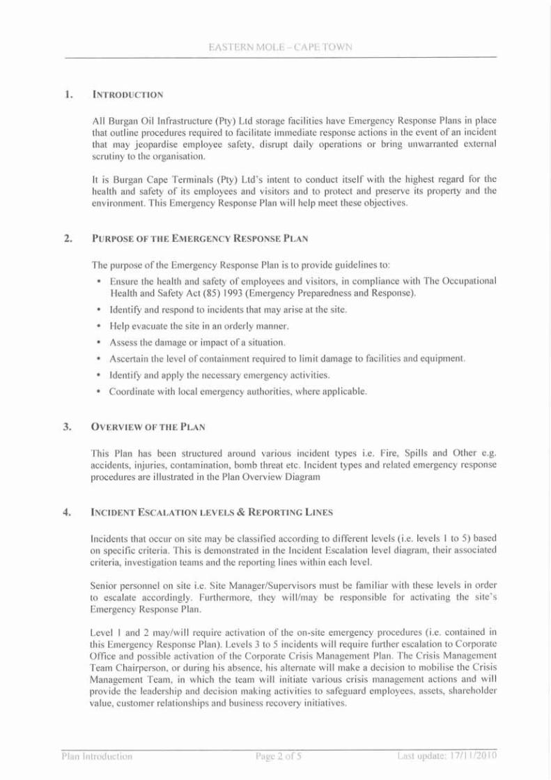

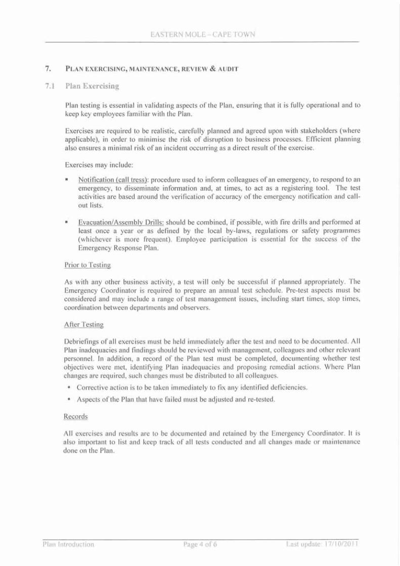


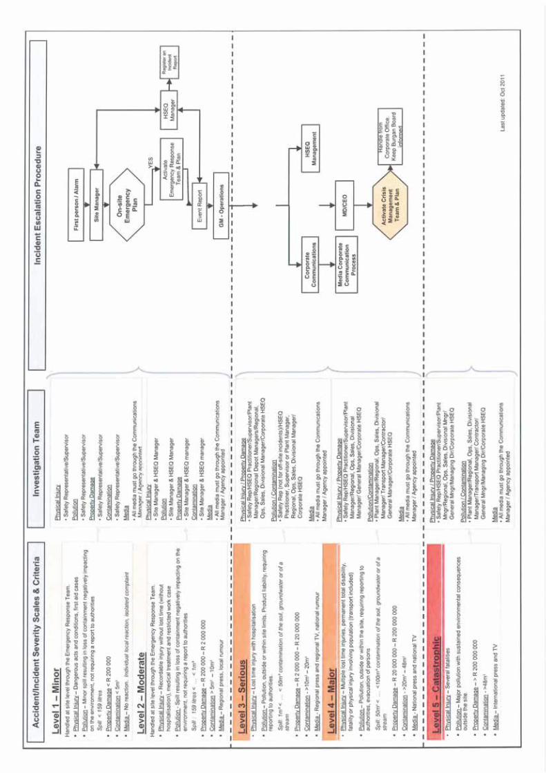

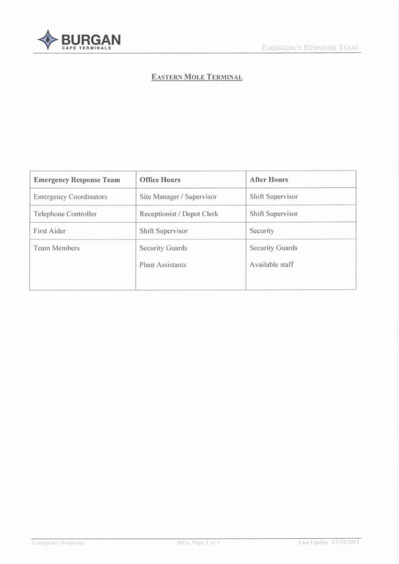


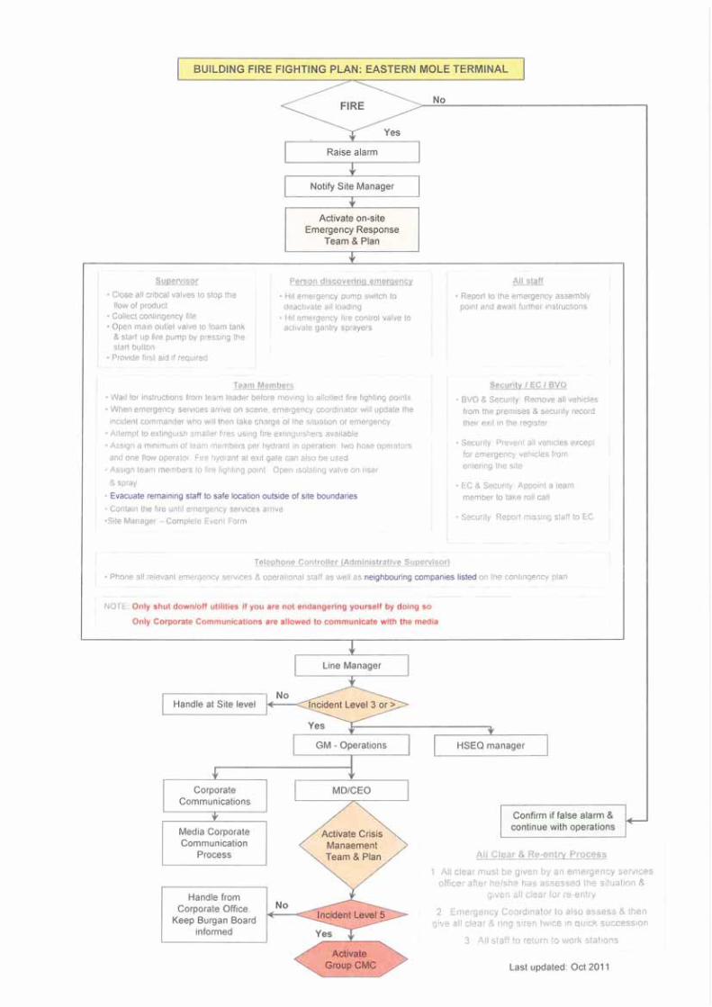
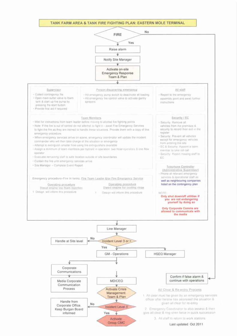


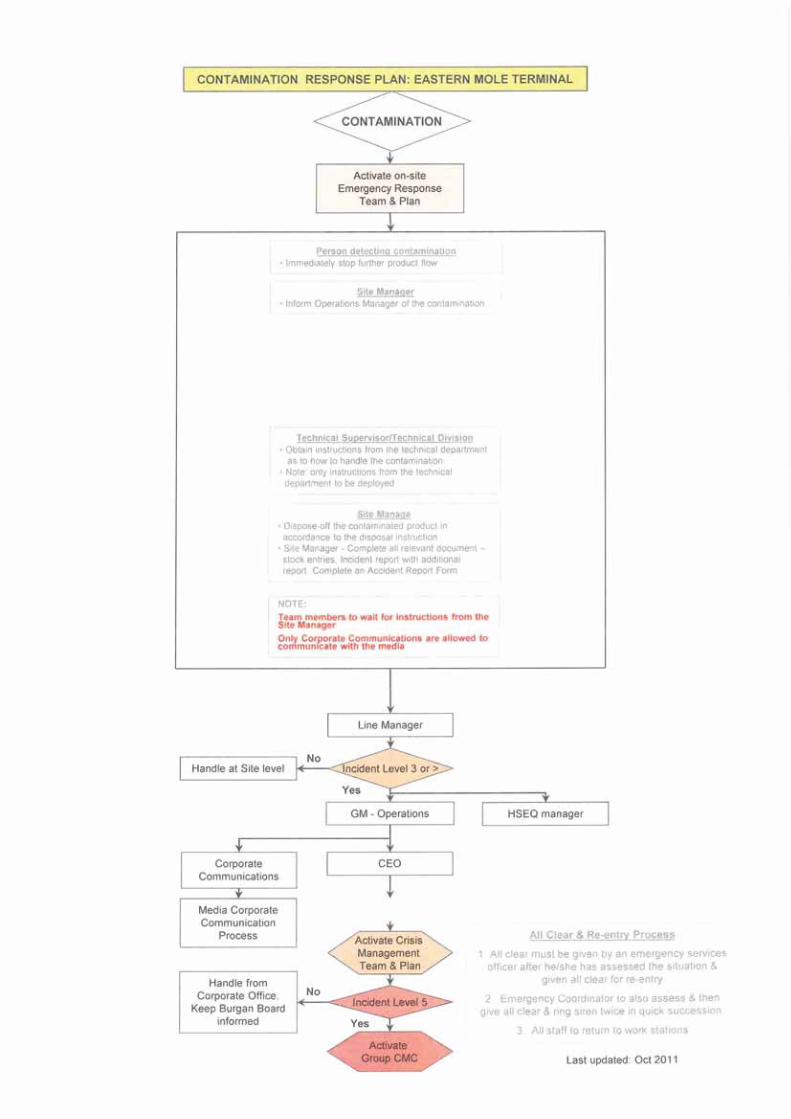
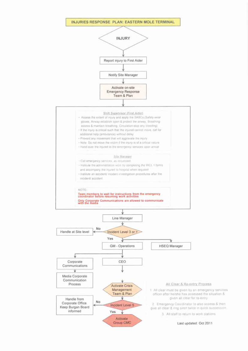

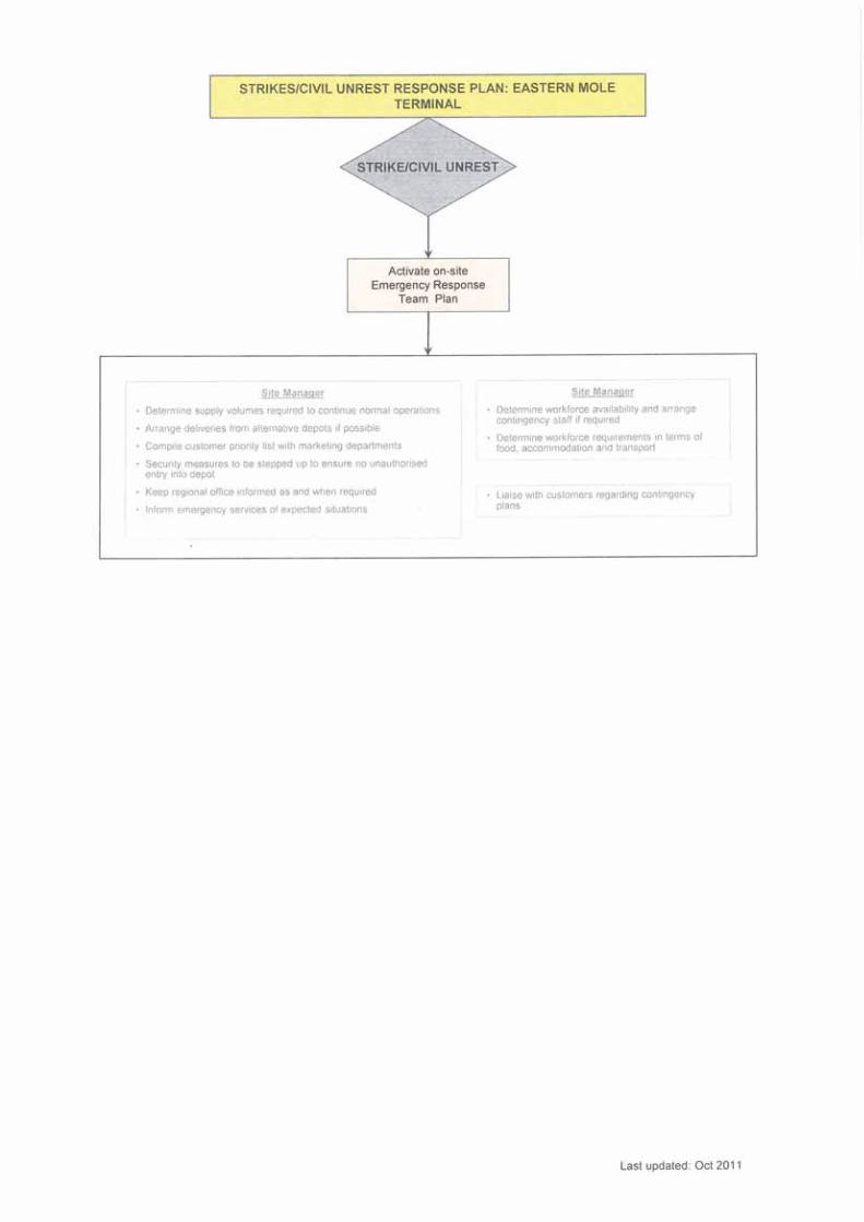
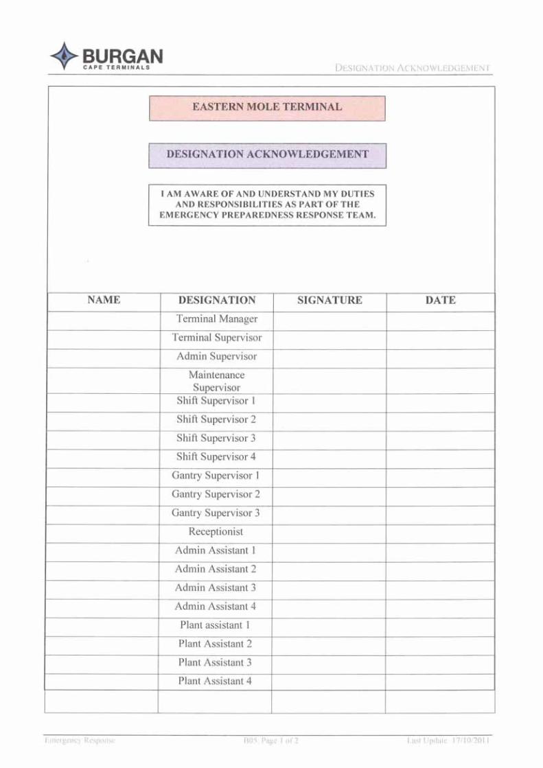


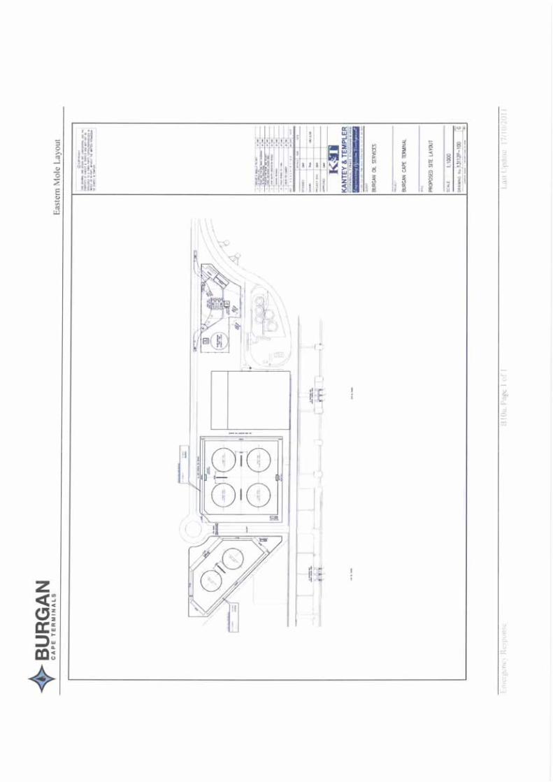


Annex F
Fault Trees for Tank Overfilling
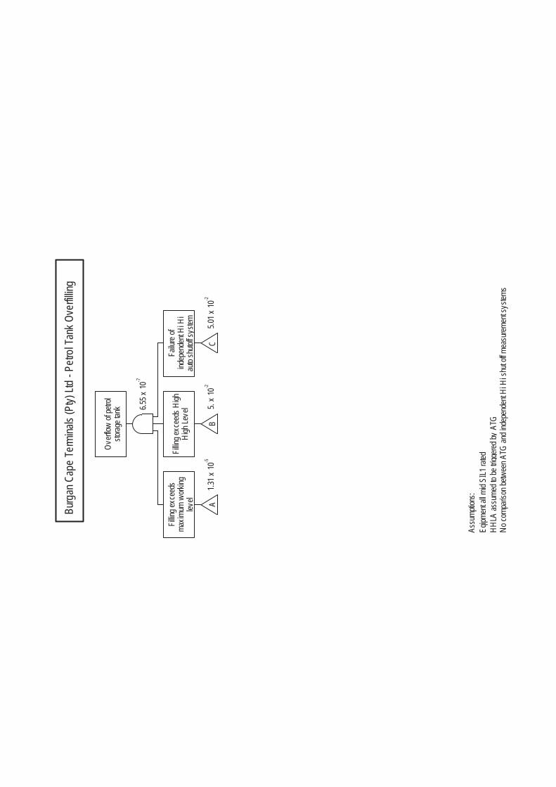
storag
e tan
kOv
erflow
of pe
trol
6.55 x
10 -7
level
maxim
um w
orking
Fillin
g exc
eeds 1.3
1 x 10
-5A
High
Leve
lFil
ling e
xcee
ds H
igh
5. x
10 -2
B
auto
shuto
ff sys
temind
epen
dent
Hi H
iFa
ilure
of
5.01 x
10 -2
C
HHLA
assu
med t
o be t
rigge
red by
ATG
No co
mpari
son b
etwee
n ATG
and i
ndep
ende
nt Hi
Hi s
hut o
ff mea
surem
ent s
ystem
s
Eqipm
ent a
ll mid
SIL1
rated
Assu
mptio
ns:
Burg
an C
ape
Term
inals
(Pty)
Ltd
- Petr
ol Ta
nk O
verfil
ling
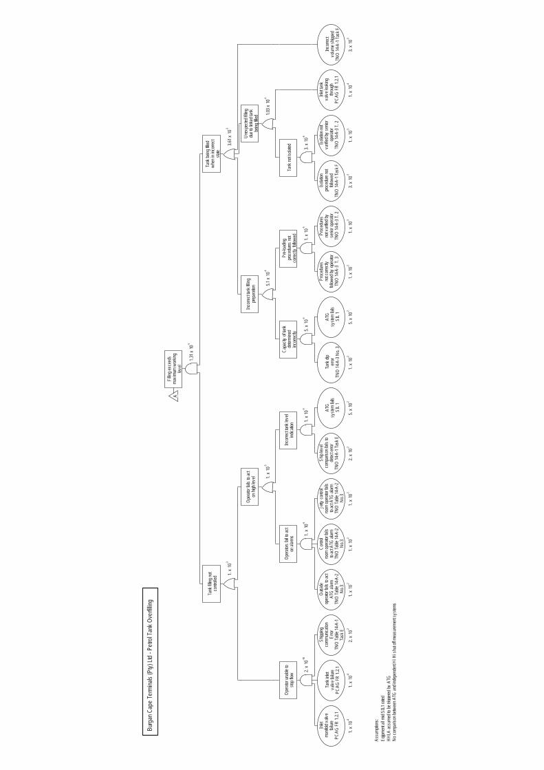
level
maxim
um w
orking
Fillin
g exc
eeds 1.3
1 x 10
-5
A
contr
olled
Tank
fillin
g not 1.
x 10
-3
stop f
lowOp
erator
unab
le to
2. x
10
-1
0
PCAG
FR
1.2.1
failur
ema
nifold
valv
eInl
et
1. x
10 -4
PCAG
FR
1.2.1
valve
failu
reTa
nk in
let
1. x
10 -4
Task
ETN
O Ta
ble 14
-A-1
Error
comm
unica
tion
Shipp
ing
2. x
10 -2
on hi
gh le
vel
Opera
tor fa
ils to
act
1. x
10 -3
on al
arms
Opera
tors f
ail to
act
1. x
10 -6
No.3
TNO
Table
14-A
-2AT
G ala
rmop
erator
fails
to ac
tOu
tside
1. x
10 -2
No.3
TNO
Table
14-A
-2to
act A
TG al
armroo
m op
erator
fails
Contr
ol
1. x
10 -2
No.3
TNO
Table
14-A
-2to
act A
TG al
armroo
m op
erator
fails
Jetty
contr
ol
1. x
10 -2
indica
tion
Incorr
ect ta
nk le
vel
1. x
10 -3
TNO
14-A
-1 Ta
sk E
detec
t erro
rco
mpari
son f
ails t
oSh
ip lev
el
2. x
10 -2
SIL 1
syste
m fai
lsAT
G
5. x
10 -2
state
when
in in
corre
ctTa
nk be
ing fil
led 3.61 x
10 -3
prepa
ration
Incorr
ect ta
nk fil
ling
5.1 x
10 -4
incorr
ectly
deter
mine
dCa
pacit
y of
tank
5. x
10 -4
TNO
14-A
-3 No
. 3err
orTa
nk di
p
1. x
10 -2
SIL 1
syste
m fai
lsAT
G
5. x
10 -2
corre
ctly
follow
edpro
cedu
res no
tPr
e-loa
ding 1.
x 10
-5
TNO
14-A
-3 T.
3fol
lowed
by op
erator
not c
orrec
tlyPr
oced
ures
1. x
10 -2
TNO
14-A
-3 T.
2se
nior o
perat
orno
t vari
fied b
yPr
oced
ures
1. x
10 -3
being
filled
due t
o link
ed ta
nkUn
expe
cted f
illing
1.03 x
10 -4
Tank
not is
olated 3.
x 10
-6
TNO
14-A
-1 Ta
sk F
follow
edpro
cedu
re no
tIso
lation
3. x
10 -3
TNO
14-A
-3 T.
2op
erator
varifi
ed by
senio
rIso
lation
not
1. x
10 -3
PCAG
FR
1.2.1
throu
ghva
lve le
aking
Inlet
tank
1. x
10 -4
TNO
14-A
-1 Ta
sk F
volum
e ship
ped
Incorr
ect
3. x
10 -3
HHLA
assu
med t
o be t
rigge
red by
ATG
No co
mpari
son b
etwee
n ATG
and i
ndep
ende
nt Hi
Hi s
hut o
ff mea
surem
ent s
ystem
s
Eqipm
ent a
ll mid
SIL1
rated
Assu
mptio
ns:
Burg
an C
ape
Term
inals
(Pty)
Ltd
- Petr
ol Ta
nk O
verfil
ling
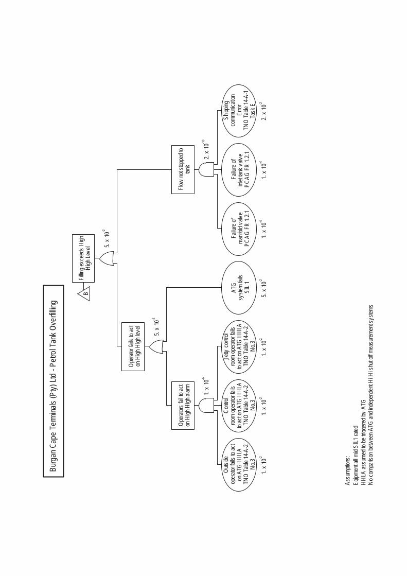
High
Leve
lFil
ling e
xcee
ds H
igh
5. x
10 -2
B
on H
igh H
igh le
vel
Opera
tor fa
ils to
act
5. x
10 -2
on H
igh H
igh al
armOp
erator
s fail
to ac
t
1. x
10 -6
No.3
TNO
Table
14-A
-2on
ATG
HHL
Aop
erator
fails
to ac
tOu
tside
1. x
10 -2
No.3
TNO
Table
14-A
-2to
act o
n ATG
HHL
Aroo
m op
erator
fails
Contr
ol
1. x
10 -2
No.3
TNO
Table
14-A
-2to
act o
n ATG
HHL
Aroo
m op
erator
fails
Jetty
contr
ol
1. x
10 -2
SIL 1
syste
m fai
lsAT
G
5. x
10 -2
tank
Flow
not s
toppe
d to
2. x
10
-1
0
PCAG
FR
1.2.1
manif
old v
alve
Failu
re of
1. x
10 -4
PCAG
FR
1.2.1
inlet
tank v
alve
Failu
re of
1. x
10 -4
Task
ETN
O Ta
ble 14
-A-1
Error
comm
unica
tion
Shipp
ing
2. x
10 -2
HHLA
assu
med t
o be t
rigge
red by
ATG
No co
mpari
son b
etwee
n ATG
and i
ndep
ende
nt Hi
Hi s
hut o
ff mea
surem
ent s
ystem
s
Eqipm
ent a
ll mid
SIL1
rated
Assu
mptio
ns:
Burg
an C
ape
Term
inals
(Pty)
Ltd
- Petr
ol Ta
nk O
verfil
ling

auto
shuto
ff sys
temind
epen
dent
Hi H
iFa
ilure
of
5.01 x
10 -2
C
Valve
is no
t clos
ed
1. x
10 -4
PCAG
FR
1.2.1
failur
e to c
lose
ASOV
1. x
10 -2
No.3
TNO
Table
14-A
-2aft
er IH
HLA
chec
ked a
nd cl
osed
Valve
s not
1. x
10 -2
SIL 1
HHL s
ystem
fails
Indep
ende
nt
5. x
10 -2
HHLA
assu
med t
o be t
rigge
red by
ATG
No co
mpari
son b
etwee
n ATG
and i
ndep
ende
nt Hi
Hi s
hut o
ff mea
surem
ent s
ystem
s
Eqipm
ent a
ll mid
SIL1
rated
Assu
mptio
ns:
Burg
an C
ape
Term
inals
(Pty)
Ltd
- Petr
ol Ta
nk O
verfil
ling

ERM consulting services worldwide www.erm.com
ERM has 150 offices in the following countries worldwide Argentina Australia Belgium Brazil Canada China Colombia France Germany Hong Kong India Indonesia Ireland Italy Japan Kazakhstan Kenya Malaysia Mexico Mozambique The Netherlands Contact: Gary McFadden Industrial Risk Partner Tel: +27 (0)11 798 4300 Mobile: +27 (0)82 374 6901 Email: [email protected]
Johannesburg Office Building 32, The Woodlands, Woodlands Drive, Woodmead, Sandton Johannesburg, South Africa T: +27 (0) 11 798 4300 Cape Town Office The Great Westerford 2nd Floor 240 Main Road Rondebosch, 7700 Cape Town, South Africa Tel: +27 (0) 21 702 9100 Durban Office Unit 6 St Helier Office Park Winston Park c/o St Helier Rd & Forbes Drive Gillits Durban, South Africa Tel: +27 (0) 31 767 2080
Maputo Office 12th Floor, Vodacom Building 649 Rua dos Desportistas Maputo, Mozambique T:+258 84 310 9500 Nairobi Office 4th Floor, Cavendish Block, 14 Riverside Complex Riverside Drive, Nairobi, Kenya T: +254 (020) 4231 234 / 201 Fax:+27 (0) 21 701 7900
New Zealand Panama Peru Poland Portugal Puerto Rico Romania Russia Singapore South Africa South Korea Spain Switzerland Sweden Taiwan Thailand United Arab Emirates United Kingdom United States of America Vietnam