c2406, c2606 installation instructions 2007-2013...
TRANSCRIPT

»Zone Offroad Products • 491 W. Garfield Ave., Coldwater, MI 49036 • 888.998.ZONE • www.zoneoffroad.com
Read and understand all instructions and warnings prior to installation of product and operation of vehicle.Zone Offroad Products recommends this system be installed by a professional technician. In addition to these instructions, profes-sional knowledge of disassembly/ reassembly procedures and post installation checks must be known. Minimum tool requirements include the following: Assorted metric and standard wrenches, hammer, hydraulic floor jack and a set of jack stands. See the "Special Tools Required" section for additional tools needed to complete this installation properly and safely.
»Product Safety Warning
Certain Zone Suspension Products are intended to improve off-road performance. Modifying your vehicle for off-road use may result in the vehicle handling differently than a factory equipped vehicle. Extreme care must be used to prevent loss of control or vehicle rollover. Failure to drive your modified vehicle safely may result in serious injury or death. Zone Offroad Products does not recommend the combined use of suspension lifts, body lifts, or other lifting devices.
You should never operate your modified vehicle under the influence of alcohol or drugs. Always drive your modified vehicle at reduced speeds to ensure your ability to control your vehicle under all driving conditions. Always wear your seat belt.
»technical SuPPort
Live Chat provides instant communication with Zone tech support. Anyone can access live chat through a link on www.zoneoffroad.com .
www.zoneoffroad.com may have additional information about this product including the latest instructions, videos, photos, etc.
Send an e-mail to [email protected] detailing your issue for a quick response.
888.998.ZONE Call to speak directly with Zone tech support.
»Pre-inStallation noteS
1. Special literature required: OE Service Manual for model/year of vehicle. Refer to manual for proper disassembly/reassembly procedures of OE and related components.
2. Adhere to recommendations when replacement fasteners, retainers and keepers are called out in the OE manual.
3. Larger rim and tire combinations may increase leverage on suspension, steering, and related components. When selecting combinations larger than OE, consider the addi-tional stress you could be inducing on the OE and related components.
4. Post suspension system vehicles may experience drive line vibrations. Angles may require tuning, slider on shaft may require re-placement, shafts may need to be lengthened or trued, and U-joints may need to be replaced.
5. Secure and properly block vehicle prior to installation of Zone Offroad Products. Always wear safety glasses when using power tools.
6. If installation is to be performed without a hoist, Zone Offroad Products recommends rear alterations first.
7. Due to payload options and initial ride height variances, the amount of lift is a base figure. Final ride height dimensions may vary in accordance to original vehicle attitude. Always measure the attitude prior to beginning installation.
rev122916
C2406, C2606 Installation Instructions2007-2013 Chevy 1/2 Ton 4wd Pickup4.5", 6.5" Suspension System
Difficulty Leveleasy 1 2 3 4 5 difficult
Estimated installation: 7-9 hours
Special Tools RequiredWelder
Quality Strut Compressor
Reciprocating Saw or Equivalent
36mm Axle Socket
Tire/Wheel Fitment6.5"Lift:
35 x 12.50 on 17x9, 18x9 w/ 5" BS
35 x 12.50 on 20x9 w/ 5.75" BS
33 x 12.50 on 17x8 w/ 4.5" BS
4.5"Lift:
33 x 12.50 on 17x9, 18x9 w/ 5" BS
33 x 12.50 on 20x9 w/ 5.75" BS
32 x 11.50 on 17x8 w/ 4.5" BS
pg. 2 - C2406, C2606
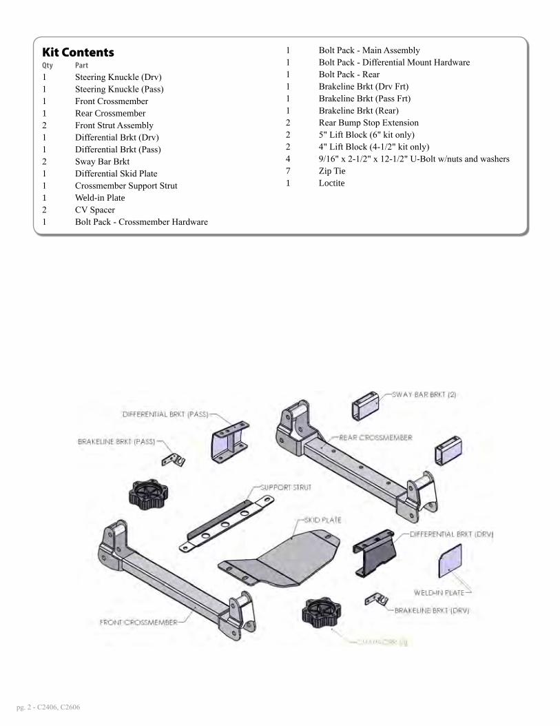
Kit ContentsQty Part
1 Steering Knuckle (Drv)1 Steering Knuckle (Pass)1 Front Crossmember1 Rear Crossmember2 Front Strut Assembly1 Differential Brkt (Drv)1 Differential Brkt (Pass)2 Sway Bar Brkt1 Differential Skid Plate1 Crossmember Support Strut1 Weld-in Plate2 CV Spacer1 Bolt Pack - Crossmember Hardware
1 Bolt Pack - Main Assembly1 Bolt Pack - Differential Mount Hardware1 Bolt Pack - Rear1 Brakeline Brkt (Drv Frt)1 Brakeline Brkt (Pass Frt)1 Brakeline Brkt (Rear)2 Rear Bump Stop Extension2 5" Lift Block (6" kit only)2 4" Lift Block (4-1/2" kit only)4 9/16" x 2-1/2" x 12-1/2" U-Bolt w/nuts and washers7 Zip Tie1 Loctite

C2406, C2606 Installation - pg. 3
INSTALLATION INSTRUCTIONS
»Pre-inStallation noteS1. The installation of this kit requires the use of a good quality coil spring compres-
sor to replace the front coil-over strut. If you do not have a compressor, the strut assemblies can be removed and taken to most any local muffler/service shop and have the struts swapped. The coil springs are under extreme pressure and need to be handled as such.
2. The installation of this kit requires minor welding of a reinforcement plate. We recommend this procedure be performed by an experienced welder. If neces-sary, this kit can be completely installed and then driven to a shop/welder to have the plate installed/welded. This method will make reaching the weld loca-tions slightly more difficult but it can be done if need be.
»front inStallation1. Park the vehicle on a clean, flat surface and block the rear wheels for safety.
2. Disconnect the positive and negative battery cables from the battery.
3. Raise the front of the vehicle with a hydraulic jack and support the frame with jack stands just behind the rear lower control arm pocket.
4. Remove the wheels.
5. Disconnect the ABS line from the connector on the frame Figure 1. Remove the ABS line from the retaining clips at the frame, upper control arm and knuckle.
6. Disconnect the brake line bracket from the upper control arm Figure 1. Save bolt.
Figure 1
7. Disconnect the steering from the knuckle Figure 2. Remove the tie rod end nut. Strike the knuckle near the tie rod end with a hammer to dislodge it. Save the mounting nut.
Important—measure before starting!Measure from the center of the wheel up to the bottom edge of the wheel opening
LF__________ RF__________
LR__________ RR__________
Step 7 NoteDo not strike the tie rod end with the hammer, only the knuckle.

pg. 4 - C2406, C2606
Figure 2
8. Remove the two brake caliper mount bolts and remove the caliper assembly from the knuckle Figure 3. Hang the caliper securely out of the way. DO NOT hang the caliper by the brake hose. Save caliper bolts.
Figure 3
9. Remove the hub dust cap Figure 4. Remove the axle shaft nut. Retain nut and cap.
Figure 4
Step 9 NoteUse a small chisel and hammer to carefully separate the edge of the cap from the hub. Work around the circumference of the cap. The axle nut will require a 36mm socket.

C2406, C2606 Installation - pg. 5
10. Remove the sway bar links from the sway bar and the lower control arm Figure 5. Save the links, bushings and hardware.
Figure 5
11. Remove the sway bar from the frame by removing the four bushing cap mount-ing bolts Figure 6. Save all sway bar components.
Figure 6
12. Mark each of the front strut bodies to indicate driver’s verses passenger’s side. Make the marks on the side of the strut that is facing out.
13. Support the lower control arm with a jack. Remove the lower strut mount bolts Figure 7. Save bolts.
pg. 6 - C2406, C2606
Figure 7
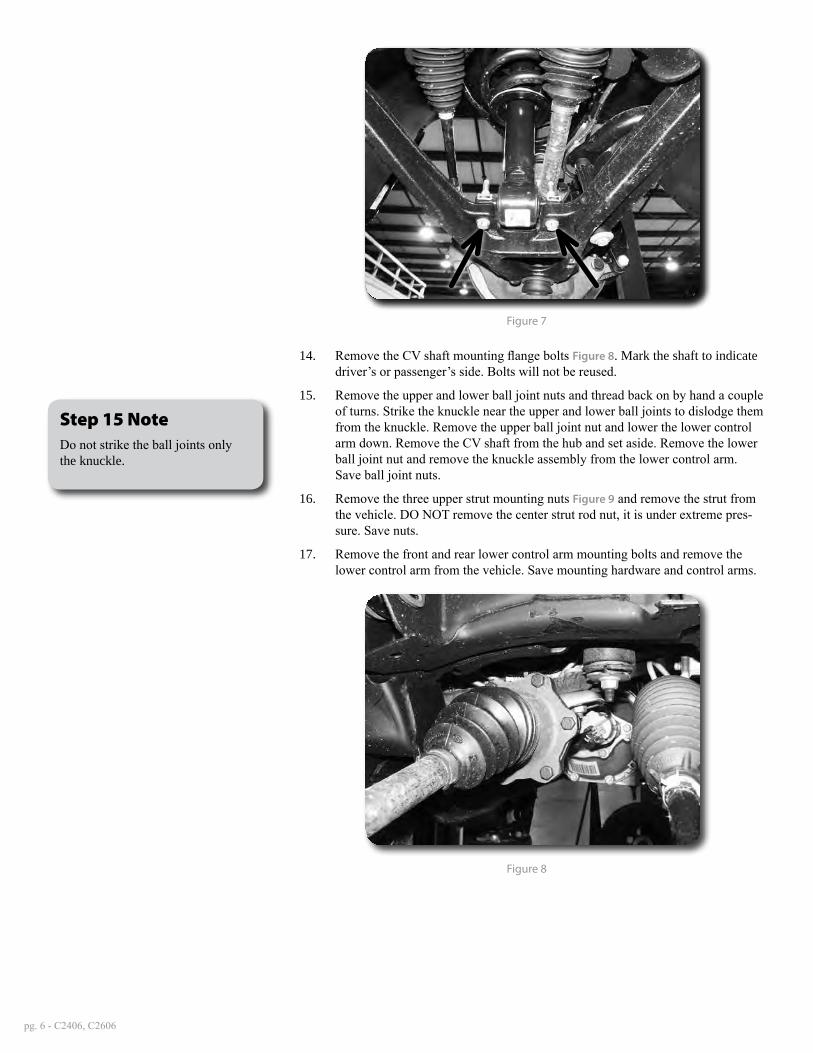
14. Remove the CV shaft mounting flange bolts Figure 8. Mark the shaft to indicate driver’s or passenger’s side. Bolts will not be reused.
15. Remove the upper and lower ball joint nuts and thread back on by hand a couple of turns. Strike the knuckle near the upper and lower ball joints to dislodge them from the knuckle. Remove the upper ball joint nut and lower the lower control arm down. Remove the CV shaft from the hub and set aside. Remove the lower ball joint nut and remove the knuckle assembly from the lower control arm. Save ball joint nuts.
16. Remove the three upper strut mounting nuts Figure 9 and remove the strut from the vehicle. DO NOT remove the center strut rod nut, it is under extreme pres-sure. Save nuts.
17. Remove the front and rear lower control arm mounting bolts and remove the lower control arm from the vehicle. Save mounting hardware and control arms.
Figure 8
Step 15 NoteDo not strike the ball joints only the knuckle.
C2406, C2606 Installation - pg. 7
Figure 9
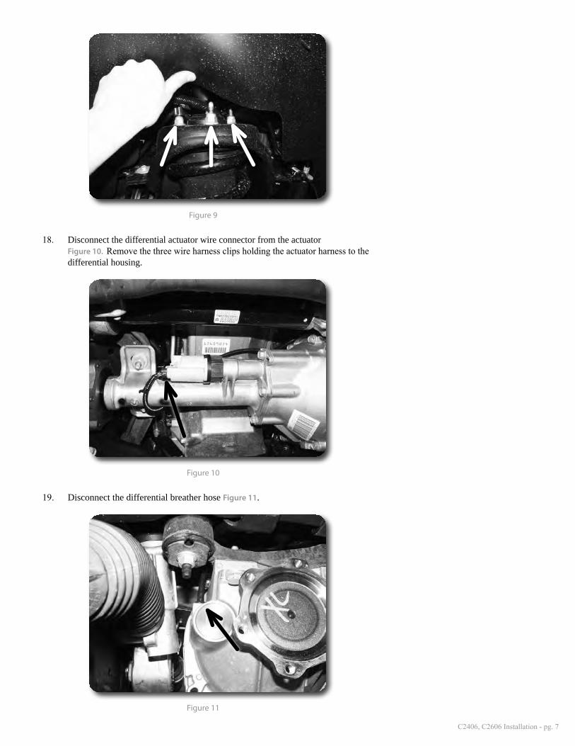
18. Disconnect the differential actuator wire connector from the actuator Figure 10. Remove the three wire harness clips holding the actuator harness to the differential housing.
Figure 10
19. Disconnect the differential breather hose Figure 11.
Figure 11

pg. 8 - C2406, C2606
20. Make an alignment mark to show the relationship between the front driveshaft and the differential input flange. Remove the four driveshaft bolts and discon-nect the driveshaft from the differential. Save bolts.
21. Remove the four bolts and the factory rear crossmember from the vehicle Figure 12. Crossmember and hardware will not be reused.
Figure 12
22. Support the front differential with an appropriate jack. Remove the two driver’s side differential mounting bolts Figure 13 and the two passenger’s side mounting nuts Figure 10. Carefully lower the differential to the ground. Save mounting hardware.
23. The driver’s side rear lower control arm pocket must be cut to provide clearance for the front differential in the relocated position. The entire area needs to be cleaned of any oil, grease and/or undercoating. These coatings are flammable.
24. Measure from the inside of the driver's side control arm pocket out 3-1/2" and mark. Repeat this measurement on the opposite side of the pocket. Make vertical cut lines at the 3-1/2” mark up both front and back faces of the pocket Figure 14.
Figure 13
Step 22 NoteWe highly recommend having an assistant to help with removal of the front differential.
Step 23 NoteA putty knife and parts cleaning solvent work well to remove under-coating.

C2406, C2606 Installation - pg. 9
3-1/2"
Figure 14
25. Make a vertical cut along each of the cut lines on the front and back faces of the control arm pocket with a reciprocating saw (recommended), cut-off wheel or plasma cutter. Be careful, the undercoating on the frame is flammable and can melt and drip off the frame. Keep an appropriate fire extinguisher near by.
26. With the vertical cuts complete, cut the top portion of the pocket by connecting the two cuts Figure 15.
Figure 15
27. Place the provided weld-in plate up against the cut edge of the control arm pocket. The plate should be flush with the bottom edge of the pocket and overhang the front and back outside surfaces an equal amount. The chamfered corner of the plate should be in the top-front position Figure 16. Tack weld the plate in place.
Step 25 NoteMeasure twice, cut once!!!
Step 27 NoteWelding should be performed by an experienced welder. See pre-installation notes at the beginning of these instructions.
pg. 10 - C2406, C2606
Figure 16
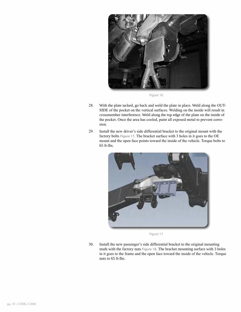
28. With the plate tacked, go back and weld the plate in place. Weld along the OUT-SIDE of the pocket on the vertical surfaces. Welding on the inside will result in crossmember interference. Weld along the top edge of the plate on the inside of the pocket. Once the area has cooled, paint all exposed metal to prevent corro-sion.
29. Install the new driver’s side differential bracket to the original mount with the factory bolts Figure 17. The bracket surface with 3 holes in it goes to the OE mount and the open face points toward the inside of the vehicle. Torque bolts to 65 ft-lbs.
Figure 17
30. Install the new passenger’s side differential bracket to the original mounting studs with the factory nuts Figure 18. The bracket mounting surface with 3 holes in it goes to the frame and the open face toward the inside of the vehicle. Torque nuts to 65 ft-lbs.

C2406, C2606 Installation - pg. 11
Figure 18
31. The small corner of the differential housing that will rest closest to the new weld -in plate needs to be slightly trimmed Figure 19 to provided adequate clearance when installed. Only about 3/8" of material needs to be removed along the length of the corner. The trimming can be done with a reciprocating saw, hack saw or grinder. Measure from the top corner and mark 3/8" in both directions. Extended the cut lines down along the housing.
Figure 19
32. Using an appropriate jack, install the differential in the vehicle by attaching it to the new driver’s and passenger’s differential brackets. Fasten the differential to the brackets with ½” x 1-3/4” bolts, nuts and washers. Use two ½” SAE washers on each bolt for the driver’s side. Use one ½” SAE washer and one extra large ½” washer on the passenger’s side. The extra large washer will go against the differen-tial housing flange with the large slots Figures 20. Torque the ½” hardware to 65 ft-lbs. Pull the differential forward as the passenger’s side bolts are tightened.
Step 32 NoteHardware for the differential drop brackets is located in hardware pack #644.

pg. 12 - C2406, C2606
Figure 20
33. Reconnect the differential actuator wiring. Reattach the wire to the differential housing with the provided wire ties.
34. Reconnect the differential breather line. The line will need to be removed from retaining clips above to gain slack.
35. Reconnect the front drive shaft to the differential with the original hardware. Torque bolts to 19 ft-lbs.
36. Install the new rear crossmember with the factory lower control arm bolts, nuts and washers. When installed the rectangular cross tube should offset closer to the rear of the vehicle Figure 21. Run the bolts from front to rear. Leave hard-ware loose.
37. Install the front crossmember in the control arm pockets with the factory lower control arm bolts, nuts and washers. When installed the offset in the crossmem-ber ends should be toward the front of the vehicle Figure 21. Run bolts from front to rear. Leave hardware loose.
Figure 21
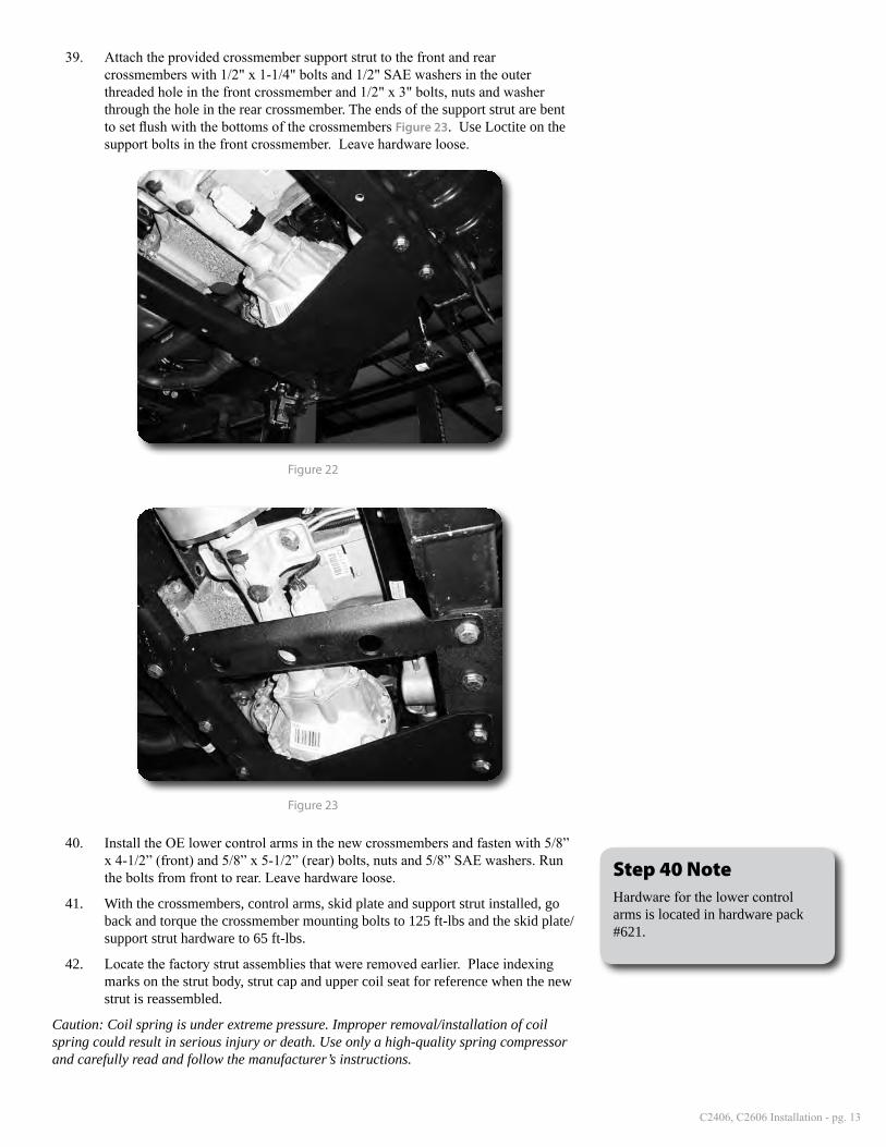
38. Attach the provided differential skid plate to the front and rear crossmembers with two 1/2" x 1-1/4" bolts and 1/2" SAE washers in the outer threaded holes in the front crossmember and one 1/2" x 3" bolt, nut and washers through the hole in the rear crossmember. Figure 22. Use Loctite on all skid plate bolts in the front crossmember. Leave hardware loose.
Step 34 NoteThe breather line may need to be accessed through the engine com-partment to be rerouted for more slack.
Step 38, 39 NoteHardware for the differential skid plate and crossmember support strut is located in hardware pack #643.
C2406, C2606 Installation - pg. 13
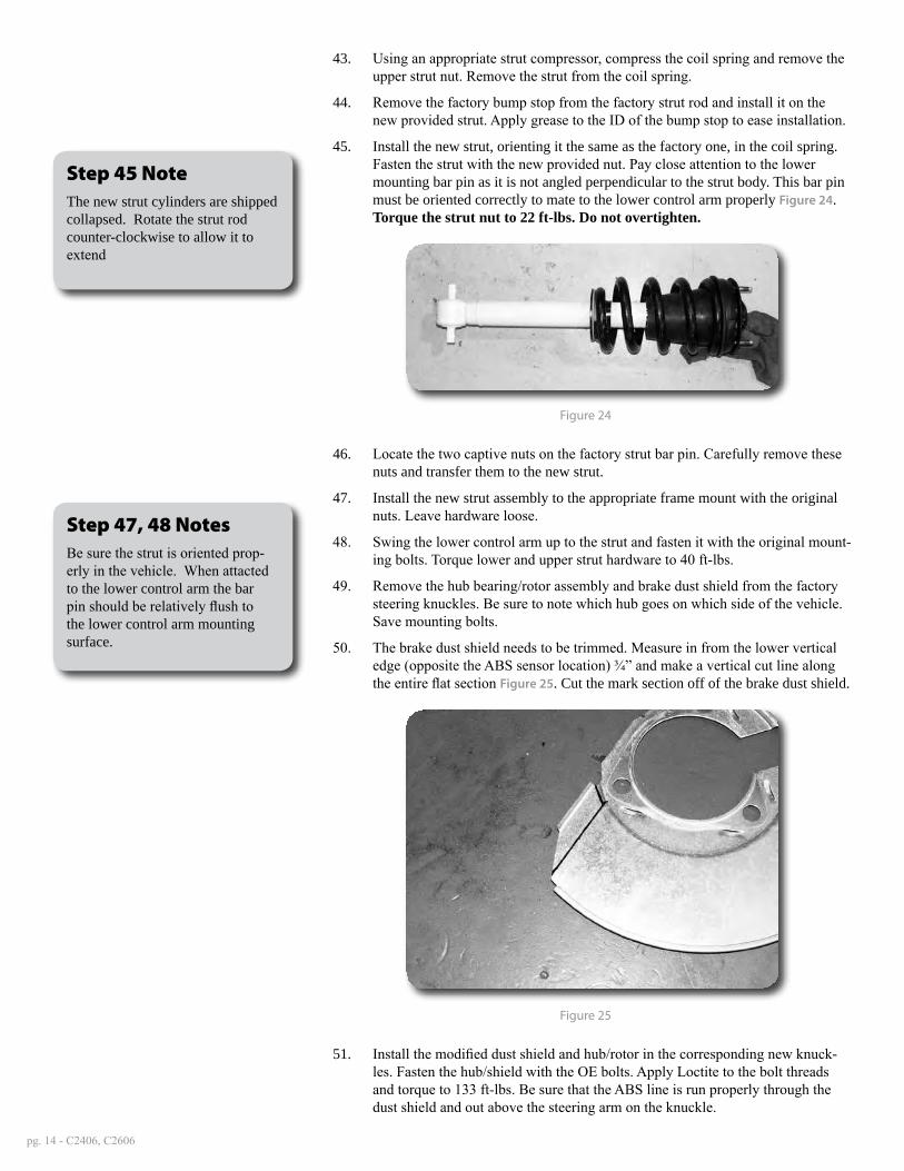
39. Attach the provided crossmember support strut to the front and rear crossmembers with 1/2" x 1-1/4" bolts and 1/2" SAE washers in the outer threaded hole in the front crossmember and 1/2" x 3" bolts, nuts and washer through the hole in the rear crossmember. The ends of the support strut are bent to set flush with the bottoms of the crossmembers Figure 23. Use Loctite on the support bolts in the front crossmember. Leave hardware loose.
Figure 22
Figure 23
40. Install the OE lower control arms in the new crossmembers and fasten with 5/8” x 4-1/2” (front) and 5/8” x 5-1/2” (rear) bolts, nuts and 5/8” SAE washers. Run the bolts from front to rear. Leave hardware loose.
41. With the crossmembers, control arms, skid plate and support strut installed, go back and torque the crossmember mounting bolts to 125 ft-lbs and the skid plate/support strut hardware to 65 ft-lbs.
42. Locate the factory strut assemblies that were removed earlier. Place indexing marks on the strut body, strut cap and upper coil seat for reference when the new strut is reassembled.
Caution: Coil spring is under extreme pressure. Improper removal/installation of coil spring could result in serious injury or death. Use only a high-quality spring compressor and carefully read and follow the manufacturer’s instructions.
Step 40 NoteHardware for the lower control arms is located in hardware pack #621.
pg. 14 - C2406, C2606
43. Using an appropriate strut compressor, compress the coil spring and remove the upper strut nut. Remove the strut from the coil spring.
44. Remove the factory bump stop from the factory strut rod and install it on the new provided strut. Apply grease to the ID of the bump stop to ease installation.
45. Install the new strut, orienting it the same as the factory one, in the coil spring. Fasten the strut with the new provided nut. Pay close attention to the lower mounting bar pin as it is not angled perpendicular to the strut body. This bar pin must be oriented correctly to mate to the lower control arm properly Figure 24. Torque the strut nut to 22 ft-lbs. Do not overtighten.
Figure 24
46. Locate the two captive nuts on the factory strut bar pin. Carefully remove these nuts and transfer them to the new strut.
47. Install the new strut assembly to the appropriate frame mount with the original nuts. Leave hardware loose.
48. Swing the lower control arm up to the strut and fasten it with the original mount-ing bolts. Torque lower and upper strut hardware to 40 ft-lbs.
49. Remove the hub bearing/rotor assembly and brake dust shield from the factory steering knuckles. Be sure to note which hub goes on which side of the vehicle. Save mounting bolts.
50. The brake dust shield needs to be trimmed. Measure in from the lower vertical edge (opposite the ABS sensor location) ¾” and make a vertical cut line along the entire flat section Figure 25. Cut the mark section off of the brake dust shield.
Figure 25
51. Install the modified dust shield and hub/rotor in the corresponding new knuck-les. Fasten the hub/shield with the OE bolts. Apply Loctite to the bolt threads and torque to 133 ft-lbs. Be sure that the ABS line is run properly through the dust shield and out above the steering arm on the knuckle.
Step 45 NoteThe new strut cylinders are shipped collapsed. Rotate the strut rod counter-clockwise to allow it to extend
Step 47, 48 NotesBe sure the strut is oriented prop-erly in the vehicle. When attacted to the lower control arm the bar pin should be relatively flush to the lower control arm mounting surface.

C2406, C2606 Installation - pg. 15
52. Install the assembled knuckle on the lower control arm with the original lower ball joint nut. Attach the knuckle to the upper control arm with the original upper ball joint nut. Torque the upper ball joint nut to 37 ft-lbs and the lower ball joint nut to 74 ft-lbs Figure 26.
Figure 26
53. Install the factory CV axle shaft into the hub and fasten with the original nut/washer and torque to 155 ft-lbs. Install dust cap.
54. Position the provided CV spacer between the CV shaft and the differential mounting flange Figure 27. Fasten the CV and spacer to the differential flange with 10mm x 70mm bolts and 10mm washers. Use Loctite on the bolt threads and torque to 45 ft-lbs using a crossing pattern.
Figure 27
55. Working on one side at a time, remove the tie rod end from the steering link Figure 28A. Trim 1/2" off of both the tie rod end and the steering link Figure 28B,C. This will allow for proper alignment adjustment once the kit is complete. Once the two pieces are trimmed, clean the ends of the threads and reinstall the tie rod end on the steering link. Repeat on other side of the vehicle.
Step 52 NoteTo make connecting the upper ball joint easier, loosen the upper con-trol arm cam bolts at the frame and rotate the cams to shift the control arm outward.
Step 54 NoteHardware for the CV spacers is located in hardware pack #644.

pg. 16 - C2406, C2606
Figure 28A
Figure 28B
Figure 28C
56. Disconnect the factory rubber brake line from the hard line at the frame. Re-move the retaining clip and remove the brake line from the bracket. Disconnect the bracket from the frame. Save hardware.
57. Attach the caliper to the new steering knuckle with the original mounting hard-ware. Torque bolts to 125 ft-lbs.

C2406, C2606 Installation - pg. 17
58. Carefully remove the metal retainer bracket from the factory rubber brake line. This can be done with two vice grips, pliers, or crescent wrenches.
59. Attach the provided brake line bracket to the upper control arm mount using the original mounting bolt so the bracket tab fits in the frame hole. Figure 29 Leave hardware loose.
Figure 29
60. Carefully reform the brake hard line down near the new bracket. Run the end of the rubber brake hose through the bracket and attach it to the hard line. Tighten the fitting securely. Retain the brake line to the bracket with the original clip.
61. With the brake line installed go back and torque the new brake line bracket to 20 ft-lbs.
62. Attach the ABS line to the upper control arm with the original brake line mount-ing bolt and provided wire clamp Figure 30.
Figure 30
63. Reconnect ABS line at the frame. Attach the ABS line to the steering knuckle with the provided wire clamps and ¼” x ¾” self tapping bolt and flat washer.
Step 58 NoteIt may be easier to remove the brake line from the bracket by removing it from the vehicle completely and holding the bracket in a bench vise. If the brake line is removed, the system will need to be bled.
Step 59 NoteHardware for the brake line brack-ets is located in hardware pack #643.
Step 63 NoteHardware for the brake line clamps is located in hardware pack #643.
pg. 18 - C2406, C2606
Torque bolt to 15 ft-lbs. Use zip ties to retain the remaining section of the ABS line as needed to keep it away from rotating objects Figure 31.
Figure 31
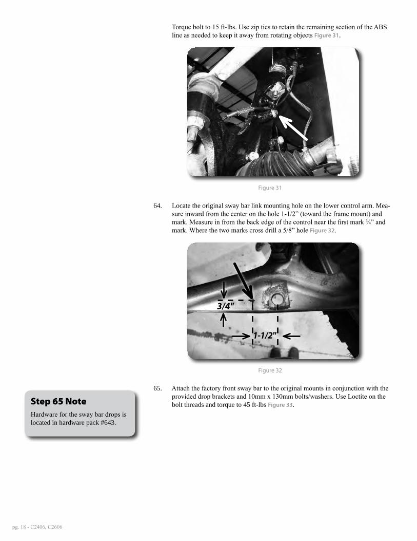
64. Locate the original sway bar link mounting hole on the lower control arm. Mea-sure inward from the center on the hole 1-1/2” (toward the frame mount) and mark. Measure in from the back edge of the control near the first mark ¾” and mark. Where the two marks cross drill a 5/8” hole Figure 32.
3/4"
1-1/2"
Figure 32
65. Attach the factory front sway bar to the original mounts in conjunction with the provided drop brackets and 10mm x 130mm bolts/washers. Use Loctite on the bolt threads and torque to 45 ft-lbs Figure 33.Step 65 Note
Hardware for the sway bar drops is located in hardware pack #643.
C2406, C2606 Installation - pg. 19
Figure 33
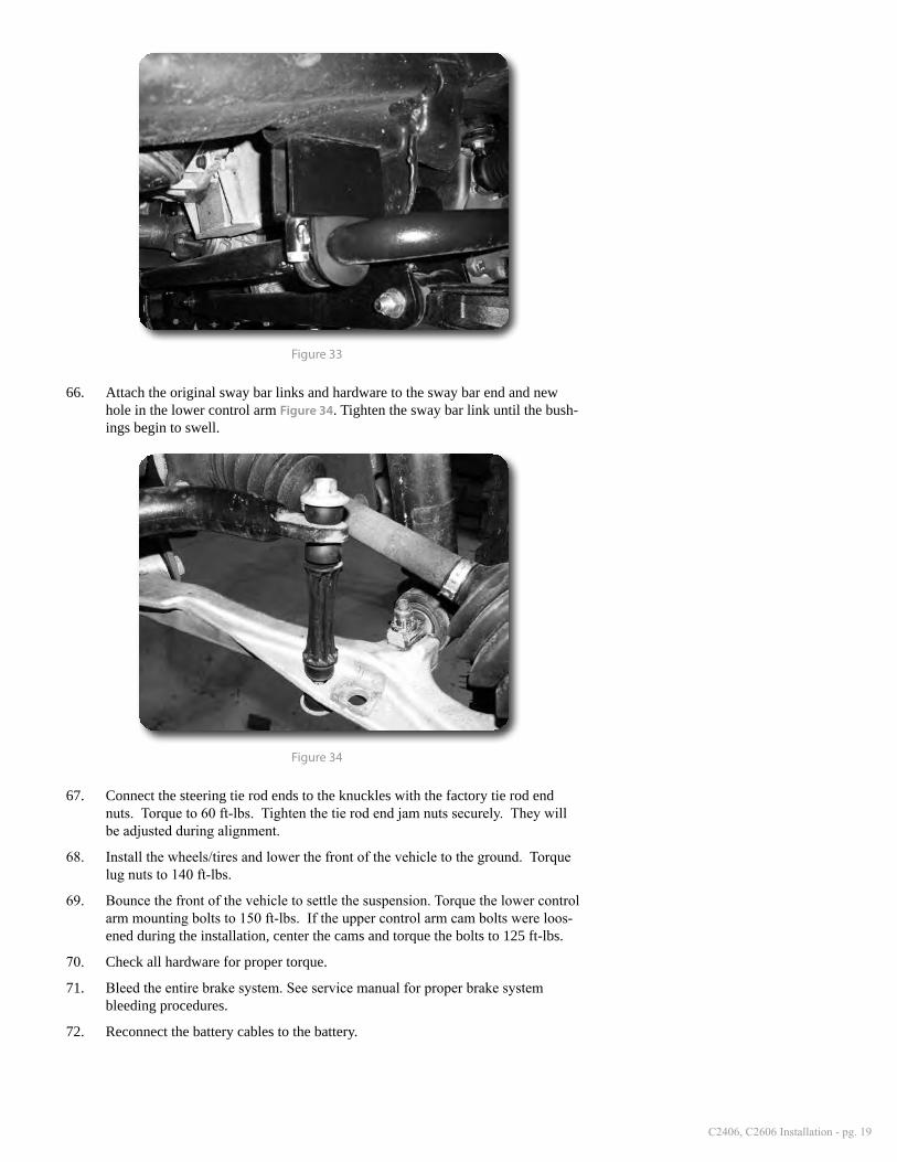
66. Attach the original sway bar links and hardware to the sway bar end and new hole in the lower control arm Figure 34. Tighten the sway bar link until the bush-ings begin to swell.
Figure 34
67. Connect the steering tie rod ends to the knuckles with the factory tie rod end nuts. Torque to 60 ft-lbs. Tighten the tie rod end jam nuts securely. They will be adjusted during alignment.
68. Install the wheels/tires and lower the front of the vehicle to the ground. Torque lug nuts to 140 ft-lbs.
69. Bounce the front of the vehicle to settle the suspension. Torque the lower control arm mounting bolts to 150 ft-lbs. If the upper control arm cam bolts were loos-ened during the installation, center the cams and torque the bolts to 125 ft-lbs.
70. Check all hardware for proper torque.
71. Bleed the entire brake system. See service manual for proper brake system bleeding procedures.
72. Reconnect the battery cables to the battery.
pg. 20 - C2406, C2606
»rear inStallation1. Block the front wheels. Safely raise the rear of the vehicle and support with jack
stands just ahead of the front leaf spring frame mount.
2. Remove the wheels.
3. Support the rear axle with a floor jack.
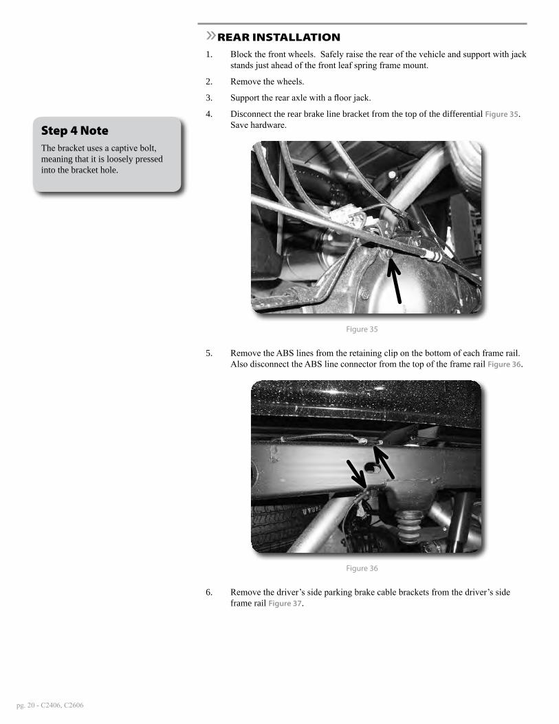
4. Disconnect the rear brake line bracket from the top of the differential Figure 35. Save hardware.
Figure 35
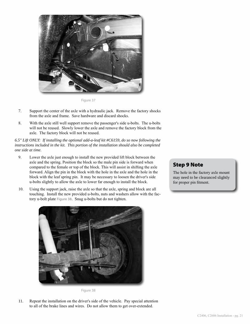
5. Remove the ABS lines from the retaining clip on the bottom of each frame rail. Also disconnect the ABS line connector from the top of the frame rail Figure 36.
Figure 36
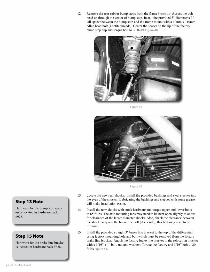
6. Remove the driver’s side parking brake cable brackets from the driver’s side frame rail Figure 37.
Step 4 NoteThe bracket uses a captive bolt, meaning that it is loosely pressed into the bracket hole.
C2406, C2606 Installation - pg. 21
Figure 37
7. Support the center of the axle with a hydraulic jack. Remove the factory shocks from the axle and frame. Save hardware and discard shocks.
8. With the axle still well support remove the passenger's side u-bolts. The u-bolts will not be reused. Slowly lower the axle and remove the factory block from the axle. The factory block will not be reused.
6.5" Lift ONLY: If installing the optional add-a-leaf kit #C6159, do so now following the instructions included in the kit. This portion of the installation should also be completed one side at time.
9. Lower the axle just enough to install the new provided lift block between the axle and the spring. Position the block so the male pin side is forward when compared to the female or top of the block. This will assist in shifting the axle forward. Align the pin in the block with the hole in the axle and the hole in the block with the leaf spring pin. It may be necessary to loosen the driver's side u-bolts slightly to allow the axle to lower far enough to install the block.
10. Using the support jack, raise the axle so that the axle, spring and block are all touching. Install the new provided u-bolts, nuts and washers allow with the fac-tory u-bolt plate Figure 38. Snug u-bolts but do not tighten.
Figure 38
11. Repeat the installation on the driver's side of the vehicle. Pay special attention to all of the brake lines and wires. Do not allow them to get over-extended.
Step 9 NoteThe hole in the factory axle mount may need to be clearanced slightly for proper pin fitment.
pg. 22 - C2406, C2606
12. Remove the rear rubber bump stops from the frame Figure 39. Access the bolt head up through the center of bump stop. Install the provided 3" diameter x 3" tall spacer between the bump stop and the frame mount with a 10mm x 110mm Allen head bolt (Loctite threads). Center the spacer on the lip of the factory bump stop cup and torque bolt to 35 ft-lbs Figure 40.
Figure 39
Figure 40
13. Locate the new rear shocks. Install the provided bushings and steel sleeves into the eyes of the shocks. Lubricating the bushings and sleeves with some grease will make installation easier.
14. Install the new shocks with stock hardware and torque upper and lower bolts to 65 ft-lbs. The axle mounting tabs may need to be bent open slightly to allow for clearance of the larger diameter shocks. Also, check the clearance between the shock body and the brake line bolt (drv’s side), this bolt may need to be trimmed.
15. Install the provided straight 3" brake line bracket to the top of the differential using factory mounting hole and bolt which must be removed from the factory brake line bracket. Attach the factory brake line bracket to the relocation bracket with a 5/16” x 1” bolt, nut and washers. Torque the factory and 5/16” bolt to 20 ft-lbs Figure 41.
Step 13 NoteHardware for the bump stop spac-ers is located in hardware pack #628.
Step 15 NoteHardware for the brake line bracket is located in hardware pack #628.

C2406, C2606 Installation - pg. 23
Figure 41
16. Reconnect the ABS lines to the plastic retaining clip at the bottom of each frame rail. The connector will not be reattached to the top of the frame. Reroute the lines as necessary to gain proper slack.
17. Reconnect the parking brake cable brackets to the driver's side frame rail with the original hardware. The driver's side cable will have to be removed from the rear braket to gain appropriate slack. Torque bolts to 20 ft-lbs.
18. Install wheels and tires. Torque lug nuts to 140 ft-lbs. Lower vehicle.
19. Bounce the rear of the vehicle to settle the suspension. Torque leaf spring u-bolts to 100-120 ft-lbs.
»PoSt inStallation1. Double check all fasteners for proper torque.
2. Check all moving parts for clearance.
3. Complete a full radius turning check to ensure that no interference occurs.
4. Align headlights
5. Double check the brake lines for adequate slack at full wheel travel.
6. Complete a vehicle alignment.
7. Check all fasteners after 500 miles.
Recommend Alignment Specifications
caSter 3.30˚ ± 1.00˚
camber
-0.10˚ ± 0.60˚
toe
+0.10˚ ± 0.20˚
Step 16 NoteBe sure the ABS wire will not con-tact the exhaust.
Post-Installation Warnings1. Check all fasteners for proper torque. Check to ensure for adequate clearance between all rotating, mobile, fixed, and heated members. Verify clearance between exhaust and brake lines, fuel lines, fuel tank, floor boards and wiring harness. Check steering gear for clearance. Test and inspect brake system.
2. Perform steering sweep to ensure front brake hoses have adequate slack and do not contact any rotating, mobile or heated members. Inspect rear brake hoses at full extension for adequate slack. Failure to perform hose check/ re-placement may result in component failure.
3. Perform head light check and adjustment.
4. Re-torque all fasteners after 500 miles. Always inspect fasteners and components during routine servic-ing.

pg. 24 - C2406, C2606
CUT LINE
FRONT DIFFERENTIAL TAB CUT TEMPLATE