cable fault location - МРСК...
TRANSCRIPT

Cable Fault Location
Cable Fault Location Procedure
Fault Indication
Disconnecting and Earthing
(according to local standards and safety regulations)
Fault Analyses and Insulation Test
Cable Fault Prelocation
Cable Tracing
Precise Cable Fault Location (Pin Pointing)
Cable Identification
Fault Marking and Repair
Cable Testing and Diagnosis
(according to local standards and safety regulations)
Switch on Power
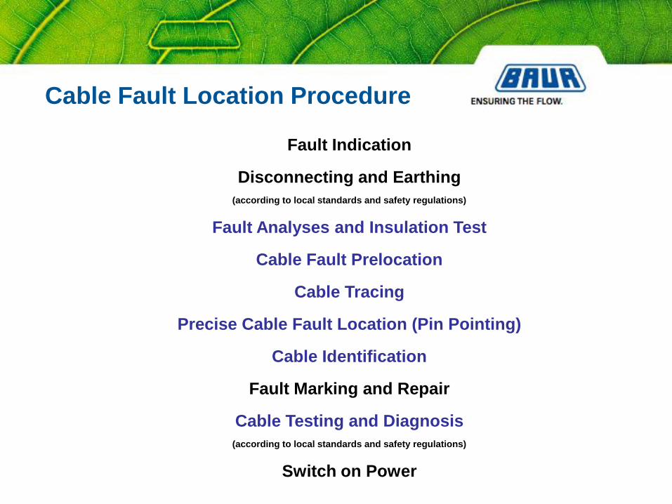
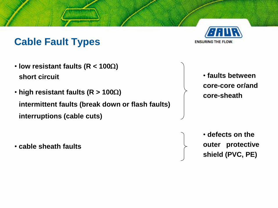
Cable Fault Types
• high resistant faults (R > 100W)
intermittent faults (break down or flash faults)
interruptions (cable cuts)
• faults between
core-core or/and
core-sheath
• cable sheath faults
• defects on the
outer protective
shield (PVC, PE)
short circuit
• low resistant faults (R < 100W)

Cable Fault Location Procedure
Fault Indication
Disconnecting and Earthing
(according to local standards and safety regulations)
Fault Analyses and Insulation Test
Cable Fault Prelocation
Cable Tracing
Precise Cable Fault Location (Pin Pointing)
Cable Identification
Fault Marking and Repair
Cable Testing and Diagnosis
(according to local standards and safety regulations)
Switch on Power

Methods of Cable Fault Prelocation
Method Fault Characteristics
Impulse Reflection Method high Ω – faults (e.g. cable cuts), low Ω – faults
Secondary Impulse Method/ high Ω – faults, intermittent faults
Multiple Impulse Method
Impulse Current Method high Ω – faults, intermittent faults(long cables)
Decay Method intermittent faults(breakdown voltage higher than 32kV)
Burn Down Techniques high Ω – faults, intermittent faults
Bridge Measurement high Ω –faults cable sheath faults, low Ω – faults
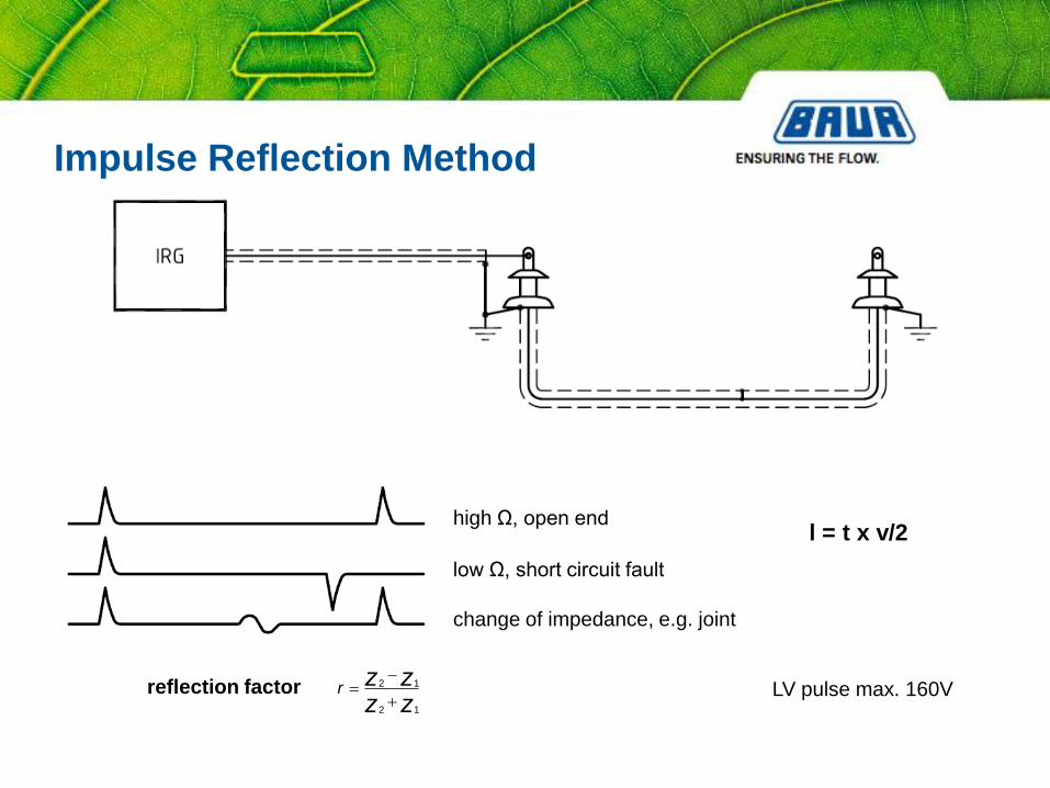
Impulse Reflection Method
l = t x v/2high Ω, open end
low Ω, short circuit fault
change of impedance, e.g. joint
LV pulse max. 160Vr z zz z
2 1
2 1
reflection factor
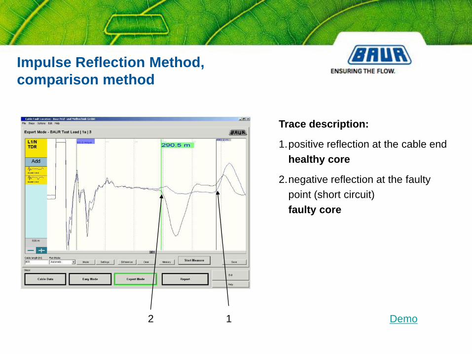
Impulse Reflection Method,
comparison method
Trace description:
1.positive reflection at the cable end
healthy core
2.negative reflection at the faulty
point (short circuit)
faulty core
12 Demo

l = t x v/2
Secondary Impulse Method - SIM

First measurement: positive reflection of the cable end
Second measurement: negative reflection from the arcing fault
Demo
Secondary Impulse Method - SIM

12345
TCL positive reflection of the far cable end (total cable length)
1 – 5 5 echograms of the arcing fault are recorded
Multiple Impulse Method - MIM
(advanced SIM)
TCL

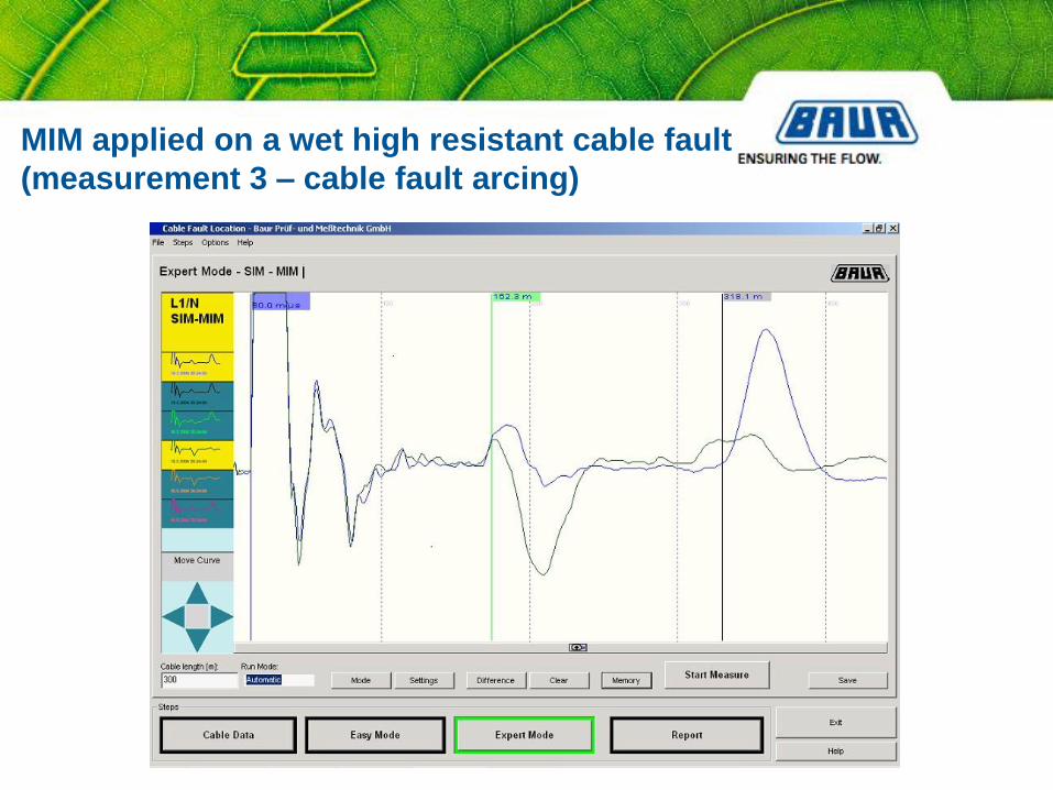
MIM applied on a wet high resistant cable fault
(measurement 1 – cable fault not yet arcing)

MIM applied on a wet high resistant cable fault
(measurement 2 – cable fault not yet arcing)
MIM applied on a wet high resistant cable fault
(measurement 3 – cable fault arcing)

MIM applied on a wet high resistant cable fault
(measurement 4 – cable fault arcing)

MIM applied on a wet high resistant cable fault
(measurement 5 – cable fault no more arcing, extinguished)

DC Application of MIM (advanced SIM)

Time Domain Reflectometer IRG 3000

IRG 3000 with 15“ stand alone monitor

The unique Multiple Impulse Method – MIM
ensures highest performance.
Fully automatic measuring sequences and fully automatic setting of all
measuring parameters assure most efficient and successful cable fault
location.
Fully automatic setting of the measuring cursors allows fully automatic
assessment of the fault distance in meters.
200 MHz real time sampling rate leads to highest accuracy of 0,1% and
highest resolution of 0,1 m.
Worldwide unique features IRG 3000
Measuring ranges from 10 m up to several 100 km and a memory for
more than 100 000 echograms enable universal application.
Windows 2000 Multilanguage allows worldwide software translations and
ensures max. comfort for operators.
Simultaneous display of up to 8 measurement traces provides highest
performance and comfort in comparisons with old measuring results.
Worldwide unique features IRG 3000

Time Domain Reflectometer IRG 2000
Features
• portable, easy to use
• interactive menu-guidance
• operated via knob and function keys
• battery operated
• measuring range up to 65 km (213,000 ft)
• measuring input voltage proof up to 400 V
• printer connection via RS 232
• memory up to 100 echogramms
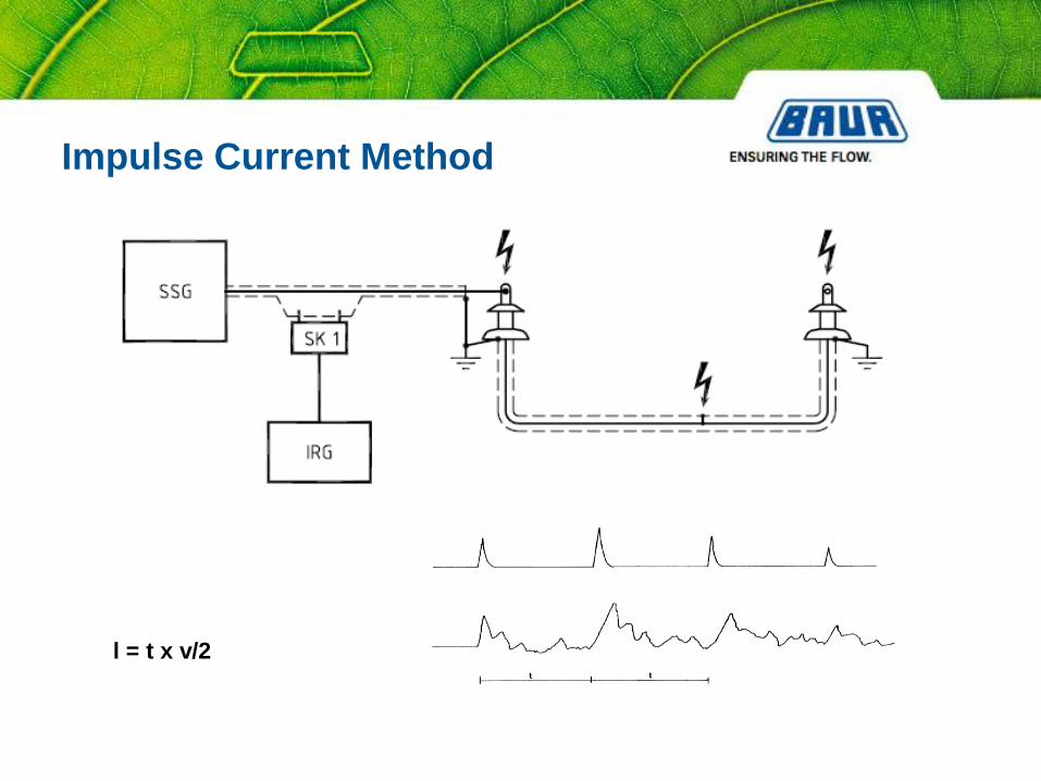
l = t x v/2
Impulse Current Method
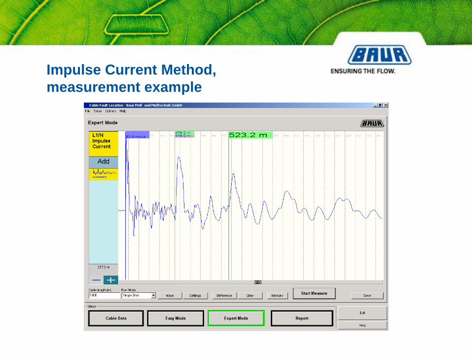
Impulse Current Method,
measurement example

PHG/
PGK
intermittent fault
break down fault
l = t x v/4
Decay Method
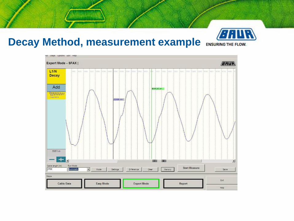
Decay Method, measurement example

Fault distance from cable end
Differential Impulse Method
Differential Decay Method

The bridge is in balance if both measuring
points a) and b) have the same value. The
galvanometer shows a value of zero.
The measuring points a) and b) have the same value if:
If R4 is an unknown resistance Rx, the value Rx is defined:
1
3
2
4
RR
RR
4
2
1
3RRR
R
xRR R
R 2 3
1
Bridge Method (Wheatstone)

The distance to the cable fault point is:
α: Scale division of measuring ten turn potentiometer (000,0....999,0)
with one auxiliary line and constant cross section
Bridge Method (Murray)

with two auxiliary lines and constant cross section
The distance to the cable fault point is:
a: Scale division of measuring ten turn potentiometer (000,0....999,0)
Bridge Method (Glaser)

Shirla
Measuring Bridge

Fault Indication
Disconnecting and Earthing
(according to local standards and safety regulations)
Fault Analyses and Insulation Test
Cable Fault Prelocation
Cable Tracing
Precise Cable Fault Location (Pin Pointing)
Cable Identification
Fault Marking and Repair
Cable Testing and Diagnosis
(according to local standards and safety regulations)
Switch on Power
Cable Fault Location Procedure

1.Galvanic connection
2. Inductive connection
with current clip on
device
3.Inductive connection
with frame antenna
cable
search coil
cable
Important:
correct positioning
of transmitter a > 10m
Cable Tracing

1. Minimum Method 2. Maximum Method 3. Depth Measurement
according to the
Minimum Method
Cable Tracing (TG + UL + SP or CL 20)

Locator Set
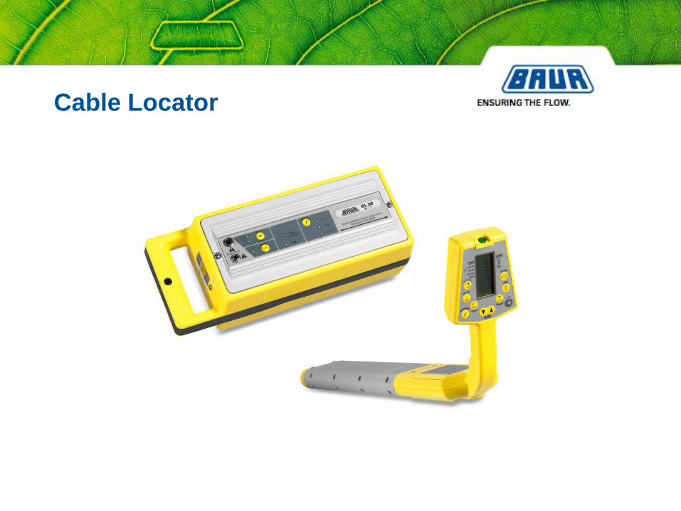
Cable Locator

Fault Indication
Disconnecting and Earthing
(according to local standards and safety regulations)
Fault Analyses and Insulation Test
Cable Fault Prelocation
Cable Tracing
Precise Cable Fault Location (Pin Pointing)
Cable Identification
Fault Marking and Repair
Cable Testing and Diagnosis
(according to local standards and safety regulations)
Switch on Power
Cable Fault Location Procedure

Acoustic Fault Location

Propagation Time Measurement,
pick up of magnetic and acoustic signal

Acoustic Fault Location at Manholes

• Distance indication in m
• Acoustic and magn. Pick up
• High noise suppression
• Manhole feature
• Multi receiver UL
• Light weight
• whether proof
• digital backlit display
Pin Pointing Set UL and BM

shirla
Shirla Cable sheath fault locator
(H.V. DC source)
1 cable sheath
2 shield
3 conductor
4 cable sheath fault
5 receiver with earth gradiant voltage
pick up
6 receiving signal (bi-directional)
Cable Sheath Fault Location

Cable Sheath Fault Location
shirla

• Cable and cable sheath testing
– up to 10kV
• Fault prelocation / Measuring bridge
- up to 10kV
• Fault pinpointing / step voltage method
- up to 10 kV
Shirla, Cable Test and Fault location system

Fault Indication
Disconnecting and Earthing
(according to local standards and safety regulations)
Fault Analyses and Insulation Test
Cable Fault Prelocation
Cable Tracing
Precise Cable Fault Location (Pin Pointing)
Cable Identification
Fault Marking and Repair
Cable Testing and Diagnosis
(according to local standards and safety regulations)
Switch on Power
Cable Fault Location Procedure
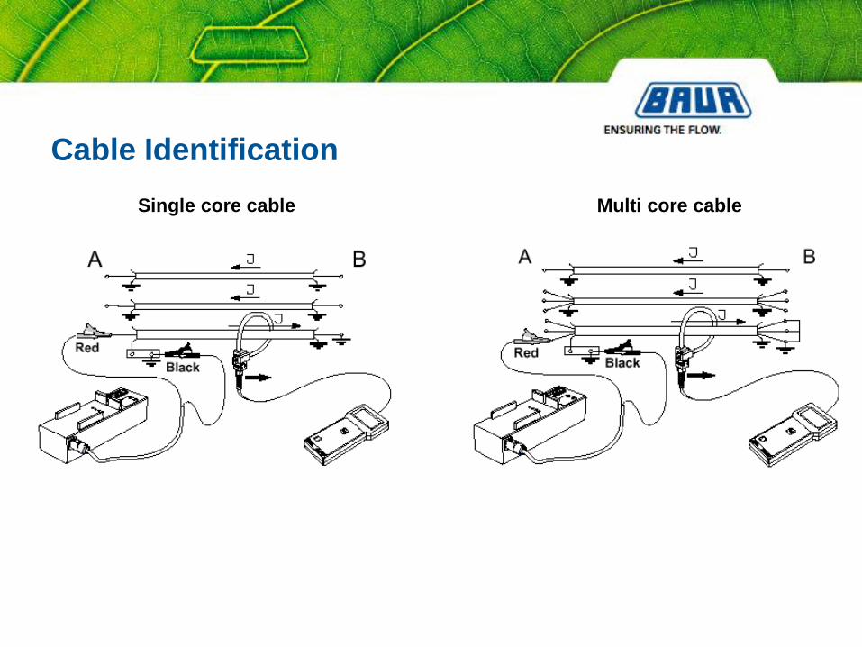
Single core cable Multi core cable
Cable Identification

• Flexible Rogowsky coil
• Single and 3-core cables
• Reliable signal acquisition
via digital analysis of
direction, amplitude and
synchronisation
Cable Identification Instrument
KSG 100

Cable testing, prelocation
and pin-pointing
Test voltage up to 5 kV
Pulse voltage up to 4 kV
Energy up to 1000 J
Fault location system for low voltage networks
STG 600 / 1000

Cable testing, prelocation
and pin-pointing
Voltage range 8/16 kV
adjustable in 0,1 kV steps
Energy 1000J
Weight ~85 kg
Fault location system for medium voltage networks
Syscompact 2000M

Cable testing, prelocation
and pin-pointing
Voltage range 8/16/32 kV
step less adjustable
Energy up to 2100 J
IRG 2000
Fault location system for medium voltage networks
Syscompact 2000 / 32 kV portable version

Cable testing, prelocation
and pin-pointing
Voltage range 8/16/32 kV
step less adjustable
Energy up to 2100 J
IRG 2000
Fault location system for medium voltage networks
Syscompact 2000 / 32 kV portable version with wheels

Cable testing, prelocation
and pin-pointing
Voltage range 8/16/32 kV
step less adjustable
Energy up to 2100 J
IRG 2000
Fault location system for medium voltage networks
Syscompact 2000 / 32 kV

Cable testing, prelocation
and pin-pointing
Voltage range 8/16/32 kV
step less adjustable
Energy up to 2100 J
IRG 3000
Fault location system for medium voltage networks
Syscompact 3000

TRANSCABLE
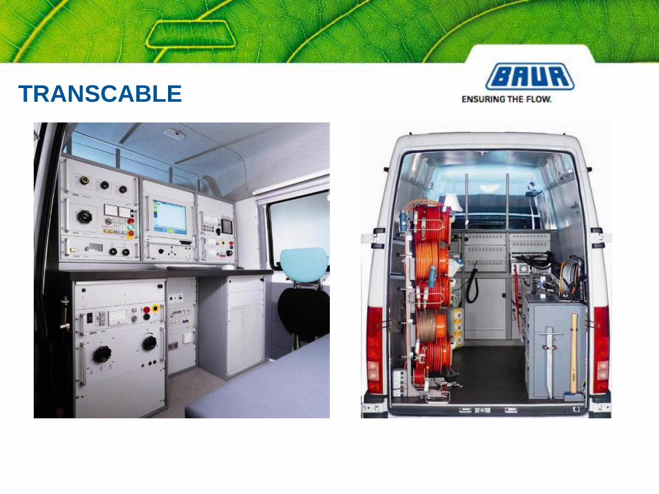
TRANSCABLE

TRANSCABLE
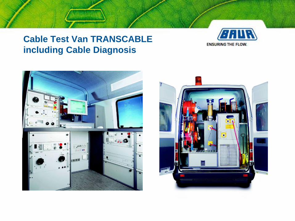
Cable Test Van TRANSCABLE
including Cable Diagnosis

Thousand’s of BAUR Cable fault location systems
are in daily use all over the world.
60 years of experience.
References
Stadtwerke
Saarbrücken AG