calibration for thermal paint chemistry - unsw canberra - school
TRANSCRIPT

United States Patent [19] Fukasawa
[54] METHOD AND APPARATUS FOR SEQUENTIAL PRODUCT PROCESSING WITH LIMITED PRODUCI‘ BAR CODE READING
[75] Inventor: Yoshihito Fukasawa, Yokohama, Japan
[73] Assignee: Kabushiki Kaisha Toshiba, Kawasaki, Japan
[21] Appl. No.: 167,193
[22] Filed: Mar. 11, 1988
[30] Foreign Application Priority Data Mar. 19, 1987 [JP] Japan ................................ .. 62-65141
[51] Int. Cl.5 ............................................ .. G06F 15/46 [52] US. Cl. .................................. .. 364/468; 235/375;
364/ 478 [58] Field of Search ...... .. 364/468, 478, 200 MS File,
364/900 MS File; 235/375, 383, 385
[56] References Cited U.S. PATENT DOCUMENTS
4,332,012 5/1982 Sekine et al. ...................... .. 364/468 4,408,291 10/1983 Gunzberg et a1. .. 364/468 X 4,473,883 9/1984 Yoshida et al. ....... .. 364/468 X 4,564,913 1/1986 Yomogida et a1. . 364/468 X 4,646,245 2/ 1987 Prodel et al. . . . . . . . . . . . . . .. 364/468
4,654,512 3/ 1987 Gardosi ......................... .. 364/468 X
FOREIGN PATENT DOCUMENTS
0129853Al l/ 1985 European Pat. Off. . DE34063-~—-'
“25A1 8/1985 FedaRep. of Germany . 883620 12/ 1961 United Kingdom .
2049994A 12/ 1980 United Kingdom .
CARRYING ROBOT
COMPUTER 7%
4,930,086 May 29, 1990
Patent Number:
Date of Patent:
[11]
[45]
OTHER PUBLICATIONS
“7-Axis Robot Automates Manufacturing Work Cell”, Electronic Design, vol. 31, (1983), Nov., No. 23, Waseca, Minn., Denville, N.J., U.S.A., pp. 141-148. Kiyoji ASAI, “Development for NC to CIM,” Intelli gent Factory, a separate volume of Nikkei Mechanical, Nov. 24, 1986, pp. 22-30.
Primary Examiner-Joseph Ruggiero Attorney, Agent, or Firm-Foley & Lardner, Schwartz, Jeffery, Schwaab, Mack, Blumenthal & Evans
[57] ABSTRACT There is provided a method including a plurality of processes for processing intermediary products step wise by a plurality of processing units arranged at re spective processes, thus to manufactur products while carrying intermediary products or carriers for accom modating them therein. This method comprises the steps of reading discrimination codes attached to the intermediary products or carriers prior to the ?rst pro cess, and recording the discrimination codes thus read as basic information and recording processing informa tion in regard to the processings by the processing units at the respective processes in correspondence with the basic information. This method further comprises the step of selecting one processing unit from a plurality of processing units at the process of the next state on the basis of the processing information recorded. There is also provided an apparatus for implementing the above method, which includes supervisory control means for carrying out selective control of processing units. Thus, . a manufacturing method and an apparatus therefor ca pable of implementing efficient manufacturing process ing can be realized.
6 Claims, 15 Drawing Sheets
B11 13 E; a PROCESS 1 E1 1
'——'_ PROCESS 11 E1 151 i
—PROCESS 111 E1 E1 151 E i E1 E1 E1 —-—PROCES$ 1V

Sheet 1 of 15 4,930,086
I
" U.S. vPatent May 29,1990
FIG. PRIOR ART
fnocsss 1 G4 G3 02 CH CARRYING
I I!
PROCESS III
C 1
C4 C2 Cl
"a u; #- 1
.________________.___.___._____J
PROCESS 1V - I
’l d4 d3 d2
PRODUCTION
COMPUTER
d: l
g--''"——‘ SUPERVISORY
200 /


US. Patent May 29,1990 Sheet 3 of 15 4,930,086
I I I0 / I
|--~ CONTROLLER—- MOUNTER ~I | I
I (I20 CARRYING I CONTROLLER— PR'MARY ~I2
(24 ROBOT I CURE UNIT
PRODUCTIONY I I {I30 SUPERVISOR I SECONDARY ._ COMPUTER I I Ir‘ ‘3°NTR°'-LER_ CURE UNIT '3 I I | I :3 (I40 I4) I COMPUTER ____1 CONTROLLER- BONDER
| :_”'I | I f ‘I II | {I50 I I I 7_ I I I I I-CONTROLLERr- BONDER ~15
I
I I I I60 I'——J I ( READER I I L~ CONTROLLER-— BONDER ~I6
I | I I 4 I I (I70 F" " ' | I L-- CONTROLLER - BONDER ~I7
I I l I I I L-- CONTROLLER- STORAGE ~I8 I I I MOLDING L‘ —————————————————————— -' UNIT ~|9

US. Patent May 29 1990 Sheet 4 of 15 4,930,086
FIG.4A vFIG.4B
FIG. 6
M 5 mm W
~ N x \ 27
i.
R R R R f ,w w M w W.
N N N N
o o o 0 U B B B B U
2 2/ 6/ % 2 Hum UH B§nU H. U Q?? U U
5
(U 2 B U

US. 0 Patent 4,930,086 May 29, 1990 Sheet 5 of 15
READING OF I DISCRIMINATION CODE
I 2 DIE
BONDING
I 3 CURE
sTANDBY
I 4 PRIMARY
CURE i _
5 SECONDARY CURE
I 6 BONDER
' LAYOUT
. I ‘
l I " - I I
BONDING lo BONDING l3 BONDING BONDING STANDBY sTANDBY STANDBY STANDBY
I I I I LOADER LOADER LOADER LOADER UNIT OF II UNIT OF l4 UNIT OF UNIT OF BONDER BONDER BONDER BONDER
I I I I UNLOADER UNLOADER UNLOADER UNLOADER UNIT OF I2 UNIT OF [5 uNIT OF UNIT OF BONDER BONDER BONDER BONDER
I I I J
I9 STORAGE

US. Patent May 29,1990 , Sheet 6 of 15 4,930,086
FIG .~ 7
28 I14 \ ,-|4c|
BB 9222 221%? E 1
14b \22
FIG.8A 4 FIG.8B
23 28v P2222599“ / 22~?
22
FIG. 86 FIG. 80
NO. OF VACANT COMPLETION OF _/_ AREAS — 2 PROCESSING
* @J ‘g1 28 2 28
22 22


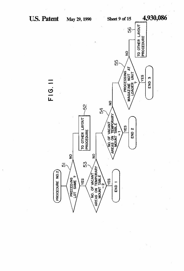
US. Patent May 29,1990 Sheet 9 of 15 4,930,086
wmznwoomm w om
OZ
mm mjm? Enos vm
mmDQwQOmE mm/ 595 5:5 oh
02
mm mw> oz ozEwumE N .02 mmDawoomm

US. Patent May 29,1990 4 Sheet 10 of 15 ‘4,930,086 FIG.I2
PROCEDURE NO.3
PRECEDING LOT SAME ?
62 PROCESSING
MAGAZINE NOT AT LOADER UNIT
'?
TO OTHER LAYOUT 63 PROCEDURE “'
FIG.I3
PROCEDURE NO. 4
PRECEDING LOT SAME ‘.7
TO OTHER LAYOUT ~72 PROCEDURE
PROCESSING MAGAZINE NOT AT
LOADER UNIT
TO LAYOUT PROCEDURE NO. 3


US. Patent May 29, 1990 Sheet 12 of 15 4,930,086
MEDQMQOWE PDO><|_ mmIFO Oh
mm mm\
w .02 wmDQwoOmm

U.S._ Patent May 29, 1990 Sheet 13 0f 15 4,930,086
mmDDmUOmm EDGE: @MIHO OP
\ @9
mg
mm;
OZ
OZ mmaowoomm m9
1 N01! 595 $16 oh
mm; F2302 >m<m0m 2MB. 20 N62 mmDomoOmm


1
METHOD AND APPARATUS FOR SEQUENTIAL PRODUCT PROCESSING WITH LIMITED
PRODUCT BAR CODE READING
BACKGROUND OF THE INVENTION
This invention relates to a method and an apparatus for manufacturing target products by processing units arranged at a plurality of manufacturing processes and, more particularly, to a method and an apparatus for manufacturing products capable of supervising or con trolling carrying of intermediary, or semi-manufactured or processed products in order to efficiently allot or assign intermediary products to processing units. The manufactures of various products including
semiconductor devices are conducted with a plurality of manufacturing processes being combined. While carrying intermediary products via these processes, their assembling works are conducted. For instance, a method of manufacturing semiconductor devices com prises a series of processes, e.g., a die bonding process for mounting semiconductor components or elements on the lead frame, a cure process for setting resin used in the die bonding, a wire bonding process for connect ing electrodes of the semiconductor components and leads of the lead frame using wires, a molding process for sealing wire-bonded regions using resin in the form of_ package, a cure process for setting the sealed resin by heating, and a bend process for bending leads projected from the resin, etc. For this reason, such an apparatus for manufacturing semiconductor devices is constituted that processing or manufacturing units, e. g., a mounter, a wire bonder, a molding unit,‘ a cure unit, and a bend
_ unit, etc. are arranged in succession from the upstream side of a carrying path for intermediary products. To the processing units at respective processes, carriers in which a plurality of lead frames on which unprocessed intermediary_products are mounted are accommodated are carried or conveyed. By the load of the carriers, lead frames are taken one by one. Thus, predetermined processings will be conducted. FIG. 1 is a block diagram showing a conventional
example of a manufacturing apparatus in which process ing units are arranged at a plurality of manufacturing processes, respectively as described above. This manu facturing apparatus includes four processes labeled I, II, III and IV: at the process I, four processing units a1, a2, a3 and a4 are disposed; at the process II, two processing units b1 and b; are disposed; at the process III, four processing units c1, c2, c3 and 04 are disposed; and at the process IV, four processing units d1, d2, d3 and d4 are disposed. In this case, the processing units disposed in the same process carry out the same processing. The processing units at the respective processes are con nected to a production supervisory computer 200. Thus, information indicative of output or the number of prod ucts, quality and working condition, etc. of respective units are delivered to the production supervisory com puter 200. From the production supervisory computer 200, various instructions, e.g., kind of articles or goods to be processed, lot name, quantity, and processing condition, etc. are delivered every processes, and thus these units are controlled in response thereto. The inter mediary products are carried and alloted to one pro cessing unit of the groups of units at respective pro cesses with they being as they are or they being accom modated in carriers in order of the processes I, II, III and IV. Thus, predetermined manufactured processings
20
25
30
40
45
50
55
65
4,930,086 2
are implemented thereto. In this case, it is necessary to collate the kind of articles to which the production supervisory computer 200 gives an instruction for pro cessing with the kind of articles that respective process ing units process. For this reason, travel sheets or indi cation labels, e.g., magnetic cards, etc. are attached on intermediary products or carriers, and readers for auto matically reading them and/ or keyboards for arti?cially inputting information read therefrom are provided at respective processing units. Accordingly, for example, when an intermediary product or carrier is carried from the process I to the process II and the manufacturing processing is then implemented thereto, information indicative of kind of article or lot of the intermediary product or carrier processed is sent to the production supervisory computer 200. In response to this signal, the production supervisory computer 200 produces an in struction to transfer the intermediary product or carrier to the process III. Thus, the intermediary product or carrier is alloted or assigned to one of processing units C1, C2, C3 and C4 at the process III. Then, at these processing units C1, C2, C3 and C4 the indication label of the intermediary product or carrier carried is read. Thus, when the kind of the intermediary product or carrier is in correspondence with the kind of article alloted, the processing is initiated. Such an allocation has been conventionally carried out arti?cially. However, with the conventional manufacturing
method and apparatus, the following problems occur: (1) Every time the kind or lot of the intermediary
product is changed or exchange of the carrier occurs, communication with the production supervisory com puter is required. Thus, the communication frequency becomes high, resulting in the possibility that an errone ous communication occurs.
(2) Since it is required to read the indication label every processing at respective processes, the reading frequency is high. Thus, there is apt to occur a circum stances such that reading is impossible due to the stain or missing or the indication label or the trouble of card reader, with the result that the system becomes con fused.
(3) Where input of information of the kind of the article is arti?cially conducted, an erroneous input is likely to occur.
(4) Since the communication frequency becomes high and a large quantity of indication labels are required in the production of a large number of kinds and a small quantity, the above-mentioned troubles to are likely to occur, with the result that it takes much labor and time for their recovery.
(5) Since allocation of processing units within one process is arti?cially conducted, it is difficult to conduct an efficient allocation in consideration of the switching frequency of kind of article and/or the arrangement time for the processing unit. As just described above, the conventional manufac
turing method and apparatus have the problems that since indication labels indicative of kind of article, lot, or the like are read at respective processes, and thus the production ,supervisory computer supervises or con trols carrying on the basis of this information, troubles are likely to occur and the improvement in the produc tion efficiency is hindered.

4,930,086 - process can be supervised by the computer, an efficient
3 SUMMARY OF THE INVENTION
An object of this invention is to provide manufactur ing method and apparatus capable of reducing the read ing frequency and communication frequency, and of carrying out an ef?cient processing. The above object is achieved by a method of manu
facturing products, including a plurality of processes for processing intermediary products stepwise by a plurality of processing units disposed at respective pro cesses to manufacture products while carrying the in termediary products or carriers for accommodating intermediary products therein, the method comprising the steps of: reading discrimination codes attached to the intermediary products or the carriers prior to the ?rst process; recording the discrimination codes thus read as basic information and recording processing information in regard to the processings by the process ing units at the respective processes in correspondence with the basic information; and selecting one processing unit from the plurality of processing units at the process of the next stage on the basis of the processing informa tion recorded. The above object is also achieved by an apparatus for
manufacturing products in which a plurality of process ing units are arranged at a plurality of processes for processing intermediary products stepwise to manufac ture products while carrying the intermediary products or carriers for accommodating the intermediary prod ucts therein, the apparatus comprising: read means for reading discrimination codes attached to the intermedi‘ ary products or the carriers prior to the ?rst process; and supervisory control means for recording the dis crimination codes thus read by the read means as basic information and recording processing information pro cessed by the processing units at respective processes in correspondence with the basic information, thus to select one processing unit from the plurality of process ing units at the process of the next stage on the basis of the information recorded.
Since this invention employs a scheme to read the discrimination codes as the basic information prior to the ?rst process to record processing information from the respective processing units in correspondence with the discrimination codes, thus to select one processing unit to be processed from those at a process of the next stage by‘ these information, various advantages are pro vided as follows:
(1) A reader for reading discrimination codes or a key board for inputting discrimination codes, or the like
O
20
25
35
40
45
every processing unit within the production process ‘ becomes unnecessary, with the result that the apparatus is simpli?ed.
(2) Troubles due to an erroneous operation in the discriminative reading, degradation of the discrimina tion code, an error by an operator, etc. do not occur, thus preventing the responsibility from being lowered.
(3) It is unnecessary to conduct a communication with a host computer in regard to the discrimination codes every time the intermediary product or carrier moves, with the result that the communication fre quency is reduced and the responsibility is improved.
(4) This apparatus effectively functions also by manu ally or arti?cially conducting a carrying instead of the automatic carrying system to add the function of input ting the result of carrying from the human system.
(5) Since the selection of the processing unit from the group of units having the same function within one
60
65
4
layout permitting the arrangement time, wait time, etc. to be minimized can be conducted on the real time basis.
‘ BRIEF DESCRIPTION OF THE DRAWINGS
FIG. 1 is a block diagram showing a conventional manufacturing apparatus; FIG. 2 is a block diagram showing an embodiment of
a manufacturing apparatus according to this invention; FIG. 3 is a block diagram showing another embodi
ment of a semiconductor manufacturing apparatus ac cording to this invention; FIGS. 4(A) and 4(B) are perspective views showing
the entirety of the magazine and a part thereof, respec tively; ‘
FIG. 5 is a block diagram showing the tracking posi tions in the semiconductor manufacturing apparatus; FIG. 6 is a plan view showing the arrangement of a
cure unit and a wire bonder in the semiconductor manu facturing apparatus; FIG. 7 is a plan view showing the wire bonder in the
semiconductor manufacturing apparatus; FIGS. 8(A) to 8(D) are plan views showing how the
wire bonder changes; FIG. 9 is a sequence diagram of the wire bonder; and FIG. 10 through FIG. 18 are tlowcharts for control
ling the layout of the wire bonder.
DETAILED DESCRIPTION OF THE INVENTION
This invention will be explained in more detail with reference to preferred embodiments shown. FIG. 2 is a block diagram showing the outline of an
embodiment according to this invention. A process I in which processing units a1, a3, a3 and a4 for carrying out the processing of the ?rst stage are disposed, a process 11 in which processing units b1 and b; for carrying out the processing of the second stage are disposed, a pro cess III in which processing units 01, c2, c3 and 04 for carrying out processing of the third stage are disposed, and a process IV in which processing units d1, d1, d3 and d4 for carrying out the processing of the fourth stage are disposed are arranged in succession from the upstream side to the downstream side. The intermediary product is subjected to predetermined processings while being carried from the upstream side (process I) to the down stream side (process IV) of a carrying path 1 with the intermediary product being accommodated in a carrier 2. In this sequence, various processes are conducted up to the ?nal assembling process. A computer 7 makes a judgement on the basis of information of the discrimina tion code 3 attached to the outer surface of the carrier 2 to send a signal to a carrying robot 6, to thereby con duct such a carrying. A discrimination code 3 is indi cated in a suitable form, e.g., a bar code, etc. in order to individually supervise or control the carrier 2. This code 3 is read by a reader 4 and is then decoded by a decoder 5, whereupon the code thus decoded is re corded into the memory unit of the computer 7 as the basic information. In this embodiment, the reader 4 is provided on the upstream side (entrance) of the ?rst process I of the plurality of processes I, II, III and IV to read the discrimination code 3 prior to the initiation of processings, thus to send information to the memory unit of the computer 7. At times subsequent thereto, processings are continued on the basis of the discrimina tion codes recorded in the memory unit. In addition, processing units at respective manufacturing processes
4,930,086 5
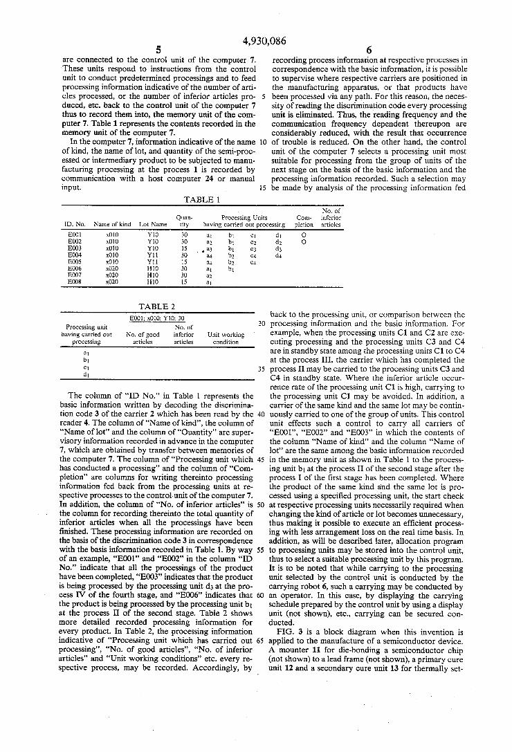
are connected to the control unit of the computer 7. These units respond to instructions from the control unit to conduct predetermined processings and to feed processing information indicative of the number of arti cles processed, or the number of inferior articles pro duced, etc. back to the control unit of the computer 7 thus to record them into, the memory unit of the com puter 7. Table 1 represents the contents recorded in the memory unit of the computer 7.
In the computer 7, information indicative of the name of kind, the name of lot, and quantity of the semi-proc essed or intermediary product to be subjected to manu facturing processing at the process 1 is recorded by communication with a host computer 24 or manual input.
6 recording process information at respective processes in correspondence with the basic information, it is possible to supervise where respective carriers are positioned in the manufacturing apparatus,‘ or that products have
5 been processed via any path. For this reason, the neces sity of reading the discrimination code every processing unit is eliminated. Thus, the reading frequency and the communication frequency dependent thereupon are considerably reduced, with the result that occurrence
10 of trouble is reduced. On the other hand, the control unit of the computer 7 selects a processing unit most suitable for processing from the group of units of the next stage on the basis of the basic information and the processing information recorded. Such a selection may
15 be made by analysis of the processing information fed
TABLE 1 No. of
Quan- Processing Units Com- inferior ID. No. Name of kind Lot Name tity having carried out processing pletion articles
E001 x010 Y10 30 in bi c1 d] 0 E002 x010 Y10 30 a; bi c2 d3 0 E003 x010 Y10 15 ' a3 b1 c3 d3 E004 x010 Yll 30 :14 b1 c4 (14 E005 x010 Yll 15 a4 b3 c4 E006 x020 H10 30 a1 b1 E007 x020 H10 30 a2 E008 x020 H10 15 al
TABLE 2 _ I _
EOO1_ ‘O10, Y10. 30 back to the processing unit, or comparison between the . . -""“_"'——" ' ' 3O processing information and the basic information. For
Processing unit No. of . .
having carried out No. of good inferior Unit working example’ when, the Processmg “mt? C1 aI_1d C2 are axe‘ processing articles articles condition cuting processing and the processing units C3 and C4
31 are in standby state among the processing units C1 to C4 b1 at the process III, the carrier which has completed the 3' process II may be carried to the processing units C3 and
l
The column of “ID No.” in Table 1 represents the basic information written by decoding the discrimina tion code 3 of the carrier 2 which has been read by the reader 4. The column of “Name of kind”, the column of “Name of lot” and the column of “Ouantity” are super visory information recorded in advance in the computer 7, which are obtained by transfer between memories of the computer 7. The column of “Processing unit which has conducted a processing” and the column of “Com pletion” are columns for writing thereinto processing information fed back from the processing units at re spective processes to the control unit of the computer 7. In addition, the column of “No. of inferior articles” is the column for recording thereinto the total quantity of inferior articles when all the processings have been finished. These processing information are recorded on the basis of the discrimination code 3 in correspondence with the basis information recorded in Table 1. By way of an example, “E001” and “E002” in the column “ID No.” indicate that all the processings of the product have been completed, “E003” indicates that the product is being processed by the processing unit d3 at the pro cess IV of the fourth stage, and “E006” indicates that the product is being processed by the processing unit b1 at the process II of the second stage. Table 2 shows more detailed recorded processing information for every product. In Table 2, the processing information indicative of “Processing unit which has carried out processing”, “No. of good articles”, “No. of inferior articles” and “Unit working conditions” etc. every re spective process, may be recorded. Accordingly, by
C4 in standby state. Where the inferior article occur rence rate of the processing unit C1 is high, carrying to the processing unit C1 may be avoided. In addition, a carrier of the same kind and the same lot may be contin uously carried to one of the group of units. This control unit effects such a control to carry all carriers of “E001”, “E002” and “E003” in which the contents of the column “Name of kind” and the column “Name of lot” are the same among the basic information recorded in the memory unit as shown in Table l to the process-_ ing unit b1 at the process II of the second stage after the process I of the ?rst stage has been completed. Where the product of the same kind and the same lot is pro cessed using a specified processing unit, the start check at respective processing units necessarily required when changing the kind of article or lot becomes unnecessary, thus making it possible to execute an efficient process ing with less arrangement loss on the real time basis. In addition, as will be described later, allocation program to processing units may be stored into the control unit, thus to select a suitable processing unit by this program. It is to be noted that while carrying to the processing unit selected by the control unit is conducted by the carrying robot 6, such a carrying may be conducted by an operator. In this case, by displaying the carrying schedule prepared by the control unit by using a display unit (not shown), etc., carrying can be secured con ducted. FIG. 3 is a block diagram when this invention is
applied to the manufacture of a semiconductor device. A mounter 11 for die-bonding a semiconductor chip (not shown) to a lead frame (not shown), a primary cure unit 12 and a secondary cure unit 13 for thermally set

4,930,086 7
ting a resin subject to bonding at the time of bonding for adhesively connecting or joining the lead frame and the semiconductor chip, four bonders 14, 15, 16 and 17 for wire-bonding electrodes of the semiconductor chip and leads of the lead frame, and a storage 18 for temporarily
. stocking the lead frame after wire bonding is completed in order to carry the lead frame to the molding unit 19 of the next process are successively arranged on the carrying path 1. These processing units are provided with controllers 11a, 12a, . . . 18a, respectively. The respective controllers 11a, 12a, . . . 18a are connected to
the computer 7 for supervising or controlling the dis crimination code and the processing information to conduct a control for allocation to processing units. Accordingly, the computer 7 records, into the memory unit, the processing information fed back from the re spective controllers 11a, 12a, . . . 180. On the other
hand, the reader 4 for reading the discrimination code of the intermediary product is connected to the com puter 7. Thus, the discrimination code from the reader 4 is recorded into the memory unit of the computer 7 as basic information. Also in this embodiment, the process ing information from the controllers 11a, 12a, . . . 18a are recorded in correspondence with the basic informa tion in the same manner as in the above-mentioned embodiment. While the computer 7 controls a carrying robot 20 for carrying an intermediary product to an allotted processing unit, its drive is controlled by a production supervisory computer 24 serving as a host computer. In this embodiment, the intermediary prod uct is mounted on a lead frame 21 as shown in FIG. 4(A). A large number of lead frames 21 are carried or conveyed on the carrying path 1 each lead frame 21 being accommodated into a magazine 22 serving as a carrier. In this case, as shown in FIG. 4(B), a plurality of step portions 22a are oppositely formed on the inner side surface of the magazine 22. The lead frame 21 is carried with it being supported by the respective step portions 22a. On the upper surface of the magazine 22, a discrimination code 23 indicated by a bar code, etc. is attached. This discrimination code 23 is read by the reader 4. Reading such a discrimination code 23 is con ducted upstream of the mounter 11 for die-bonding which is the manufacturing process of the ?rst stage or at the entrance of the mounter 11. In the con?guration stated above, the system having the following function is assembled into the computer 7.
(1) Carrying control of the magazine 22 (2) Tracking supervision of the magazine 22 (3)‘ Communication of production information with
the group of units at respective processes (4) Communication with the production supervisory computer
FIG. 5 shows the manufacturing processing of the magazine and tracking positions at which standby state is required for the manufacturing processing. Where reading the discrimination code of the magazine 22 by the reader 4 is at the tracking position of No. 1, the tracking position at the storage 18 is No. 19. Thus, 19 tracking positions are necessary in total. Accordingly, memory areas corresponding to at least 19 columns for the processing information corresponding to one dis crimination code are provided in the memory unit of the computer, in which recording and/or supervision of all the processing information are conducted. As an exam ple of this recording, a discrimination code 23 of a va cant magazine 22 is read by the reader 4 as the process ing information at the tracking position No. 1. This
30
45
60
65
8 information is recorded into the ?rst column of the tracking Table (Table 3) in the memory unit corre sponding to the basic information obtained from the discrimination code.
TABLE 3 Mount Cure Bonding
Discrirni- Tracking processing processing processing nation code position information information information
E005 1 E004 2 xx E003 3 xxxx E002 4 xxxx xx
E001 5 xxxx xxx
D050 18 xxxx xxxx xxx
D049 19 xxxx xxxx xxxxx
When the magazine 22 is then carried to the mounter 11, the processing information is recorded into thesec 0nd column of the tracking Table. When the die-bond ing by the mounter 11 is completed and the magazine 22 is carried to the standby position for curing, the process ing information is recorded into the third column of the tracking Table. In the same manner as stated above, at times subsequent thereto, by recording the processing information in succession, the supervision of the maga zine is carried out. Accordingly, not only the necessity of reading discrimination codes at respective processes for manufacturing processing is eliminated, but also processing information are recorded every tracking position, to thereby change them to the data base with the discrimination code being as a key, thus making it possible to expand the function as follows:
(1) Grasp of working achievement of individual pro cessing units
(2) Grasp of inferior article occurrence rate in the individual processing units
(3) Grasp of output or yield every lot (4) Grasp of time at which production starts or ends
with every lot or process (5) Con?rmation of name of kind, name of lot, the number of products, the number of good article, the number of inferior articles, the processing start time/ end time, and result of start check
(6) Efficient allocation of the magazine to four bond ers 14, 15, 16 and 17
An actual example of the above function (6) will be described. FIG. 6 shows the arrangement of the pro cessing units at the cure process and the wire bonding process. The primary cure unit 12 and the secondary cure unit 13 are adjoiningly provided. On both the sides of these units, a loader 25 and an unloader 26 are dis posed. Magazine is delivered from the unloader 26 to four bonders 14, 15, 16 and 17. Reference numeral 27 denotes a save area for placing the magazine 22 in a standby state when all the bonders 14, 15, 16 and 17 are executing processing. For one curing operation, three magazines 22 are processed at the same time. Three magazines 22 are taken or carried out from the left side of the unloader 26 to the cure positions of P1, P1 and P3 thereof and are then supplied to the bonder in order of P3, P2 and P1. In this embodiment, the bonders 14, 15, 16 and 17 of the same structure are used. Such structure will be described with reference to
FIG. 7 by taking an example of the bonder 14. At the central portion of a body 14a, a bonding head 14b for carrying out wire-bonding is provided. On the upstream