call manager express
DESCRIPTION
Dezvoltare personala.TRANSCRIPT

1
Call Manager Express

2

3
Introduction to Call Manager Express
IOS-based call processing software
Can control VOIP and POTs lines and trunks
Runs completely independent of a Call Manager Server
Able to perform many of the services that a Call Manager can provide.
Centralizes most data and voice functions of the local network to a single platform.
Provides a means to ensure efficient use of bandwidth via QoS
Cisco’s Call Manager Express is a completely self-contained call control and VoIP device management
system capable of running on a number of Cisco’s intermediate to higher-end routers. They give smaller
locations many of the same key call management features that a full-blown Call Manager can provide
including the ability to connect to POTS lines and VoIP trunking and provide dial tone to both digital and
analog devices. There is absolutely no need for a Call Manager to be present in the network for CME to
work.
CME also gives the added benefit of centralizing all data and voice functions to a single device. Since the
CME portion of the router can also be programmed completely via the CLI, there is no requirement for the
administrator to learn a new configuration method.
4
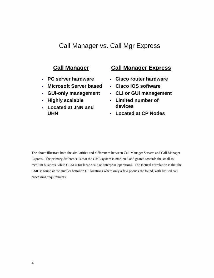
Call Manager vs. Call Mgr Express
Call Manager
• PC server hardware• Microsoft Server based• GUI-only management• Highly scalable• Located at JNN and
UHN
Call Manager Express
• Cisco router hardware• Cisco IOS software• CLI or GUI management• Limited number of
devices• Located at CP Nodes
The above illustrate both the similarities and differences between Call Manager Servers and Call Manager
Express. The primary difference is that the CME system is marketed and geared towards the small to
medium business, while CCM is for large-scale or enterprise operations. The tactical correlation is that the
CME is found at the smaller battalion CP locations where only a few phones are found, with limited call
processing requirements.

5
CME Call Path in JNN System
HUB Node
UA1 JNN UA2 JNN
CP Node 1 CP Node 2CP Node 2CP Node 1
HUB
UA 1 UA 2
Routes to Hub and Inter-UA
Route to JNN, secondary Inter-UA
Intra-UA Route
The CME routers are found exclusively in the battalion nodes of the JNN system. As the name suggests,
these are generally designated to be employed at the battalion level. A common misconception for the use
of CME on the battalion nodes has been that it is simply there to enable intrasite phone calls during a
network outage. There are actually several important reasons to have it – no need to register with a
particular JNN, an independent dial plan, minimized downtime during network outages, and localization of
the phone’s image file.
The only path that a CP Node typically has in the network will be over a highly-latent satellite connection.
By having all device registration and management functions, as well as several dial plans with routes to
intra-brigade peers the CP Node has little to no reliance on an external call management device.

6
CME Functional Requirements
Minimum Requirements
CME-enabled IOSCME-capable platformFirmware for phones
Optional Files
Music on Hold file(MOH)CME-GUI files
The only file that is actually needed to run CME on a router, is a CME-enabled IOS. Check the
current Configuration Management buildouts for the IOS used for each router.
The only reason that the phone firmware is needed is in the case where a phone is being used for
the first time in a network and is running the wrong version of firmware. For that reason, it is always a
good idea to have the firmware files loaded into the flash memory of the CME router.
If you wish to make available music on hold for the devices off of the CME router, then an audio file
named music-on-hold.au must reside in the flash memory of the router. A default file is provided with the
software, but any audio file of type .au or .wav can be used, as long as it is renamed music-on-hold.au.
Besides using the command line interface typically used to configure all Cisco routers, it is
possible to administer all the telephony functions of the router via a web GUI interface. It is provided in an
archived file of type .tar and the proper command must be entered into the command line interface in order
to properly upload and extract the files into their proper locations on the CME router. This command is
archive tar /xtract tftp://IP_Addr/filename.tar flash:
The file name will include versioning information that should match the version of IOS being run.
For example, on a 2600 router, if c2600-advipservicesk9-mz.123-11.T5.bin is being run as the IOS, then
cme-123-11T.tar should be the tar file uploaded using the above command.

7
Cisco Devices – CME/CPN
7940, 7940G
7960, 7960G
7910, 7910+SW
ATA – 186/188
The phones currently issued to the JNN, CPN and Hub nodes are the 7940G series of phones. However, all of the above listed phones have been utilized in the JNN network at some point and will continue to be used as units maintain stockage of them. 7940(G) & 7960(G) - The 7940 & 7960 IP phones, along with their global (G model) variants are executive level telephones that provide advanced features to the user. The 7940 provides two line capability, while the 7960 provides up to 6. In addition to the calling features, both support XML services which can allow directory information, as well as stock info, weather, and just about any other interactive information that can be programmed via XML. 7910 – A lower end phone commonly used in general-use areas where advanced features are not a requirement. The +SW version of the phone includes an 100MB connection which allows a PC/laptop to be connected off the backend, requiring only a single Cat5 line to be run to the area. Has programmable softkeys and a two-line LCD display. ATA 186/188 - These models of Analog Telephone Adapter are a smaller version of the VG-224/248’s in that they provide for the connection of 2 analog (FXS) lines to the IP network.
8
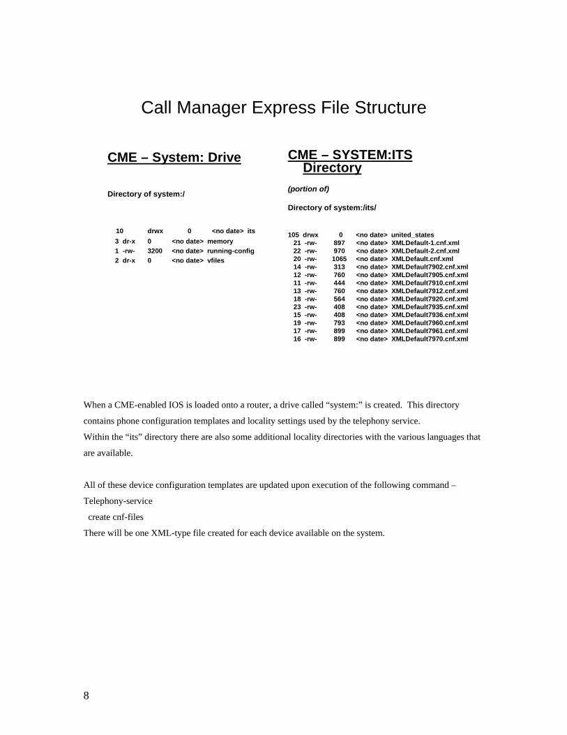
Call Manager Express File Structure
CME – System: Drive
Directory of system:/
10 drwx 0 <no date> its3 dr-x 0 <no date> memory1 -rw- 3200 <no date> running-config2 dr-x 0 <no date> vfiles
CME – SYSTEM:ITS Directory
(portion of)
Directory of system:/its/
105 drwx 0 <no date> united_states21 -rw- 897 <no date> XMLDefault-1.cnf.xml22 -rw- 970 <no date> XMLDefault-2.cnf.xml20 -rw- 1065 <no date> XMLDefault.cnf.xml14 -rw- 313 <no date> XMLDefault7902.cnf.xml12 -rw- 760 <no date> XMLDefault7905.cnf.xml11 -rw- 444 <no date> XMLDefault7910.cnf.xml13 -rw- 760 <no date> XMLDefault7912.cnf.xml18 -rw- 564 <no date> XMLDefault7920.cnf.xml23 -rw- 408 <no date> XMLDefault7935.cnf.xml15 -rw- 408 <no date> XMLDefault7936.cnf.xml19 -rw- 793 <no date> XMLDefault7960.cnf.xml17 -rw- 899 <no date> XMLDefault7961.cnf.xml16 -rw- 899 <no date> XMLDefault7970.cnf.xml
When a CME-enabled IOS is loaded onto a router, a drive called “system:” is created. This directory
contains phone configuration templates and locality settings used by the telephony service.
Within the “its” directory there are also some additional locality directories with the various languages that
are available.
All of these device configuration templates are updated upon execution of the following command –
Telephony-service
create cnf-files
There will be one XML-type file created for each device available on the system.

9
IP Phone Firmware Naming Examples
P00303020214.bin7940G/7960GP00305000301.sbin7940/7960Cmterm_7936.3-3-5-0.bin7936P00503010100.bin7935cmterm_7920.3.3-01-08.bin7920 WirelessS00103020002.bin7914 Exp. Module for 7960CP7912040000SCCP040701A.sbin7912GP00403020214.bin7910CP79050040000SCCP040701A.sbin7905GCP79020040000SCCP040701A.sbin7902ATA030100SCCP040211A.ZUPATA-186, ATA-188
FilenamePlatform
These are the only devices that are supported on the Call Manager Express platform in IOS version 12.3. If
using any of these devices within the CME network, the requisite firmware must be made available on the
router. There are two commands needed to point to these files –
tftp-server flash:P00303020214.bin
tftp-server flash:P00403020214.bin
tftp-server flash:P00503010100.bin
and within telephony-service:
load 7960-7940 P00303020214
load 7910 P00403020214
load 7935 P00503010100.bin

10
Notice that with the tftp-server command, the entire filename, including extension is needed. Within the
telephony service command, the extension is not needed for 7910, 7940, or 7960 phones, but any other
does need the extension.
The tftp-server command allows the router to be utilized as a tftp server, but only for the file(s) specified.
The load command specifies which devices will run off this router, and associates a firmware name with
the device.
11
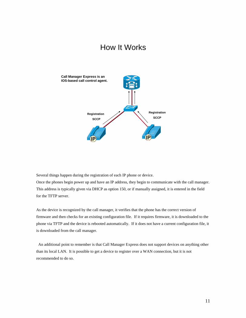
How It Works
Registration
SCCP
Registration
SCCP
Call Manager Express is an IOS-based call control agent.
Several things happen during the registration of each IP phone or device.
Once the phones begin power up and have an IP address, they begin to communicate with the call manager.
This address is typically given via DHCP as option 150, or if manually assigned, it is entered in the field
for the TFTP server.
As the device is recognized by the call manager, it verifies that the phone has the correct version of
firmware and then checks for an existing configuration file. If it requires firmware, it is downloaded to the
phone via TFTP and the device is rebooted automatically. If it does not have a current configuration file, it
is downloaded from the call manager.
An additional point to remember is that Call Manager Express does not support devices on anything other
than its local LAN. It is possible to get a device to register over a WAN connection, but it is not
recommended to do so.

12
Configuration Steps
Set IP Address on Telephony DeviceDHCP – Automatically set address
Turn on and Configure telephony-serviceCreate directory numbersApply directory numbers to devices
The basic requirements to initially configure the CME system is listed above and described on the next
several pages. These include the following steps:
1. Device IP Addressing – There are any number of ways to have a device acquire an IP address,
whether manually or automatically. The main requirements in any case are – IP Address, proper
subnet mask, proper gateway address and “Option 150” specifying the TFTP server that will
provide the CME configuration files.
2. Telephony-service – This is the global IOS command which sets system level CME parameters.
3. Directory Numbers – Always create directory numbers BEFORE configuring devices. Part of the
device configuration is binding one or more directory numbers to the phone.
4. Device Configuration – Very little is required to have a device completely register with the system
- a MAC address and the “button” command to set directory numbers for the phone.

13
Example - DHCP Server Settings
ip dhcp pool VOICEnetwork 22.230.40.254 255.255.255.192default-router 22.230.40.254option 150 ip 22.230.40.254
show ip dhcp binding
When any Cisco phone device boots, one of the first things it looks for is a DHCP server with which to
get its IP settings and also the Cisco Call Manager address. This is especially important to remember when
a device has either been booted for the first time or has recently had a factory reset performed on it. In
those cases, it is required to have both a DHCP server and a TFTP server available for the devices.
The settings above are the minimum settings needed by any Cisco device in order to get it to function. “IP
dhcp pool VOICE” creates a DHCP pool called “VOICE”, which is case-sensitive. The network command
describes the range of addresses that will be provided to a client. The default-router points to the gateway,
which in this case is also the CME router, but doesn’t always have to be the case. Option 150 is a setting
utilized by Cisco to identify the address of the TFTP server to the client device. It also will be the address
of the Call Manager, but again doesn’t always have to be the case. The device configuration file received
via TFTP will actually have the Call Manager address which the device will use to register.
The show command above will list any devices that have received an address from this DHCP server.
14
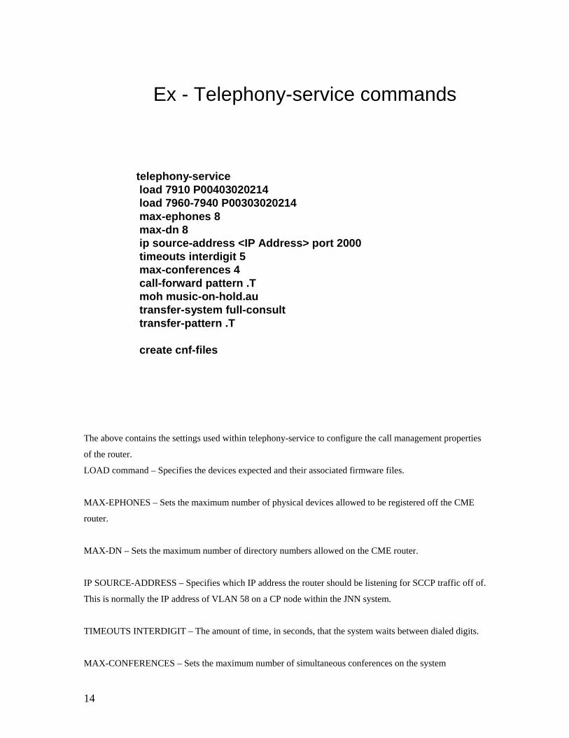
Ex - Telephony-service commands
telephony-serviceload 7910 P00403020214load 7960-7940 P00303020214max-ephones 8max-dn 8ip source-address <IP Address> port 2000timeouts interdigit 5max-conferences 4call-forward pattern .Tmoh music-on-hold.autransfer-system full-consulttransfer-pattern .T
create cnf-files
The above contains the settings used within telephony-service to configure the call management properties
of the router.
LOAD command – Specifies the devices expected and their associated firmware files.
MAX-EPHONES – Sets the maximum number of physical devices allowed to be registered off the CME
router.
MAX-DN – Sets the maximum number of directory numbers allowed on the CME router.
IP SOURCE-ADDRESS – Specifies which IP address the router should be listening for SCCP traffic off of.
This is normally the IP address of VLAN 58 on a CP node within the JNN system.
TIMEOUTS INTERDIGIT – The amount of time, in seconds, that the system waits between dialed digits.
MAX-CONFERENCES – Sets the maximum number of simultaneous conferences on the system

15
CALL-FORWARD PATTERN – In the case of the JNN CME’s all calls are forwarded.
MOH – Specifies the name of the music on hold file, stored in the root of the flash: drive. In this case it is
music-on-hold.au.
TRANSFER-SYSTEM – Sets the type of transfers allowed on the system – blind or full-consult
TRANSFER-PATTERN – Specifies which directory numbers that are allowed to transfer active calls. A
pattern of “.T” allows all extensions to make transfers.
CREATE CNF-FILES – This command is used to automatically create the default device configuration
files.
16
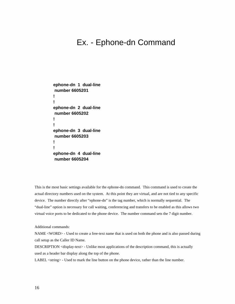
Ex. - Ephone-dn Command
ephone-dn 1 dual-linenumber 6605201
!!ephone-dn 2 dual-linenumber 6605202
!!ephone-dn 3 dual-linenumber 6605203
!!ephone-dn 4 dual-linenumber 6605204
This is the most basic settings available for the ephone-dn command. This command is used to create the
actual directory numbers used on the system. At this point they are virtual, and are not tied to any specific
device. The number directly after “ephone-dn” is the tag number, which is normally sequential. The
“dual-line” option is necessary for call waiting, conferencing and transfers to be enabled as this allows two
virtual voice ports to be dedicated to the phone device. The number command sets the 7 digit number.
Additional commands:
NAME <WORD> - Used to create a free-text name that is used on both the phone and is also passed during
call setup as the Caller ID Name.
DESCRIPTION <display-text> - Unlike most applications of the description command, this is actually
used as a header bar display along the top of the phone.
LABEL <string> - Used to mark the line button on the phone device, rather than the line number.

17
Ex. - Ephone Command
ephone 1mac-address <mac-address>type 7960button 1:1
!!ephone 2mac-address <mac-address>type 7960button 1:2
!!ephone 3mac-address <mac-address>type atabutton 1:3
!
The ephone command is used to associate a physical device (an ethernet phone) to directory numbers.
NOTE: If a phone has already been plugged in and is active on the system, it will automatically bind to the
first available ephone number. This can be seen when a phone displays the date and time, but no directory
number. The “show ephone summary” command may be run on the CLI to determine which ephone it has
bound to, by MAC address. The administrator still needs to perform the above commands and type in the
MAC address in order to fully register and bind a directory number to the device.

18
Call Processing - Internal
Call Setup -SCCP
Voice Traffic-RTP
Phone A calls Phone B
PHONE BPHONE A
Call Setup -SCCP
A call sequence within one CME router is quite simple. The phone dials the requested number and the
most specific match will be the directory number of the destination device. The same CME router handles
the call control for both devices and then hands the call off to the devices. The are two protocols involved:
SCCP – Skinny Call Control Protocol – Used primarily as the signaling method between a device and its
registered call manager or between to call managers. Only used during device registration, call setup and
call teardown.
RTP – Real-Time Transport Protocol – Used as the end-to-end transport mechanism for applications
passing real-time data, such as audio or video. Allows for time-stamping and packet sequencing to enable
the devices to reassemble the packets in the correct order.

19
Call Processing – CME to CME
Call Setup –H.323
Voice Traffic-RTP/H323/RTP
Phone A calls Phone B
PHONE B
6605301
22.230.44.199
PHONE A
6605201
22.230.40.199
dial-peer voice 66053 voipdescription Primary Route for calls to bn3preference 1destination-pattern 66053..session target ipv4:22.230.44.254codec g711ulawno vad
BN 3 CME
22.230.44.254
BN 2 CME
22.230.40.254
Call Setup -SCCP
Call Setup -SCCP
When phone A goes offhook and begins dialing, the BN 2 CME is continually attempting to match the
dialed digits with its most specific dial peer or directory number.
Once the caller dials the sequence of 67273, the CME has now narrowed the possibilities down to the
above dial peer. After the final digits are dialed and the requisite pause set by the “interdigit timeout”, the
directory number request is immediately sent to the session target, in this case BN3 CME for directory
resolution.
As the call is in progress between the WAN connection, the CME’s act as a sort of proxy for their
respective voice devices. The RTP voice data is converted to H.323 signaling to be passed between the
CME devices. Once received at the distant CME, the packet IP and UDP header’s are rewritten for
transmission for the device endpoint. The purpose of this conversion of RTP to H.323 is to take advantage
of the QoS features inherent within H.323 such as RSVP and priority queuing.

20
Ex. Dial Peers for JNN System
dial-peer voice 5 voipdescription Primary route to MSE to JNN1preference 1destination-pattern 5...... Standard route to MSE lines via session target ipv4:<UA JNN1 CCM IP> the main UA JNN.codec g711ulawno vad
!dial-peer voice 9993 voipdescription All NNXXXXX calls not matching more detailed go to HUB Routes 7 digit calls to the HUB.preference 1destination-pattern [2-9][2-9].....session target ipv4:148.22.246.29codec g711ulawno vad!dial-peer voice 9994 voipdescription All MYXXXXXXXX calls go to HUB Routes 10 digit calls to the HUB.preference 1destination-pattern [2-8][0-1]........session target ipv4:148.22.246.29codec g711ulawno vad
Ex. Dial Peers – Cont.
dial-peer voice 9995 voipdescription All 9YXMYXXXXXXXX calls go to HUB Allows NATO routing up to HUB CCM.preference 1destination-pattern 9[0-1].[2-8][0-1]........session target ipv4:148.22.246.29codec g711ulawno vad!dial-peer voice 9998 voipdescription All other calls go to hub for routingpreference 1destination-pattern .T Description self-explanatory. There are additional .T dial-peers, withsession target ipv4:<HUB CCM Address> different preferences (2,3,4,etc.) when additional default pathscodec g711ulaw are available.no vad
!dial-peer voice 66052 voipdescription RingAroundtheRosey prevention Each CPN now includes this dial-peer, pointing to its ownpermission none dialplan in order to prevent misdialing or non-registered phone huntstop directory numbers from leaving the local CME system.destination-pattern 66052..session target ipv4:<yourCME_IP>gatewaytimer receive-rtp 12000

21
These are several dial peers in the JNN CME systems that are common to all CMEs. Every BN node
directs any non-matched directory numbers to the Cisco Call Manager at the Unit Hub Node – which
includes 7, 10, NATO, and default match patterns. Any calls for the MSE system are sent to the primary
JNN for the BN node’s parent brigade. If this unit is task organized to another unit that has a JNN node, it
would need to be modified to go to its Call Manager.
Something to keep in mind with these dial peers and any others, for that matter, is they merely direct the
call to the call management system that most likely contains the directory number dialed. Call completion
will still follow the IP route to the actual IP-enabled device for call setup.
An additional function that the default dial-peer performs does not involve outbound calls, but inbound. It
ensures that the proper codec is used for call setup, which in this case is g.711. If this was not the case,
there would be the possibility that an inbound number would not match one of the dial peers and would use
the default “dial-peer 0” settings, which includes compression. Dial-peer 0 does not actually appear on the
router configuration and cannot be modified, which is why it is always important to include a default dial-
peer in your telephony configurations.

22
Ex. Dial Peers – Cont.
dial-peer voice 6605 voipdescription Primary Route for calls to UA1preference 1 This is one of the two entries needed destination-pattern 6605[0-1].. to go directly to brigade JNNs.session target ipv4 :<UA JNN1 CCM IP>codec g711ulawno vad
dial-peer voice 66053 voipdescription Primary Route for calls to bn3preference 1 This entry is typical for routing to destination-pattern 66053.. another battalion CP node in the samesession target ipv4:<CME IP of BN3> brigade.codec g711ulawno vad
These dial peers enable the CME to directly negotiate with the call control device handling the directory
number being called. There is always the possibility that a brigade combat team will be deployed in a stand
alone configuration. This ensures that all units normally organized under the brigade will be reachable with
no reconfiguration required.
During deployments where the BN node is organized under a different UA, additional dial peers may be
added to reach the dial peers within that UA’d network. It is not recommended to delete the existing dial
peers.
23
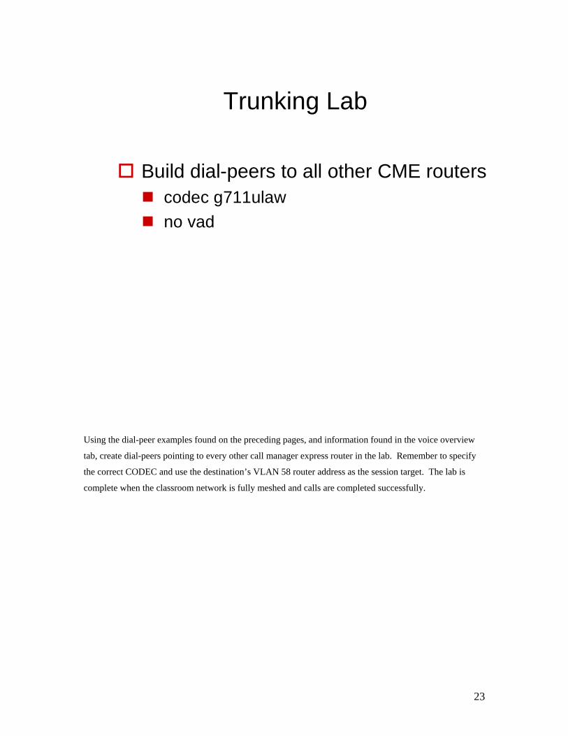
Trunking Lab
Build dial-peers to all other CME routerscodec g711ulawno vad
Using the dial-peer examples found on the preceding pages, and information found in the voice overview
tab, create dial-peers pointing to every other call manager express router in the lab. Remember to specify
the correct CODEC and use the destination’s VLAN 58 router address as the session target. The lab is
complete when the classroom network is fully meshed and calls are completed successfully.

24
Show Commands
shows all calls in progressshow voice call active brief
Shows all configured dial-peers, to include ephone-dn’sshow dial-peer voice summary
Shows more detailed information related to CMEshow telephony-service all
shows current CME-related configuration infoshow telephony-service
shows summary information – useful for getting MAC address info.show ephone summary
shows detailed information about all registered telephony devicesshow ephone
DescriptionCommand
These show commands are useful specifically for the operation and troubleshooting of a Call Manager
Express system.
25
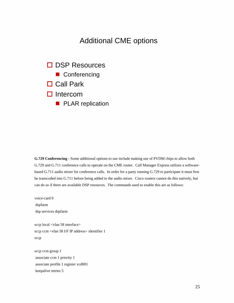
Additional CME options
DSP ResourcesConferencing
Call ParkIntercom
PLAR replication
G.729 Conferencing - Some additional options to use include making use of PVDM chips to allow both
G.729 and G.711 conference calls to operate on the CME router. Call Manager Express utilizes a software-
based G.711 audio mixer for conference calls. In order for a party running G.729 to participate it must first
be transcoded into G.711 before being added to the audio mixer. Cisco routers cannot do this natively, but
can do so if there are available DSP resources. The commands used to enable this are as follows:
voice-card 0
dspfarm
dsp services dspfarm
sccp local <vlan 58 interface>
sccp ccm <vlan 58 I/F IP address> identifier 1
sccp
sccp ccm group 1
associate ccm 1 priority 1
associate profile 1 register xcd001
keepalive retries 5

26
dspfarm profile 1 transcode
codec g711ulaw
codec g711alaw
codec g729ar8
codec g729abr8
codec gsmfr
codec g729r8
maximum sessions 12
associate application SCCP
Call Park – In order to park calls, a process that allows you to put a call on hold and then retrieve the call
from any phone onsite, you must create an “ephone-dn” specifically set to be of type park. If an active call
is parked, then anyone who dials the call park number can retrieve the held call. The following is an
example using number 1234 as the call park retrieval number:
ephone-dn 20 {dual-line}
number 1234
park-slot
PLAR – Private Line Automatic Ringdown serves as a form of hotline phone which when applied to a
phone allows it only to call a single specified directory number. The following example shows that phone
number 10, with directory number 5000 will only be allowed to call directory number 4000 when it goes
off-hook:
ephone-dn 10 dual-line
number 5000
intercom 4000 barge-in
ephone 10
button 1:10
autoline 1
27
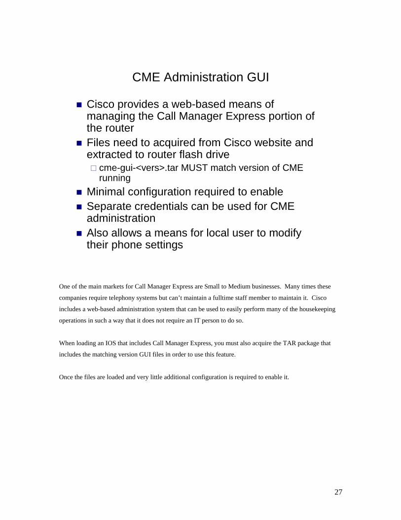
Cisco provides a web-based means of managing the Call Manager Express portion of the routerFiles need to acquired from Cisco website and extracted to router flash drive
cme-gui-<vers>.tar MUST match version of CME running
Minimal configuration required to enableSeparate credentials can be used for CME administrationAlso allows a means for local user to modify their phone settings
CME Administration GUI
One of the main markets for Call Manager Express are Small to Medium businesses. Many times these
companies require telephony systems but can’t maintain a fulltime staff member to maintain it. Cisco
includes a web-based administration system that can be used to easily perform many of the housekeeping
operations in such a way that it does not require an IT person to do so.
When loading an IOS that includes Call Manager Express, you must also acquire the TAR package that
includes the matching version GUI files in order to use this feature.
Once the files are loaded and very little additional configuration is required to enable it.
28
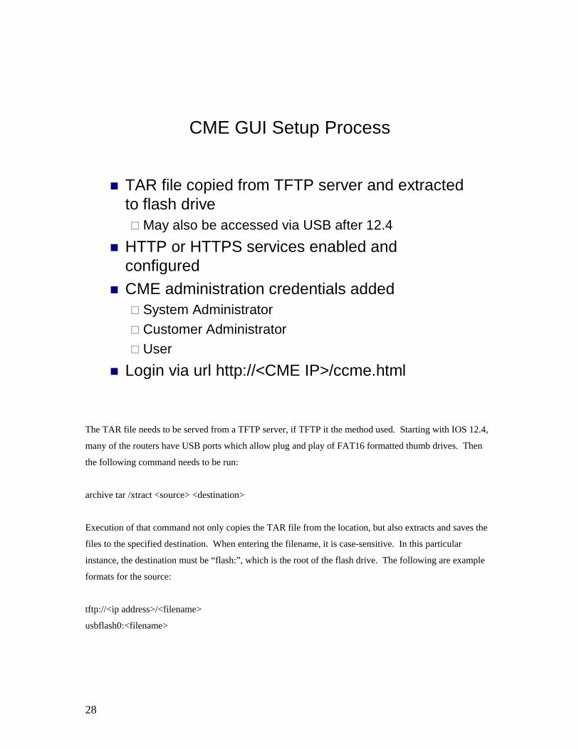
CME GUI Setup Process
TAR file copied from TFTP server and extracted to flash drive
May also be accessed via USB after 12.4HTTP or HTTPS services enabled and configuredCME administration credentials added
System AdministratorCustomer AdministratorUser
Login via url http://<CME IP>/ccme.html
The TAR file needs to be served from a TFTP server, if TFTP it the method used. Starting with IOS 12.4,
many of the routers have USB ports which allow plug and play of FAT16 formatted thumb drives. Then
the following command needs to be run:
archive tar /xtract <source> <destination>
Execution of that command not only copies the TAR file from the location, but also extracts and saves the
files to the specified destination. When entering the filename, it is case-sensitive. In this particular
instance, the destination must be “flash:”, which is the root of the flash drive. The following are example
formats for the source:
tftp://<ip address>/<filename>
usbflash0:<filename>

29
After verifying the GUI files are now in the flash directory, enter the following commands at the global
configuration prompt:
ip http server
ip http auth local
ip http path flash:
And these commands from the “telephony-service” command subset:
web admin system name <admin name> password <password>
dn-webedit
time-webedit
You may now login to the GUI via the url of http://<cme IP>/ccme.html
30
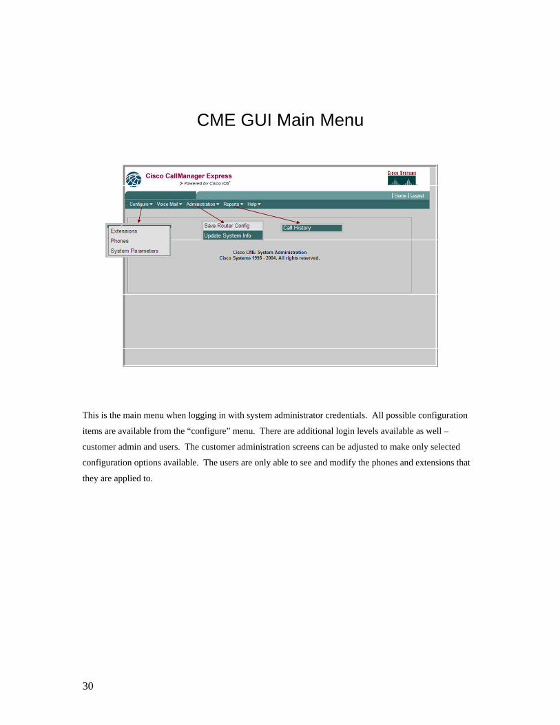
CME GUI Main Menu
This is the main menu when logging in with system administrator credentials. All possible configuration
items are available from the “configure” menu. There are additional login levels available as well –
customer admin and users. The customer administration screens can be adjusted to make only selected
configuration options available. The users are only able to see and modify the phones and extensions that
they are applied to.
31
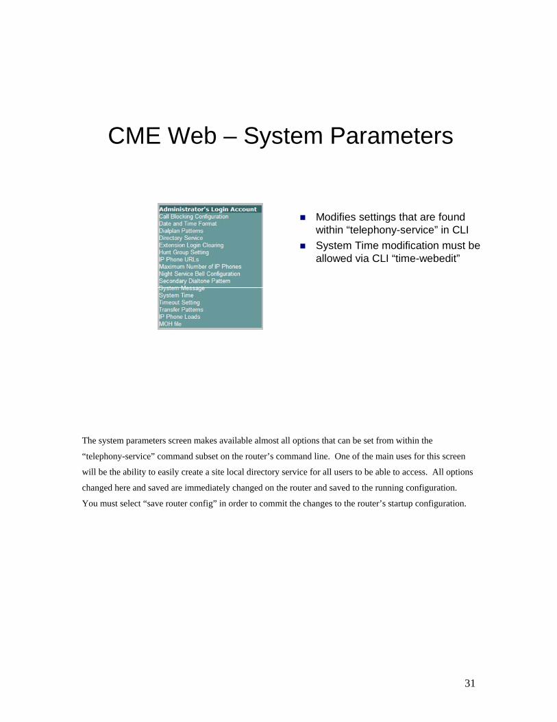
CME Web – System Parameters
Modifies settings that are found within “telephony-service” in CLISystem Time modification must be allowed via CLI “time-webedit”
The system parameters screen makes available almost all options that can be set from within the
“telephony-service” command subset on the router’s command line. One of the main uses for this screen
will be the ability to easily create a site local directory service for all users to be able to access. All options
changed here and saved are immediately changed on the router and saved to the running configuration.
You must select “save router config” in order to commit the changes to the router’s startup configuration.

32
CME Web - Extensions
The extensions screen corresponds to the “ephone-dn” command line set. This will allow you to add,
modify or delete directory numbers, which then may be assigned to one or more phone devices.
33
CME Web - Phones
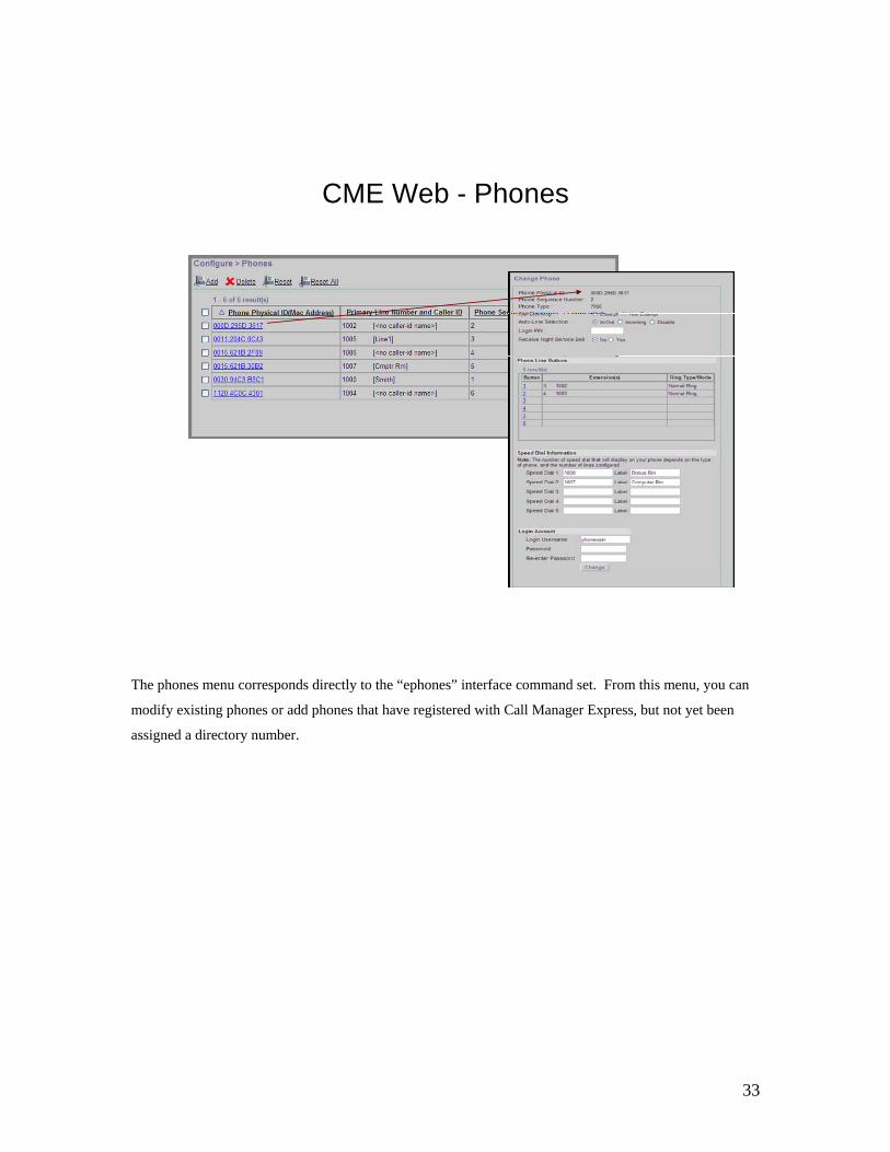
The phones menu corresponds directly to the “ephones” interface command set. From this menu, you can
modify existing phones or add phones that have registered with Call Manager Express, but not yet been
assigned a directory number.

34
CME Web – Call History Reports
Shows calls recently made to or from CME systemMemory buffer is adjustable in global CLI config
call-history-mib max-size <0-500>call-history-mib retain-timer <0-500> (in minutes)
The Call History screen provides only a small snapshot of calls that have been handled by the call manager
express system. It will show up to the last 500 minutes of calls, or a maximum of 500 calls within that
same time period. For more detailed and long term histories, a 3rd party plugin will be required.