calm water and seakeeping investigation for a fast … · calm water and seakeeping investigation...
TRANSCRIPT
11th International Conference on Fast Sea Transportation FAST 2011, Honolulu, Hawaii, USA, September 2011
Calm Water and Seakeeping Investigation for a Fast Catamaran
R. Broglia1, B. Bouscasse1, B. Jacob1, A. Olivieri1, S. Zaghi1 and F. Stern2
1CNR-INSEAN, The Italian Ship Basin, Rome, ITALY
2IIHR Hydroscience & Engineering, The University of Iowa, Iowa City, Iowa, USA
ABSTRACT In this paper calm water and in wave research activities on a high-speed displacement catamaran performed at CNR-INSEAN in collaboration with the IIHR are presented. The selected geometry is the DELFT-372 catamaran, for which a large database is in construction through a series of NICOP projects. Calm water activity was carried out for the analysis of the interference phenomena; resistance, trim and sinkage tests have been performed for both the monohull and the catamaran with several separation lengths and for a wide range of Froude numbers (Fr=0.1÷0.8). Experimental (inner and outer) wave cuts have been also acquired for selected separation lengths and Froude numbers. Seakeeping tests with transient, regular and irregular waves are performed. Preliminarily, comparison with the experimental results in regular wave carried out at DELFT have been done. Seakeeping transient tests allowed the identification of the Froude number of maximum response; once it has been determined, regular wave experiments were used to assess the role of the nonlinearities on the hull motions at that Fr: several steepness and wavelengths of the incident wave system were considered. The measurements collected are a valuable data base for both hydrodynamic studies of high speed catamaran and CFD validation. KEY WORDS Catamaran, interference, separation length dependency, seakeeping 1.0 INTRODUCTION The demand for high speed multihull vessels has strongly increased during last decades for both commercial and military purposes; in particular, catamaran configurations are very attractive because of their excellent performances with respect to speed, safety, resistance and transversal stability. As a consequence, a number of theoretical, experimental and numerical studies have been carried out in recent years. Insel and Molland (1992) highlighted catamarans hydrodynamic features experimentally and numerically by means of the thin ship hypothesis; the effect of the main demihull dimension and separation length on the overall resistance performance and running trim and sinkage at a wide range of Froude numbers (0:2 to 1:0) were provided. A similar analysis, applied to a broader set of hull forms, were conducted by Molland et al. (1996), whereas, Armstrong (2003) focused his effort to identify the different resistance
components. The influence of viscosity on the hydrodynamic behavior of a catamaran has been studied in Doctors (2003) by using a theoretical approach; the analysis was carried out in both deep and restricted water, for different demihull separations. The investigation of the effects of the separation distance on the resistance components was also carried out in Molland et al. (2004) and Millward (1992), by means of both experimental tests and theoretical approaches. More recently, a pure experimental analysis has been proposed by Souto-Iglesias et al. (2007); resistance, sinkage and trim, as well as inner and outer wave cuts were measured and an interesting correlation between the interference factor with wave cuts was highlighted.
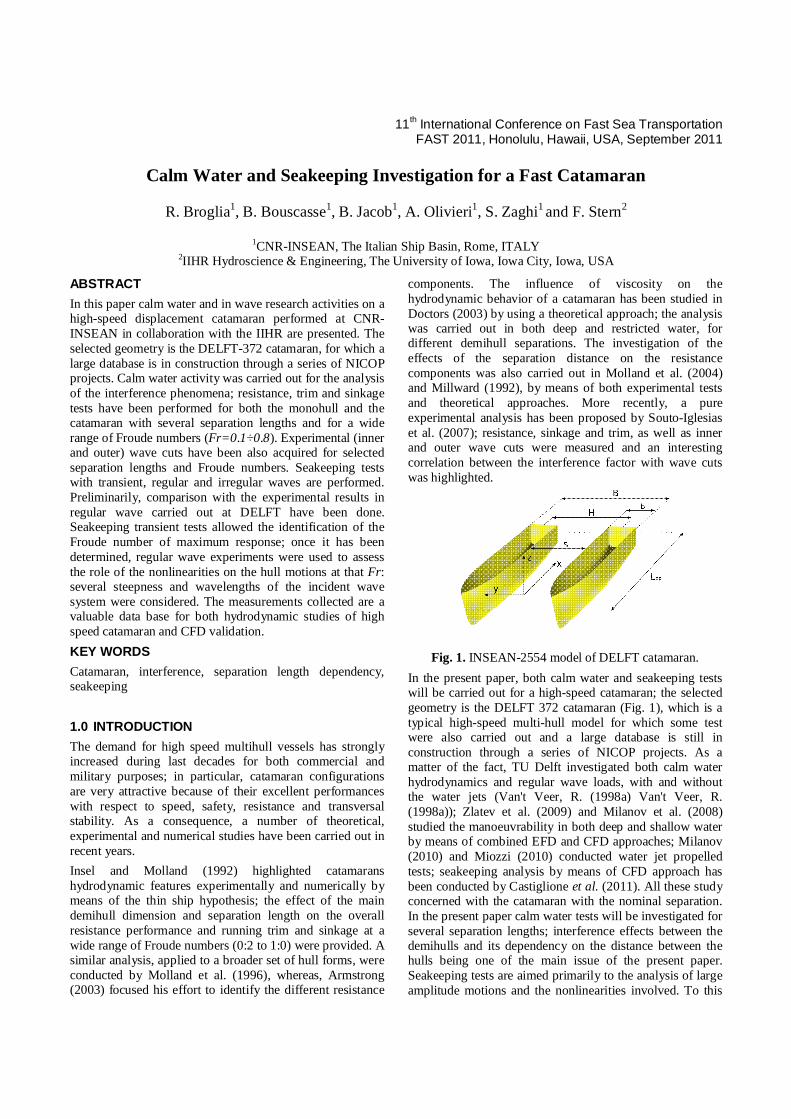
Fig. 1. INSEAN-2554 model of DELFT catamaran.
In the present paper, both calm water and seakeeping tests will be carried out for a high-speed catamaran; the selected geometry is the DELFT 372 catamaran (Fig. 1), which is a typical high-speed multi-hull model for which some test were also carried out and a large database is still in construction through a series of NICOP projects. As a matter of the fact, TU Delft investigated both calm water hydrodynamics and regular wave loads, with and without the water jets (Van't Veer, R. (1998a) Van't Veer, R. (1998a)); Zlatev et al. (2009) and Milanov et al. (2008) studied the manoeuvrability in both deep and shallow water by means of combined EFD and CFD approaches; Milanov (2010) and Miozzi (2010) conducted water jet propelled tests; seakeeping analysis by means of CFD approach has been conducted by Castiglione et al. (2011). All these study concerned with the catamaran with the nominal separation. In the present paper calm water tests will be investigated for several separation lengths; interference effects between the demihulls and its dependency on the distance between the hulls being one of the main issue of the present paper. Seakeeping tests are aimed primarily to the analysis of large amplitude motions and the nonlinearities involved. To this
aim transient tests have been conducted at several Froude numbers. The large measurements collected both in calm water and in waves) is a valuable data base for CFD validation, too. 2.0 EXPERIMENTAL SETUP In this section the experimental setup for both the calm water and the sea keeping tests is described. Calm water tests have been conducted in the CNR-INSEAN towing tank number 1, whose dimensions are: 470m13.5m6.5m, in length, width and depth, respectively. Seakeeping tests were performed in the basin 2 (220m9m3.6m), which is equipped with a flap wavemaker Kempf & Remmers, hinged at a height of 1.8m from the bottom. The main characteristics of the setups are given below, while a detailed description of the experiments (as well as the collection of all the measurements) can be found in Broglia et al. (2011a), Broglia et al. (2011b) and Bouscasse et al. (2011). A fiberglass geosym model of the DELFT-372 has been built (INSEAN model 2554); the main characteristics are given in Table 1, whereas the geometry is shown in Fig. 1. In order to stimulate turbulence, the model is equipped with a row of cylindrical studs of 4mm height and 3mm diameter, 30mm spaced, fitted on the model 70mm behind the bow profile. The same model has been used for both calm water and wave tests.
Table 1. INSEAN-2554 model: main dimensions. Dimension Symbol Value
Length between perpendiculars Lpp 3.00 m Beam overall B 0.94 m
Beam demihull b 0.24 m Distance between centre of hulls H 0.70 m
Draught T 0.15 m Displacement Δ 87.07 Kg
Vertical centre of gravity KG 0.34 m Longitudinal centre of gravity LCG 1.41 m
Pitch radius of gyration kyy 0.782m Moment of inertia for pitch I55 53.245 Kgm2
2.1 Resistance, trim and sinkage tests
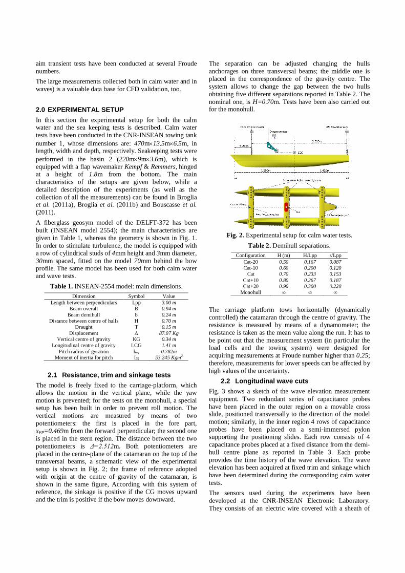
The model is freely fixed to the carriage-platform, which allows the motion in the vertical plane, while the yaw motion is prevented; for the tests on the monohull, a special setup has been built in order to prevent roll motion. The vertical motions are measured by means of two potentiometers: the first is placed in the fore part, xFP=0.469m from the forward perpendicular; the second one is placed in the stern region. The distance between the two potentiometers is Δ=2.512m. Both potentiometers are placed in the centre-plane of the catamaran on the top of the transversal beams, a schematic view of the experimental setup is shown in Fig. 2; the frame of reference adopted with origin at the centre of gravity of the catamaran, is shown in the same figure, According with this system of reference, the sinkage is positive if the CG moves upward and the trim is positive if the bow moves downward.
The separation can be adjusted changing the hulls anchorages on three transversal beams; the middle one is placed in the correspondence of the gravity centre. The system allows to change the gap between the two hulls obtaining five different separations reported in Table 2. The nominal one, is H=0.70m. Tests have been also carried out for the monohull.
Fig. 2. Experimental setup for calm water tests.
Table 2. Demihull separations. Configuration H (m) H/Lpp s/Lpp
Cat-20 0.50 0.167 0.087 Cat-10 0.60 0.200 0.120
Cat 0.70 0.233 0.153 Cat+10 0.80 0.267 0.187 Cat+20 0.90 0.300 0.220
Monohull ∞ ∞ ∞ The carriage platform tows horizontally (dynamically controlled) the catamaran through the centre of gravity. The resistance is measured by means of a dynamometer; the resistance is taken as the mean value along the run. It has to be point out that the measurement system (in particular the load cells and the towing system) were designed for acquiring measurements at Froude number higher than 0.25; therefore, measurements for lower speeds can be affected by high values of the uncertainty.
2.2 Longitudinal wave cuts Fig. 3 shows a sketch of the wave elevation measurement equipment. Two redundant series of capacitance probes have been placed in the outer region on a movable cross slide, positioned transversally to the direction of the model motion; similarly, in the inner region 4 rows of capacitance probes have been placed on a semi-immersed pylon supporting the positioning slides. Each row consists of 4 capacitance probes placed at a fixed distance from the demi-hull centre plane as reported in Table 3. Each probe provides the time history of the wave elevation. The wave elevation has been acquired at fixed trim and sinkage which have been determined during the corresponding calm water tests. The sensors used during the experiments have been developed at the CNR-INSEAN Electronic Laboratory. They consists of an electric wire covered with a sheath of
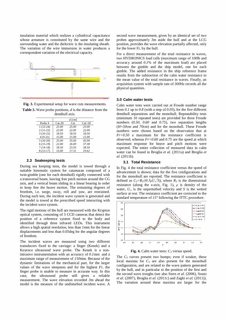
insulation material which realizes a cylindrical capacitance whose armature is constituted by the same wire and the surrounding water and the dielectric is the insulating sheath. The variation of the wire immersion in water produces a correspondent variation of the electrical capacity.
Fig. 3. Experimental setup for wave cuts measurements. Table 3. Wave probe positions, d is the distance from the
demihull axis. d [cm]
Probe # Cat-20 Cat Cat+20 1 (12-24) 25.00 25.00 25.00 2 (11-23) 22.00 22.00 22.00 3 (10-22) 18.50 18.50 18.50 4 (9-21) 15.00 15.00 15.00
5 (16-20) 25.00 35.00 45.00 6 (15-19) 22.00 26.69 37.38 7 (14-18) 18.50 23.50 28.50 8 (13-17) 15.00 17.31 19.62
2.3 Seakeeping tests
During sea keeping tests, the model is towed through a suitable kinematic system for catamaran composed of a twin-gimble (one for each demihull) rigidly connected with a transversal beam, leaving free pitch motion around the CG axis, and a vertical beam sliding in a linear bearing in order to keep free the heave motion. The remaining degrees of freedom, i.e. surge, sway, roll and yaw, are restrained. During each test, the incident wave system is generated and the model is towed at the prescribed speed interacting with the incident wave system. The rigid motions of the hull are measured with the Krypton optical system, consisting of 3 CCD cameras that detect the position of a reference system fixed to the body and identified through three infrared LEDs. This instrument allows a high spatial resolution, less than 1mm for the linear displacements and less than 0.05deg for the angular degrees of freedom. The incident waves are measured using two different transducers fixed to the carriage: a finger (Kenek) and a Keyence ultrasound wave probe. The Kenek is a non-intrusive instrumentation with an accuracy of 0.1mm and a maximum range of measurement of 150mm. Because of the dynamic limitations of the mechanical part, for the larger values of the wave steepness and for the highest Fr, the finger probe is unable to measure in accurate way. In this case, the ultrasound probe still gives a reliable measurement. The wave elevation recorded 3m ahead the model is the measure of the undisturbed incident wave. A
second wave measurement, given by an identical set of two probes approximately 3m aside the hull and at the LCG position, provides the wave elevation partially affected, only for the lower Fr, by the hull. For a direct measurement of the total resistance in waves, two HYDRONICS load cells (maximum range of 100lb and accuracy around 0.1% of the maximum load) are placed between the gimble and the ship model, one for each gimble. The added resistance in the ship reference frame results from the subtraction of the calm water resistance to the mean value of the total resistance in waves. Finally, an acquisition system with sample rate of 300Hz records all the physical quantities. 3.0 Calm water tests Calm water tests were carried out at Froude number range from 0.1 up to 0.8 (with a step of 0.05), for the five different demihull separations and the monohull. Repeatability tests (minimum 10 repeated tests) are provided for three Froude numbers (0.50, 0.60 and 0.75), two separation lengths (H=50cm and 70cm) and for the monohull. These Froude numbers were chosen based on the observation that at Fr=0.50 a maximum for the resistance coefficient is observed; whereas Fr=0.60 and 0.75 are the speed at which maximum response for heave and pitch motions were expected. The entire collection of measured data in calm water can be found in Broglia et al. (2011a) and Broglia et al. (2011b).
3.1 Total Resistance In Fig. 4 the total resistance coefficient versus the speed of advancement is shown; data for the five configurations and for the monohull are reported. The resistance coefficient is defined as CT=RT/(0.5ρU∞
2S), where RT is the dimensional resistance (along the x-axis, Fig. 1), ρ is density of the water, U∞ is the unperturbed velocity and S is the wetted surface at rest. The resistance coefficient are corrected to the standard temperature of 15° following the ITTC procedure.
Fig. 4. Calm water tests: CT versus speed.
The CT curves present two humps; even if weaker, these local maxima for CT are also present for the monohull configuration, and are related to the wave pattern generated by the hull, and in particular to the position of the first and the second wave troughs (see also Stern et al. (2006), Souto et al. (2007), Broglia et al. (2011c) and Zaghi et al. (2011)). The variation around these maxima are larger for the
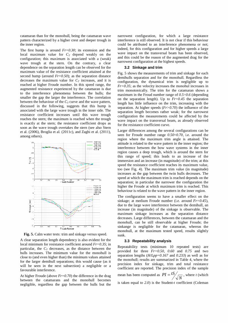
catamaran than for the monohull, being the catamaran wave pattern characterized by a higher crest and deeper trough in the inner region. The first hump is around Fr=0.30; its extension and the local maximum value for CT depend weakly on the configuration; this maximum is associated with a (weak) wave trough at the stern. On the contrary, a clear dependence on the separation length can be observed for the maximum value of the resistance coefficient attained at the second hump (around Fr=0.50); as the separation distance decreases the maximum value for CT increases, and it is reached at higher Froude number. In this speed range, the augmented resistance experienced by the catamaran is due to the interference phenomena between the hulls; the smaller the gap the larger the interference. The correlation between the behaviour of the CT curve and the wave pattern, discussed in the following, suggests that this hump is associated with the large wave trough in the inner side. The resistance coefficient increases until this wave trough reaches the stern; the maximum is reached when the trough is exactly at the stern; the resistance coefficient drops as soon as the wave trough overtakes the stern (see also Stern et al. (2006), Broglia et al. (2011c), and Zaghi et al. (2011), among others).
Fig. 5. Calm water tests: trim and sinkage versus speed.
A clear separation length dependency is also evident for the local minimum for resistance coefficient around Fr=0.35; in particular, the CT decreases, as the distance between the hulls increases. The minimum value for the monohull is close to (and even higher than) the minimum values attained for the larger demihull separations; this would cause (as it will be seen in the next subsection) a negligible or a favourable interference. At higher Froude (above Fr=0.70) the difference in the drag between the catamarans and the monohull becomes negligible, regardless the gap between the hulls but the
narrowest configuration, for which a large resistance interference is still observed. It is not clear if this behaviour could be attributed to an interference phenomena or not; indeed, for this configuration and for higher speeds a large wave impact on the transversal beam has been observed, and this could be the reason of the augmented drag for the narrowest configuration at the highest speeds.
3.2 Sinkage and trim Fig. 5 shows the measurements of trim and sinkage for each demihulls separation and for the monohull. Regardless the configuration, the dynamical trim is negligible up to Fr=0.35; as the velocity increases the monohul increases in trim monotonically. The trim for the catamaran shows a maximum in the Froud number range of 0.5÷0.6 (depending on the separation length). Up to Fr=0.45 the separation length has little influence on the trim, increasing with the separation. At higher speeds (Fr>0.70) the influence of the separation length becomes rather weak; for the narrowest configuration the measurements could be affected by the wave impact on the transversal beam, as already observed for the resistance coefficient curve. Larger differences among the several configurations can be seen for Froude number range 0.50÷0.70, i.e. around the region where the maximum trim angle is attained. The attitude is related to the wave pattern in the inner region; the interference between the bow wave systems in the inner region causes a deep trough, which is around the stern for this range of speed; this leads to an increase of the immersion and an increase (in magnitude) of the trim; at this speed the resistance coefficient reaches its maximum value, too (see Fig. 4). The maximum trim value (in magnitude) increases as the gap between the twin hulls decreases. The speed at which the maximum trim is reached depends on the separation; in particular the narrower the configuration the higher the Froude at which maximum trim is reached. This behaviour is related to the wave pattern in the inner region. The configuration seems to have a smaller effect on the sinkage; at medium Froude number (i.e. around Fr=0.45), due to the large wave interference between the demihull, an increase (in magnitude) of the sinkage is observable. The maximum sinkage increases as the separation distance decreases. Large differences, between the catamaran and the monohull, can be still observable at higher Froude; the sinkange is negligible for the catamaran, whereas the monohull, at the maximum tested speed, results slightly sunk.
3.3 Repeatability analysis Repeatability tests (minimum 10 repeated tests) are provided for three Fr=0.50, 0.60 and 0.75 and two separation lengths (H/Lpp=0.167 and 0.233) as well as for the monohull; results are summarized in Table 4, where the precision index for sinkage, trim and total resistance coefficient are reported. The precision index of the sample
mean has been computed as N
tSPI , where t (which
is taken equal to 2.0) is the Student-t coefficient (Coleman
and Steele, 2009), is the standard deviation and N is the number of repeated runs. In the table the percentage values related to the correspondent maximum value, are reported. In general, the analysis points out good repeatability for the experimental measurements of both the resistance coefficient and the trim; higher uncertainty is observed for the sinkage. Repeatability seems to be independent on both the speed and the distance between the hulls, whereas higher uncertainty is clearly observed for the monohull.
Table 4. Precision index summary. Quantity Fr Cat-20 Cat Monohull
Sinkage 0.50 2.04% 2.91% 6.01% 0.60 2.63% 3.41% 2.81% 0.75 1.31% 2.47% 5.53%
Trim 0.50 0.70% 1.30% 1.59% 0.60 0.63% 1.25% 0.62% 0.75 0.75% 1.23% 1.01%
CT 0.50 0.11% 0.21% 0.09% 0.60 0.09% 0.19% 0.06% 0.75 0.19% 0.13% 0.09%
3.4 Interference factor
Comparing the total resistance coefficients for the catamaran and the monohull (Fig. 4), it is evident that, for a wide range of speed, the drag experienced by the catamaran is larger than twice the monohull; the augmented resistance is due to the interference between the twin hulls. Its measure can be obtained from the interference factor defined as:
)(
)()(
)(
)()(
22M
T
MT
CT
MT
MT
CT
F RRR
CCCI
(1)
having denoted with M and C quantities concerning the monohull and the catamaran, respectively. Positive and negative interference correspond to situation where the interference between the twin hulls leads to a resistance increase (unfavourable interference) or decrease (favourable interference).
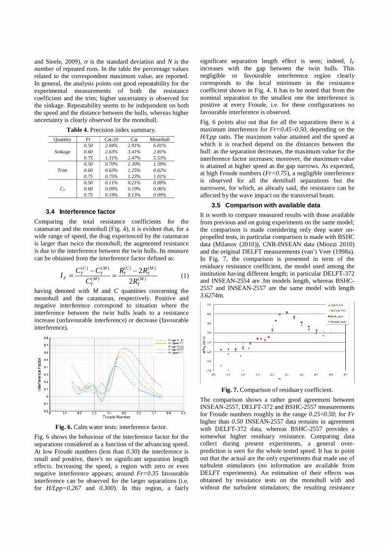
Fig. 6. Calm water tests: interference factor.
Fig. 6 shows the behaviour of the interference factor for the separations considered as a function of the advancing speed. At low Froude numbers (less than 0.30) the interference is small and positive, there's no significant separation length effects. Increasing the speed, a region with zero or even negative interference appears; around Fr=0.35 favourable interference can be observed for the larger separations (i.e. for H/Lpp=0.267 and 0.300). In this region, a fairly
significant separation length effect is seen; indeed, IF increases with the gap between the twin hulls. This negligible or favourable interference region clearly corresponds to the local minimum in the resistance coefficient shown in Fig. 4. It has to be noted that from the nominal separation to the smallest one the interference is positive at every Froude, i.e. for these configurations no favourable interference is observed. Fig. 6 points also out that for all the separations there is a maximum interference for Fr=0.45÷0.50, depending on the H/Lpp ratio. The maximum value attained and the speed at which it is reached depend on the distances between the hull: as the separation decreases, the maximum value for the interference factor increases; moreover, the maximum value is attained at higher speed as the gap narrows. As expected, at high Froude numbers (Fr=0.75), a negligible interference is observed for all the demihull separations but the narrowest, for which, as already said, the resistance can be affected by the wave impact on the transversal beam.
3.5 Comparison with available data It is worth to compare measured results with those available from previous and on going experiments on the same model; the comparison is made considering only deep water un-propelled tests, in particular comparison is made with BSHC data (Milanov (2010)), CNR-INSEAN data (Miozzi 2010) and the original DELFT measurements (van’t Veer (1998a). In Fig. 7, the comparison is presented in term of the residuary resistance coefficient, the model used among the institution having different length; in particular DELFT-372 and INSEAN-2554 are 3m models length, whereas BSHC-2557 and INSEAN-2557 are the same model with length 3.6274m.
Fig. 7. Comparison of residuary coefficient.
The comparison shows a rather good agreement between INSEAN-2557, DELFT-372 and BSHC-2557 measurements for Froude numbers roughly in the range 0.25÷0.50; for Fr higher than 0.50 INSEAN-2557 data remains in agreement with DELFT-372 data, whereas BSHC-2557 provides a somewhat higher residuary resistance. Comparing data collect during present experiments, a general over-prediction is seen for the whole tested speed. It has to point out that the actual are the only experiments that made use of turbulent stimulators (no information are available from DELFT experiments). An estimation of their effects was obtained by resistance tests on the monohull with and without the turbulent stimulators; the resulting resistance
coefficient is reported in Fig. 8; the agreement in the larger part of the tested speed, differences can be observed at higher Fr. For Fr>0.60 agreement inferred separately between INSEAN-2557 and DELFT-372, and between BSHC and INSEAN-2554. Large scatter is seen for low Froude number tests.
Fig. 8. Comparison of residuary coefficient (corrected).
Fig. 9. Comparison of trim.
Fig. 10. Comparison of sinkage.
Trim measurements (Fig. 9) are in agreement between all the measurements, but the DELFT-372 data, for which a rather large trim at higher speed is reported. A large disagreement can be observed for the sinkage (Fig. 10); according to Fig. 10, DELFT and BSHC observed a higher sinkage for almost all the speed range. The reason of this mismatch is not clear.
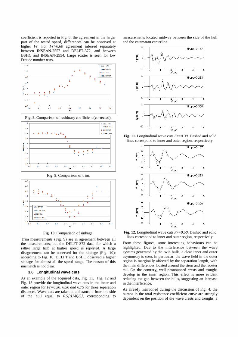
3.6 Longitudinal wave cuts As an example of the acquired data, Fig. 11, Fig. 12 and Fig. 13 provide the longitudinal wave cuts in the inner and outer region for Fr=0.30, 0.50 and 0.75 for three separation distances. Wave cuts are taken at a distance d from the side of the hull equal to 0.5[(H-b)/2], corresponding to
measurements located midway between the side of the hull and the catamaran centerline.
Fig. 11. Longitudinal wave cuts Fr=0.30. Dashed and solid
lines correspond to inner and outer region, respectively.
Fig. 12. Longitudinal wave cuts Fr=0.50. Dashed and solid
lines correspond to inner and outer region, respectively. From these figures, some interesting behaviours can be highlighted. Due to the interference between the wave systems generated by the twin hulls, a clear inner and outer asymmetry is seen. In particular, the wave field in the outer region is marginally affected by the separation length, with the main differences located around the stern and the rooster tail. On the contrary, well pronounced crests and troughs develop in the inner region. This effect is more evident reducing the gap between the hulls, suggesting an increase in the interference. As already mentioned during the discussion of Fig. 4, the humps in the total resistance coefficient curve are strongly dependent on the position of the wave crests and troughs, a
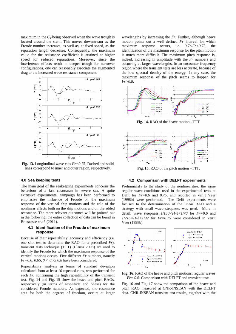
maximum in the CT being observed when the wave trough is located around the stern. This moves downstream as the Froude number increases, as well as, at fixed speed, as the separation length decreases. Consequently, the maximum value for the resistance coefficient is attained at higher speed for reduced separations. Moreover, since the interference effects result in deeper trough for narrower configurations, one can reasonably associate the augmented drag to the increased wave resistance component.
Fig. 13. Longitudinal wave cuts Fr=0.75. Dashed and solid
lines correspond to inner and outer region, respectively. 4.0 Sea keeping tests The main goal of the seakeeping experiments concerns the behaviour of a fast catamaran in severe sea. A quite extensive experimental campaign has been performed to emphasize the influence of Froude on the maximum response of the vertical ship motions and the role of the nonlinear effects both on the ship motions and on the added resistance. The more relevant outcomes will be pointed out in the following; the entire collection of data can be found in Bouscasse et al. (2011).
4.1 Identification of the Froude of maximum response
Because of their repeatability, accuracy and efficiency (i.e. one shot test to determine the RAO for a prescribed Fr), transient tests technique (TTT) (Clauss 2008) are used to identify the Froude for which the maximum response of the vertical motions occurs. Five different Fr numbers, namely Fr=0.6, 0.65, 0.7, 0.75 0.8 have been considered. Repeatability analysis in terms of standard deviation calculated from at least 10 repeated runs, was performed for each Fr, confirming the high repeatability of the transient test. Fig. 14 and Fig. 15 show the heave and pitch RAOs, respectively (in terms of amplitude and phase) for the considered Froude numbers. As expected, the resonance area for both the degrees of freedom, occurs at larger
wavelengths by increasing the Fr. Further, although heave motion points out a well defined Fr interval for which maximum response occurs, i.e. 0.7<Fr<0.75, the identification of the maximum response for the pitch motion is much more difficult. The maximum pitch response is, indeed, increasing in amplitude with the Fr numbers and occurring at larger wavelengths, in an encounter frequency region where the transient tests are less accurate, because of the low spectral density of the energy. In any case, the maximum response of the pitch seems to happen for Fr>0.8.
Fig. 14. RAO of the heave motion –TTT.
Fig. 15. RAO of the pitch motion –TTT.
4.2 Comparison with DELFT experiments
Preliminarily to the study of the nonlinearities, the same regular wave conditions used in the experimental tests at Delft for Fr=0.6 and 0.75, and reported in van’t Veer (1998b) were performed. The Delft experiments were focused to the determination of the linear RAO and a strategy with small wave steepness was used. More in detail, wave steepness 1/150<H/<1/70 for Fr=0.6 and 1/216<H/<1/92 for Fr=0.75 were considered in van’t Veer (1998b).
Fig. 16. RAO of the heave and pitch motions: regular waves
Fr= 0.6. Comparison with DELFT and transient tests. Fig. 16 and Fig. 17 show the comparison of the heave and pitch RAO measured at CNR-INSEAN with the DELFT data. CNR-INSEAN transient test results, together with the
corresponding error bar relative to the repeatability analysis, are also reported. The satisfactory agreement of the several results confirms the reliability of both the transient test technique and the experimental set-up used in the present experiments.
Fig. 17. RAO of the heave and pitch motions: regular waves
Fr= 0.75. Comparison with DELFT and transient tests.
Fig. 18. RAO of heave motion, Study of the non-linearities
induced by the wave steepness.
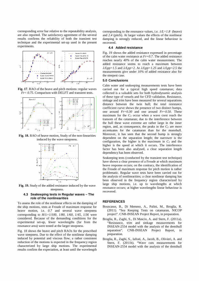
Fig. 19. Study of the added resistance induced by the wave
steepness. 4.3 Seakeeping tests in Regular waves – The
role of the nonlinearities To assess the role of the nonlinear effects on the damping of the ship motions, tests at Froude of maximum response for heave motion, i.e. 0.7 and several wave steepness corresponding to H/=1/100, 1/80, 1/60, 1/45, 1/36 were considered. Because of the demanding conditions for the experimental set-up, fewer wavelengths (far from the resonance area) were tested at the larger steepness. Fig. 18 shows the heave and pitch RAOs for the prescribed wave steepness. Due to the effect of the nonlinear damping induced by potential and viscous flow, a rather consistent reduction of the motions is expected in the frequency region characterized by large ship motions. The experimental results confirm the expectation, at least until the wavelength
corresponding to the resonance values, i.e. /L=1.8 (heave) and 2.4 (pitch). At larger values the effects of the nonlinear damping is strongly reduced, and the linear behaviour is recovered.
4.4 Added resistance Fig. 19 shows the added resistance expressed in percentage of the calm water resistance at Fr=0.7. The added resistance reaches nearly 40% of the calm water measurement. The added resistance seems to reach a maximum between /Lpp=1.5 and /Lpp=2. At /Lpp=1.25 and /Lpp=2.5 the measurements give under 10% of added resistance also for the steepest case. 5.0 Conclusions Calm water and seakeeping measurements tests have been carried out for a typical high speed catamaran; data collected is a valuable sets for both hydrodynamic analysis of these type of vessels and for CFD validation. Resistance, sinkage and trim have been measured for several separations distance between the twin hull; the total resistance coefficient curve shows the presence of two distinct humps, one around Fr=0.30 and one around Fr=0.50. These maximum for the CT occur when a wave crest reach the transom of the catamaran; due to the interference between the hull these wave extreme are rather large in the inner region, and, as consequence, the peaks in the CT are more accentuates for the catamaran than for the monohull. Moreover, it has seen that the second hump is strongly dependent on the separation length; the narrower is the configuration, the higher is the maximum in CT and the higher is the speed at which it occurs. The interference factor has been also analysed, a clear separation length dependency has been observed. Seakeeping tests (conducted by the transient test technique) have shown a clear presence of a Froude at which maximum heave response occurs; on the contrary, the identification of the Froude of maximum response for pitch motion is rather problematic. Regular wave tests have been carried out for the analysis of nonlinearities; a clear nonlinear damping has been observed in the frequency region characterized by large ship motions, i.e. up to wavelengths at which resonance occurs; at higher wavelengths linear behaviour is recovered. REFERENCES Bouscasse, B., Di Memmo, A., Palini, M., Broglia, R.
(2011). “Sea Keeping Tests on catamaran, NICOP project”. CNR-INSEAN Project Report, in preparation.
Broglia, R., Zaghi, S., Di Mascio, A. and Stern, F. (2011a). “Resistance, trim and sinkage measurements for INSEAN-2554 model with the analysis of the demihull separation”. CNR-INSEAN Project Report, in preparation.
Broglia, R., Zaghi, S., Iafrati, A., Jacob, B., Olivieri, A. and Stern, F. (2011b). “Wave cuts measurements for INSEAN-2554 model with the analysis of the demihull
separation”. CNR-INSEAN Project Report, in preparation.
Broglia, R., Zaghi, S., and Di Mascio, A. (2011c). “Numerical Simulation of Interference Effects for a High-Speed Catamaran”. Submitted to J. of Marine Science and Technology.
Castiglione, T., Stern, F., Bova, S. and Kandasamy, M. (2010). “Numerical Investigation of the Seakeeping Behavior of a Catamaran Advancing in Regular Head Waves”. Submitted to Ocean Engineering.
Clauss, G. (2008) “The Taming of the Shrew: Tailoring Freak Wave Sequences for Seakeeping Tests.” Journal of Ship Research Vol. 52, No. 3.
Coleman, H.W. and Steele, W.G. (2009), “Experimentation, validation, and uncertainty analysis for engineers”, John Wiley & Sons.
Doctors, L. (2003). “The Influence of Viscosity on the Wavemaking of a Model Catamaran”. 8th International Workshop on Water Waves and Floating Bodies, Le Croisic, France, pp. 121.
Insel, M., Molland, A., (1992). “Investigation into the resistance components of high speed displacement catamarans”. Transactions of Royal Institute of Naval Architects , 1-20.
Milanov, E., Zlatev, Z., Chotukova, V. and Stern F. (2010), “Numerical and Experimental Prediction of the Inherent Course Stability of High Speed Catamaran in Deep and Shallow Water”, 28th Symposium on Naval Hydrodynamics Pasadena, California, 12-17 September.
Milanov, E. and Georgiev, S. (2010), “Model Tests of Waterjet Propelled Delft 372 Catamaran”, BSHC Technical Report KP092006/01.
Millward, A. (1992). “The effect of hull separation and restricted water depth on catamaran resistance”. Transactions of Royal Institute of Naval Architects 134, 341-349.
Molland, A., Wellicome, J., Couser, P. (1996). “Resistance experiments on a systematic series of high speed catamaran forms: Variation of length-displacement ratio and breadth-draught ratio”. Transactions of the Royal Institution of Naval Architects 138, 59-71.
Molland, A., Wilson, P., Taunton, D., Chandraprabha, S., Ghani, P. (2004). “Resistance and wash measurements on a series of high speed displacement monohull and catamaran forms in shallow water”. International Journal of Maritime Engineering 146, 19-38.
Miozzi, M. (2011), “Towing and self-propulsion tests of waterjet propeller DELFT-372 catamaran”, CNR-INSEAN Technical Report, in preparation.
Souto-Iglesias, A., R. Zamora-Rodríguez, R., Fernández-Gutiérrez, D. And L. Pérez-Rojas, L. (2007), “Analysis of the wave system of a catamaran for CFD validation”, Exp. Fluids, Vol. 42, pag. 321–333.
Stern, F., Carrica, P., Kandasamy, M., Gorski, J., O’Dea, J., Hughes, M., Miller, R., Hendrix, D., Kring, D., Milewski, W., Hoffman, R., , and Cary, C. (2006), “Computational Hydrodynamic Tools for High-Speed Transports”, In Transaction SNAME, volume 114.
Van't Veer, R. (1998a), “Experimental results of motions, hydrodynamic coefficients and wave loads on the 372 Catamaran model”, TU Delft Report, N.1129.
Van't Veer, R. (1998b), “Experimental results of motions and structural loads on the 372 catamaran model in head and oblique waves”, TU Delft Report, N.1130.
Zaghi, S., Broglia, R., and Di Mascio, A. (2011). “Analysis of the Interference Effects for High-Speed Catamarans by Model Tests and Numerical Simulations”, submitted to Ocean Engineering.
Zlatev, Z., Milanov, E., Chotukova, V., Sakamoto, N. and Stern, F. (2009), “Combined model-scale EFD-CFD investigation of the maneuvering characteristics of a high speed catamaran”, In Proc. of the 10th Int. Conf. on Fast and Sea Transportation, FAST 2009, Athens, Greece.
ACKNOWLEDGEMENTS The work has been done in the framework of the NICOP project “Complementary EFD and CFD Analysis of Calm Water Hydrodynamics and Large Amplitude Motion for High-Speed Catamarans” financially supported by the U.S. Office of Naval research, through Dr. L. Patrick Purtell (Grant N00014-08-1-1037).