cansat program - stensat group llc · introduction to cansat ... it is arduino compatible
TRANSCRIPT

CanSat Program
StenSat Group LLC

Legal Stuff● Stensat Group LLC assumes no responsibility and/or liability for the
use of the kit and documentation.
● There is a 90 day warranty for the Lander kit against component defects. Damage caused by the user or owner is not covered.
● Warranty does not cover such things as over tightening nuts on standoffs to the point of breaking off the standoff threads, breaking wires off the motors, causing shorts to damage components, powering the motor driver backwards, plugging the power input into an AC outlet, applying more than 12 volts to the power input, dropping the kit, kicking the kit, throwing the kit in fits of rage, unforseen damage caused by the user/owner or any other method of destruction.
● If you do cause damage, we can sell you replacement parts or you can get most replacement parts from online hardware distributors.
● If you need to contact us, go to www.stensat.org and click on contact us.

3
Introduction to CanSat● CanSat is a simulation of a real satellite.
● It performs a mission and collects data.
● Typical CanSat missions can be atmospheric measurements, video capture, imaging, communications or navigation.
● Missions can be simple or complex.
● The only requirement is that the mission must fit in a twelve ounce soda can.
● This program will introduce you to how CanSats are built.
● It includes most components found in a satellite.
4
The CanSat Mission● What is the mission
● Launch a CanSat in a rocket to some altitude and deploy Cansat from the rocket.
● CanSat is to float back to earth on a parachute.
● CanSat is to measure the atmospheric pressure during flight.
● CanSat is to support additional sensors during flight.
● CanSat is to transmit the sensor data to a ground station periodically.

5
CONOPS● CONOPS = Concept of Operations
● Description of the mission operations from beginning to end.
● Covers all operations
– Rocket preparations
– Cansat preparations
– Ground Station preparations
– Cansat integration into rocket
– Rocket launch
– Deployment from rocket
– Data collection
– Recovery
– Personnel assignments
– Contingency plans

6
Mission Operation● CanSat is launched on a high
power rocket to some altitude.
● Rocket needs to be at least 3 inches in diameter.
● When the rocket reaches peak altitude also known as apogee, the rocket deploys the rocket parachute.
● The upper section of the rocket will point down causing the nose cone and cansat to fall out.
● The cansat floats back to eartch under parachute transmitting its sensor data called telemetry.

7
CanSat Kit Mission● Launch a CanSat in a rocket to some altitude and be
deployed.
● CanSat floats back to earth on a parachute.
● CanSat measures atmospheric pressure and other sensor data during flight.
● CanSat transmits data to a ground station every couple seconds.
● CanSat lands and completes mission.

8
CanSat Components● CanSat is composed of several
components● 9V battery is the power system.
● Microcontroller is the data handling unit. It interfaces to everything.
● Transmitter is the communications system used to send data to the ground station.
● The sensor module is the payload.
● The block diagram shows how the various systems connect.
9VoltBattery
Microcontroller
PressureSensor
Sensor 2
Transmitter
ADC
VREG
5V PowerDistribution
PowerSubsystem
Data HandlingUnit
Sensor Payload
Communications System
Sensor 3

9
Data Handling Unit● Data Handling Unit (DHU)
includes the microcontroller with program and data memory.
● It is Arduino compatible● Atmega168 at 8 MHz.
● 6 analog inputs
● 2 Servo/PWM ports
● I2C port
● Communications port
PowerConnector
Power Switch
USB Port
PWMPort
CommunicationPort
AnalogPort
Processor

10
TransmitJP1
Pin Function 1 5 Volts 2 Ground 3 Transmit 4 Receive
SensorsJP2
Pin Top Bottom 1 ADC0 ADC3 2 ADC1 ADC6 3 ADC2 ADC7 4 Ground Ground 5 5 Volts 5 Volts
I2C InterfaceJP19
Pin Function 1 SCL 2 SDA 3 Ground 4 5 Volts
DHU Pin Definitions
PWM/ServoPin Top Bottom 3 Ground Ground 2 5 Volts 5 Volts 1 P9 P10

11
Power System● The 9 volt battery is the power system.
● It has a capacity of 500 milliamp hours.
● CanSat consumes about 100 milliamps.
● The battery can provide about 5 hours of operation.
● The electronics uses 5 volts.
● A voltage regulator on the DHU converts the battery voltage to a steady 5 volts.

12
Communications System● The communications system is a radio transmitter.
● It transmits data in a packet format or protocol called AX.25
● AX.25 is a standard digital communications format used in amateur radio.

13
CanSat Structure● Structure is designed to be simple
and rugged.● It is made of aluminum.
● Holes are drilled to support mounting DHU, sensor payload, transmitter, and battery.
● It has an attachment point for the parachute.

14
Attitude Control● Attitude control system is a
parachute● Parachute maintains pointing
direction of CanSat.
● Transmitter antenna orientation toward the ground.
● Cansat can rotate around vertical axis.

15
Sensor Payload● There is one sensor and two expansion ports on the
sensor module.
● Pressure sensor measures the atmospheric pressure and generates a voltage in proportion to the atmospheric pressure.
● Two expansion sensor ports allows other analog sensors to be added.
Pressure Sensor Connection
to DHU
Sensor 2 Port Sensor 3 Port

16
Pressure Sensor Operation● Pressure sensor operation
● Generates voltage in proportion to atmospheric pressure
● Linear relationship
● Voltage increases with increasing pressure
● Plot at right shows the relationship
● Structure of pressure sensor
● Uses piezoresistive material that changes resistance by the amount of deflection
● Mounted on silicon die
● Below piezoresistive material is a chamber under vacuum
● At one atmosphere, the piezoresistive material is at maximum deflection.
● Deflection reduces as air pressure descreases
● On chip electronics converts resistance to voltage
17
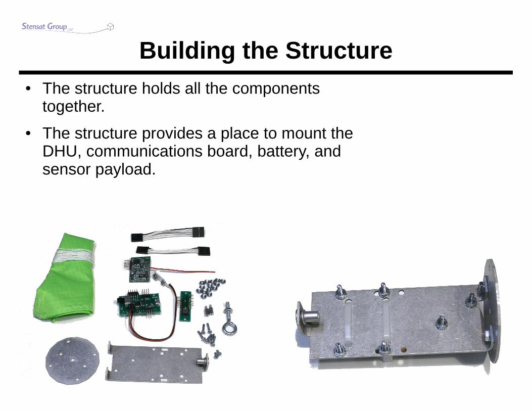
Building the Structure● The structure holds all the components
together.
● The structure provides a place to mount the DHU, communications board, battery, and sensor payload.

18
Parts List● Electronics
● Data Handling Unit
● Sensor Module
● Transmitter Module
● USB cable
● Structure● Aluminum disc
● Aluminum structure
● 2, cable ties
● Hardware● 6, 4-40 1/2 inch screws
● 2, 4-40 1/4 inch screws
● 18, 4-40 nuts
● 2, 4-40 5/8 inch standoffs
● 10-24 machine screw eyelet

19
CanSat Assembly● Attach the main structure to the disc as shown and secure
with two 4-4 1/4 inch screws and two nuts.
● Nuts are secured on the inside of the structure as shown below.
20
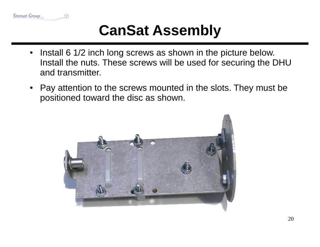
CanSat Assembly● Install 6 1/2 inch long screws as shown in the picture below.
Install the nuts. These screws will be used for securing the DHU and transmitter.
● Pay attention to the screws mounted in the slots. They must be positioned toward the disc as shown.

21
CanSat Assembly● Flip the structure over and secure the battery with two cable
ties.
● Make sure square part is kept below the level of the battery so it will fit in the can later.
● Trim the excess cable tie with a wire cutter or scissors.

22
StandoffsSensor Board
CanSat Assembly● Mount the circuit boards as
shown in the picture.● Pay attention to the
orientation
● Secure the transmitter with two nuts.
● Secure the DHU with two nuts and two standoffs as shown in the picture.
● Mount the sensor board on top of the standoffs as shown and secure with nuts.
– Do not over tighten the nuts on the sensor board. The standoffs are made of aluminum and will break if tightened too much.

23
Connecting the Sensor Board● Look at the sensor
board 5 pin connector. There is a white '1' on the board indicating pin 1. On the DHU, there is a 5-pin dual row connector in the opposite direction.
● Connect the 5-pin cable and orient it so the black wire is next to the number '1' on both ends.
● Connect to the top row pins on the DHU.
24
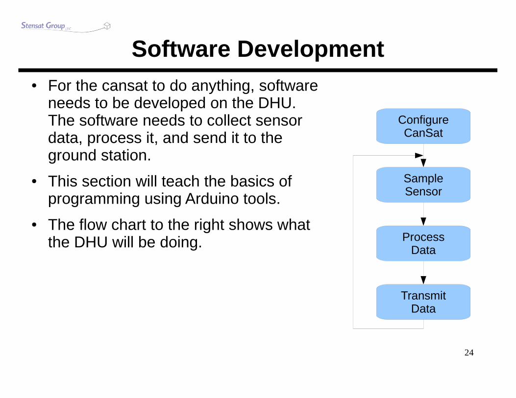
Software Development● For the cansat to do anything, software
needs to be developed on the DHU. The software needs to collect sensor data, process it, and send it to the ground station.
● This section will teach the basics of programming using Arduino tools.
● The flow chart to the right shows what the DHU will be doing.
ConfigureCanSat
SampleSensor
ProcessData
TransmitData
25
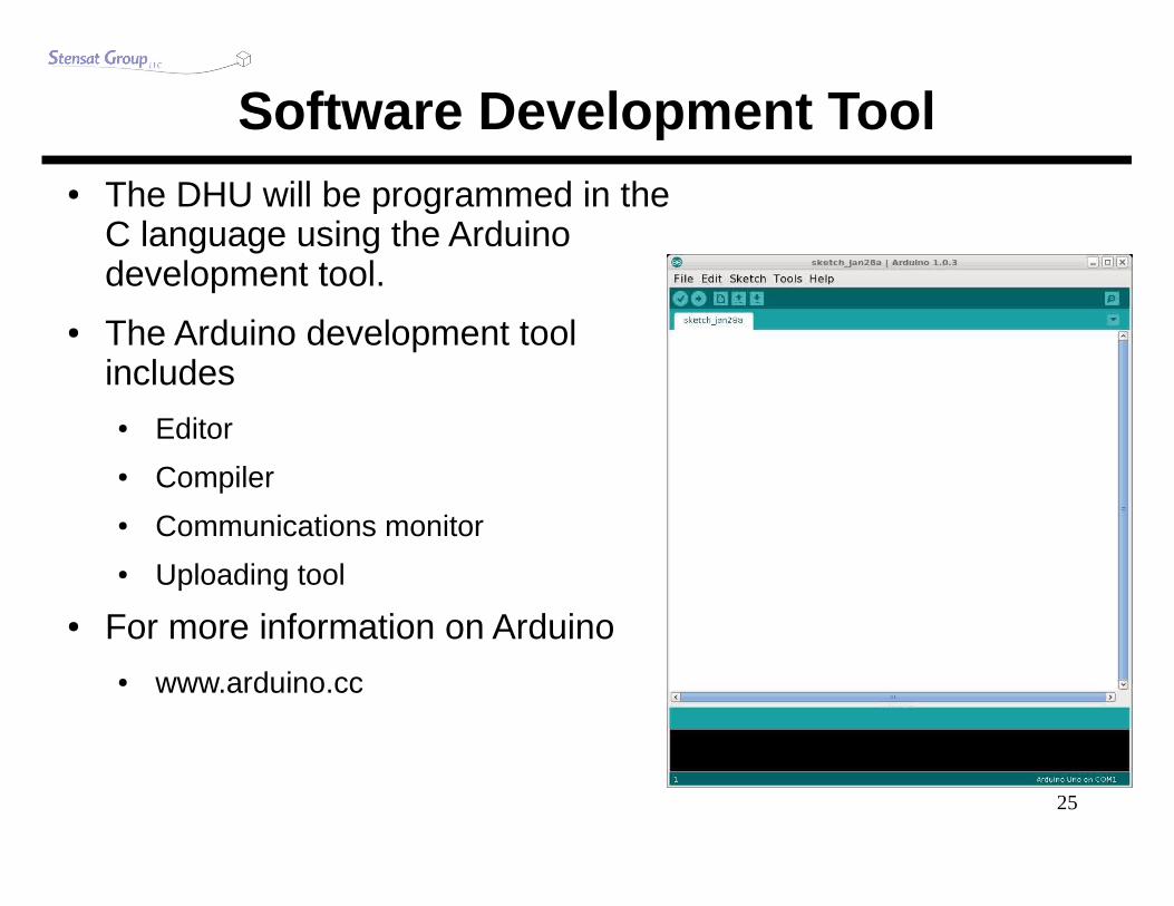
Software Development Tool● The DHU will be programmed in the
C language using the Arduino development tool.
● The Arduino development tool includes
● Editor
● Compiler
● Communications monitor
● Uploading tool
● For more information on Arduino● www.arduino.cc

26
Setting up the Software● Drag the arduino folder to any location on the computer.
Desktop location is fine.
● Open the folder on the computer and double click on the arduino program icon.
● When the program starts do the following:● Click on “Tools” menu
● Select “Board” menu
● Select “CanSat” or “Arduino Pro or Pro Mini (3.3V 8MHz) with ATMega168”
● Click on “Tools” menu again
● Select “Serial Port” (only when DHU is connected)
● “Click on the appropriate COM port.
– The port will be the highest number.

27
COM Device Driver● Under Windows, some times the computer doesn't find the
device driver. Go into the device manager and select the FTDI serial device and select update driver.
● Don't let Windows attempt to find it automatically, specify the location. It is located in the Arduino folder under drivers.
28
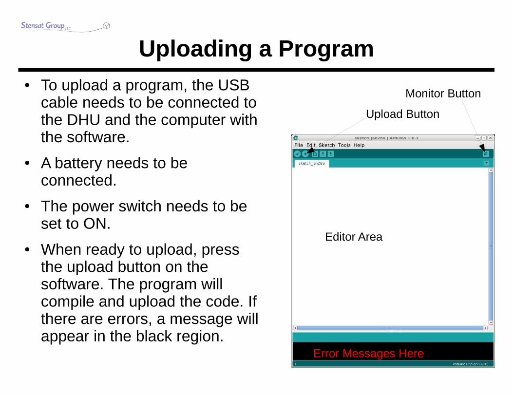
Uploading a Program● To upload a program, the USB
cable needs to be connected to the DHU and the computer with the software.
● A battery needs to be connected.
● The power switch needs to be set to ON.
● When ready to upload, press the upload button on the software. The program will compile and upload the code. If there are errors, a message will appear in the black region.
Upload Button
Editor Area
Error Messages Here
Monitor Button

29
First Program● In the editor section, enter
the code to the right.
● When complete, click on the upload button.
● When upload completed, click on the monitor button.
● Change the baud rate in the lower right corner to 38400.
● A message should now appear.
void setup(){
Serial.begin(38400);}
void loop(){
Serial.println(“Hello world”);}

30
Program Structure● Each statement requires a
semi-colon at the end.
● The program is broken into two functions.
● setup function is executed at power up or reset once and is used to initialize parts of the cansat such as the communications port shown.
● loop function is executed over and over and is the main part of the program.
● Functions are grouped with { and }
void setup(){
Serial.begin(38400);}
void loop(){
Serial.println(“Hello world”);}

31
What Does It All Mean● Serial.begin(38400);
● This command sets up the communications port to operate at 38,400 bits per second. This is used to print messages to the Monitor window.
● It will also be used to communicate with the transmitter module.
● This command initializes the DHU serial port for communications operations.
● Serial.println(“Hello world”);● This command sends the message in quotes and moves the
monitor cursor down one line by sending newline and carriage return codes after what is sent in quotes.

32
Blinking the LED● The DHU has an LED (light emitting diode). It is connected
to digital port 8.
● Arduino provides a command to control digital ports.
● The port has to be initialized first to operate as an output.
● Once initialized, it can be controlled by setting the signal high or low (On or off).
● When set high, the port is set to 5 volts.
● When set to low, the port is 0 volts.

33
Blinking LED Program● Modify the first program to
blink the LED as shown to the right.
● Upload the program and observe how the LED behaves.
● Chances are it looks like it is a steady glow. This is because the LED is blinking faster than can be observed.
void setup(){
Serial.begin(38400);pinMode(8,OUTPUT);
}
void loop(){
Serial.println(“Hello world”);digitalWrite(8,HIGH);digitalWrite(8,LOW);
}

34
Slowing It Down● There is a command that can
be used to slow the program down.
● delay(ms);● This command will stop the
program for the specified number of milliseconds. There is 1000 milliseconds per 1 second.
● Modify the program to include the delay() command.
● Upload and see how the program behaves.
● Next, change the length of the delay and try again.
void setup(){
Serial.begin(38400);pinMode(8,OUTPUT);
}
void loop(){
Serial.println(“Hello world”);digitalWrite(8,HIGH);delay(1000);digitalWrite(8,LOW);delay(1000);
}

35
Sampling the Sensor● Next step is to sample the pressure sensor.
● Recall that the pressure sensor generates a voltage in proportion to the pressure measured.
● The voltage ranges from 0 to 5 volts.
● The DHU has a device built in called the analog-to-digital converter (ADC).
● It measures the voltage and generates a value in proportion to the voltage.
● The ADC has 10 bits meaning it can generate a number from 0 to 1023.
– 0 is for 0 volts
– 1023 is for 5 volts
– There is a linear relationship. 2.5 volts = 511.
– The voltage can be calculated using the equation● voltage = ADC/1023 * 5

36
Sampling the Sensor● The command to sample the
sensor is● value = analogRead(channel)
– channel is the analog port to sample.
– The pressure sensor is on analog port 0.
– value is a variable and needs to be declared.
● variables are memory storage.
● Enter the program to the right and upload it.
● Open the communications monitor and observe the results.
void setup(){
Serial.begin(38400);}
void loop(){
int value;value = analogRead(0);Serial.println(value,DEC);delay(1000);
}

37
Sampling Sensors● Variables are memory storage
locations. They need to be created.
● int value;● Creates a storage location for an integer
number.
– An integer number is a whole number, no fractions.
● a variable can be any name as long as it is not a command name.
● You will notice that Serial.println() is printing out the value of the variable.
● DEC tells the compiler to print in decimal.
● The result is a number that indicates the voltage the sensor is generating but the value is not in volts.
void setup(){
Serial.begin(38400);}
void loop(){
int value;value = analogRead(0);Serial.println(value,DEC);delay(1000);
}

38
What Next ● The number generated may not
mean much.
● It can be converted to a more understandable number, the actual voltage.
● To do that requires data processing
● Convert the ADC value to a voltage
● voltage = ADC/1023 * 5.0– The voltage will have a fraction to it so
a new type of variable is required.● float.
– float lets you have fractional numbers.
void setup(){
Serial.begin(38400);}
void loop(){
int value;float voltage;value = analogRead(0);voltage = value / 1023.0 * 5.0;Serial.println(voltage,2);delay(1000);
}

39
Voltage Measurements● Serial.println(voltage,2);
● This now prints a floating fractional number.
● The '2' specifies how many digits after the decimal point to display.
– Change it to another value and see what happens.
● The voltage conversion equation is the same for all sensor sampling.
void setup(){
Serial.begin(38400);}
void loop(){
int value;float voltage;value = analogRead(0);voltage = value / 1023.0 * 5.0;Serial.println(voltage,2);delay(1000);
}

40
Calculating Air Pressure● Voltage equation for pressure sensor
● V = 5.0 * (0.007826 * P – 0.07739)
● Solving for pressure value● V = 0.03934*P – 0.38695
● 0.03934*P = V + 0.38695
● P = 25.419*P + 9.836
void setup(){
Serial.begin(38400);}
void loop(){
int value;float voltage,p;value = analogRead(0);voltage = value / 1023.0 * 5.0;p = 25.419 * voltage + 9.836;Serial.println(p,2);delay(1000);
}

41
Testing the Pressure Sensor● A straw can be used to test
the pressure sensor.
● Using the last program that displays the pressure, place one end of the straw over the hole of the pressure sensor. Make sure the straw is straight up on top.
● Try sucking the air through the straw to drop the pressure.
● Observe the pressure drop being displayed.
● Don't pass out.
Pressure Porton Metal Sideof Sensor

42
Radio Communications● The transmitter module has its own processor that
interprets commands from the DHU and generates the AX.25 packets automatically.
● The data is sent at 1200 bits/second using tones● 1200 Hz and 2400 Hz are the two tones representing 1
and 0.
● Below is the AX.25 packet structure.
Bytes:
The AX.25 Frame
1
ProtocolID
1-256
Information Field
2
Frame Checksum
1
FlagControl Field(UI)
Digipeater Addresses
(0-8)
Source Address
Destination Address
Flag
10-56771
AX.25 UI-Frame Format

43
Wiring the Transmitter● Connect the
transmitter with the 4-wire cable.
● The 4-pin connector goes to the DHU. Black wire is next to the '1'.
● The 5-pin connector is oriented with the black wire toward the edge of the board, opposite of the nut.
● The cable can be looped as shown in the picture.

44
Ground Station● The ground station is where data is collected from the
CanSat● It consists of a computer, radio receiver, and antenna.
● The antenna is either a whip antenna or yagi.● A yagi antenna requires pointing to capture the signal.
● The radio receiver detects and demodulates the radio signal. The demodulated signal is an audio signal.
● The audio signal is fed into the computer microphone port for decoding.
● The computer receiver software will decode the audio tones into data.

45
Ground Station Configuration● The ground station consists of a Bearcat radio scanner,
antenna, audio cable,and a computer with a microphone port.
● The audio port of the scanner is connected to the microphone port of the computer.
● If operating at 433.92 MHz, the Bearcat scanner whip antenna is sufficient.
● If operating at 916 MHz, the Bearcat scanner antenna is replaced with a yagi antenna. Connect the coax cables between the scanner and antenna.

46
Ground Station Software● The software used is a free program called “AGW Packet Engine”
● Copy the AGW software folder to the computer.
● Double click “AGW Packet Engine”
● After the startup image goes away, right click on the menu bar that looks like a little radio tower.
● Select “Properties”
● Click on the “New Port” button
● Click “OK” on the next window prompt.
● A large window should appear. Look for the box that says “TNC Type”
● Select “Sound Card”
● Click OK.
● Click on the radio tower icon and select “quit”
● Restart the program.

47
Running the Ground Station● In the AGW directory, start the AGWMonitor Program.
● You should be ready to receive data from the CanSat.● You may have to adjust the microphone level to decode properly.
● Also, turn off any microphone filters or audio processing add-ons. They may keep packets from decoding.
● There are some computers that just don't work because of how the microphone port is designed. Try other computers to make sure.

48
Commanding the Transmitter● The transmitter uses a single
character command.
● Start a new program and put this in the loop() function.
● Serial.println(“SHello world”);
● Make sure you add a delay afterwards of 2 seconds.
● The transmitter will send the message.
● If 'S' is not included, the transmitter will ignore the message.
void setup(){
Serial.begin(38400);}
void loop(){
Serial.println(“SHello world”);delay(2000);
}

49
Transmitter Identification● Part of the AX.25 protocol is the call sign which is an
identifier of the transmitter.
● There is a command to set the call sign.● Serial.println(“CAB4CDE”);
– Up to 6 letters and number can used in the call sign.
– The command is 'C'.
– This should be put in the setup() function since it only needs to be set once.

50
Example Transmitter Usage● Check out the
example code on how to set up the transmitter and use it in the loop.
void setup(){
Serial.begin(38400);delay(500);Serial.println(“CMYCALL”);
}
void loop(){
Serial.println(“SThis is a test.”);delay(2000);
}

51
Putting it All Together● Now, take all that has been
learned, and write program to sample the pressure sensor and send the data to the ground station.
● Follow the flow chart.
● You can take the program from page 36 and modify it to transmit over the transmitter.
ConfigureCanSat
SampleSensor
ProcessData
TransmitData
Wait 2Seconds

52
Final CanSat Preparations● Time to put it in a can.
● Get your favorite soda can.
● Using a cheap (cheap works best) can opener, open the top of the soda can.
● A cheap can opener cuts the top off leaving no sharp edges. The expensive fancy ones do not work.
● Drill a 1/4 inch hole in the bottom.
● Drill another hole in the side.
● Turn on the cansat.
● Insert the cansat structure into the soda can.
● Feed the eyebolt through the bottom hole and screw into the structure.
● Secure the parachute to the eyebolt.
● Ready for launch.

53
Some Tips● The CanSat may be tight going into the top of the soda can. You can
squeeze the top of the soda can to deform the opening a bit.
● It is suggested that the battery be wrapped in electrical tape to stay in place. The deployment from the rocket may be a bit violent sometimes.
● Use a 3 inch diameter rocket with a payload section long enough to fit the cansat and parachute.
● Add some wadding to the bottom of the payload section to protect the cansat from the payload section eye-bolt if present.
● Insert cansat parachute first. This way the cansat slides out and the parachute will less likely be tangled with the cansat.
● Let the rocket nose cone be loose on the payload section of the rocket. This will let everything slide out. The person checking rockets at a launch may want the nose cone more secured but it has to be very loose. This configuration has been tested and used many times.
● Holes can be drilled into the rocket payload section so that the air pressure inside will be equal with the outside air pressure reducing the chance of the nose cone being pushed out during flight.

54
Adding Your Own Sensors● Adding sensors is
simple.
● There are two expansion ports on the sensor module.
● Each port has three pins.
– 1 = signal
– 2 = 5V
– 3 = Ground/0V
● Use the sensor expansion cable to connect another sensor.
● Make sure the sensor does not generate more than 5 volts. It can damage the DHU.
Pins 3 2 1Ground 5V AN1
Pins 3 2 1Ground 5V AN2

55
Final Program Listing● In case you can't
figure out how to get the final program working, here is one example.
void setup(){
Serial.begin(38400);pinMode(8,OUTPUT);delay(500);Serial.println(“CMYCALL”);
}
void loop(){
int a;float volt,pressure;a = analogRead(0);volt = a / 1023.0 * 5.0;pressure = 24.419 * volt + 9.836;Serial.print(“SPressure “);Serial.println(pressure,2);delay(2000);
}

56
Program Sampling 3 Analog Ports● This program adds the
other two sensor module ports. Only the ADC value is printed.
● Notice that each value is separated by a space and a separate Serial.print() statement is needed.
void setup(){
Serial.begin(38400);pinMode(8,OUTPUT);delay(500);Serial.println(“CMYCALL”);
}
void loop(){
int a,b,c;float volt,pressure;a = analogRead(0);b = analogRead(1);c = analogRead(2);volt = a / 1023.0 * 5.0;pressure = 24.419 * volt + 9.836;Serial.print(“SPressure “);Serial.print(pressure,2);Serial.print(“ “);Serial.print(b,DEC);Serial.print(“ “);Serial.println(c,DEC);delay(2000);
}

57
Temperature Sensor Example● There are temperature sensor
devices such as the TMP37 made by Analog Devices. It generates a voltage in relation to temperature.
● V = 0.01 * C + 0.5
● V is the voltage and C is the temperature in Celcius.
● Solve for C and the equation is now
● C = 100.0 * V – 50.0
● Sample code is to the right.
void setup(){
Serial.begin(38400);}
void loop(){
int a;float volt,c;a = analogRead(1);volt = a / 1023.0 * 5.0;c = 100.0 * volt – 50.0;Serial.println(c,2);delay(1000);
}

58
Solar Cell Example● It is easy to connect a solar cell to one of the extra analog
ports on the sensor module.
● Two connections are needed● Pin 1 (signal) is connected to the positive side of the solar panel.
● Pin 3 (ground) is connected to the negative side of the solar panel.
● Make sure the maximum voltage of the solar panel does not exceed 5 volts. This is also called the open circuit voltage. Damage to the DHU can occur if the solar panel is greater than 5 volts.
● Use the voltage conversion equation to get the voltage of the solar panel.