carbon absorber retrofit equipment (care) final … library/research/coal...de-fe0007528 final...
TRANSCRIPT
DE-FE0007528 FINAL SCIENTIFIC/TECHNICAL REPORT Page | 1
Carbon Absorber Retrofit Equipment (CARE)
Final Scientific/Technical Report
Reporting Period Start Date: January 2, 2012 Reporting Period End Date: December 31, 2015
(719) 247-8513
Submission Date: December 23, 2015
Contract No. DE-FE0007528
Neumann Systems Group 890 Elkton Drive, Suite 101
Colorado Springs, CO 80907
DE-FE0007528 FINAL SCIENTIFIC/TECHNICAL REPORT Page | 2
Disclaimer: This report was prepared as an account of work sponsored by an agency of the United States Government. Neither the United States Government nor any agency thereof, nor any of their employees, makes any warranty, express or implied, or assumes any legal liability or responsibility for the accuracy, completeness, or usefulness of any information, apparatus, product, or process disclosed, or represents that its use would not infringe privately owned rights. Reference herein to any specific commercial product, process, or service by trade name, trademark, manufacturer, or otherwise does not necessarily constitute or imply its endorsement, recommendation, or favoring by the United States Government or any agency thereof. The views and opinions of authors expressed herein do not necessarily state or reflect those of the United States Government or any agency thereof. I. ABSTRACT:
During Project DE-FE0007528, CARE (Carbon Absorber Retrofit Equipment), Neumann Systems Group (NSG) designed, installed and tested a 0.5MW NeuStream® carbon dioxide (CO2) capture system using the patented NeuStream® absorber equipment and concentrated (6 molal) piperazine (PZ) as the solvent at Colorado Springs Utilities’ (CSU’s) Martin Drake pulverized coal (PC) power plant. The 36 month project included design, build and test phases. The 0.5MW NeuStream® CO2 capture system was successfully tested on flue gas from both coal and natural gas combustion sources and was shown to meet project objectives. Ninety percent CO2 removal was achieved with greater than 95% CO2 product purity. The absorbers tested support a 90% reduction in absorber volume compared to packed towers and with an absorber parasitic power of less than 1% when configured for operation with a 550MW coal plant. The preliminary techno-economic analysis (TEA) performed by the Energy and Environmental Research Center (EERC) predicted an over-the-fence cost of $25.73/tonne of CO2 captured from a sub-critical PC plant.
II. TABLE OF CONTENTS:
I. ABSTRACT: ......................................................................................................................................... 2
II. TABLE OF CONTENTS: ..................................................................................................................... 2
III. EXECUTIVE SUMMARY: ................................................................................................................. 3
IV. EXPERIMENTAL METHODS ............................................................................................................ 4
V. RESULTS AND DISCUSSIONS ......................................................................................................... 5
A. DESIGN PHASE .............................................................................................................................. 5
B. CONSTRUCTION PHASE .............................................................................................................. 8
C. TESTING PHASE .......................................................................................................................... 10
VI. CONCLUSIONS: ............................................................................................................................... 14
VII. REFERENCES: .................................................................................................................................. 15
VIII. LIST OF ACRONYMS AND ABBREVIATIONS ............................................................................ 16
DE-FE0007528 FINAL SCIENTIFIC/TECHNICAL REPORT Page | 3
III. EXECUTIVE SUMMARY:
During project CARE (Carbon Absorber Retrofit Equipment), Neumann Systems Group (NSG) designed, installed and tested a 0.5MW NeuStream® carbon dioxide (CO2) capture system using concentrated (6 molal) piperazine (PZ) as the solvent at Colorado Springs Utilities’ (CSU’s) Martin Drake pulverized coal (PC) power plant. Prior to and during the CARE program, NSG piloted its NeuStream® system for CO2 capture at the 70kW and 100kW scales using both PC and natural gas (NG) burning CO2 sources.
The CARE program summarized herein was a 36 month project consisting of separate and distinct design, build and test phases. During the design phase, the CARE system was designed to meet program objectives including 90% CO2 capture and 95% CO2 product purity. Design verification testing (DVT) was performed to facilitate nozzle selection to minimize parasitic power associated with the absorber recirculation pumps. During the build phase, system components were procured and fabricated and the system was constructed at CSU’s Martin Drake PC power plant and integrated with Unit 7’s flue gas.
During the test phase, shakeout testing was completed and parametric testing started when an unrelated turbine fire at the Drake plant resulted in a long-term outage. As such, the CARE system was relocated to NSG’s facility and integrated with flue gas supplied by a natural gas boiler, and captured CO2 was recycled to the absorber inlet to simulate coal flue gas (~13% CO2). Due to space constraints at the NSG location, only 3 of the 4 absorber units were relocated, such that the expected capture efficiency at design gas flow rates would decrease from 90% to ~80% and the gas flow would need to be de-rated in order to realize 90% CO2 capture. The testing of the 0.5MW CARE system at NSG culminated in a one week continuous 24x7 extended run. During this extended run, CO2 capture efficiency and specific surface area were characterized as a function of gas velocity.
Capture efficiencies were demonstrated to match expected values during testing using both coal and natural gas as the flue gas source. CO2 capture efficiency was determined to be 90% at the Drake site (coal flue gas source) with 4 absorber units in operation during a parametric test at 0.44MW equivalent gas flow. CO2 capture efficiency was determined to be 80% at the NSG location (natural gas flue gas source) with 3 absorber units in operation at the design 0.5MW gas flow. Regenerated CO2 purity was measured to be 98.6%, exceeding the 95% project goal.
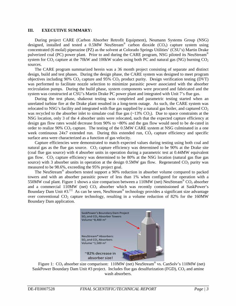
The NeuStream® absorbers tested support a 90% reduction in absorber volume compared to packed towers and with an absorber parasitic power of less than 1% when configured for operation with a 550MW coal plant. Figure 1 shows a size comparison between a 110MW (net) NeuStream® CO2 absorber and a commercial 110MW (net) CO2 absorber which was recently commissioned at SaskPower’s Boundary Dam Unit #3.[1] As can be seen, NeuStream® technology provides a significant size advantage over conventional CO2 capture technology, resulting in a volume reduction of 82% for the 160MW Boundary Dam application.
Figure 1: CO2 absorber size comparison: 110MW (net) NeuStream® vs. CanSolv’s 110MW (net)
SaskPower Boundary Dam Unit #3 project. Includes flue gas desulfurization (FGD), CO2 and amine wash absorbers.
NeuStream® Absorbers:SO2 and CO2 AbsorbersVolume ~1,500 m3
SaskPower’s Boundary Dam ProjectSO2 and CO2 Absorber TowersVolume ~8,400 m3
~82% decrease in absorber size!
DE-FE0007528 FINAL SCIENTIFIC/TECHNICAL REPORT Page | 4
Furthermore, the reduced size of NeuStream® technology also results in significant cost reduction. The preliminary techno-economic analysis (TEA) performed by the Energy and Environmental Research Center (EERC) predicted an over-the-fence cost of $25.73/tonne of CO2 captured from a subcritical PC plant, significantly below NETL’s current 2025 goal of $40/tonne.[2,3]
IV. EXPERIMENTAL METHODS
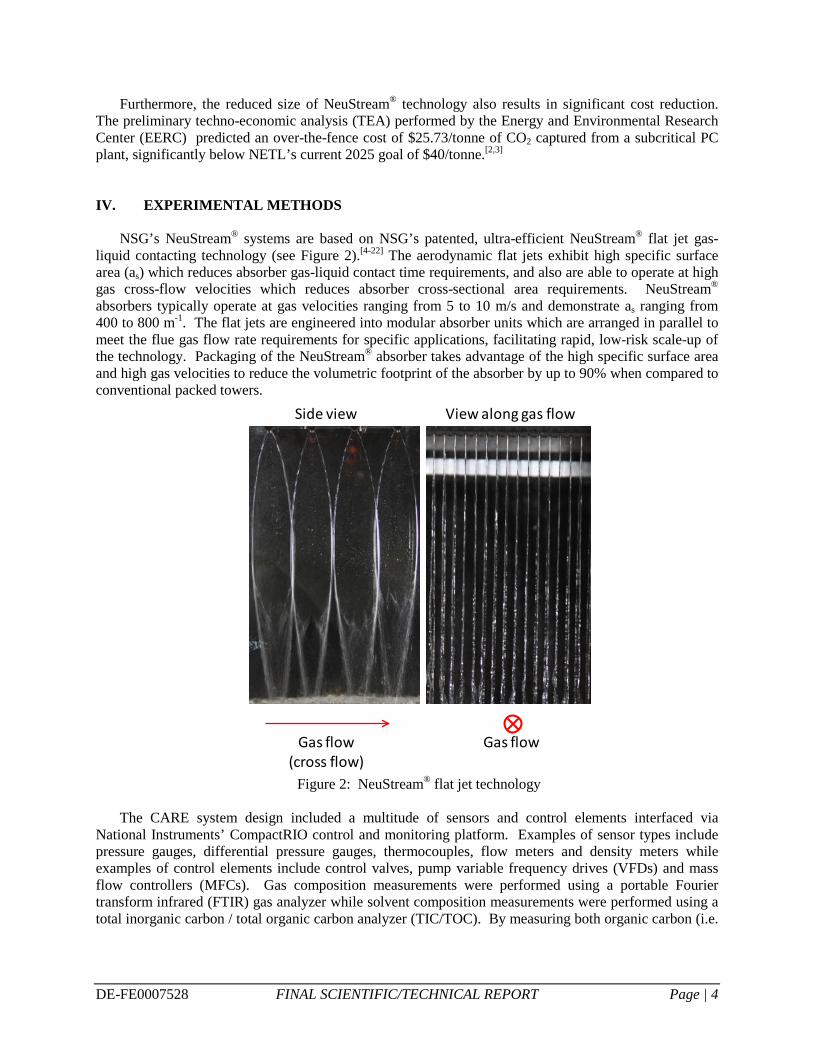
NSG’s NeuStream® systems are based on NSG’s patented, ultra-efficient NeuStream® flat jet gas-liquid contacting technology (see Figure 2).[4-22] The aerodynamic flat jets exhibit high specific surface area (as) which reduces absorber gas-liquid contact time requirements, and also are able to operate at high gas cross-flow velocities which reduces absorber cross-sectional area requirements. NeuStream® absorbers typically operate at gas velocities ranging from 5 to 10 m/s and demonstrate as ranging from 400 to 800 m-1. The flat jets are engineered into modular absorber units which are arranged in parallel to meet the flue gas flow rate requirements for specific applications, facilitating rapid, low-risk scale-up of the technology. Packaging of the NeuStream® absorber takes advantage of the high specific surface area and high gas velocities to reduce the volumetric footprint of the absorber by up to 90% when compared to conventional packed towers.
Figure 2: NeuStream® flat jet technology
The CARE system design included a multitude of sensors and control elements interfaced via
National Instruments’ CompactRIO control and monitoring platform. Examples of sensor types include pressure gauges, differential pressure gauges, thermocouples, flow meters and density meters while examples of control elements include control valves, pump variable frequency drives (VFDs) and mass flow controllers (MFCs). Gas composition measurements were performed using a portable Fourier transform infrared (FTIR) gas analyzer while solvent composition measurements were performed using a total inorganic carbon / total organic carbon analyzer (TIC/TOC). By measuring both organic carbon (i.e.
Gas flow(cross flow)
Side view
Gas flow
View along gas flow
DE-FE0007528 FINAL SCIENTIFIC/TECHNICAL REPORT Page | 5
PZ) and inorganic carbon (i.e. CO2) in the solvent samples, both PZ concentration and CO2 loading were determined.
V. RESULTS AND DISCUSSIONS
A. DESIGN PHASE
The main focus of budget period 1 (BP1) was design of the CARE system, including design verification testing (DVT) to support key design decisions. Key design requirements to meet the program objectives included 0.5MW capacity, 90% CO2 capture efficiency, 95% CO2 product purity, reduced absorber parasitic power through increased jet length and nozzle optimization, traceability to commercial scale units and a maximum cost of electricity (COE) increase of 35%.
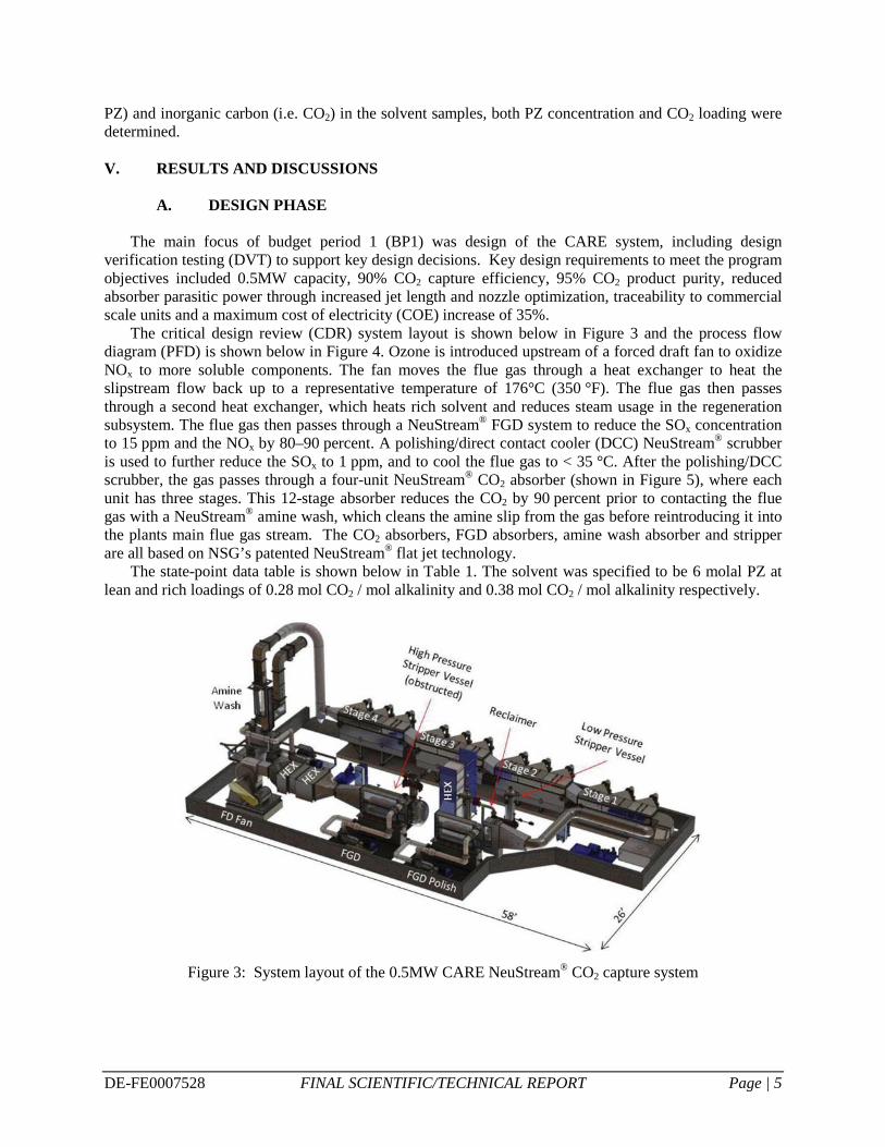
The critical design review (CDR) system layout is shown below in Figure 3 and the process flow diagram (PFD) is shown below in Figure 4. Ozone is introduced upstream of a forced draft fan to oxidize NOx to more soluble components. The fan moves the flue gas through a heat exchanger to heat the slipstream flow back up to a representative temperature of 176°C (350 °F). The flue gas then passes through a second heat exchanger, which heats rich solvent and reduces steam usage in the regeneration subsystem. The flue gas then passes through a NeuStream® FGD system to reduce the SOx concentration to 15 ppm and the NOx by 80–90 percent. A polishing/direct contact cooler (DCC) NeuStream® scrubber is used to further reduce the SOx to 1 ppm, and to cool the flue gas to < 35 °C. After the polishing/DCC scrubber, the gas passes through a four-unit NeuStream® CO2 absorber (shown in Figure 5), where each unit has three stages. This 12-stage absorber reduces the CO2 by 90 percent prior to contacting the flue gas with a NeuStream® amine wash, which cleans the amine slip from the gas before reintroducing it into the plants main flue gas stream. The CO2 absorbers, FGD absorbers, amine wash absorber and stripper are all based on NSG’s patented NeuStream® flat jet technology.
The state-point data table is shown below in Table 1. The solvent was specified to be 6 molal PZ at lean and rich loadings of 0.28 mol CO2 / mol alkalinity and 0.38 mol CO2 / mol alkalinity respectively.
Figure 3: System layout of the 0.5MW CARE NeuStream® CO2 capture system

DE-FE0007528 FINAL SCIENTIFIC/TECHNICAL REPORT Page | 6
Figure 4: CARE NeuStream® CO2 system process flow diagram (PFD)
Figure 5: Solid model of one of four NeuStream® CO2 absorber stages utilized in project CARE
Table 1: CARE NeuStream® CO2 capture system state-point data
Units Current Value[23,24] Pure Solvent (Piperazine) Molecular Weight mol-1 86.14 Normal Boiling Point °C 146 Normal Freezing Point °C 106 Vapor Pressure at 15 °C bar <0.001 Manufacturing Cost for Solvent $/kg — Working Solution* Concentration kg/kg 34% Specific Gravity (15 °C/15 °C) — 0.99 (50°C)
0.3m

DE-FE0007528 FINAL SCIENTIFIC/TECHNICAL REPORT Page | 7
Units Current Value[23,24] Specific Heat Capacity at STP kJ/kg-K 3.6 (50 °C) Viscosity at STP cP 3.6 cP (50 °C) Absorption Pressure** bar 0.101 Temperature °C 40 Equilibrium CO2 Loading mol/mol alk 0.38 Heat of Absorption kJ/mol CO2 73 Solution Viscosity cP 4.7 Desorption Pressure*** Bar 2/4 Temperature °C 150 Equilibrium CO2 Loading mol/mol alk 0.28 Heat of Desorption kJ/mol CO2 73
*unloaded PZ solution is a solid at 15°C **CO2 partial pressure in the flue gas at Drake plant ***CO2 partial pressure exiting stripper
During the design phase, the preliminary environmental health and safety (EH&S) assessment and the
preliminary techno-economic analysis (TEA) were completed by the EERC. The EH&S assessment highlighted risks and hazards associated with the PZ solvent and the system was designed accordingly to minimize risk, including the inclusion of a containment berm surrounding the processing equipment. The basis of the preliminary TEA was a 550 MW net sub-critical PC fired power plant. The TEA predicted an over-the-fence capture cost of $25.73 / tonne of CO2, significantly below NETL’s 2025 goal of $40/tonne.[2,3]
Design verification testing (DVT) was performed on a test skid that was set up at CSU’s Martin Drake power plant. The results of this testing had a maximum specific surface area achieved of 438 m-1 with jets that averaged 0.28m (11”) in length. Part of the program was to evaluate performance of longer jets, up to 0.76m (30”) in length, in order to reduce parasitic power requirements. With the DVT test skid NSG determined that increasing jet length reduced performance and resulted in an experimental surface area around 200 m-1 (see Figure 6). It was noted during the testing that at least a portion of the performance degradation associated with longer jets was caused by the increase in wall effects. In addition to the standard nozzle configuration, several other configurations were tested including variations on scrubber geometry as well as nozzle geometry, and the absorber design was configured for successful demonstration using the highest possible surface area configuration (about 450 m-1) and the most economical option (lower surface area, but significant drop in energy demand).

DE-FE0007528 FINAL SCIENTIFIC/TECHNICAL REPORT Page | 8
Figure 6: Experimental surface area as a function of jet length
B. CONSTRUCTION PHASE
The main focus of budget period 2 (BP2) was the procurement, fabrication, construction and installation of the system at CSU’s Martin Drake PC power plant and integration with Unit 7’s flue gas. NSG relied on its past experience constructing emissions control systems at coal plants and on its excellent working relationship with CSU to successfully drive the system construction to completion. Proper safety protocol was followed throughout the construction, and the project was completed without incident. Figure 7 through Figure 10 below detail the construction and the major pieces of equipment installed at the Martin Drake power plant.
Figure 7: CARE system enclosure with containment berm at CSU’s Martin Drake power plant
0
50
100
150
200
250
300
350
400
450
0 0.1 0.2 0.3 0.4 0.5 0.6 0.7 0.8 0.9
Expe
rimen
tal a
s, m
-1
Average Jet Length, m

DE-FE0007528 FINAL SCIENTIFIC/TECHNICAL REPORT Page | 9
Figure 8: CARE NeuStream® FGD absorbers installed at the Drake plant
Figure 9: CARE NeuStream® CO2 absorbers installed at the Drake plant
Figure 10: CARE stripper unit installed at the Drake plant
DE-FE0007528 FINAL SCIENTIFIC/TECHNICAL REPORT Page | 10
C. TESTING PHASE
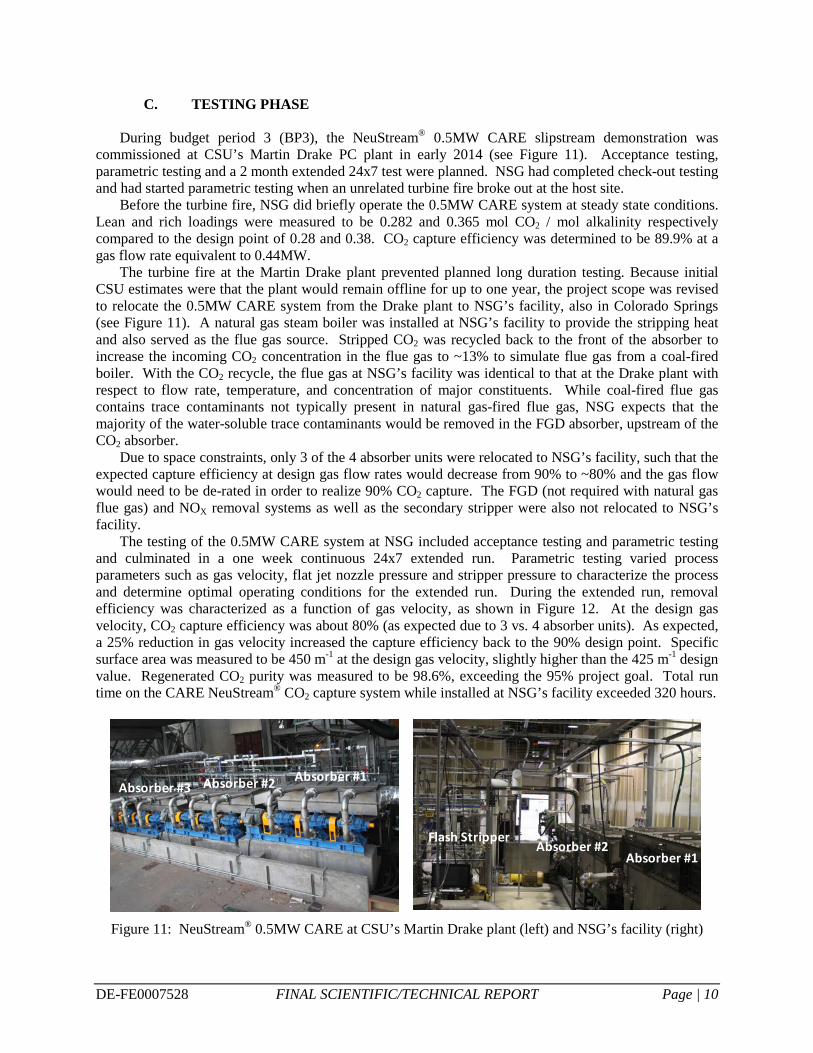
During budget period 3 (BP3), the NeuStream® 0.5MW CARE slipstream demonstration was commissioned at CSU’s Martin Drake PC plant in early 2014 (see Figure 11). Acceptance testing, parametric testing and a 2 month extended 24x7 test were planned. NSG had completed check-out testing and had started parametric testing when an unrelated turbine fire broke out at the host site.
Before the turbine fire, NSG did briefly operate the 0.5MW CARE system at steady state conditions. Lean and rich loadings were measured to be 0.282 and 0.365 mol CO2 / mol alkalinity respectively compared to the design point of 0.28 and 0.38. CO2 capture efficiency was determined to be 89.9% at a gas flow rate equivalent to 0.44MW.
The turbine fire at the Martin Drake plant prevented planned long duration testing. Because initial CSU estimates were that the plant would remain offline for up to one year, the project scope was revised to relocate the 0.5MW CARE system from the Drake plant to NSG’s facility, also in Colorado Springs (see Figure 11). A natural gas steam boiler was installed at NSG’s facility to provide the stripping heat and also served as the flue gas source. Stripped CO2 was recycled back to the front of the absorber to increase the incoming CO2 concentration in the flue gas to ~13% to simulate flue gas from a coal-fired boiler. With the CO2 recycle, the flue gas at NSG’s facility was identical to that at the Drake plant with respect to flow rate, temperature, and concentration of major constituents. While coal-fired flue gas contains trace contaminants not typically present in natural gas-fired flue gas, NSG expects that the majority of the water-soluble trace contaminants would be removed in the FGD absorber, upstream of the CO2 absorber.
Due to space constraints, only 3 of the 4 absorber units were relocated to NSG’s facility, such that the expected capture efficiency at design gas flow rates would decrease from 90% to ~80% and the gas flow would need to be de-rated in order to realize 90% CO2 capture. The FGD (not required with natural gas flue gas) and NOX removal systems as well as the secondary stripper were also not relocated to NSG’s facility.
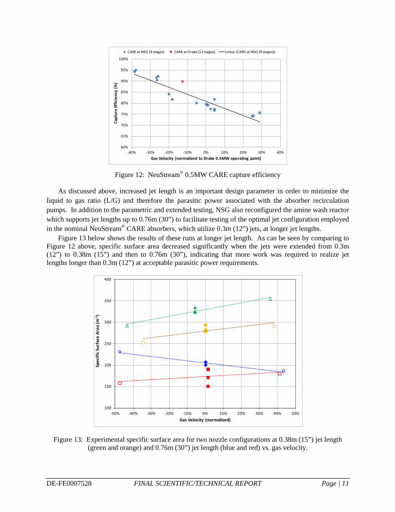
The testing of the 0.5MW CARE system at NSG included acceptance testing and parametric testing and culminated in a one week continuous 24x7 extended run. Parametric testing varied process parameters such as gas velocity, flat jet nozzle pressure and stripper pressure to characterize the process and determine optimal operating conditions for the extended run. During the extended run, removal efficiency was characterized as a function of gas velocity, as shown in Figure 12. At the design gas velocity, CO2 capture efficiency was about 80% (as expected due to 3 vs. 4 absorber units). As expected, a 25% reduction in gas velocity increased the capture efficiency back to the 90% design point. Specific surface area was measured to be 450 m-1 at the design gas velocity, slightly higher than the 425 m-1 design value. Regenerated CO2 purity was measured to be 98.6%, exceeding the 95% project goal. Total run time on the CARE NeuStream® CO2 capture system while installed at NSG’s facility exceeded 320 hours.
Figure 11: NeuStream® 0.5MW CARE at CSU’s Martin Drake plant (left) and NSG’s facility (right)
Absorber #1Absorber #2Absorber #3
Absorber #1Absorber #2
Flash Stripper
DE-FE0007528 FINAL SCIENTIFIC/TECHNICAL REPORT Page | 11
Figure 12: NeuStream® 0.5MW CARE capture efficiency
As discussed above, increased jet length is an important design parameter in order to minimize the
liquid to gas ratio (L/G) and therefore the parasitic power associated with the absorber recirculation pumps. In addition to the parametric and extended testing, NSG also reconfigured the amine wash reactor which supports jet lengths up to 0.76m (30”) to facilitate testing of the optimal jet configuration employed in the nominal NeuStream® CARE absorbers, which utilize 0.3m (12”) jets, at longer jet lengths.
Figure 13 below shows the results of these runs at longer jet length. As can be seen by comparing to Figure 12 above, specific surface area decreased significantly when the jets were extended from 0.3m (12”) to 0.38m (15”) and then to 0.76m (30”), indicating that more work was required to realize jet lengths longer than 0.3m (12”) at acceptable parasitic power requirements.
Figure 13: Experimental specific surface area for two nozzle configurations at 0.38m (15”) jet length (green and orange) and 0.76m (30”) jet length (blue and red) vs. gas velocity.
60%
65%
70%
75%
80%
85%
90%
95%
100%
-40% -30% -20% -10% 0% 10% 20% 30% 40%
Capt
ure
Effic
ienc
y (%
)
Gas Velocity (normalized to Drake 0.5MW operating point)
CARE at NSG (9 stages) CARE at Drake (12 stages) Linear (CARE at NSG (9 stages))
100
150
200
250
300
350
400
-50% -40% -30% -20% -10% 0% 10% 20% 30% 40% 50%
Spec
ific S
urfa
ce A
rea
(m-1
)
Gas Velocity (normalized)

DE-FE0007528 FINAL SCIENTIFIC/TECHNICAL REPORT Page | 12
While the CARE CDR design achieved the program objectives, it did not fully meet our scaling objectives as laid out in our original proposal with respect to parasitic power requirements for the absorber recirculation pumps. Therefore, in parallel with the CARE program, NSG conducted a major, internally funded, internal research and development (IR&D) effort that directly supported the CARE statement of project objectives (SOPO) to decrease the parasitic power associated with the absorber recirculation pumps. Through this IR&D effort, NSG successfully engineered optimized jet nozzles coupled with a jet stabilization technique that reduces liquid flow per nozzle by a factor of 3, reduces nozzle driving pressure by a factor of 7 and increases jet length by a factor of 3.
The sum of these improvements results in an advanced NeuStream® absorber configuration that demonstrates a specific surface area of 400 m-1, while reducing parasitic power requirements associated with the recirculation pumps by a factor of 10 when compared to the technology demonstrated during the 0.5MW CARE project. Table 2 contains performance specifications for the nominal CARE vs. stabilized jets for the 0.5MW CARE system and a conceptual 550MW NeuStream® design featuring eight vertical levels.
Table 2: Performance specifications for NeuStream® nominal CARE jets vs. stabilized jets
The advanced, stabilized jet configuration was thoroughly tested on NSG’s large bench scale test stand, which features a 0.25m (10”) jet length, with PZ solvent. Figure 14 contains a comparison of the as attained with the CARE nozzle configuration vs. the advanced stabilized jets. Note that the slightly lower as attained with the advanced jets is tolerable due to the significant decrease in parasitic power.
NSG recently converted the amine wash reactor of the 0.5MW CARE test stand into a single stage for CO2 absorption to facilitate testing of the advanced, stabilized jets with a jet length of 0.76m (30”). As shown in Figure 14, a preliminary test resulted in a measured as of 360m-1, significantly higher as than was determined for 0.76m jet lengths during the CARE design verification testing in BP1 and BP2 as well as the more recent testing summarized in Figure 13.
When compared to traditional packed tower absorber technology, the NeuStream® CO2 absorber with advanced stabilized jets exhibits higher effective as (400-500m-1 vs. 100-200m-1)[26,27] and also operates at higher gas velocity, reducing absorber size by up to 90% and system cost by 50% or greater.[1,2] The higher as also reduces contact length in the absorber, which at NeuStream®’s low gas-side pressure drop of 0.25kPa/m equates to a significant decrease in booster fan power requirements (~70% decrease when compared to Boundary Dam).[28] Even though packed towers typically have no internal recycle of liquid, NSG estimates that NeuStream® CO2 capture parasitic power requirements for the fan and solvent pumps are 35% less than those associated with a packed tower application. Moreover, NSG performed tests with multiple solvents to demonstrate that the benefits of the NeuStream® technology are independent of the solvent employed.
0.5MW CARE1 absorber level
0.5MW CARE1 absorber level
550MW NeuStream®8 absorber levels
Jet Type nominal stabilized stabilizedJet Length (m) 0.3 0.76 0.91
Total recirculation pump power (kW) 82 18 3129Absorber Capacity (effective MW(net))* 1 2 563
Parasitic power (% of net) 8.17% 0.84% 0.56%*NETL case 11 conditions[25]. CARE is oversized due to CSU altitude and flow/MW compared to NETL basecase

DE-FE0007528 FINAL SCIENTIFIC/TECHNICAL REPORT Page | 13
Figure 14: Performance comparison between 0.5MW CARE jets (blue) and stabilized jets (red and
green), 0.25m (10”) jet length (left); Stabilized jets in 0.5MW CARE system, 0.76m (30”) jet length, steady-state test (right).
In addition to the testing performed with concentrated PZ described above, NSG investigated the
performance of several other solvents to show that the NeuStream® absorber technology is widely applicable to a variety of common CO2 capture solvents. Additional solvents tested included a monoethanolamine (MEA) / triethylene glycol (TEG) blend, a PZ / potassium carbonate blend, and Akermin’s proprietary solvent.
NSG tested a solvent blend of MEA and TEG in water in the NeuStream® 0.5MW CARE system. Testing was stopped almost immediately due to the formation of a significant aerosol cloud in the absorber that was not being captured by the amine wash. This aerosol was not observed during preliminary testing of the MEA/TEG solvent blend on NSG’s large bench-scale NeuStream® test stand (0.1 Nm3/s, 200 scfm).
The main difference between the large bench scale system and the 0.5MW CARE system is the source of the flue gas supply. The large bench scale system flue gas is provided by a diesel generator which is fitted with an inline combustion filter to eliminate particulate emissions, while the natural gas boiler used to generate the flue gas for the CARE system does not have any particulate control. The formation of aerosols when using MEA solvent in the presence of very small particulates in the flue gas is well documented in the literature.
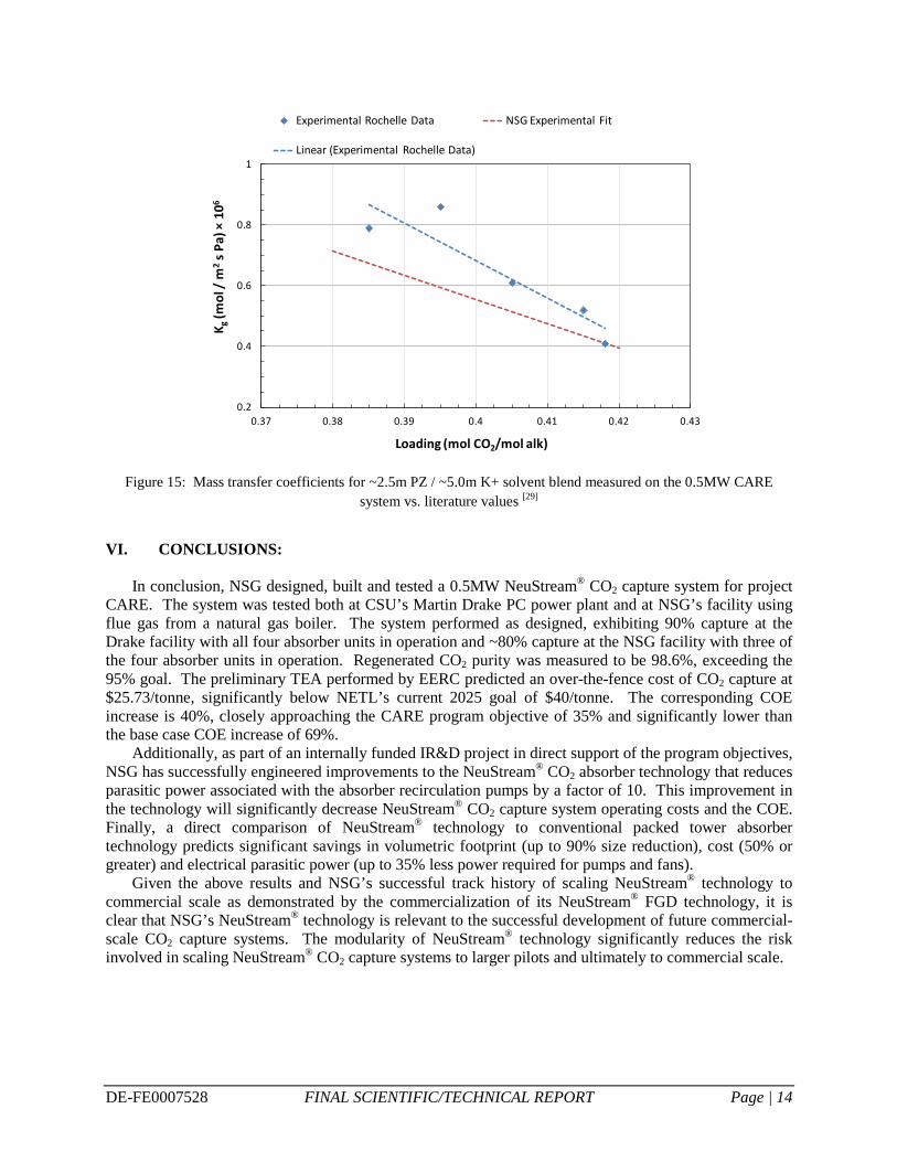
NSG also tested a blend of 2.6m PZ and potassium carbonate (4.25m K+) in the NeuStream® 0.5MW CARE system. To facilitate determination of the mass transfer coefficients, specific surface area was assumed to be equivalent to that measured during PZ testing. In general, mass transfer coefficients agreed with those published by Rochelle for a 2.5m PZ / 5.0m K+ solvent blend as shown in Figure 15. [29]
Finally, NSG worked with Akermin, Inc. to test their proprietary solvent in NSG’s large bench scale (0.1 Nm3/s, 200 scfm) NeuStream® test stand. Prior to the start of the testing, minor modifications were made to the test stand to facilitate the testing of Akermin’s solvent. No compatibility issues between Akermin’s solvent and the NeuStream® absorber were observed. The data is considered proprietary to Akermin.
0
100
200
300
400
500
600
700
800
900
1000
0.00 10.00 20.00 30.00 40.00 50.00 60.00
Spec
ific S
urfa
ce A
rea,
as
(m-1
)
Elapsed Time (min)
0
100
200
300
400
500
600
0.00 2.00 4.00 6.00 8.00 10.00 12.00 14.00 16.00 18.00 20.00
Spec
ific S
urfa
ce A
rea,
as
(m-1
)
Elapsed Time (min)
DE-FE0007528 FINAL SCIENTIFIC/TECHNICAL REPORT Page | 14
Figure 15: Mass transfer coefficients for ~2.5m PZ / ~5.0m K+ solvent blend measured on the 0.5MW CARE
system vs. literature values [29]
VI. CONCLUSIONS:
In conclusion, NSG designed, built and tested a 0.5MW NeuStream® CO2 capture system for project CARE. The system was tested both at CSU’s Martin Drake PC power plant and at NSG’s facility using flue gas from a natural gas boiler. The system performed as designed, exhibiting 90% capture at the Drake facility with all four absorber units in operation and ~80% capture at the NSG facility with three of the four absorber units in operation. Regenerated CO2 purity was measured to be 98.6%, exceeding the 95% goal. The preliminary TEA performed by EERC predicted an over-the-fence cost of CO2 capture at $25.73/tonne, significantly below NETL’s current 2025 goal of $40/tonne. The corresponding COE increase is 40%, closely approaching the CARE program objective of 35% and significantly lower than the base case COE increase of 69%.
Additionally, as part of an internally funded IR&D project in direct support of the program objectives, NSG has successfully engineered improvements to the NeuStream® CO2 absorber technology that reduces parasitic power associated with the absorber recirculation pumps by a factor of 10. This improvement in the technology will significantly decrease NeuStream® CO2 capture system operating costs and the COE. Finally, a direct comparison of NeuStream® technology to conventional packed tower absorber technology predicts significant savings in volumetric footprint (up to 90% size reduction), cost (50% or greater) and electrical parasitic power (up to 35% less power required for pumps and fans).
Given the above results and NSG’s successful track history of scaling NeuStream® technology to commercial scale as demonstrated by the commercialization of its NeuStream® FGD technology, it is clear that NSG’s NeuStream® technology is relevant to the successful development of future commercial-scale CO2 capture systems. The modularity of NeuStream® technology significantly reduces the risk involved in scaling NeuStream® CO2 capture systems to larger pilots and ultimately to commercial scale.
0.2
0.4
0.6
0.8
1
0.37 0.38 0.39 0.4 0.41 0.42 0.43
K g(m
ol /
m2
s Pa)
×10
6
Loading (mol CO2/mol alk)
Experimental Rochelle Data NSG Experimental Fit
Linear (Experimental Rochelle Data)

DE-FE0007528 FINAL SCIENTIFIC/TECHNICAL REPORT Page | 15
VII. REFERENCES:
1. Couturier, Guy and DMello, Mark, (SNC-Lavalin), “From Engineering to Procurement to Construction of the Boundary Dam Carbon Capture System”, SaskPower CCS Consortium, 2013 Information and Planning Symposium, May 21, 2013.
2. EERC, “Techno-Economic Modeling of Neumann System Group’s CO2 Capture Process for Carbon Absorber Retrofit Equipment (CARE)”, prepared for Neumann Systems Group, DOE/NETL Contract No. DE-FE0007528, 2012.
3. DOE/NETL, “Financial Assistance Funding Opportunity Announcement: Small and Large Scale Pilots for Reducing the Cost of CO2 Capture and Compression”, DE-FOA-0001190, Issued 2/11/15.
4. McDermott, W.E., Neumann, D.K., and Henshaw, T.L., inventors; Neumann Information Systems, Inc. assignee, “Two Phase Reactor,” United States patent US 7,379,487. 2008.
5. Neumann, D. K., Miller, N. J., Nizamov, B.R., Henshaw, T. L., Awtry, A.R., Brasseur, J.K., Hobbs, K.R., Tobias, J.A., and McDermott, W.E., inventors; Neumann Systems Group, Inc., assignee, “Gas Liquid Contactor and Effluent Cleaning System and Method,” United States patent US 7,866,638. 2011.
6. McDermott, W.E., Neumann, D.K., and Henshaw, T.L., inventors; Neumann Systems Group, Inc. assignee; “Two Phase Reactor,” United States patent US 7,871,063. 2011.
7. Neumann, D. K., Awtry, A.R., Brasseur, J.K., Hobbs, K.R., Nizamov, B.R., and Henshaw, T. L., inventors, Neumann Systems Group, Inc., assignee, “Method of Separating at Least Two Fluids with an Apparatus”, United States patent US 8,088,292. 2012.
8. Neumann, D.K., Miller N.J., Nizamov B.R., Henshaw, T. L., Awtry, A.R., Brasseur, J.K., Hobbs, K.R., Tobias, J.A., and McDermott, W.E., inventors; Neumann Systems Group, Inc., assignee, “Gas Liquid Contactor and Effluent Cleaning System and Method”, United States patent US 8,105,419. 2012.
9. Neumann, D.K., Awtry, A.R., Brasseur, J.K., Hobbs, K.R., Nizamov, B.R., and Henshaw, T.L., inventors; Neumann Systems Group, Inc., assignee, “Gas-Liquid Contactor Apparatus and Nozzle Plate,” United States patent US 8,113,491. 2012.
10. Neumann, D. K., Awtry, A.R., Brasseur, J.K., Hobbs, K.R., Nizamov, B.R., and Henshaw, T.L, inventors; Neumann Systems Group, Inc., assignee, “Method of Processing Gas Phase Molecules by Gas-Liquid Contact”, United States patent US 8,216,346. 2012.
11. Neumann, D.K., Awtry, A.R., Brasseur, J.K., Hobbs, K.R., Nizamov, B.R., and Henshaw, T.L., inventors; Neumann Systems Group, Inc., assignee, “Method of Processing Molecules with a Gas-Liquid Contactor” United States patent US 8,216,347. 2012.
12. Neumann, D.K., Awtry, A.R., Brasseur, J.K., Hobbs, K.R., Nizamov, B.R., and Henshaw, T.L., inventors; Neumann Systems Group, Inc., assignee, “Method for Enhancing a Gas Liquid Contactor” United States patent US 8,262,777. 2012.
13. McDermott, W.E., Neumann, D.K., and Henshaw, T.L., inventors; Neumann Systems Group, Inc., assignee, “Two Phase Reactor”, United States patent US 8,323,381. 2012.
14. Neumann, D.K., Miller N.J., Nizamov B.R., Henshaw, T. L., Awtry, A.R., Brasseur, J.K., Hobbs, K.R., Tobias, J.A., and McDermott, W.E., inventors; Neumann Systems Group, Inc., assignee, “Gas Liquid Contactor and Effluent Cleaning System and Method” United States patent US 8,336,863. 2012.
15. Neumann, D.K., Hobbs, K.R., and Courtright, J.L., inventors; Neumann Systems Group, Inc., assignee, “Gas Liquid Contactor and Method Thereof”, United States patent US 8,398,059. 2013.
16. Neumann, D.K., Hobbs, K.R., and Courtright, J.L., inventors; Neumann Systems Group, Inc., assignee, “Gas Liquid Contactor and Method Thereof”, United States patent US 8,668,766. 2014.

DE-FE0007528 FINAL SCIENTIFIC/TECHNICAL REPORT Page | 16
17. McDermott, W.E., Neumann, D.K., and Henshaw, T.L., inventors; Neumann Systems Group, Inc., assignee, “Two Phase Reactor”, United States patent US 8,814,146. 2014.
18. Neumann, D.K., Nizamov, B.R., Henshaw, T.L. and Anderson, J.L., inventors; Neumann Systems Group, Inc., assignee, “Indirect & Direct Method of Sequestering Contaminants,” United States patent US 8,864,876. 2014.
19. Neumann, D.K., Miller, N.J., Nizamov, B.R., Henshaw, T.L., Awtry, A.R., Brasseur, J.K., Hobbs, K.R., Tobias, J.A., and McDermott, W.E., inventors; Neumann Systems Group, Inc., assignee, “Gas Liquid Contactor and Effluent Cleaning System and Method,” World patent WO 2010/036436. 2010.
20. Neumann, D.K., Awtry, A.R., Brasseur, J.K., Hobbs, K.R., Nizamov, B.R., and Henshaw, T.L., inventors; Neumann Systems Group, Inc., assignee, “Apparatus and Method Thereof”, World patent, WO 2010/037037. 2010.
21. Neumann, D.K., Nizamov, B.R., Henshaw, T.L., and Anderson, J.L., inventors; Neumann Systems Group, Inc., assignee, “Indirect & Direct Method of Sequestering Contaminants,” World patent WO 2010/037040. 2010.
22. Neumann, D.K., Hobbs, K.R., and Courtright, J.L., inventors; Neumann Systems Group, Inc., assignee, “Gas Liquid Contactor and Method Thereof ”, World patent WO 2010/037043. 2010.
23. Dugas, Ross E., “CO2 Absorption, Desorption, and Diffusion in Aqueous Piperazine and Monoethanolamine”, PhD Thesis, University of Texas, 2009.
24. Van Wagener, David H., “Stripper Modeling for CO2 Removal Using Monoethanolamine and Piperazine Solvents”, PhD Thesis, University of Texas, 2011.
25. NETL, “Cost and Performance Baseline for Fossil Energy Plants. Volume 1: Bituminous Coal and Natural Gas to Electricity”, Revision 2a, September 2013. DOE/NETL-2010/1397.
26. Kolev, N., Nakov, S., Ljutzkanov, L., and Kolev, D., “Comparison of the Effective Surface Area of some Highly Efficient Random Packings Third and Fourth Generation”, IChemE, Symposium Series No. 152, 2006.
27. Tsai, R., Seibert, A., Eldrige, R. and Rochelle, G., “A Dimensionless Model for Predicting the Mass-Transfer Area of Structured Packing”, AIChE Journal, Vol. 57, No. 5, pp.1173-1184, 2011.
28. Cansolv Technologies, Inc., “SaskPower Boundary Dam 3 Project Update and Some Lessons Learned”, March 2013.
29. Rochelle, et. al., “CO2 Capture by Absorption with Potassium Carbonate”, Final Report, DE-FC26-02NT41440, 2007.
VIII. LIST OF ACRONYMS AND ABBREVIATIONS
as: Specific surface area BP: Budget period CARE: Carbon Absorber Retrofit Equipment CDR: Critical design review CO2: Carbon dioxide COE: Cost of electricity CSU: Colorado Springs Utilities DCC: Direct contact cooler DVT: Design verification testing EERC: Energy & Environmental Research Center (University of North Dakota) EH&S: Environmental health and safety FGD: Flue gas desulfurization FTIR: Fourier transform infrared spectroscopy IR&D: Internal research & development L/G: Liquid to gas ratio MFC: Mass flow controller
DE-FE0007528 FINAL SCIENTIFIC/TECHNICAL REPORT Page | 17
NG: Natural gas NSG: Neumann Systems’ Group, Inc. PC: Pulverized coal PFD: Process flow diagram PZ: Piperazine SOPO: Statement of project objectives TEA: Techno-economic analysis TIC/TOC: Total inorganic carbon / total organic carbon analyzer VFD: Variable frequency drive