cast cutter 1 - stryker...
TRANSCRIPT

\ \ \ \ \ \ \ \ \ \ \ \ \ \ \ \ \ \ \ \ \ \ \ \ \ \ \ \ \ \ \ \ \ \ \ \ \ \ \ \ \ \ \ \ \ \ \ \ \ \Cast Cutter
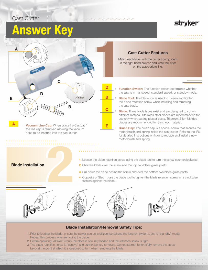
1 Cast Cutter Features
Match each letter with the correct component in the right hand column and write the letter
on the appropriate line.
_________ :
_________ :
_________ :
_________ :
2Blade Installation
Function Switch: The function switch determines whether the saw is in highspeed, standard speed, or standby mode. Blade Tool: The blade tool is used to loosen and tighten the blade retention screw when installing and removing the saw blade. Blade: Three blade types exist and are designed to cut on different material. Stainless steel blades are recommended for use only when cutting plaster casts. Tritanium & Ion Nitrided blades are recommended for Synthetic material. Brush Cap: The brush cap is a special screw that secures the motor brush and spring inside the cast cutter. Refer to the IFU for detailed instructions on how to replace and install a new motor brush and spring.
_________ : Vacuum Line Cap: When using the CastVac™ the line cap is removed allowing the vacuum hose to be inserted into the cast cutter.
1. Loosen the blade retention screw using the blade tool to turn the screw counterclockwise.
2. Slide the blade over the screw and the top two blade guide posts.
3. Pull down the blade behind the screw and over the bottom two blade guide posts.
4. Opposite of Step 1, use the blade tool to tighten the blade retention screw in a clockwise fashion against the blade.
Blade Installation/Removal Safety Tips: 1. Prior to loading the blade, ensure the power source is disconnected and the function switch is set to “standby” mode. Repeat this process when removing the blade. 2. Before operating, ALWAYS verify the blade is securely loaded and the retention screw is tight.3. The blade retention screw is “captive” and cannot be fully removed. Do not attempt to forcefully remove the screw beyond the point at which it is designed to turn when removing the blade.
ED
A
C
B

Literature Number: 9100-003-463 Rev. NoneUnDe/P.S.
Copyright © 2015 StrykerPrinted in USA
Stryker Instruments4100 East Milham AvenueKalamazoo, MI 49001 USAt: 269 323 7700 f: 800 999 3811toll free: 800 253 3210
www.Stryker.com
***The Stryker Cast Cutter Proficiency test is an optional educational tool and is not designed to replace the Instructions for Use (IFU). For detailed instructions on sterilization, troubleshooting, and system features always consult the IFU.
1. The cast cutter does not operate. a. The motor brushes are installed in the wrong orientation. b. The function switch is broken or set in “standby” mode. c. The fuse is blown. d. All of the above.
2. The blade does not cut smoothly or adaquetely. a. The person using the Cast Cutter is not strong enough to make the necessary cut. b. The blade itself is worn and needs to be replaced. c. The humidity in the air is altering the efficiency of the cut. d. The person using the Cast Cutter drank too much coffee and is shaking uncontrollably.
3. The blade slips when making the cut. a. Somebody used a lubricant on the blade making it slippery. b. The person operating the Cast Cutter doesn’t know what they’re doing. c. The blade guide posts are worn and the Cast Cutter should be returned to Stryker for repair. d. The cast material is wet and the blade can’t get a good grip.
4Troubleshooting Quiz
Date: Date:/ / / /
P r i n t N a m e P r i n t N a m e
Completed By: Supervisor/Trainer (if required):
S i g n a t u r e S i g n a t u r e
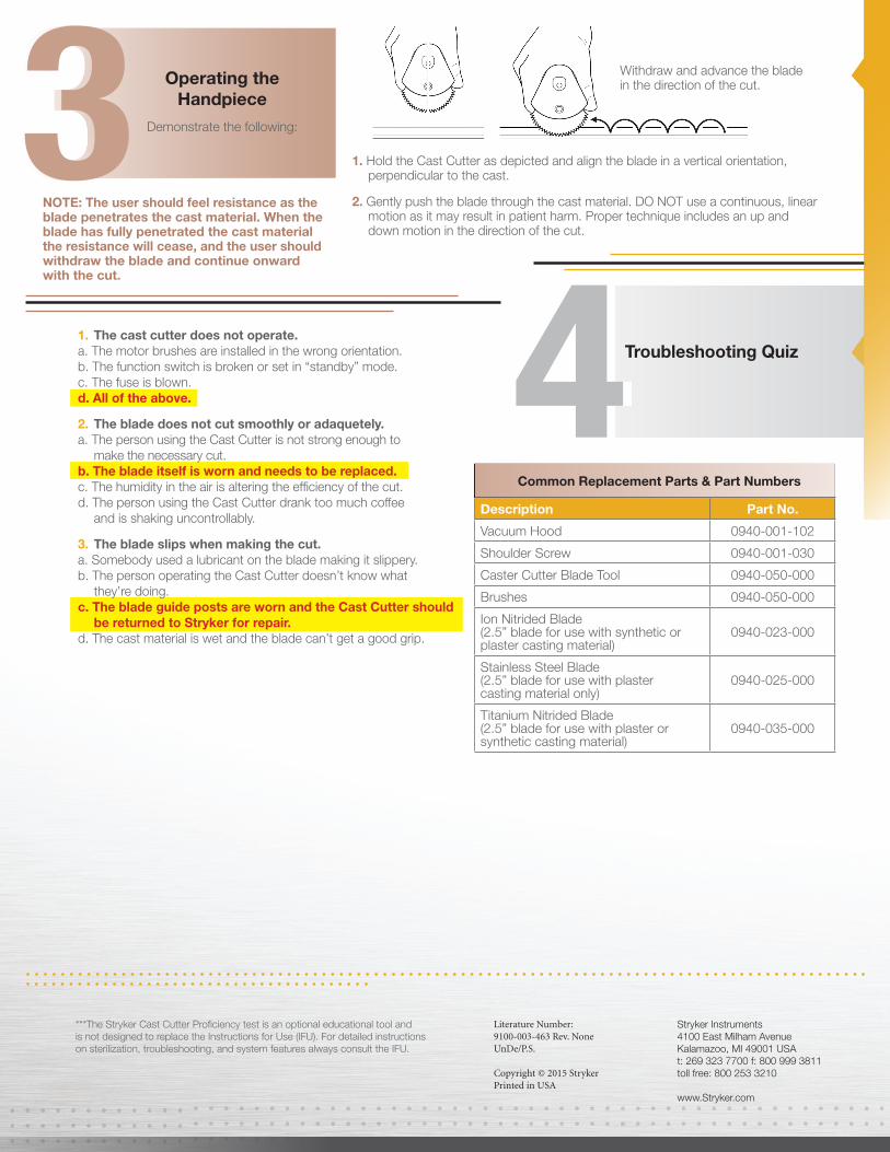
1. Hold the Cast Cutter as depicted and align the blade in a vertical orientation, perpendicular to the cast.
2. Gently push the blade through the cast material. DO NOT use a continuous, linear motion as it may result in patient harm. Proper technique includes an up and down motion in the direction of the cut.
NOTE: The user should feel resistance as the blade penetrates the cast material. When the blade has fully penetrated the cast material the resistance will cease, and the user should withdraw the blade and continue onward with the cut.
Operating the Handpiece
Demonstrate the following:3 Withdraw and advance the blade in the direction of the cut.
Description Part No.
Vacuum Hood 0940-001-102
Shoulder Screw 0940-001-030
Caster Cutter Blade Tool 0940-050-000
Brushes 0940-050-000
Ion Nitrided Blade (2.5” blade for use with synthetic or plaster casting material)
0940-023-000
Stainless Steel Blade (2.5” blade for use with plaster casting material only)
0940-025-000
Titanium Nitrided Blade (2.5” blade for use with plaster or synthetic casting material)
0940-035-000
For additional troubleshooting tips and suggestions consult the Instructions for Use or
contact your local ProCare® Specialist.
Common Replacement Parts & Part Numbers
\ \ \ \ \ \ \ \ \ \ \ \ \ \ \ \ \ \ \ \ \ \ \ \ \ \ \ \ \ \ \ \ \ \ \ \ \ \ \ \ \ \ \ \ \ \ \ \ \ \Cast Cutter
1 Cast Cutter Features
Match each letter with the correct component in the right hand column and write the letter
on the appropriate line.
2Blade Installation
Function Switch: The function switch determines whether the saw is in highspeed, standard speed, or standby mode. Blade Tool: The blade tool is used to loosen and tighten the blade retention screw when installing and removing the saw blade. Blade: Three blade types exist and are designed to cut on different material. Stainless steel blades are recommended for use only when cutting plaster casts. Tritanium & Ion Nitrided blades are recommended for Synthetic material. Brush Cap: The brush cap is a special screw that secures the motor brush and spring inside the cast cutter. Refer to the IFU for detailed instructions on how to replace and install a new motor brush and spring.
Vacuum Line Cap: When using the CastVac™ the line cap is removed allowing the vacuum hose to be inserted into the cast cutter.
1. Loosen the blade retention screw using the blade tool to turn the screw counterclockwise.
2. Slide the blade over the screw and the top two blade guide posts.
3. Pull down the blade behind the screw and over the bottom two blade guide posts.
4. Opposite of Step 1, use the blade tool to tighten the blade retention screw in a clockwise fashion against the blade.
Blade Installation/Removal Safety Tips: 1. Prior to loading the blade, ensure the power source is disconnected and the function switch is set to “standby” mode. Repeat this process when removing the blade. 2. Before operating, ALWAYS verify the blade is securely loaded and the retention screw is tight.3. The blade retention screw is “captive” and cannot be fully removed. Do not attempt to forcefully remove the screw beyond the point at which it is designed to turn when removing the blade.
ED
A
C
B
D
B
C
EA_________ :
_________ :
_________ :
_________ :
_________ :
Literature Number: 9100-003-463 Rev. NoneUnDe/P.S.
Copyright © 2015 StrykerPrinted in USA
Stryker Instruments4100 East Milham AvenueKalamazoo, MI 49001 USAt: 269 323 7700 f: 800 999 3811toll free: 800 253 3210
www.Stryker.com
***The Stryker Cast Cutter Proficiency test is an optional educational tool and is not designed to replace the Instructions for Use (IFU). For detailed instructions on sterilization, troubleshooting, and system features always consult the IFU.
4Troubleshooting Quiz
1. Hold the Cast Cutter as depicted and align the blade in a vertical orientation, perpendicular to the cast.
2. Gently push the blade through the cast material. DO NOT use a continuous, linear motion as it may result in patient harm. Proper technique includes an up and down motion in the direction of the cut.
NOTE: The user should feel resistance as the blade penetrates the cast material. When the blade has fully penetrated the cast material the resistance will cease, and the user should withdraw the blade and continue onward with the cut.
Operating the Handpiece
Demonstrate the following:3 Withdraw and advance the blade in the direction of the cut.
Description Part No.
Vacuum Hood 0940-001-102
Shoulder Screw 0940-001-030
Caster Cutter Blade Tool 0940-050-000
Brushes 0940-050-000
Ion Nitrided Blade (2.5” blade for use with synthetic or plaster casting material)
0940-023-000
Stainless Steel Blade (2.5” blade for use with plaster casting material only)
0940-025-000
Titanium Nitrided Blade (2.5” blade for use with plaster or synthetic casting material)
0940-035-000
Common Replacement Parts & Part Numbers
1. The cast cutter does not operate. a. The motor brushes are installed in the wrong orientation. b. The function switch is broken or set in “standby” mode. c. The fuse is blown. d. All of the above.
2. The blade does not cut smoothly or adaquetely. a. The person using the Cast Cutter is not strong enough to make the necessary cut. b. The blade itself is worn and needs to be replaced. c. The humidity in the air is altering the efficiency of the cut. d. The person using the Cast Cutter drank too much coffee and is shaking uncontrollably.
3. The blade slips when making the cut. a. Somebody used a lubricant on the blade making it slippery. b. The person operating the Cast Cutter doesn’t know what they’re doing. c. The blade guide posts are worn and the Cast Cutter should be returned to Stryker for repair. d. The cast material is wet and the blade can’t get a good grip.