cefil’air pneumatic seals - rubber technologyrubbertechnology.info/en/brochures/eriks - cefilair -...
TRANSCRIPT

S E A L I N G T E C H N O L O G I E S
CEFIL’AIR ® PNEUMATIC SEALS

Garlock Sealing TechnologiesThe demands of modern applications make the
choice of the right sealing product an important consideration, both in the design of new equipment andin choosing the new products which will replace thoseno longer suitable.
This brochure provides some typical examples ofappropriate applications, but is not limited to be a warranty of performance. All specific uses of sealingproducts require independent study and specific evaluation for suitability.
Garlock will provide the technical assistance of itsapplications engineers, who will give you specific recommendations. Please consult us. We are ready tohelp you make the right choice. Choosing the wrongsealing product can result in property damage and/orserious personal injury. Do not rely on the general criteria, which may not suit your application as well asone that Garlock Engineering can help you choose.Reliability and service to our customers is what theGarlock name means.
Let us help you choose the right product for yourapplication.
Inflatable Seals You Can Depend OnGarlock Inflatable Seals are manufactured in
completely modernized facilities. Tight quality controlsare used to assure product conformance to specifications and uniformity that results in unvarying performance on the job. Garlock is registered to ISO-9002-94 standards and is audited by the NuclearProcurement and Issues Committee (NUPIC).
Today�s environmental concerns demand positive seals. Garlock Inflatable Seals provide thatassurance, and perform with proven reliability. Whetheryour industry is chemical processing, hydrocarbon processing, power generation, pulp and paper, microelectronics or transportation, Garlock inflatableseals are the logical choice.
For products not listed in this catalog, contactGarlock at 1-800-448-6688.

CEFIL’AIR PNEUMATIC SEALSContentsINTRODUCTION . . . . . . . . . . . . . . . . . . . . . . . . . . . . . 2
MANUFACTURING . . . . . . . . . . . . . . . . . . . . . . . . . . . 2
OPERATION . . . . . . . . . . . . . . . . . . . . . . . . . . . . . . . 2
APPLICATIONSExamples of Sealing . . . . . . . . . . . . . . . . . . . . . . . . . . 3Examples of Handling . . . . . . . . . . . . . . . . . . . . . . . . . 4Other Applications . . . . . . . . . . . . . . . . . . . . . . . . . . . . 4
TYPES OF EXPANSION BASED ON INSTALLATIONAxial Expansion . . . . . . . . . . . . . . . . . . . . . . . . . . . . . 5Internal Radial Expansion . . . . . . . . . . . . . . . . . . . . . . 5External Radial Expansion . . . . . . . . . . . . . . . . . . . . . 5
STANDARD HP PROFILESProduction . . . . . . . . . . . . . . . . . . . . . . . . . . . . . . . . . 6Assembly . . . . . . . . . . . . . . . . . . . . . . . . . . . . . . . . . . 6Curve Radii . . . . . . . . . . . . . . . . . . . . . . . . . . . . . . . . . 6
STANDARD LP PROFILESProduction . . . . . . . . . . . . . . . . . . . . . . . . . . . . . . . . . 7Assembly . . . . . . . . . . . . . . . . . . . . . . . . . . . . . . . . . . 7Curve Radii . . . . . . . . . . . . . . . . . . . . . . . . . . . . . . . . . 7
END PLUGSRetracted End . . . . . . . . . . . . . . . . . . . . . . . . . . . . . . . 8Expanded End . . . . . . . . . . . . . . . . . . . . . . . . . . . . . . 8Special End Plugs . . . . . . . . . . . . . . . . . . . . . . . . . . . . 9Flange Plate . . . . . . . . . . . . . . . . . . . . . . . . . . . . . . . . 9Retaining Plate . . . . . . . . . . . . . . . . . . . . . . . . . . . . . . 9
FITTINGS AND VALVES Standard Fittings . . . . . . . . . . . . . . . . . . . . . . . . . . . . 10Special Fittings . . . . . . . . . . . . . . . . . . . . . . . . . . . . . 11Standard Valves . . . . . . . . . . . . . . . . . . . . . . . . . . . . 11
MOLDED CONES . . . . . . . . . . . . . . . . . . . . . . . . . . . 11
INSTALLATIONPreparation of Grooves and Contact Face
Surface Finish . . . . . . . . . . . . . . . . . . . . . . . . . . . . 12Preparing the Seal for Installation . . . . . . . . . . . . . . . 12Seal Installation . . . . . . . . . . . . . . . . . . . . . . . . . . . . . 12
ASSEMBLY CONDITIONSPreparing the Pressure Fitting for Installation . . . . . . . 13Positioning the Pressure Fitting . . . . . . . . . . . . . . . . . 13
WORKING CONDITIONSExternal Pressure at the Seal . . . . . . . . . . . . . . . . . . 13Internal Pressure of the Seal . . . . . . . . . . . . . . . . . . . 13
TYPES OF ELASTOMERS . . . . . . . . . . . . . . . . . . . . 14
CALCULATIONS AND SUPPLYApplication Force . . . . . . . . . . . . . . . . . . . . . . . . . . . 15Supply of Motive Fluid . . . . . . . . . . . . . . . . . . . . . . . . 15
OTHER PROFILE EXAMPLES . . . . . . . . . . . . . . . . . 16
HELPFUL INFORMATIONCross Section Table . . . . . . . . . . . . . . . . . . . . . . . . . 17Data Sheet . . . . . . . . . . . . . . . . . . . . . . . . . . . . . . 18-21
1
®

INTRODUCTIONThe most effective technique for sealing between
surfaces which move in relation to one another is theCEFIL�AIR® pneumatic seal. CEFIL�AIR® seals expandand retract to provide a secure, reliable seal that canhold, position, or handle objects in a wide range ofapplications.
As a result of its patented design, modernmanufacturing techniques, and the most advancedelastomers, CEFIL�AIR® seals can be used in a multi-tude of sealing, handling and holding applications.
CEFIL�AIR® seals withstand temperatures from-148°F (-100°C) to +482°F (+250°C) and pressuresfrom 7 to 150 psi (0.5 to 10.4 bar) in a variety of liquidor gaseous media.
MANUFACTURINGCEFIL�AIR® pneumatic seals are either molded or
manufactured from extruded profiles that are joinedtogether by a molded joint. The molded joint ensuresuniform wall thickness while restricting stress at thejoint, and provides substantial flexibility. The HP and LPare the standard profiles; however, other profiles andelastomers are available for special sealing, locking,gripping, and handling applications.
OPERATIONCEFIL�AIR® seals are homogeneous elastomeric
seals with a high modulus of elasticity andconsiderable tensile strength. The seals are designedto be fitted into grooves and are restricted to lowpressures to prevent bursting. They expand and retractwith the pressurization and deflation of the seal withina groove. The exact groove and gap dimensions arecritical in designing and producing the correct seal foryour application.
CEFIL’AIR® HP (high pressure) seals must becaptive in slots or grooves within the specifieddimensions. Never pressurize or inflate a seal whenany one face of the groove is open.
CEFIL’AIR® LP (low pressure) seals are securedby their base and work freely outside the confines of agroove. However, the maximum pressure cannot beapplied until their contact face (grooved/toothed side) isagainst the item to be sealed.
2
WARNING:Properties/applications shown throughout this brochure are typical. Your specific appli-cation should not be under taken without independent study and evaluation for suitabili-ty. For specific application recommendations consult Garlock. Failure to select theproper sealing products could result in property damage and/or serious personal injury.Performance data published in this brochure has been developed from field testing, customer field reports and/or in-house testing.While the utmost care has been used in compiling this brochure, we assume noresponsibility for errors. Specifications subject to change without notice. This editioncancels all previous issues. Subject to change without notice.
HP
LP
NOTE: For applications that may call for a textileor aramid fiber reinforced seal, please contactour technical department. (Also refer to otherprofile examples on page 16.)
FOOTMOUNT
GROVEMOUNT

APPLICATIONS
Mobile Bulkhead Seal usingProfile No. 514
Seal on Isothermal Bulkhead using Profile No. 369
Sterilizer Door Seal usingProfile No. 369
Seal for Cooling Pond Cofferdam usingProfile No. 10094
Nuclear Power Station Sealing Door using Profile No. 10093
Aerospace: Doors/hatchways, wind tunnels, jet engine test cells, cockpit canopies
Pulp/Paper: Suction rolls, doctor blade bladders, slitters, scorers
Telecommunications: Semiconductor processing, filters, actuators, washers, robotics, optics
Transportation: Door seals for high speed trains, transport containers
Marine: Portholes, elevator platforms, cargo hatches, propeller shaft maintenance
Textile Industry: Clamping, door seals for pressure chambers
Primary Metals: Door seals, doctor blades, continuous casting process, furnace seals
Medical: Sterilizers, clean rooms, optics, robotics
Chemical Processing: Processing equipment, mixers, hoppers, blenders, chutes, valves
Food Processors: Door seals, mixers, robotics, conveyor brakes, dryers, autoclaves
Pharmaceutical: Mixers, robotics, autoclaves, ovens, clean rooms
Nuclear: Access doors, cofferdams, pool gates, nozzle dams
Examples of Sealing
WARNING:Properties/applications shown throughout this brochure are typical. Your specific appli-cation should not be under taken without independent study and evaluation for suitabili-ty. For specific application recommendations consult Garlock. Failure to select theproper sealing products could result in property damage and/or serious personal injury.Performance data published in this brochure has been developed from field
testing, customer field reports and/or in-house testing.While the utmost care has been used in compiling this brochure, we assume noresponsibility for errors. Specifications subject to change without notice. This editioncancels all previous issues. Subject to change without notice.
CEFIL�AIR® seals are used throughout many industries, including:
3

Examples of Handling
4
Small SealsPrinciple
CEFIL�AIR® pneumatic seals can also be usedfor moving, handling, or clamping particularly fragile orcomplex geometric objects. (see diagrams below)
Lifting Holding
Pressing Clamping
Ø1.06
(27.0)
Ø1.12
(28.5)0.39
(10.0)
Ø 1.14 (29.0)
1.33
(34
.0)
Ø 0.93(23.8)
M8
Other Applications
Hole tighteningApplication: Handlinghollow pieces (tube,bottle, etc.)
Locking on shaftcartridge mounting(minimum heightoccupied)
Locking on shaftApplication: Handling ofcylindrical pieces
End plugs for tubes Example: Mechanicalexpansion

TYPES OF EXPANSION BASED ON INSTALLATION
5
Axial Expansion (Arrangement I)The working pressure Pi is normal.
Internal Radial Expansion (Arrangement II)The working pressure Pi is 20 to 30% greater than the normal pressure.
External Radial Expansion (Arrangement III)The working pressure Pi is normal or 15 to 25% higher.
The above expansions are valid for circular seals provided that the radii R, R1, and R2 are adhered to (see pages 5 and 6).
WARNING:Properties/applications shown throughout this brochure are typical. Your specific appli-cation should not be under taken without independent study and evaluation for suitabili-ty. For specific application recommendations consult Garlock. Failure to select theproper sealing products could result in property damage and/or serious personal injury.Performance data published in this brochure has been developed from field testing, customer field reports and/or in-house testing.While the utmost care has been used in compiling this brochure, we assume noresponsibility for errors. Specifications subject to change without notice. This editioncancels all previous issues. Subject to change without notice.
LP ProfilesHP Profiles Straight Length can be HP or LP
HP Shown
NOTE: The A1 +1 Clearance and the J/2 �Half Gap� Dimension is necessary due to the seal mounting in this arrangement(Compression of the seal material).
Combination - Consult Garlock

STANDARD HP PROFILESIf your application requires maximum seal expansion with maximum internal sealpressure OR your application is 50% of the material temp rating - Please reviewyour application with Garlock.
B
A
H
B H
A
0.62 (16) 0.47 (12) 0.62 (16) 0.51 (13) 0.59 (15) 0.09 (2.5) 58.0 (4)
0.62 (16) 0.70 (18) 0.62 (16) 0.76 (19.5) 0.84 (21.5) 0.09 (2.5) 58.0 (4)
0.86 (22) 0.74 (19) 0.86 (22) 0.80 (20.5) 0.88 (22.5) 0.09 (2.5) 87.0 (6)
1.02 (26) 0.74 (19) 1.02 (26) 0.80 (20.5) 0.92 (23.5) 0.13 (3.5) 87.0 (6)
1.06 (27) 0.82 (21) 1.06 (27) 0.90 (23) 1.02 (26) 0.13 (3.5) 87.0 (6)
1.37 (35) 1.02 (26) 1.37 (35) 1.14 (29) 1.33 (34) 0.21 (5.5) 116.0 (8)
1.37 (35) 1.25 (32) 1.37 (35) 1.37 (35) 1.77 (45) 0.41 (10.5) 116.0 (8)
6
Corrugated Profile
Grooved ProfileProduction Grooved Profiles Housings
ProfileNo.
Silicone
ProfileNo.
SBR339
347
356
443
405
627
369
10035
10036
10041
10039
10042
10175
10217
A B A1 B1 H J max.inches (mm) inches (mm) inches (mm) inches (mm) inches (mm) inches (mm)
Tol: +0.02�-0 (0.5-0)
PiPressure
max.psi (bar)
0.25 (6.5) 0.19 (5) 0.25 (6.5) 0.21 (5.5) 0.25 (6.5) 0.05 (1.5) 14.5 (1)
0.55 (14) 0.39 (10) 0.55 (14) 0.43 (11) 0.51 (13) 0.09 (2.5) 58.0 (4)
0.62 (16) 0.55 (14) 0.62 (16) 0.61 (15.5) 0.62 (17.5) 0.09 (2.5) 72.5 (5)
0.78 (20) 0.78 (20) 0.78 (20) 0.84 (21.5) 0.94 (24) 0.11 (3) 87.0 (6)
0.82 (21) 0.94 (24) 0.82 (21) 1.02 (26) 1.14 (29) 0.13 (3.5) 101.5 (7)
2.12 (54) 1.57 (40) 2.12 (54) 1.65 (42) 1.88 (48) 0.25 (6.5) 145.1 (10)
Corrugated Profiles Housings
ProfileNo.
Silicone415
512
639
603
514
529
10102
-
-
10177
10351
-
A B A1 B1 H J max.inches (mm) inches (mm) inches (mm) inches (mm) inches (mm) inches (mm)
PiPressure
max.psi (bar)
ProfileNo.
SBR
Seals in the retracted (deflated) position are protected within thegroove (B1 > B). The clearance, �J� (gap), can be reduced to zero,allowing the two parts to make contact without their movements beinghindered by the seal (B1 = H).
Assembly
R R1
R2
Axial External Radial
Internal Radial
Curve Radii (between 2 straight lengths)
1 2
3
NOTES: 1. To obtain maximum expansion andretraction efficiency of the CEFIL�AIR®
pneumatic seals for door/hatchwayapplications, the minimum curve radii inthe corners must be adhered to, asshown in diagrams 1, 2 and 3.2. The curve radii chart and illustrations define the value of �R�according to the position of the curve inrelation to the direction of expansion.3. For profiles other than silicone,increase above values of R, R1 and R2by 20%.4. Please consult our technical department for small sized circularseals.
WARNING:Properties/applications shown throughout this brochureare typical. Your specific application should not be undertaken without independent study and evaluation for suitability. For specific application recommendations consult Garlock. Failure to select the proper sealing products could result in property damage and/or serious personal injury. Performance data published in this
0.62 (16) 0.47 (12) 1.37 (35) 1.57 (40) 1.57 (40)
0.62 (16) 0.70 (18) 1.37 (35) 2.16 (55) 2.55 (65)
0.86 (22) 0.74 (19) 1.96 (50) 1.57 (40) 1.77 (45)
1.02 (26) 0.74 (19) 1.96 (50) 2.36 (60) 2.55 (65)
1.06 (27) 0.82 (21) 1.96 (50) 2.55 (65) 3.34 (85)
1.37 (35) 1.02 (26) 2.75 (70) 2.75 (70) 2.95 (75)
1.37 (35) 1.25 (32) 2.75 (70) 2.95 (75) 3.34 (85)
0.25 (6.5) 0.19 (5) 0.59 (15) 0.78 (20) 0.78 (20)
0.55 (14) 0.39 (10) 1.18 (30) 1.37 (35) 1.37 (35)
0.62 (16) 0.55 (14) 1.37 (35) 1.57 (40) 1.57 (40)
0.78 (20) 0.78 (20) 3.14 (80) 2.16 (55) 2.36 (60)
0.82 (21) 0.94 (24) 3.14 (80) 2.16 (55) 2.75 (70)
2.12 (54) 1.57 (40) 3.34 (85) 4.72 (120) 5.90 (150)
Standard HP ProfilesProfile
No.Silicone
ProfileNo.
SBR
339
347
356
443
405
627
369
10035
10036
10041
10039
10042
10175
10217
A B R min. R1 min. R2 min.inches (mm) inches (mm) inches (mm) inches (mm) inches (mm)
See Note #3
415 10102
512 -
639 -
603 10177
514 10351
529 -
brochure has been developed from field testing, customerfield reports and/or in-house testing.While the utmost care has been used in compiling thisbrochure, we assume no responsibility for errors.Specifications subject to change without notice. This editioncancels all previous issues. Subject to change without notice.
Assembly and HousingDimensions
B1H
J
*
*
*
*
A1
*GROOVE FINISH63 to 125 RMS (3.2 to 6.3 microns).
Tol: See Pg #17
Tol: +0.02�-0 (0.5-0)Tol: See Pg #17
Pi
Pi
Pi

STANDARD LP PROFILES If your application requires maximum seal expansion with maximum internal sealpressure OR your application is 50% of the material temp rating - Please reviewyour application with Garlock.
7
AssemblyDimension �B� corre-
sponds to the seal in theretracted (idle) position.When the seal is subjectedto a pressure of 22 psi, H1(maximum height) is obtained. Dimension �H� is the recommended value; however, intermediate valuesbetween �B� and �H� can be used.
B1H1 or H
A1 SideWallsOptional
JThe �foot/base� of the LPseal MUST be secured atall times with a fixture/clamp. The radii of thestandard LP profile seals
must be maintained by quadrants in the groove ofeach side (�G�).
Curve Radii (between 2 straight lengths)
* Dimension �H1� corresponds to the maximum expansion of the seal. It is not recommended to keep the seal inflated continually to this height.
If the LP Profile is placed into a housing or has a sidewall, Dim J=H-B1.
NOTES: 1. To obtain maximum expansion and retraction efficiency of the CEFIL�AIR®
pneumatic seals for door/hatchway applications, the minimum curve radii in the corners must be adhered to, as shown in diagrams 1, 2, and 3.
2. The curve radii chart and illustrations define the value of �R� according to the position of the curve in relation to the direction of expansion.
3. For profiles other than silicone, increase above values of R, R1 and R2 by 20%.
4. Please consult our technical department for small sized circular seals.
B
A
H
G
F
E
Production
G
NOTE: Other restraint fixtures can be designed and considered by the individual user at his discretion.
R
R1
R2
Axial
External Radial Internal Radial
1
2 3
NOTES: Other profiles are available, see page 16 for a few samples.
Please consult our technicaldepartment for small sized circular seals.
1.18 (30) 0.79 (20) 1.18 (30) 0.87 (22) 1.18 (30) 0.98 (25) 0.16 (4) 0.16 (4) 0.47 (12) 43.5 (3)
1.57 (40) 1.06 (27) 1.57 (40) 1.14 (29) 1.57 (40) 1.38 (35) 0.20 (51) 0.20 (5) 0.59 (15) 43.5 (3)
2.36 (60) 1.38 (35) 2.36 (60) 1.50 (38) 2.36 (60) 1.97 (50) 0.23 (6) 0.23 (6) 0.98 (25) 43.5 (3)
3.54 (90) 2.17 (55) 3.54 (90) 2.36 (60) 3.54 (90) 2.95 (75) 0.31 (8) 0.31 (8) 1.18 (30) 43.5 (3)
5.12 (130) 2.76 (70) 5.12 (130) 3.15 (80) 5.12 (130) 3.94 (100) 0.59 (15) 0.39 (10) 1.57 (40) 43.5 (3)
5.91 (150) 3.15 (80) 5.91 (150) 3.54 (90) 5.91 (140) 4.33 (110) 0.65 (16.5) 0.47 (12) 1.57 (50) 43.5 (3)
HousingsProfileNo.
Silicone921
704
736
828
-
-
10152
10118
10211
10126
10094
10170
PiPressure
max.psi (bar)
ProfileNo.
SBR
Ainches (mm)
Binches (mm)
inches (mm)
A1+0.07�-0 (+2-0)
B1+ 0.07�(+ 2)
H1*
Dimensionsinches (mm)
H E F G
1.18 (30) 0.79 (12) 3.94 (100) 2.76 (70) 3.15 (80)
1.57 (40) 1.06 (27) 4.72 (120) 3.15 (80) 3.54 (90)
2.36 (60) 1.38 (35) 6.69 (170) 3.54 (90) 4.13 (105)
3.54 (90) 2.17 (55) 14.96 (380) 11.81 (300) 13.78 (350)
5.12 (130) 2.76 (70) 29.13 (740) 18.11 (460) 25.60 (650)
5.91 (150) 3.15 (80) 39.37 (1000) 22.05 (560) 27.56 (700)
Standard LP ProfilesProfile
No.Silicone
ProfileNo.
SBR
921
704
736
828
-
-
10152
10118
10211
10126
10094
10170
A B R min. R1 min. R2 min.inches (mm) inches (mm) inches (mm) inches (mm) inches (mm)
See Note #3
Tol: See Pg #17
Pi

H2
SLN
L
1/4”
1/4”
NL
LP Deflated
1/4”
H2
SL
1/4”
LN
LN
HP Inflated
H3
SL
NL
NL
LP Deflated
H3
SL
NL
NLHP Inflated
8
END PLUGSCEFIL�AIR® seals are also available in straight
lengths. The seals are manufactured by plugging eachend with a solid plug. Because the ends of the seal aresolid, this portion of the seal can not expand or retract.Technical assistance is available to determine if the�plugged� ends of the seal are to be in the retracted or
expanded, or expandable state (see figures 1, 2 and 3).If Retracted or Expanded End is chosen, it is
necessary to provide flanges or end plates to hold theseal and to prevent tearing caused by expansion (seefigures 4 and 5).
Figure 1 - Retracted End (Standard)
Figure 2 - Expanded End (For HP Profiles that require expanded end, call for assistance).
H3
SL
NL
NLHP Deflated
1/4”
H2
SL
1/4”
LN
LN
H3
SL
NL
NL
LP Inflated
HP Deflated
H2
SLN
L
1/4”
1/4”
NL
LP Inflated
NOTE: Use when mating surface compresses the end of the seal.
See Note See Note
See Note See Note

9
NOTES: 1. Dimension �L� represents the length of the solid end plug.
Dimension �N� represents the transition between the solid endplug and the portion of the seal that will expand. Sealing does not occur within the �L� and �N� dimensions. Dimension �SL� represents the sealing length or the available length to handle (lifting, holding, pressing, clamping).Technical assistance is available in determining the proper lengths required.
Figures 4 and 5 - Flange or Retaining Plate
The end plugs must not be outside the support flanges or retaining plates under any circumstances (see above).
0.62 (16) 0.47 (12) 0.59 (15) 0.51 (13) 0.62 (16) 0.19 (5)
0.62 (16) 0.70 (18) 0.84 (21.5) 0.76 (19.5) 0.62 (16) 0.19 (5)
0.86 (22) 0.74 (19) 0.88 (22.5) 0.80 (20.5) 0.86 (22) 0.23 (6)
1.02 (26) 0.74 (19) 0.92 (23.5) 0.80 (20.5) 1.02 (26) 0.27 (7)
1.06 (27) 0.82 (21) 1.02 (26) 0.90 (23) 1.06 (27) 0.27 (7)
1.37 (35) 1.02 (26) 1.33 (34) 1.14 (29) 1.37 (35) 0.35 (9)
1.37 (35) 1.25 (32) 1.77 (45) 1.37 (35) 1.37 (35) 0.35 (9)
0.25 (6.5) 0.19 (5) 0.25 (6.5) 0.21 (5.5) 0.25 (6.5) 0.07 (2)
0.55 (14) 0.39 (10) 0.51 (13) 0.43 (11) 0.55 (14) 0.19 (5)
0.62 (16) 0.55 (14) 0.68 (17.5) 0.61 (15.5) 0.62 (16) 0.15 (4)
0.78 (20) 0.78 (20) 0.94 (24) 0.84 (21.5) 0.78 (20) 0.19 (5)
0.82 (21) 0.94 (24) 1.14 (29) 1.02 (26) 0.82 (21) 0.23 (6)
2.12 (54) 1.57 (40) 1.88 (48) 1.65 (42) 2.12 (54) 0.55 (14)
Standard HP ProfilesProfile
No.Silicone
ProfileNo.
SBR
339
347
356
443
405
627
10035
10036
10041
10039
10042
10175
A B H2 H3 L Ninches (mm) inches (mm) inches (mm) inches (mm) inches (mm) inches (mm)
See Note #3
369
415
512
639
603
514
10217
10102
-
-
10177
10351
529 -
1.18 (30) 0.78 (20) 0.98 (25) 0.86 (22) 0.78 (20) 0.59 (15)
1.57 (40) 1.06 (27) 1.37 (35) 1.14 (29) 0.98 (25) 0.78 (20)
2.36 (60) 1.37 (35) 1.96 (50) 1.49 (38) 1.57 (40) 1.18 (30)
3.54 (90) 2.16 (55) 2.95 (75) 2.36 (60) 2.36 (60) 1.77 (45)
5.11 (130) 2.75 (70) 3.93 (100) 3.14 (80) 3.14 (80) 2.55 (65)
5.90 (150) 3.14 (80) 4.33 (110) 3.54 (90) 3.93 (100) 3.154 (80)
Standard LP ProfilesProfile
No.Silicone
ProfileNo.
SBR
921
704
736
828
-
-
10152
10118
10211
10126
10094
10170
A B H2 H3 L Ninches (mm) inches (mm) inches (mm) inches (mm) inches (mm) inches (mm)
END PLUGS
PLEASE CONSULT OUR TECHNICAL DEPARTMENT
For specific applications which require expansion almost all along the seal we can produce at your request �EXPANDABLE END PLUGS�.
Figure 3 - Special End Plugs (Expandable)
For Example: Sliding door applications, split seal rings (seal around a shaft and seal is removable).
WARNING:Properties/applications shown throughout this brochure are typical. Yourspecific application should not be under taken without independent studyand evaluation for suitability. For specific application recommendations consult Garlock. Failure to select the proper sealing products could result inproperty damage and/or serious personal injury.Performance data published in this brochure has been developed from field testing, customer field reports and/or in-house testing.While the utmost care has been used in compiling this brochure, weassume no responsibility for errors. Specifications subject to change withoutnotice. This edition cancels all previous issues. Subject to change withoutnotice.
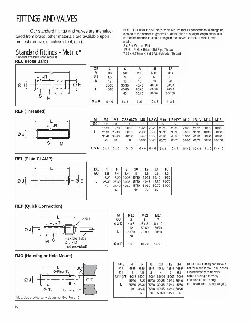
FITTINGS AND VALVES
10
Our standard fittings and valves are manufac-tured from brass; other materials are available uponrequest (bronze, stainless steel, etc.).
S
Ø J
M
RL
Ø J Ø E
L
Standard Fittings - Metric*
REF (Threaded)
REL (Plain CLAMP)
Ø J Ø E
KM
LR
S
REC (Hose Barb)
Flexible TubeØ d x D(not provided)
Ø J
M
R
S
NutL
Ø J Ø T
Ø T1
L 30°
REP (Quick Connection)
RJO (Housing or Hole Mount)
NOTE: CEFIL�AIR® pneumatic seals require that all connections to fittings belocated at the bottom of grooves or at the ends of straight length seals. It isnot recommended to locate fittings in the curved section of radii curvedseals.
NOTE: RJO fitting can have aflat for a set screw. In all casesit is necessary to be very careful during assemblybecause of the O-ring (30° chamfer on sharp edges).
ØEMØJK
L
S x R
4M61.512
30/3540/50
5 x 6
6M8316
30/3540/50
60
6 x 6
8M10
516
40/4550/6070/80
8 x8
10M12
620
40/5060/7080/90
10 x 8
12M14
620
50/6070/8090/100
11 x 8
MØJ
L
S x R
M41.2
15/2025/3035/40
50
3 x 4
M63
15/2025/3035/40
50
5 x 6
M83
15/2025/3035/4050/60
6 x 8
1/8 G5
20/2530/3540/5060/70
8 x 8
M105
20/2530/3540/5060/70
8 x 8
7.65x0.793
20/2530/3540/50
60
6 x 6
1/8 NPT5
20/2530/3540/5060/70
8 x 8
M126
20/2530/3540/5060/70
10 x 8
1/4 G6
20/2530/3540/5060/70
10 x 8
M146
30/3540/4550/6070/80
11 x 8
M168
40/4550/6070/8090/100
13 x 10
ØEØJ
L
41.5
15/2025/30
40
63.4
15/2025/3035/40
50
83.4
20/2530/3540/50
105
25/3035/4045/50
60
126.8
30/3540/4550/60
70
146.8
35/4045/5060/70
80
168.5
45/5060/7080/90
MØJ
d x D
L
S x R
M103
4 x 612
50/6070
8 x 8
M125
6 x 850/6070/80
10 x 6
M147
8 x 1060/7080/90
12 x 8
ØT1
ØTØJ
OringN°
L
44H8
11101815/2025/30
40
66H81.5
1500115/2025/3035/40
50
88H8
21500415/2025/3035/40
50
1010H8
41500620/2530/3540/4550/60
1212H8
51500725/3035/4045/5060/70
S x R = Wrench Flat1/8 G, 1/4 G = British Std Pipe Thread7.65 x 0.79mm = Std SAE Schrader Thread
1414H86.8
1500835/4045/5060/70
80Must also provide cone clearance, See Page 10.
*Imperial available upon request

FITTINGS AND VALVES
NOTES: 1. For REC, REF, REP fittings, and CVL valves, consider the size of
the thread part (M) as of the connection. In case of intermediate value (inch dimensions) take the next larger cone.
2. For demanding uses of silicone CEFIL�AIR® pneumatic seals, we recommend first sandblasting the face surface and then applying an adhesive primer prior to application of adhesive.
hØ nØ m
Housing Fitting and Cone
Ø+
1mm
h+1mm
Standard Sizes*
CEFIL�AIR® molded cones provide maximumbonding between the fittings and the seal itself.
MOLDED CONES
Ø
L
7.65 x 0.79
L = 34 or 50 mm
CVL (SAE Schrader Valve)
32
18 90°
7.65
X 0
.79
7.65 X 0.79
RED (Elbow for CVL)
25
Ø 6
Ø 12
7.65
X 0
.79
REB (Convert CVL or RED to Hose Barb - No Return Valve)
Special FittingsWe can manufacture any type of fitting to meet your specific requirements.
Please contact our technical department.
Standard Valves
11
Ømnh
0.15 (4) 0.15 (4) 0.23 (6) 0.31 (8) 0.39 (10) 0.47 (12) 0.55 (14) 0.62 (16) 0.70 (18)
0.23 (6) 0.31 (8) 0.47 (12) 0.55 (14) 0.82 (21) 0.94 (24) 1.02 (26) 1.10 (28) 1.18 (30)
0.19 (5) 0.23 (6) 0.39 (10) 0.47 (12) 0.55 (14) 0.62 (16) 0.70 (18) 0.78 (20) 0.86 (22)
0.07 (3) 0.15 (4) 0.23 (6) 0.23 (6) 0.39 (10) 0.39 (10) 0.47 (12) 0.47 (12) 0.47 (12)
Ø
* For all other sizes, please contact us.
WARNING:Properties/applications shown throughout this brochure are typical. Your specific appli-cation should not be under taken without independent study and evaluation for suitabili-ty. For specific application recommendations consult Garlock. Failure to select theproper sealing products could result in property damage and/or serious personal injury.Performance data published in this brochure has been developed from field testing, customer field reports and/or in-house testing.While the utmost care has been used in compiling this brochure, we assume noresponsibility for errors. Specifications subject to change without notice. This editioncancels all previous issues. Subject to change without notice.
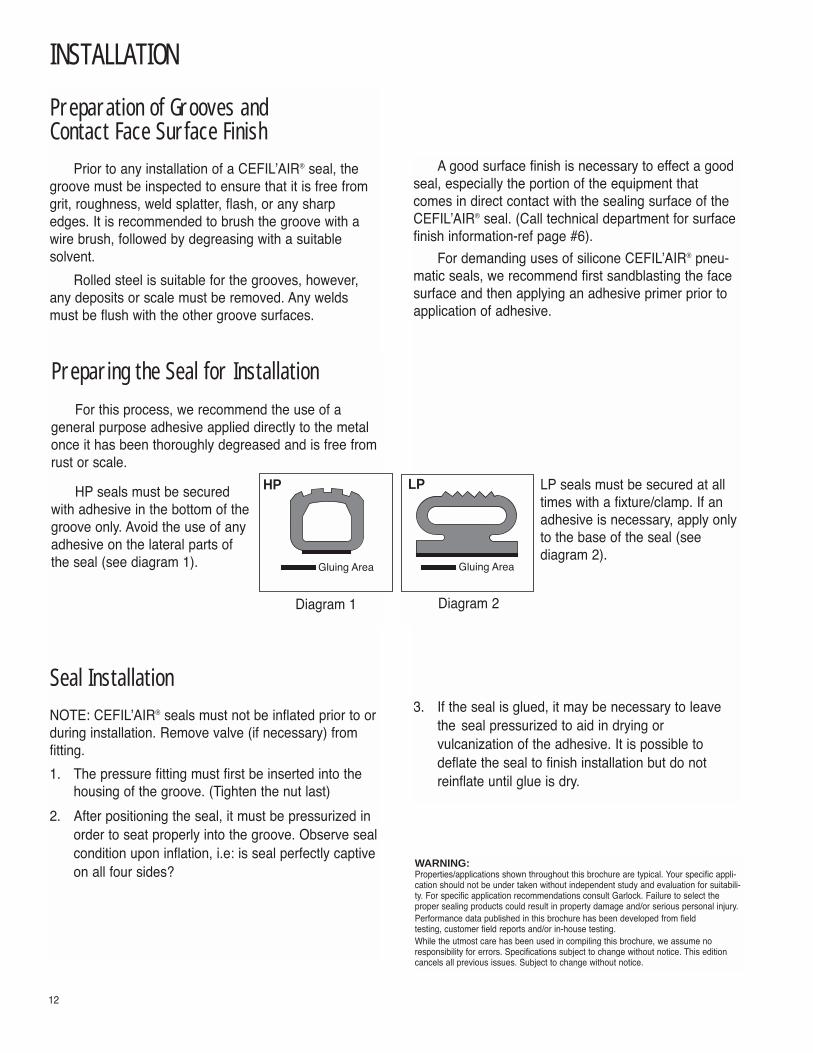
INSTALLATION
12
Preparation of Grooves and Contact Face Surface Finish
Prior to any installation of a CEFIL�AIR® seal, thegroove must be inspected to ensure that it is free fromgrit, roughness, weld splatter, flash, or any sharpedges. It is recommended to brush the groove with awire brush, followed by degreasing with a suitablesolvent.
Rolled steel is suitable for the grooves, however,any deposits or scale must be removed. Any weldsmust be flush with the other groove surfaces.
Seal InstallationNOTE: CEFIL�AIR® seals must not be inflated prior to orduring installation. Remove valve (if necessary) fromfitting.
1. The pressure fitting must first be inserted into the housing of the groove. (Tighten the nut last)
2. After positioning the seal, it must be pressurized in order to seat properly into the groove. Observe sealcondition upon inflation, i.e: is seal perfectly captiveon all four sides?
A good surface finish is necessary to effect a goodseal, especially the portion of the equipment thatcomes in direct contact with the sealing surface of theCEFIL�AIR® seal. (Call technical department for surfacefinish information-ref page #6).
For demanding uses of silicone CEFIL�AIR® pneu-matic seals, we recommend first sandblasting the facesurface and then applying an adhesive primer prior toapplication of adhesive.
3. If the seal is glued, it may be necessary to leave the seal pressurized to aid in drying or vulcanization of the adhesive. It is possible to deflate the seal to finish installation but do not reinflate until glue is dry.
Preparing the Seal for InstallationFor this process, we recommend the use of a
general purpose adhesive applied directly to the metalonce it has been thoroughly degreased and is free fromrust or scale.
HP seals must be securedwith adhesive in the bottom of thegroove only. Avoid the use of anyadhesive on the lateral parts ofthe seal (see diagram 1).
LP seals must be secured at alltimes with a fixture/clamp. If anadhesive is necessary, apply onlyto the base of the seal (seediagram 2).
Gluing Area Gluing Area
HP LP
Diagram 1 Diagram 2
WARNING:Properties/applications shown throughout this brochure are typical. Your specific appli-cation should not be under taken without independent study and evaluation for suitabili-ty. For specific application recommendations consult Garlock. Failure to select theproper sealing products could result in property damage and/or serious personal injury.Performance data published in this brochure has been developed from field testing, customer field reports and/or in-house testing.While the utmost care has been used in compiling this brochure, we assume noresponsibility for errors. Specifications subject to change without notice. This editioncancels all previous issues. Subject to change without notice.

ASSEMBLY CONDITIONS
13
External Pressure at the SealCEFIL�AIR® seals are designed to provide a tight
seal when pressurized. The pressure media (air, water,or a neutral gas) is supplied from an external source.When pressurized, the seal will expand either to the out-side of a pressurized enclosure or towards the inside ofa vacuum enclosure.
A. Pressurized Enclosures
With an internal pressure created by gas or a con-trolled atmosphere, the strength is directly linked to theclearances, deformation of the contact faces and thepressurization of the seal.
In these applications, it is always necessary toreduce dimension �J� to a minimum (see page 6).Minimizing this gap will reduce the risk of radially andaxially installed seals from expanding outward instead ofup toward the face of the equipment.
The external pressure on the seal �PE� is taken asa ratio of 0.7 to 0.8 the internal pressure �Pi� of theCEFIL�AIR® seal, but with limitations established in thetables on pages 6 & 7.
B. Vacuum Enclosures:
It is possible to supply CEFIL�AIR® seals that canwithstand a limited amount of vacuum; please consultour technical department.
Preparing the Pressure Fitting forInstallation
The housing �hole� must correspond to the dimen-sions of the molded conical portion of the fitting of theseal. In the case of threaded fittings (REC, REF, REP,CVL), tightening must be moderate during installation toavoid destroying the elastomer-to-metal bond of the fitting.
Positioning the Pressure FittingCEFIL�AIR® pneumatic seals require that all con-
nections to fittings be located at the bottom of groovesor at the ends of straight length seals. It is not recom-mended to locate fittings in the curved section of radiicurved seals. If an installation requires a lateral pres-sure supply, then elbow fittings or a special construc-tion may be necessary. Please consult our technicaldepartment.
WORKING CONDITIONSInternal Pressure of the Seal
CEFIL�AIR® seals that are not properly installed inequipment must not be subjected to pressures equal toor greater than 12 to 22.5 psi (0.8 to 1.5 bar), depend-ing on the profile.
The maximum pressure applied to the sealdepends on the clearance between the supportingframe and moving panel (see tables on pages 6 & 7).Decreasing the clearance (gap), will allow higherpressures.
WARNING:Properties/applications shown throughout this brochure are typical. Your specific application should not be under taken without independent study and evaluation forsuitability. For specific application recommendations consult Garlock. Failure to selectthe proper sealing products could result in property damage and/or serious personalinjury.Performance data published in this brochure has been developed from field testing, customer field reports and/or in-house testing.While the utmost care has been used in compiling this brochure, we assume noresponsibility for errors. Specifications subject to change without notice. This editioncancels all previous issues. Subject to change without notice.
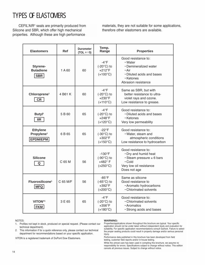
TYPES OF ELASTOMERS
14
CEFIL�AIR® seals are primarily produced from Silicone and SBR, which offer high mechanical properties. Although these are high performance
Temp. Elastomers Ref Range Properties
Good resistance to:-4°F � Water
Styrene- (-20°C) to � Demineralized waterButadiene 1 A 60 60 +212°F � Air
SBR (+100°C) � Diluted acids and bases� Ketones
Abrasion resistance
-4°F Same as SBR, but withChloroprene1 4 B61 K 60 (-20°C) to better resistance to ultra-
CR +230°F violet rays and ozone.(+110°C) Low resistance to grease.
-4°F Good resistance to:Butyl1 5 B 60 65 (-20°C) to � Diluted acids and bases
IIR +248°F � Ketones(+120°C) Very low permeability
Ethylene -22°F Good resistance to:Propylene1 6 B 65 65 (-30°C) to � Water, steam and
EPDM/EPM +302°F atmospheric conditions(+150°C) Low resistance to hydrocarbon
Good resistance to:-130°F � Dry and humid heat
Silicone (-90°C) to � Steam pressure ≤ 6 bars
Q C 65 M 56 +482° F � Cold(+250°C) Very low oil resistance
Does not age
-85°F Same as siliconeFluorosilicone1 C 65 M/F 56 (-65°C) to Good resistance to
MFQ +392°F � Aromatic hydrocarbons(+200°C) � Chlorinated solvents
-4°F Good resistance to:VITON®1 3 E 65 65 (-20°C) to � Chlorinated solvents
FKM +356°F � Aromatics(+180°C) � Strong acids and bases
NOTES: 1. Profiles not kept in stock, produced on special request. (Please contact our
technical department).2. This information if for a quick reference only, please contact our technical
department for recommendations based on your specific application.
VITON is a registered trademark of DuPont Dow Elastomers.
materials, they are not suitable for some applications,therefore other elastomers are available.
Durometer(TOL = + 5)
WARNING:Properties/applications shown throughout this brochure are typical. Your specific application should not be under taken without independent study and evaluation forsuitability. For specific application recommendations consult Garlock. Failure to selectthe proper sealing products could result in property damage and/or serious personalinjury.Performance data published in this brochure has been developed from field testing, customer field reports and/or in-house testing.While the utmost care has been used in compiling this brochure, we assume noresponsibility for errors. Specifications subject to change without notice. This editioncancels all previous issues. Subject to change without notice.

CALCULATIONS AND SUPPLY
Profile No. 512 339 347 356 443 405 627 369 415 639 603 514 529 921 704 736 828 10094 10170
Kj 1.0 1.2 1.2 2.0 2.2 2.3 3.0 3.0 0.7 1.2 1.6 1.6 5.0 0.8 1.5 2.5 3.0 4.2 5.0
Pi 4 4 4 6 6 6 8 8 1 5 6 7 10 3 3 3 3 3 3
Supply of Motive FluidCEFIL�AIR® pneumatic seals can be expanded with
air, neutral gas and also water. However, it is necessaryto provide a constant flow and pressure. All seals must
12
3
4
5
67
3
3
4
4
5
5
5
1 Air Collector
2 Pressure Relief Valve Filter
3 Non-return Valve
4 Pressure Gauge
5 Valve
6 Pressure Switch
7 Warning
If the seals are disconnected from the airsupply source, it is necessary to place ahead loss warning system at the end ofthe seal.
Typical sketch of double cofferdam seal (Standard LP).
be connected to a regulator to avoid overpressurizing(see diagram below).
Application Force CalculationsCEFIL�AIR® seals are retracted even with a residual
internal pressure. The pressure necessary for expansionvaries depending on the application and the profileused.
In the majority of cases, the minimum operatingpressure is 22.5 psi (1.5 bar); this corresponds to anapplication force proportional to a unit of contact surface.
15
Fj = (Pi x Kj) x LD
Pi = Internal pressure of the seal in barsLD = Developed length of the seal in cmKj = Coefficient of unit contact surface
Example of Calculation:
For a CEFIL�AIR® seal with profile number 347, meandiameter 1500 mm used with internal pressure Pi = 2 bars
Fj = (Pi x Kj) x π Ø*= (2 x 1.2) x (3.14 x 150cm) = 1.130 da.N
*Øm = mean diameter of seal(da.N to lb. force mult by 2.248089)
The total applied load �Fj� for the seal on the movingpanel will be determined using the formula:

OTHER PROFILE EXAMPLES
16
2.36 (60.0)
0.98
(25.
0)
1812
2.75 (70.0)1.
29 (3
3.0)
1263
0.70 (18.0)2.
28 (
58.0
)
0.94 (24.0)2104
0.03 (17.5)
0.57
(14.
5)
10266
1.33 (34.0)
0.98
(25.
0)
10410
0.78 (20.0)
0.78
(20.
0)
811
1.18 (30.0)
0.70
(18.
0)
0.62(16.0)
0.62
(16.
0)
1.37 (35.0)
1.37
(35.
0)
1.02 (26.0)
0.78
(20.
0)
0.70 (18.0)
1.06
(27.
0)
2051
372
2190
1406
1856
2239
0.94 (24.0)
0.63
(16.
0)
1381
1.49 (38.0)
1.10
(28.
0)
2578
0.92 (23.5)
0.78
(20.
0)
2017
1.45 (36.8)
0.79
(20.
0)
1132
0.92 (23.5)
0.82
(21.
0)

HELPFUL INFORMATION
17
Cross Section TableStandard European Cross-Section Tolerances forExtruded Seals: (NF T 47001 - December 1971)
Dimensions in Inches (in Millimeters)Above Up To Precision (±) Commercial (±) Non-Critical
(±)
0 0.100 0.010 0.014 0.016
(2.5) (0.25) (0.35) (0.4)
0.100 0.160 0.014 0.016 0.020
(2.5) (4) (0.35) (0.4) (0.5)
0.160 0.250 0.016 0.020 0.028
(4) (6.3) (0.4) (0.5) (0.7)
0.250 0.390 0.020 0.028 0.031
(6.3) (10) (0.5) (0.7) (0.8)
0.390 0.630 0.028 0.031 0.040
(10) (16) (0.7) (0.8) (1)
0.630 0.980 0.031 0.040 0.051
(16) (25) (0.8) (1) (1.3)
0.980 1.570 0.040 0.051 0.063
(25) (40) (1) (1.3) (1.6)
1.570 2.480 0.051 0.063 0.079
(40) (63) (1.3) (1.6) (2)
2.480 3.940 0.063 0.079 0.098
(63) (100) (1.6) (2) (2.5)
WARNING:Properties/applications shown throughout this brochure are typical. Your specific appli-cation should not be under taken without independent study and evaluation for suitabili-ty. For specific application recommendations consult Garlock. Failure to select theproper sealing products could result in property damage and/or serious personal injury.Performance data published in this brochure has been developed from field testing, customer field reports and/or in-house testing.While the utmost care has been used in compiling this brochure, we assume noresponsibility for errors. Specifications subject to change without notice. This editioncancels all previous issues. Subject to change without notice.
(Std for Most Profiles) (Some Large LP Profiles)

An affiliate ofGarlock Sealing Technologies
Date:
Your name:
Sales office:
Date quote required:
e-mail address(es):
Company name:
Rep name:
❑ Qty of seals required (prototype):
Tel: Fax:
Tel: Fax:
❑ Qty of seals required / month:
Application Description:
❑ Sealing ❑ Handling (Lifting, Holding, Pressing, Clamping)
CEFIL�AIR exposed to:
Pressure across seal: psior required force (if handling): lbfPressure media inside seal:❑ Air ❑ Nitrogen ❑ Water ❑ Other:Frequency of inflation: Duration of inflation:
Temperature at the seal: °F
❑ HP ❑ LP ❑ Development ❑ Custom Profile number:
Stock materials: ❑ Q (Silicone) ❑ SBR (Styrene-Butadiene)
Non-stock materials: ❑ CR (Chloroprene) ❑ IIR (Butyl)❑ EPDM/EPM ❑ MFQ (Fluorosilicone) ❑ FKM (Viton®)
Shape: ❑ Circular Seal ❑ Rectangular Seal ❑ Combination (Call to explain)Expansion: ❑ Axial ❑ Internal Radial ❑ External RadialSee Dimension Picture (next pages) and enter data from Catalog for new applications OR your existing seal/available area.HP in a groove shown � LP may be foot-mounted. If profile is selected, verify the minimum radius from the Catalog.
Straight Length SealSee Dimension Picture & enter data from Catalog for new applications OR your existing seal / available area.Note: SL = length to be sealed or available length to handle (lifting, holding, pressing, clamping)❑ Retracted end (Standard)❑ Expanded end (See Catalog for description; call for details on HP profiles)❑ Expandable end (See Catalog for description; call for details)❑ Fitting in the end plug (Note: Molded Cone shown below is not required)❑ Fitting in the foot (Enter distance required to fitting or valve on the Dimension Picture)
Fitting: ❑ REC ❑ REF ❑ REL ❑ REP ❑ RJO Diameter: Length:
Valve: ❑ CVL, Length ❑ 34mm ❑ 50mm Optional for CVL valve: ❑ RED elbow ❑ REB conversion to hose barb
Material: ❑ Brass (standard) ❑ Stainless steel ❑ Other
Cone: The housing must accept the cone. If you choose a RJO Comments:fitting, the equipment must also have a chamfer to avoid tearingthe o-ring.
Sketch: (Also attach equipment drawing and/or pictureof application if possible.)
GarlockSealing Technologies®
CEFIL�AIR DATA SHEET®An affiliate ofGarlock Sealing Technologies
Housing
h+1mm =
h =
Fitting and Cone
Ø
Ø n =
Ø m =
Ø+1mm =

An affiliate ofGarlock Sealing Technologies
19
GarlockSealing Technologies® CEFIL�AIR Dimension Picture®
Circular Seal, Internal Radial
Circular Seal, External Radial
Circular Seal, Axial

20
GarlockSealing Technologies® CEFIL�AIR DIMENSION PICTURE®
Rectangular Seal, Internal Radial
Rectangular Seal, External Radial
Rectangular Seal, Axial
An affiliate ofGarlock Sealing Technologies
W=
GarlockSealing Technologies® CEFIL�AIR DIMENSION PICTURE®
21
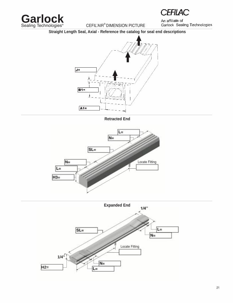
1/4”
H2=
Locate Fitting
Locate Fitting
Retracted End
Expanded End
Straight Length Seal, Axial - Reference the catalog for seal end descriptions

PRINTED IN U.S.A. CF5:1 GPS-1/04-REV-B-500
AUTHORIZED DISTRIBUTORWARNING:Properties/applications shown throughout this brochure are typical. Yourspecific application should not be undertaken without independent studyand evaluation for suitability. For specific application recommendationsconsult Garlock. Failure to select the proper sealing products couldresult in property damage and/or serious personal injury.Performance data published in this brochure has been developed fromfield testing, customer field reports and/or in-house testing.While the utmost care has been used in compiling this brochure, weassume no responsibility for errors. Specifications subject to changewithout notice. This edition cancels all previous issues. Subject tochange without notice.GARLOCK is a registered trademark for packings, seals, gaskets, andother products of Garlock.© Garlock Inc 2004. All rights reserved worldwide.