ceramic grinding temperatures
TRANSCRIPT

8/2/2019 Ceramic Grinding Temperatures
http://slidepdf.com/reader/full/ceramic-grinding-temperatures 1/7
Ceramic Grinding Temperatures
Rajadasa R. Hebbar,* Srinivasan Chandrasekdr,* and Thomas N. Fdrris*
School of Industrial Engineering and School o f Aeronautics and Astronautics, Purdu e IJniversity,Wcst Lddyette, Indiana 47907
Workpiece and abrasive-tip temperatures are measuredduring the grinding of silicon nitride, zirconia, sapphire,and Ni-Zn ferrite with diamond abrasives. The measure-ments are carried out using a multiple-element infraredsensor having a time constant of -7 ps and a spot size assmall as 30 pm in diameter; the temperature measure-ments were made for both single-point and full-wheelgrinding. A simple analytical model is used to predict theabrasive-tip and work-surface temperatures, the subsur-face temperature of th e workpiece, and the cooling of theabrasive grains between cutting. The predictions of themodel agree reasonably well with experiments. The model
requires as inputs only the grinding forces, grinding pro-cess variables, and the ph ysical properties of th e abrasiveand workpiece materials. It is shown that, in view of theexcellent thermal properties of the diamond abrasive, thesurface temperature of the ceramic workpieces is essen-tially independent of the thermal properties of theceramics.
I. Introduction
H E machining of ceramic materials is commonly accom-T l ished by grinding with diamo nd abrasive wheels. Duringgrinding, high temperatures are generated at the interfacebetween the wheel and the workpiece as well as i n the worksubsurface, due to frictional heating and localized plastic
deformation. T he high temperatures are an important source ofdamage on the machined surface. I-' Firstly, the transienttemperatures generated by grinding contribute to residualstresses and microcracking on the ground surface. Secondly,the localized temperatures cause warping of the component,especially when it is of small size and has a large surface-to-volume ratio. Thirdly, they can induce phase transformationson the ceram ic surface. Such phase transform ations occur, forexample, during the localized heating of magnetic ceramicssuch as ferrites above the Curie temp erature4 and th e grindingof transformation-toughened zirconia. In the latter case, thephase transformations are a consequence of th e transient ther-mal and mechanical stresses produced by grinding. Grinding-induced damag e alters the mechan ical, magn etic, and electricalproperties of the ground ceramic. Furthermore, the transient
temperatures prevailing at the ab rasive grain tip d uring grind-ing contribute to wheel wear. Wheel wear can occur by ther-mally induced degradation of the bond holding the diamondabrasives together on the wheel, by graphitization of the dia-mond particles when heated above 1200°C n air,' by microfrac-ture of th e abrasive grain as a consequence of repeated heating
R . 0. Scartcrgood~conlributiiigditor
Manuscript No 196144. Receivcd D ecembcrS , 1 99l , approvcd June I I, 092.'This work wa h partially hupportcd by thc N ational Science Foundation (NSF)
through Grant Nos DD M 90579 6 Prograni in Manufacturing Proccrses an d S y s -terns, Dr. B Krdrncr, Director) and MSS 9057082 (Surface Engincering and Tri-bology Program. Dr. J . Larsen-Basse, Director)
*Member, Anicrican Ccrarnic Socicty.;School or Induhtrial Engineering .'School 0 1 Aeronautics and Astro nautics.
and cooling, o r by diffusion wear of diamond at high tempera-tures when grinding ferrous materials. ' Therm al phenom enathus play a key role in the mechanics of the grinding process.The measurement of peak temperatures generated during thegrinding process is critical to an understanding and predictionof the various phenomena occurring in the wheel and work-piece and in the d evelopment of analytical models for ceramicgrinding temperatures and stresses. Of course , control of thesetemperatures would be valuable in the production grinding ofceramic components .
11. Background
Th e diamond particles in grinding wheels used in ceramicgrinding are typically 20-200 p m in size and irregularlyshaped. They also cool rapidly after they leave the grindingzone. Therefore, the high temperatures generated at the dia-mond particle tip exist over small areas and for periods of timeof the order of 3 0 4 0 ps. Any sensor for measuring the peaktemperature must therefore be able to sam ple hot spots as smallas 20 p m in diameter and have a time constant - 10ps or less.In the past, thermocouples have been embedded at variousdepths in the w orkpiece to measure the workpiece temperature.Such thermocoup le prob es have a poor frequency response andspatial resolution an d therefore cannot accurately estim ate thepeak grinding temperatures .*
Mayer and Shaw' were the first to obtain th e temperature of a
freshly ground steel surface by measuring the infrared (IR)radiation emitted from it using a lead sulfide detector. LaterKops and Shawl" photographed the radiation emitted by thewheel and the chips on an 1R-sensitive film to qualitatively
study the grinding temp erature distribution around the wheel.Ueda et al." used an infrared sensor with a n indium antimonide
(InSb) detector to m easure the wheel-surface and work-subsur-
face temperatures during the grinding of steel. All the above IRgrinding temperature measurements were obtained during the
grinding of steels. Furthermore, the techniques assumed thatthe target was either a black body with an emissivity of 1 o r agray body (constant emissiv ity) with an emissivity value which
was directly measured by a calibration procedure. While thegray body assum ption is reasonable at a given temperature overa small range of wavelengths, the use of directly measuredemissivity values in the temperature measurement procedurecan lead to considerable error in the measured temperature. ''This is because th e target emissivity during grinding could bequite different from its value during the calibration experi-men ts. For exam ple, if the infrared sensor was focused on th eabrasiv e part icle, the particle's emissiv ity would be influencedby any chip fragments adhering to it . Hence the use of anappropriate emissivity com pensation algorithm which does notrequire a direct measurement of the target emissivity is desir-able for accurate IR temperature measurements.
Grinding temperatures were measured during the grinding ofelectronic ceramics such as Ni-Zn ferrite and sapphire by Chan-drasekar et ~ 1 . ' ~nd Farris and Cha ndr asek aP us ing a mult iple-
element infrared sensor. The sensor used a fiber-optic lens
assembly to pick up the radiation from the target (diamondabrasive) and focus i t on the detector plane. The sensor had a
2142

8/2/2019 Ceramic Grinding Temperatures
http://slidepdf.com/reader/full/ceramic-grinding-temperatures 2/7
spot size of 40 pin diameter and a time constant of 6.8 p s . Adirect calibration procedure w as, however, needed to comp en-sate for the emissivity. The temperature measurements wereconducted during single-point grinding, i .e., grinding with asingle-diamond indenter mounted on th e periphery of an alumi-num w heel, and for grinding with a complete resin-bonded dia-mond wheel. The target, being the abrasive particle(s) on thewheel, was observed through a hole in the ceramic workpiecejust after it completed the grinding ac tion.
The prescnt study describes experimental measurements ofthe abrasive and workpiece temperatures during the dry grind-ing of structur al ceramics-tetragonal zircon ia poly crystal(TZP) and hot-pressed silicon nitride-and, for comp arison,electron ic ceramics-Ni-Zn ferrite and sapph ire. A modifiedversion of the multiple-element infrared sensor used by Chan-drasekar et ui.” was used to carry o ut these measurements . Themodifications enable emissivity com pensation to be conductedusing a multiwavelength technique which did not require adirect measurement of target emissivity. Furtherm ore, the sen-sor optics were improved to enable a m inimum spot size of 30-p m diameter to be sampled by the sensor. No temperature mea-surem ents were carried out during wet grindin g, as the scatter-ing of the infrared radiation by t he coo lant would lead to con-siderable coniplicationr while interpreting the measurements.
An analytical model based on th e work of Sh awl5 was used tocalculate the abrasive-t ip temperature a nd th e workp iece sub-surface temperature, and the predicted values are comparedwith the experimentally measured temperatures. The conse-quences of such localized temperatures in the ceramic work-piece and diamond indenter are discussed.
emitted light was measured over a narrow band o f wavelengthccntered at O.Y, 1 . I , an d 1.3 pm, and the temperature wasdetermined by comparison with black-body radiation. Thewidth of the wavelength band was 0.2 p m , i.e., ? 0.1 p mabout each of these three wavelengths. For this purpose a spe-cial spectrometer was constructed using the InSb detectorswhich could simultaneously detect weak radiation signals atthree different wavelengths. The experimental configurationfor doing this is shown in Fig. 1 . Th e light emitted from the tar-get w as collected by a flexible fiber-optic lens assembly, fromwhich a beam divider with filters selects a narrow beam ( 2 0 .
pm) of radiat ion centered around the three wavelengths ofinterest. The beams impinged on the cooled detectors, and theoutput of the detectors was amplified and recorded in a digitalstorage oscilloscope.
Th e radiation emitted by a heated target at temperature T is a
function of wavelength and is given by Planck’s Law as
where E , is the monochromatic emissive power at wavelengthA , C , an d C2 re constants, and F ~ , ?s the emissivity of t he tar-get at temperature T and wavelength A. If the target is a blackbody, then E , , ~= I . The pow er radiated over a narrow band of
wavelength (Ax) centered at A is obtained by integrating E ,over this range as
111. Experimental Procedure
The multiple-element infrared sensor used in the experi-ments consisted of eight indium antimonide (InSb) detectors(Santa Barbara Research Corporation and Barnes Corpo ration)and a high-speed thermal monitor (Vanzetti Systems Corpora-tion). Th e detectors were mounted o n a Dewar flask which wascooled by liquid nitrogen to a temperature of 77 K . Indium anti-
monide responds to radiation in the 0.65-5.3 -pm range andcan be conveniently used in the photovoltaic mode to giveresponse times as low as I p s . When cooled with liquid nitro-gen, the performance of indium antimonide improves signifi-cantly, d ue to lower thermal n oise and also longer wavelengthsensitivity. The detector elements were coupled to fiber-opticlens assemblies which transmitted th e radiation from the sou rceto the detector plane. With the multiple-element sensor, tem-perature measurements could be made simultaneously at fourdifferent locations. The sm allest spot size achievable with thepresent arrangement was 30 pm; that is , the detector couldsense “hot spots” of 30- pm diameter .
The detectors were calibrated statically and dynamically.Static calibration was performed by exposing it to a standardinfrared source. Dynamic calibration was performed as
follows:( I ) A came ra shutter was placed between a standard (refer-
ence) infrared source and th e detector. T he shu tter opening wascontrolled to expose th e source for periods as short as 100ps.
The detector was exposed to a s tandard (reference)infrared source through a hole near the periphery of a spinningaluminum d isk. This configuration is similar to that of the high-speed grinding experiment.
Th e t ime constants of the detector elements were determinedas the time taken for the response to reach 63% of the final
valuc for a step temperature input. Each detector element wascalibrated separately, and the responses of the InSb elementswere qualitatively similar to each other. The time constant of
the s lowest InSb element was 6 .8 ks, while the Vanzetti h igh-speed detector had a tim e constant of 7.4 p s .
Typically, infrared temper ature sensin g is carried o ut by mea-suring the radiative power emitted by the target over a range ofwavelengths. In ou r measurements, the radiative power of the
(2 )
where K is a constant dependent on t he geo metric radiation col-lection and transmission characteristics of the fiber-optic lensassembly system. Typically exp(C,/AT) >> I . Therefore,
In the present experiments, since the radiative power valueswere measured around three closely spaced wavelengths,
can be assumed constant over this range of wavelengths. Thisassumption enables the temperature to be determined from thepower measu rements without explicitly determining th e emis-sivity. The radiative power values measured in the three wave-length windows were normalized by dividing by the powervalue around the wavelength of A = 0.9 p m . The normal izedpower values were then compared with the normalized black-body radiation spectrum to obtain the temp erature of the target.This technique a nd its variants have been used by oth er investi-gators, notably Weichert and Sch onert“ to obtain the tempera-ture rise ahead of a propagating crack and Gulino et u1.” to
measure the temperature rise at asperity contacts. The tech-nique has the advantage that, by making radiative power mea-surements at three closely spaced wavelengths and taking thenormalized power values, emissivity compensation is achieved
to a first order without making a direct measurem ent of the tar-get emissivity.
IV. Results
(1 ) Single-Point Grinding Temperatures
Figure 1 is a schematic of the experimental arrangementused in the temperature measurement studies. A conical dia-mond indenter with a 90”apex angle and with a hemispherical
t ip of radius - 5 p m w as mounted on the periphery of an alu-minum disk and slid against the ceramic work surface. Th e rel-ative sliding velocities between the indenter and the ceramic
varied betw een 25 and 37 m/s, which are surface speeds com-monly encountered in surface grinding. The multiple-element
infrared sensor monitored the radiation from the diamondindenter tip just after i t ground and passed across the 2-mm-diameter hole in the w orkpiece. At a disk peripheral velocity of

8/2/2019 Ceramic Grinding Temperatures
http://slidepdf.com/reader/full/ceramic-grinding-temperatures 3/7
2744 Journcrl of th e Arnericun Cerurnic Society-Hebbur et u l .
Fig. 1. Schematicof the m easurement system for grinding temperatures
35 mis, the fiber-optic lens assembly was exposed to radiationfrom the diamond tip for approximately 20 p s , which is about 3
t imes th e time constant of the lnSb detcctors. Thus it was pos-sible to obtain a direct measurement of the diamond-tiptemperature.
Four different ceramics-tetragonal zirconia polycry stal
(TZ P), hot-pressed silicon nitride (Si,N,), single-crystal alu mi-num oxide (sapphire), and polycrystalline Ni-Zn ferrite-wereused as workpiece materials. The ceramic workpieces wereplate specimens -43.75 mm long X 12.5 mm wide X 5 mmthick with the surface to be ground being of rectangular crosssection (-43.75 m m X 12.5 mm). In the case of sapphire, thee-axis was oriented perpendicular to the surface being groun d.The mechanical and thermal properties of the ceramics are
given in Table I .
Table 1. Propertiesof Work Materials andDiamond Abrasive*
Zirconia(YZ-1101' Si,N, SaoDhirc Ferrite 1070 Steel Diamond
E (Gpd) 210 300 390 191 203 1000
1, 0.24 0 26 0 23 0.2 0.26 0.2
k(W/(m."C)) 2.2 33 35 8.7 47 1000
c(J / (g."C)) 0.63 0.72 0.95 0.71 0.432 0.525
P W m ' ) 6.1 3.22 3.90 5.3 7.84 3. 5
kp c ' 8.45 76.5 129.7 32.7 159.2 1837.5
H (GPa) 12 16.7 19.6 7.3 88
* E is Youngs modulus. Y ih the Poissonratio, i s thermal conductivity, c is specilichut . 11 i:, mash dcnsity, and H S hardness. 'YZ- 10 is a tctragonal zi rcmia polycrystdmanutacturcd hy Norton Company. 'The value:, listed arc the product of I , . and ('
tahulatcd ahovc
Table 11. Single-Point Grinding Temperatures*~~
Ternperdure ("C)
V = 2 5 mi \ V = 1 2 m / \ V 17 m/ a
Malcri.il h" b' A' t A' E A'~ ~~ ~
Zirconla 0064 1260i51 1320 l60I+74 1494
S I , N , 0 17 1133-60 1 I I0 14.52?49 12.55
bcrritc 0 12 570 230 480 620?35 542 69 0t 30 583
Smnhirc 0 2 I 920i 5 1060& 45 1270tX0
18oo.r
1500.
Vol. 75, No. 10
0
0
0
0
1 I I I 1 I I
1 2 3 4 5 6 7 0Event
Fig. 2. Distribution of measured temperatures in the single-pointgrinding of zirconia in which the ex perimental conditions for the eight
measurements were identical (depth o fcu t,10pn;
able velocity,23.4
mni/s; wheel velocity, 32 ids; diamond t ip radius, 15 km).
1400.L
Table I1 shows th e measured values of the diamond-tip tem-perature during the single-point grinding of the ceram ic materi-als. The measurements were made by observing the diamondtip through a hole in the workpiece. The depth of cut used inthe experiments was 10 p m , and th e table velocity was 23.4
m d s . The va lues reported in Table I1 are the average and thestandard deviation of measurements made from 6 to 10 nomi-nally identical contacts. Because of local variations in thenature of each co ntact, the temperature of the diamond tip var-ies from on e contact to anothe r even though th e grinding condi-tions are the same; a typical measured distribution of thediamond-t ip temperature over eight nominally identical co n-
tacts is shown in Fig. 2 for the grinding of tetragonai zirconiapolycrystal (TZP).
The experimentally measured temperature of the diamondgrain in Table I1 increases with increasing sliding velocitybetween the tip and t he ceramic surface. The highest tempera-tures were reached during th e grinding of zirconia, followed inorder by silicon nitride, sapphire, and nickel zinc ferrite. Asnoted in the Introduction, graphitization of diamond in air hassometimes been observed to occur at a temperature of- 200"C, and this tem perature is exceeded in th e present studyduring th e single-point grinding of zirconia, silicon nitride, andsapphire. However, it should be pointed out that the graphitiza-tion referred to occurred when millimeter-sized diamond crys-tals were heated in air for extend ed times.'
(2) Decay of Abrasive-Tip Temperature
In order to measure the decay of the diamond-tip tempera-ture after it grinds and leaves the workpiece, fiber-optic pickupprobes were mounted at 90" intervals along the arc of rotation
8/2/2019 Ceramic Grinding Temperatures
http://slidepdf.com/reader/full/ceramic-grinding-temperatures 4/7
2745
2ooo1
8 00Ek-
0 .
S
0. 5. 10. 15. 20.Time (milliseconds)
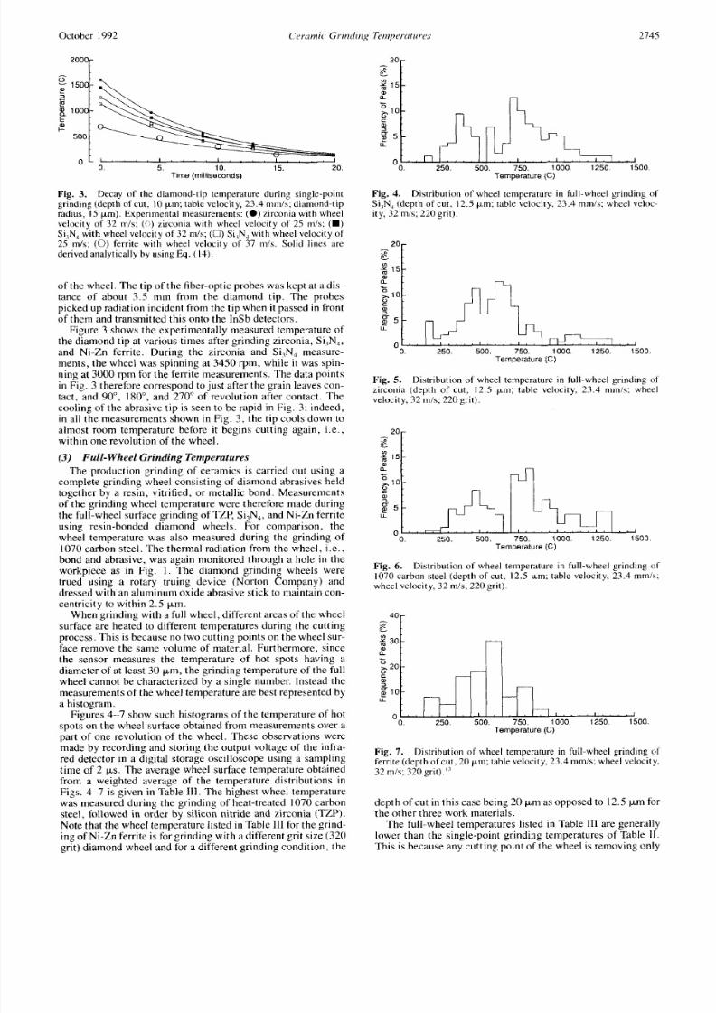
Fig. 3. Decay of the diamond-tip temperature during single-pointgrinding (depth of cut, 10pm; able velocity, 23. 4 mmis ; diamond-tipradius, I5 pm). Experimental measurements: ( 0 ) irconia with wheelvelocity of 32 m/s; (0)irconia with wheel velocity of 25 m/s; (W )
Si,N, with wheel velocity of 32 m/s; (0)i,N, with wheel velocity of25 m/s; (0 ) errite with wheel velocity of 37 mis. Solid lines arederived analytically by using E q. (1 4).
of the wheel. The tip of th e fiber-optic probes was kept at a dis-tance of about 3. 5 mm from the diamond t ip . The probespicked up radiatio n incident from the t ip when it passed in frontof them and transmitted this on to the lnS b detectors.
Figure 3 shows the experimentally measured temperature ofthe diamond tip at various times after grinding zirconia, Si,N,,and Ni-Zn ferrite. During the zirconia and Si,N, measu re-ments, t he wheel was spinning at 3450 rpm, while it was spin-ning at 3000 rpm for the ferrite measureme nts. The data pointsin Fig. 3 therefore correspond to just after the grain leaves con-tact, and 90", 180", and 270" of revolution after contact. Thecooling of the abrasive tip is seen to be rapid in Fig. 3; indeed,in all the m easurements shown in Fig. 3, the tip cools down toalmost room temperature before it begins cutting again, i.e.,within one revolution of the w heel.
(3) Full-Wheel Grinding Temperatures
The production grinding of ceramics is carried out using acomplete grinding wheel consisting of diamond abrasives held
together by a resin, vitrified, or metallic bond. Measurementsof the grinding wheel tem perature were therefore made duringthe full-whe el surface grinding of TZP, Si3N,, and Ni-Zn ferriteusing resin-bonded diamond wheels. For comparison, thewheel temperature was also measured during the grinding of
1070 carbon steel. Th e thermal radiation from the wheel, i. e.,bond and abrasive, was again monitored through a hole in theworkpiece as in Fig. I . The diamond grinding wheels weretrued using a rotary truing device (Norton Company) anddressed with an aluminum oxide abrasive stick to maintain con -centricity to within 2.5 p.m.
Whe n grinding with a full wheel, different areas of the wheelsurface are heated to different temperatures during the cuttingprocess. This is because no two cutting points on the wheel sur-face remove the same volume of material. Furthermore, since
the sensor measures the temperature of hot spots having adiame ter of at least 30 p m , the gr inding temperature of the ful lwheel cannot be characterized by a single number. Instead themeasu rements of the wheel tem perature are best represented bya histogram.
Figures 4-7 show such histograms of the temperature of hotspots on the wheel surface obtained from measurements over apart of one revolution of the wheel. These observations weremade by recording and storing the output voltage of the infra-red detector in a digital storage oscilloscope using a samplingtime of 2 p s . The average wheel surface temperature obtainedfrom a weighted average of the temperature distributions inFigs . 4-7 is give n in Table 111. The highest wheel temperaturewas measured during the grinding of heat-treated 1070 carbonsteel, followed in order by silicon nitride and zirconia (TZP).
Note that th e wheel temp erature listed in Table 111for the grind-ing of Ni-Zn ferrite is for grinding with a different grit size (320grit) diamond wheel and for a different grinding condition, the
f 1 5 1
a
g 5i. 250. 500. 750. 1000. 1250. 1500
OO.
Temperature (C )
Fig. 4. Distribution of wheel temperature in full-wheel grinding o fSi,N, (depth of cut , 12.5 pm; able velocity, 23.4 mmis ; wheel veloc-ity, 32 m/s; 22 0 grit).
250. 500. 750. 1000. 1250. 1500Temperature (C)
Fig. 5. Distribution of wheel temperature in full-wheel grinding ofzirconia (depth of cut, 12.5 p m ; table velocity, 23.4 m m i s ; wheelvelocity, 32 mis;220 grit).
750. 1000. 1250. 1500Temperature (C )
Fig. 6. Distribution of wheel temperature in full-wheel grinding of1070carbon steel (depth of cut, 12.5 pm; able velocity, 23.4 mm/s ;wheel velocity, 32 mis; 220 grit).
1"12 0
a
g 10;i1
0 ~ ~ ~ ~ ~ ' ~ ~ " ' ~ ~. 250. 500. 750. 1000. 1250. 1500Temperature (C )
Fig. 7. Distribution of wheel temperature in full-wheel grinding o lferrite (depth of cu t, 20 pm ; table velocity, 23.4 mm/s; wheel velocity,32 mis; 320 grit)."
depth of cut in this case being 20 p m as opposed to 12.5 p m forthe oth er three work materials.
The full-wheel temperatures listed in Table 111 are generallylower than the single-point grinding temperatures of Table 11.This is because any cutting point of the wheel is removing only

8/2/2019 Ceramic Grinding Temperatures
http://slidepdf.com/reader/full/ceramic-grinding-temperatures 5/7
2746 .lorirritil 01 th e American Ceramic Society-Hehhur pt a l .
- a
Vol. 75, No . 10
Table Ill . Average Wheel Surface Temperature inFull-W heel Grinding*
Matcrial 'li.inpcraturc ("C)
Si,N, 692
Zirconia 592
Steel 72Ferrite 620
* 2 2 0 grit SILC dianiond whecl. 32 inA surlacc velocity. 12.5-pni depth 01 cu tb r Si,N,. Lirconia . and sfeel: 320 grit SILC i i i i i i ~ i i dwheel ;ind 2O-pin depth of cu flo r Icrrtte.
a fraction of the material removed by the diamond indenter insingle-point grinding.
(4 ) Subsurface W orkpiece Temperatures
Small blind holes, approximately 700 kin in diameter andextending to variotts depths below the surface bcing ground,were drilled from th e back side of thc Si,N,, ferrite, and steelworkpieces. The holes were polished with a diamo nd paste to
make the wall surfaces smooth. Fiber-optic pickups wereembedded in the hole to pick up the thermal radiation from th ebottom face of th e blind hole as the grinding wheel approachedthe holc. T he peak temperature signal was recorded during th isapproach. Thc purpose was t o measure the temperature at dif-
ferent points in the subsurface of the workpiece and therebyobtain the temp erature gradient in the workpiece during grind-ing with a full diamond wheel.
Figure 8 shows the measured temp erature at various points inthe subsurface of the ceramic and steel workpieces. Th ese areaverages from five similar experiments. The depth below thesurface is the distance below the freshly ground surface. Thetemperature gradients near the surface in Fig. 8 are the highesti n Ni-Zn fe rrite and lcss so in the case of Si,N, an d 1070 carbonsteel. In fact, t t 'c gradients near the surface are about the sa mein Si,N, and 1070 carbon steel. No subsurface temperaturemeasurements were carried out in zirconia and sapphire, as itwas very difficult to drill clean blind holes i n these m aterials. Itshould be pointed o u t that no corrections were made i n th emeasurements for the infrared radiation entering the fiber-optic
lens assembly from the lateral faces of the hole. Th e measuredvalues of the sub surface temperature are therefore somewhat ofan overestimation of the true subsurface temperature.
V. Analysis
We describe a simple modcl to analytically estimate theabrasive-tip temperature ( = surface tem perature of workpiece)from a knowledg e of the material properties of the abrasive andworkpiece, and a measurement of grinding forces. From thistemperature, both th c subsurface temperature of the workpieceand the decay of the abrasive tip temp erature after grinding arcalso approximately calculated.
00Or
400
+-
200
0.
01;10 15 20 25 30- -5 4 0
Depth Below Sufiace microns)
Fig. 8. Subsurfacc workpiece temperature during full-wheel grind-ing. Table velocity, 2 3.4 m m A and wheel velocity, 32 m/s. ( ( 0 )errite(mcasured. 320 grit, 20-pm depth o f cut);(0)i,N, (measured,220grit, 12.5-pm depth of cut) : (0)070 steel (measured, 22 0 grit.
12.5-pm depth of cu t ) . ) The solid lines ar e calculated values fo r th esubsurface temperature, obtained by matching the experimentallymeaaured tcmp cratures at the surface (aee text fo r description).
Fig. 9.
perature calculations.Schematicof the moving heat source model used in the tem-
( I ) Single-Point Grin ding Temperatures
Chandrasekar et 01 . I' showed that a moving heat sourcemod el'x could be used to accurately calculate the abrasive-tiptemperature and the surface temperature of the workpiece insinglc-point grinding. We briefly describe this analysis andapply it to an alytically estimate the single-point grinding tem-
peratures which were measured in this study.Figure 9 shows the schematic of the moving heat sourcemodel used in th e calculations. Th e moving heat source modelapproximates the workpiece as a semiinfinite solid whoseboundary is insulated away from the heat source. The heatsource has a length of 20 in the sliding direction and is of infi-
nite extent perpendicular to the sliding direction. It is movingacross the solid with a velocity V and is assumed to generateheat at a rate o f 4 pe r uni t area per unit time (Fig. 9). The solu-t ion of the temp erature distribution for this problem involvesmodified Bessel functions. If the Peclet number
2vuL = - - - > 2 0
cy(3)
wherecy =
k/(pc) is the thermal d iffusivity of the solid, thenthe flow of heat parallel to the surface can be neglected withrespect to the veloci ty of th e mov ing heat source. This approxi-ination is appropriate for the single-point grinding experimentswhere the ab rasive grain is moving with a velocity of 30 mis.
The differential equation and the boundary conditions gov-erning the one-dimensional transient temperature distributionar e
lim T + 0I i l
T(z,O) = 0 (4)
where T = T ( z , t ) s the temperature of the workpiece at depthz Fig. 9 ) , t is time, and R is the fraction of the generated heatthat flows into the workpiece. The solution to this boundaryvalue problem is (Section 2.9 of Cars law and Jae ge P)
( 5 )
where erfc is the com plementary error function . On the surface

8/2/2019 Ceramic Grinding Temperatures
http://slidepdf.com/reader/full/ceramic-grinding-temperatures 6/7
October 1992 Ceramic, Grinding Tcmnpcratitues 2747
Assuming that at a particular point on the surface the heat isapplied beginning at x = - a , the t ime of heating for a point onthe surface is t = ( a - x ) /V , and th e temperature at a point on
the surface is
/a(u -x)
d=
The average surface temperature is
(7)
which form is consistent with that of a similar analysis given byRam anath and Shawl' for full-wheel grinding.
Equations (4) an d (7) can be written for the abrasive grain aswell as the work piece if R is replaced by 1 - R and the proper-ties of the abrasive are used. W riting such an equation and set-ting the average temperature of the grain equal to the averagetemperature of the workpiece under condition s of thermal equi-librium gives'"
1R =
1 +Jgwhere the subscripts A and W refer to the abras ive and the
workpiece, respectively.Th e concentrated contact between the abrasive and the work-
piece is very similar to that observed in a microhardness test. If
we assume that the contact is a circular patch of radius a , th e
radius of contact can be ob tained as
u = & (9)
where N is the normal grinding force and H is the Vickers hard-
ness of the workp iece. Th e heat generated per unit area per unit
t ime is
FVq = s
where F is the tangential grinding force. Note that this modelof the moving heat source does not require any knowledge ofthe fundamental deformation mechanism (such as brittle frac-ture, plastic deformation, or plowing) leading to heat genera-t ion. Subs ti tu t ing E q . (3) and (8-10) in Eq. ( 7 ) , the averagesurface temperature (Tdvg)f the workp iece and the grain in sin-gle-point grinding is obtained as
When [ (kpc), l (kpc),] >> 1, Eq . ( 1 1) becomes
- 8 f l F ITdVP -
3 n Jz ?'?Jman d T,, is independent of the thermal properties of the work
material. Equations ( 1 1 ) or (12)along with Eqs . (9) an d (10)can now be used to calculate TdvBf the normal and tangentialgrinding forces are known. In our analysis, these grindingforces were measured and used as inputs .
When grinding with a single-point diamond indentermounted on the periphery of an aluminum disk, th e indenter isin contact with the ceram ic workpiece for only a short period of
time (-50 ps or less) . A dynamom eter with a high natural fre-quency is therefore required to measure the single-point grind-ing forces. In the present study, normal and tangential forces
Table IV. Sinele-Point Grinding Forces*
Material
Normal force
( N )
Tmgi'ntial
forceIN 1
Zirconia 2.0Si,N, 4.5Ferritc 0.7
0.700.95
0.20
*Dcpth of cut. 10pm; dh k vclocity, 23 4 mmis;wheel velocity. 32 mls forrirco-nia an d Si,N, and 37 m/b hf cr ri tc ; diamond-tip radius, I S pm.
were measured by mounting the ceram ic workpieces on a two-component piezoelectric force sensor (Kistler Corporation).The sensor consisted of two quartz piezoelectric crystals, oneto measure the normal force and the othe r to measure the fr ic-tional or tangential force. A charge amplifier was used to condi-tion and amplify the piezoelectric crystal outputs. The outputof the charge amplifier was recorded on a digital storage oscil-loscope. The natural frequency of the force sensor was -30kHz in the tangential direction and -60 kHz in the normaldirection, which was sufficiently high for both of the compo-nents of th e single grain force to be measured.
Forces were measured during t he grinding of zirconia, Si,N,,and Ni-Zn ferrite. Table IV gives the average values of themeasured forces in the normal and tangential directions. The se
were used in Eq. ( 1 1 ) to estimate the single-point grindingtemperatures.
Table II gives the analytically estimated temperaturesobtained from Eq . ( 1 1) and values of R (Eq. (8)) or the single-point grinding of zirconia, silicon nitride, and ferrite. Thepredictions agree reasonably well with th e experimentally mea-sured temperatures (also listed in Table 11) both in magnitudeand in their variation with increasing wheel velocity. Eventhough the single-point grinding process is inherently three-dimensional , the reasonably good predict ions of the measuredtemperature with our two-dimensional model suggest that thismodel is sufficiently accurate for estimating the grindingtemperature.
(2 ) Single-Point Grain Coolin g
To a first order, the cooling of the grain in air after cuttingmay be mod eled as a lumped system cooled by forced convec-t ion. The lumping of the diamond t ip is justified by its smallsize and high thermal cond uctivity of diamond. T he governingdifferential equation for such a system is
where TGand TA efer to the temperature of the grain an d ambi-ent, respectively, and C is a function of the convective heattransfer coefficient an d th e surface-to-volume ratio of the abra-sive tip. For a given ab rasive tip configuration and a given setof grinding conditions, C is a constant termed the decay con-stant. The solution to Eq. (13) is
(14)
where T,, is the temperature of th e abrasive just after it leavescontact with the work. T he decay constant C is found from theexperimental data in Fig. 3 by taking the logarithm of bothsides of Eq . (14)and finding a least-squares fit for the da ta. T hevalue of C thus obtained for each experimental condition isgiven in Table V, and th e corresponding curves (Eq. (14)) ar ethe solid lines in Fig. 3 . The constant C should be independentof the work material but probably has som e dependence on th ewheel velocity. Indeed, th e values of C in Table V for differentmaterials are all q uite close to one an other, lying between 8.0and 9.5.
(3 ) Subsurface Workpiece Temperatures during Full-WheelGrinding
Once the surface temperature of the workpiece in a full-wheel grinding is known, it can be treated as a constant-tem-perature heat source moving across the surface to obtain the
TG = T,, + (T o - TA ) xp( - Ct)

8/2/2019 Ceramic Grinding Temperatures
http://slidepdf.com/reader/full/ceramic-grinding-temperatures 7/7
2748 Journal 01 th e Americcm Ceramic Society-Hehhar et u l . Vol. 75 , No. 10
Table V. Value of the Decay Constant C in Eq. (14) forSingle-Point Grinding*
Wheel velocity CMaterial ( d s ) ( l ims)
Zirconia 25 9.0
Zirconia 32 8.5
Si,N, 25 8.5
Si,N, 32 8.
Ferrite 31 9. 4
-*Depth lcut. 10 pin: table velocity, 23. 4 inmis; diamond-tip adius, 15 pin.
subsurface workpiece temperature. Following the analysis ofsingle-point temperatures, the temperature again can beapproximated with a one-dimensional boundary value problemgiven by
V O A = T,,,,
lim 7 + 0
T(z,O) = 0 (15)
where T,,,, s the average surface temperature of the workpiece.T,,,, ould be obtained from measurement or from a suitable ana-lytical m odel. T he temperature distribution in the sub surface isgiven by (Section 2.4, Carslaw and Jaeger”)
- .I
T ( z , f )= T,,, erfc
In this case, the width of the temperature source can beassumed to be the arc of contact between the wheel and the
workpiece which is I = ,/%, where D is the diam eter of the
wheel and d is the depth of cut. Any point on th e surface of theworkpiece is directly exposed to the temperature source for at ime period off , , = lib! Therefore, the average temperature at
any depth during this heating period is
Equation (17) is integrated numerically, and the results areplotted as the solid lines in Fig. 8 . By comparing the experi-mentally measured subsurface temperatures with the analyti-cally derived values in Fig. 8 , it is seen that there is quite a
good agreement between the two temperatures. This suggeststhat the model used to calculate the subsurface temperature is agood app roximation to the actual conditions prevailing in full-wheel grinding.
VI. DiscussionThe average surface temperature generated by a single-dia-
mond indenter when grinding ceramics has been measured. A nexamination of the values of R in Table I1 shows that they rangebetween 0.06 an d 0.17, If R = 0, then Eq. (12) holds and themean temperature is independent of the thermal properties ofthe workpiece. To a first order of approxim ation, th e mean sur-face temperature is independent of the thermal prop erties of thework when a ceramic is ground with a single diamond grit or acomplete diamond wheel. The difference in grinding tempera-tures in Table I 1 for different ceram ics is due to the differe nce inspecific grinding energy and mechanical properties for theseceramics. A detailed set of measurements of specific grindingenergies and temperatures over a wide range of grinding condi-tions should resolve this issue.
The simple analytical models that have been developed toestimate approximately the wheel and work surface tempera-
tures during single-point and full-wheel grinding agree wellwith th e experimentally measured values (see Tables II an d Ill
and Figs. 4-8). Th e analyses show that a fairly detailed knowl-edge of the grinding temperatures of the workpiece and theabrasive can be obtained from a measurement of the grindingforces. By direct measurements shown in Fig. 9, we have dem-onstrated that the abrasive grain cools dow n to close to roomtemperature during the period between when it completes a cutand begins its next cut. T his observation is consistent w ith thepredictions of Kops and Shawl” and Shaw.”
During the single-point grinding of zirconia and siliconnitride, the diamo nd-tip temperature was often observed to bein excess of 1200°C (Table 11); this is the temperature at w hichdiamond is thought to graphitize rapidly.5 This could cau serapid wear of the diamond abrasive. The analytical modelscould therefore be used to select the grinding param eters so asto keep the diamond temperature well below the grap hitizationrange.
VII. Conclusions
The temperatures of the workpiece and the diamond abrasivehave been measured during the single-point and full-wheelgrindin g of ceramics using a multiple-element infrared sensor.Simple analytical models have been developed to es t imate thegrinding temperatures from a knowledge of th e grinding forcesand the m echanical and thermal p roperties of the work materialand abrasive. The analytically estimated temperatures agreereasonably well with th e exper imen tally measured values. Th eanalysis shows that the workpiece temperature is independentof the therm al prope rties of the work material for the grindingof ceramics with diamond abrasives.
Acknowledgment: We are grateful to Prof. M. C. Shaw of ArizonaState University for discussions and critiquing this work, and for loan of theVanrctti thermal m onitor.
ReferencesID . B. Marshall, A. G. vans, B. T. Khuri-Yakub, J. W. Tien, and G . S.
Kino. “The Nature of Machining Damage in Brittle Materials.” Proc. R . Soc.
Londo17. A383,461-7.5 (1983).’S . Chandrasekar, M . C. Shaw, and B. Bhushan, “Comparison of Grinding
and Lapping of Ferrite, and Metals,” J . Ei ig . I nd . , 109,76-83 (1987).’S.Chandrasekar, M. C. Shaw, and B. Bhusha n, “Morphology of Ground and
Lapped Surfaces of Ferrite and Metal,” J . Eng. Ind., 109,84486 (1987) .‘E. C. Snelling, Sofi Ferrite Proper firs und Applica/ions. CRC Press, Boca
Raton, FL, 1969.’J . E. Field (Ed.). Proprrries qf’Diamond. Academic Press, New York, 1982.“R . Komanduri and M. C. Shaw. “New Method of Nucleating Diamonds.”
Nofurc, (Washington .DC), 248, 582-84 (1974).’G . Shamaunder, R . R. Hebbar, S . Chandrasekar, and T. N. Farris, “Abrasive-
Tip Temperature Measurements during the Grinding of Ceramics”; in GrindingFundumentuls und Applicat ions , ASME PED-39. Edited by S . Malkin andJ . Kovach . American Society of Mechanical Engineers. New Y ork, 1989.
’J. Peters, “Thermal Modela in Grinding”; in CIRP Questionnoire. Harrogate,Belgium. 1983.
”J. E. M ayer and M. C . Shaw, “Grinding Temperatures.” Luh. Eng., 13 , 21-27 (1957).
“‘L. Kopa and M . C. Shaw, “Application of Infrared Radiation Measurements
in Grinding Studies”; p. 390 in Proceedings of the I Ith North American Manu-facturing Research Conference, 1983.
“T. Ueda, A. Hosokawa, and A. Yamamoto, “Studies on Temperature ofAbrasive Grains in Grinding-Application o f Infrared Pyrometer,” J . Eng. I nd . ,107, 127-33 (1985).
“R . V. Jones, lnsrruments and Experiences. Wiley, New York, 1988.”S. Chandrase kar, T. N. Fa rris, and B. Bhushan , “Grinding Temperatures for
Magnetic Ceramics and Steel,” J . Tribol . , 11 2 [ 3 ] 5 3 5 4 1 ( 19 90 ).“T. N. Farris and S.Chandrasekar, “High Speed Sliding Indentation of
Ceramics: Thermal Effects,” J . Muter. Sci . , 25 [9] 4047-53 (1990).”M . C. Shaw, “Grinding Temperatures”; pp. 304-308 in Proceedings of the
12th North American M anufacturers Research Conference, 1984.“K. Weichert and K . Schonert, “Heat Generation at the Tip of a Moving
Crack.” J . Mech. P h y s . Soiids, 26, 151-61 (1978).I7R. Culino, S. Bair. W 0. Winer, and 6. hushan, “Temperature Medsure-
ment of Microscopic Areas within a Simulated Head/Tape lnterface Using Infra-red Radiometric Technique,” J . Trihol.. 108,29-34 (1986).
IXH . S. Carslaw and J . C. Jaeger, Conduction uf Heat in Solids , 2nd ed.
Oxford University Press, Oxford, U.K., 1959.‘3. amanath and M. C. Shaw, “Abrasive Grain Temperature at the Begin-
0i n g o f a C u t i n F i n e G r i n d i n g , ” J . Eng. I nd . . l lO[ l] 15-18(1988) .