ch330 and ch400 hydraulic winch - parcomm hydraulics
TRANSCRIPT

1
LIT2718 R2PB243April 2017Printe d in USA
©2017 PACCAR Inc. All rights reserved
WRITE HOIST SERIAL NUMBER BELOW
}
First 2 numbers indicate year manufactured
For serial number location see page 4
Visit our Web site at www.paccarwinch.com for the most comprehensive collection of winch, hoist, and drive information on the Internet. Most publications and specification sheets are available for downloading.
CH330 and CH400HYDRAULIC WINCH
INSTALLATION, MAINTENANCE,AND SERVICE MANUAL
CH330CH400

2

3
TABLE OF CONTENTS
Foreword .....................................................................................................................4
Model and Serial Number Location .............................................................................4
Explanation of Model Number .....................................................................................4
General Safety Recommendations..............................................................................5
Theory of Operation.....................................................................................................6
Winch and Wire Rope Installation ...............................................................................8
3-piece Cable Anchor Installation (Model CH400).......................................................9
Hydraulic Circuits.......................................................................................................10
Preventive Maintenance ............................................................................................ 11
Weights, Oil Capacities, and Special Tools ...............................................................13
Troubleshooting .........................................................................................................14
Service Precautions...................................................................................................17
Winch Disassembly ...................................................................................................17
Drum Support End Bracket Service...........................................................................18
Exploded-view Drawing .............................................................................................19
Parts List....................................................................................................................20
Winch Drive/Gearbox Service ...................................................................................21
Subassembly Service ................................................................................................22
Brake Assembly Service ............................................................................................23
Planet Carrier Service ...............................................................................................26
Winch Assembly ........................................................................................................28
Brake Valve Service ..................................................................................................32
Recommended Fastener Torque ...............................................................................35
Metric Conversion Chart ............................................................................................36

4
FOREWORDRead this entire publication and retain it for future reference.
For inquiries regarding your BRADEN hoist or this publication, please contact BRADEN Service Department at 918-251-8511, Monday through Friday, 8:00 a.m. to 4:30 p.m. (CST).
The minimum service intervals specified are for operating hours of the prime mover.
The following service instructions have been prepared to provide assembly, disassembly, and maintenance informa-tion for the BRADEN Model CH330/CH400A series winch. It is suggested that before performing any work on these units, all assembly and disassembly instructions should be read and understood.
Some illustrations in this manual may show details or attachments different from your hoist. Some components have been removed for illustrative purposes. Drawings in this manual represent a typical unit sold through our distribution channels. Some hoists, particularly those sold directly to original equipment manufacturers (OEM), may differ in appear-ance and options.
EXPLANATION OF MODEL NUMBER
CH 330 A 69 120 - 01 - G - 1CONSTRUCTION
HOISTMAX
RATINGDESIGNRATING
GEARRATIO
MOTOR SIZE
DRUMSIZE
OPTION
CH CONSTRUCTION HOIST330 33,000-POUND DESIGN FIRST-LAYER LINE PULL A MODEL SERIES RELATING TO DESIGN CHANGES 69 TOTAL GEAR REDUCTION 120 HYDRAULIC MOTOR DISPLACEMENT IN CU. IN/REV (120 = 12.0 CU. IN REV) 01 DRUM OPTION G OTHER DRUM OPTIONS (G = GROOVED; M = MACHINED; P = RATCHET AND PAWL U = UNDERWOUND) 1 PERMITS TESTING AND INSPECTION PER API 2C FOR OFFSHORE CRANES
DRUMOPTION
Model numbers and serial numbers are stamped into the motor end bracket as shown at right. Always refer to the model number and serial number when requesting information or service parts.

5
GENERAL SAFETY RECOMMENDATIONSSafety for operators and ground personnel is of prime concern. Always take the necessary precautions to ensure safety to others as well as yourself. To ensure safety, the prime mover and winch must be operated with care and concern by the operator for the equipment, and a thorough knowledge of the machine’s performance capabilities. The following recommendations are offered as a general safety guide. Local rules and regulations will also apply.
1. Read all warning tag information and become familiar with all controls before operating winch.
2. Never attempt to clean, oil or perform any mainte-nance on a machine with the engine running, unless instructed to do so in the service manual.
3. Never operate winch controls unless you are properly seated at the operators station on the prime mover and you are sure personnel are clear of the work area.
4. Assure that personnel who are responsible for hand signals are clearly visible and that the signals to be used are thoroughly understood by everyone.
5. Ground personnel should stay in view of the prime mover operator and clear of winch drum. Do not al-low ground personnel near winch line under tension. A safe distance of at least 1-1/2 times the length of the cable should be maintained.
6. On machines having hydraulically, mechanically and/or cable controlled equipment, be certain the equip-ment is either lowered to the ground or blocked se-curely before servicing, adjusting and/or repairing the winch. Always apply the prime mover parking brakes and lower equipment before dismounting the prime mover.
7. Inspect rigging, winch and hydraulic hoses at the be-ginning of each work shift. Defects should be correct-ed immediately.
8. Keep equipment in good operating condition. Perform scheduled servicing and adjustments listed in the Preventive Maintenance section of this manual.
9. An equipment warm-up procedure is recommended for all start-ups and is essential at ambient tempera-tures below +40°F (4°C). Refer to “Warm-Up Proce-dure” listed in the Preventive Maintenance section of this manual.
10. Be sure of equipment stability before operating winch.
11. The winches described herein are neither designed nor intended for use or application to equipment used in the lifting or moving of persons.
12. Do not exceed the maximum pressure (PSI or kPa) or flow (GPM or LPM) stated in the winch specifications.
13. Operate winch line speeds to match job conditions.
14. Leather gloves should be used when handling winch cable.
15. Never attempt to handle winch cable when the hook end is not free.
16. When winding winch cable on the winch drum, never attempt to maintain tension by allowing winch cable to slip through hands. Always use the hand-over-hand technique.
17. Never use winch cable with broken strands. Replace winch cable.
18. Do not weld on any part of the winch.
19. Do not use knots to secure or attach winch cable.
20. Use recommended hydraulic oil and gear lubricant.
21. Keep hydraulic system clean and free from contami-nation at all times.
22. Use correct size cable anchor for cable and pocket in winch drum.
23. The BRADEN wire rope anchors are capable of sup-porting the rated load when installed properly. For ad-ditional safety, ALWAYS maintain a minimum of five wraps of wire rope on the drum.
Safety Informational callouts used in this manual in-clude the following:
Failure to obey the following safety recommendations may result in property damage, personal injury, or death.
CAUTION – This emblem warns against potential or unsafe practices which COULD result in personal in-jury and product or property damage if proper proce-dures are not followed.
CAUTION
WARNING – This emblem warns against hazards and unsafe practices which COULD result in severe per-sonal injury or death if proper procedures are not fol-lowed.

6
THEORY OF OPERATIONDESCRIPTION OF WINCH
The winch is made up of the following sub-assemblies and parts:
1. Hydraulic motor, brake valve and motor adapter2. Drum and drum support assembly3. Motor end support4. Tie plates5. Brake clutch assembly6. Drive assembly with multiple disc parking brake and
internal gearing
DUAL BRAKE SYSTEM
DESCRIPTION
The dual brake system consists of a dynamic brake sys-tem and a static brake system.
The dynamic brake system has two operating compo-nents:
1. Brake valve assembly2. Hydraulic motor
The brake valve is basically a counterbalance valve. It contains a check valve to allow free flow of oil to the motor in the haul-in direction and a pilot operated, spring load-ed spool valve that blocks the flow of oil out of the motor when the control valve is placed in neutral. When the con-trol valve is placed in the pay-out position, the spool valve remains closed until sufficient pilot pressure is applied to the end of the spool to shift it against spring pressure and open a passage. After the spool valve cracks open, the pi-lot pressure becomes flow dependent and modulates the spool valve opening which controls the lowering speed. See Figures 1, 2, and 3. The static brake system has three operating components:
1. Spring applied, hydraulically released multiple friction disc brake pack
2. Brake clutch assembly3. Hydraulic piston and cylinder
The static brake is released by the brake valve pilot pres-sure at a pressure lower than that required to open the pilot operated spool valve. This sequence assures that dynamic braking takes place in the brake valve and little, if any, heat is absorbed by the friction brake.
The friction brake is a load-holding brake only and has nothing to do with dynamic braking or rate of descent of a load. The inner race of the brake clutch is a splined cou-pling between the motor and the primary sun gear. The outer race is splined to the friction discs in the brake pack, while steel separator plates are splined to the stationary housing. The brake clutch allows this shaft to turn freely
Figure 1
Figure 2
Figure 3
Motor
Control Valve
Pump
To Tank
Brake Valve
Static Brake
Medium Pressure
LowPressure
High Pressure
Motor
Control Valve
Pump
To Tank
Brake Valve
Static Brake
Medium Pressure
LowPressure
High Pressure
Motor
Control Valve
Pump
To Tank
Brake Valve
Static Brake
Medium Pressure
LowPressure
High Pressure

7
in the haul-in direction, and locks up to force the brake discs to turn with the shaft in the pay-out direction. See Figures 4 and 5.
Spring pressure prevents the brake discs from turning un-til the hydraulic cylinder and piston are pressurized, re-leasing the brake.
OPERATIONWhen hauling-in cable, or hoisting a load, the motor shaft and winch gear train turn freely as the sprag cams lay over between the inner and outer races of the brake clutch. See Figure 4.
The multiple disc friction brake remains fully engaged and the winch is not affected by any braking action. See Fig-ure 1.
When the operation is stopped, the load tries to turn the winch drum, gear train and primary sun gear in the re-verse direction. This reversed input to the inner race of the brake clutch causes the sprag cams to instantly roll upward and lock the shaft to the fully engaged friction brake. See Figure 5.
When the winch is powered in the pay-out or lowering di-rection, the motor cannot rotate until sufficient pilot pres-sure is present to release the brake and open the brake valve. See Figures 2 and 3. The friction brake will com-pletely release at a pressure lower than that required to open the brake valve. The extent to which the brake valve opens determines the amount of oil that can flow through the motor, which is directly related to the drum speed of the winch. Increasing the flow of oil to the winch motor causes the pilot pressure to rise which increases the opening in the brake valve, allowing more oil to flow through the motor and increasing the drum speed. De-creasing this oil flow causes the pilot pressure to drop, reducing the opening in the brake valve which slows the motor and winch speed.
The friction brake receives little, if any, wear in the pay-out or lowering operation. All of the heat generated by lower-ing and stopping a load is absorbed by the hydraulic oil where it can be readily dissipated.
When the control valve is shifted to neutral, pilot pressure drops closing the brake valve spool, stopping the motor and the load. The friction brake then engages and holds the load after the brake valve has closed.
When lowering a load slowly for precise positioning, no oil flow actually occurs through the pilot operated spool in the brake valve. Pressure builds up to a point where the friction brake will release sufficiently to allow the load to rotate the motor through its own internal leakage. This feature results in a slow speed and extremely accurate positioning.
WINCH OPERATIONThe input section of the drive assembly is bolted to the motor end support and cannot rotate. The drive housing is the output member of the gear set and is bolted to the winch drum. The motor shaft is directly coupled to the pri-mary sun gear through the inner race of the brake clutch. The motor turns the primary sun gear which drives three successive planetary gear sets, turning the drive housing and the winch drum.
In the haul-in direction, hydraulic oil flows through a large check valve in the brake valve and turns the motor in the free rotating direction of the brake clutch, driving the gear train and winch drum. The friction brake remains fully en-gaged.
In the pay-out direction, oil flow through the motor is ini-tially blocked by a spool in the brake valve. Oil pressure supplied to the motor through the control valve is piloted to the friction brake and the brake valve spool. The friction brake is released at a lower pressure than that required to shift the brake valve spool. When pressure is sufficient to shift the brake valve spool, oil is allowed to flow through the motor, rotating the winch gear train and drum.
Sprag CamsFigure 4Static Friction Brake Applied
Permits free shaft rotationwhile hoisting
Sprag CamsFigure 5Static Friction Brake Applied
Load attempts to rotate shaft in opposite directionBrake clutch locks sun gear shaft to friction brake

8
WINCH AND WIRE ROPEINSTALLATION1. The winch should be mounted with the centerline of
the cable drum in a horizontal position. The mounting plane of the winch may be rotated in any position around this centerline providing the vent in the motor adapter is above the centerline of the cable drum. The vent should be as close to top dead center as possible.
2. When mounting the winch, use all four mounting holes and Grade 8 bolts and nuts. Evenly tighten the nuts to the torque in the Recommended Fastener Torque chart. Make certain the winch drum is centered behind the first sheave and the fleet angle does not exceed 1-1/2 de-grees. The winch should also be mounted perpendicu-lar to an imaginary line from the center of the drum to the first sheave to ensure even spooling.
Refer to the dimensional drawing section of this manual for bolt hole size and pattern.
It is important that the winch is mounted on a surface that will not flex when the winch is in use, and cause binding of the gear train. Binding in the gear train will result in accel-erated wear and heat. Also, the mounting surface should be flat with +/- 0.020 inch. If necessary, install shims un-der the winch mounting pads to achieve even mounting.
3. The hydraulic lines and components that operate the winch should be of sufficient size to assure minimum back pressure at the winch. The back pressure at the motor must not exceed 100 PSI (690 kPa) to maintain full brake system design factor and optimum motor seal life.
The winch directional control valve must be a three-posi-tion four-way valve with a motor spool such that when the valve is in the center position both work ports are open to tank (open center, open port).
4. High-quality hydraulic oil is essential for satisfactory performance and long hydraulic system component life.
Oil having 150 to 330 SUS viscosity at 100°F (38°C) and viscosity index of 100 or greater will give good results un-der normal temperature conditions. The use of an oil hav-ing a high viscosity index will minimize cold start trouble and reduce the length of warm-up periods. A high vis-cosity index will minimize changes in viscosity with cor-responding changes in temperature.
Maximum cold weather start-up viscosity should not ex-ceed 5,000 SUS with a pour point at least 20°F (11°C) lower than the minimum ambient temperature.
Under continuous operating conditions the temperature of the oil at any point in the system must not exceed 180°F
(82°C). 120°F (49°C) to 140°F (60°C) is generally consid-ered optimum.
In general terms:For continuous operation at ambient temperatures be-tween 50°F (10°C) and 110°F (43°C) use SAE 20W; for continuous operation between 10°F (-12°C) and 90°F (32°C) use SAE 10W; for applications colder than 10°F (-12°C), contact the BRADEN/GEARMATIC Service De-partment. The use of multiviscosity oils is generally not recommended.
For winch gear oil, refer to lubricant specifications in the Preventive Maintenance and Specifications section.
5. The hydraulic oil filter should have a 10-micron nominal rating and be full-flow type.
6. The vent plug in the motor adapter must be located as close to top dead center as possible. If the winch is mounted on a pivoting surface, the vent plug must re-main above the centerline of the cable drum to prevent gear oil leakage.
7. Refer to the dimensional drawing for relationship be-tween drum rotation and which port is pressurized.
WIRE ROPE INSTALLATION03 and 04 DRUMTake the free end of the wire rope and insert it through the small opening of the anchor pocket you are going to use. Loop the wire rope and push the free end about three-fourths of the way back through the pocket. Install the cable anchor with the small end toward the drum, then pull the slack out of the wire rope. The cable anchor will slip into the pocket and secure the wire rope to the drum. A minimum of five wraps of wire rope should remain on the cable drum at all times. Refer to General Safety Recom-mendations section of this manual for additional informa-tion.

9
01 and 02 DRUM – ANCHOR
Remove both sheet metal covers from the end bracket of the winch. Pull the end of the cable through the opening in the drum flange and out through the end bracket as shown in Figure 1. Form the cable around part 1 of the wedge as shown in Figure 2, and pull the assembly into the anchor pocket (part 2 and the nut are not attached to part 1 at this time). Access the threaded rod attached to part 1 through the other opening in the end bracket and install part 2 and the nut. On large diameter cable, it may be necessary to hammer on the cable looped around part 1 to force it far enough into the anchor pocket to attach part 2.
It is important for the dead end of the cable to extend be-yond the end of part 2, as shown in Figure 2, but not far enough to come in contact with the end bracket when winch is operating. A load should be applied to the live end of the cable to properly seat the anchor. After initial load is ap-plied, tighten nut holding part 2 in place to 11 ft-lbs. A mini-mum of five wraps of wire rope should remain on the cable drum at all times. Refer to General Safety Recommenda-tions section of this manual for additional information.
3-piece Cable Anchor Installation(specific to model CH400)
Install threaded rod (Item 3) into Item 1 until it bottoms, then tighten jam nut (Item 2) against Item 1.
Feed cable through opening in drum flange until it extends outside cable pocket 2 to 4 inches.
Insert partially assembled anchor (Items 1, 2, 3) into the cable pocket with flat side of Item 1 against the drum flange. The anchor will wedge between the cable and the top of the cable pocket.
Working from the other end of the cable pocket, install Item 4 onto the threaded rod. Be sure to place the flat side of Item 4 against the drum flange, then install the rounded end onto the threaded rod first so the washer (Item 5) and locknut (Item 6) will seat against the flat end.
Install the washer and locknut onto the threaded rod and tighten securely to 45 ft-lbs. (This is the torque value of the 1/2-13 stainless-steel rod).
Apply a light load of 1,000 to 2,000 pounds on the cable and carefully spool it onto the drum. Retighten the nut again to 45 ft-lbs.
These surfaces face towarddrum flange when installed.
Figure 3The cable anchor is not designed to hold the rated load of the hoist. DO NOT apply full rated load until five or more wraps of cable are on the drum. A sudden loss of load control could cause property damage, personal injury, or death.
SPECIAL OFFSHORE BREAKAWAY ANCHOR
NOTE: Confirm that the cable clamp assembly is suitable for your rope size by read-ing the size range (in inches) stamped on part itself.
Example
01 AND 02 DRUM – ANCHOR
Remove both sheet metal covers from the end bracketof the winch. Pull the end of the cable through theopening in the drum flange and out through the endbracket as shown in figure 1. Form the cable aroundpart 1 of the wedge as shown in figure 2, and pull theassembly into the anchor pocket (part 2 and the nut arenot attached to part 1 at this time). Access the threadedrod attached to part 1 through the other opening in theend bracket and install part 2 and the nut. On largediameter cable, it may be necessary to hammer on thecable looped around part 1 in order to force it farenough into the anchor pocket to attach part 2. It isimportant for the ‘dead’ end of the cable to extendbeyond the end of part 2, as shown in figure 2, but notfar enough to come in contact with the end bracketwhen the winch is operating. A load should be appliedto the ‘live’ end of the cable to properly seat the anchor.After the initial load is applied, check the tightness ofthe nut holding part 2 in place and tighten it if required.A minimum of five (5) wraps of wire rope should remainon the cable drum at all times. Refer to “General SafetyRecommendations” for additional information.
–– 7 ––
Figure 1
Figure 2
HYDRAULIC CIRCUITSSINGLE SPEED CIRCUIT 2 SPEED CIRCUIT
Part2
Part1

10
DIMENSIONAL
HYDRAULIC CIRCUITSSINGLE-SPEED CIRCUIT 2-SPEED CIRCUIT
HOIST BRAKE
BRAKEVALVE
PUMP
CONTROLVALVE
HOIST ASSEMBLYW/BRAKE VALVE& STATIC BRAKE
BR
DR
WINCH BRAKE
BRAKEVALVE
2-SPEEDSELECTORVALVE
PUMP
CONTROLVALVE
WINCH ASSEMBLYW/BRAKE VALVE& STATIC BRAKE
T P
BR
DR
A
PREVENTIVE MAINTENANCEA regular program of preventive maintenance for yourplanetary winch is strongly recommended to minimizethe need for emergency servicing and promote safe,reliable winch operationField experience supported by engineering tests, indi-cates the three (3) service procedures listed below arethe MOST critical to safe, reliable winch operation andmust be observed.• Regular Gear Oil Changes – every 1000 hours or
six (6) months.• Use of Proper Gear Oil – recommended type for
prevailing ambient temperature.• Annual Disassembly and Inspection of All Wear
Items – in compliance with American NationalStandards Institute (ANSI) specification B30.5c 1987and American Petroleum Institute (API) recom-mended practice RP 2D section 3.
The following minimum service intervals are specifiedfor operating hours of the prime mover.1. Oil Level3. The gear oil level should be checked every 500
operating hours or three (3) months, whicheveroccurs first. Oil level should be even with the cen-terline of the winch drum. Rotate the winch drumuntil the level plug can be seen in one of the twoaccess holes on either side of the drum support andremove the plug.The oil should be level with the bot-tom of this opening. If additional oil is needed, referto “Recommended Planetary Gear Oil”.
2. Oil Change3. The gear oil should be changed after the first one
hundred (100) hours of operation, then every 1,000operating hours or six (6) months, whichever occursfirst. The gear oil must be changed to remove wearparticles that impede the reliable and safe opera-tion of the brake clutch and erode bearings, gearsand seals. Failure to change gear oil at these sug-gested minimum intervals may contribute to inter-mittent brake slippage which could result in propertydamage, severe personal injury or death.
3. Rotate the drum until the -8 drain plug is aligned withthe lowest opening in the drum end support plate.Install a short piece of 1 inch pipe through the endplate. Reach through the pipe with a 5⁄16 hex allenwrench and remove the -8 plug to drain the oil. Installthe -8 plug and remove the 1 inch pipe when all theoil has been drained from the drum. Although gearoil circulates between the drive and the drumthrough holes in the primary ring gear, it is advis-able to also remove the plug in the rotating part ofthe winch drive to drain any trapped oil in the drive.This is done by aligning the plug with the openingin the support bracket directly below the winchmotor.
3. The gear oil should also be changed whenever theambient temperature changes significantly and anoil from a different temperature range would be moreappropriate. Oil viscosity with regard to ambient tem-perature is critical to reliable brake operation. Makecertain that the gear oil viscosity used in your winchis correct for your prevailing ambient temperature.Failure to use the proper type and viscosity of plan-
– 8 –
DIMENSIONAL
DRUM01 02 03 04
A 23.88 38.13 23.88 38.13B 20.00 20.00 22.0-0 22.00C 34.29 48.54 34.29 48.54D 38.35 52.60 38.35 52.60E 45.16 59.41 45.16 59.41
NOTE: Add 4.38 inches to Dimension “E” for 2Speed Motor. (All Dimensions in Table andDrawing are inches). See Publication PB-188 forperformance data.

11
PREVENTIVE MAINTENANCEA regular program of preventive maintenance for your planetary winch is strongly recommended to minimize the need for emergency servicing and promote safe, reliable winch operation.
Field experience, supported by engineering tests, indi-cates the three service procedures listed below are the MOST critical to safe, reliable winch operation and must be observed.
• Regular Gear Oil Changes – every 1,000 hours or six months
• Use of Proper Gear Oil – recommended type for pre-vailing ambient temperature
• Annual Disassembly and Inspection of All Wear Items – in compliance with American National Stan-dards Institute (ANSI) specification B30.5c 1987 and American Petroleum Institute (API) recommended practice RP 2D section 3.
The following minimum service intervals are specified for operating hours of the prime mover.
1. Oil Level The gear oil level should be checked every 500 operat-
ing hours or three months, whichever occurs first. Oil level should be even with the centerline of the winch drum. Rotate the winch drum until the level plug can be seen in one of the two access holes on either side of the drum support and remove the plug. The oil should be level with the bottom of this opening. If additional oil in needed, refer to Recommended Planetary Gear Oil section of this manual.
2. Oil Change The gear oil should be changed after the first one hun-
dred (100) hours of operation, then every 1,000 oper-ating hours or six months, whichever occurs first. The gear oil must be changed to remove wear particles that impede the reliable and safe operation of the brake clutch and erode bearings, gears and seals. Failure to change gear oil at these suggested minimum intervals may contribute to intermittent brake slippage which could result in property damage, severe personal in-jury, or death.
Rotate the drum until the –8 drain plug is aligned with the lowest opening in the drum end support plate. In-stall a short piece of 1-inch pipe through the end plate. Reach through the pipe with a 5/16 hex Allen wrench and remove the –8 plug to drain the oil. Install the –8 plug and remove the 1-inch pipe when all the oil has been drained from the drum. Gear oil circulates between the drive and the drum through holes in the primary ring gear, you must also remove the plug in the rotating part of the winch drive to drain any trapped oil in the drive. This is done by aligning the plug with the opening in the support bracket directly below the winch motor.
The gear oil should also be changed whenever the am-bient temperature changes significantly and an oil from a different temperature range would be more appropri-ate. Oil viscosity with regard to ambient temperature is critical to reliable brake clutch operation. Make certain that the gear oil viscosity used in your winch is cor-rect for your prevailing ambient temperature. Failure to use the proper type and viscosity of planetary gear oil may contribute to brake slippage which could result in property damage, severe personal injury, or death. Refer to Recommended Planetary Gear Oil section of this manual for additional information.

12
3. Vent Plug The vent plug is located directly above the winch mo-
tor near the brake release port. It is important to keep this vent clean and unobstructed. Whenever gear oil is changed, remove vent plug, clean in solvent and rein-stall.
Do not paint over the vent or replace with a solid plug.
4. Hydraulic System The original filter element should be replaced after
the first 50 hours of operation, then every 500 operat-ing hours or three months, or in accordance with the equipment manufacturer’s recommendations.
5. Wire Rope Inspect entire length of wire rope according to wire
rope manufacturer’s recommendations.
6. Mounting Bolts Tighten all winch base mounting bolts to recommended
torque after the first one hundred (100) hours of opera-tion, then every 1,000 operating hours or six months, whichever occurs first.
7. Warm-up Procedures A warm-up procedure is recommended at each start-
up and is essential at ambient temperatures below +40°F (4°C).
The prime mover should be run at its lowest recom-mended RPM with the hydraulic winch control valve in neutral allowing sufficient time to warm up the system. The winch should then be operated at low speeds, forward and reverse, several times to prime all lines with warm hydraulic oil, and to circulate gear lubricant through the planetary gear sets.
8. Recommended Planetary Gear Oil Field experience, supported by extensive engineering
tests, indicates the use of the proper planetary gear oil is essential to reliable and safe operation of the brake and obtaining long gear train life.
For simplicity, we have listed one readily available product in each temperature range which has been tested and found to meet our specifications. This is not to say that other lubricant brands would not perform equally as well.
If the following lubricant brands are not available in your area, make certain your lubricant vendor supplies you with oil that is equivalent to those products listed on following page.
CH330/CH400 planetary winches are factory filled with Texaco Meropa 150 or equivalent.
9. Inspection In compliance with ANSI specification number
B30.5c1987 and API Recommended Practice RP 2D section 3, we recommend that the winch be disassem-bled for a thorough inspection of all wear items every 2,000 hours of operation or 12 months, whichever oc-curs first.
Failure to properly warm up the winch, particularly un-der low ambient temperature conditions, may result in temporary brake slippage due to high back pressures attempting to release the brake, which could result in property damage, severe personal injury, or death.
Failure to use the proper type and viscosity of planetary gear oil may contribute to intermittent brake clutch slip-page which could result in property damage, severe personal injury, or death. Some gear lubricants contain large amounts of extreme pressure (EP) and antifric-tion additives which may contribute to brake slippage and damage to brake friction discs or seals. Oil viscos-ity with regard to ambient temperature is also critical to reliable brake operation. Our tests indicate that exces-sively heavy or thick gear oil may contribute to intermit-tent brake slippage. Make certain that the gear oil vis-cosity used in your winch is correct for your prevailing ambient temperature.

13
WEIGHTS, OIL CAPACITIES, AND SPECIAL TOOLSSPECIAL TOOLS 2 each 5/16-18NC eyebolt 2 each 1/2-13NC eyebolt 2 each 3/4-10NC eyebolt:
NOTE: The first two items below are required only if the motor support is separated from the ring gear. The other tools are required to service the brake assembly.
a) 1-inch diameter bar approximately 36 inches long and various sized small steel blocks (key stock).
b) 3 each 7/8-9NC x 6-inch long capscrews c) A ratcheting internal snap ring pliers capable of
handling an N5000 700 snap ring.
All units use a single coil spring to apply the inter-nal brake. The following spring compressor must be fabricated and is strongly recommended.
NOTE: If a press is available (with at least 5 inches of trav-el), only part A (shown at right) is required (center hole not required). If a press is not available, all parts shown and listed below are required.
a) 1 each 3/4-16NF threaded rod, 4 inches long b) 1 each 3/4-16NF nuts c) 1 each 3/4-inch plain washer
Ferry capscrew sockets 3/4-inch drive 12 point 5/8-inch Proto P/N – J07510T Snap-On P/N – IMD202A
3/4-inch Proto P/N J07512T Snap-On P/N IMD242A
APPROXIMATE APPROXIMATEDRUM WEIGHT (LBS/KG) OIL CAPACITY (QTS/L)
01 2700/1225 40/3802 3370/1530 65/61.521 3800/1725 90/85
PREVAILING AMBIENT TEMPERATUREoF -40 -30 -20 -10 0 10 20 30 40 50 60 70 80 90 100 110 120 130 oF
oC -40 -30 -20 -10 0 10 20 30 40 50 oC
SHADED TEMPERATURE RANGE IN THE CHART ABOVE NOT RECOMMENDED FOR SEVERE APPLICATIONS SUCH AS SUSTAINED FAST DUTY CYCLES OR FREQUENT WINCHING.
TexacoShell
Meropa 220
Meropa 150
Omala S2 G 220
Omala S2 G 150
Chevron
Gear Compounds EP 220
Gear Compounds EP 150
PREVAILING AMBIENT TEMPERATUREoF -40 -30 -20 -10 0 10 20 30 40 50 60 70 80 90 100 110 120 130 oF
oC -40 -30 -20 -10 0 10 20 30 40 50 oC
SHADED TEMPERATURE RANGE IN THE CHART ABOVE NOT RECOMMENDED FOR SEVERE APPLICATIONS SUCH AS
Mobil
Mobilgear 600 XP 220
Mobilgear 600 XP 150
Winches are factory filled with Mobilgear 600 XP 150 or equivalent. Consult your oil supplier for other equivalentoils if required.
RECOMMENDED GEAR OIL
Omala S4 GX 150Mobilgear SHC 150
Use gear oil detailed in Range A
Range A
Range B
Range C
Use gear oil detailed in Range B
Use gear oil detailed in Range C
14
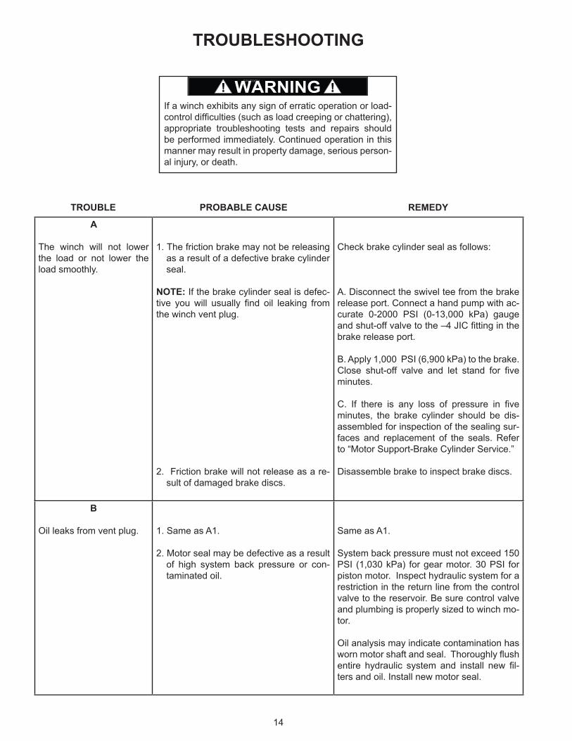
TROUBLESHOOTING
A
The winch will not lower the load or not lower the load smoothly.
1. The friction brake may not be releasing as a result of a defective brake cylinder seal.
NOTE: If the brake cylinder seal is defec-tive you will usually find oil leaking from the winch vent plug.
2. Friction brake will not release as a re-sult of damaged brake discs.
Check brake cylinder seal as follows:
A. Disconnect the swivel tee from the brake release port. Connect a hand pump with ac-curate 0-2000 PSI (0-13,000 kPa) gauge and shut-off valve to the –4 JIC fitting in the brake release port.
B. Apply 1,000 PSI (6,900 kPa) to the brake. Close shut-off valve and let stand for five minutes.
C. If there is any loss of pressure in five minutes, the brake cylinder should be dis-assembled for inspection of the sealing sur-faces and replacement of the seals. Refer to “Motor Support-Brake Cylinder Service.”
Disassemble brake to inspect brake discs.
B
Oil leaks from vent plug. 1. Same as A1.
2. Motor seal may be defective as a result of high system back pressure or con-taminated oil.
Same as A1.
System back pressure must not exceed 150 PSI (1,030 kPa) for gear motor. 30 PSI for piston motor. Inspect hydraulic system for a restriction in the return line from the control valve to the reservoir. Be sure control valve and plumbing is properly sized to winch mo-tor.
Oil analysis may indicate contamination has worn motor shaft and seal. Thoroughly flush entire hydraulic system and install new fil-ters and oil. Install new motor seal.
TROUBLE PROBABLE CAUSE REMEDY
If a winch exhibits any sign of erratic operation or load- control difficulties (such as load creeping or chattering), appropriate troubleshooting tests and repairs should be performed immediately. Continued operation in this manner may result in property damage, serious person-al injury, or death.

15
CThe brake will not hold a load with the control lever in neutral.
1. Excessive system back pressure acting on the brake release port.
2. Friction brake will not hold due to worn or damaged brake discs.
3. Brake clutch is slipping.
Same as remedy for Trouble B2.
Same as remedy for Trouble A2.
Improper planetary gear oil may cause the brake clutch to slip. Drain old gear oil and flush winch with solvent. Thoroughly drain solvent and refill winch with recommended planetary gear oil listed in “Preventive Main-tenance.”
Brake clutch may be damaged or worn. Dis-assemble and inspect brake clutch as de-scribed in “Brake Clutch Service.”
DThe winch will not hoist the rated load.
1. The winch may be mounted on an un-even or flexible surface which causes distortion of the winch base and bind-ing of the gear train. Binding in the gear train will absorb horsepower needed to hoist the rated load and cause heat.
2. System relief valve may be set too low. Relief valve needs adjustment or re-pair.
3. Be certain hydraulic system tempera-ture is not more than 180°F (82°C). Excessive hydraulic oil temperatures increase motor internal leakage and re-duce motor performance.
4. Winch line pull rating is based on 1st layer of wire rope.
5. Rigging and sheaves not operating ef-ficiently.
Reinforce mounting surface.
If necessary, use shim stock to level winch. Refer to “Winch Installation.”
First loosen, then evenly retighten all winch mounting bolts to recommended torque.
Check relief pressure as follows:
A. Install an accurate 0-4000 PSI (28,000 kPa) gauge into the inlet port of the brake valve.
B. Apply a stall pull load on the winch while monitoring pressure.
C. Compare gauge reading to winch specifi-cations. Adjust relief valve as required.
NOTE: If pressure does not increase in pro-portion to adjustment, relief valve may be contaminated or worn out. In either case, the relief valve may require disassembly or replacement.
Same as remedies for Trouble D1 and D2.
Same as remedies for Trouble E2.
Refer to winch performance charts for ad-ditional information.
Perform rigging service as recommended by crane manufacturer.
TROUBLE PROBABLE CAUSE REMEDY

16
EThe winch runs hot. 1. Same as D1.
2. Be certain that the hydraulic system temperature is not more than 180°F (82°C). Excessive hydraulic oil tem-peratures may be caused by:
A. Plugged heat exchanger.
B. Too low or too high oil level in hydraulic reservoir.
C. Same as D2.
D. Hydraulic pump not operating efficient-ly.
3. Excessively worn or damaged internal winch parts.
Same as remedies for Trouble D1.
Thoroughly clean exterior and flush interior.
Fill/drain to proper level.
Same as remedies for Trouble D2.
Prime mover low on horsepower or RPM Tune/adjust prime mover.
Check suction line for damage.
If pump is belt driven, belts are slipping. Re-place/tighten belts.
Pump worn. Replace pump.
Disassemble winch to inspect/replace worn parts.
FWinch chatters while rais-ing rated load.
1. Same as D2.
2. Hydraulic oil flow to motor may be too low.
3. Controls being operated too quickly.
Same as remedies for Trouble D2.
Same as remedies for Trouble E2.
Conduct operator training as required.
GThe wire rope does not spool smoothly on the drum.
1. The winch may be mounted too close to the main sheave, causing the fleet angle to be more than 1-1/2 degrees.
2. The winch may not be mounted perpen-dicular to an imaginary line between the center of the cable drum and the first sheave.
3. Could possibly be using the wrong lay rope. There is a distinct advantage in applying rope of the proper direction of lay. When the load is slacked off, the several coils on the drum will stay closer together and maintain an even layer. If rope of improper lay is used, the coils will spread apart each time the load is removed. Then, when winding is resumed, the rope has a tendency to criss-cross and overlap on the drum. The result is apt to be a flattened and crushed rope.
4. The winch may have been overload-ed, causing permanent set in the wire rope.
Check mounting distance and fleet angle. Reposition winch as required.
Refer to “Winch Installation.”
Consult wire rope manufacturer for recom-mendation of wire rope that best suits your application.
Replace wire rope and conduct operator/ rigger training as required.
TROUBLE PROBABLE CAUSE REMEDY

17
Before any part is removed from the winch or drive gear-box, all service instructions should be read and under-stood.
Work in a clean, dust free area as cleanliness is of utmost importance when servicing hydraulic equipment.
Inspect all replacements parts, prior to installation, to de-tect any damage which might have occurred in shipment.
Use only genuine BRADEN replacement parts for opti-mum results. Never reuse expendable parts such as O-rings and oil seals.
Inspect all machined surfaces for excessive wear or dam-age before reassembly operations are begun.
Lubricate all O-rings and oil seals with gear oil prior to installation.Lubricate all bearings with an oil soluble grease prior to assembly.
Use a sealing compound on the outside surface of oil seals and a light coat of thread sealing compound on pipe threads. Avoid getting sealing compound inside parts or passages which conduct oil.
Before beginning to disassemble the winch or drive gear-box, remove the wire rope, drain the oil and clean the out-side surfaces to avoid contaminating gears and bearings.
Item numbers shown in service procedures are referenced to the exploded-view drawing in this manual.
WINCH DISASSEMBLY1. Stand the winch of the end opposite the motor. Re-
move the hydraulic hose that connects the brake valve and motor to the brake release port. Remove the four capscrews securing the motor to the winch and lift off the motor/brake valve assembly. Remove and discard the O-ring installed on the outside of the motor pilot.
2. Remove the four capscrews from the motor adapter
and remove the motor adapter (Item 27) from the drive gearbox. Remove and discard the O-ring (Item 26) from the motor adapter.
3. Remove the 10 capscrews and lockwashers securing the end bracket (Item 25) to the gearbox.
4. Remove the 24 capscrews and lockwashers securing the tie plates (Item 1) to both end brackets and remove the tie plates. The tie plates have two dowel pins in each end and may have to be lightly tapped or pried from the end brackets. Install four large C-clamps around the drum support end bracket (Item 2) and the drum flange. This will prevent the end bracket and drum from sepa-rating when the motor end bracket and winch drive are removed.
5. Lift the motor end bracket (Item 25) from the drum/drive assembly.
SERVICE PRECAUTIONS

18
6. There are two large notches in the end of the drive gearbox. These must be rotated to gain access to the capscrews and lockwashers (Items 4 and 5) that secure the gearbox to the winch drum. This is done by rotating the motor coupling while keeping the drum from turning. Continue this procedure and remove all capscrews and lockwashers (Items 4 and 5).
NOTE: To obtain relative movement between the two sections of the gearbox, the input shaft must be rotated in the same direction as the motor turns to haul-in ca-ble. Rotating the shaft in the opposite direction results in the entire gearbox and drum turning as a single unit.
7. The brake clutch assembly and motor coupling should now be removed from the gearbox.
NOTE: The sun gear will remain in the gearbox and cannot be removed from this end.
8. Lift the winch drive gearbox out of the drum using two 7/8 NC eyebolts spaced 180 degrees apart as lifting lugs. Refer to Winch Drive/Gearbox Service section for further disassembly of winch drive.
DRUM SUPPORT END BRACKET SERVICEIf the winch disassembly procedure has been followed to this point, remove the C-clamps installed in step 4. If only this end of the winch is being serviced, support the winch on the motor end bracket and remove the 12 capscrews and lockwashers securing the end of both tie plates (Item 1), to the drum support end bracket (Item 2). Loosen the 12 capscrews on the other end of both tie plates just enough to allow the tie plates to be pried free of the dowel pins in the drum support end bracket.
1. Lift the support end bracket from the drum. NOTE: If the winch disassembly procedure was fol-
lowed and the drum is on top of the end bracket, lift the drum from the support end bracket.
DO NOT attempt to remove the large retaining ring at this time. It is holding the static brake spring in com-pression. Removing this retaining ring at this time could result in property damage, personal injury, or death.

19
105
106
15
20
21
19
45
11
10
322
3
23
2
7
13
12
14
8
9
6
18
17
15
16
31
1
24
68
69
70
71
69
64
73
74
75
76
79
77
61
63
62
61
56
67
65
66
72
58
57
64
60
59
56
55
40
41
42
44
43
81
82
4
5
45
80
51
52
53
47
46
50
49
48
78
75
74
83
84
85
32
54
95
86
87
88
89
90
95
96
97
98
99
100
101
28
91
92
93
94102
103
104 26
27
433
30
29
25

20
Two-
spee
dM
otor
Sing
le-s
peed
Mot
or
ITEM
ITEM
ITEM
ITEM
NU
MB
ER D
ESC
RIP
TIO
NN
UM
BER
DES
CR
IPTI
ON
NU
MB
ER D
ESC
RIP
TIO
NN
UM
BER
DES
CR
IPTI
ON
1Ti
e P
late
31D
owel
Pin
67S
econ
d S
tage
Pla
net C
arrie
r97
Rol
ler B
earin
g2
Sup
port
End
Pla
te32
Pip
e P
lug
68P
lane
t Pin
98S
pace
r3
O-R
ing
Flus
h P
lug
33C
apsc
rew
69Th
rust
Was
her
99S
prag
Clu
tch
Ass
embl
y4
Lock
was
her
40Th
rust
Was
her
70S
econ
d S
tage
Pla
net G
ear
100
Spa
cer
5C
apsc
rew
41Th
rust
Was
her
71Lo
ose
Rol
lers
101
Inte
rnal
Ret
aini
ng R
ing
6O
uter
Bea
ring
Hub
42P
rimar
y R
ing
Gea
r/End
Cov
er72
Out
put P
lane
t Car
rier
102
Spr
ag C
lutc
h In
ner R
ace
7In
tern
al R
etai
ning
Rin
g43
Cap
scre
w73
Pla
net P
in10
3S
pace
r8
Rol
ler B
earin
g44
Lock
was
her
74B
earin
g C
one
104
Inte
rnal
Ret
aini
ng R
ing
9G
reas
e Fi
tting
45R
ing
Gea
r75
Bea
ring
Cup
105
Cab
le W
edge
(01
& 0
2 D
rum
)10
Inne
r Bea
ring
Hub
46D
rain
Tub
e76
Out
put P
lane
t Gea
r10
6C
able
Wed
ge (0
3 &
04
Dru
m)
11E
xter
nal R
etai
ning
Rin
g47
Plu
g77
Bea
ring
Spa
cer
120
Hyd
raul
ic M
otor
12S
eal
48S
plit
Rin
g78
Inte
rnal
Ret
aini
ng R
ing
121
O-R
ing
13S
eal C
arrie
r49
Bea
ring
Con
e79
Rol
lpin
122
Lock
was
her
14O
-Rin
g50
Bea
ring
Cup
80P
lug
123
Cap
scre
w15
Lock
was
her
51B
earin
g C
up81
Inte
rnal
Ret
aini
ng R
ing
124
Bra
ke V
alve
16C
apsc
rew
52B
earin
g C
one
82B
rake
Spa
cer/S
uppo
rt P
late
125
O-R
ing
17C
apsc
rew
53M
etal
Fac
e S
eal
83S
teel
Bra
ke D
isk
126
Cap
scre
w18
Lock
was
her
54V
ent P
lug
84Fr
ictio
n B
rake
Dis
k12
7R
educ
er E
lbow
19S
ight
Gau
ge55
Prim
ary
Sun
Gea
r85
Mot
or S
uppo
rt/B
rake
Cyl
inde
r12
8H
ydra
ulic
Hos
e20
Cap
scre
w56
Ext
erna
l Ret
aini
ng R
ing
86B
ack-
Up
Rin
g12
9E
lbow
Fitt
ing
21C
over
Pla
te57
Thru
st W
ashe
r87
O-R
ing
130
Elb
ow F
ittin
g22
O-R
ing
58S
econ
d S
tage
Sun
Gea
r88
O-R
ing
131
Hyd
raul
ic H
ose
23C
able
Dru
m59
Prim
ary
Pla
net C
arrie
r89
Bac
k-U
p R
ing
132
Tee
Fitti
ng24
O-R
ing
60P
lane
t Pin
90B
rake
Pis
ton
133
Nee
dle
Val
ve25
Mot
or E
nd P
late
61Th
rust
Was
her
91B
rake
Spr
ing
134
Elb
ow F
ittin
g26
O-R
ing
62P
rimar
y P
lane
t Gea
r92
Bra
ke P
isto
n S
top
135
Hyd
raul
ic H
ose
27M
otor
Ada
pter
63Lo
ose
Rol
lers
93S
prin
g S
top
136
Mal
e B
ranc
h Te
e Fi
tting
28M
otor
Cou
plin
g64
Rol
lpin
94In
tern
al R
etai
ning
Rin
g13
7C
ap N
ut29
Cap
scre
w65
Thru
st W
ashe
r95
Bus
hing
138
Nip
ple
30Lo
ckw
ashe
r66
Out
put S
un G
ear
96S
prag
Clu
tch
Out
er R
ace
139
Elb
ow F
ittin
g14
0W
arni
ng T
ag

21
2. The bearing carrier/end cap (Item 6) is in the end brack-et, and the bearing support (Item 10) is in the drum. Remove the retaining ring (Item 7) and the seal carrier and seal (Items 13 and 12). Remove and discard O-ring (Item 14). Remove the seal from the seal carrier and discard.
Thoroughly clean all parts and inspect for damage and wear. The bearing rollers should not exhibit any irregulari-ties. If the rollers show any sign of spalling, corrosion, dis-coloration, material displacement or abnormal wear, the bearing should be replaced.
Apply a nonhardening sealant to the outside diameter of a new seal. Install the seal into the seal carrier as shown above. Install a new O-ring against the outer race of the bearing and install the seal carrier into the bearing carrier/end cap. Install a new retaining ring into the groove in the end cap. Liberally pack the bearing and end cap with grease. The end bracket can now be placed on the drum, or the drum placed on the end bracket, depending on your method of assembly.
WINCH DRIVE/GEARBOX SERVICEDISASSEMBLY
1. Stand the drive on the input end and remove the 12 capscrews and lockwashers (Items 43 and 44) securing
the end cover/primary ring gear to the drive assembly and remove the cover from the drive.
2. Remove the primary sun gear (Item 55).
3. Remove the primary planet assembly. The second stage sun gear (Item 58) will come out with the planet assembly. If the thrust washer (Item 57) between the primary and second stage planet assemblies stayed in the gearbox, remove it and set it aside with the primary planet assembly.
4. Remove the second stage planet assembly. The out-put sun gear (Item 66) will come out with the planet assembly. If the thrust washer (Item 65) between the

22
second stage and output planet assemblies stayed in the gearbox, remove it and set it aside with the second stage planet assembly.
5. The output planet carrier has two tapped holes (1/2 – 13) which can be used to lift the assembly out of the ring gear. Install 2 eyebolts into these holes and use them to lift the output planet assembly out of the ring gear. Because of the weight of the assembly, it may be advisable to use a small hoist for this operation.
6. Using a long bar or blunt chisel, separate the ends of the split ring (Item 48) and remove both halves of the split ring from the motor support. Turn the assembly over so the motor support is facing up. Because the bearing cone (Item 49) will fall the length of the ring gear in the next step, the assembly should be setting on a wooden board or put several rags in the bottom of the ring gear to prevent damage to the bearing.
7. Install three 7/8 – 9x6-inch long capscrews equally spaced around the motor support (Item 85) until they contact the ring gear (Item 45). Alternately tighten each capscrew 1/2 to 1 turn at a time to lift the motor sup-port out of the ring gear. When the two pieces have been separated, you will hear the bearing cone (Item 49) drop to the bottom of the ring gear.
8. Install two 3/4–10 eyebolts in 2 of the motor mounting holes and use them to lift the motor support/brake as-sembly out of the ring gear.
SUBASSEMBLY SERVICEPRIMARY RING GEAR/END COVER
1. Thoroughly clean and inspect the cover/ring gear. Check the ring gear teeth for nicks, spalling or exces-sive wear. Replace if wear is greater than 0.015 inch (0.4 mm) when compared to unworn area of teeth. The only serviceable parts in the ring gear/cover are the two thrust washers (Items 40 and 41). Inspect them for signs of abnormal wear or damage and replace as required. Inspect the inside of the cover for signs of contact with the primary sun gear and/or primary planet carrier. If signs of contact are seen, replace both thrust washers.

23
BRAKE ASSEMBLYDISASSEMBLY
1. Install the spring compressor tool as show. If a hydrau-lic press is available, only part A of the tool is required. Tighten the nut above part A or apply hydraulic pressure to slightly compress the spring and relieve load on the retaining ring (Item 94). Carefully remove the retaining ring.
2. Slowly and carefully unscrew the nut above part A until spring pressure is completely released (spring travel is approximately 4 inches [10 cm]). Remove the compres-sor tool.
3. Remove the spring stop (Item 93), spring (Item 91) and piston stop (Item 92) from the brake cylinder.
4. Remove the brake piston (Item 90). Remove and dis-card both sets of piston O-rings and backup rings (Items 86, 87, 88, 89).
5. Turn the assembly over to access the brake plates. Re-move the retaining ring (Item 81). Remove the spacer plate (Item 82), steel separator discs (Item 83) and fric-tion discs (Item 84).
Thoroughly clean and inspect all parts, paying close at-tention to the sealing surfaces of the brake piston. Place each friction disc on a flat surface and check for distortion with a straight edge. Friction material should appear even across the entire surface and the groove pattern should be visible. Replace friction discs if splines are worn to a point, disc is distorted, friction material is worn unevenly or groove pattern is no longer visible. Place each steel brake plate on a flat surface and check for distortion with a straight edge. Check surface for signs of material transfer or heat. Replace steel discs if splines are worn to a point, disc is distorted or heat discolored.
Check the brake release passage to be sure it is clean and completely open.
Inspect both sets of large tapered roller bearings (Items 49, 50, 51, 52) for signs of damage or excessive wear. The bearing rollers should not exhibit any irregularities. If the rollers show any sign of spalling, corrosion, discolor-ation, material displacement or abnormal wear, the bear-ing should be replaced. Likewise, the cage should be in-spected for wear or deformation. If there is any damage that would impair the cage’s ability to separate, retain and guide the rollers properly, the bearing should be replaced.

24
Carefully inspect both halves of the metal face seal be-tween the motor support/brake cylinder and the ring gear. If the metal contact faces show signs of excessive wear or mechanical damage, or the rubber rings are brittle or damaged, the seal should be replaced.
ASSEMBLY
1. Set the motor support/brake cylinder on a bench with the motor end down.
2. Starting with a steel disc, alternately install a steel then a friction disc until nine of each type disc have been installed (ending with a friction disc). It is advisable to lightly lubricate the brake discs with oil that will be used in the winch prior to assembly.
3. Install the spacer plate (Item 82) on top of the last fric-tion disc.
4. Install the retaining ring (Item 81). Turn the assembly over with the motor end up and be sure all brake plates are stacked squarely against the spacer plate.
5. Install new O-rings and backup rings (Items 86 and 87, 88 and 89) into the brake cylinder as shown. It is VERY important to position the O-rings and backup rings as shown above to prevent brake cylinder leakage.
6. Lightly lubricate the sealing surfaces of the brake pis-ton (Item 90) and install it into the brake cylinder until it touches the brake discs.

25
7. Install the piston stop (Item 92) and the brake spring (Item 91).
8. Set the spring stop (Item 93) on the spring and install the spring compressor tool, or move the assembly to a press. Be sure the step on the compressor tool is squarely seated on the spring stop.
9. Slowly compress the spring until the spring stop is slightly below the retaining ring groove in the motor sup-port. Install the retaining ring (Item 94).
NOTE: The holes in the ends of the retaining ring are slightly tapered. The smaller end of the hole MUST be installed away from the spring stop, or toward the motor, to prevent the ring from slipping off the pliers when installed or removed. Be sure the retaining ring is completely seated in its groove, and slowly release the spring compressor until the force of the spring is held by the retaining ring. Remove the spring compressor tool.
Brake Cylinder Pressure Test1. Connect a hydraulic hand pump with an accurate gauge
and shut-off valve to the brake release port of the motor support. Apply 500 PSI (3,450 kPa) to the brake. Close the shut-off valve and let stand for five minutes. If there is any loss of pressure, the brake cylinder should be disassembled for inspection of the sealing surfaces and O-rings.
WHILE PRESSURE IS APPLIED AND THE BRAKE IS RELEASED, install the sprag clutch assembly. Rotate the clutch back and forth to align the splines in all brake discs. When the sprag clutch has engaged all the discs, release the pressure on the brake cylinder and remove the sprag clutch.
Sprag Clutch AssemblyBefore disassembling the sprag clutch, make note of the freewheeling direction of the inner brake race (Item 102). Hold the outer race (Item 96) and try to turn the inner race in both directions. It should turn free of the outer race in one direction only. If the inner race will not turn freely in either direction, or turns freely in both directions, the sprag clutch assembly has been damaged and must be replaced.
1. Remove the retaining ring (Item 104). All other internal parts can now be removed, including the sprag assem-bly (Item 99) and the roller bearing (Item 97).
2. Thoroughly clean all parts in solvent and inspect for signs of wear and/or damage. Inspect the sprag clutch and roller bearing closely for abnormal wear, cracks, pitting or corrosion. Check small clips for breakage or bright spots; the signs of excessive wear.
3. Apply a light coat of gear box lubricant to all components as they are assembled. Install the roller bearing (Item 97) into the outer race (Item 96). Install spacer (Item 98) on top of roller bearing. Install the sprag clutch as-sembly (Item 99). NOTE: The sprag assembly con-sists of three parts; two U-shaped bronze spacers and a cam assembly. The bronze spacers are installed with their open end toward the cam assembly, one spacer on each side. Rotate the cam assembly while gently pressing it into the outer race.
Before installing the inner race (Item 102), be sure the internal retaining ring (Item 101) is installed and fully seat-ed. Slide the inner race through the sprag clutch (the race will have to be rotated in the freewheeling direction to start it into the clutch). Be sure the inner race turns freely in the same direction determined before the unit was disas-sembled. If it turns freely in the opposite direction, the sprag clutch has been installed backwards and must be reversed. Install spacers (Items 100 and 103), and retain-ing ring (Item 104).
The brake spring must be compressed approximately 4 inches (10 cm) and has a compressed force of ap-proximately 1,500 lb (680 kg). Extreme care should be observed while completing this step to avoid sudden release of the spring. DO NOT stand directly in front of the spring while it is being compressed.
CAUTIONThe polished surfaces of the inner and outer races must be perfectly smooth to ensure positive engagement of the clutch. The slightest defect may reduce sprag clutch effectiveness, which could result in property damage, personal injury, or death. The entire sprag clutch as-sembly must be replaced if any component is defective.

26
PLANET CARRIER SERVICE
OUTPUT PLANET CARRIER
1. The preferred method of removing the planet pin (Item 73), is to first remove the roll pin (Item 79). This can usually be done by using a punch or small pry bar to drive or push the roll pin out of the planet carrier (Item 72). Access to the roll pin is gained through a drilled hole in the end of the planet pin. If this method is not successful, the roll pin must be sheared by driving or pressing the planet pin out of the carrier. A piece of pipe or tubing long enough to hold the planet pin may be used to support the carrier while each pin is re-moved. Adequately support the assembly and drive or press out one planet pin, shearing the roll pin.
2. Slide the planet gear out of the carrier and remove the bearing cones. Clean and inspect the bearing cups in each end of the gear. If they are determined to be in serviceable condition, no further disassembly is re-quired.
3. If the bearings need to be replaced, remove the bear-ing cups, spacer and internal retaining ring from the bore of the planet gear.
4. Repeat steps 1, 2 and 3 for each planet gear.
Thoroughly clean all parts and inspect for damage and wear. The bearings should be examined for any signs of spalling, corrosion, discoloration, material displacement or abnormal wear. The bearing cages should be inspected for wear or deformation. If any of these conditions are found, the bearing should be replaced. Gears should be inspected for abnormal wear or pitting and replaced as necessary. Inspect all machined surfaces and bearing bores for signs of damage or excessive wear.
NOTE: Steps 5 through 8 are necessary only if the planet gear bearings are being replaced.
5. Install a retaining ring (Item 78) in the bore of a planet gear. Be sure it is completely seated in the groove.
6. Install a bearing spacer (Item 77) into the bore of the planet gear. Be sure the step on the spacer is toward the retaining ring.
7. Install a bearing cup (Item 75) into each end of the gear. The cups should firmly contact the spacer.
8. Repeat steps 5, 6 and 7 for each planet gear.
9. Install a bearing cone (Item 74) into each end of a planet gear and slide the gear and bearings into the planet carrier, aligning the bearing bores with the plan-et pin bore.
10. Install a planet pin through the planet carrier and bear-ings, aligning the hole in the pin with the roll pin hole in the carrier. Drive a new roll pin (Item 79) into place in the carrier.
NOTE: Always use NEW roll pins.

27
11. The roll pin should be slightly recessed in the carrier when properly installed. Use a punch to stake the car-rier next to the pin hole so the pin will not back out when the unit is in operation.
12. Repeat steps 9, 10 and 11 for each planet gear.
PRIMARY AND SECONDARYPLANET CARRIERS
1. The preferred method of removing the planet pin, is to first remove the roll pin. This can usually be done by using a punch or small pry bar to drive or push the roll pin out of the planet carrier. Access to the roll pin is gained through a drilled hole in the end of the planet pin. If this method is not successful, the roll pin must be sheared by driving or pressing the planet pin out of the carrier. A piece of pipe or tubing long enough to hold the planet pin may be used to support the carrier while each pin is removed. Adequately support the as-sembly and drive or press out one planet pin, shearing the roll pin.
2. Slide the planet gear out of the carrier and remove the thrust washers and loose roller bearings.
3. Repeat steps 1 and 2 for each planet gear.
4. Remove the retaining ring holding the sun gear in the planet carrier and remove the sun gear.
Thoroughly clean all parts and inspect for damage and wear. The bearing rollers should be examined for any signs of spalling, corrosion, discoloration, material dis-placement or abnormal wear. If any of these conditions are found, the rollers should be replaced. Gears should be inspected for abnormal wear or pitting and replaced as necessary. Inspect all machined surfaces and bearing bores for signs of damage or excessive wear.
5. Engage the sun gear with the splines on the planet carrier and install the retaining onto the sun gear.
6. Liberally coat the bore of a planet gear with a good grade of oil soluble grease.
7. Set a thrust washer on a clean flat work surface. Set the planet gear on the thrust washer with the bore in the gear centered over the washer. Install a row of loose rollers around the bore of the gear, using addi-tional grease as required to hold them in place.
8. Set another thrust washer on top of the rollers and slide the gear and bearing assembly into place in the planet carrier. Align the gear with one of the planet pin bores in the carrier and install a planet pin. Align the hole in the pin with the hole in the carrier and install a new roll pin.
NOTE: Always use NEW pins.
9. The roll pin should be slightly recessed in the carrier when properly installed. Use a punch to stake the car-rier next to the pin hole so the pin will not back out when the unit is in operation.
10. Repeat steps 5 through 9 for the remaining planet gears.

28
The following procedure should be used to assemble a complete winch and drive gearbox. It assumes all sub-assemblies have been properly serviced as described in previous sections of this manual.
1. If the metal seal (Item 53) is being replaced, install one half of the seal in the motor support and the other half in the ring gear. The old seal is simply pried out of its seat. Clean the seal seat area in both the motor sup-port and ring gear.
NOTE: Handle the new seals with care. The metal contact areas must remain perfectly flat and free of nicks or dents for the seal to operate leak free.
Apply a liberal coat of oil soluble grease to the new seal O-rings and install one O-ring on each seal half. Each seal half can then be gently worked into its seat in the motor support and ring gear.
2. If the tapered roller bearings (Items 49, 50, 51, 52) are being replaced, install bearing cone (Item 52) onto the motor support. Install both bearing cups (Items 50 and 51) into the ring gear. Set the motor support on your workbench with the motor end down. Apply a light coat of oil to the mating surfaces of the metal seal, and set the ring gear down onto the motor support. Mat-ing surfaces of the seal should be in contact with each other and the ring gear should rotate smoothly.
WINCH ASSEMBLY
3. Install the bearing cone (Item 49) onto the motor sup-port. Use a bar or flat ended punch to fully seat the bearing. Again check that the ring gear rotates freely.
4. Install two large C-clamps between the flanges of the motor support and ring gear. Tighten the C-clamps firmly and again fully seat the bearing installed in step 3. Install both halves of the split ring (Item 48) into the groove on the motor support. A 1-inch diameter bar and various sizes of steel blocks or key stock can be used, if necessary, to force the split ring halves into the groove. Be careful to avoid damaging the ring gear teeth while installing the split ring. Remove the two C-clamps.
5. Install 2 each 1/2–13 eyebolts into the output planet carrier and use them to set the planet assembly into the ring gear. Rotate the planet carrier to engage the splines on the motor support. In addition to engaging the splines, the planet carrier must drop down over the split ring halves, holding them in position.

29
6. Install thrust washer (Item 65), onto the second stage planet assembly (with output sun gear). A light coat of oil soluble grease should be used to hold it in place during assembly. Slide the planet assembly into the ring gear and engage the output sun gear with the output planet gears. The second stage planet gears should now be at least 1/8 inch (3 mm) below the top of the teeth cut into the ring gear. If they are above the ring gear teeth, the unit is not properly assembled to this point. Either the thrust washer (Item 65) is improp-erly positioned, or the output planet carrier is not fully engaged onto the motor support (possibly caused by the split ring not being fully seated). Remove the sec-ond stage planet assembly and/or the output planet assembly to determine and correct the cause of the problem before proceeding.
7. Install thrust washer (Item 57) onto the primary planet assembly (with second stage sun gear). A light coat of oil soluble grease should be used to hold it in place during assembly. Install the primary planet assembly onto the second stage planet assembly, engaging the second stage sun gear with the second stage planet gears. Visually check to be sure the thrust washer is properly positioned.
8. Install the primary sun gear (Item 55) through the cen-ter of the primary planet assembly.
9. Carefully set the cover (Item 42) onto the main ring gear, engaging the primary planet gears with the gear teeth machined into the cover. Turn the cover to align the bolt holes with those in the main ring gear and in-stall all 12 capscrews and lockwashers (Items 43 and 44).
In the following step, the primary ring/cover may sud-denly drop on the main ring gear when all primary sun gear teeth are aligned with those in the cover. DO NOT work with your fingers between the cover and the main ring gear.
CAUTION

30
10. Turn the unit over and visually check to see if all inter-nal teeth on the brake discs are aligned. If they are not aligned, connect a hand operated hydraulic pump to the brake release port and apply 500 PSI (3,450 kPa). This will allow the brake plates to be rotated and aligned as the sprag clutch assembly is installed. Install the sprag clutch assembly. The top of the sprag assembly should be just below the spring stop (Item 93) when installed completely. If a hand pump was used, release the pressure and remove the pump.
11. Carefully set the cable drum onto the support end bracket (Item 2). Pay careful attention that the bearing is not damaged and engages properly.
12. Install 2 eyebolts into the winch drive assembly and use them to lift the drive. While the drive is suspended, install a new O-ring (Item 24) under the lower flange of the drive. Carefully set the drive into the winch drum, aligning the holes in the drum with those in the bottom flange of the drive.
13. There are two large notches in the end of the drive gearbox. These must be rotated to install the cap-screws and lockwashers (Items 4 and 5) that secure the gearbox to the winch drum. This is done by rotat-ing the motor coupling while keeping the drum from turning. Continue this procedure and install all cap-screws and lockwashers (Items 4 and 5). NOTE: To obtain relative movement between the two sections of the gearbox, the input shaft must be rotated in the same direction as the motor turns to haul-in cable. Ro-tating the shaft in the opposite direction results in the entire gearbox and drum turning as a single unit.
14. Install the motor end bracket (Item 25) onto the winch drive. Be sure to orient the end bracket so the vent plug will be as close as possible to the 12:00 o’clock position when the winch is installed.
15. Install the 10 capscrews and lockwashers (Items 29 and 30) securing the end bracket to the winch drive. If necessary, rotate the motor end bracket until it is aligned with the support end bracket.

31
16. Install the two tie plates between the two end brackets, using the dowels in the end brackets to align and posi-tion them. Install all 24 capscrews and lockwashers (Items 15 and 16) securing the tie plates to the end brackets.
17. Install a new O-ring (Item 26) onto the motor adapter. Install the motor adapter into the winch drive using four capscrews and lockwashers (Items 33 and 4).
18. Install the motor coupling into the inner race of the sprag clutch.
19. Install a new O-ring (Item 121) onto the pilot of the hy-draulic motor. Install the hydraulic motor into the mo-tor adapter, engaging the motor splines with the motor coupling. Install the four capscrews and lockwashers (Items 122 and 123), securing the motor to the motor adapter. Connect the brake release hose to the brake release port on the winch drive.
32
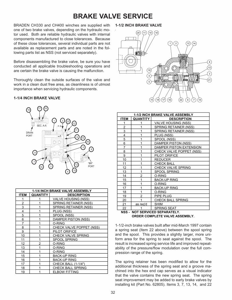
BRADEN CH330 and CH400 winches are supplied with one of two brake valves, depending on the hydraulic mo-tor used. Both are reliable hydraulic valves with internal components manufactured to close tolerances. Because of these close tolerances, several individual parts are not available as replacement parts and are noted in the fol-lowing parts list as NSS (not serviced separately).
Before disassembling the brake valve, be sure you have conducted all applicable troubleshooting operations and are certain the brake valve is causing the malfunction.
Thoroughly clean the outside surfaces of the valve and work in a clean dust free area, as cleanliness is of utmost importance when servicing hydraulic components.
1-1/4 INCH BRAKE VALVE
1-1/2 INCH BRAKE VALVE
1-1/2-inch brake valves built after mid-March 1997 contain a spring seat (Item 22 above) between the spool spring and the spool. This provides a slightly larger, more uni-form area for the spring to seat against the spool. The result is increased spring service life and improved repeat-ability of the pressure/flow modulation over the full com-pression range of the spring.
The spring retainer has been modified to allow for the additional thickness of the spring seat and a groove ma-chined into the hex end cap serves as a visual indicator that the valve contains the new spring seat. The spring seat improvement may be added to early brake valves by installing kit (Part No. 62805). Items 3, 7, 13, 14, and 22
BRAKE VALVE SERVICE
1221 14
19
4
5
15 18 17 16
21
3
13
146 7
8
22
20 11 1910
A
A
SEC. A-A
DRAINPORT
31
2
4
5
6 1416
11
12
10
7
89
13
15
181719
“BR”PORT
22
ITEM QUANTITY DESCRIPTION1 1 VALVE HOUSING (NSS)2 1 SPRING RETAINER (NSS)3 1 SPRING RETAINER (NSS)4 1 PLUG (NSS)5 1 SPOOL (NSS)6 1 DAMPER PISTON (NSS)7 1 O-RING8 1 CHECK VALVE POPPET (NSS)9 1 PILOT ORIFICE10 1 CHECK VALVE SPRING11 1 SPOOL SPRING12 2 O-RING13 1 O-RING14 1 O-RING15 1 BACK-UP RING16 1 BACK-UP RING17 1 CHECK BALL (1-1/4")18 1 CHECK BALL SPRING19 1 ELBOW FITTING
1-1/4 INCH BRAKE VALVE ASSEMBLY
ITEM QUANTITY DESCRIPTION1 1 VALVE HOUSING (NSS)2 1 SPRING RETAINER (NSS)3 1 SPRING RETAINER (NSS)4 1 PLUG (NSS)5 1 SPOOL (NSS)6 1 DAMPER PISTON (NSS)7 1 DAMPER PISTON EXTENSION8 1 CHECK VALVE POPPET (NSS)9 1 PILOT ORIFICE
10 1 REDUCER11 1 CHECK BALL12 1 CHECK VALVE SPRING13 1 SPOOL SPRING14 2 O-RING15 1 BACK-UP RING16 1 O-RING17 1 BACK-UP RING18 1 O-RING19 2 PIPE PLUG20 1 CHECK BALL SPRING21 as req'd SHIM22 1 SPRING SEAT
NSS -
1-1/2 INCH BRAKE VALVE ASSEMBLY
NOT SERVICED SEPARATELY.ORDER COMPLETE VALVE ASSEMBLY.

33
shown above are included in the kit. We recommend that this kit be installed whenever the brake valve is removed for inspection or service.
It is always a good practice to check the initial opening or cracking pressure of the brake valve whenever the hoist is serviced or inspected. Refer to BRADEN Service Bulletin number 527 for complete brake valve test and adjustment procedures.
DISASSEMBLY
1. On the 1-1/4-inch valve only, remove the pilot orifice from the brake release port using a 5/32-inch Allen wrench.
1-1/4-inch Valve
1-1/2-inch Valve
2. Remove the fitting, motor drain check ball and spring.
1-1/4-inch Valve
1-1/2-inch Valve
3. Remove the spool spring retainer and spool spring. Remove the spool plug and carefully remove the spool assembly. Remove the damper piston from the spool. The piston will come out of the spool slowly, because of a partial vacuum formed between the two. Use extreme care to avoid damaging the polished surfaces of either piece.
1-1/4-inch Valve
1-1/2-inch Valve
4. Remove the check valve spring retainer, spring and check valve poppet.
CLEAN AND INSPECT
1. Discard all O-rings and backup rings. Clean all parts in solvent and blow dry. Inspect polished surfaces of spool and damper piston for damage that may cause

34
binding or leakage. Inspect spool bore in valve hous-ing for damage or scoring. Inspect check valve seat in valve housing and check valve poppet. If the spools, bores or valves are damaged, the entire valve must be replaced as these parts are not serviced separately. Check the free length of the main piston spring. For the 1-1/4-inch valve, replace if less than 1-15/16 inches (49.2 mm) long. For the 1-1/2-inch valve, replace if less than 3-7/16 inches (87.3 mm) long. Check the free length of the check valve spring. Replace if less than 1-1/2 inches (38.1 mm) long.
1-1/4-inch Valve
1-1/2-inch Valve
2. Inspect the 0.020-inch (0.5 mm) orifice in the end of the spool to be certain it is open. On the 1-1/4-inch valve, also inspect the pilot orifice to be certain it is open.
ASSEMBLY1. Install new O-rings on the plug and spool retainers.
1-1/4-inch Valve
1-1/2-inch Valve
2. Install new O-rings and backup rings on the spool and damper pistons as shown. It is important that each backup ring is on the correct side of its O-ring. Take care not to cut the O-rings during assembly. Let the spool and piston set for ten minutes before installing them in their respective bores. This will allow the O-rings to return to their original size after being stretched.
1-1/4-inch Valve
1-1/2-inch Valve
3. Lubricate the spool and damper piston O-rings with hy-draulic oil. Carefully install the damper piston into the spool. Carefully install the spool into the valve housing. On either valve, always install the spool into the valve body so the O-ring enters the bore first, or the plug end of the valve body. Install the plug. On the 1-1/4-inch valve, install the spool spring and spring retainer. On the 1-1/2-inch valve, install the spring seat, spool spring, damper piston extension and spring retainer.
4. Install the check valve poppet, spring and check valve spring retainer.
5. Install the motor drain check ball, spring and fitting.
6. On the 1-1/4-inch valve only, install the pilot orifice into the brake release port on the valve housing.
7. The brake valve is now complete and ready to be in-stalled on the winch motor.
BACK-UP RING
O-RING
O-RING
BACK-UP RING

35
RECOMMENDED FASTENER TORQUE
The general-purpose torque shown in the chart applies to SAE Grade 5 bolts, studs and standard steel full, thick and high nuts.
Higher or lower torques for special applications will be specified such as the use of spanner nuts, nuts on shaft ends, jam nuts and where distortion of parts or gaskets is critical.
Lubricated torque values based on use of SAE 30W engine oil applied to threads and face of bolt or nut.
Avoid using thread lubricants as the applied torque may vary by 10-40% depending upon product used.
To convert lb.-ft. to kg-m, multiply lb.-ft. value by 0.1383.
Dry Lubed Dry Lubed Dry Lubed Dry Lubed
Torque (LB-FT)Grade 5 Grade 8
1/4 2028
5/16
3/8
18241624
7/16
1/2
9/16
5/8
8 6 12 9
17 13 24 18
45 35
70 50
2331
50 35
80
110 80 150 110
1105575
150 115 210 160
1420132012181118
265 200
Torque (LB-FT)Grade 5 Grade 8
380 280
7/8 914 420 325 600 450
3/4 1016
680
1 1/8 712 790 590 1290 970
1 814 640
712 1120 835
910485
1460
1820 1360
1 3/8 612 1460 1095 2385 1790
1 1/4
3160 2370
RECOMMENDED FASTENER TORQUE
Bolt Dia.Inches
Thds PerInch
Bolt Dia.Inches
Thds PerInch
1 1/2 612 1940

36
inches (in.) X 25.4 = millimeters (mm) millimeters (mm) X 0.03937 = inches (in.)feet (ft.) X 0.3048 = meters (m) meters (m) X 3.281 = feet (ft.)miles (mi.) X 1.6093 = kilometers (km) kilometers (km) X 0.6214 = miles (mi.)
inches2 (sq.in.) X 645.15 = millimeters2 (mm2) millimeters2 (mm2) X 0.000155 = inches2 (sq.in.)feet2 (sq.ft.) X 0.0929 = meters2 (m2) meters2 (m2) X 10.764 = feet2 (sq.ft.)
inches3 (cu.in.) X 0.01639 = liters (l) liters (l) X 61.024 = inches3 (cu.in.)quarts (qts.) X 0.94635 = liters (l) liters (l) X 1.0567 = quarts (qts.)gallons (gal.) X 3.7854 = liters (l) liters (l) X 0.2642 = gallon (gal.)inches3 (cu.in.) X 16.39 = centimeters3 (cc) centimeters3 (cc) X 0.06102 = inches3 (cu.in.)feet3 (cu.ft.) X 28.317 = liters (l) liters (l) X 0.03531 = feet3 (cu.ft.)feet3 (cu.ft.) X 0.02832 = meters3 (m3) meters3 (m3) X 35.315 = feet3 (cu.ft.)fluid ounce (fl.oz.) X 29.57 = millileters (ml) milliliters (ml) X 0.03381 = fluid ounce (fl.oz.)
ounces (oz.) X 28.35 = grams (g) grams (g) X 0.03527 = ounces (oz.)pounds (lbs.) X 0.4536 = kilograms (kg) kilograms (kg) X 2.2046 = pounds (lbs.)tons (2000 lbs.) X 907.18 = kilograms (kg) kilograms (kg) X 0.001102 = tons (2000 lbs.)tons (2000 lbs.) X 0.90718 = metric tons (t) metric tons (t) X 1.1023 = tons (2000 lbs.)tons (long) (2240 lbs.) X 1013.05 = kilograms (kg) kilograms (kg) X 0.000984 = tons (long) (2240 lbs.)
inches Hg (60oF) X 3600 = kilopascals (kPa) kilopascals (kPa) X 0.2961 = inches Hg (60oF)pounds/sq.in. (PSI) X 6.895 = kilopascals (kPa) kilopascals (kPa) X 0.145 = pounds/sq.in. (PSI)pounds/sq.in. (PSI) X 0.0703 = kilograms/sq.cm. (kg/cm2) kilograms/sq.cm. (kg/cm2) X 14.22 = pounds/sq.in. (PSI)pounds/sq.in. (PSI) X 0.069 = bars bars X 14.5 = pounds/sq.in. (PSI)inches H2O (60oF) X 0.2488 = kilopascals (kPa) kilopascals (kPa) X 4.0193 = inches H2O (60oF)bars X 100 = kilopascals (kPa) kilopascals (kPa) X 0.01 = bars
horsepower (hp) X 0.746 = kilowatts (kW) kilowatts (kW) X 1.34 = horsepower (hp)ft.-lbs./min. X 0.0226 = watts (W) watts (W) X 44.25 = ft.-lbs./min.
pound-inches (in.-lbs.) X 0.11298 = newton-meters (N-m) newton-meters (N-m) X 8.851 = pound-inches (in.lbs.)pound-feet (ft.-lbs.) X 1.3558 = newton-meters (N-m) newton-meters (N-m) X 0.7376 = pound-feet (ft.-lbs.)pound-feet (ft.-lbs.) X .1383 = kilograms/meter (kg-m) kilogram/meter (kg-m) X 7.233 = pound-feet (ft.-lbs.)
miles/hour (m/h) X 0.11298 = kilometers/hour (km/hr) kilometers/hour (km/hr) X 0.6214 = miles/hour (m/h)feet/second (ft./sec.) X 0.3048 = meter/second (m/s) meters/second (m/s) X 3.281 = feet/second (ft./sec.)feet/minute (ft./min.) X 0.3048 = meter/minute (m/min) meters/minute (m/min) X 3.281 = feet/minute (ft./min.)
mega (M) = 1,000,000 or 106 deci (d) = 0.1 or 10-1
kilo (k) = 1,000 or 103 centi (c) = 0.01 or 10-2
hecto (h) = 100 or 102 milli (m) = 0.001 or 10-3
deka (da) = 10 or 101 micro (m) = 0.000.001 or 10-6
oCelsius = 0.556 (oF - 32) oFahrenheit = (1.8oC) + 32
COMMON METRIC PREFIXES
TEMPERATURE
POWER
TORQUE
VELOCITY
VOLUME
MASS
PRESSURE
METRIC CONVERSION TABLE
LINEAR
AREA
English to Metric Metric to English