chapter 1 introduction - university of adelaide
TRANSCRIPT

1
Chapter
1 Introduction
1.1 Background and motivation
This thesis presents an investigation of the modelling and optimal design of a
particular topology of 3-degree-of-freedom (DOF) XYθZ micro-motion stage. This
stage provides micron-scale motion in X and Y directions and a rotation about the Z-
axis. Such a stage can be used for applications where positioning of components with
micrometre, or even nanometre positioning accuracy is required. Some applications
are; the positioning of samples in a scanning-electron-microscope; the positioning of
masks in lithography; aligning fibre-optics and lasers; and manipulation of micro-
scale objects in micro-biology or micro-systems assembly.
Over the last 30 years numerous systems have been developed to perform a vast
range of micro-positioning tasks. These systems have used many different methods
to provide this fine-accuracy motion. To provide the finest-accuracy motion the most
commonly used core components of micro-motion stages are unique fine resolution
actuators and compliant mechanisms. Piezoelectric, electromagnetic, electrostatic
and shape memory alloy actuators can be displaced by an almost limitlessly small
amount. Of these, piezoelectric actuators are the most common. Their resolution is

Introduction 2
The Modelling and Optimal Design of a 3-DOF XYθZ Micro-Motion Stage
limited only by the quality of the voltage signal applied to them and the capability of
the sensors used to detect the motion; sub-nanometre resolution is achievable.
Compliant mechanisms are mechanisms that provide force and motion transfer via
elastic deformation of members rather than using components such as revolute joints.
Compliant mechanisms are commonly machined from a single piece of material. The
combination of fine resolution actuators and compliant mechanism means that the
system possesses no gears, bearings or sliding surfaces and is therefore free of
backlash and Coulomb friction. Therefore the position resolution possible is limited
only by the actuators and the position sensors and thus position resolution of sub-
nanometres is possible.
The XYθZ micro-motion stage investigated in this study uses a particular topology of
monolithic compliant mechanism and three stack piezoelectric actuators, hereafter
referred to as piezo-actuators. The compliant mechanism used is a 3RRR (three
revolute-revolute-revolute) flexure hinge based parallel compliant mechanism. A
parallel mechanism is one that has closed kinematic chains. This parallel mechanism
uses three RRR linkages. Each of the three RRR linkages uses three circular profile
notch flexure hinges. Each flexure hinge provides predominantly rotational motion
about one axis. One such mechanism is shown in Figure 1-1.

Introduction 3
The Modelling and Optimal Design of a 3-DOF XYθZ Micro-Motion Stage
Figure 1-1 - A flexure hinge based 3RRR compliant mechanism and piezo-actuators, without end-
effector; and a schematic diagram showing where the end-effector is mounted.
This topology of mechanism has numerous advantages that make it suited to micro-
motion applications. It shares the widely acknowledged benefits of all parallel
mechanisms such as; high rigidity; high accuracy motion; light link mass, as the
actuators are located in the base; and high resonant frequency. These advantages
make parallel mechanisms better suited to high accuracy and high speed applications
than serial mechanisms. A schematic of serial and parallel 3-DOF mechanisms can
be seen in Figure 1-2 to clarify the difference between them.

Introduction 4
The Modelling and Optimal Design of a 3-DOF XYθZ Micro-Motion Stage
Figure 1-2 – Schematic diagram of a serial and parallel 3-DOF mechanism.
In addition to the advantages common to all parallel mechanisms, the 3RRR
topology has advantages due to its symmetrical design. It is less susceptible to
kinematic variations with change of temperature; it can provide XYθZ motion with a
very simple and light weight structure; it can provide uncoupled stiffness between
the actuators; and it can have a symmetrical workspace.
As yet the 3RRR topology of compliant mechanism has not been widely applied in
the design of micro-motion stages. Research has been conducted by a variety of
research groups to investigate this design and its application. While a XYθZ stage
using similar topology has been developed by the company Dynamic Structures and
Materials, Franklin, TN, USA [Lobontiu, 2002(c)].
To design a micro-motion stage using a compliant mechanism kinematic and
dynamic models of the compliant mechanism are needed. The behaviour of
compliant mechanisms is different to the well understood rigid-body mechanism.

Introduction 5
The Modelling and Optimal Design of a 3-DOF XYθZ Micro-Motion Stage
New modelling approaches have been developed in conjunction with the micro-
motion stages to aid their design. There are a number of modelling methods that have
been applied to model the 3RRR compliant mechanism, but as yet there is not a clear
understanding as to how well these approaches work for this particular topology of
compliant mechanism. A detailed investigation of the modelling of the 3RRR
compliant mechanism is presented in this thesis.
To design a micro-motion stage to best satisfy given design requirements an optimal
design approach should be taken. This requires an accurate model of the complete
stage, consisting of compliant mechanism and piezo-actuators. However, many
previous optimal design approaches have considered the compliant mechanism
model only. In addition, to allow for fast convergence to an optimal design this
model should be computationally efficient. A good understanding of the relationship
between micro-motion stage parameters and the stage performance is also useful, as
then design rules can be established that can simplify the design process and aid the
design optimisation. This can be achieved by performing a parametric study of the
micro-motion stage. A detailed parametric study of a micro-motion stage using the
3RRR compliant mechanism has not been presented in the current literature, and so it
is presented in this thesis. The optimal design of a micro-motion stage using a
compliant mechanism similar to the 3RRR topology has only been addressed once in
the current literature, for a single specific case [Ryu, 1997]. Furthermore, this
optimal design approach did not consider the total micro-motion stage, but only
considered the compliant mechanism. The development of an optimal design
approach for the XYθZ micro-motion stage is presented in this thesis.

Introduction 6
The Modelling and Optimal Design of a 3-DOF XYθZ Micro-Motion Stage
1.2 Objectives and scope
This study has two major objectives. The first is to investigate modelling methods
that can be used to model the 3RRR compliant mechanism kinematics and dynamics.
The study will establish how well each of these performs. The model is needed for
optimal design and therefore an accurate yet computationally simple model is
desirable. Therefore computational efficiency is an important criterion to be
considered. In addition the modelling of the piezo-actuators is also considered and
incorporated into the model to give a more complete XYθZ micro-motion stage
model.
The second objective is to develop an optimal design approach so that an XYθZ
micro-motion stage, using the 3RRR compliant mechanism, can be designed to
satisfy any given, but achievable, performance requirements. A parametric study is
performed first, and from this design rules are established, so that the optimisation
procedure can be simplified.
The study is limited to consideration of the 3RRR topology compliant mechanism
using right-circular notch flexure hinges. Commonly used analytical equations are
used in some models to model the flexure hinges. This means that the accuracy of
these models is limited by the accuracy of the equations. The 3RRR compliant
mechanism is a planar mechanism and in this study all the models only consider in-
plane motions. Therefore, only two-dimensional (2-D) models are used.

Introduction 7
The Modelling and Optimal Design of a 3-DOF XYθZ Micro-Motion Stage
1.3 Methodology
1.3.1 Compliant mechanism modelling
Three modelling methods to derive the kinematics and dynamics of the 3RRR
compliant mechanism are presented and compared. The first model presented is an
analytical model developed using Maple software, and also implemented in Matlab.
This uses a linear approach to derive the commonly used Pseudo-Rigid-Body-Model
(PRBM). This model assumes that the flexure hinges are purely revolute joints with
stiffness, joined by rigid links. An analytical equation is used to determine the
flexure hinge bending stiffness. The other two models are numerical models
developed using ANSYS. The first numerical model is a commonly used 2-D Finite-
Element-Model (FEM). The second numerical model assumes the flexure hinges to
have three planar degrees-of-freedom and uses analytical equations to determine the
stiffness in each of these. The links are assumed to have some flexibility. This model
has been termed the Simple-Compliant-Hinge-Model (SCHM). These methods were
used to model a single flexure hinge, a compliant four-bar linkage and a particular
design of 3RRR compliant mechanism. A prototype of the 3RRR compliant
mechanism, as shown in Figure 1-1, was manufactured and used in experimental
verification of the models. This 3RRR compliant mechanism was developed by
[Wang et al., 1997] and has been further studied by [Zou, 2000] and [Zhang, 2002].
This investigation revealed a number of failings of this design and design
improvements were suggested.

Introduction 8
The Modelling and Optimal Design of a 3-DOF XYθZ Micro-Motion Stage
1.3.2 XYθθθθZ micro-motion stage modelling
Modelling of the piezo-actuators is also considered and included into all three
models to give more complete XYθZ micro-motion stage models. A simple linear
piezo-actuator model is used as a first approximation of the piezo-actuator behaviour.
Using the XYθZ stage models, the workspace, coupling and natural frequency are
investigated. The workspace of the stage is presented in detail, which gives new
understanding of the workspace shape, size and orientation. Two distinct workspace
areas are defined, these are the reachable and constant-orientation workspaces.
1.3.3 Optimal design procedure
So that the relationship between design parameters and stage performance can be
better understood a parametric study is conducted. This parametric study highlights
some useful relationships that are used to establish design rules to aid the optimal
design of the XYθZ micro-motion stage. Both the PRBM and SCHM modelling
methods are used and compared. This establishes which method is most appropriate
for use in optimal design. An optimal design approach is then applied to design a
XYθZ micro-motion stage to be used in an application in a Scanning-Electron-
Microscope (SEM). Models of the optimal design are created using the PRBM,
SCHM and 2-D FEM methods so that they can be compared. A prototype of this
optimal design is then manufactured and used to experimentally validate these
models.

Introduction 9
The Modelling and Optimal Design of a 3-DOF XYθZ Micro-Motion Stage
1.4 Organisation of thesis
A literature review is presented in Chapter 2. In Chapter 3 the linear analytical
modelling method is presented and a PRBM of the 3RRR compliant mechanism is
developed. In Chapter 4 the numerical modelling methods are presented and models
of the 3RRR compliant mechanism are developed and compared. In Chapter 5 the
3RRR compliant mechanism models are combined with a piezo-actuator model to
give a XYθZ stage model and these models are compared. A parametric study of the
3RRR compliant mechanism model and XYθZ stage model is conducted in
Chapter 6. In Chapter 7 an optimal design approach is applied to the XYθZ stage
model and three models of the optimal design are compared. In Chapter 8 an
experimental investigation of the two prototype stages is presented and the results
used to validate the models. The conclusions and suggestions for future work are
presented in chapter 9.

11
Chapter
2 Literature review
This chapter provides a thorough review of the literature relating to the modelling
and optimal design of micro-motion stages using the 3RRR topology compliant
mechanism. An overview of micro-motion stages and compliant mechanism
modelling, in general, is given, as is an in depth discussion of notch flexure hinge
modelling. The modelling of piezo-electric actuators for inclusion into micro-motion
stage models is also considered in depth. The optimal design of micro-motion stages,
in general, is discussed, with particular attention given to optimal design of the
3RRR topology compliant mechanism. Finally, the gaps in current knowledge are
identified, providing the direction of this current research.
2.1 Micro-motion stages overview
Micro-motion stages have been developed over the last 25 years to perform a
multitude of tasks. Micro-motion stages are also commonly referred to as micro-
manipulators or micro-positioners, depending on the application for which they are
designed. In this discussion the term micro-motion stage will be used to refer to all
the systems designed to provide micro-scale motion. Some applications in which
they are used are; the manipulation of microscopic objects in biotechnology or

Literature review 12
The Modelling and Optimal Design of a 3-DOF XYθZ Micro-Motion Stage
micro-systems assembly operations; manoeuvring masks in micro-lithography;
moving the scanning tip in scanning probe microscopy (SPM) or moving samples in
a scanning electron microscope; the alignment of fibre optic cables; micro-surgery
operations; and even the precision control of tools used in CNC machining
operations.
Micro-motion stages have been developed using a variety of actuators and motion
and force transfer mechanisms. To provide the finest-accuracy motion the most
commonly used core components of micro-motion stages are unique fine resolution
actuators and compliant mechanisms. Piezoelectric, electromagnetic, electrostatic
and shape memory alloy actuators have all been used as they can potentially be
displaced with sub-nanometre resolution. Compliant mechanisms provide motion and
force transfer via elastic deformation of the mechanism rather than using revolute or
other types of joints. Many compliant mechanisms are monolithic, being
manufactured from a single piece of material. Many derive their compliance using
notch flexure hinges, as shown in Figure 2-1. The combination of fine resolution
actuators and compliant mechanism means that the system possesses no gears,
bearings or sliding surfaces and is therefore free of backlash and Coulomb friction.
Therefore the position resolution possible is limited only by the actuators and the
position sensors and thus position resolution of sub-nanometres is possible.

Literature review 13
The Modelling and Optimal Design of a 3-DOF XYθZ Micro-Motion Stage
Figure 2-1 - Schematic of a circular profile notch flexure hinge.
Scire and Teague (1978) developed one of the first documented micro-motion stages,
which used a monolithic, planar compliant mechanism with circular flexure hinges,
and was driven by a piezo-actuator. This 1-DOF amplifying stage, which is shown in
Figure 2-2, was used in an electron microscope.
Figure 2-2 - Schematic of the 1-DOF compliant stage developed by Scire and Teague (1978) and an
equivalent lever structure.
Since then numerous micro-motion stages using compliant mechanisms have been
developed, some of which can provide multiple-DOF motion. An example of a 6-
DOF stage using a Stewart platform is shown in Figure 2-3.

Literature review 14
NOTE: This figure is included on page 14 of the print copy of the thesis held in the University of Adelaide Library.
Figure 2-3 - 6-DOF Micromanipulator using a Stewart Platform [Liu et al., 2001]. A variety of actuators have been used, but most common is the piezoelectric stack
actuator. An extensive list of novel micro-motion stages using compliant mechanisms
is given in Table 2-1. The systems listed are all macro-scale in physical size, with an
end-effector that can provide micro-scale motion. There is also a class of micro-scale
mobile robots that provide micro-motion, but these are not discussed in this literature
review. In addition to the novel designs given in Table 1 a range of micro-motion
stages are available off-the-shelf from a variety of manufacturers, including Physik
Instrumente, Piezosystems Jena and Thor Labs.
The Modelling and Optimal Design of a 3-DOF XYθZ Micro-Motion Stage

Literature review 15
The Modelling and Optimal Design of a 3-DOF XYθZ Micro-Motion Stage
Furukawa et
al.
1995 1 Piezoelectric
stack
Planar monolithic using
flexure hinges
Scanning devices
Kusakari and
Yoshikawa
1996 3 Piezoelectric
stack
Spatial monolithic using
flexure hinges
Micropositioning
Yang et al. 1996 1 Piezoelectric
stack
Planar monolithic using
flexure hinges
Micropositioning
Chang and
Kim
1997 3 Piezoelectric
stack
Planar monolithic using
flexure hinges
Wafer positioning
Goldfarb and
Speich
1997 3 Voice coil Unique split-tube flexures Micromanipulation
Lee and Kim 1997 3 Piezoelectric
stack
Planar monolithic using
flexure hinges
Lithography
Ojala 1997 7 Piezoelectric
stack
Stewart platform using
flexure hinges
Micromanipulation
Ryu et al. 1997 3 & 6 Piezoelectric
stack
2 stage 3-DOF planar
monolithic and 3-DOF
spatial, using flexure hinges
Wafer positioning
Wang et al. 1997 6 Piezoelectric
stack
2 stage 3RRR planar
monolithic and 3-DOF
spatial, using flexure hinges
Micromanipulation
Chang and
Du
1998 1 Piezoelectric
stack
Planar monolithic using
flexure hinges
Micropositioning
Kallio et al. 1998 3 Piezoelectric
Bimorph
Spatial flexure Micromanipulation
Chang et al. 1999 3 Piezoelectric
stack
2 stage planar monolithic
using flexure hinges
Lithography
Ohya et al. 1999 3 Piezoelectric
stack
Stewart platform using
flexure hinges
Micromanipulation
Gao et al. 1999 2 Piezoelectric
stack
Planar monolithic using
flexure hinges
Micropositioning
Gao et al. 1999 6 Piezoelectric
stack
2 stacked mechanisms using
flexure hinges
Micropositioning
Gao et al. 2000 1 Piezoelectric
stack
Planar monolithic using
flexure hinges
Stepping
positioner
Hesselbach et
al.
2000 3 Piezoelectric
slip-stick
Planar using pseudo-elastic
flexure hinges
Micromanipulation
Chang and
Sun
2001 2 Unique
Piezoelectric
Compliance built into actuator Micropositioning
Chung et al. 2001 3 Piezoelectric
stack
Spatial using flexure hinges Micromanipulation
Elmustafa
and Lagally
2001 1 Piezoelectric
stack
Planar monolithic using
flexure hinges
CNC milling tool
control
Yi et al. 2002 3 Piezoelectric
stack
3RRR monolithic using
flexure hinges
Micropositioning
Woronko et
al.
2003 1 Piezoelectric
stack
Planar monolithic using
flexure hinges
CNC lathe tool
control
Yu et al. 2003 3 Piezoelectric
stack
Spatial mechanism using
flexure hinges
Micromanipulation
Culpepper et
al.
2004 6 Electro-
magnetic
Planar monolithic Nanomanipulation
Table 2-1 – Novel Micro-Motion Stage Designs.

Literature review 16
The Modelling and Optimal Design of a 3-DOF XYθZ Micro-Motion Stage
The majority of stages mentioned use compliant mechanisms with parallel structures,
which have closed loop kinematic chains. Parallel structures provide high rigidity;
high accuracy motion; light link mass, as the actuators are located in the base; and
high resonant frequency. These advantages make them more suited to high accuracy
applications than serial structures.
The stages listed in Table 1 provide a variety of movement ranges and resolutions.
The resolution and accuracy of the motion generally depends on the capability of the
actuator used and on the type of sensor used to measure the motion. Sensing methods
such as strain gauge, capacitive, hall-effect, LVDT, eddy-current, laser
interferometer and visual feedback using a microscope have all been used. The
sensors can be used to provide feedback for closed loop control or for calibration of
open loop control. Both these options have been commonly applied. However,
micro-motion stage control will not be discussed at any length in this review.
2.2 Advantages of the 3RRR compliant mechanism
The 3RRR mechanism has a number of advantages that encourage its application in
micro-motion stages.
Due to its symmetry it is relatively insensitive to thermal expansion errors, which
would adversely affect the kinematics of the mechanism. This advantage is
particularly beneficial for very high precision stages and has been an incentive for
numerous researchers to develop micro-motion stages using a variety of symmetric
compliant mechanisms including the 3RRR topology [Ryu, 1997], [Hesselbach et al.,
1998], [Yi, 2002] and [Culpepper et al, 2004].

Literature review 17
The Modelling and Optimal Design of a 3-DOF XYθZ Micro-Motion Stage
It has also been found that the 3RRR compliant mechanism can be designed to have
decoupled stiffness between the actuators [Handley, 2002]. This is a useful
characteristic as it improves the control of the stage as motions from one actuator do
not cause disturbance of the other actuators. The controller design is simplified as
each actuator behaves independently from the others and therefore three independent
linear single-input-single-output (SISO) controllers can be used. The advantages of
decoupled mechanism design have been previously exploited in the design of
different topology micro-motion stages by specifically designing the compliant
mechanism to reduce coupling. Using this approach other researchers have been able
to reduce actuator coupling of their micro-motion stages to less than 5% [Tomita et
al. 1992] and 3% [Lee and Kim, 1997]. Decoupled mechanism design has not
previously been applied to a 3RRR complaint mechanism, however coupling in a
3RRR compliant mechanism has been noted to be less than 0.3% [Handley, 2002a,
2002b]. To achieve decoupled design, a macro-scale 3RRR mechanism has been
studied in a remote-centre of compliance (RCC) device to be used in assembly
operations [Kim 1997, 2000]. It has been observed that, when the 3RRR mechanism
has symmetrical linkages and stiffness, and is in its central position, the compliance
matrix is decoupled. This means that when an external force or torque is applied it
will deflect only in the direction of the applied force/torque.
The 3RRR compliant mechanism can also provide amplified XYθZ motion using a
single compliant mechanism with a simple and lightweight structure. This minimises
the number of actuators required and allows relatively large output motion to be
achieved using small actuators. This can allow a compact design with small overall

Literature review 18
size. In addition the lightweight structure could potentially have a higher natural
frequency than more complex and heavier designs. This can increase the overall
system bandwidth. Other systems providing XYθZ motion have been developed that
use an X-Y stage with a separate rotation stage mounted on top, but this creates a
relatively heavy and bulky stage, which may require more than three piezo-actuators.
An example of such a stage is given in Figure 2-4 [Chang et al. 1999]. This stage uses
six piezo-actuators, does not significantly amplify the input motion and has
dimensions of 200x200x50mm, although this design does have low crosstalk
interference, with coupling between degrees-of-freedom of less than 1%.
NOTE: This figure is included on page 18 of the print copy of the thesis held in the University of Adelaide Library.
Figure 2-4 – Schematic of a two-part XYθZ micro-motion stage (a) x-y translation stage, (b) rotation stage [Chang et al., 1999]. Other stages that provide XYθZ motion with a single monolithic planar compliant
mechanism have been developed. An example is given in Figure 2-5 [Lee and Kim,
1997]. This stage does not amplify the piezo-actuator displacement and is therefore
relatively bulky for the output motion achieved and it also introduces some coupling
between the actuators.
The Modelling and Optimal Design of a 3-DOF XYθZ Micro-Motion Stage

Literature review 19
NOTE: This figure is included on page 19 of the print copy of the thesis held in the University of Adelaide Library.
Figure 2-5 - Schematic of a XYθZ micro-motion stage using a single monolithic compliant mechanism [Lee and Kim, 1997]. 2.2.1 Micro-motion stages using the 3RRR compliant mechanism
Two of the micro-motion stages listed in Table 1 [Wang, 1997] and [Yi, 2002] use the
3RRR compliant mechanism. Another stage [Ryu, 1997] uses a very similar topology
compliant mechanism. Another stage with similar topology has been developed by
[Hesselbach et al., 2000]. However, this uses notch flexure hinges made from shape
memory alloy (SMA), which provides the stage with significantly different behaviour
to flexure hinges made of conventional metals. It will therefore be considered to be in
a different class of stage and not discussed in detail in this review.
The 3RRR topology compliant mechanism using circular profile flexure hinges was
proposed [Wang, 1997] as part of a two-stage design that would provide 6-DOF, as
shown in Figure 2-6. The 3RRR stage would provide 3 planar degrees-of-freedom,
The Modelling and Optimal Design of a 3-DOF XYθZ Micro-Motion Stage

Literature review 20
while mounted to this would be another stage to provide 3 more degrees-of-freedom.
The design concept and kinematic and dynamic modelling was presented, but a
prototype was not constructed and tested.
NOTE: This figure is included on page 20 of the print copy of the thesis held in the University of Adelaide Library.
Figure 2-6 - DOF micro-motion stage design using the 3RRR compliant mechanism presented by Wang et al. (1997). Later work [Zou, 2000], [Zhang, 2002] presented further investigation of the 3RRR
compliant mechanism. The kinematic model was discussed in detail and a prototype
was presented along with experimental results. The 3RRR compliant mechanism was
wire-cut from a single piece of material, as shown in Figure 2-7; three stack
piezoactuators were assembled into this; and the end-effector was bolted on top. The
work presented in this thesis is a continuation of this previous work. A second
prototype XYθZ micro-motion stage using this 3RRR compliant mechanism has been
presented in [Lu, Handley and Yong, 2004].
The Modelling and Optimal Design of a 3-DOF XYθZ Micro-Motion Stage

Literature review 21
The Modelling and Optimal Design of a 3-DOF XYθZ Micro-Motion Stage
Figure 2-7 - 3RRR compliant mechanism presented by Zou (2000) and Zhang et al. (2002).
A topology of compliant mechanism similar to the 3RRR has also been presented
[Ryu, 1997 (a),(b)] as shown in Figure 2-8. The compliant mechanism using circular
flexure hinges and end-effector was wire cut from a single piece of material. The
mechanism consists of three linkages, which are each a double compound lever with
six flexure hinges, attached to the central end-effector. Each linkage was driven by a
stack piezo-actuator. A unique modelling method was presented to model the
compliant mechanism and an optimal design approach used to design the mechanism
to give maximum rotation. A prototype was then manufactured and tested.

Literature review 22
NOTE: This figure is included on page 22 of the print copy of the thesis held in the University of Adelaide Library.
Figure 2-8 - Planar 3-DOF compliant mechanism presented by Ryu et al. (1997).
A different configuration of 3RRR compliant mechanism was presented [Yi, 2002] as
shown in Figure 2-9. This design also uses circular flexure hinges. The compliant
mechanism and end-effector were wire cut from a single piece of material. This
design incorporates some flexure hinges that were designed to be compliant axially as
well as in rotation, so that these hinges provide 2-DOF. This gives the mechanism
mobility of six instead of three and therefore six piezo-actuators are needed to control
the end-effector. The kinematic and stiffness modelling of the compliant
mechanism was presented and a prototype was constructed and tested.
The Modelling and Optimal Design of a 3-DOF XYθZ Micro-Motion Stage

Literature review 23
NOTE: This figure is included on page 23 of the print copy of the thesis held in the University of Adelaide Library.
Figure 2-9 - 3RRR compliant mechanism presented by Yi et al. (2000).
2.3 Micro-motion stage modelling
To aid in the design of micro-motion stages kinematic and dynamic models are
needed. The kinematic model gives the relationship between actuator input
displacements and end-effector output displacement. All motion stages require a
kinematic model in order to control the end-effector position. In the majority of cases
a kinematic model has been developed at the design phase so that an appropriate
mechanism may be designed. The dynamic model gives the relationship between
input forces and the resulting acceleration, velocity and displacement of the stage.
Dynamic models have been derived less frequently.
The micro-motion stages considered in this review consist of flexure hinge based
compliant mechanisms and actuators such as piezo-actuators. Most discussion of
micro-motion stage modelling presented in the literature has considered only the
modelling of the compliant mechanism. The piezo-actuator has been considered
independently and numerous models have been developed. However the piezoactuator
model has rarely been integrated into the compliant mechanism model to
The Modelling and Optimal Design of a 3-DOF XYθZ Micro-Motion Stage

Literature review 24
The Modelling and Optimal Design of a 3-DOF XYθZ Micro-Motion Stage
give a total micro-motion stage model. A few studies have included the piezo-
actuator to give a total micro-motion stage model and these will be discussed
separately.
2.3.1 Compliant mechanism modelling
As systems using compliant mechanisms have been developed new methodologies
have been developed to model them. While exhaustive research has been conducted
over the years into the area of rigid body mechanics, compliant body mechanics is
less well understood. Compliant mechanisms differ to rigid body mechanisms in that
they posses at least one compliant element whose deformation allows the
displacement of the mechanism. Compliant mechanisms can possess a variety of
compliant elements. Notch flexure hinges, as shown in Figure 2-1, are elements that
deform through a short segment and therefore behave like a revolute joint. Compliant
beam elements deform along their entire length, while more complex distributed-
compliance structures are flexible throughout the entire mechanism. Notch flexure
hinges are commonly used in micro-motion stages as they provide predictable
motion and are relatively rigid. The micro-motion stage studied in this thesis uses
notch flexure hinges to derive its motion and therefore this literature review will
focus on modelling methods for compliant mechanisms using notch flexure hinges.
At this point it may be helpful to clarify that compliance is the inverse of stiffness.

Literature review 25
The Modelling and Optimal Design of a 3-DOF XYθZ Micro-Motion Stage
2.3.1.1 Notch flexure hinge modelling
Many compliant mechanisms derive their compliance using notch flexure hinges, as
shown in Figure 2-1. This hinge is designed to provide rotational compliance about
one axis only, however some compliance in other axes is unavoidable. The hinge
parameters affect the amount of compliance in all axes and also the range of motion
of the hinge in the axis of rotation. Therefore it is important to have an accurate
means to model the hinge and select suitable hinge parameters.
This review will only consider the modelling of hinges using materials with linear
elastic behaviour. In recent research notch flexure hinges have been developed and
modelled that use shape memory alloy (SMA), which has pseudo-elastic behaviour
[Hesselbach et al., 2000]. This provides up to 15% elastic strain, compared to
conventional metallic materials with approximately 0.4% elastic strain.
The notch flexure hinge can have a variety of profiles; circular, rectangular, corner
filleted, elliptic, parabolic or hyperbolic. In early designs notches were machined by
drilling two closely spaced holes to give a circular notch, or by clamping a thin leaf
to give a rectangular profile "leaf-spring". Therefore circular and rectangular profiles
have been widely used and studied. In recent years the common use of wire electro-
discharge machining (EDM) has made it possible to select other hinge profiles such
as elliptical, parabolic, hyperbolic and corner filleted.
The circular cross section flexure hinge was first thoroughly investigated by Paros
and Weisbord (1965). They developed both exact and simplified analytical

Literature review 26
The Modelling and Optimal Design of a 3-DOF XYθZ Micro-Motion Stage
formulations to determine the hinge stiffness about all three axes. The equations they
presented were actually for a rectangular single-axis hinge but were claimed to be
applicable to a circular single-axis hinge with little loss in accuracy. In their work
they did not present finite-element-analysis (FEA) or experimental validation of the
formulations. Nonetheless their formulations have been widely applied in the design
of subsequent compliant mechanisms.
More recently a number of researchers have used FEA to model flexure hinge
designs with more accuracy. Smith et al. (1987) used circular notch flexure hinges in
the design of a compound linear spring and used FEA to determine the bending
stiffness of the hinge about the Z-axis only. They did not experimentally verify the
accuracy of their model or make any reference to the work of Paros and Weisbord.
Her and Chang (1994) also used FEA to determine the bending stiffness of the
circular flexure hinges used in their stage design and they presented a design chart of
stiffness for various choices of hinge radius, R, and thickness, t. Their FEA predicted
stiffness was significantly different to that derived using the analytical equations of
Paros and Weisbord, particularly for high R/t ratios, but these results were not
experimentally verified.
Rong et al. (1994) derived compliance equations for the circular flexure hinge,
resulting in equations that could be reduced to the Paros-Weisbord equations. Using
the simplified Paros-Weisbord equations they derived compliance ratios, which
relate the compliance in the desired motion axis to compliance in the other undesired

Literature review 27
The Modelling and Optimal Design of a 3-DOF XYθZ Micro-Motion Stage
motion axes. Ideally, compliance should be high in the motion axis and low in the
other axes, so that the motion accuracy will be high. No comparison was made
between theoretical and experimental results.
Xu and King (1995, 1996) used FEA to consider the compliance, accuracy and
maximum stress of different flexure hinge topologies in bending about the Z-axis.
They investigated elliptic and corner filleted topologies and compared these with the
traditional circular flexure hinge. This work found that the circular profile provides
the most accurate motion, making it particularly suited to precision motion
applications, but it is also the least flexible which limits the motion range of the
hinge. They suggested that for precision-motion applications requiring less than
0.1mm of displacement and a small output force the circular hinge was appropriate.
Furthermore they found that compared to the corner filleted hinge the elliptical hinge
is less flexible but more accurate. The general trend for both hinges is that high
accuracy is coupled to less compliance. Their study of the hinge maximum stress
revealed that the elliptic hinge was able to achieve greater compliance with relatively
lower maximum stress, regardless of the load force, compared to both the corner
fillet and circular hinges. This was because the corner fillet produces a major stress
concentration in the corner, while the circular hinge produces the maximum stress in
the centre of the web, which is the thinnest section. To verify the FEA they built a
simple lever amplifier for one topology of flexure hinge. The difference between the
experimental lever output and the FEA model output was less than 10%.

Literature review 28
The Modelling and Optimal Design of a 3-DOF XYθZ Micro-Motion Stage
Xu and Qu (1996) studied the circular flexure hinge and used FEA to derive design
charts giving the relationship between rotational stiffness only and various hinge
parameters. They also considered the effect of machining errors. They did not
present a comparison of their predicted stiffness to that predicted by other
researchers or experimentally verify their results. Inspection of their results
demonstrates that the stiffness predicted by their model differed significantly to the
prediction of Paros and Weisbord.
Smith et al. (1997) investigated flexure hinges with an elliptic profile and presented
closed form equations for compliance based on a modification of the Paros-Weisbord
equations. The right circular hinge was studied as a limiting case of the elliptic
profile for which the equations converged to those of Paros-Weisbord. They
considered a variety of hinge geometries, including three right circular hinges with
t/2R = 0.06, 0.12 and 0.2, and compared the bending stiffness predicted by the
analytical equations with FEA. The FEA result for the circular hinges was shown to
be within 11% of the analytical equations, which was the worst case when compared
to the elliptical profiles. They then experimentally verified the models and
demonstrated that the analytical equations were within 10% of the experimental,
which again was the worst case compared to the elliptic profiles. Based on the FEA
they also presented stress concentration factors for the hinges.
Zhang and Fasse (2001) also modelled the circular hinge using FEA. They generated
approximate functions to relate rotational hinge compliance to hinge dimensions and
material parameters. They compared their results to Paros-Weisbord, Smith et al. and

Literature review 29
The Modelling and Optimal Design of a 3-DOF XYθZ Micro-Motion Stage
Braak which demonstrated that their results differ to the analytical equations, but
they did not present experimental verification to support their result.
More recently researchers have developed new analytical formulations to model
flexure hinges. Tseytlin (2002) presented new tractable equations for rotational
stiffness only of the circular hinge and presented a comprehensive comparison
between the analytical, FEA and experimental stiffness determined by various
researchers. This work indicated that the new analytical equation gave a better
prediction than those of Paros and Weisbord.
Wu and Zhou (2002) also developed new and convenient equations to determine the
stiffness of circular flexure hinges about all 3 axes. Their equations gave the same
stiffness prediction as the exact Paros and Weisbord equations. They also compared
the exact equation that they had derived with the simplified equations of Paros and
Weisbord and demonstrated that the simplified equation gives considerable error as
the hinge thickness approaches the hinge radius. They did not experimentally verify
their results.
Lobontiu et al. (2002 (a)) presented closed form equations for elliptic, parabolic,
hyperbolic and circular profile hinges. They considered only in-plane compliance
and demonstrated that the circular equations were equivalent to Paros-Weisbord.
FEA was used to verify the analytical equations within 10% error. They compared
the compliance and precision of rotation of all the different hinge profiles. This
revealed that the circular hinge has the most precise rotation but also the least

Literature review 30
The Modelling and Optimal Design of a 3-DOF XYθZ Micro-Motion Stage
compliance compared to the others. In a second paper Lobontiu et al. (2002(b)) again
presented closed form equations for parabolic and hyperbolic hinge profiles and this
time considered in plane and out-of-plane compliances. They also evaluated stress
levels in terms of compliances. FEA and experiment was used to verify the analytical
equations. The FEA and analytical equations were within 8%. One sample of each
hinge type was fabricated and tested and this was within 4% of the analytic result.
Comparing the parabolic and hyperbolic profiles it was concluded that the parabolic
hinge was more compliant about the input axis and subjected to less stress, whereas
the hyperbolic flexure was less sensitive to parasitic loading effects. In this paper no
comparison was given to the circular profile.
Lobontiu (2002 (c)) presented a finite element modelling method for single axis
flexure hinges that used just 3 nodes to represent the flexure hinge. The elemental
stiffness and mass matrices were presented in a generic integral form that enables
specific solutions to be found for different hinge shapes. A 2-node line element was
then presented to model quasi-rigid links. A corner-filleted hinge and link were
modelled using this simpified FEA method and compared to a full mesh FEA. The
error of the simple FEA was less than 6%.
Schotbourgh (2004) presented dimensionless design graphs for three types of flexure
elements, including the circular notch flexure hinge. These graphs were derived
using FEA and could be used to help a designer select appropriate hinge parameters
to provide the desired stiffness and rotation for the flexure hinge. The results of this
work were not compared to analytical equations or experimentally verified.

Literature review 31
The Modelling and Optimal Design of a 3-DOF XYθZ Micro-Motion Stage
Ryu (1997 (c)) also studied the right circular flexure hinge and investigated induced
motion errors caused by various types of machining error. The 6x6 stiffness matrix
they formulated to model the flexure hinge in all axes used the Paros-Weisbord
equations to determine the value of the stiffness elements. Therefore the accuracy of
this model is limited by the accuracy of those equations. They presented a simulation
of a simple compound linear spring that demonstrated that machining errors could
have a serious effect on the in-plane and out-of-plane motion error. However, the
type of machining process used determines the extent of the machining error and thus
motion error. Drilling and reaming processes can introduce significant error, where
as EDM fabrication does not introduce significant error.
The results presented in the literature [Xu and King, 1995,1996] , [Lobontiu, 2002]
suggest that the circular hinge profile gives the most precise rotation. Therefore for
applications requiring precision and predictable motion the circular hinge profile is
most appropriate. The design of the 3RRR compliant mechanism will therefore use
only the circular profile flexure hinge. The majority of analytical stiffness equations
presented concur with the exact equations of Paros-Weisbord and therefore any of
these equations may be used in modelling without significant difference. The FEA
comparisons presented suggest that the accuracy of the analytical equations varies
depending on the hinge parameters. However, without experimental verification it is
impossible to know if the FEA or analytical equations are more accurate.
Experimental verification has only been presented for a limited number of hinge
parameters, but the results suggest that the equations are within 10% of experiment.
This suggests that the analytical equations give a useful prediction of stiffness.

Literature review 32
The Modelling and Optimal Design of a 3-DOF XYθZ Micro-Motion Stage
2.3.1.2 Compliant mechanism modelling
The notch flexure hinge, as shown in Figure 2-10(a), is designed to predominantly
provide rotation about one axis only. Therefore the simplest technique to model a
compliant mechanism is to model flexure hinges as 1-DOF purely revolute joints
with torsional stiffness, joined by rigid links, as shown in Figure 2-10(b).
Figure 2-10 - (a) Schematic of flexure hinge, (b) 1-DOF model, (c) 3-DOF model
In this way compliant mechanisms can be modelled using well-understood rigid-
body equations and kinematic and dynamic models can be derived using standard
robotics analysis. Such a model has been termed a pseudo-rigid-body model
(PRBM). This simple modelling method has been demonstrated to be effective, and
much work has been conducted in the last decade to formalise a design approach.
Howel and Midha (1994, 1996), and Salmon et al. (1996) have been the major
proponents of this work. They have considered flexure hinge mechanisms as a simple
case but have focused most attention on distributed compliance mechanisms, both

Literature review 33
The Modelling and Optimal Design of a 3-DOF XYθZ Micro-Motion Stage
macro and micro scale. The PRBM is the most commonly used method to model
compliant mechanisms using flexure hinges.
However, flexure hinges do not provide purely revolute motion. The flexure hinge
also has compliance in other degrees of freedom, as shown in Figure 2-10(c) for in-
plane compliances only, and therefore motions in these other DOF will usually be
observed. The extent of these other motions depends on the design of the compliant
mechanism. Some designs of compliant mechanism are such that the mechanism will
be over constrained and axial compliance of the hinge is necessary to provide
motion. In these cases especially the accuracy of the PRBM is limited. In some cases
the simple PRBM has been improved by considering translational compliances in the
flexure hinges. This means that the hinge has more than 1-DOF and the model
becomes more complicated.
The most accurate modelling method is based on finite-element-analysis (FEA).
However this approach is also the most computationally demanding and requires
special software, such as ANSYS. In the design of micro-motion stages it is common
for more than one approach to be applied. The PRBM is commonly used to give an
initial prediction. If this does not give an accurate enough result then another more
accurate, but complex, method may be applied.
The earliest application of the PRBM type approach was presented by Scire and
Teague (1978) in the design of their 1-DOF micropositioning stage. Their stage and
model are shown in Figure 2-2. Their analysis aimed to model the kinematic

Literature review 34
The Modelling and Optimal Design of a 3-DOF XYθZ Micro-Motion Stage
behaviour of the stage and predict the output displacement of the amplifying linkage.
The PRBM alone did not give very accurate results as the design of their stage was
over-constrained. The meaning of this can be better understood by inspection of
Figure 2.2. If the joints were to be purely revolute, and the links purely rigid, then
any motion of the links would not be possible, as the end-points of the rotating links
need to move away from each other. To provide motion requires axial deformation of
some hinges, which the PRBM cannot predict. This situation is found in several other
compliant mechanism designs, which will be discussed in this review. Scire and
Teague further improved their analysis by also considering the axial strain in the
most stressed flexures. They applied the analytical equations developed by Paros and
Weisbord to model the flexure hinges and select suitable hinge parameters. As this
theoretical analysis proved to be sufficiently accurate design tool they did not
develop a general modelling method.
Han et al. [1989, 1990] presented the modelling of a 6-DOF micromanipulator using
a Stewart Platform. They analysed the manipulator using analytical kinematic and
dynamic models based on a PRBM approach and used the kinematic influence
coefficient and virtual work principle. They also presented FEA of the flexure hinge
and leg. The models were not experimentally verified.
Tomita et al. (1992) designed a 6-DOF ultra-precision stage that used a parallel
compliant mechanism and six piezo-actuators. The kinematic model of this design
was simple as there were no displacement amplifying linkages. They modelled this
as a mass-spring system and derived the dynamics using the Lagrangian method.

Literature review 35
The Modelling and Optimal Design of a 3-DOF XYθZ Micro-Motion Stage
Pseudo-rigid-body model assumptions were made and no attention was paid to axial
deformation of the flexure hinges. The analytical predictions of static behaviour were
close to the experimental results, while the prediction of natural frequency deviated
from the experimental result by approximately 25%.
In the case of micro-motion stages the displacement of the mechanism is very small
and thus it is possible to make some simplifying approximations in the modelling.
This has lead researchers to develop new modelling approaches specific to micro-
motion compliant mechanisms. Her and Chang (1994) developed a linear scheme for
the displacement analysis of a flexure hinge micro-motion stages. The PRBM
approach was applied, but furthermore the scheme linearised the geometric constraint
equations and made small displacement angle approximations. They also presented
an FEA calculation of flexure hinge stiffness. They considered a single closed-loop
linkage and compared the kinematic behaviour predicted by the linear scheme, to that
predicted by a FEA model. Both models predicted similar behaviour. This modelling
method can be also applied to stages with multiple loops. Her and Chang also
considered the case where the mechanism is over-constrained, such as the stage
developed by Scire and Teague. They stated that in this case a link must deform,
however it is much more realistic that, in this case, the flexure hinge will axially
deform. Such deformation is not modelled by a standard PRBM. They compared
Scire and Teague's PRBM analysis, the linear scheme and a FEA model. The linear
scheme predicted kinematic behaviour much closer to the FEA result than the
PRBM. This linear scheme provides a general modelling method for planar

Literature review 36
The Modelling and Optimal Design of a 3-DOF XYθZ Micro-Motion Stage
mechanisms that is more accurate than a PRBM and far more computationally
efficient than the FEA. Her and Chang did not experimentally verify their results.
Rong et al. (1994), as mentioned in the previous section, considered the circular
flexure hinge and derived compliance ratios, which related the compliance in the
desired motion axis to compliance in the other (undesired) motion axes. In addition
to this they investigated the design of a 1-DOF linear guiding mechanism and made
some simple recommendations based upon a PRBM analysis. The mechanism they
designed was over-constrained and axial elongations of the flexure hinges were to be
expected, but this was not modelled or discussed. A kinematic model was not derived
and no comparison was made between theoretical and experimental results.
Gao et al. (1999) developed two different planar micropositioning mechanisms
utilising circular flexure hinges and piezo-actuator. Their 2-DOF mechanism consists
of two similar 1-DOF stages orthogonally mounted in a serial arrangement. They
presented a static and dynamic analysis of the stage. Their static analysis was similar
to the approach of Scire and Teague and, as the end-effector was over-constrained,
they needed to include the axial elongation of the flexure hinges in their static model.
They used the simplified Paros-Weisbord equations to determine the rotational and
axial compliance of the hinges. A linear dynamic model was then derived using the
Lagrangian method, neglecting the link mass, and an equation for the natural
frequency was derived. The dynamic model they presented consists of only inertia
and stiffness terms. It was presumably assumed that damping, Corriolis/centripetal or
gravity terms were insignificant. They claimed to use the model to select parameters

Literature review 37
The Modelling and Optimal Design of a 3-DOF XYθZ Micro-Motion Stage
to give optimal natural frequency and motion range, although no details of the
optimisation method were given. They presented experimental results that
demonstrated that the natural frequency of one 1-DOF mechanism was 558Hz
compared to 575Hz predicted by the model. They did not compare the analytical
model displacement to the experimental displacement. Gao et al. (1999) also
developed a 6-DOF micropositioning stage. This used a 3-RPR (revolute-prismatic-
revolute) stage to provide 3 planar DOF. The forward and inverse kinematics was
derived for the micropositioner based upon a PRBM and using small displacement
angle approximations. This resulted in a constant Jacobian to represent the
kinematics. The derivation did not consider axial deformation of the flexure hinges
and they did not consider a static analysis. They also did not experimentally verify
their model so the accuracy of this method was not demonstrated.
Ohya et el. (1999) developed a spatial 3-DOF micromanipulator using circular notch
flexure hinges and spherical joint flexure hinges, driven by piezo-actuators. The
kinematic model was derived for this using a standard robotics approach based upon
a PRBM. No mention was made of axial deformations of the hinges. The accuracy of
the model was not experimentally verified and the kinematic model was not used in
control. Instead a constant Jacobian matrix was experimentally derived during a
calibration process and this was used in control.
Chung et al. (2001) investigated a 3-DOF spatial design micromanipulator and
presented a PRBM type analysis to derive the forward and inverse kinematics. The
hinge stiffness, calculated using the Paros-Weisbord equations, was used to derive a

Literature review 38
The Modelling and Optimal Design of a 3-DOF XYθZ Micro-Motion Stage
stiffness matrix for the mechanism and using this the required actuator torque was
selected. The same approach could be used in reverse to select hinge parameters for a
given actuator torque. A FEA model was used to derive the forward kinematics
which gave similar results to the analytic model. The natural frequency was also
calculated using an analytical calculation. A prototype was presented but no
comparison was made with the experimental results.
Koseki (2002) applied the matrix method to analyse the kinematic behaviour of a
spatial 3-DOF micro-parallel mechanism using circular notch flexure hinges and
piezo-actuators. The modelling method they presented had been well developed in
architecture to analyse frame structures, but had not previously been applied to
flexure hinge mechanisms. This method modelled the compliant behaviour of the
flexure hinges in all axes, not only bending. Furthermore the compliance of beam
elements was also modelled. It was assumed that the stiffness of members was linear,
and that translation and rotations were small enough to be linearised. The method
involved establishing a 6x6 compliance matrix for each flexure and beam element in
the mechanism and superposition was used to determine the motion of the total
structure under an input force. It was therefore a kinetostatic modelling method. It
would be expected that this method would give a better prediction of kinematics than
a PRBM while being more computationally efficient than a FEA model. A prototype
micro-mechanism was manufactured and a calibration experiment conducted.
Comparison of the model and experimental Jacobians revealed a significant
difference, with Jacobian terms differing by about 50%. The reasons for this
difference were not clear.

Literature review 39
The Modelling and Optimal Design of a 3-DOF XYθZ Micro-Motion Stage
Lobontiu et al. (2003) presented an analytical method to calculate the displacement
and stiffness of compliant mechanisms using flexure hinges. Their method is based
on strain energy and uses Castigliano's displacement theorem to produce closed-form
equations that incorporate the multi-DOF compliance characteristics of the flexure
hinges, along with the other geometric and material properties of the compliant
mechanism. This method can be applied to calculate displacement and stiffness of
any serial compliant mechanism and was demonstrated by application to a 1-DOF
amplifying mechanism. This is a lower cost alternative to FEA. FEA was used to
confirm the analytical predictions, with less than 5% error in the predicted
displacement amplification and stiffness, but there was no experimental verification.
They also presented the displacement amplification predicted by a PRBM for a range
of mechanism geometries. The PRBM overestimated the amplification of the
mechanism by between 70 and 300%. In this work the method was not applied to a
parallel multi-DOF mechanism and it was not clear how applicable the method
would be to this class of mechanism.
Yu et al. (2004) designed a parallel spatial 3-DOF micromanipulator that uses a
compliant mechanism based upon the modified Delta mechanism and is actuated by
piezo-actuators. They modelled this using a PRBM and derived a constant Jacobian
to describe the kinematics. They conducted experiments that revealed error in
theoretical kinematics, in particular there was unexpected rotational motion. To
better understand the mechanism behaviour they then analysed its mobility using
screw theory and the matrix method. The new analytical results also predicted
rotational motion as found in the experiment. However, the authors did not derive a

Literature review 40
The Modelling and Optimal Design of a 3-DOF XYθZ Micro-Motion Stage
more accurate kinematic model, nor did they quantitatively demonstrate its accuracy,
so it is unclear how valuable this approach is.
Culpepper et al. (2004) presented the ‘HexFlex’ 6-DOF nanomanipulator. The
Hexflex is a novel planar monolithic compliant mechanism using flexure beams that
provides 6-DOF motion and uses three 2-axis electromagnetic actuators. The motion
of the end-effector is small compared to actuators to improve the resolution of end-
effector motion. The design is suited to small-scale or MEMS manufacturing
processes and fibre-optic alignment. The symmetrical design makes it insensitive to
thermal expansion errors. The HexFlex was modeled using CoMeT™ (Compliant
Mechanism Tool) developed by the Precision Systems Design and Manufacturing
Research Lab at MIT. CoMeT was written in Matlab and uses beam equations to
determine the compliant mechanism stiffness rather than a FEA approach and is
therefore faster than FEA. Given user inputs that define the compliant mechanism
geometry, material, and constraints, CoMeT develops the global stiffness and
compliance matrices via the direct stiffness approach. This modelling method has
been verified by experimental results which reveal the model to be within 5% of
experimental results.
2.3.1.3 Modelling of the 3RRR Compliant Mechanism
Wang et al. (1997) investigated a 6-DOF micromanipulator that consisted of two
stacked 3-DOF stages, using compliant mechanisms and piezo-actuators, as shown in
Figure 2-6. The bottom stage was a 3RRR stage similar to that studied in this thesis.
They derived the kinematics using vector analysis and PRBM assumptions. Then,

Literature review 41
The Modelling and Optimal Design of a 3-DOF XYθZ Micro-Motion Stage
based upon these kinematics, they derived the dynamic model using the Lagrangian
method. They did not verify their analytical model with either FEA or an experiment.
Zou (2000) and Zhang et al. (2002) also derived a kinematic model of the planar
3RRR mechanism considered in this thesis. A PRBM was constructed for the 3RRR
mechanism and based upon this a constant Jacobian was derived to describe the
kinematics. In their approach they first derive a non-linear model and then linearise
the kinematics by using a Taylor series expansion as an approximation for the
derivation of the displacement variables. This is a valid approach as the
displacements of links are sufficiently small. This leads to a constant Jacobian matrix
that relates the change of actuator displacement to change of end-effector
displacement. Experimental verification was conducted which revealed significant
error in the analytical kinematics. This necessitated the use of calibration to improve
the kinematic model accuracy.
Other approaches have been used to derive the kinematics of the same 3RRR
compliant mechanism studied by Wang, Zou and Zhang. Yong et al. (2004a, 2004b)
used the loop closure theory to derive a linear analytical kinematic model of the
PRBM of the 3RRR complaint mechanism. Handley et al. (2004a) also used a linear
method, based upon the method of Her and Chang (1994), to derive the linear
analytical kinematic and dynamic models of the PRBM. The methods of Yong et al.
and Handley et al. were similar. Both of the kinematic models derived by Yong et al.
and Handley et al. gave the same constant Jacobian matrix as was derived by Zou
(2000). However, the method of derivation was computationally simpler.

Literature review 42
The Modelling and Optimal Design of a 3-DOF XYθZ Micro-Motion Stage
Ryu et al. (1997 (a),(b)) presented a planar micropositioning stage utilising right
circular flexure hinges, driven by 3 piezo-actuators, as shown in Figure 2-8. They
presented a model for the mechanism that assumes all the linkages are rigid bodies
connected by flexure hinges that are translational/rotational springs and thus the
mechanism can be modelled as a mass-spring system. The stiffness of the flexure
hinges was calculated using the Paros-Weisbord equations. Each linkage element of
the mechanism was considered to be a rigid body with 6-DOF. Stiffness and inertia
matrices were then established to describe the kinetostatic and dynamic behaviour of
the mechanism. To simplify the analysis only the end-effector mass was included in
the model and the linkages were assumed mass-less. The maximum output motion of
the mechanism was then calculated assuming that the piezo-actuator would provide
the same displacement as in the unloaded case. The model was used to determine an
optimal design to provide maximum rotation. A prototype was fabricated and
experiments were conducted to validate the model. The actual output motion and
natural frequency were significantly less than predicted by the model. The error in
output motion was suggested to be due to the real piezo-actuator displacement under
load being less than the maximum unloaded displacement. Later experiments by Ryu
et al. (1999) gave a detailed comparison of the real vs. the model displacement
input/output behaviour of the compliant mechanism. This showed that the model
prediction was close to the experimental result, but calibration was required so that
the model could be used for open-loop control within 5% error. Furthermore, it is
useful to note that this particular mechanism has an over constrained linkage and
therefore axial deformation of the flexure hinges was expected to provide motion.
They did not present a PRBM or FEA for comparison with their results.

Literature review 43
The Modelling and Optimal Design of a 3-DOF XYθZ Micro-Motion Stage
Yi et al. (2002) investigated the modelling of a 3RRR compliant mechanism, as
shown in Figure 2-9, and discussed the modelling of flexure hinges. They discussed
the inaccuracy introduced by considering flexure hinges to have only 1-DOF and
proposed that a 2-DOF model considering the flexure hinge to be both a revolute
joint and prismatic joint could be used to increase accuracy. They also discussed the
mobility of the mechanism that resulted when the flexure hinges have more than 1-
DOF. If all joints were to have 2-DOF then the mobility would be 12, but this would
require 12 actuators to control. As a compromise they presented a 3RRR mechanism
with mobility 6, that uses 3 joints designed to have 2-DOF, and can be controlled
using 6 piezo-actuators. The kinematic and stiffness models were derived for both
the mobility 3 and mobility 6 compliant mechanisms. The links were assumed to be
rigid. An FEA model was then created for comparison with the analytical results. It
was found that the mobility 3 analytical model had significant error while the
mobility 6 model was close to the FEA. Experiments were also conducted to
determine the stiffness of the mobility 6 mechanism. The analytical stiffness error
was approximately 30%. This was an interesting approach but it seems impractical to
introduce extra complications and expense by increasing mobility and the number of
actuators. Furthermore the mechanism still has six joints which are modelled as 1-
DOF which would introduce errors due to their unmodelled compliance.
None of the 3RRR compliant mechanism models presented so far has incorporated
piezo-actuator modelling into the compliant mechanism model to give a total micro-
motion stage model.

Literature review 44
2.3.1.4 Workspace of the 3RRR compliant mechanism
Given the kinematic model of a 3RRR compliant mechanism it is possible to
investigate the workspace area of the 3RRR compliant mechanism. Handley et al.
(2004b) presented a study that identified the shape, size and possible orientations of
the workspace of a 3RRR compliant mechanism. However, this study was based upon
a PRBM of the compliant mechanism, whose accuracy had not been demonstrated,
and was performed for only one particular configuration of mechanism.
2.3.2 Piezo-actuator models
The displacement of piezo-actuators is commonly controlled using a voltage input.
When a voltage input is used the piezo-actuator displays a non-linear displacement
response with hysteresis as shown in Figure 2-11. The piezo-actuator also experiences
drift.
NOTE: This figure is included on page 44 of the print copy of the thesis held in the University of Adelaide Library.
Figure 2-11 - Voltage vs. generated displacement characteristics for a stack piezo-actuator [Tonkin, 2000].
The Modelling and Optimal Design of a 3-DOF XYθZ Micro-Motion Stage

Literature review 45
The Modelling and Optimal Design of a 3-DOF XYθZ Micro-Motion Stage
The dynamic modelling of a piezo-actuator including its non-linear behaviour is not
straight forward, but numerous models have been derived. Purely parametric models
have been derived [Ge and Jouaneh,1995], [Goldfarb and Celanovic, 1997],
[Adriaens et al, 2000]. Other models have used a parametric Preisach hysteresis
model in conjunction with experimentally determined dynamic linear model [Zhou et
al, 1999]. While various experimentally determined piezo-actuator models have also
been presented [Croft and Devasia, 1997,1998, 2001]. However, the non-linear
behaviour of the piezo-actuator can be compensated for by the use of closed loop
control, while this behaviour has only little effect on the overall stage performance.
Therefore, non-linear modelling of the piezo-actuator will not be considered in this
thesis.
A commonly used linear dynamic model for the piezo-actuator [Goldfarb and
Celanovic, 1997] is given in Figure 2-12.
Figure 2-12 - Linear dynamic model of a piezo-actuator.
In this figure kp, bp, mp are the stiffness, damping and mass of the piezo-actuator
ceramic, respectively, Fp is an internal force which is proportional to the applied
voltage and Fo and xp are the output force and displacement, respectively, generated
by the actuator. The piezo-actuator characteristics that most affect the micro-motion

Literature review 46
The Modelling and Optimal Design of a 3-DOF XYθZ Micro-Motion Stage
stage performance are the actuator displacement, force generation and stiffness.
Therefore, a linear quasi-static model that considers only xp, Fo and kp, as shown in
Figure 2-13 (top), may be sufficient for integration into a micro-motion stage model
[Goldfarb and Celanovic, 1999]. The operating area of a piezo-actuator is given
approximately by Figure 2-13 (bottom).
Figure 2-13 - (top) Quasi-static model of stack piezo-actuator and (bottom) region of operation.
When integrated into a compliant mechanism with stiffness, kmechanism, the piezo-
actuator experiences a spring load that will reduce its displacement. Eqn (2.1)
[Physik Instrumente, 2006] can be used to approximately determine the displacement
of the loaded piezo-actuator, xload, given its displacement when no load is applied,
xno-load, and its stiffness, kp.
+= −
mechanismp
p
loadnoloadkk
kxx (2.1)

Literature review 47
The Modelling and Optimal Design of a 3-DOF XYθZ Micro-Motion Stage
This effect on piezo-actuator displacement may also be useful within a micro-motion
stage model.
2.3.3 Micro-motion stage models incorporating compliant mechanism and piezo-actuator
Furukawa et al. (1995) presented a kinematic and dynamic analysis of a 1-DOF
compliant amplification mechanism using circular flexure hinges. They first
determined the amplification of the mechanism using a PRBM approach and then
incorporated the effect of axial compliance of the hinges. They used the Paros-
Weisbord equations to calculate the hinge compliance in bending and axial
stretching. One component with complex shape was analysed using FEA to
determine its stiffness. They also derived a static design equation for the maximum
output displacement of the stage that included the effect of the compliant mechanism
stiffness on the piezo-actuator displacement. It was observed that the stiffer the
mechanism the less the piezo-actuator displacement. The equation they used for the
relationship between output force (F) and output displacement (Y) of the
piezoelectric stack at the maximum applied voltage is given in Eqn (2.2),
o
o
o FYY
FF +
−= (2.2)
where Fo and Yo are the blocked force and no-load output displacement of the piezo-
actuator, respectively.

Literature review 48
The Modelling and Optimal Design of a 3-DOF XYθZ Micro-Motion Stage
They then also derived the natural frequency of the stage and presented a graph of
output displacement and natural frequency vs. the thickness of the flexure hinges, t.
This result proved useful during the design stage, where a compromise needs to be
found between natural frequency and output displacement of the stage. Increasing the
mechanism stiffness will increase the natural frequency, but increased mechanism
stiffness will increase the load on the piezo-actuator and reduce its displacement.
They experimentally verified their result and found that the predicted amplification
was in close agreement with the experiment, while the natural frequency prediction
was within 20% of the experiment.
Yang et al. (1996) also investigated the design of a 1-DOF micropositioning stage
with a compliant mechanism using circular flexure hinges and actuated by a piezo-
actuator. They first derived analytical equations for static and dynamic analysis of
the stage based on a PRBM type analysis and used the Paros-Weisbord equations to
calculate the bending stiffness of the hinges. This model also included a static term to
predict the piezo-actuator displacement under a spring load. This initial analysis did
not consider axial deformation of the hinges. A FEA model was then created to
evaluate the analytical model. The error in displacement prediction between
analytical model and FEA was 30%. The design of this mechanism was over-
constrained, requiring elongation of the flexure hinges. Therefore, an improved
analytical stiffness model was derived that included axial compliances of the hinges.
The error in displacement prediction between the improved model and the FEA was
now only 2%. The derivation of the analytical dynamic model was based on a PRBM
type analysis in combination with the Lagrangian method. The piezo-actuator was

Literature review 49
The Modelling and Optimal Design of a 3-DOF XYθZ Micro-Motion Stage
included as a stiffness term. An improved dynamic model was also presented that
used an FEA software package to model the flexure hinges as joints with 3-DOF; x-,
y- translation and z-rotation, joined by rigid links. The stiffness of the hinges was
determined using an FEA of the flexure hinge. The difference between the models
was less than 3%. The results were experimentally verified and the experimental
output displacement was only 10% higher than predicted by the analytical model.
The stiffness predicted by the FEA was within 5% of the experiment value, while the
FEA natural frequency was within 4% of the experiment.
Further work by Jouaneh et al. (2003) developed a general approach for the design of
lever mechanisms using circular flexure hinges. They presented an analytical
methodology to model the kinetostatic behaviour of the mechanism that modelled the
flexure hinges as having multiple degrees of freedom. The hinge stiffness in all
degrees of freedom was obtained using either Paros-Weisbord equations or FEA.
The 1-DOF micropositioning stage was used as a design example and the analytical
model was compared to FEA, revealing 3.1% and 1.3% difference in the prediction
of output displacement and stiffness, respectively. The models were experimentally
verified, revealing that both models were within 10% of the experimental result.
Chang et al. (1999a) investigated a planar 3-DOF micropositioner for lithography, as
shown in Figure 2-4. This consisted of a separate XY-stage, with low crosstalk
interference, and a rotation stage, driven by 6 piezo-actuators in total. Each stage
used a monolithic compliant mechanism with flexure beam elements. They derived

Literature review 50
an analytical dynamic model based on a mass-spring-damper system with lumped
parameters, as shown in Figure 2-14.
NOTE: This figure is included on page 50 of the print copy of the thesis held in the University of Adelaide Library.
Figure 2-14 - Schematic of dynamic model for XYθZ micro-motion stage [Chang et al., 1999a]. The flexure beams were modelled as 1-DOF revolute joints with torsional springs and
the links as rigid links. The piezo-actuator displacements were modelled as
displacement elements and their dynamic behaviour as spring-dashpot elements. The
Lagrangian method was used to derive the dynamic model. An ANSYS 3-D FEA
model was also created. A direct comparison between the analytical model, FEA and
experimental verification was also presented [Chang et al. 1999b]. This revealed that
the analytical and FEA models were within 4.5% and 2.7%, respectively, for the
translation displacement prediction and within 7.9% and 0.4%, respectively, for the
rotation displacement prediction. The natural frequency prediction for the analytical
and FEA models were within 3.3% and 7.1%, respectively, for the translational mode
and within 8.2% and 7.4%, respectively, for the rotational mode.
The Modelling and Optimal Design of a 3-DOF XYθZ Micro-Motion Stage

Literature review 51
The Modelling and Optimal Design of a 3-DOF XYθZ Micro-Motion Stage
Another model incorporating compliant mechanism and piezo-actuator was
presented by Goldfarb and Celanovic (1999). They designed a gripper using a
monolithic compliant mechanism with circular flexure hinges and driven by a stack
piezo-actuator. They analysed the compliant mechanism using a PRBM type
approach and also an FEA. The details and accuracy of this model were not
discussed. However they also considered the modelling of the piezo-actuator and
presented the quasi-static model of the actuator shown in Figure 2-13 (top). Figure 2-
13 (bottom) depicts the operational area of the actuator.
This model does not present the non-linear hysteresis and dynamic behaviour of the
piezo-actuator, but it does present the piezo-actuator characteristics that have a
significant impact on the compliant mechanism design. The model was then
incorporated with a compliant mechanism with compliant joints and rigid links as
shown in Figure 2-15 (top). In this model the rotational joint stiffness kj acts in
parallel with the stiffness of the actuator. As seen in Figure 2-15 (bottom), the slope
of the line defining the region of operation becomes kp+kj. It can be noted that the
maximum no-load output displacement is limited, but the blocked output force is
unchanged.

Literature review 52
The Modelling and Optimal Design of a 3-DOF XYθZ Micro-Motion Stage
Figure 2-15 - (top) Quasi-static model of stack piezo-actuator with compliant mechanism joint
stiffness and (bottom) region of operation.
Goldfarb and Celanovic also presented a model which included compliance in the
structure due to link compliance and tensile, compressive and shear deformation of
the flexure hinges. This was lumped into a single structural stiffness, ks, which acts
in series with the actuator as shown in Figure 2-16 (top). The slope of the line
defining the operating area now becomes (kp+ kj) ks /(kp+ kj+ ks), which changes the
blocked force but not the maximum no-load displacement, as shown in Figure 2-16
(bottom).

Literature review 53
The Modelling and Optimal Design of a 3-DOF XYθZ Micro-Motion Stage
Figure 2-16 - (top) Quasi-static model of stack piezo-actuator with compliant mechanism joint
stiffness structural compliance and (bottom) region of operation.
The effect on the compliant mechanism design when the piezo-actuator is included in
the model has not been discussed in detail. But it is expected that the total micro-
motion stage model will be significantly different to the compliant mechanism model
in terms of the predicted output motion and natural frequency.
2.4 Optimal design of micro-motion stages
Numerous micro-motion stages have been designed using an optimal design
approach. Commonly the optimisation has only considered the compliant mechanism
and ignored the effect of the piezo-actuators on the design. Various compliant
mechanism models have been used for optimal design. The validity of the optimal
design will depend on the accuracy of the model and therefore the model used should
have suitable accuracy. Models that have been be used in optimisation are the
PRBM, FEM and some other unique models.

Literature review 54
The Modelling and Optimal Design of a 3-DOF XYθZ Micro-Motion Stage
2.4.1 Optimal design of a 1-DOF micro-motion stage
Chang and Du (1998) designed a 1-DOF flexure hinge compliant mechanism using a
Scott-Russell amplification mechanism and used an ANSYS 2-D FEA to analysis the
mechanism. They applied the Taguchi method to optimise the compliant mechanism
parameters to achieve maximum displacement gain and minimum lateral
displacement.
Elmustafa and Lagally (2001) developed 1-DOF nanopositioner for use with a CNC
milling machine. The stage was a simple design with 4 flexural hinges (not notched)
but no amplification of motion. This was to provide high stiffness and load capacity
in both horizontal and vertical direction. FEA using ANSYS solid elements was
applied leading to the redesign of the stage based on the specification of only two
parameter variables. A static analysis was performed to produce graphs for the
selection of design parameters to meet required performance characteristics.
As discussed earlier, Furukawa et al. (1995) developed a 1-DOF scanning stage and
modelled both the compliant mechanism and the piezo-actuator. They also presented
graphs of output displacement and natural frequency vs. the thickness of the flexure
hinges, t. These graphs could be used to select the hinge thickness to give optimal
desired performance. Two values of the flexure hinge radius, R, were also considered
in this investigation.

Literature review 55
The Modelling and Optimal Design of a 3-DOF XYθZ Micro-Motion Stage
Goldfarb and Celanovic [1999] discussed the implications of flexure hinge structure
and piezo-actuator stiffness on the optimal design of their micro-gripper. However,
they did not present any quantitative results.
Kang et al. (2004) considered the design, analysis and optimisation of planar
compliant mechanisms using flexure hinges. They considered static performance
measures such as task space stiffness and manipulability, subject to constraints such
as joint stress, mechanism size, workspace volume and dynamic characteristics. They
applied the multi-objective optimisation approach. The model they used for this
analysis was a PRBM using a lumped approximation of flexure joints. They
presented a 1-DOF stage model as an example of their approach.
Lobontiu and Garcia (2003) presented the optimisation of a 1-DOF notch flexure
compliant amplification mechanism based on an analytical model using closed-loop
equations. The procedure was based on Castigliano’s displacement theorem and
offered a simpler alternative to FEA. The output displacement, input stiffness and
output stiffness of the amplification mechanism were calculated. An FEA model was
used to confirm the new analytical model. A parametric study was performed for
different linkage and hinge geometries. An optimisation procedure was proposed to
provide an amplifier with optimal stiffness and displacement characteristics. The
analytical optimised model was compared with the results of an FEA indicating less
that 5% difference.

Literature review 56
The Modelling and Optimal Design of a 3-DOF XYθZ Micro-Motion Stage
2.4.2 Optimal design of multiple degree of freedom micro-motion stages
Han et al. [1989, 1990] investigated the optimal design of their 6-DOF
micromanipulator using a Stewart Platform. The analysis used a PRBM. They
performed a kinematics and a force analysis to determine input torques, internal
stresses and the deformation of critical members. A parameter sensitivity study was
performed and graphs of parameter values vs. transmission ratio were presented. The
synthesis of an optimum 4-bar linkage, considering minimum torque and stress and
maximum motion range was performed. They also presented a design process
flowchart to develop an optimal design. Castigliano’s theorem was used to determine
the stiffness of the flexure hinges and linear programming was used for the optimal
design of the flexure hinges and legs, minimising the weight while constraining end-
effector displacement, axial and buckling stress.
The modelling of a 3-DOF stage presented by Chang et al. (1999a) was discussed
earlier. Using their analytical model they conducted a parametric analysis
considering link lengths, hinge geometry and platform masses. The output
performance characteristics measured were the output x- and y-axis displacements
and rotation, and the natural frequency. An error budget analysis was used to
determine the effect of manufacturing tolerances, material variation and hysteresis.
The simulation results were effective to obtain a near-optimum design. Their model
included the piezo-actuators.
Ohya et al. (1999) presented a brief parametric study of their spatial 3-DOF
manipulator that considered just two linkage parameters. The output characteristic of

Literature review 57
The Modelling and Optimal Design of a 3-DOF XYθZ Micro-Motion Stage
concern was the workspace area. Using the results of this study they selected
parameters to maximise the workspace.
The 3-DOF spatial manipulator presented by Chung et al. (2001) was optimally
designed to maximise isotropy. Using an analytical kinematic model based on a
PRBM, they presented the global kinematic isotropic index. The greater this index
the better the isotropy of the mechanism over the workspace. The linkage geometry
was used in optimisation to maximise the global kinematic isotropic index. No
mention was made of constraints or the optimisation method.
Culpepper et al. (2004) applied an optimal design approach to develop the ‘HexFlex’
6-DOF nanomanipulator. The HexFlex was modeled using CoMeT™ (Compliant
Mechanism Tool), a software written in Matlab. This models the kinematics and
stiffness of the compliant mechanism. CoMeT uses the in-built Matlab sensitivity
and optimisation routines to manipulate the matrix-based models and arrive at an
optimal design.
Liu et al. (2001) used a PRBM based analysis of a compliant 6-DOF Stewart
platform, shown in Figure 2-3, to define a physical model of the solution space. The
parameters in this physical model are normalised hinge locations and link length. No
details were given of the hinge modelling. They defined conditioning and stiffening
indices to be used in optimal design. The conditioning indices are force, moment,
linear velocity and angular velocity. The stiffness indices are position and orientation
deformation. They then presented plots, or atlases, of these indices throughout the

Literature review 58
The Modelling and Optimal Design of a 3-DOF XYθZ Micro-Motion Stage
solution space. Using these atlases the optimum geometry of the mechanism can be
selected.
Tomita et al. (1992) presented a 6-DOF flexure hinge micromanipulator which was
modelled using a PRBM approach. Kinematic and dynamic models were derived. A
synthesis method was applied to decouple the degrees of freedom and increase the
natural frequency to 170-180Hz. Experimental results were presented that were
within 10% of theoretical prediction.
2.4.3 Optimal design of the 3RRR compliant mechanism
As yet there has been no reported study in which a 3RRR compliant mechanism has
been optimally designed. The closest topology of mechanism to be optimally
designed is the mechanism designed by Ryu et al. (1997), shown in Figure 2.8. In
their work they optimally designed their compliant mechanism to maximise rotation.
The modelling method was discussed earlier in this chapter. The optimisation
parameters were individual hinge thickness and radius, link lengths and mechanism
thickness. The constraints were maximum hinge stress, geometric size
considerations, tilt stiffness and natural frequency. Sequential quadratic
programming in Matlab was used to solve the optimisation problem. An
experimental prototype was built using the optimised parameters, which revealed that
theoretical and experimental results differ significantly. This was suggested to be due
to decreased piezo-actuator displacement under load, machining error and modelling
assumptions. The piezo-actuators were not considered in the optimisation.

Literature review 59
The Modelling and Optimal Design of a 3-DOF XYθZ Micro-Motion Stage
2.5 Gaps in current knowledge
While the 3RRR compliant mechanism has received some attention it has still not
been studied in great detail. Numerous gaps in the current knowledge have been
identified.
2.5.1 Modelling of 3RRR compliant mechanism
It is not clear from the current literature, what modelling methods are most effective
for the 3RRR compliant mechanism. No comparison has been made between a
Pseudo-Rigid-Body-Model (PRBM) and any other, more accurate, methods to model
the 3RRR compliant mechanism. It is not clear whether or not a PRBM may be
useful in the optimal design of this mechanism, or what degree of error it would
introduce. A PRBM has been used to accurately model a planar stage with different
topology compliant mechanism [Chang, 1999], and if a PRBM can also provide
sufficient accuracy to model the 3RRR compliant mechanism then this would be the
simplest approach. This thesis will present a study comparing the PRBM to other
modelling methods.
The analytical kinematic models based on the PRBM that have been previously
derived [Zou, 2000], [Zhang et al., 2002] used a non-linear derivation and then
linearised this using a Taylor series expansion. However, a linear approach could be
applied from the beginning [Her and Chang, 1994], which would simplify the
derivation. This thesis will present a linear analytical method to derive the kinematics
and dynamics of the 3RRR compliant mechanism based upon a PRBM.
Literature review 60
The Modelling and Optimal Design of a 3-DOF XYθZ Micro-Motion Stage
Previous research, of a compliant mechanism with topology similar to the 3RRR
compliant mechanism, has applied a modelling method that uses analytical equations
to model the multiple-degree-of-freedom compliance of the flexure hinges [Ryu,
1997]. However, no comparison has been made between such a modelling method
and a Finite-Element-Model (FEM) or a PRBM. In this thesis, a model will be
developed in ANSYS that uses analytical equations to model the multiple-degree-of-
freedom compliance of the flexure hinges. Several different analytical equations
available from the literature are considered for use in the model. The differences
between them are highlighted, the equations which are the simplest to use are
identified and the method to incorporate them into the model is discussed in detail. In
the results a comparison is made between the predictions given by different
analytical models and a FEM of the flexure hinge. This model also considers the
compliance of the links, which has not been considered in previous models. The new
model of the 3RRR compliant mechanism is compared to a FEM and the PRBM, and
the models are then experimentally validated.
2.5.2 Modelling of XYθθθθZ micro-motion stage
From the current literature it has been found that only a few micro-motion stage
designs have included the piezo-actuators into the stage model. As yet no stages
using the 3RRR compliant mechanism have also considered the actuators in the
design. It is well understood that the displacement of a piezo-actuator under load is
less than the unloaded displacement. The stiffness of the compliant mechanism will
affect the maximum displacement that can be achieved by the piezo-actuator, which
in turn effects the maximum displacement of the stage. In addition, the stiffness of

Literature review 61
The Modelling and Optimal Design of a 3-DOF XYθZ Micro-Motion Stage
the piezo-actuator will affect the micro-motion stage stiffness, which changes the
natural frequency. These considerations will significantly affect the performance of
the compliant mechanism. Therefore, to design a stage which can satisfy specific
design requirements the piezo-actuator should be included into the model. This thesis
presents a more complete XYθZ micro-motion stage model, which includes both the
3RRR compliant mechanism and the piezo-actuators.
2.5.3 Workspace of the XYθθθθZ micro-motion stage
In the current literature there has only been presented one investigation into the
workspace area of the 3RRR compliant mechanism [Handley, 2004b]. This
investigation considered the 3RRR compliant mechanism only, rather than the
complete XYθZ stage. Furthermore, this investigation was based upon a PRBM,
whose accuracy was not demonstrated, and considered only one configuration of
compliant mechanism. This thesis will present a more thorough investigation of the
workspace.
2.5.4 Optimal design of a XYθθθθZ micro-motion stage using the 3RRR compliant mechanism
As yet, a detailed parametric study of the 3RRR compliant mechanism, or XYθZ
stage using the 3RRR compliant mechanism, has not been performed and there is no
clear understanding of how individual design parameters affect the behaviour of the
stage. The results of a parametric study may provide design rules that would be
useful to aid design and optimisation. Such a study is presented in this thesis. This

Literature review 62
The Modelling and Optimal Design of a 3-DOF XYθZ Micro-Motion Stage
study uses both a PRBM and the model with multiple-degree-of-freedom compliance
of the flexure hinges. It considers models of both the 3RRR compliant mechanism
and the complete XYθZ stage.
As mentioned earlier, the 3RRR compliant mechanism offers unique advantages that
can provide desirable control characteristics. Due to its symmetry it is relatively
insensitive to thermal expansion errors; it can provide XYθZ motion with a very
simple and light weight structure; and it can be designed to have decoupled stiffness.
Decoupling design has not yet been applied in the design of a stage using the 3RRR
complaint mechanism. Stiffness decoupling will be investigated in this thesis and
considered as a constraint in the optimal design.
The optimal design of XYθZ stage using the 3RRR compliant mechanism has not yet
been presented. A similar topology of compliant mechanism has only once been
considered in optimal design [Ryu et al., 1997]. A different optimal design approach
will be presented in this thesis. Furthermore, this optimal design will use a more
complete XYθZ stage model, including the piezo-actuator model.

63
Chapter
3 Analytical modelling of the 3RRR compliant mechanism
In the literature review of chapter 2 several different micro-motion stages and
modelling methods were presented. From this it can be observed that the easiest and
most commonly applied method to model a flexure hinge based compliant
mechanism is the pseudo-rigid-body model (PRBM). This method models notch
flexure hinges, such as circular profile flexure hinges, as purely rotational joints with
stiffness and the thick segments joining the hinges as rigid links. Well understood
rigid-body analysis can then be applied to derive the kinematics and dynamics. In the
literature review it was noted that the PRBM has limited accuracy as the flexure
hinges do not deform to provide purely revolute motion, but also allow some
translational motion. In cases where the compliant mechanism design is over-
constrained, and hence a model describing a rigid-link mechanism with purely
revolute joints could not move, axial deformation of the flexure hinges or links is
required to enable the model of the mechanism to display translational motion.
Modelling over constrained mechanisms using a PRBM has been shown to lead to
errors of up to 30% compared to experimental results [Wu and Joungh 1998].
However, in other cases where the mechanism is not over constrained and the flexure

Analytical modelling of the 3RRR compliant mechanism 64
The Modelling and Optimal Design of a 3-DOF XYθZ Micro-Motion Stage
hinges are appropriately designed the error of the PRBM may be considerably less.
In the literature it has not been demonstrated how accurately a PRBM can model the
kinematics and dynamics of a 3RRR mechanism, or if a PRBM can be used in
optimisation to give a useful design. Therefore the PRBM will be the first model type
considered in this study. The PRBM can be derived using analytical modelling
techniques that will be presented in this chapter.
3.1 PRBM analytical model
In the literature a number of approaches have been presented to derive a PRBM. In
this chapter a new approach is presented that can be applied to any planar flexure
hinge based compliant mechanism with small angle joint rotations. The rotation of a
flexure hinge is limited by the elastic yield limit of the material and varies depending
on the hinge profile. Circular profile flexure hinges give the least rotation [Lobontiu
et al. 2002 (a)] compared to all other hinge profiles. Circular hinges made of metals
allow rotations of less than 1 degree, and thus it will be assumed in this analysis that
joint rotations are less than 1 degree. This method has been termed the ‘linear-
Cartesian method’.
3.1.1 Linear-Cartesian method
The ‘linear-Cartesian method’ is a method of kinematic analysis that can be applied
to mechanisms consisting of rigid links and revolute joints whose angular
displacement is small. Micro-motion compliant mechanisms using notch flexure
hinges typically have angular displacements of less than 1 degree and this method is

Analytical modelling of the 3RRR compliant mechanism 65
The Modelling and Optimal Design of a 3-DOF XYθZ Micro-Motion Stage
demonstrated to be appropriate for such cases. By applying a ‘lumped-mass
approximation’ the linear-Cartesian can be extended to determine the dynamics of a
mechanism. The method has been applied to planar mechanisms with single and
multiple closed kinematic chains.
The linear-Cartesian method is similar to the linear scheme devised by Her and
Chang (1994). However, the linear-Cartesian method uses Cartesian co-ordinates to
locate joint positions rather than link lengths and angles. The length of the displaced
linkage can then be determined by finding the difference in x and y position between
points rather than taking a summation of x and y link components. This method is
computationally simpler than the Her and Chang method, particularly for multiple
loop mechanisms with many joints. It is also easier to apply, as the geometric
constraint equations are simpler to derive. In their paper the Her and Chang method
was applied for kinematic analysis only, but not extended to dynamics.
The linear-Cartesian method will be applied to derive both the kinematic and
dynamic models for a compliant four-bar linkage and a 3RRR compliant mechanism.
3.1.2 Flexure hinge model
For this PRBM analysis the flexure hinge, as shown in Figure 3-1(a), will be
modelled as a revolute joint with torsional spring, as shown in Figure 3-1(b).

Analytical modelling of the 3RRR compliant mechanism 66
The Modelling and Optimal Design of a 3-DOF XYθZ Micro-Motion Stage
Figure 3-1 - (a) Flexure hinge and (b) a PRBM representation of the flexure hinge.
The hinge will be defined to have rotation about the z-axis. The parameters defining
the hinge geometry are shown in Figure 3-2.
Figure 3-2 - Parameters defining flexure hinge geometry.
The stiffness in bending of the hinge is given by Kb, which will be calculated using
the analytical equation given in equation (3.1) [Wu, 2002]. This gives the same
stiffness as the commonly used equation of Paros and Weisbord (1965).

Analytical modelling of the 3RRR compliant mechanism 67
The Modelling and Optimal Design of a 3-DOF XYθZ Micro-Motion Stage
( )( )( )
( )( )
+
+
++
++
++= 14arctan
14
1212
1412
1462121
25
4
2
23
2s
s
ss
ss
sss
EbRKb (3.1)
where E is the Young’s modulus of the material and
s = R/t (3.2)
3.2 Four-bar linkage model
The proposed method is first demonstrated by the example of a compliant four-bar
linkage. The linkage shown in Figure 3-3 is a general four-bar linkage with an
arbitrarily chosen geometry. It is used for illustrative purposes only and has no
specific practical use. The flexure hinges are assumed to provide revolute motion
only and therefore the movement of the mechanism is kinematically constrained. It is
assumed that the angular displacement of any joint in this mechanism will be less
than 1 degree.
3.2.1 Kinematic model
This compliant mechanism can be modelled using a PRBM as shown in Figure 3-3.
The flexure hinges are modelled as revolute joints with torsional stiffness. At this
point only the kinematic model will be discussed and the dynamic effect of the joint
stiffness will be ignored. The dynamic model will be discussed in the following
section.

Analytical modelling of the 3RRR compliant mechanism 68
The Modelling and Optimal Design of a 3-DOF XYθZ Micro-Motion Stage
Figure 3-3- A compliant four-bar linkage and its pseudo-rigid-body-model. The dots indicate the
centre of mass of the links.
To begin, consider a single link rotating through a small angle, as shown in Figure 3-
4. Point B is the free end of the link and is defined by its x and y coordinate as given
in equations (3.3) and (3.4).
111 cosθRx = (3.3)
111 sinθRy = (3.4)
Figure 3-4 - A single link rotating through a small angle.

Analytical modelling of the 3RRR compliant mechanism 69
The Modelling and Optimal Design of a 3-DOF XYθZ Micro-Motion Stage
If link 1 is displaced by a small change in joint angle ∆θ1 then the new coordinates
are given by equations (3.5) and (3.6).
( ) ( )11111111 sinsincoscoscos' θθθθθθ ∆−∆=∆+= RRx (3.5)
( ) ( )11111111 sincoscossinsin' θθθθθθ ∆+∆=∆+= RRy (3.6)
Using the small angle assumptions cos(∆θ)≈ 1, sin(∆θ)≈∆θ and subtracting the
original coordinate gives the change in coordinate to be equations (3.7) and (3.8).
[ ] ( ) 11111111111111 sincos)(sincos' yRRRxxx θθθθθθθ ∆−=∆−=−∆−≈−=∆ (3.7)
[ ] ( ) 11111111111111 cossin)(cossin' xRRRyyy θθθθθθθ ∆=∆=−∆+≈−=∆ (3.8)
It can be seen from equations (3.7) and (3.8) that the displacement of point B in the
x-direction is given by the product of the change in angle and the initial distance in
the y-direction between B and the centre of rotation of the link. Likewise the y
displacement is the product of the change in angle and the initial x-distance between
point B and centre of rotation. This basic approach can be further extended to analyse
the case of multiple links.
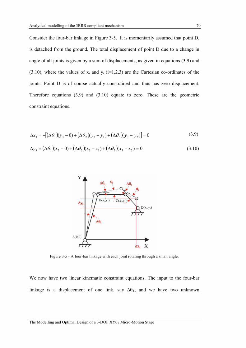
Analytical modelling of the 3RRR compliant mechanism 70
The Modelling and Optimal Design of a 3-DOF XYθZ Micro-Motion Stage
Consider the four-bar linkage in Figure 3-5. It is momentarily assumed that point D,
is detached from the ground. The total displacement of point D due to a change in
angle of all joints is given by a sum of displacements, as given in equations (3.9) and
(3.10), where the values of xi and yi (i=1,2,3) are the Cartesian co-ordinates of the
joints. Point D is of course actually constrained and thus has zero displacement.
Therefore equations (3.9) and (3.10) equate to zero. These are the geometric
constraint equations.
(3.9)
( ) ( ) ( ) 0)()()0( 233132313 =−∆+−∆+−∆=∆ xxxxxy θθθ (3.10)
Figure 3-5 - A four-bar linkage with each joint rotating through a small angle.
We now have two linear kinematic constraint equations. The input to the four-bar
linkage is a displacement of one link, say ∆θ1, and we have two unknown
( ) ( ) ( )[ ] 0)()()0( 233132313 =−∆+−∆+−∆−=∆ yyyyyx θθθ

Analytical modelling of the 3RRR compliant mechanism 71
The Modelling and Optimal Design of a 3-DOF XYθZ Micro-Motion Stage
displacements, ∆θ2 and ∆θ3. These two equations can be solved easily to provide
both ∆θ2 and ∆θ3 as a product of ∆θ1 and a constant.
The total change in angle of link 2 is given by adding the rotation of links 1 and 2,
and the total change in angle of link 3 is given by adding the rotation links 1, 2 and 3,
as given by equations (3.11) and (3.12), respectively.
12212 θθθφ ∆=∆+∆= c (3.11)
133213 θθθθφ ∆=∆+∆+∆= c (3.12)
where c2 and c3 are constants. Equations (3.11) and (3.12) are the kinematic
equations describing the four–bar linkage. As the kinematic equations are linear, the
Jacobian, which is the time derivative of the kinematic equations, is described by the
similar linear equations, as given by equations (3.13) and (3.14).
122 θφ && c= (3.13)
133 θφ && c= (3.14)
3.2.2 Dynamic model
The general form of the dynamic model is given by equation (3.15).
τθθθθθθ =++ )(),()( 111111 KCM &&&& (3.15)

Analytical modelling of the 3RRR compliant mechanism 72
The Modelling and Optimal Design of a 3-DOF XYθZ Micro-Motion Stage
Where M(θ1) is the inertia term, C( 11,θθ & ) is the centripetal term, K(θ1) is the stiffness
term and τ is the forcing term.
To derive the dynamic model the Lagrangian method can be applied. The Lagrangian
equation is given in equation (3.16) below.
τθθθ
=∂∂
+∂∂
−∂∂
111
PKK
dt
d&
(3.16)
Where K is the kinetic energy term and P is the potential energy term.
3.2.2.1 Potential energy
The potential energy of the mechanism is stored in the stiffness of the flexure hinges.
Gravity is ignored in this analysis as it is generally far less significant than the
stiffness of the structure, as link and load masses are generally relatively small. The
bending stiffness of the flexure hinges, Kb, can be calculated using equation (3.1).
The potential energy of the four-bar linkage is given by equation (3.17).
[ ]2
44
2
33
2
22
2
11
24
1 2
1
2
1θθθθθ ∆+∆+∆+∆=∆= ∑
=
kkkkkP i
i
i (3.17)
where k1, k2, k3 and k4, are the stiffnesses of flexure hinges A, B, C and D,
respectively, and the flexure hinge rotations are given by equations (3.18) to (3.20).

Analytical modelling of the 3RRR compliant mechanism 73
The Modelling and Optimal Design of a 3-DOF XYθZ Micro-Motion Stage
( ) 12112122 1 θθθθφθ ∆−=∆−∆=∆−=∆ cc (3.18)
( ) 1231213233 θθθφφθ ∆−=∆−∆=−=∆ cccc (3.19)
1334 θφθ ∆==∆ c (3.20)
Substituting equations (3.18) to (3.20) into equation (3.17) gives the potential energy
as a function of ∆θ1, equation (3.21). All other values are constants and, therefore,
the equation can be represented as in equation (3.22) where Ψ is a constant.
[ ] 2
1
2
34
2
233
2
221 )()1(2
1θ∆+−+−+= ckcckckkP (3.21)
2
12
1θΨ∆=P (3.22)
To calculate the stiffness term of the Lagrangian we take the partial derivative of P,
as given in equation (3.23).
( )( ) 111
1
2
11
1
2
1
1
2
1
2
1
θθθθ
θθ
θ
θ
θΨ∆=−Ψ=
∂
−Ψ∂=
∂
Ψ∆∂=
∂∂
o
oP
(3.23)

Analytical modelling of the 3RRR compliant mechanism 74
The Modelling and Optimal Design of a 3-DOF XYθZ Micro-Motion Stage
3.2.2.2 Kinetic energy
A lumped-mass approximation is used in this model, i.e. the mass of the links is
assumed to be a point mass located at the centre of mass as shown in Figure 3-3. The
kinetic energy of the mechanism is given by equation (3.24).
( )∑=
++=3
1
222
2
1
2
1
i
iiiyixi JVVmK θ& (3.24)
where V is the velocity of the centre of mass of the links, m is the mass of the links
and J is the moment of inertia of the links.
Vx and Vy for each link can be determined using the Jacobian constants, equations
(3.13) and (3.14), and by applying the same approached as was used to generate the
constraint equations, equations (3.9) and (3.10). As all the terms other than link
displacements are constants ∆θ1, ∆θ2 and ∆θ3 can be replaced with 1θ& , 2θ& and 3θ& ,
respectively.
1111 )01( θθ &&xyx VccmV =−= (3.25)
1111 )01( θθ &&xxy VccmV =−−= (3.26)
121212 )2()2( θθθ &&&xyyyyx VcBcmcAcmV =−+−= (3.27)

Analytical modelling of the 3RRR compliant mechanism 75
The Modelling and Optimal Design of a 3-DOF XYθZ Micro-Motion Stage
121212 )2()2( θθθ &&&yxxxxy VcBcmcAcmV =−+−−= (3.28)
)3(133 yyx DcmcV −= θ& (3.29)
)3(133 xxy DcmcV −−= θ& (3.30)
These velocity terms, equations (3.25) to (3.30) can be substituted into the kinetic
energy equation, equation (3.24). The mass moment of inertia of each link, J, which
is dependent on the shape of the link, can also be substituted into the kinetic energy
equation.
If the link is rectangular, with height, h, and width, b, then J is given by equation
(3.31) below.
)(12
1 22
iiii hbmJ += , i=1,2,3 (3.31)
The resulting equation can be written as a function of 1θ& where all other values are
constants, equation (3.32). The kinetic energy equation can thus be represented in the
form of equation (3.33) where Ω is a constant.
( ) ( ) ( )[ ] 2
13
2
3
2
332
2
2
2
221
2
1
2
112
1θ&JVcVcmJVcVcmJVcVcmK yxyxyx ++++++++= (3.32)
2
12
1θ&Ω=K (3.33)

Analytical modelling of the 3RRR compliant mechanism 76
The Modelling and Optimal Design of a 3-DOF XYθZ Micro-Motion Stage
To obtain the Lagrangian terms we take two derivatives. The first is equation (3.34).
11
1
2
1
1
2
1
θθθ
θ
θ&&&
&
&
&Ω=Ω=
∂
Ω∂
=∂∂
dt
d
dt
dK
dt
d (3.34)
The second is equation (3.35).
02
1
1
2
1
1
=∂
Ω∂
=∂∂
θ
θ
θ
&
K (3.35)
Looking at the kinetic energy term it can be seen that this is a function of velocity
only. Therefore the derivative with respect to displacement is zero and there is no
centripetal term. If one considers the nature of this linear model it can be reasoned
why this is the case. The angular motion of each joint is neglected when the small
angle assumption is made. As the motion of each joint is linear no angular centripetal
forces are generated.
Substituting equations (3.23), (3.34) and (3.35) into equation (3.16) gives the total
dynamic model for the four-bar linkage as given in equation (3.36).
τθθ =Ψ+Ω 11&& (3.36)

Analytical modelling of the 3RRR compliant mechanism 77
The Modelling and Optimal Design of a 3-DOF XYθZ Micro-Motion Stage
Thus the dynamic model is given by a linear ordinary differential equation with
constant coefficients.
3.2.3 Comparison of linear model and complete non-linear model
To demonstrate the accuracy of a model derived using the linear-Cartesian method it
was compared to a general non-linear PRBM. The non-linear model was derived for
the four-bar linkage using the Lagrangian method. The details of this model are
given in [Zhang, 1999]. This model has the form given in equation (3.37).
τθθθθθθ =++ )(),()( 111111 KCM &&&& (3.37)
The linear model is far simpler than the general non-linear model, and has the form
given in equation (3.38).
τθθ =∆+∆ 11 linlin KM && (3.38)
To compare both models, the four-bar linkage shown in Figure 3-6 is considered
next. The parameters defining this linkage are given in Table 3-1.

Analytical modelling of the 3RRR compliant mechanism 78
The Modelling and Optimal Design of a 3-DOF XYθZ Micro-Motion Stage
Figure 3-6 – A schematic of the example compliant four-bar linkage.
Four-Bar Linkage Parameter Value
Length - Link 1, Link 2, Link 3, Link 4 (mm) 50, 70, 50, 60
θθθθ1, θθθθ2, θθθθ3, θθθθ4 (°°°°) 90, 89.17, 78.47, 102.35
A(x,y), B(x,y), C(x,y), D(x,y) (mm) (0,0), (0,50), (69.99,48.99), (60, 0)
Mass - Link 1, Link 2, Link 3 (g) 10, 500, 10
K1, K2, K3, K4 (Nm/rad) 40
ττττ1 (Nm) 1.2
Table 3-1 - Example four-bar Linkage Parameters.
3.2.3.1 Kinematics
To compare the kinematics of both models an input angular displacement, ∆θ1 of 1°
was applied to link 1 of both models. The rotational displacements of the other joints,
∆θ2, ∆θ3, and ∆θ4 generated by this input were then calculated.
The linear-Cartesian method was used to calculate the linear kinematic constants, c2
and c3, as defined in equations (3.13) and (3.14). These constants are given below.

Analytical modelling of the 3RRR compliant mechanism 79
The Modelling and Optimal Design of a 3-DOF XYθZ Micro-Motion Stage
c2 = 0.1453 (3.39)
c3 = 1.0176 (3.40)
The values of constants c2 and c3 are substituted into equations (3.18) to (3.20) to
calculate the rotational displacements of the joints. The non-linear model was used to
calculate the same rotational displacements. The results from both models are given
in Table 3-2.
Joint Angle Linear-Cartesian Model
∆∆∆∆θθθθ (°°°°) Non-linear Model
∆∆∆∆θθθθ (°°°°) Difference
(%)
θθθθ1 1 1 0
θθθθ2 -0.8547 -0.8550 0.04
θθθθ3 0.8723 0.8711 0.14
θθθθ4 -1.0176 -1.0160 0.16
Table 3-2 - Angular displacement of joints predicted by linear and non-linear kinematic models.
It can be seen that the linear and non-linear models give very similar results.
3.2.3.2 Dynamics
Using the linear-Cartesian method the dynamic model was derived for the example
four-bar linkage. This is given in equation (3.41) below.
τθθ =+ 11 1.1410014.0 && (3.41)
To compare this linear dynamic model with the non-linear model, a step input torque,
τ1=1.2 Nm, was applied to link 1 of both models. This caused oscillation of the four-
bar linkage with an amplitude of ∆θ1 = 0.97°. The non-linear model inertia term,

Analytical modelling of the 3RRR compliant mechanism 80
The Modelling and Optimal Design of a 3-DOF XYθZ Micro-Motion Stage
M(θ1), centripetal term, ),( 11 θθ &C , and stiffness term, K(θ1), were compared to their
respective counterparts, Mlin, and Klin∆θ1. This comparison was made at the two
extreme positions of the four-bar linkage, i.e. at ∆θ1 = 0° and 0.97° . The parameters
of the dynamic model are shown in Table 3-3.
∆∆∆∆θθθθ 0°°°° 0.97°°°° M 0.0014 0.0014
Mlin 0.0014 0.0014
C 1.22E-04 1.23E-04
K(∆∆∆∆θθθθ) 0 2.396
Klin∆∆∆∆θθθθ 0 2.398
Table 3-3 - Comparison of dynamic model terms for ∆θ1 = 0° and 0.97° .
From these results it is apparent that the non-linear terms do not vary significantly
for this small-scale motion. The inertia terms are identical, the C term is negligible,
and the stiffness terms are nearly identical. This result demonstrates that the ‘linear-
Cartesian’ method is a valid approximation for the PRBM of the four-bar linkage,
with accuracy close to a non-linear PRBM.

Analytical modelling of the 3RRR compliant mechanism 81
The Modelling and Optimal Design of a 3-DOF XYθZ Micro-Motion Stage
3.3 3RRR compliant mechanism
In the previous section the ‘linear-Cartesian’ method was applied to a single loop
micro-motion compliant mechanism. It was demonstrated that the performance of
both the kinematic and the dynamic model are very close to the original non-linear
model. The method is now applied to the multiple loop case of the 3RRR compliant
mechanism, as shown in Figure 3-7 with its PRBM.
Considering the 3RRR mechanism it can be seen that there are three closed loops.
However, as will be demonstrated, only two of these need be considered in order to
determine the kinematics of the mechanism. Three inputs must be defined to
determine the position of the end-effector of the mechanism. The inputs to the
mechanism are the rotations of joints A1, A2 and A3 given by ∆θA1, ∆θA2 and ∆θA3.
Figure 3-7 -Schematic of the 3RRR compliant mechanism and its PRBM.

Analytical modelling of the 3RRR compliant mechanism 82
The Modelling and Optimal Design of a 3-DOF XYθZ Micro-Motion Stage
The geometry of the mechanism is described using the Cartesian coordinates of the
joints. These coordinate values are then used directly in the constraint equations to
give the distance between the end-points of each link and the centres of rotation. The
points describing the joint locations can be defined using a global Cartesian reference
frame of any orientation. The solution for the unknown angular joint displacements
will be the same regardless of the orientation of the reference frame. However, it is
most convenient to describe the joint locations of one linkage, say linkage 2, using
the global reference frame shown in Figures 3-7 and 3-10. The joint locations of
linkage 1 and 3 can then be found by rotating linkage 2 through 120° and 240°,
respectively. The origin of the reference frame describing the joint locations
coincides with the centre of the end-effector.
The geometric parameters used to define the 3RRR linkages are shown in Figure 3-8.
Figure 3-8 - Diagram showing the geometric parameters defining the 3RRR linkages (i=1,2,3).

Analytical modelling of the 3RRR compliant mechanism 83
The Modelling and Optimal Design of a 3-DOF XYθZ Micro-Motion Stage
3.3.1 Kinematic model
The kinematic constraint equations for loop 1 are:
0)(
)()()()()1(
222
222121121121
=−∆+
−∆+−∆+−∆+−∆=∆
yyB
yyCyycyyByyA
BA
CACABAAAloopx
θ
θθθθ
(3.42)
0))()(
)()()(()1(
222222
121121121
=−∆+−∆
+−∆+−∆+−∆−=∆
xxBxxC
xxcxxBxxA
BACA
CABAAAloopy
θθ
θθθ (3.43)
The kinematic constraint equations for loop 2 are:
0)(
)()()()()2(
333
333131131131
=−∆+
−∆+−∆+−∆+−∆=∆
yyB
yyCyycyyByyA
BA
CACABAAAloopx
θ
θθθθ
(3.44)
0))(
)()()()(()2(
333
333131131131
=−∆+
−∆+−∆+−∆+−∆−=∆
xxB
xxCxxcxxBxxA
BA
CACABAAAloopy
θ
θθθθ
(3.45)
Inputs to the mechanism are ∆θA1, ∆θA2 and ∆θA3, while ∆θB2 and ∆θB2 are given by
equations (3.46) and (3.47) respectively.
)( 211122 CCBAAB θθθθθθ ∆+∆+∆+∆−∆=∆ (3.46)
)( 311133 CCBAAB θθθθθθ ∆+∆+∆+∆−∆=∆ (3.47)
Equations (3.46) and (3.47) can be substituted into the four loop equations, equations
(3.42) to (3.45). There are now four unknowns, ∆θB1, ∆θC1, ∆θC2 and ∆θC3.
Therefore, the four linear equations can be solved simultaneously to find the four

Analytical modelling of the 3RRR compliant mechanism 84
The Modelling and Optimal Design of a 3-DOF XYθZ Micro-Motion Stage
unknowns. Each displacement is given as a function of the 3 input rotations ∆θA1,
∆θA2 and ∆θA3.
Furthermore the input rotations ∆θA1, ∆θA2 and ∆θA3 are given by equation (3.48).
o
iAi
R
L∆−=∆θ , i = 1,2,3 (3.48)
where ∆Li is the displacement of the ith piezo-actuator and Ro is described in Figure
3-8. In this model it is assumed that all of the elongation of the piezo-actuators is
transferred to the compliant mechanism. However, in later Chapters it will be
established that in the real system this may not be the case.
The kinematics of the end-effector motion can be calculated using equations (3.49) to
(3.51). The subscript ‘Z’ in equation 3.51 refers to the Z-axis, which is perpendicular
to the X-Y plane.
)0()0()0( 111111 ycyByA CBAX −∆+−∆+−∆= θθθ (3.49)
))0()0()0(( 111111 xcxBxA CBAY −∆+−∆+−∆−= θθθ (3.50)
1111 CBACZ θθθφθ ∆+∆+∆== (3.51)
The resulting kinematics is described by a 3x3 matrix of constants, which is
multiplied by the input piezo-actuator displacement to give the end-effector motion,
as given in equation (3.52).

Analytical modelling of the 3RRR compliant mechanism 85
The Modelling and Optimal Design of a 3-DOF XYθZ Micro-Motion Stage
∆
∆
∆
=
∆
∆
∆
3
2
1
333231
232221
131211
L
L
L
JJJ
JJJ
JJJ
Y
X
Zθ (3.52)
The parametric values of these nine constants are given in Appendix A.1. The
Jacobian is given by the same constant matrix.
3.3.2 Dynamic model
The dynamic model is derived using the same approach, using the Lagrangian
method, as described in the four-bar case. However, in this case partial derivatives
are taken of kinetic and potential energy with respect to three piezo-actuator
displacements and velocities, L1, L2 and L3, and 1L& , 2L
& , and 3L& . There are also three
input forces F1, F2 and F3, giving the Lagrangian in equation (3.53).
=∂∂
+∂∂
−∂∂
3
2
1
F
F
F
L
P
L
K
L
K
dt
d
iii&
, i=1,2,3 (3.53)
The potential energy term is given by equation (3.54).
∆+∆+∆= ∑∑∑
===
23
1
23
1
23
12
1Cn
n
nBj
j
jAi
i
i kkkP θθθ (3.54)

Analytical modelling of the 3RRR compliant mechanism 86
The Modelling and Optimal Design of a 3-DOF XYθZ Micro-Motion Stage
where the k terms are the flexure hinge bending stiffnesses as given by equation (3.1)
and the ∆θ terms are the flexure hinge rotations found using equations (3.42) to
(3.48).
Calculating the total potential energy results in an equation of the form given in
equation (3.55)
323121
2
3
2
2
2
1 LLLLLLLLLP βββααα +++++= (3.55)
where α and β are constants. They are discussed further in Appendix A.2. Taking the
partial derivatives of the potential energy with respect to the piezo-actuator input
displacement leads to equation (3.56).
=∂∂
3
2
1
2
2
2
L
L
L
L
P
i αβββαβ
ββα
(3.56)
The kinetic energy is given by equation (3.57).

Analytical modelling of the 3RRR compliant mechanism 87
The Modelling and Optimal Design of a 3-DOF XYθZ Micro-Motion Stage
( )
( ) ( )[ ]
+++++
+++
=∑=
3
1
222222
222
2
1
i
BCiBCiBCiyBCixBCiABiABiABiyABixABi
eeeeeeyeexee
JVVmJVVm
JVVm
Kθθ
θ
&&
&
(3.57)
Where the subscript ‘ee’ refers to the end-effector, ‘AB’ refers to link AB and ‘BC’
refers to link BC.
The end-effector velocities, Veex and Veey, are given directly by the Jacobian, while
the moment of inertia for a thin triangle is given by equation (3.58).
2
9
1eeeeee hmJ = (3.58)
In this equation mee is the end-effector mass and hee is the height of the triangle.
The velocity and moment of inertia of link ABi (i=1,2,3) is given by equations (3.59)-
( 3.61).
)( iyiyAiABix AcmABV −=θ& (3.59)
)( ixixAiABiy AcmABV −−= θ& (3.60)
)(12
1 22
ABiABiABiABi hbmJ += (3.61)

Analytical modelling of the 3RRR compliant mechanism 88
The Modelling and Optimal Design of a 3-DOF XYθZ Micro-Motion Stage
The velocity and moment of inertia of link BCi, i=1,2,3 is given by equations (3.62)-
(3.64).
)()(.
iyiyBiiyiyAiBCix BcmBCAcmBCV −+−= θθ& (3.62)
)()(.
ixixBiixixAiBCiy BcmBCAcmBCV −+−−= θθ& (3.63)
)(12
1 22
BCiBCiBCiBCi hbmJ += (3.64)
All angular velocities, θ& , are functions of 1L& , 2L
& , and 3L& . Calculating the total
kinetic energy results in an equation of the form given in equation (3.65).
323121
2
3
2
2
2
1 LLLLLLLLLK &&&&&&&&& σσσψψψ +++++= (3.65)
where ψ and σ are constants. They are discussed further in Appendix A.2.
To obtain the Lagrangian terms two derivatives are taken. The first is equation (3.66)
below.
=∂∂
3
2
1
1 2
2
2
L
L
LK
dt
d
&&
&&
&&
&
ψσσσψσσσψ
θ (3.66)

Analytical modelling of the 3RRR compliant mechanism 89
The Modelling and Optimal Design of a 3-DOF XYθZ Micro-Motion Stage
The second is equation (3.67) below.
0=∂∂
iL
K (3.67)
Substituting equations (3.56), (3.66) and (3.67) into equation (3.53) gives the total
dynamic model for the 3RRR mechanism as equation (3.68).
=
+
3
2
1
3
2
1
3
2
1
2
2
2
2
2
2
F
F
F
L
L
L
L
L
L
αβββαβββα
ψσσσψσσσψ
&&
&&
&&
(3.68)
where ψ, σ, α and β are constants.

Analytical modelling of the 3RRR compliant mechanism 90
The Modelling and Optimal Design of a 3-DOF XYθZ Micro-Motion Stage
3.4 Kinematic and dynamic models of the first prototype
A prototype of the 3RRR compliant mechanism was built, as shown in Figure 3-9.
Figure 3-9 - Prototype of the 3RRR compliant mechanism.
The topology of this compliant mechanism is the same as the mechanism presented
by Zhang et al. (2002). This was used for experimental verification as will be
discussed in Chapter 8. The parameters of this compliant mechanism are given in
Table 3-4. The end-effector was modelled as a triangle, as shown in Figures 3-7 and
3-10. The parameters defining this triangle are shown in Figure 3-10; the thickness of
the triangle is tend-effector. The material used for both the compliant mechanism and
end-effector is aluminium.
3RRR Compliant Mechanism
Parameter Value
A2(x,y), B2 (x,y), C2 (x,y) (mm) (28, 10), (23, 27), (12, 27)
T (mm) 0.94
R (mm) 1.5
B (mm) 11.7
Ro (mm) 3.5
cmAB2(x,y), cmBC2(x,y) (mm) (28, 21), (17.5, 27)

Analytical modelling of the 3RRR compliant mechanism 91
The Modelling and Optimal Design of a 3-DOF XYθZ Micro-Motion Stage
bAB2, hAB2 (mm) 22, 7
bBC2, hBC2 (mm) 10, 8
Triangular End-Effector
Parameters Value
bee (mm) 51.18
hee (mm) 44.32
tend-effector (mm) 10
Material Properties of 7075-T6
Aluminium Value
E (MPa) 72
ρρρρ (Kg/m3) 2810
Table 3-4 – Parameters of 3RRR compliant mechanism prototype.
These parameters were substitute into the analytical model to derive the kinematic
model and dynamic model.
3.4.1 Kinematics of The first prototype
The resulting kinematic model matrix is given in equation (3.69) below.
∆
∆
∆
−−−
=
∆
∆
∆
3
2
1
96.5996.5996.59
2.804- 0.000 2.804
1.619-3.2381.619-
L
L
L
Y
X
Zθ (3.69)

Analytical modelling of the 3RRR compliant mechanism 92
The Modelling and Optimal Design of a 3-DOF XYθZ Micro-Motion Stage
Figure 3-10 - Schematic showing the coordinate reference frame used to define the joint locations in
the ‘linear-Cartesian’ method and the reference frame used by Zou (2000). The triangular end-effector
parameters are also defined.
This result can be compared with the constant kinematics derived for this compliant
mechanism by Zou (2000) and Yong et al. (2004). Those results used a different
reference frame to define the mechanism, as shown in Figure 3-9. The matrix must
be rotated by θo to give the Jacobian in the same reference frame. The rotated
Jacobian is given in equation (3.70) below.
∆
∆
∆
−−−
−−
−
=
∆
∆
∆
3
2
1
96.5996.5996.59
618.2960.2341.0
905.1315.1220.3
L
L
L
Y
X
Zθ (3.70)
This result agrees with the results presented by both Zou (2000) and Yong et al
(2004). Both Zou and Yong based their models upon the PRBM, but used different
methods to derive the kinematics.

Analytical modelling of the 3RRR compliant mechanism 93
The Modelling and Optimal Design of a 3-DOF XYθZ Micro-Motion Stage
In Chapter 4 the Jacobian will be derived using different modelling methods and
compared to analytically derived Jacobian. Experimental verification will be
discussed in Chapter 8.
3.4.2 Dynamics of the prototype 3RRR compliant mechanism
The resulting dynamic model is given in equation (3.71) below.
=
+
3
2
1
3
2
1
3
2
1
3.07e77.676e57.676e5
7.676e53.07e77.676e5
7.676e57.676e53.07e7
0.9000.305-0.305-
0.305-0.9000.305-
0.305-0.305- 0.900
F
F
F
L
L
L
L
L
L
&&
&&
&&
(3.71)
It can be noted that both the inertia and stiffness matrix are symmetrical, which is
expected due to the symmetrical design of the compliant mechanism.
3.4.2.1 Natural frequencies of the prototype 3RRR compliant mechanism
The natural frequency of a system can be calculated from the mass and stiffness
terms given by the dynamic model using the following eigenvalue equation.
02 =− MK ω (3.72)
The positive square roots of the solutions of the above equation are the natural
frequencies of the system.

Analytical modelling of the 3RRR compliant mechanism 94
The Modelling and Optimal Design of a 3-DOF XYθZ Micro-Motion Stage
For the 3RRR compliant mechanism the natural frequencies are estimated
theoretically from the linear dynamic model, which has the general form given in
equation (3.73).
=
+
0
0
0
3
2
1
3
2
1
L
L
L
kkk
kkk
kkk
L
L
L
mmm
mmm
mmm
zii
izi
iiz
zii
izi
iiz
&&
&&
&&
(3.73)
This can also be given in the form of equation (3.74).
[ ][ ] [ ][ ] [ ]0=+ LKLM && (3.74)
where M and K are the inertia and stiffness matrices, respectively, and L is the input
displacement vector. The Singular Value Decomposition (SVD) function in Matlab
was used, as shown in equation (3.75), to determine the frequencies of the modes of
vibration.
=M
KsvdVSU ],,[ (3.75)
This function returns a diagonal matrix, S, as shown in equation (3.76).
=2
3
2
2
2
1
00
00
00
n
n
n
S
ωω
ω (3.76)

Analytical modelling of the 3RRR compliant mechanism 95
The Modelling and Optimal Design of a 3-DOF XYθZ Micro-Motion Stage
The natural frequencies in Hz are then given by equation (3.77).
π
ωω
2)(
2
ni
ni Hz = (i=1,2,3) (3.77)
The translational modes are given by ωn2 and ωn3, while the rotational mode is given
by ωn1. The natural frequencies for the prototype 3RRR compliant mechanism are
given in Table 3-5.
Mode Numerical PRBM
ωωωωn 1st translation 793
2nd translation 793
1st rotation 1678
Table 3-5 - The natural frequencies predicted by the analytical PRBM for the prototype 3RRR
compliant mechanism.
3.5 Discussion
The ‘linear-Cartesian’ method has been demonstrated to effectively derive the
constant-Jacobian kinematic model and the linear dynamic model of the 3RRR
compliant mechanism. The Jacobian derived in this study agrees with the Jacobians
derived by other researchers. In Chapter 4 the kinematic model and dynamic model
derived in this study will be compared to a number of models derived using other
methods. In Chapter 8 experimental results will be presented to validate the models.

97
Chapter
4 Numerical modelling of the 3RRR compliant mechanism
In Chapter 3 an analytical pseudo-rigid-body model (PRBM) of the 3RRR compliant
mechanism was presented. The PRBM of a planar compliant mechanism models a
flexure hinge, as shown in Figure 4-1(a), as a revolute joint with torsional spring,
joined by rigid links, as shown in Figure 4-1(b). Thus the flexure hinge has only one
degree-of-freedom (DOF), rotation about the z-axis. The stiffness of this joint is
given by Kb. This model has limited accuracy for predicting the kinematic and
dynamic behaviour of a compliant mechanism. As discussed in Chapter 2, it has been
observed by other researchers that the flexure hinges do not only undergo revolute
motion but there is also translational compliance in the hinge and so the links can
translate relative to each other. To model this multi-DOF behaviour using an
analytical model is complex. Therefore, it is proposed to use a numerical modelling
method using a Finite-Element-Analysis (FEA) package, such as ANSYS.

Numerical modelling of the 3RRR compliant mechanism 98
The Modelling and Optimal Design of a 3-DOF XYθZ Micro-Motion Stage
Figure 4-1 - (a) A flexure hinge, (b) a 1-DOF PRBM model and (c) a 3-DOF model.
4.1 Finite element models
In this study only planar compliant mechanisms are considered and it has been
ensured that the compliant mechanisms are made from material sufficiently thick to
support the z-directional load such that out-of-plane displacements are insignificant.
Therefore, out-of-plane displacements can be ignored so that only translations and
rotation in the x-y plane need be considered.
FEA models have been commonly used to model compliant mechanisms and have
the potential to provide the most accurate prediction of the kinematic and dynamic
behaviour of the compliant mechanism. A two-dimensional (2-D) Finite-Element-
Model (FEM) is well suited to model planar mechanisms with uniform thickness,
when there are no significant out-of-plane forces and motions. In this chapter, a 2-D
FEM is presented to model the compliant mechanisms. However, to construct, mesh
and solve a 2-D FEM is more time consuming and computationally expensive than a

Numerical modelling of the 3RRR compliant mechanism 99
The Modelling and Optimal Design of a 3-DOF XYθZ Micro-Motion Stage
PRBM. If multiple models need to be generated, say, for the purpose of a parametric
study or optimisation, then the problem of computational expense is compounded.
It is highly desirable to find an alternative modelling method that can provide greater
accuracy than a PRBM but which is computationally simple enough to be efficient
for optimisation. This chapter also presents a numerical method to model a flexure
hinge compliant mechanism with greater accuracy than a PRBM, while being far
simpler than a 2-D FEM. The method is similar to the PRBM approach but models
the flexure hinge as a joint with 3-DOF – rotation about the z-axis, and translation in
x- and y-axis, as shown in Figure 4-1(c). The stiffness of this joint is described using
three terms Kb, Kx and Ky, and also incorporates link compliance. This method has
been termed, by the author, the Simple-Compliant-Hinge Model (SCHM).
In this chapter the FEM, SCHM and PRBM methods will all be compared. Models of
a single flexure-hinge, a compliant 4-bar linkage and a 3RRR compliant mechanism
are constructed using each method. The kinematic and/or dynamic model predictions
are then compared. The kinematics can be compared by providing a displacement at
the input location of the mechanism and then measuring the displacement at the
output location. The dynamics can be compared firstly by determining the stiffness
of the mechanism and secondly by determining the natural frequency of the
mechanism. All the models have been created in the ANSYS environment. The
PRBM constructed using ANSYS will be shown to be the same as the analytically
derived model.

Numerical modelling of the 3RRR compliant mechanism 100
The Modelling and Optimal Design of a 3-DOF XYθZ Micro-Motion Stage
4.1.1 2-D Finite-Element-Model (FEM)
The 2-D FEM were constructed in ANSYS using a 2-D analysis. The models used 8-
node, two-dimensional plane elements (PLANE82) with 2-DOF on each node, which
are translations in the x- and y- directions. Plane-stress elements with thickness are
used, as this results in a 5-10% under estimation of stiffness in the x-, y- and θz
direction, instead of the possibility of a greater over estimation [Schotborgh et al.,
2005].
A free mesh was used and to ensure a suitable mesh size a number of analysis were
made using different mesh sizes. It was then checked that the output was the same
each time confirming that the choice of mesh was fine enough and not causing
erroneous results. The choice of loading was also carefully checked to ensure that, if
point loads were used, they did not cause significant local deformation of the mesh.
In some cases it was found that the load should be applied as a pressure over an area
to avoid excessive local deformation within the mesh. Where ever a point load was
used, the displacement needed to be measured at a point outside of the area of local
deformation.
4.1.2 Simple-Compliant-Hinge Model (SCHM)
ANSYS provides the tools to construct simple models using beam, joint and spring
elements. Using these types of elements it is possible to construct a PRBM type
model but to incorporate more complex joint behaviour than purely revolute motion.
Such a model will be discussed here. The flexure hinge is modelled using two

Numerical modelling of the 3RRR compliant mechanism 101
The Modelling and Optimal Design of a 3-DOF XYθZ Micro-Motion Stage
coincident nodes joined by two elements - COMBIN7 and COMBIN14. A schematic
is shown in Figure 4-2.
Figure 4-2- A 3-DOF model of a flexure hinge using ANSYS elements.
COMBIN7 provides a three-dimensional revolute joint with joint flexibility. The
nodes (I, J) are defined to have six degrees of freedom. The DOF are defined by a
local coordinate system which is affixed to each node. In this model the coordinate
systems of the two coincident nodes have the same orientation. All of these DOF are
intended to be constrained with a certain level of flexibility. This level of flexibility
is defined by four input stiffnesses; K1 is the translational stiffness in the x-y plane,
K2 is the stiffness in the z-direction; K3 is the rotational stiffness about the x- and y-
axis; and K4 is the rotational stiffness in the primary degree of freedom, rotation
about the z-axis, ROTZ. The dynamic behaviour of ROTZ can also be controlled
using other input values, but this is unnecessary for our model. Whenever the link is

Numerical modelling of the 3RRR compliant mechanism 102
The Modelling and Optimal Design of a 3-DOF XYθZ Micro-Motion Stage
designed to have no compliance in one of these axes the stiffness is set to 1018
.
Theoretically, to ensure no compliance the stiffness should be infinite, but this is
impossible to compute. The stiffness value chosen, 1018
, is the largest value that can
be used without causing computational problems in ANSYS. For the 3-DOF flexure
hinge model the out-of-plane stiffness, K2 and K3, are set to 1018
. COMBIN7
provides the same translational stiffness in both the x- and y-axis of the x-y plane.
However, the real flexure hinge has different stiffness in the x- and y-axes.
Therefore, the COMBIN7 element by itself can not adequately model the flexure
hinge. To provide a more accurate model a COMBIN14 element was added. This
element is used to describe a linear spring that gives an extra stiffness, K14, in the x-
direction. The x-and y-axis stiffness can now be set individually to accurately
represent the translational compliance of the flexure hinge. The 3-DOF hinge
stiffness are given by Kx=K1+K14, Ky=K1 and Kb=K4. The flexure hinges are joined
by links that are represented using BEAM3 elements. The material and geometric
properties of the links can be described using this element so that the link compliance
behaviour is modelled. This flexure hinge model has been termed by the author the
Simple-Compliant-Hinge-Model (SCHM).
4.1.2.1 Stiffness terms
Paros and Weisbord developed analytical equations to predict the stiffness of the
flexure hinges in different DOF. These equations have been adopted by researchers
as the standard analytical equations. Wu and Lobontiu developed simpler equations
that produced the same prediction as Paros and Weisbord for hinge stiffness. In this
thesis the equations of Paros-Weisbord, Wu and Lobontiu are all used depending on

Numerical modelling of the 3RRR compliant mechanism 103
The Modelling and Optimal Design of a 3-DOF XYθZ Micro-Motion Stage
which equation is the simplest and most appropriate. Figure 4-3 shows the definition
of forces, moments, linear displacements and rotations used by Paros-Weisbord, Wu
and Lobontiu to define the flexure hinge compliance terms. The corresponding
stiffness terms are simply the reciprocal values of the compliance terms.
Figure 4-3- Schematic of a flexure hinge showing definition of dimensions and forces.
The equations given by Wu, equations (4.1) and (4.2) are used directly to give the
stiffness terms Kb and Kx, in the SCHM.
( )( )( )
( )( )
+
+
++
++
++== 14arctan
14
1212
1412
146212125
4
2
23
2s
s
ss
ss
sss
EbRMK z
z
b
α (4.1)
( )
−+
+
+=
∆=
214arctan
14
12211 πs
s
s
EbF
x
K xx
(4.2)
where s = R/t

Numerical modelling of the 3RRR compliant mechanism 104
The Modelling and Optimal Design of a 3-DOF XYθZ Micro-Motion Stage
However, Ky must be carefully determined so that it is suitable for the SCHM. As
will be shown below a modification of the Paros-Weisbord equation gives an
appropriate compliance value for the model. It should be noted from Figure 4-3 that
Fy is applied at the edge of the hinge, a distance of R from the centre of rotation of
the hinge. Therefore, the compliance term yF
y∆refers to a point R from the centre of
rotation. The ∆y of this point will consist of a pure y-direction translation, ∆yt and a
rotational term αzR as shown in Figure 4-4.
Figure 4-4- Schematic of flexure hinge and SCHM under load, showing translational displacement of
hinge centre.
∆y is given by equation (4.3).
Ryy zt α+∆=∆ (4.3)
For the SCHM only the compliance term that defines the y-direction translation,
y
t
F
y∆, is needed, as the compliance is between two coincident nodes located at the
Numerical modelling of the 3RRR compliant mechanism 105
The Modelling and Optimal Design of a 3-DOF XYθZ Micro-Motion Stage
centre of rotation of the hinge. The Paros-Weisbord equation for yF
y∆ in bending for
a right-circular hinge is given by equation (4.4).
(4.4)
where β = t/2R
The rotation compliance due to Fy is given by equation (4.5).
z
z
y
z
MR
F
αα= (4.5)
Therefore, the ∆y due to rotation, αz, at distance R from the centre of rotation is
given by equation (4.6).
=
∆
z
z
y MR
F
yz
αα 2 (4.6)
Subtracting this term from equation (4.4) gives the y-direction translation of the
centre of the hinge as given by equation (4.7).
( )
( )( )( )
( ) ( )( )
−+
+
+−
+
+
+
+++
+−
+−
− πββ
ββ
β
ββ
β
ββββ
βα
2tan
2
12
2
14
1
2
12
1
1
2
3
1
2322
2
2
2
EbMR
z
z=∆
yF
y

Numerical modelling of the 3RRR compliant mechanism 106
The Modelling and Optimal Design of a 3-DOF XYθZ Micro-Motion Stage
(4.7)
The shear compliance of the hinge is also included when calculating Ky. The
equation derived by Paros-Weisbord is given in equation (4.8).
( )
xy
s
F
x
G
E
GbF
y ∆=
+
+
++−=
∆ −
ββ
ββ
βπ 2tan
2
12
2
1 1
2 (4.8)
where G is the shear modulus.
Wu derived an equation that is the equivalent of the Paros-Weisbord equation, as
given in equation (4.9).
( )xy
s
F
x
G
Es
s
s
GbF
y ∆=
−+
+
+=
∆
214arctan
14
1221 π (4.9)
However, Lobontiu derived a different equation for shear compliance, as given in
equation (4.10).
xy
s
F
x
G
E
F
y ∆=
∆ α (4.10)
( )
( )( )( )
( ) ( )( )
−+
+
+−
+
+
+
+++
+−
+−
− πββ
ββ
β
ββ
β
ββββ
β
2tan
2
12
2
14
1
2
12
1
1
2
3
1
2322
2
2
Eb=
∆
y
t
F
y

Numerical modelling of the 3RRR compliant mechanism 107
The Modelling and Optimal Design of a 3-DOF XYθZ Micro-Motion Stage
where α is a correction factor that depends on the shape of the cross section. For the
rectangular cross section of the single axis circular flexure hinge α =3/2 has been
chosen, as given by [Timoshenko, 1940]. It was unclear which shear compliance was
more accurate and so this needed to be studied to determine which should be used.
Finally, Ky is given by equation (4.11).
y
s
y
ty
F
y
F
yK
∆+
∆=
1 (4.11)
4.1.3 Pseudo-Rigid-Body-Model (PRBM)
A PRBM can easily be constructed in ANSYS. A thus defined PRBM can be used to
check the numerical results of ANSYS. This is easier than a direct comparison with a
standalone analytical model as everything can be done in ANSYS. In the ANSYS
models the revolute joint element COMBIN7 is defined by stiffness in all 6-DOF. A
pure PRBM has infinite stiffness in all DOF except for rotation about the z-axis. In
the ANSYS model the PRBM was modelled by setting all stiffness values except the
z-axis rotation to be 1018
. This value was large enough to consider any translational
stiffness to be insignificant. The z-axis rotation stiffness is given by Kb. To ensure
that the link deflections are negligible the BEAM3 elements are given a Young’s
modulus 104 GPa.

Numerical modelling of the 3RRR compliant mechanism 108
The Modelling and Optimal Design of a 3-DOF XYθZ Micro-Motion Stage
4.2 Flexure-hinge model
In the first investigation a single flexure-hinge was considered. The flexure-hinge is
fixed at one end and connected to a rigid link at the other. Loads Fx and Fy in the x-
and y- axis, of 1N, are applied independently to the end of the rigid link and the
displacement and rotation of the end of the link is determined. Load Fx causes
displacement ∆x, while load Fy causes displacement ∆y and ∆θz. Figure 4-5(a)
shows the 2-D FEM and Figure 4-5(b) shows the equivalent SCHM / PRBM.
Figure 4-5- 2-D FEM model and a SCHM/PRBM of a single flexure hinge and beam.
The SCHM and PRBM models look the same but the stiffness terms are different.
The load in the y-direction is applied to a single node located at the end of the beam,
which did not cause significant local deformation of the mesh. However, when the
x-direction load is applied as a point load significant local deformation of the mesh is
caused. Therefore, the 1N load was applied as a pressure across the end of the beam.
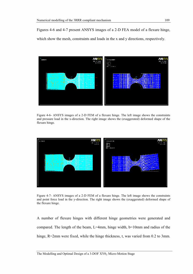
Numerical modelling of the 3RRR compliant mechanism 109
The Modelling and Optimal Design of a 3-DOF XYθZ Micro-Motion Stage
Figures 4-6 and 4-7 present ANSYS images of a 2-D FEA model of a flexure hinge,
which show the mesh, constraints and loads in the x and y directions, respectively.
Figure 4-6- ANSYS images of a 2-D FEM of a flexure hinge. The left image shows the constraints
and pressure load in the x-direction. The right image shows the (exaggerated) deformed shape of the
flexure hinge.
Figure 4-7- ANSYS images of a 2-D FEM of a flexure hinge. The left image shows the constraints
and point force load in the y-direction. The right image shows the (exaggerated) deformed shape of
the flexure hinge.
A number of flexure hinges with different hinge geometries were generated and
compared. The length of the beam, L=4mm, hinge width, b=10mm and radius of the
hinge, R=2mm were fixed, while the hinge thickness, t, was varied from 0.2 to 3mm.

Numerical modelling of the 3RRR compliant mechanism 110
The Modelling and Optimal Design of a 3-DOF XYθZ Micro-Motion Stage
The Young’s modulus of the material was 72GPa. The displacements produced by
the loads for each hinge geometry are given in Tables 4-1 and 4-2. Table 4-1 gives a
comparison of the 2-D FEM and the SCHM. Table 4-2 gives a comparison of the 2-
D FEM and the PRBM. As shown in equations (4.9) and (4.10) there is a choice of
two possible shear compliance terms, Paros-Weisbord (PW) and Lobontiu (LOB),
that can be used in calculating Ky. It was not known which of these would be more
accurate and therefore both were applied and the results compared, as shown in
Table 4-1.
2-D FEM SCHM % diff.
t(mm) ∆∆∆∆x
Fx=1N
∆∆∆∆y Fy =1N
∆∆∆∆θθθθz Fy =1N
∆∆∆∆x Fx=1N
∆∆∆∆y (PW) Fy =1N
∆∆∆∆y (LOB) Fy =1N
∆∆∆∆θθθθz Fy =1N
∆∆∆∆x
∆∆∆∆y (PW)
∆∆∆∆y LOB
∆∆∆∆θθθθz
0.2 1.33e-8 5.75e-5 9.55e-3 1.27e-8 5.54e-5 5.54e-5 9.20e-3 4.8 3.7 3.7 3.7
0.5 8.08e-9 6.02e-6 9.94e-4 7.75e-9 5.54e-6 5.55e-6 9.15e-4 4 7.9 7.8 7.9
1 5.47e-9 1.10e-6 1.80e-4 5.27e-9 9.66e-7 9.70e-7 1.58e-4 3.7 12.3 11.9 12.3
1.5 4.20e-9 4.07e-7 6.60e-5 4.16e-9 3.48e-7 3.51e-7 5.66e-5 1 14.6 13.8 14.3
2 3.49e-9 2.01e-7 3.22e-5 3.49e-9 1.69e-7 1.71e-7 2.72e-5 -0.2 16.1 14.8 15.3
2.5 2.99e-9 1.16e-7 1.82e-5 3.04e-9 9.66e-8 9.87e-8 1.55e-5 -1.7 16.5 14.6 14.9
3 2.66e-9 7.44e-8 1.14e-5 2.70e-9 6.13e-8 6.31e-8 9.72e-6 -1.4 17.6 15.1 14.9
Table 4-1- Comparison of 2-D FEM and SCHM of single flexure hinge, and the percentage relative
difference compared to the 2-D FEM. For these hinges, R=2mm, b =10mm, E=72GPa.
2-D FEM PRBM % diff.
t(mm)
∆∆∆∆x Fx=1N
∆∆∆∆y Fy =1N
∆∆∆∆θθθθz Fy =1N
∆∆∆∆x Fx=1N
∆∆∆∆y Fy =1N
∆∆∆∆θθθθz Fy =1N ∆∆∆∆x ∆∆∆∆y ∆∆∆∆θθθθz
0.2 1.33e-8 5.75e-5 9.55e-3 0.0 5.52e-5 9.19e-3 N/A 4.1 3.7
0.5 8.08e-9 6.02e-6 9.94e-4 0.0 5.47e-6 9.12e-4 N/A 9.0 8.2
1 5.47e-9 1.10e-6 1.80e-4 0.0 9.36e-7 1.56e-4 N/A 15.1 13.6
1.5 4.20e-9 4.07e-7 6.60e-5 0.0 3.29e-7 5.48e-5 N/A 19.3 17.0
2 3.49e-9 2.01e-7 3.22e-5 0.0 1.55e-7 2.59e-5 N/A 22.9 19.6
2.5 2.99e-9 1.16e-7 1.82e-5 0.0 8.61e-8 1.44e-5 N/A 25.5 21.0
3 2.66e-9 7.44e-8 1.14e-5 0.0 5.31e-8 8.84e-6 N/A 28.7 22.6
Table 4-2- Comparison of 2-D FEM and PRBM of single flexure hinge, and the percentage relative
difference compared to the 2-D FEM. For these hinges, R=2mm, b =10mm, E=72GPa.

Numerical modelling of the 3RRR compliant mechanism 111
The Modelling and Optimal Design of a 3-DOF XYθZ Micro-Motion Stage
From Table 4-1 it can be seen that the relative difference between the SCHM and the
2-D FEM varies significantly depending on the flexure hinge thickness. The greatest
relative difference is observed in the rotation of the hinge ∆θz, which increases as the
hinge thickness, t, increases. The ∆θz directly affects the ∆y result. It can also be
seen that the Lobontiu shear compliance term gives a value of Ky closer to the 2-D
FEM than the Paros-Weisbord term. Assuming that the 2-D FEM gives an accurate
prediction, these results suggest that the SCHM effectively models the flexure hinge
behaviour. But, of course, the SCHM accuracy will be limited by the accuracy of the
analytical equations, which are more accurate for some hinge geometries than for
others.
It can also be seen that the SCHM is more accurate than the PRBM, particularly as t
increases. For the thinnest hinge thickness, t=0.2mm, the PRBM is relatively
accurate in predicting ∆y and ∆θz although it gives no indication of ∆x. This
indicates that for this thin hinge, and particular y-direction load case, the hinge gives
close to purely revolute motion. Therefore, this suggests that the PRBM usefulness
will be limited to certain cases, where the hinge design gives close to revolute motion
and the loading is such that ∆x is relatively insignificant. For these cases the PRBM
may be able to offer appropriate accuracy. However, for general cases, where the
hinge design may not give close to revolute motion and the loading causes significant
∆x, the PRBM will be less accurate, and thus less useful.

Numerical modelling of the 3RRR compliant mechanism 112
The Modelling and Optimal Design of a 3-DOF XYθZ Micro-Motion Stage
4.3 Four-bar linkage
4.3.1 Stiffness
A four-bar linkage, as shown in Figure 4-8, has been modelled using the 2-D FEM,
SCHM and PRBM. Input loads are applied in the x and y directions and the output
displacement of the output link is determined. From these results the stiffness of the
structure in the x and y direction is calculated.
Figure 4-8- 2-D FEM and SCHM / PRBM of a four-bar linkage.
The other model parameters are:
b=5mm
E=72GPa
G=27GPa
υ=0.33
where b is the mechanism thickness and υ is Poisson’s Ratio. The loads Fx and Fy are
applied as point loads. This causes some local deformation of the FEM mesh,

Numerical modelling of the 3RRR compliant mechanism 113
The Modelling and Optimal Design of a 3-DOF XYθZ Micro-Motion Stage
particularly for Fy. Therefore, the displacement of the output link is taken from a
node some distance from the force application node. It can be seen in Figure 4-9(a)
that the 2-D FEM predicts that deflection of the link contributes significantly to the
y-direction displacement. This suggests that, in this case, it is important for the
SCHM beam elements to accurately model the compliance of the links. The x-
direction load causes relatively little deformation of the links, as can be seen in
Figure 4-9(b), and so modelling the link compliance is not as important for this load
case.
(a) (b)
Figure 4-9- ANSYS image showing the deformed mesh, constraints and loads applied to the four-bar
FEM.
The accuracy of the flexure hinge stiffness prediction has a significant effect on the
model performance. The SCHM models use values for Kx, Ky and Kb calculated
using the analytical equations presented by Paros-Weisbord, Wu and Lobontiu. The
values given by these equations, KAnalytical are shown in Table 4-3. A 2-D finite-
element-analysis (FEA) of this hinge geometry was conducted and these values,
KFEA, are also shown in Table 4-3. The percentage error between the analytical
equations and the FEA is also given in Table 4-3. It can be seen that there is a

Numerical modelling of the 3RRR compliant mechanism 114
The Modelling and Optimal Design of a 3-DOF XYθZ Micro-Motion Stage
significant difference in Kb, Kx and Ky predicted by these two methods. Kb and Kx
were calculated using equations (4.1) and (4.2) respectively. Ky was calculated using
equations (4.7), (4.10) and (4.11). This uses the shear compliance term given by
Lobontiu in equation (4.10). It is found that this shear compliance term was crucial to
the accuracy of Ky. If the shear compliance term given by Paros-Weisbord or Wu,
equations (4.8) and (4.9), respectively was used then Ky equalled 1.41x10⁷. The
difference of this term from the FEA is 27.9%. The FEA stiffness values, KFEA, are
also used in the SCHM and the result compared to the model using the analytical
stiffness equations.
ANSYS 2-D FEA, KFEA Analytical Equations, KAnalytical % diff.
Kb(Nm/rad) 13.63 15.36 12.7
Kx(N/m) 9.93E+07 1.04E+08 4.2
Ky(N/m) 1.10E+07 1.19E+07 8.3
Table 4-3- Flexure hinge stiffness terms determined from a 2-D FEA and from the analytical
equations, and the percentage relative difference compared to the 2-D FEA.
The stiffness predictions for the 4-bar linkage in the x and y direction, K4bar,x and
K4bar,y, are shown in Table 4-4. Predictions are shown given by the 2-D FEM, SCHM
and PRBM. The error of the SCHM and PRBM compared to the 2-D FEM is also
shown.
2-D FEM SCHM PRBM
Kanalytical KFEA Kanalytical KFEA
(N/µm) (N/µm) % diff. (N/µm) % diff. (N/µm) % diff. (N/µm) % diff.
K4bar,x 0.51 0.57 -12.08 0.51 0.39 0.61 -19.85 0.54 -6.35
K4bar,y 23.94 26.56 10.94 26.22 9.52 infinite N/A infinite N/A
Table 4-4- Stiffness predictions for the four-bar linkage given by 2-D FEM, SCHM and PRBM, and
the percentage relative difference compared to the 2-D FEM.

Numerical modelling of the 3RRR compliant mechanism 115
The Modelling and Optimal Design of a 3-DOF XYθZ Micro-Motion Stage
It can be seen that the SCHM using KAnalytical has a difference compared to the 2-D
FEM of 12% and 11% for K4bar,x and K4bar,y, respectively. If KFEA is used then the
prediction of K4bar,x is very close to the FEM, while the prediction of K4bar,y improves
marginally. Considering K4bar,x it can be noted that the difference of the SCHM using
KAnalytical is very close to the difference of the analytical Kb term, given in Table 4-3.
This suggests that the accuracy of the SCHM under this loading condition is limited
only by the accuracy of KAnalytical. However, considering the case of the y-direction
load it can be noted that even when using KFEA the SCHM prediction for K4bar,y
differs to the 2-D FEM by over 9%. When determining the y-direction stiffness the
modelling of the rigid links is important. This suggests that there is some error in the
modelling of the links.
Comparison of the SCHM and PRBM reveals that the SCHM gives a prediction of
K4bar,x that is much closer to the FEA than the PRBM, while the PRBM cannot model
compliance in the y-direction at all and thus K4bar,y is infinite.
The geometry chosen for this four-bar linkage is the same as presented in thesis of
Ryu (1997) and therefore a comparison was made between those results and the
results using the SCHM and 2-D FEM. Ryu’s model assumed that the links were
completely rigid, therefore to check those results the SCHM was given rigid links
also. In Ryu’s thesis the same point loads were applied to the output link in the x and
y directions. The stiffness results are shown in Table 4-5 below.

Numerical modelling of the 3RRR compliant mechanism 116
The Modelling and Optimal Design of a 3-DOF XYθZ Micro-Motion Stage
2-D FEM SCHM Rigid SCHM Ryu Method Ryu 3-D FEM
(N/µm) (N/µm) % diff. (N/µm) % diff. (N/µm) % diff. (N/µm) % diff.
K4bar,x 0.51 0.57 12.08 0.58 13.60 0.59 15.77 0.64 24.36
K4bar,y 23.94 26.56 10.94 103.30 331.45 103.51 332.31 109.65 357.95
Table 4-5- Comparison Ryu's results to the 2-D FEM and the SCHM, and the percentage relative
difference compared to the 2-D FEM
Considering the stiffness in the x-direction it can be seen that Ryu’s method and the
SCHM with rigid links predict a very similar result. The SCHM, with compliant
links, predicts a slightly different result. However, Ryu’s 3-D FEM and the 2-D FEM
predict significantly different results. Considering the stiffness in the y-direction it
can be seen that, again, Ryu’s method and the SCHM with rigid links predict a very
similar result. Both of these are close to Ryu’s 3-D FEM. Ryu’s 3-D FEM predicts
even higher stiffness in the y-direction, which suggests that this model does not
predict any significant compliance in the links. This prediction is very different to
both the 2-D FEM and the SCHM, with link compliance. To determine which of
these models provides the greatest accuracy requires experimental validation.
However, this was not considered within the scope of this current work.
4.3.2 Natural frequency
A modal analysis was performed in ANSYS to determine the natural frequencies of
the models. The 2-D FEM used the Block Lanczos mode extraction method to
determine the first mode. The PRBM and SCHM used the reduced mode extraction
method. The natural frequency predicted by the 2-D FEM, SCHM, PRBM, Ryu’s
Method and Ryu’s 3-D FEA are given in Table 4-6 below.
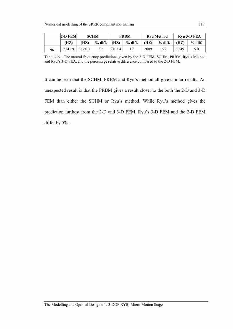
Numerical modelling of the 3RRR compliant mechanism 117
The Modelling and Optimal Design of a 3-DOF XYθZ Micro-Motion Stage
2-D FEM SCHM PRBM Ryu Method Ryu 3-D FEA
(HZ) (HZ) % diff. (HZ) % diff. (HZ) % diff. (HZ) % diff.
ωωωωn 2141.9 2060.7 3.8 2103.4 1.8 2009 6.2 2249 5.0
Table 4-6 – The natural frequency predictions given by the 2-D FEM, SCHM, PRBM, Ryu’s Method
and Ryu’s 3-D FEA, and the percentage relative difference compared to the 2-D FEM.
It can be seen that the SCHM, PRBM and Ryu’s method all give similar results. An
unexpected result is that the PRBM gives a result closer to the both the 2-D and 3-D
FEM than either the SCHM or Ryu’s method. While Ryu’s method gives the
prediction furthest from the 2-D and 3-D FEM. Ryu’s 3-D FEM and the 2-D FEM
differ by 5%.

Numerical modelling of the 3RRR compliant mechanism 118
The Modelling and Optimal Design of a 3-DOF XYθZ Micro-Motion Stage
4.4 3RRR compliant mechanism
The 3RRR mechanism studied in this thesis has been modelled using the 2-D FEM,
SCHM and PRBM. The geometry of the mechanism is taken from the prototype
presented by Zou (2000). To simplify the model, and to give a better comparison
with the experimentally determined Jacobian presented in Chapter 8, the model used
here has had the input flexure hinges removed, as shown in Figure 4-10. The
coordinates defining the hinge locations are given in Table 4-7. To compare the
models the Jacobian, input stiffness, output stiffness and natural frequency of the
models are determined.
Figure 4-10- Schematic of the original 3RRR compliant mechanism (the end-effector is represented as
a triangle).
Hinge (x,y) (mm)
A2 (28, 10)
B2 (23, 27)
C2 (12, 27)
Table 4-7 – Coordinates defining hinge locations.

Numerical modelling of the 3RRR compliant mechanism 119
The Modelling and Optimal Design of a 3-DOF XYθZ Micro-Motion Stage
From Figure 4-10 and 4-12 it can be noted that a new term, ∆Di (i=1,2,3), has been
introduced. This term refers to the displacement change of the compliant mechanism,
at the point where the piezo-actuator force is applied, and in the direction of the force
applied by the piezo-actuator, Fin. The piezo-actuator input forces are applied to the
input-links, which are also defined in Figure 4-10. If the displacement ∆Di is due to
an input from the ith piezo-actuator, and all the piezo-actuator elongation, ∆Li, is
transferred to the ith input-link, then ∆Di equals ∆Li. This is the assumption made in
the models. However, as will be demonstrated in later sections, in the real micro-
motion stage the displacement of the compliant mechanism, ∆Di, may be different to
the elongation of the piezo-actuator, ∆Li. In other cases the displacement, ∆Di, will
be caused by coupling forces rather than the input of a piezo-actuator.
4.4.1 2-D Finite Element Model (FEM)
The 3RRR compliant mechanism, end-effector and the bolts joining them are
modelled using a 2-D analysis with PLANE82 elements. The meshed ANSYS model
is shown in Figure 4-11. The areas representing the bolts, as shown in Figure 4-11,
are areas where the compliant mechanism, end-effector and bolts overlap. These
areas are glued together, so that the compliant mechanism, end-effector and bolt
nodes in these areas are fixed together. The PLANE82 elements are set to have
plane-stress with thickness. The density of the compliant mechanism and end-
effector elements is set to the density of aluminium. The density of the bolt elements
is set such that the mass of the model bolt would equal the real mass of the bolts and
spacers, which was measured. The parameters of the elements used is given in Table

Numerical modelling of the 3RRR compliant mechanism 120
The Modelling and Optimal Design of a 3-DOF XYθZ Micro-Motion Stage
4-8. It can be noted that the density used for the bolts is considerably greater than the
density of the other elements, which indicates the importance of measuring their
mass and accounting for this.
Figure 4-11- ANSYS image of meshed 2-D FEM of the 3RRR compliant mechanism, end-effector
and bolts.
A free mesh was used to create the mesh. To ensure the mesh size was suitable a
number of analysis were made using different mesh sizes. The output was the same
each time confirming that the choice of mesh was suitable. The final mesh used had
15196 nodes. So that the model would be equivalent to the SCHM and PRBM the
nodes at the base of hinge A were constrained to have zero degrees-of-freedom,
rather than only constraining the nodes surrounding the base mounting holes.

Numerical modelling of the 3RRR compliant mechanism 121
The Modelling and Optimal Design of a 3-DOF XYθZ Micro-Motion Stage
Compliant Mechanism End-Effector Mounting Bolts
Element type PLANE82,
plane stress w/ thickness
PLANE82,
plane stress w/
thickness
PLANE82,
plane stress w/
thickness
E (GPa) 72 72 72
G (GPa) 27 27 27
υυυυ 0.33 0.33 0.33
Density
(kg/m3)
2810 2810 13058
Thickness
(mm)
11.7 6 11.7
Table 4-8 - Parameters for elements used in 2-D FEM of 3RRR compliant mechanism.
4.4.2 SCHM
A schematic diagram of the SCHM model is shown in Figure 4-12.
Figure 4-12- Schematic diagram of SCHM of the 3RRR mechanism.
The links of the model uses BEAM3 elements with realistic parameters, so that they
model the deflection of the links as well as the hinge deflections, while the end-
effector is modelled using three PLANE2 elements, as shown in Figure 4-13. The

Numerical modelling of the 3RRR compliant mechanism 122
The Modelling and Optimal Design of a 3-DOF XYθZ Micro-Motion Stage
density of the BEAM3 elements and the PLANE2 elements are set so that the model
elements will have the same mass as the real components, although their volumes are
different due to their different shape. The parameters used for these elements are
given in Table 4-9. The flexure hinges are modelled using the same elements as
described in section 4.1.2.
Figure 4-13 - ANSYS image of meshed SCHM of the 3RRR compliant mechanism and end-effector.
The nodes of PLANE2 elements only have 2-DOF: translations in the x and y plane.
Therefore, this element cannot correctly model the rotational constraints at the
corners where the links join the end-effector. To remedy this problem the corner
nodes of the end-effector are also joined by BEAM3 elements, which have 3-DOF: x,
y translation and rotation about the z-axis. These BEAM3 elements are set to be very
rigid and have no mass.

Numerical modelling of the 3RRR compliant mechanism 123
The Modelling and Optimal Design of a 3-DOF XYθZ Micro-Motion Stage
Compliant Mechanism End-Effector
Link AB Link BC
Element type BEAM3 BEAM3 PLANE2,
plane stress w/ thickness BEAM3
E (GPa) 72 72 72 1000
υυυυ 0.33 0.33 0.33 0.33
Mass (kg) 0.0047 0.0026 0.0669 N/A
Density (kg/m3) 3255 2044 9835 0
Thickness (mm) 11.7 11.7 6 6
Width (mm) 7 10 N/A 10
Table 4-9 - Parameters for compliant mechanism links and end-effector used in the SCHM.
The accuracy of the flexure hinge stiffness prediction has a significant effect on the
model performance. The SCHM model used values for Kx, Ky and Kb calculated
using the analytical equations presented by Paros-Weisbord, Wu and Lobontiu. The
values given by these equations, KAnalytical are shown in Table 4-10. A 2-D FEA of
this hinge geometry was conducted and these values, KFEA, are also shown in Table
4-10. The percentage difference between the analytical equations and the FEA is also
given in Table 4-10. It can be seen that there is a significant difference in the flexure
hinge bending stiffness, Kb, predicted by these two methods, while Kx and Ky are in
close agreement. Kb and Kx were calculated using equations (4.1) and (4.2)
respectively. Ky was calculated using equations (4.7), (4.10) and (4.11). This uses the
shear compliance term given by Lobontiu in equation (4.10). It was found that this
shear compliance term was crucial to the accuracy of Ky. If the shear compliance
term given by Paros-Weisbord or Wu, equations (4.8) and (4.9), respectively is used
then Ky equals 7.69x10⁷. The difference to the FEA of this term is 27.5%. The FEA
stiffness values, KFEA, are also used in the SCHM and the results compared to the
model using the analytical stiffness equations.

Numerical modelling of the 3RRR compliant mechanism 124
The Modelling and Optimal Design of a 3-DOF XYθZ Micro-Motion Stage
ANSYS 2-D FEA, KFEA Analytical Equations, KAnalytical % diff.
Kb(Nm/rad) 36.8 45.3 -23.1
Kx(N/m) 3.83e8 3.85e8 -0.5
Ky(N/m) 6.03e7 6.08e7 -0.8
Table 4-10- Flexure hinge stiffness terms determined from a 2-D FEA and from the analytical
equations, and the percentage relative difference compared to the 2-D FEA.
4.4.3 PRBM
The PRBM and SCHM have the same appearance as they have the same geometry.
Like the SCHM, two values of hinge stiffness Kb have been used; the value given by
the analytical equations and the value given by the FEA analysis. The BEAM3
elements have E equal to 104 GPa, to ensure that the link deflections are insignificant.
4.4.4 Comparison of computational efficiency
The major advantage of the SCHM or PRBM models, compared to the more accurate
2-D FEM, is the shorter computation time of the simpler models, and thus better
computational efficiency. To demonstrate this, the computation time of the models is
compared. Table 4-11 gives the time required to build, mesh and solve each of the
models. The models were all created from commands stored in text files. The
solution was calculated for one static load case. The computation time to derive the
dynamic model of the analytical PRBM is also given. This was derived in Matlab.
The times given are the clock-time rather than the CPU time. The programs were run
on a 1.8GHz Intel Pentium 4 processor.

Numerical modelling of the 3RRR compliant mechanism 125
The Modelling and Optimal Design of a 3-DOF XYθZ Micro-Motion Stage
2-D FEM SCHM PRBM
(Numerical)
PRBM
(Analytical)
Computation Time (s) 16.9 1.8 1.8 1.7
Table 4-11 - Computation time to build, mesh and solve the 2-D FEM, SCHM and PRBM.
From Table 4-11 it can be seen that the SCHM and the two PRBM, have a similar
computation time, which is far shorter than the 2-D FEM computation time. The
SCHM and PRBM computation time is approximately 1/9th that of the 2-D FEM.
Therefore, if the SCHM is able to give accuracy close to the 2-D FEM, it would be a
far more efficient model to be used in parametric study or optimisation, where
hundreds or thousands of iterations may be created.
4.5 Modelling results
4.5.1 Model Jacobians
In Chapter 3 it was demonstrated that the kinematics of the 3RRR compliant
mechanism derived using the PRBM can be represented by a constant Jacobian. Such
a Jacobian is shown in equation (4.12) below. It should be noted that in this equation
the input displacement of the compliant mechanism, ∆Di, is used rather than the
piezo-actuator elongation, ∆Li. The reason for this will become clear when the
experimental results are presented in Chapter 8.
∆
∆
∆
=
∆
∆
∆
3
2
1
333231
232221
131211
D
D
D
JJJ
JJJ
JJJ
Y
X
Zθ (4.12)

Numerical modelling of the 3RRR compliant mechanism 126
The Modelling and Optimal Design of a 3-DOF XYθZ Micro-Motion Stage
Using the ANSYS models the constants that fill this Jacobian are determined using
the following investigative procedure. Each input-link is displaced independently by
∆D, as described in Figure 4-12, while the other two links are constrained to have
zero displacement. The end-effector displacement and rotation are then recorded.
Using the results from the three displacement cases the Jacobian can be filled one
column at a time as shown in equation (4.13) for input-link 1.
++∆
++∆
++∆
=
∆
=
∆∆
∆∆
∆∆
00
00
00
0
0
)(
)(
)(
311
211
1111
333231
232221
131211
1
1
1
JD
JD
JDD
JJJ
JJJ
JJJ
D
DY
DX
Zθ (4.13)
The length of ∆D can be chosen arbitrarily as the Jacobian is linear and its elements
are constants.
The Jacobians derived for the models are shown below. The Jacobians derived by the
2-D FEM, the SCHM and the PRBM are shown in Tables 4-12 and 4-13. In Table 4-
13 the percentage relative difference between the SCHM and PRBM compared to the
2-D FEM is also given.
2-D FEM
-1.13 2.27 -1.14
1.97 -0.01 -1.96
-41.69 -41.80 -41.77
Table 4-12- Jacobian determined using the 2-D FEM.

Numerical modelling of the 3RRR compliant mechanism 127
The Modelling and Optimal Design of a 3-DOF XYθZ Micro-Motion Stage
SCHM PRBM
Kanalytical KFEA Kanalytical KFEA
-1.15 2.31 -1.16 -1.22 2.45 -1.23 -1.61 3.22 -1.61 -1.61 3.22 -1.61
2.01 -0.01 -2.00 2.12 -0.01 -2.11 2.79 0.00 -2.79 2.79 0.00 -2.79
-42.77 -42.52 -42.78 -45.24 -45.02 -45.25 -59.69 -59.66 -59.69 -59.69 -59.66 -59.69
% diff. to 2-D FEM % diff. to 2-D FEM % diff. to 2-D FEM % diff. to 2-D FEM
-2.0 -2.1 -1.9 -8.0 -7.9 -7.5 -43.0 -42.2 -41.1 -43.0 -42.2 -41.1
-2.0 0.0 -2.0 -7.7 0.0 -7.8 -41.8 100.0 -42.4 -41.8 100.0 -42.4
-2.6 -1.7 -2.4 -8.5 -7.7 -8.3 -43.2 -42.7 -42.9 -43.2 -42.7 -42.9
Table 4-13- Jacobians determined using the SCHM and PRBM, and the percentage relative difference
compared to the 2-D FEM.
It can be seen from the results in Table 4-13 that the SCHM using the analytical
stiffness equations gives a Jacobian within 2.6% of 2-D FEM Jacobian. An
unexpected, and unexplained, result is that when the FEA prediction of the flexure
hinge stiffness is used, the resulting Jacobian differs to the 2-D FEM Jacobian by 7-
9%. The SCHM prediction is much closer to the 2-D FEM than the PRBM, which
differs to the 2-D FEM by over 40%. The PRBM Jacobian is not affected by the
value of Kb.
4.5.2 Comparison with the analytically derived Jacobian
The analytically derived Jacobian, which was presented in Chapter 3, and the
numerically derived Jacobian, are both shown in Table 4-14. It can be noted that the
analytically and numerically derived Jacobians are almost identical.

Numerical modelling of the 3RRR compliant mechanism 128
The Modelling and Optimal Design of a 3-DOF XYθZ Micro-Motion Stage
PRBM- Jacobians
Numerically Derived Analytically Derived
-1.61 3.22 -1.61 -1.62 3.24 -1.62
2.79 0.00 -2.79 2.80 0.00 -2.80
-59.69 -59.66 -59.69 -59.96 -59.96 -59.96
Table 4-14 - Comparison of numerically and analytically derived Jacobians using the PRBM for the
3RRR compliant mechanism.
4.5.3 Input stiffness
A force, Fin, of 1N is applied to the input-link of the models, as shown in Figure 4-10
and 4-12, and the displacement, ∆D2, is determined. A check was performed of the 2-
D FEM that showed that the point load did not cause significant local deformation of
the mesh. The load was also applied as a distributed pressure and this gave the same
displacement as a point load. The input stiffness, Kin, is given by Kin = Fin / ∆D2. Due
to the symmetry of the 3RRR mechanism the force need only be applied to one link
as the other links are the same. The results for the 2-D FEM, SCHM and PRBM are
shown in Table 4-15.
2-D FEM SCHM PRBM
Kanalytical KFEA Kanalytical KFEA
% diff. % diff. % diff. % diff.
Kin 1.58e7 2.04e7 -29.1 1.77e7 -12.2 3.08e7 -95.3 2.51e7 -58.8
Table 4-15- Input stiffness predicted by the 2-D FEM, SCHM and PRBM, and the percentage relative
difference compared to the 2-D FEM.
From Table 4-15 it can be seen that the 2-D FEM, SCHM and PRBM give different
predictions for Kin. The SCHM prediction is much closer to the 2-D FEM than the
PRBM. The choice of K values also has a very significant effect on the result. If
KFEA is used then both the SCHM and PRBM give a result far closer to the FEM.

Numerical modelling of the 3RRR compliant mechanism 129
The Modelling and Optimal Design of a 3-DOF XYθZ Micro-Motion Stage
Thus the accuracy of the model is limited by the accuracy of the analytical equations
used to give Kb, Kx and Ky.
4.5.4 Comparison with the analytically derived stiffness
The analytically derived PRBM stiffness matrix was presented in Chapter 3 and is
shown again here.
=
3.07e77.68e57.68e5
7.68e53.07e77.68e5
7.68e57.68e53.07e7
3RRRK (4.14)
According to this model the input stiffness is 3.07x10⁷ N/m. The equivalent ANSYS
PRBM predicted input stiffness was 3.08 x10⁷ N/m. As expected the results are
nearly identical.
4.5.5 Natural frequency
A modal analysis was performed in ANSYS to determine the natural frequencies of
the models. The 2-D FEM used the Block Lanczos mode extraction method, while
the PRBM and SCHM used the reduced mode extraction method. The first three
modes were determined. These modes correspond to two translational modes in the
x-, y- plane and one rotational mode about the z-axis. Figures 4-14 to 4-16 show
sequences of images taken from an animation, generated in ANSYS, of each mode of
the 2-D FEM. Table 4-16 gives the natural frequencies predicted by the 2-D FEM,

Numerical modelling of the 3RRR compliant mechanism 130
The Modelling and Optimal Design of a 3-DOF XYθZ Micro-Motion Stage
SCHM and PRBM. The percentage relative difference between the SCHM and
PRBM compared to the 2-D FEM is also given.
Figure 4-14 - Sequence of images from an animation generated in ANSYS of the first translational
mode, 661Hz, of the 2-D FEM of the 3RRR compliant mechanism.
Figure 4-15 – Sequence of images from an animation generated in ANSYS of the second translational
mode, 661Hz, of the 2-D FEM of the 3RRR compliant mechanism.
Figure 4-16 - Sequence of images from an animation generated in ANSYS of the first rotational mode,
1004Hz, of the 2-D FEM of the 3RRR compliant mechanism.
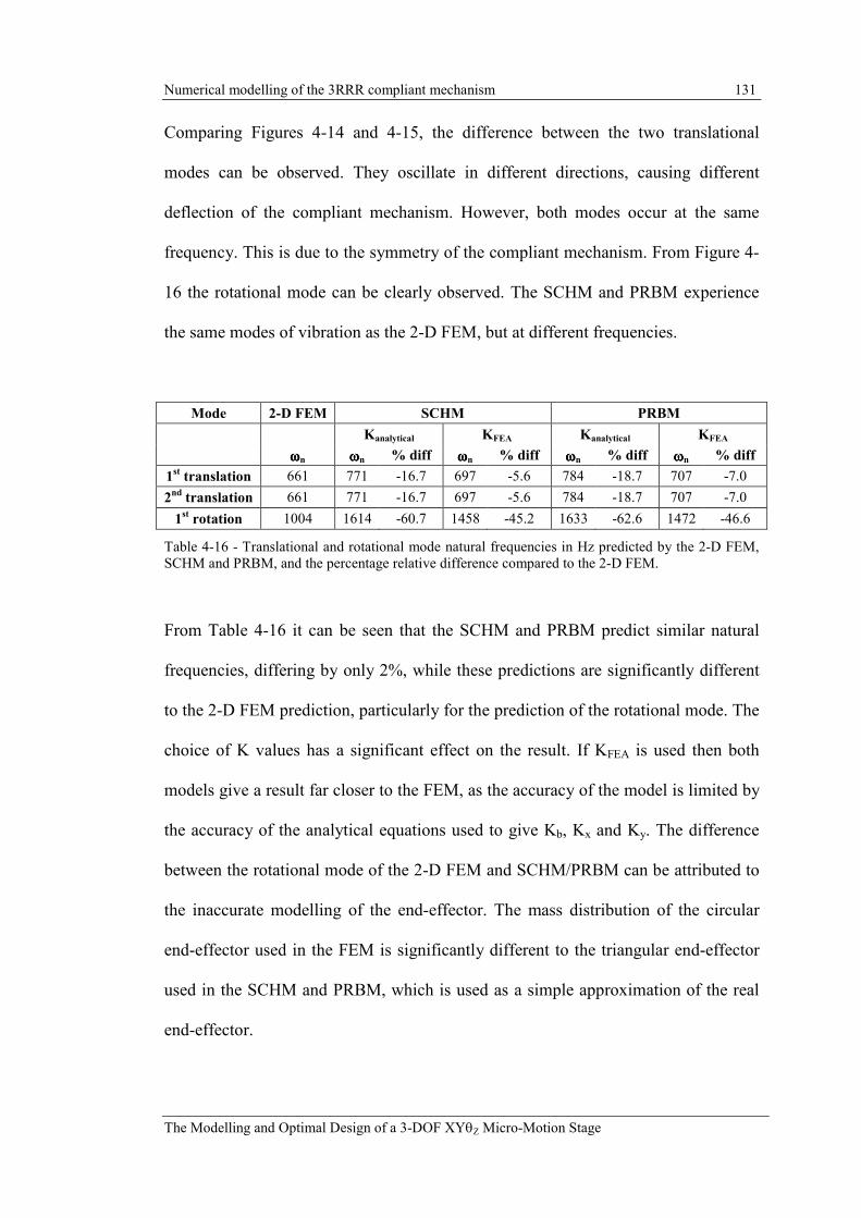
Numerical modelling of the 3RRR compliant mechanism 131
The Modelling and Optimal Design of a 3-DOF XYθZ Micro-Motion Stage
Comparing Figures 4-14 and 4-15, the difference between the two translational
modes can be observed. They oscillate in different directions, causing different
deflection of the compliant mechanism. However, both modes occur at the same
frequency. This is due to the symmetry of the compliant mechanism. From Figure 4-
16 the rotational mode can be clearly observed. The SCHM and PRBM experience
the same modes of vibration as the 2-D FEM, but at different frequencies.
Mode 2-D FEM SCHM PRBM
Kanalytical KFEA Kanalytical KFEA
ωωωωn ωωωωn % diff ωωωωn % diff ωωωωn % diff ωωωωn % diff
1st translation 661 771 -16.7 697 -5.6 784 -18.7 707 -7.0
2nd translation 661 771 -16.7 697 -5.6 784 -18.7 707 -7.0
1st rotation 1004 1614 -60.7 1458 -45.2 1633 -62.6 1472 -46.6
Table 4-16 - Translational and rotational mode natural frequencies in Hz predicted by the 2-D FEM,
SCHM and PRBM, and the percentage relative difference compared to the 2-D FEM.
From Table 4-16 it can be seen that the SCHM and PRBM predict similar natural
frequencies, differing by only 2%, while these predictions are significantly different
to the 2-D FEM prediction, particularly for the prediction of the rotational mode. The
choice of K values has a significant effect on the result. If KFEA is used then both
models give a result far closer to the FEM, as the accuracy of the model is limited by
the accuracy of the analytical equations used to give Kb, Kx and Ky. The difference
between the rotational mode of the 2-D FEM and SCHM/PRBM can be attributed to
the inaccurate modelling of the end-effector. The mass distribution of the circular
end-effector used in the FEM is significantly different to the triangular end-effector
used in the SCHM and PRBM, which is used as a simple approximation of the real
end-effector.

Numerical modelling of the 3RRR compliant mechanism 132
The Modelling and Optimal Design of a 3-DOF XYθZ Micro-Motion Stage
These results suggest that either a SCHM or PRBM could be used to give a
prediction of natural frequency close to the 2-D FEM, provided that the mechanism
and end-effector topology are accurately modelled.
4.5.6 Comparison with the analytically derived natural frequency
The natural frequencies calculated using the analytical PRBM of the 3RRR
compliant mechanism was given in Chapter 3, and is given again in Table 4-17. The
natural frequency prediction given by the numerical PRBM, using Kanalytical, is also
given again in Table 4-17. It can be seen that the two methods predict very similar
results.
Mode Analytical PRBM Numerical PRBM %
ωωωωn ωωωωn diff
1st translation 784 793 1.1
2nd translation 784 793 1.1
1st rotation 1633 1678 2.8
Table 4-17 - Natural frequencies predicted by the numerical and analytical PRBM, and the difference
between them.
4.6 Static-Coupling
Coupling describes the interference between actuators caused by the transmission of
forces through the mechanism from one input-link to another. This can cause
complication of the control system as the actuators are not independent. To
determine the degree of coupling a force, Fin, is applied to input-link 2, causing
displacement of all links of the mechanism, as shown in Figure 4-17. The
displacement of the input-links at the point of piezo-actuator contact is given by ∆Di

Numerical modelling of the 3RRR compliant mechanism 133
The Modelling and Optimal Design of a 3-DOF XYθZ Micro-Motion Stage
(i=1,2,3). The couplings between input-link 1 and 2, and input-link 3 and 2, are given
respectively by equations (4.15) and (4.16).
Coupling 1/2 = ∆D1 / ∆D2 (4.15)
Coupling 3/2 = ∆D3 / ∆D2 (4.16)
Figure 4-17 - Schematic showing coupling between input links.
In this study coupling will only be determined for a static load case and therefore the
resulting coupling is termed static-coupling. The static-coupling for the 3RRR
compliant mechanism is given in Table 4-18.

Numerical modelling of the 3RRR compliant mechanism 134
The Modelling and Optimal Design of a 3-DOF XYθZ Micro-Motion Stage
2-D FEM SCHM PRBM
Kanalytical KFEA Kanalytical KFEA
%
diff.
%
diff.
%
diff.
%
diff.
Static-Coupling
1/2 -0.010 -0.010 -4.0 -0.012 -22.5 -0.024 -144.7 -0.024 -144.8
Static-Coupling
3/2 -0.010 -0.010 -4.0 -0.012 -22.5 -0.024 -144.7 -0.024 -144.8
Table 4-18 - Static-coupling for the 3RRR compliant mechanism predicted by the 2-D FEM, SCHM
and PRBM.
From Table 4-18 it can be observed that static-coupling 1/2 and 3/2 are identical.
This is due to the symmetry of the compliant mechanism. It can also be observed that
the 2-D FEM and SCHM using Kanalytical predict similar static-coupling. However, the
result predicted by the SCHM when using KFEA is significantly different to the 2-D
FEM, which is unexpected. The PRBM predicts static-coupling that is significantly
different to the 2-D FEM, and is almost unaffected by the use of Kanalytical or KFEA.
4.6.1 Comparison with the analytically derived static-coupling
From inspection of the analytically derived stiffness matrix given in equation (4.14),
it can be seen that there are non-diagonal terms in the matrix. These are the coupling
terms. To determine the static-coupling the inverse of the stiffness matrix is
determined, as given in equation (4.17).
=
8-3.26e10-8e-10-8e-
10-8e-8-3.26e10-8e-
10-8e-10-8e-8-3.26e
)( 3RRRKinv (4.17)

Numerical modelling of the 3RRR compliant mechanism 135
The Modelling and Optimal Design of a 3-DOF XYθZ Micro-Motion Stage
The non-diagonal terms are then divided by the diagonal terms to give the static-
coupling terms, as given in equation (4.18). Due to the symmetry of the 3RRR
compliant mechanism all the static-coupling terms are the same.
( )( )diagonal
diagonalnon
Kinv
KinvCouplingStatic
−=− (4.18)
The static-coupling predicted by the analytical and numerical PRBM are given in
Table 4-19. The difference between them is also given. It can be seen that both
models give very similar predictions.
Analytical PRBM Numerical PRBM %
ωωωωn ωωωωn diff
Static-Coupling 1/2 -0.024 -0.024 -0.25
Static-Coupling 3/2 -0.024 -0.024 -0.25
Table 4-19 - Static-coupling predicted by the analytical and numerical PRBM, and the difference
between them.
4.7 Discussion
These results demonstrate that the SCHM can represent the kinematics and dynamics
of a flexure hinge mechanism with accuracy close to a 2-D FEM. However, the
SCHM accuracy is limited by the analytical equations giving the Kb, Kx and Ky
terms, whose accuracy varies depending on the dimensions of the flexure hinge. The
SCHM provides much improved results compared to a PRBM, particularly for the
geometry of 3RRR compliant mechanism considered in this chapter. The SCHM
kinematic model of the 3RRR compliant mechanism is within 1% of the 2-D FEM,

Numerical modelling of the 3RRR compliant mechanism 136
The Modelling and Optimal Design of a 3-DOF XYθZ Micro-Motion Stage
compared to over 40% difference between the PRBM and the 2-D FEM. However, a
surprising result is that the SCHM using KFEA stiffness terms gives a prediction 8%
different to the 2-D FEM. The reason for this is unclear. The predictions for stiffness
and natural frequency are much improved when the KFEA terms are used. The PRBM
gives very similar predictions for natural frequency as the SCHM.
The SCHM is easy to generate and very quick to solve. It takes approximately 1/9th
of the computation time of the equivalent 2-D FEM. Because if its accuracy and
short computation time, the SCHM is well suited to be used in a parametric study
and optimisation, which will be presented in Chapters 6 and 7, respectively.
The analytically and numerically derived PRBM have been demonstrated to be the
same. The minor discrepancies between them can be attributed to small differences
within the computations used to derive them.
Experimental validation of the models is discussed in Chapter 8.