chapter 10: pedestrian facility design - nacto.org · chapter 10: pedestrian facility design ......
TRANSCRIPT

Chapter 10:
Pedestrian Facility Design
ACCESS MINNEAPOLIS Design Guidelines for Streets & Sidewalks
October 26, 2009


Design Guidelines for Streets and Sidewalks
Ch 10 Pedestrian Facility Design October 26, 2009
TABLE OF CONTENTS
10 PEDESTRIAN FACILITY DESIGN ....................................................................... 10-1
10.0 INTRODUCTION ......................................................................................................... 10‐1 10.0.1 Principles for Pedestrian Facility Design........................................................................................ 10‐1 10.0.2 Background/Purpose..................................................................................................................... 10‐1 10.0.3 Relationship to Accessibility Standards......................................................................................... 10‐2 10.0.4 Relationship to Roadway Design Guidelines ................................................................................. 10‐2
10.1 PEDESTRIAN NETWORK ............................................................................................... 10‐3 10.1.1 New Sidewalk Construction........................................................................................................... 10‐3
10.1.1.1 New Street Construction............................................................................................................................10‐3 10.1.1.2 Reconstruction and Renovation of Existing Streets ...................................................................................10‐3 10.1.1.3 Infill Development......................................................................................................................................10‐4 10.1.1.4 Exceptions..................................................................................................................................................10‐4
10.1.2 Street and Walkway Grid............................................................................................................... 10‐4 10.1.2.1 Street Vacations.........................................................................................................................................10‐4 10.1.2.2 New Streets................................................................................................................................................10‐4 10.1.2.3 Walkways and Trails...................................................................................................................................10‐4
10.2 PEDESTRIAN ZONE DESIGN........................................................................................... 10‐5 10.2.1 Pedestrian Zone Organization ....................................................................................................... 10‐5
10.2.1.1 Frontage Zone............................................................................................................................................10‐6 10.2.1.2 Through Walk Zone....................................................................................................................................10‐6 10.2.1.3 Planting/Furnishing Zone ........................................................................................................................... 10‐7 10.2.1.4 Curb Zone...................................................................................................................................................10‐7
10.2.2 Specialty Zones.............................................................................................................................. 10‐7 10.2.2.1 Clear Corner Zone ......................................................................................................................................10‐8 10.2.2.2 Corner Public Use Zone..............................................................................................................................10‐8 10.2.2.3 Bus Stop Zone ............................................................................................................................................10‐8
10.2.3 Pedestrian Zone Width by Street Design Type.............................................................................. 10‐8 10.2.4 Solutions for Existing Constrained Conditions .............................................................................. 10‐9 10.2.5 Placement of Elements in the Pedestrian Zone .......................................................................... 10‐12 10.2.6 Encroachments and Active Uses of the Pedestrian Zone............................................................ 10‐13
10.2.6.1 Stairs/Ramps/Doors .................................................................................................................................10‐13 10.2.6.2 Commercial Signs.....................................................................................................................................10‐13 10.2.6.3 Sidewalk Cafes .........................................................................................................................................10‐13 10.2.6.4 Street Vendors .........................................................................................................................................10‐14
10.2.7 Sidewalk Surface Design.............................................................................................................. 10‐14 10.2.7.1 Material and Surface Finish......................................................................................................................10‐14 10.2.7.2 Sidewalk Grade and Cross‐Slope..............................................................................................................10‐17 10.2.7.3 Grates.......................................................................................................................................................10‐17
10.2.8 Driveway, Alley, & Railroad Crossings of Sidewalks .................................................................... 10‐17 10.2.8.1 Driveways and Alleys ...............................................................................................................................10‐17 10.2.8.2 At‐Grade Railroad Crossings ....................................................................................................................10‐19
10.2.9 Sidewalks on Bridges ................................................................................................................... 10‐20 10.2.9.1 Pedestrian Zone Organization and Widths ..............................................................................................10‐20 10.2.9.2 Lighting.....................................................................................................................................................10‐21 10.2.9.3 Barriers from Traffic.................................................................................................................................10‐21 10.2.9.4 Railings .....................................................................................................................................................10‐21 10.2.9.5 Visibility....................................................................................................................................................10‐22 10.2.9.6 Retrofitting pedestrian improvements on bridges...................................................................................10‐22
10.2.10 Sidewalks under Bridges.............................................................................................................. 10‐23 10.2.10.1 Pedestrian Zone Organization and Widths ..............................................................................................10‐23 10.2.10.2 Pier Design and Placement ...................................................................................................................... 10‐23

Design Guidelines for Streets and Sidewalks
Ch 10 Pedestrian Facility Design October 26, 2009
10.2.10.3 Retaining Wall Design ..............................................................................................................................10‐23 10.2.10.4 Lighting.....................................................................................................................................................10‐23 10.2.10.5 Snow and Ice Clearance ...........................................................................................................................10‐23
10.3 STREET CORNERS..................................................................................................... 10‐23 10.3.1 Elements of Good Corner Design ................................................................................................ 10‐24
10.3.1.1 Corner Space............................................................................................................................................10‐24 10.3.1.2 Visibility at Corners ..................................................................................................................................10‐24
10.3.2 Curb Return or Corner Radii ........................................................................................................ 10‐25 10.3.3 Curb Ramps ................................................................................................................................. 10‐25
10.3.3.1 Number of Ramps ....................................................................................................................................10‐25 10.3.3.2 Types of Curb Ramps ...............................................................................................................................10‐25 10.3.3.3 Technical Details ......................................................................................................................................10‐26 10.3.3.4 Drainage...................................................................................................................................................10‐27 10.3.3.5 Obstructions.............................................................................................................................................10‐27 10.3.3.6 Solutions for Constrained Conditions ......................................................................................................10‐27
10.3.4 Locating Pedestrian Signal Call Buttons ...................................................................................... 10‐29 10.3.5 Curb Extensions ........................................................................................................................... 10‐30
10.3.5.1 Purpose ....................................................................................................................................................10‐30 10.3.5.2 Locations ..................................................................................................................................................10‐30 10.3.5.3 Design ......................................................................................................................................................10‐31
10.3.6 Corner Geometry Retrofit Guidance ........................................................................................... 10‐32
10.4 BUS STOPS............................................................................................................. 10‐33 10.4.1 Bus Stop Sign ............................................................................................................................... 10‐33 10.4.2 Bus Stop Clear Zones ................................................................................................................... 10‐33
10.4.2.1 Accessible Front Door Zone .....................................................................................................................10‐33 10.4.2.2 Through Walk Zone..................................................................................................................................10‐33 10.4.2.3 Back Door Zone ........................................................................................................................................10‐35
10.4.3 Shelter / Bench Zone ................................................................................................................... 10‐35 10.4.3.1 Bus Shelters..............................................................................................................................................10‐35 10.4.3.2 Benches....................................................................................................................................................10‐37
10.4.4 Other Street Furniture and Utilities ............................................................................................ 10‐37 10.4.4.1 Trash Receptacles ....................................................................................................................................10‐37 10.4.4.2 Street Lights and Utilities .........................................................................................................................10‐37 10.4.4.3 Other Street Furniture .............................................................................................................................10‐37
10.4.5 Solutions for Existing Constrained Conditions ............................................................................ 10‐39
10.5 STREET CROSSINGS .................................................................................................. 10‐40 10.5.1 Legal Crosswalk Definition........................................................................................................... 10‐40 10.5.2 Elements of Safe, Accessible and Convenient Crossings ............................................................. 10‐40
10.5.2.1 Frequency of Crossing Opportunities.......................................................................................................10‐40 10.5.2.2 Pedestrian Delay ......................................................................................................................................10‐41 10.5.2.3 Crossing Distance .....................................................................................................................................10‐41 10.5.2.4 Visibility....................................................................................................................................................10‐41 10.5.2.5 Managing Vehicle Speeds ........................................................................................................................10‐41
10.5.3 Crosswalk Markings..................................................................................................................... 10‐42 10.5.3.1 Purpose ....................................................................................................................................................10‐42 10.5.3.2 Location ...................................................................................................................................................10‐42 10.5.3.3 Design ......................................................................................................................................................10‐43 10.5.3.4 Crosswalk Materials .................................................................................................................................10‐44 10.5.3.5 Textured and Colored Pavement Crosswalks...........................................................................................10‐45 10.5.3.6 Advance Stop Bar Markings and Locations ..............................................................................................10‐45
10.5.4 Signs............................................................................................................................................. 10‐45 10.5.4.1 Standard Signs..........................................................................................................................................10‐46 10.5.4.2 Supplemental Signs..................................................................................................................................10‐46

Design Guidelines for Streets and Sidewalks
Ch 10 Pedestrian Facility Design October 26, 2009
10.5.5 Signals.......................................................................................................................................... 10‐47 10.5.5.1 Cycle Lengths / Pedestrian Delay .............................................................................................................10‐47 10.5.5.2 Crossing Interval / Crossing Time.............................................................................................................10‐47 10.5.5.3 Countdown Timers...................................................................................................................................10‐47 10.5.5.4 Pedestrian Detection / Push Buttons.......................................................................................................10‐48 10.5.5.5 Accessible Pedestrian Signals...................................................................................................................10‐49 10.5.5.6 Flashing Warning Beacons and Half Signals .............................................................................................10‐49 10.5.5.7 Leading Pedestrian Intervals ....................................................................................................................10‐50
10.5.6 Pedestrian Refuge and Median Islands ....................................................................................... 10‐50 10.5.6.1 Center Median Islands .............................................................................................................................10‐50 10.5.6.2 Channelized Right Turn Lanes ..................................................................................................................10‐51
10.5.7 Lighting ........................................................................................................................................ 10‐52 10.5.8 Unique Types of Crossings........................................................................................................... 10‐52
10.5.8.1 Mid‐Block .................................................................................................................................................10‐52 10.5.8.2 Freeway Ramps........................................................................................................................................10‐53 10.5.8.3 Cul‐de‐Sacs/Diverters/Closed Streets ......................................................................................................10‐53 10.5.8.4 Raised Intersections and Raised Crossings...............................................................................................10‐53 10.5.8.5 Roundabouts............................................................................................................................................10‐54 10.5.8.6 Grade‐Separated Crossings...................................................................................................................... 10‐54 10.5.8.7 Prohibited Crossings ................................................................................................................................10‐54
10.6 OTHER PEDESTRIAN NETWORKS.................................................................................. 10‐54 10.6.1 Skyway System ............................................................................................................................ 10‐54
10.6.1.1 Appropriate Locations..............................................................................................................................10‐54 10.6.1.2 Design and Placement..............................................................................................................................10‐55 10.6.1.3 Hours of Operation ..................................................................................................................................10‐55 10.6.1.4 Wayfinding...............................................................................................................................................10‐56
10.6.2 Non‐Motorized Trails, Bridges, Underpasses and Stairs ............................................................. 10‐56 10.6.2.1 Non‐Motorized Trails ...............................................................................................................................10‐56 10.6.2.2 Non‐Motorized Bridges............................................................................................................................10‐56 10.6.2.3 Non‐Motorized Underpasses ...................................................................................................................10‐56 10.6.2.4 Stairs ........................................................................................................................................................10‐57
10.7 WAYFINDING.......................................................................................................... 10‐57 10.7.1 Placement and Orientation ......................................................................................................... 10‐57 10.7.2 Wayfinding Design....................................................................................................................... 10‐58 10.7.3 Wayfinding Infrastructure Maintenance..................................................................................... 10‐58
10.8 SITE PLANNING ....................................................................................................... 10‐58 10.8.1 Building Facade ........................................................................................................................... 10‐58 10.8.2 Human‐scale Building Massing, Height and Step‐backs.............................................................. 10‐58 10.8.3 Building Setback .......................................................................................................................... 10‐58 10.8.4 Building Entrance Location.......................................................................................................... 10‐59 10.8.5 Walkways..................................................................................................................................... 10‐59 10.8.6 Parking Lots ................................................................................................................................. 10‐59 10.8.7 Stormwater Runoff...................................................................................................................... 10‐59
10.9 CLOSURES, SAFETY, AND ACCESSIBILITY IN WORK ZONES .................................................. 10‐59
10.10 REFERENCE PUBLICATIONS ......................................................................................... 10‐60

Design Guidelines for Streets and Sidewalks
Ch 10 Pedestrian Facility Design October 26, 2009
FIGURES
Figure 10‐1: Pedestrian Zone ......................................................................................................................................................10‐5 Figure 10‐2: Through Walk Zone Vertical Clearance Requirements ...........................................................................................10‐6 Figure 10‐3: Specialty Zones .......................................................................................................................................................10‐7 Figure 10‐4: Minimum Accessible Passing Zone Intervals...........................................................................................................10‐9 Figure 10‐5: Example of Curb Extension at Vertical Obstruction ..............................................................................................10‐10 Figure 10‐6: Example of a Bypass at Vertical Obstruction ........................................................................................................10‐10 Figure 10‐7: Pedestrian Zone Dimensions by Street Design Type.............................................................................................10‐11 Figure 10‐8: Recommended Placement of Utilities and Street Furnishings in the Pedestrian Zone.........................................10‐12 Figure 10‐9: Maximum Surface Discontinuities ........................................................................................................................10‐16 Figure 10‐10: Decorative Sidewalk Scoring and Pavers in the Planting/Furnishing Zone .........................................................10‐16 Figure 10‐11: Stamped Sidewalk Design....................................................................................................................................10‐16 Figure 10‐12: Sidewalk Cross‐Slope ..........................................................................................................................................10‐17 Figure 10‐13: Sidewalk Driveway and Alley Crossings ..............................................................................................................10‐18 Figure 10‐14: Benefits of Access Management for Pedestrians................................................................................................10‐18 Figure 10‐15: Parking Ramp Access/Egress...............................................................................................................................10‐19 Figure 10‐16: Wheelchair Wheel Stuck in Flangeway ...............................................................................................................10‐19 Figure 10‐17: Planting/Furnishing Zone across Railroad Crossing .............................................................................................10‐20 Figure 10‐18: Minimum Pedestrian Zone Width on Bridges.....................................................................................................10‐21 Figure 10‐19: Example of Pedestrian Barrier and Pedestrian Scale Lighting on Bridge ............................................................10‐22 Figure 10‐20: Conceptual Bridge Design...................................................................................................................................10‐22 Figure 10‐21: Relationship between Corner Space, Corner Radius, and Pedestrian Zone Width.............................................10‐24 Figure 10‐22: Curb Ramp Components.....................................................................................................................................10‐26 Figure 10‐23: Curb Ramp with Returned Edges ........................................................................................................................10‐27 Figure 10‐24: Curb Ramp Solutions for Constrained Conditions...............................................................................................10‐27 Figure 10‐25: Curb Ramp Types ................................................................................................................................................10‐28 Figure 10‐26: Pedestrian Signal Call Button Placement ............................................................................................................10‐29 Figure 10‐27: Safety Benefits of Curb Extensions ..................................................................................................................... 10‐30 Figure 10‐28: Midblock Curb Extension ....................................................................................................................................10‐31 Figure 10‐29: Corner Radius and Curb Extension Retrofit Examples ........................................................................................10‐32 Figure 10‐30: Bus Stop Clear Zones...........................................................................................................................................10‐34 Figure 10‐31: Bus Shelter Placement Options...........................................................................................................................10‐36 Figure 10‐32: Bus Bench Placement Options ............................................................................................................................10‐38 Figure 10‐33: Pedestrians’ Chance of Death if Hit by Motor Vehicle........................................................................................10‐42 Figure 10‐34: Visibility of Lateral vs. Longitudinal Crosswalk Markings....................................................................................10‐44 Figure 10‐35: Staggered Spacing of Longitudinal Crosswalk Markings ......................................................................................10‐44 Figure 10‐36: Advanced Stop Bar..............................................................................................................................................10‐45 Figure 10‐37: MMUTCD Pedestrian crossing sign .....................................................................................................................10‐46 Figure 10‐38: Removable In‐Street Pedestrian Crossing Sign ...................................................................................................10‐47 Figure 10‐39: Pedestrian Countdown Timer .............................................................................................................................10‐48 Figure 10‐40: Pedestrian Signal Call Button..............................................................................................................................10‐49 Figure 10‐41: Angled Median Refuge Island .............................................................................................................................10‐51 Figure 10‐42: Median Refuge Island with Pedestrian Access....................................................................................................10‐51 Figure 10‐43: Proper Design of Channelized Right Turn Lane...................................................................................................10‐52 Figure 10‐44: Raised Intersection .............................................................................................................................................10‐53 Figure 10‐45: Future Skyway Expansion ...................................................................................................................................10‐55 Figure 10‐46: Highly Visible Vertical Skyway Access .................................................................................................................10‐55 Figure 10‐47: Underpass with Good Sight Lines .......................................................................................................................10‐57 Figure 10‐48: Examples of Well‐Designed Pedestrian Facilities in Work Zones........................................................................10‐60
Design Guidelines for Streets and Sidewalks
Ch 10 Pedestrian Facility Design October 26, 2009 Page 10‐1
10 Pedestrian Facility Design
10.0 INTRODUCTION 10.0.1 Principles for Pedestrian Facility Design The following principles are the basis for the guidance in this document and should guide any improvements or modifications to pedestrian facilities.
• The pedestrian system should be safe. Streets, sidewalks, and walkways should be designed to minimize conflicts with motorized and non‐motorized vehicle traffic, minimize tripping hazards and protruding objects, and promote a reality and perception of personal safety.
• The pedestrian system should be accessible to all. The pedestrian system should be designed for all pedestrians, including people with disabilities, seniors, and youth.
• The pedestrian system should provide direct and convenient connections. The pedestrian system should provide continuous and well‐connected sidewalks and walkways and be designed in a manner that is responsive to pedestrians’ desire to reach their destinations using the shortest and quickest route. This should be achieved by providing minimal delays and direct connections while ensuring safety for all users.
• The pedestrian system should provide comfortable places to walk. The pedestrian system should be designed and maintained to promote walking and include elements that create a comfortable walking environment, such as trees, pedestrian‐scaled street lighting, buffers from traffic, trash receptacles, places to sit, and a pedestrian‐scaled environment.
• The pedestrian system should enhance the public realm of the City. The pedestrian system should be designed not only to serve a transportation function, but also to provide public spaces that enhance community interaction, economic vitality, and the image of the City.
• Pedestrian improvements should be cost‐effective and financially sustainable. Pedestrian improvements should be designed and funded to maximize the benefits of the improvements relative to the cost to build and to maintain the improvements.
10.0.2 Background/Purpose The intent of the Pedestrian Facility Design Guide (Guide) is to establish guidelines by which the City of Minneapolis will design infrastructure improvements and carry out policies as they relate to pedestrian facilities within City rights‐of‐way. The Guide was developed as part of the Minneapolis Pedestrian Master Plan and is intended to be Chapter 10 of the City’s Design Guidelines for Streets and Sidewalks developed originally as part of the Access Minneapolis Ten Year Transportation Action Plan (http://www.ci.minneapolis.mn.us/public‐works/trans‐plan/DesignGuidelines.asp).
The Guide is intended to supersede or supplement the following sections of the Design Guidelines for Streets and Sidewalks dated 2/22/08 as indicated below:
• Supersede section 5.1.3 (Pedestrian Zone)
• Supersede section 5.4 (Pedestrian Zone)
• Supersede section 5.8.5 (Crosswalks)
• Supplement section 5.5 (Curb Extensions)

Design Guidelines for Streets and Sidewalks
Ch 10 Pedestrian Facility Design October 26, 2009 Page 10‐2
• Supplement section 5.7 (Utilities)
• Supplement section 5.8.1 (Curb Return or Corner Radii)
• Supplement section 5.9.3 (Design of Transit Shelter/Bus Stop Area and Landing Pads)
The Guide is structured to begin at a broad level, first discussing the overall pedestrian system, then becoming more specific as it addresses sidewalk, street corner, and street crossing designs. The last part of the Guide presents elements of the pedestrian system that are not specific to street right‐of‐way design, such as off‐street paths, wayfinding, and site planning.
10.0.3 Relationship to Accessibility Standards The Americans with Disabilities Act (ADA) of 1990 is a civil rights statute that prohibits discrimination against people with disabilities, and Title II of the ADA applies to the design and construction of pedestrian facilities in the public right‐of‐way. The current ADA design standard is contained in the ADA Accessibility Guidelines (ADAAG), which were principally developed for buildings and site work that are not directly applicable to sidewalks, street crossings, and related pedestrian facilities in the public right‐of‐way. The US Access Board has since developed draft Proposed Rights‐of‐Way Accessibility Guidelines (PROWAG)1 that provide more specific guidance for the design of pedestrian facilities in the public right‐of‐way. The PROWAG guidelines are expected to become the new ADA standard and supersede ADAAG once they are adopted by the US Department of Justice and Department of Transportation. In the interim, the Federal Highway Administration has identified the PROWAG guidelines as the current best practice.2
This Guide includes much of the guidance from the draft PROWAG guidelines. The pedestrian access route, as defined in PROWAG guidelines, is defined as the Through Walk Zone in the Pedestrian Design Guide. The Guide is not intended to replace design standards, and design standards will need to be updated to reflect the PROWAG guidance once the PROWAG becomes the new ADA standard.
10.0.4 Relationship to Roadway Design Guidelines The design of facilities for motor vehicles has a direct impact on the design of pedestrian facilities in a given street corridor. Pedestrian safety, accessibility, mobility, and comfort are enhanced by:
• Slower traffic speeds
• Fewer traffic lanes
• Narrower traffic lanes
• Shorter street crossings
• Clear visibility between pedestrians and vehicles at intersections
• A buffer from traffic provided by wider sidewalks, curbside bike lanes and on‐street parking
• Tighter corner radii
• Space in the sidewalk corridor for trees, planted boulevards, transit shelters, and other street furniture
1 November 23, 2005 draft PROWAG: http://www.access‐board.gov/prowac/draft.htm 2 January 2006FHWA Memorandum: http://www.fhwa.dot.gov/environment/bikeped/prwaa.htm

Design Guidelines for Streets and Sidewalks
Ch 10 Pedestrian Facility Design October 26, 2009 Page 10‐3
However, pedestrian needs are often compromised by competing demands for right‐of‐way space for vehicle movement, transit stops, loading zones, and on‐street parking and other curbside uses. The following sections of the Design Guidelines for Streets and Sidewalks provide guidance regarding roadway designs while also considering pedestrian needs:
• Section 2: Framework for Urban Street Design ‐ includes a street design typology and associated maximum number of desired through lanes for different street types. Following these guidelines will help achieve a better balance among the various transportation modes.
• Section 3: The Design Process ‐ includes guidance on determining modal needs and priorities, forecasting traffic volumes and options for intersection treatments and traffic management.
• Section 4: Design Controls ‐ addresses the appropriate design speed and design vehicle for different street types, which has a direct impact on speed, roadway width, and corner design, which in turn impacts pedestrian safety and comfort.
• Section 5.3: Design Guidance for Lane Widths ‐ addresses appropriate lane widths for different street types, traffic volumes, and modal priorities, all of which must be balanced with pedestrian needs.
• Section 5.8: Design Guidance for Intersections – addresses curb return radii, right turn lanes and bike lanes at intersections. Intersections are high risk areas for pedestrians and shall be designed with pedestrian needs in mind.
In addition, the design of streets for bicyclists has benefits for pedestrians. On‐street bicycle lanes encourage bicyclists to ride in the streets, thereby reducing potential bicycle‐pedestrian conflicts on sidewalks. Curbside bicycle lanes also help to buffer pedestrians from motor vehicle traffic. Chapter 11 of the Design Guidelines for Streets and Sidewalks addresses bikeway design.
10.1 PEDESTRIAN NETWORK Sidewalks are fundamental pedestrian facilities. Sidewalks enable pedestrians to access properties, parks, transit, businesses and employment. They also provide safety from traffic. A high level of connectivity is necessary for an efficient pedestrian network. While Minneapolis has an extensive pedestrian network with sidewalks on over 90% of streets, gaps remain in some locations.
10.1.1 New Sidewalk Construction Gaps within the current network should be completed as part of public and private construction improvements. Sidewalks are particularly important along non‐local streets where higher traffic volumes are likely, where there are existing “cow‐paths,” and where there are gaps in otherwise contiguous sidewalks.
10.1.1.1 New Street Construction
All new street construction should include sidewalks on both sides, including private streets.
10.1.1.2 Reconstruction and Renovation of Existing Streets
Reconstruction and renovation of existing streets should include construction of sidewalks on both sides where sidewalks do not exist.

Design Guidelines for Streets and Sidewalks
Ch 10 Pedestrian Facility Design October 26, 2009 Page 10‐4
10.1.1.3 Infill Development
Infill development should include construction of a continuous sidewalk system adjacent to the development and connecting to the existing sidewalk system. This may require sidewalk construction beyond the property frontage or on an adjacent block.
10.1.1.4 Exceptions
Generally, sidewalks are needed on both sides of all streets. Streets that may require sidewalks on only one side of the street include:
• A street adjacent to a freeway with non‐transportation land uses on only one side.
• A street with severe topographic constraints or mature landscaping. These are locations where the provision of a sidewalk would result in building large retaining walls or removing mature trees.
In all cases, streets with sidewalks on one side of the street shall have safe street crossings to allow pedestrians to access the sidewalks on the continuous side of the street. Cul‐de‐sacs and diverted streets should maintain sidewalk connections.
10.1.2 Street and Walkway Grid The Minneapolis historic street grid provides a high level of connectivity for walking trips. However, there are some gaps in the street grid system, such as those created by historic railroad development, freeway construction, big box retail, and megastructures. These gaps increase walking distances and reduce the convenience of walking.
10.1.2.1 Street Vacations
The connectivity of current and future pedestrian networks should be maintained or improved in every street and right‐of‐way vacation request. Otherwise, street vacations may result in large block sizes and increased travel distances, which are particularly problematic for walking.
10.1.2.2 New Streets
Sidewalks are to be provided along all new streets to improve connectivity and facilitate pedestrian‐oriented development. New streets are particularly effective when designed to typical Minneapolis block dimensions, or smaller.
10.1.2.3 Walkways and Trails
Where blocks are longer than typical blocks in the surrounding area, creation of off‐street pedestrian walkways or multi‐use bicycle and pedestrian trails through the block, providing logical connections to other sidewalks and destinations, is encouraged and should be provided where feasible.

Design Guidelines for Streets and Sidewalks
Ch 10 Pedestrian Facility Design October 26, 2009 Page 10‐5
10.2 PEDESTRIAN ZONE DESIGN The pedestrian zone – the space between the curb and the property line – plays an important role in providing: safe and efficient movement of pedestrians of all abilities and disabilities; access to properties, on‐street parking, and transit; necessary space for above ground street utilities, traffic control, trees and street furniture; and space for sidewalk cafés, street vendors and other active uses.
10.2.1 Pedestrian Zone Organization The pedestrian zone should be organized into four distinct subzones that maintain an accessible walking path and organize the placement of elements. The four subzones are the Curb Zone, the Planting/Furnishing Zone, the Through Walk Zone, and the Frontage Zone (see Figure 10‐1).
The following guidelines are intended for use in street reconstruction or large‐scale redevelopment projects when it is feasible to alter curb lines; considerations for constrained conditions on existing narrow sidewalk corridors are addressed in section 10.2.4. Considerations for bridges are addressed in section 10.2.9, and considerations for transit stops are addressed in section 10.4.
Figure 10‐1: Pedestrian Zone
Commercial Context Residential Context

Design Guidelines for Streets and Sidewalks
Ch 10 Pedestrian Facility Design October 26, 2009 Page 10‐6
10.2.1.1 Frontage Zone
Use: The Frontage Zone is the space at the edge of the walkway adjacent to the property line. It reflects the varying level of activity associated with property frontage and is wider where people are likely to window shop or activities such as sidewalk cafes are allowed. It also reflects the tendency of people to shy away from walls above waist height. The Frontage Zone may also be used as a secondary area for plantings, street furniture and social activities.
Width: 1.5 feet recommended minimum, 1.0 foot acceptable minimum (see Figure 10‐7).
Special Considerations: People tend to shy away from a building, wall, fence, steps or railing by at least 1 foot. In constrained conditions away from major pedestrian generators or where there are wide building setbacks, this distance may be decreased. In activity centers and neighborhood commercial nodes, this width should be increased to allow for café tables, seating, benches, planting, and other amenities, as well as higher volumes of retail‐related pedestrian activity.
10.2.1.2 Through Walk Zone
Use: The Through Walk Zone contains the basic sidewalk width or clear area for pedestrian travel and is sized to provide for two directions of pedestrian travel. The Through Walk Zone should have a safe and accessible walking surface and be free of vertical obstructions and protruding objects.
Width: 6.0 feet recommended minimum, 5.0 feet acceptable minimum (see Figure 10‐7).
Special considerations:
• 5 feet is the necessary width for two wheelchairs to pass each other.
• 6 feet is the necessary width for two wheelchairs or two people pushing strollers to walk side by side comfortably.
• If 5 feet is used, the Frontage Zone should be clear of steps, fencing, and railings that may impede pedestrian movement.
• For downtown and activity centers, the preferred width may need to be greater than 6 feet.
• Wall‐ or post‐mounted objects placed between 27 and 80 inches above the walking surface may not extend more than 4 inches horizontally to prevent hazards for people with vision impairments (see Figure 10‐2).
• Through Walk Zone surfaces should be designed as explained in section 10.2.7 Sidewalk Surface Design.
Figure 10‐2: Through Walk Zone Vertical Clearance Requirements
Source: Designing Sidewalks and Trails for Access, Part II, FHWA, 2001.

Design Guidelines for Streets and Sidewalks
Ch 10 Pedestrian Facility Design October 26, 2009 Page 10‐7
10.2.1.3 Planting/Furnishing Zone
Use: The Planting/Furnishing Zone contains trees, signs, street lights, utility boxes, planted boulevards, landscaping, planters, bus shelters, bicycle parking and other furniture.
Width: 5.5 feet or more, depending on street type (see Figure 10‐7).
Special Considerations:
• The Planting/Furnishing Zone may be extended into the parking lane by the use of curb extensions to provide additional space for trees, pedestrian ramps, bus shelters, bicycle parking, waiting areas, street furniture, or other needs. See section 10.3.5 for more information on curb extensions.
• Bus shelters have significant space requirements; see section 10.4 for more detailed guidance.
• Trees benefit from as much space as possible, as described in Chapter 9. The minimum width required for tree planting is 4 feet; yet this is not desirable for long term tree health and vitality. In constrained conditions, structural soils or other approved structural approach can be used to expand the planting zone underneath the Through Walk Zone.
• For downtown and activity centers, the preferred width may need to be greater.
• See Chapter 9 of the Design Guidelines for Streets and Sidewalks for additional street tree and boulevard guidelines.
10.2.1.4 Curb Zone
Use: The Curb Zone is comprised of the top of curb adjacent to the sidewalk. The curb is used primarily for drainage and to discourage motorists from driving onto the Pedestrian Zone.
Width: A minimum of 0.5 feet, the width of the top of the curb, will be hard surface.
Special consideration: The top of curb in Minneapolis is typically 6‐inches wide from face of curb, made of concrete, and is integrally poured with the gutter. The top of curb is flush with the adjacent use. Fatback curbs used in downtown and along parkways are typically 1.0 feet wide from the face of the curb.
10.2.2 Specialty Zones In addition to the four primary subzones within the Pedestrian Zone, there are three additional specialty subzones that overlap the Pedestrian Zone, as shown in Figure 10‐3: the Clear Corner Zone, the Corner Public Use Zone, and the Bus Stop Zone.
Figure 10‐3: Specialty Zones

Design Guidelines for Streets and Sidewalks
Ch 10 Pedestrian Facility Design October 26, 2009 Page 10‐8
10.2.2.1 Clear Corner Zone
Use: The Clear Corner Zone is an obstruction‐free space between the curb and the lines created by extending the inside sidewalk line to the curb face. Priority use of the Clear Corner Zone shall be for accessible curb ramps and pedestrian call buttons at actuated signals. All other uses should be placed outside of the Clear Corner Zone in the Corner Public Use Zone or Planting/Furnishing Zone.
Size: Size varies, measured by the extension of the inside edge of the sidewalk to the face of curb
Special Considerations:
• There are many existing conditions with vertical elements such as signal poles, street lights, utility poles, and fire hydrants in the Clear Corner Zone. As streets and sidewalks are reconstructed, utilities and traffic control equipment currently located within the Clear Corner Zone should be relocated to the Corner Public Use Zone.
• Surface‐level elements such as manhole covers, utility vault covers or signal handholes should be kept out of the Clear Corner Zone to the greatest extent possible. If surface‐level elements must remain in the Clear Corner Zone, they must accommodate two accessible curb ramps.
• In narrow Pedestrian Zone corridors, it may be necessary to extend the Clear Corner Zone around the corner beyond the extension of the inside sidewalk lines to the end of radius in order to fit two accessible curb ramps.
• In residential areas with a wide Pedestrian Zone, particularly those with a tight corner radius, it may be possible to plant a boulevard garden in the corner between curb ramps and still fit two accessible curb ramps.
10.2.2.2 Corner Public Use Zone
Use: The Corner Public Use Zone is the portion of the Planting/Furnishing Zone immediately adjacent to the Clear Corner Zone designated for public utilities and traffic control devices, including fire hydrants, traffic signals, street lights, and service cabinets. This space may not be used for street furniture or private temporary uses such as sidewalk cafes, newspaper vending machines, or street vendors.
Size: Size varies, depending upon the size and number of public uses
Special Considerations:
• Service cabinets should be placed in the Corner Public Use Zone opposite bus stops, in order to maintain as clear a Bus Stop Zone as possible.
• At bus stops, it may be necessary to place a trash receptacle in the Corner Public Use Zone in order to maintain clear access to the front and back doors of the bus and in order to service the trash receptacle automatically by a truck. (See section 10.4.4.1)
10.2.2.3 Bus Stop Zone
The Bus Stop Zone is the area behind the curb which provides access to buses, waiting space and facilities for bus passengers, as well as through walk access. The Bus Stop Zone is described in more detail in section 10.4.
10.2.3 Pedestrian Zone Width by Street Design Type The recommended and minimum pedestrian zone dimensions vary by street type, as shown in Figure 10‐7. On all street types, the minimum acceptable pedestrian zone width for street reconstruction is 12 feet. In general, street types that will have high pedestrian traffic, such as activity centers,

Design Guidelines for Streets and Sidewalks
Ch 10 Pedestrian Facility Design October 26, 2009 Page 10‐9
neighborhood commercial nodes, and commercial and community corridors should have wider pedestrian zones. See Section 2.2 for more information on street types. Recommended and minimum pedestrian zone dimensions for bridges are addressed in section 10.2.9 and for transit stops are addressed in section 10.4.
10.2.4 Solutions for Existing Constrained Conditions The acceptable minimum width in a street reconstruction project for the pedestrian zone is 12 feet from face of curb to property line. However, throughout the city many existing pedestrian zones are narrower, ranging from 8 feet to 10 feet wide and in some circumstances even as narrow as 5‐6 feet. When there are opportunities to reconstruct these constrained pedestrian zones, such as with street reconstruction projects or major redevelopment opportunities, these pedestrian zones should be widened to the dimensions shown in Section 10.2.1 and Figure 10‐7.
Where existing pedestrian zone widths are less than 12 feet wide, and street reconstruction is not planned, the pedestrian zone width and placement of elements should meet the following criteria (in order of priority):
1. Provide an accessible Through Walk Zone of at least 5 feet continuous or 4 feet continuous with a 5 x 5 foot passing zone every 200 feet (see Figure 10‐4).
2. Accommodate expected levels of pedestrian activity.
3. Provide necessary buffering between the active area of the sidewalk and adjacent traffic lanes.
4. Integrate trees, street furniture, and other desired elements into the right‐of‐way or adjacent properties, as feasible.
Figure 10‐4: Minimum Accessible Passing Zone Intervals
Source: Designing Sidewalks and Trails for Access, Part II, FHWA, 2001.
Potential retrofit solutions for constrained conditions include (in order of priority):
1. Curb Extensions – In constrained conditions, curb extensions can be used to create additional space for street trees, street furniture, transit stops at corners or mid‐block or to create a bypass around an obstruction as shown in Figure 10‐5. See section for additional information.
2. Relocate Obstacles ‐ Obstructions in the Through Walk Zone may be moved. As situations allow, this can be achieved by relocating utilities, moving signs, etc.
3. Create a Bypass around Obstructions ‐ When obstacles cannot be relocated or removed, a bypass around obstructions could be created, as shown in Figure 10‐6.

Design Guidelines for Streets and Sidewalks
Ch 10 Pedestrian Facility Design October 26, 2009 Page 10‐10
Figure 10‐5: Example of Curb Extension at Vertical Obstruction
Source: Accessible Public Rights‐of‐Way: Planning and Designing for Alterations, ITE, July 2007
Figure 10‐6: Example of a Bypass at Vertical Obstruction
Source: Accessible Public Rights‐of‐Way: Planning and Designing for Alterations, ITE, July 2007
Narrow, curb‐attached sidewalks that are less than 8 feet wide present significant challenges, including:
• Insufficient space for the required landing pad for accessible bus stops (see section 10.4).
• Insufficient space for bus shelters.
• Need for special design of driveway sidewalk crossings in order to maintain an accessible sidewalk.
• Difficult conditions for proper snow clearance, due to lack of planting/furnishing zone for snow storage.
• Need to place utility poles and other physical obstructions closer to the roadway than is recommended in order to maintain a required 4 foot Through Walk Zone (with a passing space 5x5 feet every 200 feet).

Design Guidelines for Streets and Sidewalks
Ch 10 Pedestrian Facility Design October 26, 2009 Page 10‐11
Figure 10‐7: Pedestrian Zone Dimensions by Street Design Type
Commercial or Mixed Use Land Use
Activity Center Street Type with High Pedestrian Priority*
Minimum Width
Curb Planting/ Furnishing
Through Walk
Frontage Total
Recommended 0.5 8.5 8.0 3.0 20.0 Acceptable 0.5 7.0 6.0 1.5 15.0
All Non‐Local Street Types
Minimum Width
Curb Planting/ Furnishing
Through Walk
Frontage Total
Recommended 0.5 7.0 6.0 1.5 15.0 Acceptable 0.5 5.5 5.0 1.0 12.0
Residential Land Use
All Non‐Local Street Types
Minimum Width
Curb Planting/ Furnishing
Through Walk
Frontage Total
Recommended 0.5 7.0 6.0 1.5 15.0 Acceptable 0.5 5.5 5.0 1.0 12.0
Local Street
Minimum Width
Curb Planting/ Furnishing
Through Walk
Frontage Total
Recommended 0.5 6.5 6.0 1.0 14.0 Acceptable 0.5 5.5 5.0 1.0** 12.0
Note: Recommended and minimum pedestrian zone dimensions for bridges are addressed in section 10.2.9 and for transit stops are addressed in section 10.4. See section 2.2 for more information about street design types. * “Activity Center Street Type with High Pedestrian Priority” are typically streets such as Nicollet Mall or Hennepin Avenue in downtown or other activity centers that are priority pedestrian corridors. ** When a 12.0’ Pedestrian Zone is used on local street types, it is desirable that both the Through Walk Zone and the Frontage Zone be constructed of concrete to provide a 6.0’ wide sidewalk.
Design Guidelines for Streets and Sidewalks
Ch 10 Pedestrian Facility Design October 26, 2009 Page 10‐12
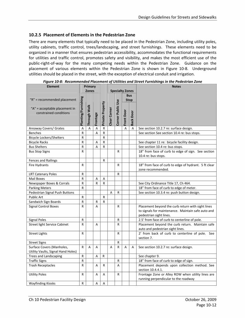
10.2.5 Placement of Elements in the Pedestrian Zone There are many elements that typically need to be placed in the Pedestrian Zone, including utility poles, utility cabinets, traffic control, trees/landscaping, and street furnishings. These elements need to be organized in a manner that ensures pedestrian accessibility, accommodates the functional requirements for utilities and traffic control, promotes safety and visibility, and makes the most efficient use of the public‐right‐of‐way for the many competing needs within the Pedestrian Zone. Guidance on the placement of various elements within the Pedestrian Zone is shown in Figure 10‐8. Underground utilities should be placed in the street, with the exception of electrical conduit and irrigation.
Figure 10‐8: Recommended Placement of Utilities and Street Furnishings in the Pedestrian Zone Primary Zones Specialty Zones
Bus Stop
Element
“R” = recommended placement
“A” = acceptable placement in constrained conditions
Plan
ting/Furnishing
Through Walk
Fron
tage
Private Prop
erty
Clear Co
rner
Corner Pub
lic Use
Fron
t Doo
r
Back Doo
r
Notes
Areaway Covers/ Grates A A A R A A See section 10.2.7 re: surface design. Benches R A R See section See section 10.4 re: bus stops. Bicycle Lockers/Shelters R R Bicycle Racks R A R See chapter 11 re: bicycle facility design. Bus Shelters R A R See section 10.4 re: bus stops. Bus Stop Signs R R 18” from face of curb to edge of sign. See section
10.4 re: bus stops. Fences and Railings R Fire Hydrants R R 18” from face of curb to edge of hydrant. 5 ft clear
zone recommended. LRT Catenary Poles R R Mail Boxes R A A Newspaper Boxes & Corrals R R R See City Ordinance Title 17, Ch 464. Parking Meters R 18” from face of curb to edge of meter. Pedestrian Signal Push Buttons A R See section 10.3.4 re: push button design. Public Art R R Sandwich Sign Boards R R R Signal Control Boxes R A R Placement beyond the curb return with sight lines
to signals for maintenance. Maintain safe auto and pedestrian sight lines.
Signal Poles R R 2.5’ from face of curb to centerline of pole. Street light Service Cabinet R A R Placement beyond the curb return. Maintain safe
auto and pedestrian sight lines. Street Lights R R 2’ from back of curb to centerline of pole. See
section 7. Street Signs R Surface Covers (Manholes, Utility Vaults, Signal Hand Holes)
R A A A R A A See section 10.2.7 re: surface design.
Trees and Landscaping R A R See chapter 9. Traffic Signs R R 18” from face of curb to edge of sign. Trash Receptacles R A R A Placement depends upon collection method. See
section 10.4.4.1. Utility Poles R A A R Frontage Zone or Alley ROW when utility lines are
running perpendicular to the roadway Wayfinding Kiosks R A A
Design Guidelines for Streets and Sidewalks
Ch 10 Pedestrian Facility Design October 26, 2009 Page 10‐13
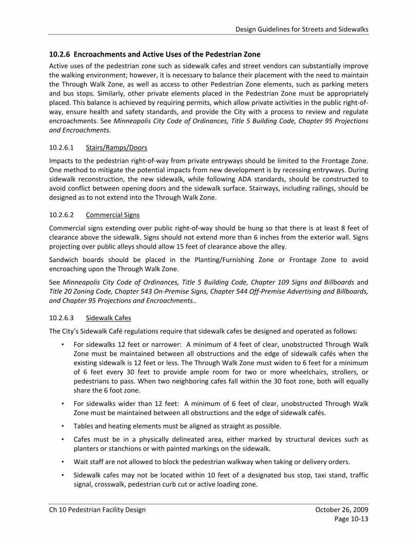
10.2.6 Encroachments and Active Uses of the Pedestrian Zone Active uses of the pedestrian zone such as sidewalk cafes and street vendors can substantially improve the walking environment; however, it is necessary to balance their placement with the need to maintain the Through Walk Zone, as well as access to other Pedestrian Zone elements, such as parking meters and bus stops. Similarly, other private elements placed in the Pedestrian Zone must be appropriately placed. This balance is achieved by requiring permits, which allow private activities in the public right‐of‐way, ensure health and safety standards, and provide the City with a process to review and regulate encroachments. See Minneapolis City Code of Ordinances, Title 5 Building Code, Chapter 95 Projections and Encroachments.
10.2.6.1 Stairs/Ramps/Doors
Impacts to the pedestrian right‐of‐way from private entryways should be limited to the Frontage Zone. One method to mitigate the potential impacts from new development is by recessing entryways. During sidewalk reconstruction, the new sidewalk, while following ADA standards, should be constructed to avoid conflict between opening doors and the sidewalk surface. Stairways, including railings, should be designed as to not extend into the Through Walk Zone.
10.2.6.2 Commercial Signs
Commercial signs extending over public right‐of‐way should be hung so that there is at least 8 feet of clearance above the sidewalk. Signs should not extend more than 6 inches from the exterior wall. Signs projecting over public alleys should allow 15 feet of clearance above the alley.
Sandwich boards should be placed in the Planting/Furnishing Zone or Frontage Zone to avoid encroaching upon the Through Walk Zone.
See Minneapolis City Code of Ordinances, Title 5 Building Code, Chapter 109 Signs and Billboards and Title 20 Zoning Code, Chapter 543 On‐Premise Signs, Chapter 544 Off‐Premise Advertising and Billboards, and Chapter 95 Projections and Encroachments..
10.2.6.3 Sidewalk Cafes
The City’s Sidewalk Café regulations require that sidewalk cafes be designed and operated as follows:
• For sidewalks 12 feet or narrower: A minimum of 4 feet of clear, unobstructed Through Walk Zone must be maintained between all obstructions and the edge of sidewalk cafés when the existing sidewalk is 12 feet or less. The Through Walk Zone must widen to 6 feet for a minimum of 6 feet every 30 feet to provide ample room for two or more wheelchairs, strollers, or pedestrians to pass. When two neighboring cafes fall within the 30 foot zone, both will equally share the 6 foot zone.
• For sidewalks wider than 12 feet: A minimum of 6 feet of clear, unobstructed Through Walk Zone must be maintained between all obstructions and the edge of sidewalk cafés.
• Tables and heating elements must be aligned as straight as possible.
• Cafes must be in a physically delineated area, either marked by structural devices such as planters or stanchions or with painted markings on the sidewalk.
• Wait staff are not allowed to block the pedestrian walkway when taking or delivery orders.
• Sidewalk cafes may not be located within 10 feet of a designated bus stop, taxi stand, traffic signal, crosswalk, pedestrian curb cut or active loading zone.

Design Guidelines for Streets and Sidewalks
Ch 10 Pedestrian Facility Design October 26, 2009 Page 10‐14
• A minimum vertical height of 6’6” must be maintained between the sidewalk and the lowest edge of table umbrellas or awnings if the umbrella or awning extends over the edge of the café boundary.
In addition to these standards, the following guidelines are recommended:
• The Through Walk Zone widths recommended in section 10.2.1 and Figure 10‐7 are wider than the existing sidewalk café regulations. These wider widths should be used when possible, particularly in activity centers and other locations with high pedestrian activity.
• A straight and continuous Through Walk Zone from one end of the block to the other should be maintained to the greatest extent possible.
• Fencing around sidewalk cafes should be in compliance with PROWAG guidelines (R302.4) and MUTCD standards. Fences should be continuous, stable and rigid. A continuous edge should be provided no more than 6 inches from the ground, and an upper rail should be provided at a minimum of 3 feet above the ground. Support members should not protrude into the Through Walk Zone.
• The placement of sidewalk cafes must be managed. Sidewalk cafes are mobile objects and may encroach upon the Through Walk Zone if not properly managed. The City’s Regulatory Services Department enforces the sidewalk café ordinance.
See Minneapolis City Code of Ordinances, Title 13 Licenses and Business Regulations, Chapter265. Special Permits for Specific Businesses and Uses, Article VII Sidewalk Cafes.
10.2.6.4 Street Vendors
Street vendors, such as those on Nicollet Mall add to the liveliness of the street. Street vendors should be allowed in activity centers, neighborhood commercial nodes, and community and commercial corridors wherever the width of the Pedestrian Zone allows. Vending should take place in the Planting/Furnishing Zone and not encroach upon the Through Walk Zone. A minimum of four feet of clear unobstructed pedestrian Through Walk Zone must be provided around street vendor stands, and the recommended widths recommended in section 10.2.1 and Figure 10‐7 should be used when possible, particularly in activity centers.
See Minneapolis City Code of Ordinances, Title 13 Licenses and Business Regulations, Chapter 323 Peddlers and Chapter 331 Sidewalk Flower Cart Vendors.
10.2.7 Sidewalk Surface Design The Through Walk Zone should provide a safe and accessible surface for walking, rolling wheelchairs, and people using walkers, crutches and walking canes. Sidewalks should be level, firm, stable and slip resistant and avoid excessive vibrations for wheelchair users.
10.2.7.1 Material and Surface Finish
The standard sidewalk material in Minneapolis is concrete pavement. This material is used on the majority of sidewalks in Minneapolis, and typical sidewalk panel sizes are approximately 6 x 6 feet. In some cases, however, it may be desirable to enhance the streetscape by using enhanced paving materials such as scored sidewalks, pavers, colored concrete, stone or other approved paving material.
Enhanced paving materials often have more frequently‐spaced joints that can create uncomfortable or painful vibrations for wheelchair users if pavers are not properly constructed or maintained. PROWAG advises:

Design Guidelines for Streets and Sidewalks
Ch 10 Pedestrian Facility Design October 26, 2009 Page 10‐15
Surfaces with individual units laid out of plane and those that are heavily textured, rough, or chamfered, will greatly increase rolling resistance and will subject pedestrians who use wheelchairs, scooters, and rolling walkers to the stressful (and often painful) effects of vibration. It is highly desirable to minimize surface discontinuities; when discontinuities on the pedestrian access route are unavoidable, they should be widely separated. (PROWAG R301.5)
Therefore, when selecting a design and material for sidewalk surfaces, the following must be considered:
• Surface Discontinuities – Surface discontinuities may not exceed ½ inch maximum (openings should not permit the passage of a ½ inch sphere), and vertical discontinuities between ¼ and ½ inch maximum must be beveled at 1:2 minimum (PROWAG R301.5), as shown in Figure 10‐9.
• Mn/DOT Construction Specifications ‐ Mn/DOT standard specifications require that joints between panels be formed with a ¼ inch rounding tool and that sidewalk surfaces be constructed with a maximum 3/16 inch variation in surface over a 10 foot plane.
• Panel/Paver Size – The more frequently‐spaced the joints between paver units or sidewalk panels, the more opportunities there are for excessive surface discontinuities to be present at the time of construction or to develop over time. Larger panel sizes generally ensure a more comfortable and accessible surface for all pedestrians. Smaller decorative pavers that add architectural detail may be placed at the edges of the Through Walk Zone, thereby minimizing potential excessive vibrations for wheelchair users, while also improving the aesthetic design as shown in Figure 10‐10.
• Material ‐ Material must be slip‐resistant and durable and resistant to chipping, breakage, deterioration, or corrosion resulting from snow removal equipment and solvents. Some stone pavers are more slippery in wet or icy conditions than concrete.
• Cost ‐ Special paving materials generally have higher initial costs, as well as long‐term maintenance costs.
• Decorative Scoring – Concrete sidewalks may be enhanced with a decorative design by scoring smaller panel sizes and finishing the edge of each panel with a smooth border instead of a continuous broom finish (see Figure 10‐10). Decorative scoring must be carefully constructed to minimize the surface discontinuities not only between scored sidewalk panels, but also between the smoothed border and broom finish within each panel.
• Stamped and Etched Designs – Concrete sidewalks may also be stamped or etched with designs, as shown in Figure 10‐11. As with decorative scoring, stamped and etched designs must be carefully designed and constructed to minimize surface discontinuities. Stamped and etched designs are typically placed on only a few sidewalks panels per block, which helps to minimize surface discontinuities.
See Special Provisions for the Construction of Concrete Sidewalks, Curb and Gutter, Alleys and Drive Approaches for design standards.
See also Section 10.5.3.5 Textured and Colored Pavement Crosswalks.

Design Guidelines for Streets and Sidewalks
Ch 10 Pedestrian Facility Design October 26, 2009 Page 10‐16
Figure 10‐9: Maximum Surface Discontinuities
Source: NvDOT Field Guide for Accessible Public Rights of Way
Figure 10‐10: Decorative Sidewalk Scoring and Pavers in the Planting/Furnishing Zone
Location: Marquette Avenue S
Figure 10‐11: Stamped Sidewalk Design
Location: Franklin Avenue

Design Guidelines for Streets and Sidewalks
Ch 10 Pedestrian Facility Design October 26, 2009 Page 10‐17
10.2.7.2 Sidewalk Grade and Cross‐Slope
Sidewalk running grade should be no greater than 5% unless the public sidewalk is following a public street with a running grade greater than 5%. Sidewalks should slope towards the curb to allow for stormwater drainage. The cross slope on the Through Walk Zone should be no greater than 2%.
To achieve an acceptable cross‐slope in locations with exceptional topographic conditions, the Planting/Furnishing Zone and Frontage Zone may have a steeper cross‐slope as long as the 2% cross‐slope is maintained for the minimum Through Walk Zone width, as shown in Figure 10‐12. Allow enough space for the opening of parked car doors. The exception to this design is at transit stops, which require a level loading area (see section 10.4.2.1).
See Special Provisions for the Construction of Concrete Sidewalks, Curb and Gutter, Alleys and Drive Approaches for more City standards.
Figure 10‐12: Sidewalk Cross‐Slope
Source: Santa Barbara Pedestrian Master Plan
10.2.7.3 Grates
Areaway ventilation grates, tree grates, and other types of grates which serve as a walkable surface within the Pedestrian Zone should be designed as follows:
• Openings should not allow the passage of a ½ inch sphere; and
• Openings should be oriented so that the long dimension is perpendicular or diagonal to the dominant direction of travel.
10.2.8 Driveway, Alley, & Railroad Crossings of Sidewalks Driveway and alley entrances and railroad crossings expose pedestrians to potential hazards.
10.2.8.1 Driveways and Alleys
• Sidewalk Width and Grade ‐ The width and grade of the Through Walk Zone should continue across driveways and alleys as shown in Figure 10‐13, consistent with the recommended widths in section 10.2.1.2 (6 feet recommended, 5 feet acceptable). Driveways over the Through Walk Zone of sidewalks may not exceed a 2 percent cross slope. The ramp portion of a driveway entrance should be located within the Curb and Planting/Furnishing Zone wherever possible. The grade of driveway entrances in the Curb and Planting/Furnishing Zone may not exceed a 12 percent grade. In existing constrained conditions, the Through Walk Zone width may be reduced to 4 feet, and the sidewalk may be jogged back, as shown in Figure 10‐13. The slope of driveways for the first 20’ behind the public right‐of‐way should not exceed 4 percent.

Design Guidelines for Streets and Sidewalks
Ch 10 Pedestrian Facility Design October 26, 2009 Page 10‐18
Figure 10‐13: Sidewalk Driveway and Alley Crossings
DESIRABLE: Through Walk Zone maintained across driveway.
ACCEPTABLE: Jogged sidewalk.
Note that Minneapolis standard curb design uses returned, not flared edges, as
shown in this image.
UNACCEPTABLE: Driveway cuts through the Through Walk Zone creating accessibility problems.
Source: Designing Sidewalks and Trails for Access, FHWA.
• Access Management ‐ Driveway entrances to buildings should be consolidated whenever possible to reduce the frequency of curb cuts on any given block face. Less frequent spacing will minimize vehicle conflicts with pedestrians on sidewalks as shown in Figure 10‐14 and will provide more space for street furniture, street trees, and lighting, as well as street parking.
Figure 10‐14: Benefits of Access Management for Pedestrians
Source: Guide for the Planning, Design, and Operation of Pedestrian Facilities, AASHTO.
• Driveway and Alley Width ‐ Driveway and alley widths should be minimized to reduce entrance speeds, maximize landscaping opportunities, and reduce pedestrian exposure at vehicle access points. Driveways widths are regulated by Chapter 541, Off‐Street Parking and Loading in the zoning code and vary by zoning district; the minimum driveway width is typically 12 feet, and the maximum driveway width is typically 25 feet. New alleys should be a minimum of 14 feet unless they are reconstructing an existing condition, where they can be a minimum of 12 feet wide.
• Driveway Location ‐ Driveways should be located away from intersections in order to minimize conflicts with pedestrians at corners and in crosswalks. Driveways should be a minimum of 30 feet clear of the intersection of two major streets and a minimum of 20 feet from all other

Design Guidelines for Streets and Sidewalks
Ch 10 Pedestrian Facility Design October 26, 2009 Page 10‐19
intersections. Driveways are discouraged for residential properties with access to an alley, except on corner lots, where the driveway curb cut can be located from the side yard.
• Parking Ramp and Vehicular Building Access/Egress – Access to and egress from parking ramps should be designed perpendicular to the street in a single curb cut, as shown in Figure 10‐15. This design promotes good visibility between pedestrians and vehicles and minimizes potential conflict points between pedestrians and vehicles. In large developments, it is recommended that vehicular curb cuts be located midblock and be limited to one curb cut per block face.
Figure 10‐15: Parking Ramp Access/Egress
Source: Down East/North Loop Master Plan
• Other Considerations ‐ Parked cars should not block the sidewalk crossing driveways.
See Special Provisions for the Construction of Concrete Sidewalks, Curb and Gutter, Alleys and Drive Approaches for more information.
10.2.8.2 At‐Grade Railroad Crossings
When not properly designed, rail crossings can be barriers to wheelchairs, strollers, carts, and other wheeled items used by pedestrians, as shown in Figure 10‐16, and can encourage pedestrians to walk in the street across railroad tracks. There are several existing railroad crossings in Minneapolis that have concrete sidewalks on both side of the tracks, but ballasted track or crumbling asphalt across the tracks.
Figure 10‐16: Wheelchair Wheel Stuck in Flangeway
Source: Rail Reflections Magazine, Issue 18, Transportation Safety Board of Canada.
Where sidewalks are needed on both sides of a railroad crossing, a continuous sidewalk with a firm and stable surface must be provided. It is also recommended that the Planting/Furnishing Zone be carried

Design Guidelines for Streets and Sidewalks
Ch 10 Pedestrian Facility Design October 26, 2009 Page 10‐20
across the railroad crossing to separate the street crossing from the pedestrian crossing and prevent vehicles from driving on the sidewalk, as shown in Figure 10‐17; this is particularly important at multi‐track railroad crossings where crossings are long.
Figure 10‐17: Planting/Furnishing Zone across Railroad Crossing
Location: 11th Avenue NE; Source: Google Streetview
Openings for wheel flanges at pedestrian crossings of railroad tracks should be designed to prevent wheelchair wheels from becoming stuck in the tracks. Additional guidance on rail crossing design is available in the PROWAG.
10.2.9 Sidewalks on Bridges Bridges provide pedestrians with connections across major barriers, such as rivers, freeways, railroads, and creeks. Because bridges are expensive to construct and maintain, they are much less frequently spaced than the rest of the street and sidewalk network. Bridges are essential connections in areas with otherwise poor pedestrian connectivity and must be designed to provide safe, comfortable and appealing pedestrian connections.
Bridges can present particular challenges in providing a pedestrian zone that is adequately sized, safe and attractive for pedestrians. Many bridges in Minneapolis have been built with minimal sidewalk space (typically 5‐8 feet), and some have sidewalks on only one side. Bridges often have wide vehicle lanes and a wide shoulder, typically matching the width of approaching streets. Unlike on street approaches to bridges where on‐street parking helps to buffer pedestrians from traffic and provide some side friction to slow vehicle speeds, pedestrians are unprotected from fast moving vehicles. In addition, bridges do not have the benefit of adjacent land uses, which provide “eyes on the street” and lighting to provide pedestrians with a sense of personal security.
10.2.9.1 Pedestrian Zone Organization and Widths
Pedestrian facilities on bridges have the same organization and functional needs for the pedestrian zone as do pedestrian facilities on streets (see section 10.2.1). The organization and width of the pedestrian zone on bridges is as follows:
• Curb/Furnishings Zone – The Curb and Planting/Furnishing Zones are combined on bridges. This zone provides a buffer between the roadway and the Through Walk Zone, space for temporary snow storage on bridges, and space for signage. It also provides a curb to discourage vehicles from driving onto the sidewalk. Because most bridges do not have on‐street parking to buffer pedestrians from moving traffic, it is essential that this zone provide sufficient width to buffer pedestrians from moving traffic. The width of this zone should be a minimum of 2 feet wide. On longer bridges, which typically have higher vehicle operating speeds, this zone may need to

Design Guidelines for Streets and Sidewalks
Ch 10 Pedestrian Facility Design October 26, 2009 Page 10‐21
be wider or a barrier rail provided. Additional width will also be required if seasonal plantings and/or street furnishings are desired on the bridge.
• Through Walk Zone – This zone provides an accessible clear walking space for pedestrians, as well as bicyclists who prefer to ride on sidewalks.3 As shown in Figure 10‐18, the recommended Through Walk Zone on bridges is 8 feet on non‐local street types and 6 feet on local street types. (See section 2.2 for more information on street design types.) Bridges that connect to multi‐use trails often serve bicyclists who do not feel comfortable riding in on‐street bike lanes. If the bridge connects to a multi‐use trail, as do many of the Mississippi River bridges, the Through Walk Zone should be a minimum of 10 feet wide.
• Frontage Zone – This zone reflects the tendency of people to shy away from the precipice of a bridge. It should be a minimum of 2 feet wide.
It should be noted that the necessary width for snow clearance equipment on bridge sidewalks is typically 8‐9 feet.
Figure 10‐18: Minimum Pedestrian Zone Width on Bridges Type of Bridge Curb/Furnishing
Zone Through Walk
Zone Frontage Zone
Total Width
Bridge on Local Street Design Type 2’ 6’ 2’ 10’ Bridge on Non‐Local Street Design Types 2’ 8’ 2’ 12’ Bridge Connecting to Multi‐Use Trail 2’ 10’ 2’ 14’
See section 2.2 for more information on street design types.
10.2.9.2 Lighting
Bridges do not have the benefit of light coming from adjacent land uses such as store fronts and residences. In addition to lighting for vehicle movement, all bridges with pedestrian facilities should have pedestrian‐scaled lighting to provide a safe pathway. Lighting may be placed in the Planting/Furnishing Zone if appropriate Through Walk Zone widths and space for snow clearance equipment can be maintained, or it may be incorporated into bridge railings/fencing. Lighting placed on the inside of the sidewalk, as shown in Figure 10‐19, instead of the outside railing, helps define the separation between roadway and pedestrian facilities.
10.2.9.3 Barriers from Traffic
Longer bridges that promote higher vehicle speeds and bridges along arterial routes should provide a barrier from traffic to give pedestrians a sense of enclosure and safety. The Federal Highway Administration recommends a railing or barrier measuring at least 42 inches in height for roads with heavy traffic or high speeds, although Mn/DOT allows barriers of 36 inches, see Figure 10‐19. The barrier styles chosen should match the site and context of the bridge.
10.2.9.4 Railings
The outside railings on bridges should be well‐designed to provide an appealing pedestrian environment, as shown in Figure 10‐19. Use of chain‐link fence on bridges is not recommended. On bridges where bicycles may legally ride on the sidewalk (all sidewalks outside business districts), a 54 inch high railing should be used to protect bicyclists from falling over the edge of the bridge.
3 Bicyclists are permitted sidewalk users outside of business districts under state statute.

Design Guidelines for Streets and Sidewalks
Ch 10 Pedestrian Facility Design October 26, 2009 Page 10‐22
Figure 10‐19: Example of Pedestrian Barrier and Pedestrian Scale Lighting on Bridge
Location: Lake Street bridge over the Mississippi River
10.2.9.5 Visibility
Pedestrian facilities on bridges must be designed to provide adequate sight lines between pedestrians and vehicles at intersections at the ends of bridges. High fencing and overgrown vegetation should be avoided.
10.2.9.6 Retrofitting pedestrian improvements on bridges
Many existing bridges in Minneapolis have narrow sidewalks and a shoulder lane that is the same width as the parking lane on the approaching street. In most circumstances, parking is restricted on bridges, so a parking lane is not needed, but a shoulder for disabled vehicles is usually required.4 The shoulder may typically be 6 feet wide on either side of the bridge, which also provides space for a bike lane; it does not need to be the full width of a typical parking lane. This provides an opportunity to retrofit many bridges to widen sidewalks and narrow the vehicle shoulder within the existing bridge width. Where the approaching street on either side of the bridge has a parking lane, curb extensions may be constructed to match the curb line of the street with the curb line of the bridge, as shown in Figure 10‐20.
Figure 10‐20: Conceptual Bridge Design
Source: I‐35W Access Project
4 There may be some circumstances on very short bridges where a shoulder for disabled vehicles is not needed.

Design Guidelines for Streets and Sidewalks
Ch 10 Pedestrian Facility Design October 26, 2009 Page 10‐23
10.2.10 Sidewalks under Bridges Pedestrian facilities under bridges are often unappealing pedestrian environments due to poor lighting, blocked sight lines, narrow sidewalks, and bridge pier design that create locations for people to hide. In addition, under bridge environments do not have the benefit of adjacent land uses that provide “eyes on the street.” Real and perceived personal security is significant concern in under bridge environments.
The principles of Crime Prevention Through Environmental Design (CPTED) should be applied to the design of pedestrian facilities under bridges, and the creation of entrapment or habitation areas should be avoided. Pedestrian facilities under bridges should be designed with adequate physical space for pedestrians, proper lighting, clear sight lines, and architectural treatments that create an inviting, human‐scaled pedestrian environment.
10.2.10.1 Pedestrian Zone Organization and Widths
Pedestrian facilities under bridges have the same organization and functional needs for the pedestrian zone as do pedestrian facilities on streets. The organization and width of the pedestrian zone under bridges is the same as that shown for streets in section 10.2.1. The total width should be a minimum of 12 feet.
10.2.10.2 Pier Design and Placement
The design and placement of bridge piers should provide good visibility between the street and the sidewalk and avoid creation of hiding places where criminals could lurk unseen.
10.2.10.3 Retaining Wall Design
The design of retaining walls under bridges should incorporate design treatments to create a pedestrian scale environment.
10.2.10.4 Lighting
Lighting is paramount to how safe pedestrians feel traveling under bridges. Sidewalks under bridges should have pedestrian‐scaled lighting. Pedestrian lighting under bridges can be an opportunity for a community gateway though public art or architectural lighting. Exclusive use of utilitarian “wallpaks” should be avoided. See Section 7 for further guidance on City’s Lighting Policy.
10.2.10.5 Snow and Ice Clearance
Sidewalks under bridges do not have the benefit of sunlight to melt snow and ice. They must be designed to minimize snow and ice accumulation, and they must be maintained to ensure proper snow and ice clearance.
10.3 STREET CORNERS Pedestrian activities are often concentrated at street corners. Corners are where the transition between sidewalk grade and crosswalk grade are made for wheelchair users. Corners are where pedestrians meet, wait to cross or for a bus, and often stop to talk. Each corner of an intersection should be analyzed to determine the best design given the various conditions that exist at each intersection corner along a corridor.
Unfortunately, other design considerations sometimes erode the space available for pedestrian activities at corners, because many other elements are placed at corners, such as traffic signal poles, fire

Design Guidelines for Streets and Sidewalks
Ch 10 Pedestrian Facility Design October 26, 2009 Page 10‐24
hydrants, and traffic signal control boxes. Additionally, turning vehicles can erode the corner space by requiring larger turning radii.
10.3.1 Elements of Good Corner Design Good corners exhibit the following attributes:
• Clear Space: Corners should be clear of obstructions, and have enough space to accommodate the number of pedestrians for the site conditions. For example, activity centers, neighborhood commercial nodes, and community and commercial corridors require more pedestrian space than neighborhood intersections. They should also have enough room for curb ramps, for transit stops where appropriate, and for social interaction.
• Visibility: It is critical that pedestrians, cyclists and motorists have a good view of each other at intersections.
• Legibility: Symbols, marks, and signs used at corners should clearly indicate what actions the pedestrian, cyclists, and motorists are expected to take.
• Accessibility: All corner design features shall meet accessibility standards.
10.3.1.1 Corner Space
The most desirable corner condition for pedestrians is a wide pedestrian zone and small corner radius. This scenario provides the most corner space and makes it easy to align the sidewalks, curb ramps and crosswalks, which provides the most direct and likely path of travel for pedestrians, minimizes the likelihood of pedestrians crossing outside of the crosswalk, and minimizes the maneuvering that wheelchair users must perform to use the ramp, as shown in Figure 10‐21.
Figure 10‐21: Relationship between Corner Space, Corner Radius, and Pedestrian Zone Width
DESIRABLE:
‐ wide pedestrian zone ‐ small corner radius ‐ ample corner space ‐ straight path of travel
UNDESIRABLE:
‐ narrow pedestrian zone ‐ large corner radius ‐ little corner space
‐ indirect path of travel
10.3.1.2 Visibility at Corners
It is critical that pedestrians at the corner have a good view of the travel lanes and that motorists in the travel lanes can easily see waiting pedestrians. Visibility between motorists and pedestrians is often impeded by parked vehicles near the intersection. Visibility may also be impeded by other vertical elements, such as buildings, fences, hedges and walls.
Current parking ordinances restrict parking within the vicinity of intersections as a way to increase the visibility of pedestrians. Minneapolis ordinance prohibits on‐street parking near intersections as follows:
• Within 20 feet of a legal pedestrian crossing (whether marked or unmarked) at an intersection.

Design Guidelines for Streets and Sidewalks
Ch 10 Pedestrian Facility Design October 26, 2009 Page 10‐25
• Within 30 feet of the approach of any flashing school signal stop sign, traffic‐control signal, or school sign at the side of a roadway.
• Within 5 feet of an alleyway or driveway.
Curb extensions (see section 10.3.5) are an excellent technique for increasing visibility particularly for shorter pedestrians, such as wheelchair users and children, because they physically restrict parking near intersections. Thus curb extensions do not remove parking, but simply formalize it.
Visibility can also be impeded by wide corner radii, which place curb ramps and sidewalks further back from the intersection. Tighter turning radii can improve visibility in some instances (see section 10.3.2).
See Minneapolis City Code of Ordinances, Title 18 Traffic Code, Chapter 478 Parking, Stopping, and Standing.
10.3.2 Curb Return or Corner Radii The curb return is the curved connection of curbs where two streets come together to form an intersection. The purpose of the curb return is to guide vehicles in turning corners and to separate vehicular traffic from pedestrian areas at intersection corners. Large curb radii allow motorists to maintain a high speed while turning right, which puts pedestrians at risk. Reduced corner radii force vehicles to slow down. In general, the smallest practical curb return radii should be used at city intersections to provide adequate space for properly aligned curb ramps, shorten the length of pedestrian crosswalks, manage the speed of turning vehicles, and provide adequate space at the corner for curb ramps.
See Section 5.8.1, Curb Return or Corner Radii for more information about corner radii. In addition to the guidance in section 5.8.1, where turning movements are prohibited, such as at one‐way streets, a tight (5 foot) corner radius should be used.
10.3.3 Curb Ramps Access for people with disabilities is critical to an interconnected and continuous pedestrian system and curb ramps are one of the key design features that make sidewalks accessible. Curb ramps provide access for people, such as those who use wheelchairs or other mobility aids, who would otherwise be excluded from the sidewalk because of the barrier created by the curb. This accessibility extends to many other sidewalk users, including parents with strollers/wagons, children on bicycles, adults with rolling luggage, elderly pedestrians walking to/from stores with collapsible grocery carts, and those using walkers, etc.
10.3.3.1 Number of Ramps
Curb ramps must be provided at all legal crossings. At a typical intersection, there should be two curb ramps at each corner, regardless of traffic control. Use of small turning radii and curb extensions can help to accommodate two curb ramps at each corner. In some circumstances, it may not be possible to fit two curb ramps, depending upon corner radius and sidewalk width, and, although least desirable, a single diagonal ramp must be used.
10.3.3.2 Types of Curb Ramps
There are a variety of curb ramp design options, the basics of which are shown in Figure 10‐25. In general, the most desirable configuration for curb ramps is to have curb ramps placed perpendicular to the curb and aligned with the direction of travel, as shown in Figure 10‐25, Curb Ramp Types 1 and 2. This provides continuity in the direction of travel that helps to guide visually impaired pedestrians across

Design Guidelines for Streets and Sidewalks
Ch 10 Pedestrian Facility Design October 26, 2009 Page 10‐26
the intersection and is convenient and efficient to all pedestrians. This also benefits drivers as they know to expect which direction pedestrians will travel. Curb ramps in line with the direction of travel also add to an orderly appearance to the streetscape. However, because it is not always possible to provide two perpendicular ramps, Figure 10‐25 also provides several other design options for curb ramps in more constrained conditions.
The Mn/DOT standard curb ramp template, which the City uses, does not currently allow for all of these curb ramp types. Additional design options such as those shown in Figure 10‐25 are needed to accommodate accessible curb ramps on typical Minneapolis corners. The current design standard requires 10 feet from the face of curb to the back of ramp landing, which is more space than exists on many Minneapolis corners.
10.3.3.3 Technical Details
The current PROWAG guidelines recommend the following design dimensions for the curb ramp components shown in Figure 10‐22:
• Ramp Running Slope: 5.0% minimum and 8.3% maximum on perpendicular and parallel ramps not to exceed 15.0 foot ramp length; 5.0% maximum on blended transitions
• Ramp Cross Slope: 2% maximum
• Ramp Width: 4.0 foot minimum (It is desirable to maintain the same width as the Through Walk Zone.)
• Landing Dimensions: 4.0 x 4.0 foot minimum
• Landing Cross Slope: 2% maximum
• Flared Side Cross Slope: 10% maximum
Returned Edges: Flared sides are not required. Returned edges as shown in Source: Designing Sidewalks and Trails for Access, FHWA.
• Figure 10‐23 can aid in aligning curb ramps with sidewalks and crosswalks and aid in wayfinding for visually impaired people. Returned edges may be used if protected from cross travel by turf grass, landscaping, street furniture, or other vertical obstruction.
• Gutter Counter Slope: 5% maximum
• Detectable Warnings: Required on all ramps
• Clear Space at Ramp Bottom: 4.0 x 4.0 foot minimum (free of vehicle movement)
Figure 10‐22: Curb Ramp Components
Source: Designing Sidewalks and Trails for Access, FHWA.

Design Guidelines for Streets and Sidewalks
Ch 10 Pedestrian Facility Design October 26, 2009 Page 10‐27
Figure 10‐23: Curb Ramp with Returned Edges
Source: Accessible Public Rights‐of‐Way: Planning and Designing for Alterations, ITE, July 2007
10.3.3.4 Drainage
The designer should ensure that stormwater drains should be on the upstream side of the curb ramp to reduce the potential for pools at the ramp. The gutter slope should be designed to direct water across ramp landings to avoid pooling at the bottom of the curb ramp.
10.3.3.5 Obstructions
Curb ramps and crosswalks must remain clear of obstacles. Existing obstructions in curb ramps should be moved as opportunities and budgets allow. No new pole, utility or other impediment should be placed in the curb ramp return areas.
10.3.3.6 Solutions for Constrained Conditions
There are many constrained corner conditions in Minneapolis that make it very difficult to fit two perpendicular curb ramps per corner. In these cases, it may be necessary to use curb extensions, tighter corner radii or to a combination parallel and perpendicular ramp, as shown in Figure 10‐24.
Figure 10‐24: Curb Ramp Solutions for Constrained Conditions
Source: Accessible Public Rights‐of‐Way: Planning and Designing for Alterations, ITE, July 2007

Design Guidelines for Streets and Sidewalks
Ch 10 Pedestrian Facility Design October 26, 2009 Page 10‐28
Figure 10‐25: Curb Ramp Types
1. Perpendicular Ramps on Tangent Pros: ‐ Ramp is in line with Through Walk Zone and crosswalk. ‐ Aids snow clearing because plows travel straight along edge of ramp. ‐ Optional returned edge next to planted boulevard reduces impervious surface, allows placement next to vertical obstructions, and aids wayfinding for visually impaired users. Cons: ‐ Requires sufficient physical space – typically 10 feet behind the curb ‐ which requires a small curb radius and/or large Pedestrian Zone.
DESIRABLE
2. Directional Ramps on Radius Pros: ‐ Ramp is in line with Through Walk Zone and crosswalk. ‐ Accommodates wider radius and/or narrower Pedestrian Zone than type #1. ‐ Aids snow clearing because plows travel straight along edge of ramp. ‐ Optional returned edge next to planted boulevard reduces impervious surface, allows placement next to vertical obstructions, and aids wayfinding for visually impaired users. Cons: ‐ More complicated grade requirements to provide level landing at ramp bottom.
DESIRABLE
3. Dual Diagonal Ramps (Perpendicular Ramps on Radius) Pros: ‐ Accommodates wider radius and/or narrower Pedestrian Zone than types #1 & 2. ‐ Can be built on corners of any radius and along Pedestrian Zones of any width. Cons: ‐ May require additional right of way behind typical sidewalk intersection for necessary grades. ‐ Curb ramps do not align with the direction of travel. ‐ Snow plows more likely to leave wedge of snow in front of ramps and can be difficult for property owners to locate ramps under snow for clearance.
ACCEPTABLE
4. Parallel Ramps Pros: ‐ Easier to fit in constrained conditions. Cons: ‐ Curb ramps do not align with the direction of travel. ‐ Multiple grade changes are required in the Through Walk Zone.
ACCEPTABLE
5. Blended Transition Pros: ‐ Easier to fit in constrained conditions. ‐ Ramp is in line with the Through Walk Zone. Cons: ‐ Lack of a raised curb may encourage vehicles to drive onto the curb ramp. ‐ Curved truncated dome plate not available in cast iron, Mn/DOT approved material. ‐ Although ramp is in line with Through Walk Zone, diagonal travel is possible. ‐ Requires crosswalk markings closer to intersection. ‐ Landing at‐grade with gutter increases potential for pooling and debris accumulation. ‐ Snow plows leave wedge of snow in front of ramp.
ACCEPTABLE
6. Single Diagonal Pros: ‐ Easier to fit in constrained conditions. Cons: ‐ Curb ramps do not align with the direction of travel. ‐ Provides unclear information to drivers of pedestrians’ crossing intentions. ‐ Wheeled users are steered to the center of the intersection and need to make a directional adjustment in the roadway. ‐ Requires crosswalk markings closer to intersection. ‐ May not allow proper spacing for pedestrian signals. ‐ Snow plows leave wedge of snow in front of ramp.
UNDESIRABLE
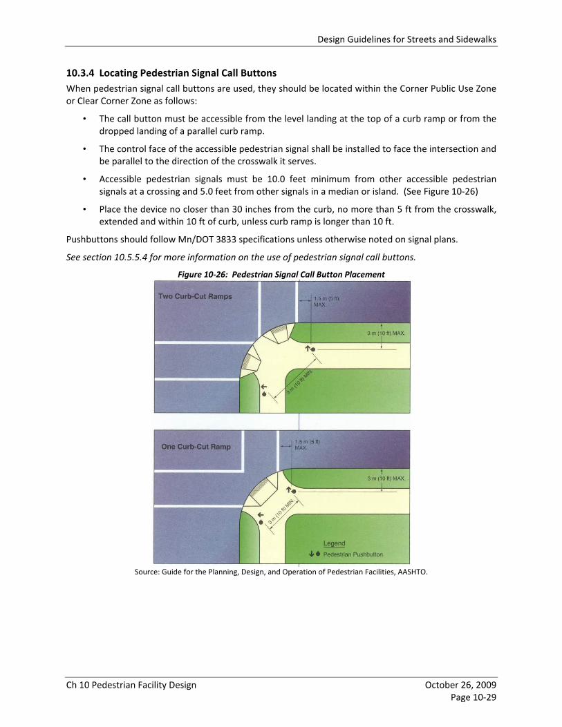
Design Guidelines for Streets and Sidewalks
Ch 10 Pedestrian Facility Design October 26, 2009 Page 10‐29
10.3.4 Locating Pedestrian Signal Call Buttons When pedestrian signal call buttons are used, they should be located within the Corner Public Use Zone or Clear Corner Zone as follows:
• The call button must be accessible from the level landing at the top of a curb ramp or from the dropped landing of a parallel curb ramp.
• The control face of the accessible pedestrian signal shall be installed to face the intersection and be parallel to the direction of the crosswalk it serves.
• Accessible pedestrian signals must be 10.0 feet minimum from other accessible pedestrian signals at a crossing and 5.0 feet from other signals in a median or island. (See Figure 10‐26)
• Place the device no closer than 30 inches from the curb, no more than 5 ft from the crosswalk, extended and within 10 ft of curb, unless curb ramp is longer than 10 ft.
Pushbuttons should follow Mn/DOT 3833 specifications unless otherwise noted on signal plans.
See section 10.5.5.4 for more information on the use of pedestrian signal call buttons.
Figure 10‐26: Pedestrian Signal Call Button Placement
Source: Guide for the Planning, Design, and Operation of Pedestrian Facilities, AASHTO.

Design Guidelines for Streets and Sidewalks
Ch 10 Pedestrian Facility Design October 26, 2009 Page 10‐30
10.3.5 Curb Extensions Curb extensions, which are also known as “bump‐outs, bulb‐outs, neckdowns, and chokers”, are an extension of the pedestrian zone into the on‐street parking lane. Curb extensions are typically used at intersections, but they may also be used at mid‐block locations.
10.3.5.1 Purpose
Curb extensions have many benefits, including:
• Improved sight lines between vehicles and pedestrians (see Figure 10‐27)
• Reduced crosswalk distance, thereby reducing pedestrian exposure to potential vehicle conflicts.
• Curb extensions can slow the speed of turning vehicles by decreasing turning radii and visually narrowing the roadway.
• Additional corner space to fit two perpendicular curb ramps per corner, utilities and traffic control, street furniture, trees and landscaping, transit facilities, bicycle parking, and sidewalk cafes.
• Additional pervious space for plantings and stormwater management.
Figure 10‐27: Safety Benefits of Curb Extensions
Source: Designing Sidewalks and Trails for Access, FHWA.
10.3.5.2 Locations
Curb extensions can be installed on all streets where on‐street parking is allowed. Specific priority areas for curb extensions include:
• New or reconstructed streets
• Streets where the pedestrian zone is less than 12 feet.
• Community and commercial corridors
• Wide streets with long crossing times
• Activity centers and neighborhood commercial nodes
• Primary Transit Network (PTN) streets
Although typically used at intersections, curb extensions may be used at midblock locations to provide additional sidewalk space for landscaping, bus shelters, seating, stormwater treatment, and bike parking, and improve pedestrian visibility and safety at mid‐block crossings, as shown in Figure 10‐28.

Design Guidelines for Streets and Sidewalks
Ch 10 Pedestrian Facility Design October 26, 2009 Page 10‐31
Figure 10‐28: Midblock Curb Extension
Location: Ann Arbor, Michigan
Although curb extensions have many benefits, they may not be appropriate in all circumstances. Curb extensions may have the following disadvantages:
• They may be more expensive to construct than alternative designs.
• They can reduce flexibility of the roadway in construction routing.
• They may cause traffic to queue behind a stopped bus, thus causing traffic congestion.
• They prevent the use of the parking lane during peak travel periods.
• They can reduce future flexibility in making changes to the location of bus zones, bike lanes, roadway lane layout, or crosswalks.
• They may result in traffic back‐up if the resulting through traffic, including left turns, is restricted to one lane so that left‐turning cars block through traffic.
10.3.5.3 Design
The design of curb ramps should account for the following:
• Width ‐ Curb extensions should be a minimum of 6 feet wide and be typically 2 feet narrower than the parking lane width, such that the curb and gutter of the curb extension is outside the vehicular travel lane or bicycle travel lane.
• Length ‐ Curb extensions should be at least 30 feet in length. This minimum is based on typical crosswalk dimensions (10‐15 feet) and ordinances requiring no parking 20 feet of a crosswalk or 30 feet of a stop sign. Additional length may be desired, depending on the furnishings and/or uses that need to be accommodated on the curb extension.
• Taper ‐ The taper length will be determined based on the quantity of on‐street parking stalls desired and snow removal/storage requirements. In some locations, the extended curb may need to be marked to improve visibility for snowplow operators.
• Curb Ramp Placement ‐ It is desirable that curb extensions be designed to fit two perpendicular curb ramps aligned with the sidewalk and crosswalk.
• Drainage ‐ Curb extensions need to be carefully designed to drain properly and to avoid ice, leaf and road debris buildup.

Design Guidelines for Streets and Sidewalks
Ch 10 Pedestrian Facility Design October 26, 2009 Page 10‐32
• Transit Stops ‐ Where curb extensions are provided at transit stops, they should be the length of the bus stop, as it can be difficult for a bus to exit or re‐enter traffic around a curb extension. See Section 5.9, Transit Stops for more information.
• Tree Planting ‐ Trees may be grouped at curb extensions instead of along the entire block face, allowing more space for pedestrian through movement adjacent to the parking lane when space is tight. In all cases, street trees and plantings shall not interfere with visibility at corners; as such street trees shall be at least 20 feet from intersections. In addition, tree placement should not interfere with street lighting.
• Bicycle Lanes ‐ Curb extensions shall not encroach upon designated bike lanes or routes. Where bike lanes use a painted inside edge, the bike lane shall be painted continuously along the curb extension to prevent the extension from encroaching into the bike lane. On neighborhood streets where bikes can travel in mixed flow with vehicles, curb extensions should not force cyclists to merge unexpectedly with cars at the end of the block. See Chapter 11, Bicycle Facility Design for further information.
10.3.6 Corner Geometry Retrofit Guidance Changing the geometry of corners can be expensive because a street’s drainage inlet is typically placed at or near an intersection with another street. In some cases it may be possible to alter the geometry of the corner with a detached curb extension or detached corner radius retrofit, which do not alter existing drainage infrastructure, as shown in Figure 10‐29.
The geometry of a corner can also be altered through striping a tighter turn, or a narrower roadway. Striping techniques may be used as a temporary solution to test the effect of a certain tool before an investment is made on more permanent infrastructure. In some cases, the striping may be enough and can be a permanent solution.
These types of retrofits are not typically used in Minneapolis and are considered experimental.
Figure 10‐29: Corner Radius and Curb Extension Retrofit Examples
Source: Pedestrian Bicycle Information Clearinghouse

Design Guidelines for Streets and Sidewalks
Ch 10 Pedestrian Facility Design October 26, 2009 Page 10‐33
10.4 BUS STOPS Bus stops are critical elements of the transit system, the pedestrian system, and the public realm of the city. Bus stops and the streets on which they are located should be designed to accommodate waiting transit passengers, through walking pedestrians, bus shelters, and other street furniture and public infrastructure typically sited near bus stops.
The purpose of this section is to address the design of bus stops within the stop area. It does not address the location of bus stops (near‐side vs. mid‐block vs. far‐side), which is addressed in section 5.9.
Because there are many competing needs for space at bus stops (turning lanes at intersections, utility boxes, manholes, street lights, trees, bus shelters, trash receptacles, benches, etc.), it is important to identify bus stop design needs early in the street design process.
10.4.1 Bus Stop Sign All bus stops must have a bus stop sign to indicate to transit passengers and bus drivers where passengers should stand to board the bus. The bus stop sign should be at the front of the stop immediately adjacent to the Accessible Front Door Zone. At near side bus stops, the bus stop sign may be placed in the Corner Public Use Zone (see section 10.2.2.2).
10.4.2 Bus Stop Clear Zones Bus stops need to have clear and accessible paths to and from the bus. There are three clear zones within the bus stop sidewalk area, as described below and as illustrated in Figure 10‐30.
10.4.2.1 Accessible Front Door Zone
All bus stops must have a minimum 5x8’ Accessible Front Door Zone to load and unload bus passengers and service wheelchair lifts at the bus’ front door and should have a recommended minimum 5x9’ Accessible Front Door Zone5. Measured from the bus stop sign, it must be at least 5’ long (along curb) and 8‐9’ wide (8’ minimum, 9’ recommended ‐ from the face of curb toward the property line). It may overlap with the Through Walk Zone. It must be constructed of a firm, stable and slip resistant surface and have a maximum cross‐slope of 2% perpendicular to the curb. The Accessible Front Door Zone should be provided outside of the shelter, rather than through a shelter with a removed back panel, as may currently exist in some locations.
10.4.2.2 Through Walk Zone
All bus stops must have an accessible Through Walk Zone, as described in section 10.3.1. The recommended Through Walk Zone width at bus stops is 6 feet plus an additional 1.5 feet Frontage Zone width, and the minimum Through Walk Zone width at bus stops is 5 feet plus an additional 1 feet Frontage Zone width. In some activity centers, additional width may be needed. In existing constrained conditions where street reconstruction is not possible, the Through Walk Zone may be narrowed to 5 feet continuous or 4 feet continuous with a 5 x 5 foot passing zone every 200 feet.
5 While the current requirement for the Accessible Front Door Zone is a 5x8’ clear area, the U.S. Access Board is considering changing that requirement to a 4x9’ clear area because 9’ is actually needed for a wheelchair to exit the ramp and turn on the sidewalk, and 4’ is an acceptable width for wheelchair access to buses.
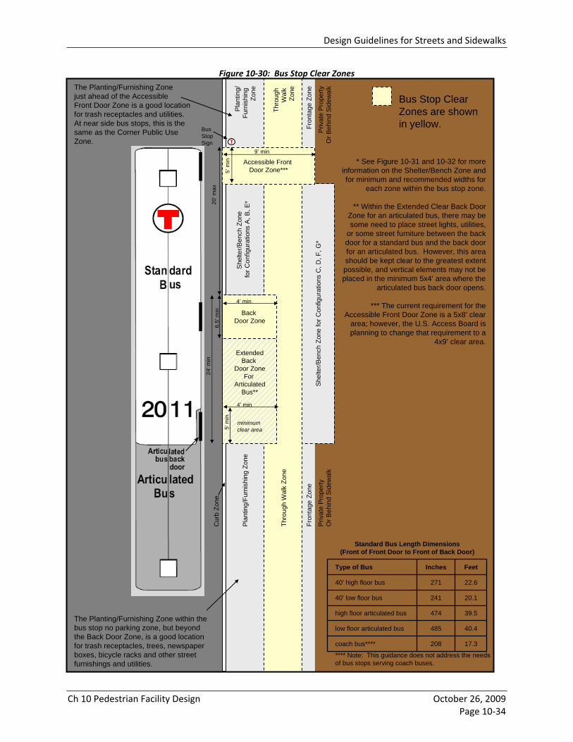
Design Guidelines for Streets and Sidewalks
Ch 10 Pedestrian Facility Design October 26, 2009Page 10 34
Figure 10 30: Bus Stop Clear Zones
She
lter/B
ench
Zon
e fo
r Con
figur
atio
ns C
, D, F
, G*
She
lter/B
ench
Zon
e fo
r Con
figur
atio
ns A
, B, E
*
Accessible Front Door Zone***5’
min
BusStop Sign
9’ min
Back Door Zone
20’m
ax6.
5’m
in
4’ minFr
onta
ge Z
one
ExtendedBack
Door ZoneFor
ArticulatedBus**
minimum clear area
24’m
in
T
Bus Stop Clear Zones are shown in yellow.
The Planting/Furnishing Zonejust ahead of the AccessibleFront Door Zone is a good location for trash receptacles and utilities. At near side bus stops, this is thesame as the Corner Public Use Zone.
The Planting/Furnishing Zone within the bus stop no parking zone, but beyond the Back Door Zone, is a good location for trash receptacles, trees, newspaper boxes, bicycle racks and other street furnishings and utilities.
5’m
in
4’ min
Thro
ugh
Wal
k Zo
ne
Priv
ate
Pro
perty
O
r Beh
ind
Side
wal
k
Plan
ting/
Furn
ishi
ng Z
one
Fron
tage
Zon
e
Thro
ugh
Wal
k Zo
ne
Priv
ate
Pro
perty
Or B
ehin
d Si
dew
alk
Plan
ting/
Furn
ishi
ng
Zone
* See Figure 10-31 and 10-32 for more information on the Shelter/Bench Zone and for minimum and recommended widths for
each zone within the bus stop zone.
** Within the Extended Clear Back Door Zone for an articulated bus, there may be some need to place street lights, utilities,
or some street furniture between the back door for a standard bus and the back door for an articulated bus. However, this area should be kept clear to the greatest extent possible, and vertical elements may not be placed in the minimum 5x4’ area where the
articulated bus back door opens.
*** The current requirement for the Accessible Front Door Zone is a 5x8’ clear
area; however, the U.S. Access Board is planning to change that requirement to a
4x9’ clear area.
Cur
b Zo
ne
17.3208coach bus****
40.4485low floor articulated bus
39.5474high floor articulated bus
20.124140' low floor bus
22.627140' high floor bus
FeetInchesType of Bus
Standard Bus Length Dimensions(Front of Front Door to Front of Back Door)
**** Note: This guidance does not address the needsof bus stops serving coach buses.
Design Guidelines for Streets and Sidewalks
Ch 10 Pedestrian Facility Design October 26, 2009Page 10 34
Figure 10 30: Bus Stop Clear Zones

Design Guidelines for Streets and Sidewalks
Ch 10 Pedestrian Facility Design October 26, 2009 Page 10‐35
10.4.2.3 Back Door Zone
All bus stops should have a clear Back Door Zone to provide access to and from the back door of the bus. It may overlap with the Through Walk Zone. It should be located a maximum of 20’ back from the front of the Accessible Front Door Zone. The length of the Back Door Zone depends upon transit operations and vehicle design: (a) 6.5’ for standard 40’ buses (assuming both high floor and low floor vehicles), (b) 24’ for both standard 40’ buses and 60’ articulated buses (assuming both high floor and low floor vehicles), or (c) 40’ or longer to service front door of second 40’ bus, as illustrated in Figure 10‐30. The Back Door Zone should be a minimum of 4’ deep from the face of curb, and it must connect to the Through Walk Zone via a minimum 4’ wide clear walking path. It should be constructed of a firm, walkable surface, free of tripping hazards. In residential areas, turf grass may be an acceptable walking surface.
If the Clear Back Door Zone is extended for an articulated bus, there may be some need to place street lights, utilities, or some street furniture between the back door for a standard bus and the back door for an articulated bus. However, this area should be kept clear to the greatest extent possible, and vertical elements should not be placed in the area adjacent to where the articulated bus back door opens.
10.4.3 Shelter / Bench Zone There are two basic locations for the placement of bus shelters and bus benches, as shown in Figure 10‐30: within the Planting/Furnishing Zone adjacent between the curb and the sidewalk or in the Frontage Zone/private property area at the back of sidewalk. Within these two basic locations, there are several options for placement of shelters and benches, as described below.
10.4.3.1 Bus Shelters
At bus stops where passenger volumes warrant a shelter, the shelter must be placed outside of the clear zones identified in section 10.4.2. All bus shelters must have a minimum 36x48” clear zone within the shelter and a recommended 5’ and minimum 4’ wide accessible walking route from the bus shelter entrance to the Through Walk Zone and from the bus shelter entrance to the Accessible Front Door Zone.
Where a shelter is warranted, a standard shelter (typically 5x13’) should be used wherever possible. A narrow shelter (typically 2.5 x 13’) may be used where a standard shelter is not feasible; however, a standard shelter is preferred for passenger comfort. Because shelters need to provide a 30x48” clear wheelchair space, the functional minimum width for a narrow shelter is considered to be 4’, although only 2.5’ is a permanent fixture (for typical 2.5’ wide narrow shelters).
Bus shelters must be designed to provide clear visibility between the street and transit passengers inside the shelter for both personal security and for transit operations purposes. On shelters with advertising panels, the ad panels should not be placed to obscure the visibility of waiting transit passengers from the street.
In general, shelters should have closed back walls to provide shelter from wind and rain. Extra long shelters that serve very high passenger volumes may need to have limited open back walls to provide sufficient access between the Through Walk Zone and the Back Door Zone.
There are 4 placement options for bus shelters as shown in Figure 10‐31:
• Configuration A: Street‐Facing Shelter in the Furnishing Zone • Configuration B: Sidewalk‐Facing Shelter in the Furnishing Zone • Configuration C: Shelter behind Sidewalk or on Private Property • Configuration D: Shelter in Frontage Zone
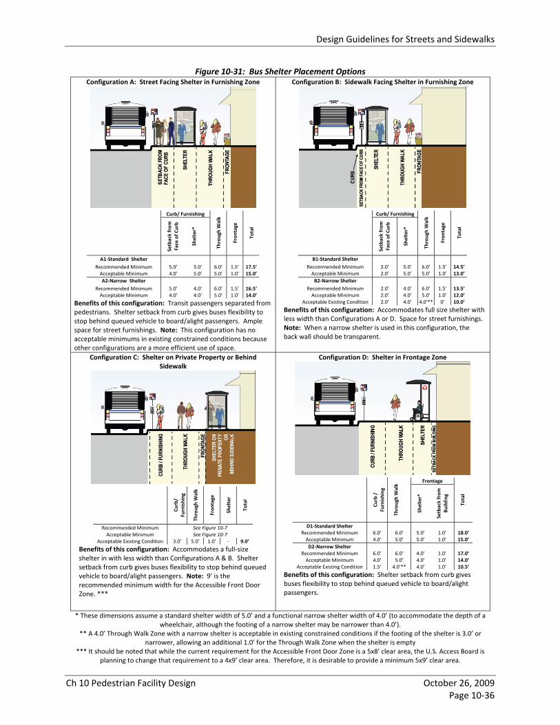
Design Guidelines for Streets and Sidewalks
Ch 10 Pedestrian Facility Design October 26, 2009 Page 10‐36
Figure 10‐31: Bus Shelter Placement Options Configuration A: Street Facing Shelter in Furnishing Zone
Curb/ Furnishing
Setback from
Face of C
urb
Shelter*
Through Walk
Fron
tage
Total
A1‐Standard Shelter Recommended Minimum 5.0’ 5.0’ 6.0’ 1.5’ 17.5’Acceptable Minimum 4.0’ 5.0’ 5.0’ 1.0’ 15.0’A2‐Narrow Shelter
Recommended Minimum 5.0’ 4.0’ 6.0’ 1.5’ 16.5’Acceptable Minimum 4.0’ 4.0’ 5.0’ 1.0’ 14.0’
Benefits of this configuration: Transit passengers separated from pedestrians. Shelter setback from curb gives buses flexibility to stop behind queued vehicle to board/alight passengers. Ample space for street furnishings. Note: This configuration has no acceptable minimums in existing constrained conditions because other configurations are a more efficient use of space.
Configuration B: Sidewalk Facing Shelter in Furnishing Zone
Curb/ Furnishing
Setback from
Face of C
urb
Shelter*
Through Walk
Fron
tage
Total
B1‐Standard Shelter Recommended Minimum 2.0’ 5.0’ 6.0’ 1.5’ 14.5’Acceptable Minimum 2.0’ 5.0’ 5.0’ 1.0’ 13.0’B2‐Narrow Shelter
Recommended Minimum 2.0’ 4.0’ 6.0’ 1.5’ 13.5’Acceptable Minimum 2.0’ 4.0’ 5.0’ 1.0’ 12.0’
Acceptable Existing Condition 2.0’ 4.0’ 4.0’** 0’ 10.0’
Benefits of this configuration: Accommodates full size shelter with less width than Configurations A or D. Space for street furnishings. Note: When a narrow shelter is used in this configuration, the back wall should be transparent.
Configuration C: Shelter on Private Property or Behind Sidewalk
Curb/
Furnishing
Through Walk
Fron
tage
Shelter
Total
Recommended Minimum See Figure 10‐7 Acceptable Minimum See Figure 10‐7
Acceptable Existing Condition 3.0’ 5.0’ 1.0’ ‐ 9.0’
Benefits of this configuration: Accommodates a full‐size shelter in with less width than Configurations A & B. Shelter setback from curb gives buses flexibility to stop behind queued vehicle to board/alight passengers. Note: 9’ is the recommended minimum width for the Accessible Front Door Zone. ***
Configuration D: Shelter in Frontage Zone
Frontage
Curb /
Furnishing
Through Walk
Shelter*
Setback from
Bu
ilding
Total
D1‐Standard Shelter Recommended Minimum 6.0’ 6.0’ 5.0’ 1.0’ 18.0’ Acceptable Minimum 4.0’ 5.0’ 5.0’ 1.0’ 15.0’ D2‐Narrow Shelter
Recommended Minimum 6.0’ 6.0’ 4.0’ 1.0’ 17.0’ Acceptable Minimum 4.0’ 5.0’ 4.0’ 1.0’ 14.0’
Acceptable Existing Condition 1.5’ 4.0’** 4.0’ 1.0’ 10.5’
Benefits of this configuration: Shelter setback from curb gives buses flexibility to stop behind queued vehicle to board/alight passengers.
* These dimensions assume a standard shelter width of 5.0’ and a functional narrow shelter width of 4.0’ (to accommodate the depth of a wheelchair, although the footing of a narrow shelter may be narrower than 4.0’).
** A 4.0’ Through Walk Zone with a narrow shelter is acceptable in existing constrained conditions if the footing of the shelter is 3.0’ or narrower, allowing an additional 1.0’ for the Through Walk Zone when the shelter is empty
*** It should be noted that while the current requirement for the Accessible Front Door Zone is a 5x8’ clear area, the U.S. Access Board is planning to change that requirement to a 4x9’ clear area. Therefore, it is desirable to provide a minimum 5x9’ clear area.
Design Guidelines for Streets and Sidewalks
Ch 10 Pedestrian Facility Design October 26, 2009 Page 10‐37
10.4.3.2 Benches
Where a bench is used at a transit stop, the bench must be placed outside of the clear zones identified in section 10.4.2. A minimum 36x48” clear zone must be provided on at least one side of the bench for a wheelchair user to sit. Benches should not be used in addition to bus shelters unless transit passenger volumes warrant additional seating, as unneeded benches can block the Back Door Zone and clutter the bus stop. Benches with advertising panels must be designed and placed at the bus stop to serve waiting transit passengers, not simply to provide a surface for advertising.
There are 3 basic placement options for benches, as shown in Figure 10‐32:
• Configuration E: Street‐Facing Bench in the Furnishing Zone
• Configuration F: Bench in Frontage Zone
• Configuration G: Bench behind Sidewalk or on Private Property
10.4.4 Other Street Furniture and Utilities
10.4.4.1 Trash Receptacles
Trash receptacles are an important component of a bus stop because they serve waiting transit passengers and help to keep the bus stop clean. Trash receptacles must be placed outside of the clear zones identified in section 10.4.2. The ideal location for trash receptacles is in the Corner Public Use Zone at near‐side bus stops or in the Planting/Furnishing Zone within the bus stop no parking zone, but beyond the Back Door Zone, as shown in Figure 10‐30. Trash receptacles may also be placed in the shelter/bench zone shown in Figure 10‐30, provided they do not block access to the shelter or bench, do not block advertising panels on shelters, and are in a location where they may be serviced. Many trash receptacles in Minneapolis are serviced automatically by garbage trucks that lift them from the sidewalk, remove the trash, and place them back on the sidewalk; these receptacles may require more sidewalk space than manually‐serviced receptacles. Trash receptacles may be placed in the Frontage Zone if they are manually‐serviced and do not block the Through Walk Zone.
10.4.4.2 Street Lights and Utilities
Street lights, utility boxes, manholes and other public and private utilities and infrastructure must be placed outside of the clear zones identified in section 10.4.2 and in a location that does not interfere with the placement of bus shelters or benches within the Shelter/Bench zone. See also section 10.2.5.
10.4.4.3 Other Street Furniture
Bus stops should have adequate space for trees, newspaper boxes, bicycle racks, and other street furnishings. These elements must be placed outside of the clear zones identified in section 10.4.2. The ideal location for these furnishings is in Planting/Furnishing Zone within the bus stop no parking zone, but beyond the Back Door Zone. Furnishings may also be located to a limited extent in the Frontage Zone, as shown in Figure 10‐30.

Design Guidelines for Streets and Sidewalks
Ch 10 Pedestrian Facility Design October 26, 2009 Page 10‐38
Figure 10‐32: Bus Bench Placement Options Configuration E: Street‐Facing Bench in Furnishing Zone
Curb/ Furnishing
Setback from
Face of C
urb
Bench*
Through Walk
Fron
tage
Total
Recommended Minimum 5.0’ 2.5’ 6.0’ 1.5’ 15.0’Acceptable Minimum 4.0’ 2.5’ 5.0’ 1.0’ 12.5’
Acceptable Existing Condition with Protected Curb Lane *
2.5’ 2.5’ 5.0’ 1.0’ 11.0’
Note: If the curb traffic lane at the bus stop is a parking lane or bike lane, the setback from face of curb may be narrowed to 2.5’ in existing constrained conditions if reconstruction is not possible.
Configuration F: Bench in Frontage Zone
Frontage
Curb /
Furnishing
Through Walk
Bench*
Setback from
Bu
ilding
Total
Recommended Minimum 6.0’ 7.0’ 2.5’ 1.0’ 16.5’ Acceptable Minimum 4.0’ 6.0’ 2.5’ 1.0’ 13.5’
Acceptable Existing Condition 1.5’ 5.0’ 2.5’ 1.0’ 10.0’
Note: These Through Walk Zone dimensions assume a seated person on the bench will encroach 1.0’ into the Through Walk Zone.
Configuration G: Bench on Private Property or Behind Sidewalk
Curb/
Furnishing
Through Walk
Fron
tage
Bench
Total
Recommended Minimum See Figure 10‐7 Acceptable Minimum See Figure 10‐7
Acceptable Existing Condition 3.0’ 5.0’ 1.0’ ‐ 9.0’
Note: 9 feet is the minimum recommended width required for the Accessible Front Door Zone.**
* Note: These dimensions assume a standard bench depth of 2.5’. ** It should be noted that while the current requirement for the Accessible Front Door Zone is a 5x8’ clear area, the U.S. Access Board is
planning to change that requirement to a 4x9’ clear area. Therefore, it is desirable to provide a minimum 5x9’ clear area.

Design Guidelines for Streets and Sidewalks
Ch 10 Pedestrian Facility Design October 26, 2009 Page 10‐39
10.4.5 Solutions for Existing Constrained Conditions There are existing bus stops in Minneapolis that do not meet these bus stop design guidelines. Examples include bus stops where the shelter blocks the back door of the bus, or a full size shelter is placed in the Through Walk Zone, or the Accessible Front Door Zone is provided through the inside of the shelter without a back panel.
When there are opportunities to reconstruct these bus stops, such as with street reconstruction projects or major redevelopment opportunities, the recommended widths and placement of elements in these bus stop design guidelines should be followed. When it is not possible to meet all of the recommendations in these guidelines because of the location of utilities, street lights, driveways, or other constraints, the design of bus stops should meet the following criteria (in order of priority):
1. Provide an Accessible Front Door Zone and accessible Through Walk Zone as described in sections 10.4.2.1 and 10.4.2.2.
2. Provide a clear Back Door Zone as described in section 10.4.2.3. 3. Provide seating and/or shelter for waiting transit passengers, as well as space for a trash
receptacle, as passenger volumes warrant. 4. Accommodate expected levels of transit passengers and expected levels of pedestrian activity
relative to the physical space provided for each. 5. Integrate trees and other street furniture into the right‐of‐way or adjacent properties, as
feasible.

Design Guidelines for Streets and Sidewalks
Ch 10 Pedestrian Facility Design October 26, 2009 Page 10‐40
10.5 STREET CROSSINGS Pedestrians have a right to safe, accessible and convenient street crossings. Street crossings that are not designed with pedestrian needs in mind often result in unsafe pedestrian or driver behavior and discourage people from walking.
10.5.1 Legal Crosswalk Definition Whether marked or unmarked, legal crosswalks exist at all legs of all intersections where sidewalks normally exist, including T‐intersections, except where closed by ordinance and appropriately signed. Legal crosswalks also exist at marked midblock crossings. Minnesota state statute defines a legal crosswalk as:
(1) that portion of a roadway ordinarily included with the prolongation or connection of the lateral lines of sidewalks at intersections; (2) any portion of a roadway distinctly indicated for pedestrian crossing by lines or other markings on the surface. 6
At legal crosswalks, motorists are required to stop for pedestrians who have entered the crosswalk. Pedestrians are also permitted to cross the street between intersections, provided they yield right of way to vehicles and they do not cross between adjacent intersections with traffic signals.7
10.5.2 Elements of Safe, Accessible and Convenient Crossings Good pedestrian street crossing design is characterized by:
• Appropriate frequency of crossing opportunities.
• Minimal exposure to vehicles.
• Minimal out of direction travel.
• Minimal delay to pedestrians waiting to cross the street.
• Sufficient signal time and traffic gaps for pedestrians to cross the street.
• Good visibility between drivers and pedestrians (see section 10.3.1.2).
• Clear driver expectations of where and when pedestrians will cross the street.
• Clear pedestrian expectations of where and when it is safe to cross the street
10.5.2.1 Frequency of Crossing Opportunities
Pedestrians should have safe, accessible and convenient crossing opportunities at reasonable distances. Pedestrians will cross the street where it is convenient and generally will not travel out of direction. What constitutes a reasonable distance between crossing opportunities depends on the context of land uses and pedestrian activity along a street. However, in general, pedestrian street crossing opportunities should at approximately the same spacing as the street grid in the surrounding neighborhood.
To ensure that there are safe crossing opportunities at reasonable distances, some crosswalks will warrant pavement markings and/or other treatments (see section 10.5.3), and midblock crossings may be appropriate in some situations (see section 10.5.8.1).
6 Minnesota State Statutes, Chapter 169.01. 7 Minnesota State Statutes, Chapter 169.21.

Design Guidelines for Streets and Sidewalks
Ch 10 Pedestrian Facility Design October 26, 2009 Page 10‐41
10.5.2.2 Pedestrian Delay
Minimizing pedestrian delay in crossing the street increases pedestrian convenience and reduces the likelihood that pedestrians will cross the street in an unsafe manner. Pedestrian delay may be minimized by maintaining short signal cycles at signalized intersections (see section 10.5.5.1) and by ensuring that pedestrians have sufficient frequency and length of gaps in traffic at uncontrolled intersections.
10.5.2.3 Crossing Distance
Short street crossings improve pedestrian safety and convenience. Pedestrian crossing distance should be minimized to the greatest extent possible. AASHTO states:
Short crosswalks help pedestrians cross streets. Excessive crossing distances increase the pedestrian exposure time, increase the potential of vehicle‐pedestrian conflict, and add to vehicle delay. Pedestrian comfort and safety when crossing wide intersections is an essential component of pedestrian facility design. At signalized intersections, reducing the distance pedestrians need to cross an intersection can usually improve the signal timing of the intersection. Where the pedestrian crossing time is the controlling factor, reducing the distance needed for a pedestrian to cross a main street permits the green time for the major street traffic to be increased proportionally. Thus, under certain conditions, reducing the arterial street throat width on an intersection approach may actually increase the capacity of the street.8
Short crossing distances may be achieved through:
• curb extensions (see section 10.3.5)
• median refuge islands (see section 10.5.6)
• realignment of crosswalk at offset or diagonal intersections
• vehicle and parking lane widths (see section 5.3)
• number of vehicle lanes (see section 2.2.10.2)
10.5.2.4 Visibility
Pedestrians need to be visible to vehicle drivers approaching within the roadway. At the same time, pedestrians need to be able to see those same vehicles. With typical intersections that include parking along the roadway, pedestrians standing on the curb are often obscured from a vehicle driver’s view. See section 10.3.1.2 Visibility at Corners for more information.
10.5.2.5 Managing Vehicle Speeds
Motor vehicle speeds have a huge impact on pedestrian safety, such that the likelihood of serious injury or death rises significantly with each speed increment, as shown in Figure 10‐33. Faster vehicle speeds make it much more difficult for pedestrians to judge safe gaps in traffic for crossing. Thus, it is paramount that streets should be designed and operated with speed management in mind. Most streets in Minneapolis have posted speed of 30 mph. Refer to section 4.4 for more information on roadway design and operating speeds.
8 Source: Guide for the Planning, Design, and Operation of Pedestrian Facilities, AASHTO

Design Guidelines for Streets and Sidewalks
Ch 10 Pedestrian Facility Design October 26, 2009 Page 10‐42
Figure 10‐33: Pedestrians’ Chance of Death if Hit by Motor Vehicle
85%
45%
15%0%
25%
50%
75%
100%
20 mph 30 mph 40 mph
Vehicle Speed
Pede
strians' Chance of Death
Source: Killing Speed and Saving Lives, UK Department of Transportation.
10.5.3 Crosswalk Markings
10.5.3.1 Purpose
The purpose of crosswalk markings is to:
• Indicate to pedestrians preferred crossing locations.
• Alert road users of likely pedestrian crossing locations.
• Legally designate midblock crosswalks.
In addition, crosswalks markings also help to:
• Prevent vehicular traffic from blocking the pedestrian path when stopping for a stop sign or red light.
• Align pedestrians to cross in the crosswalk, not the parallel traffic lane.
• Remind turning drivers of potential conflicts with pedestrians.
10.5.3.2 Location
Crosswalk markings are a basic tool for directing pedestrians safely across the street and warning drivers of pedestrian crossings. It is not necessary or practical to mark all legal crosswalks. Many crosswalks, particularly on local residential streets, are safe without crosswalk markings. Crosswalk markings need to be maintained, and it is important to balance the maintenance costs with the benefits that crosswalk markings provide.
The decision about where to mark crosswalks should be based upon sound engineering judgment. In general, marked crosswalks and other safety treatments should be prioritized at locations where pedestrians are vulnerable to conflicts with vehicles due to:
• High pedestrian and vehicular volumes, such as in business districts, major bus stops, universities
• Vulnerable populations such as children, senior citizens, people with disabilities, or hospital patients
• Difficult roadway conditions for pedestrians to cross, such as wide crossing distances, high traffic speeds, complex intersection geometry

Design Guidelines for Streets and Sidewalks
Ch 10 Pedestrian Facility Design October 26, 2009 Page 10‐43
Marked crosswalks are one form of pedestrian safety enhancement. In general, they may be safely used alone at traffic signal and stop sign controlled intersections. However, in many cases, at uncontrolled intersections, crosswalk markings should be used in combination with other treatments because they may not alone provide a safe crossing. 9 In these situations, additional treatments (e.g., curb extensions, raised crossing islands, traffic signals, roadway narrowing, enhanced overhead lighting, traffic calming measures) should be employed to create a safe crossing.
Minneapolis’ current policy is to always mark crosswalks at the following types of locations:
• Signalized intersections
• Designated midblock crosswalks
• School patrolled crossings
10.5.3.3 Design
Crosswalk markings must be visible to both the pedestrian and the driver. In general, pedestrians can see crosswalk markings much more easily than drivers because they are closer to the intersection and approaching it at a different angle. For drivers, longitudinal markings are more highly visible than the two transverse lines (see Figure 10‐34). Transverse and longitudinal styles are typically used in Minneapolis.
• Standard (Transverse) Crosswalk Markings ‐ A standard crosswalk consists of two transverse (parallel) lines, each 6 inches in width and striped 15 feet apart in downtown and activity centers and 10 feet in other locations. To improve visibility of transverse markings, a 12‐inch line width can be used instead of a 6‐inch line width.
• High‐visibility (Longitudinal) Crosswalk Markings ‐ A high‐visibility crosswalk consists of longitudinal lines striped parallel to the direction of traffic. The longitudinal lines should be between 12 and 24 inches in width and spaced 12 to 60 inches apart. The markings may be striped to avoid the wheel paths of vehicles, reducing maintenance needs (see Figure 10‐35). The longitudinal lines may be used alone or in addition to transverse lines, thus creating a ladder‐style crossing.
At marked crosswalks, curb ramps and other sloped areas should be wholly contained within the crosswalk makings, excluding any flared sides. The crosswalk lines should extend the full length of the crossing.
Longitudinal markings should be used where there is a need to alert drivers to unexpected pedestrian crossings, to alert drivers to particularly vulnerable pedestrian users, or to channelize pedestrians to a preferred crossing location. They may be appropriate at the following locations:
9 A 1995 study by the UNC Highway Safety Research Center on the safety of marked crosswalks at uncontrolled intersections found that crosswalks markings should not be used alone without additional treatments at the following types of uncontrolled intersections:
Where the speed limit exceeds 40 miles per hour.
On a roadway with four or more lanes without a raised median or crossing island that has (or will soon have) an ADT of 12,000 or greater.
On a roadway with four or more lanes with a raised median or crossing island that has (or soon will have) an ADT of 15,000 or greater.

Design Guidelines for Streets and Sidewalks
Ch 10 Pedestrian Facility Design October 26, 2009 Page 10‐44
• Mid‐block crosswalks, including mid‐block trail crossings
• Uncontrolled intersections where crosswalk markings are needed
• Selected school patrolled crossings where there is a need to provide additional driver awareness of pedestrians or to channelize pedestrians to a particular crossing leg
• Intersections with complex geometry or unusual signal operations where there may be a need to direct pedestrians to preferred crossing locations or alert drivers of significant vehicular‐pedestrian conflicts
• Marked crosswalks on higher speed roadways (40 mph or greater)
Longitudinal markings require more pavement marking material than transverse markings, and as a result have higher installation costs. Staggered spacing on longitudinal markings to avoid vehicle wheel paths can, however, reduce maintenance costs (see Figure 10‐35).
Figure 10‐34: Visibility of Lateral vs. Longitudinal Crosswalk Markings
Source: Guide for the Planning, Design, and Operation of Pedestrian Facilities, AASHTO
Figure 10‐35: Staggered Spacing of Longitudinal Crosswalk Markings
10.5.3.4 Crosswalk Materials
Options for crosswalk marking materials include latex paint, epoxy, inlay tape and thermoplastic. Although initially more costly than paint, both inlay tape and thermoplastic provide better performance over the life of the crosswalk markings. Inlay tape is recommended for new and resurfaced pavement, while thermoplastic may be a better option on rougher pavement surfaces. Both inlay tape and

Design Guidelines for Streets and Sidewalks
Ch 10 Pedestrian Facility Design October 26, 2009 Page 10‐45
thermoplastic are more visible and less slippery than paint when wet. Most crosswalks in Minneapolis are currently marked with latex paint once every other year; reflective roadway tape and thermoplastic materials have been used in selective locations.
10.5.3.5 Textured and Colored Pavement Crosswalks
Colored and textured crosswalk design treatments are sometimes used to enhance the streetscape. While textured and color pavement treatments may improve the quality of the urban design and can help to create an environment that attracts more pedestrians, it does not typically improve pedestrian safety. Often textured and colored pavement is not as visible to drivers as to pedestrians. When colored pavement is used, crosswalks should be supplemented with white lines to establish the legal crosswalk and increase visibility. Another way to increase visibility is to imbed a crosswalk within paving of a contrasting color.
In addition, care should be taken to ensure that the material used in these crosswalks is smooth, non‐slip, and viable. Some textured crosswalks can be uncomfortable to cross in wheelchairs, painful to pedestrians with sensitive (such as spinal) injuries, and frustrating to those using canes, high heels, rolling luggage, or grocery carts. Avoid using a paving system that may shift and/or settle or that includes a high degree of jarring or vibration on wheelchair wheels.
See also section 10.2.7.1 on sidewalk surface design.
10.5.3.6 Advance Stop Bar Markings and Locations
Multi‐lane roadways present a unique threat to pedestrians crossing, as vehicles in one lane can block the visibility of a motorist traveling in the adjacent lane. The law dictates that vehicles must stop to pedestrians in a crosswalk. Placing a stop bar 20 to 50 feet ahead of the crosswalk improves visibility for both the motorist and the pedestrian. Striping a line before the crosswalk also gives an extra indication to the driver that it is their responsibility to stop. This measure is illustrated in Figure 10‐36. This application is appropriate at any crossing on multilane roadways or designated midblock crosswalks.
Figure 10‐36: Advanced Stop Bar
10.5.4 Signs Pedestrian crossing signs alert drivers that there are pedestrians in the area and remind them that automobiles must stop for pedestrians in the crosswalk. Pedestrian crossing signs are especially

Design Guidelines for Streets and Sidewalks
Ch 10 Pedestrian Facility Design October 26, 2009 Page 10‐46
important at school crossings, mid‐block crossings, and unsignalized locations with high pedestrian volume.
10.5.4.1 Standard Signs
Pedestrian signs should be placed according to MMUTCD standards. The pedestrian crossing standard, with an arrow pointing down to the crosswalk, is generally easily understood by the public (see Figure 10‐37). Primary location for pedestrian crossing signs should be in advance of crosswalk and the supplemental location should be at the crosswalk. Pedestrian signs in school zones should follow the City of Minneapolis School Pedestrian Safety Toolbox.
Figure 10‐37: MMUTCD Pedestrian crossing sign
10.5.4.2 Supplemental Signs
Supplemental post mounted signs can improve visibility of crosswalks. Overhead signs can be used to draw attention to the presence of a crosswalk and can also be supplemented by flashing beacons. Various design options are available, ranging from static signs to flashing lights that activate when a pedestrian pushes a button at the curb.
Another way to draw attention to a crosswalk and educate the motorist at the same time is to place a paddle board or removable sign directly in the crosswalk, as shown in Figure 10‐38. The sign states the law and draws attention to the crosswalk directly. This tool is often used at downtown activity center locations with many pedestrian generators and near schools. In‐street signs increase rates of vehicles yielding to pedestrians, especially on slow‐speed streets. They should not be used on high‐speed, multi‐lane roadways.

Design Guidelines for Streets and Sidewalks
Ch 10 Pedestrian Facility Design October 26, 2009 Page 10‐47
Figure 10‐38: Removable In‐Street Pedestrian Crossing Sign
10.5.5 Signals There are approximately 800 traffic signals in Minneapolis, nearly all of which have pedestrian signal heads. Pedestrian signals direct pedestrian traffic by communicating when pedestrians are supposed to cross the street. Pedestrian signal heads should be installed at all signalized intersections where there are pedestrian crossings.
10.5.5.1 Cycle Lengths / Pedestrian Delay
Longer signal cycles (simply, the overall time a motorist has to wait for the next ‘green light’) create more delay for pedestrians waiting to cross the street and can lead to impatient pedestrians crossing against the signal. Therefore, signal cycles and pedestrian delay in high pedestrian areas should be kept to the minimum needed to accommodate pedestrian crossing intervals and vehicular demand.
10.5.5.2 Crossing Interval / Crossing Time
The proposed 2009 MUTCD will require that signal timing for the pedestrian clearance time be based on a pedestrian crossing speed of 3.5 feet per second, and the total Walk plus Flashing Don’t Walk time be based on 3.0 feet per second. Most signals in Minneapolis currently meet this standard, and it should be used in all future signal timings.
10.5.5.3 Countdown Timers
The countdown timer (see Figure 10‐39) shows the number of seconds remaining until the steady “upraised hand” signal is shown. Countdown signals benefit pedestrians by allowing them to anticipate when the traffic light will change. Pedestrians can use this information to decide if they have enough time to cross the street and judge whether or not to enter the intersection.
Countdown timers are standard in all new signal installations in Minneapolis (as of 2008), and the proposed 2009 MUTCD will require that all signalized intersections use countdown signals where pedestrian crosswalks exist.

Design Guidelines for Streets and Sidewalks
Ch 10 Pedestrian Facility Design October 26, 2009 Page 10‐48
Figure 10‐39: Pedestrian Countdown Timer
10.5.5.4 Pedestrian Detection / Push Buttons
Pedestrian traffic signals operate in three modes:
• Pre‐timed signals ‐ Pre‐timed signals do not require pedestrian push buttons because the pedestrians are given a walk signal for every legal crossing every cycle. This type of signal is common in downtown. Approximately two‐thirds of Minneapolis signals operate in this mode.
• Semi‐actuated signals ‐ These signals require pedestrian activation for crossing the major street and no pedestrian activation for crossing the minor street. Both the traffic Green signal and "WALK" signal phases are ON for the major street when no other movement requests are detected. The pedestrian is required to push the button to activate the "WALK" signal to cross the major street. These signals tend to be at intersections where streets are unequal in volume and are primarily done as an effort to maximize the efficiency of vehicular movements. Approximately one‐third of Minneapolis signals operate in this mode.
• Fully‐actuated signals – Fully‐actuated signals have pedestrian activation for all legal crossings. The traffic green signal phase is on for the major street when no other movement requests are detected. The pedestrian is required to push the button to activate the "WALK" signal to cross all streets. Less than two percent of Minneapolis signals operate in this mode.
With any actuated signal, pedestrians must be detected through pushing a button. In most actuated situations, the WALK signal occurs with the parallel green signal at the next signal cycle, resulting in a delay for pedestrians of up to one minute after pushing the button. This can cause frustration for pedestrians who don’t know if the push button is working and if the signal system has received the pedestrian’s call. When actuated signals are used, it is essential that push buttons be convenient to use and well‐maintained. They should clearly display the direction of crossing, have a large button, and be placed in accessible location (see section 10.3.4 and Figure 10‐40). It is also desirable that push buttons have a visual indication that the button has been pushed.
There are also a variety of new technologies for detecting pedestrians through activating infrared, digital cameras or other types of detectors.

Design Guidelines for Streets and Sidewalks
Ch 10 Pedestrian Facility Design October 26, 2009 Page 10‐49
Figure 10‐40: Pedestrian Signal Call Button
10.5.5.5 Accessible Pedestrian Signals
Accessible pedestrian signals (APS) provide the information in the WALK and DON’T WALK visual indications in standard pedestrian signals to blind and low vision pedestrians through audible and vibro‐tactile indications of the WALK interval. The audible indication of the WALK interval is provided by tone or speech message. Pedestrian signal devices provide tactile and visual signs on the face of the device or its housing or mounting to indicate crosswalk direction for the crosswalk served by that pedestrian signal. Signs include a tactile arrow aligned parallel to the crosswalk direction. APS may also provide street name information in audible format.
Installation of APS should follow the City’s APS evaluation criteria presented to City Council in the draft APS transition plan (2009), under which all traffic signals will be evaluated and prioritized for APS installation over a 10 year period.
See also Section 10.3.4 on locating pedestrian signal call buttons.
10.5.5.6 Flashing Warning Beacons and Half Signals
Flashing warning lights can give a pedestrian crosswalk more visibility to motorists. These are located adjacent to, or in advance of, the crosswalk and accompany pedestrian crossing signs. They are generally push‐button activated. These should be used where pedestrian traffic is intermittent and no other traffic control is present.
Half signals are located at street‐arterial intersections. They are pedestrian‐actuated signals that stop arterial traffic only, leaving the lower volume street unsignalized. The signal is only activated when pedestrians are present.
Other advanced signal types, such as HAWK signals10, are in the MUTCD ‘experimental’ category and may be available for installation on a case‐by‐case basis.
10 The pedestrian beacon, or HAWK signal, is currently in experimental use by the FHWA and is proposed for approval in the 2009 MUTCD. These signals are pedestrian actuated and are appropriate at otherwise unsignalized crossings. The HAWK signal has three signal lights, two red lights side by side over a red light. When not activated, the lights are not illuminated. When a pedestrian activates the signal via a push button, the signal begins flashing yellow and then solid yellow, advising drivers to prepare to stop. The signal switches to a solid red for drivers and shows the pedestrian a “Walk” indication. Finally, the red lights flash alternately indicating that motorists may proceed when safe, after coming to a full stop. Meanwhile the pedestrian is shown a flashing “Don’t Walk” and countdown signal.

Design Guidelines for Streets and Sidewalks
Ch 10 Pedestrian Facility Design October 26, 2009 Page 10‐50
10.5.5.7 Leading Pedestrian Intervals
A ‘Leading Pedestrian Interval’11 displays a two to four second WALK signal in advance of the vehicular Green indication, so that vehicles have an all‐red interval. This interval follows an all‐red clearance phase. This signal phase allows pedestrians to establish a presence in the intersection and reduces vehicle pedestrian conflicts. It can be particularly effective where there are turning vehicle conflicts with pedestrians.
10.5.6 Pedestrian Refuge and Median Islands Adding a pedestrian refuge island or median island in the center of a roadway can provide a safe place for pedestrians to wait for a gap in traffic, where they are removed from vehicles. Pedestrian refuge islands are particularly useful at unsignalized crossings or at signals with wide crossings where a pedestrian has a difficult time making it across the whole intersection during one walk phase Refuge islands create a safer crossing by shortening crossing distances and simplifying the crossing. Refuge islands should not be used to justify a signal timing that does not allow pedestrians to cross in one signal cycle.
10.5.6.1 Center Median Islands
The design of center median islands should account for the following:
• Location ‐ AASHTO recommends that medians should be considered where the crossing distance exceeds 60 feet (roughly 5 lanes), but can be used at intersections with shorter crossing distances with a recognized need.
• Width ‐ 6 feet or wider
• Accessibility ‐ Center medians should be designed in accordance with requirements of the ADA and PROWAG at crossings to ensure that the refuge island does not act as an obstruction to crossing the roadway.
• Alignment ‐ An angled or staggered cut‐through on pedestrian refuge (see Figure 10‐41) benefits pedestrian safety by “steering” pedestrians so they face oncoming traffic as they move across the island. To improve wayfinding for pedestrians with visual impairments, the ends of the cuts should be aligned with the crosswalks (and fitted with a detectable warning strip).
• Snow Clearance – Pedestrian refuge islands require additional snow clearance responsibilities for the City, unlike snow clearance of sidewalks, which is the responsibility of adjacent property owners.
• Other Considerations ‐ At unsignalized and/or mid‐block locations, refuge islands may be supplemented with other treatments such as crosswalk markings, signs, or signals to allow a safer crossing.
It should be noted that planted center medians do not always benefit pedestrians. Planted center medians do not provide a pedestrian refuge at intersections if left turn lanes eliminate the planted center median at intersections, which is a common design. They can take away space from the Planting/Furnishing Zone, which may be more useful to pedestrians in providing space for shade trees along sidewalks, transit shelters, and street furnishings. Planted center medians are also sometimes used to eliminate cross‐street access for traffic calming or access management purposes; in these cases,
11 The City’s current central computer system does not accommodate Leading Pedestrian Interval, but planned system upgrades in 2011‐2012 may accommodate the feature in the future.

Design Guidelines for Streets and Sidewalks
Ch 10 Pedestrian Facility Design October 26, 2009 Page 10‐51
pedestrian access across the center median should be maintained at intersecting streets, as shown in Figure 10‐42.
Figure 10‐41: Angled Median Refuge Island
Source: Guide for the Planning, Design, and Operation of Pedestrian Facilities, AASHTO
Figure 10‐42: Median Refuge Island with Pedestrian Access
Location: Marshall Avenue, St. Paul
10.5.6.2 Channelized Right Turn Lanes
Channelized right turn lanes should not be used in new construction, except where unique street geometry requires them. Where they are required, a well‐designed raised corner island can provide a refuge for pedestrians crossing multiple lanes at a complex intersection (See Chapter 5, Figure 5‐11 Angle of Dedicated Right‐Turn Lane).
If an unsignalized urban right‐turn lane is provided, it should be designed for slow speeds (5‐10 mph), high pedestrian visibility and clear yield‐to‐pedestrian signs and markings. Adding pedestrian refuge

Design Guidelines for Streets and Sidewalks
Ch 10 Pedestrian Facility Design October 26, 2009 Page 10‐52
islands to a problematic intersection is often a beneficial alternative to redesigning an entire intersection.
AASHTO recommends that pedestrian crossings to corner islands meet the following criteria:
• The pedestrian crossings should be at 90 degrees across the turn lane and placed where the motorist can easily see the pedestrian crossing ahead.
• Pedestrians and motorists should be able to easily see each other.
• The design should encourage low‐vehicle‐turning speeds.
Figure 10‐43 shows an example of a well‐designed right slip turn lane with pedestrian refuge islands.
Underused free right‐turn lanes should be removed to provide additional pedestrian space and to reduce both the speed of turning vehicles and pedestrian exposure. Reclaimed space from free right turn lane removal can be developed into space for public plazas or used for street furniture and/or small‐scale plantings.
Figure 10‐43: Proper Design of Channelized Right Turn Lane
10.5.7 Lighting Proper lighting has a beneficial effect on the safety level of the pedestrian. Adequate lighting should be provided at both unsignalized and signalized intersections if pedestrians are present during nighttime hours. Lighting should not only highlight the presence of intersection crosswalks, but also mid‐block crossings.
See Section 7 for further guidance on City’s Lighting Policy.
10.5.8 Unique Types of Crossings
10.5.8.1 Mid‐Block
Mid‐block crossings may be appropriate for unusually long blocks with pedestrian generators, such as schools, stadiums, museums, office buildings, etc.. These types of crossings generally require special design treatment such as marked crosswalks, raised medians, curb extensions, pedestrian signals and signs to indicate to drivers that pedestrians may cross.

Design Guidelines for Streets and Sidewalks
Ch 10 Pedestrian Facility Design October 26, 2009 Page 10‐53
Certain locations such as those with sparse land use, low pedestrian volumes, or poor driver visibility should be avoided as they work against driver expectations and decrease safety for pedestrians.
10.5.8.2 Freeway Ramps
Crossings across freeway ramps can be more dangerous than typical pedestrian crossings. Automobiles exiting from the freeways are traveling at higher speeds and are transitioning from a pedestrian‐free environment. Vehicles entering freeways are accelerating and focused on merge maneuvers. Additionally, pedestrians typically have to walk across multiple lanes. Freeway on‐ramps and off‐ramps in urban areas should be designed as urban intersections where the on‐street design speed dictates turning radii. The AASHTO Guide for the Planning, Design, and Operation of Pedestrian Facilities provides the following guidance on the intended entrance/exit speed, “Design the exits for 20 mph at ramp‐street situations in urban environments” (p.79). Freeway ramps should have clear sight lines.
10.5.8.3 Cul‐de‐Sacs/Diverters/Closed Streets
Cul‐de‐sacs, diverters, and closed streets interrupt the street grid. Crossings at these locations should emphasize maintaining the same pedestrian connectivity and accessibility as a standard intersection.
10.5.8.4 Raised Intersections and Raised Crossings
Raised intersections elevate the entire plane of the intersection and crosswalks to three or four inches above the surrounding streets. These intersections slow traffic and increase pedestrian visibility. Properly designed raised intersections are suitable for buses and trucks but should have warning signs for drivers. Raised intersections are appropriate and effective in school zones, urban intersections, business districts and other areas where pedestrian movements are a priority.
Raised crossings are a similar application, but at a midblock crossing. Raised crossings are used selectively throughout the city. This raised height gives pedestrians higher visibility as they cross the street and also acts as a traffic calming device because cars need to slow down as they approach the change in grade. In Minneapolis, raised crossings are used in limited locations such as along the parkway system, where automobile speeds are below 30 mph and there is steady pedestrian traffic due to the parkway trail system. Raised crossings should not be used on collector or arterial streets, bus routes, or any intersection approach with stop signs or signal control devices to reduce speeds. They can occasionally be used at mid‐block crossings with appropriate warning signage. Drainage should be considered during design due to the crossing extending curb to curb. Modifications to the design, by providing a French drain at the gutter, can facilitate adequate drainage.
Raised intersections and raised crossings are not currently allowed on Minnesota State Aid Streets.
Figure 10‐44: Raised Intersection
Location: Oak Park, Illinois

Design Guidelines for Streets and Sidewalks
Ch 10 Pedestrian Facility Design October 26, 2009 Page 10‐54
10.5.8.5 Roundabouts
Roundabouts are increasingly popular for use in place of signals at relatively busy intersections. The primary purpose of roundabouts is to provide motor vehicles with free‐flowing mobility at reduced speeds through an intersection.
Research suggests that there may be fewer vehicle‐pedestrian conflicts and crashes at properly designed single‐lane roundabout intersections versus typical signalized or unsignalized intersections. However, there is some concern that it is difficult for pedestrians with vision impairments to obtain cues concerning gap availability for crossing near roundabouts, particularly at multi‐lane roundabouts. Currently underway national research should lead to appropriate solutions in the short term.
10.5.8.6 Grade‐Separated Crossings
Grade separated crossings (above via bridge or beneath via underpass) are often located across freeways, parkways, and rail lines, and often represent the only option to cross a significant barrier. These are more expensive than at‐grade crossings due to the cost of the structure and/or excavation. The designer should recognize that they often make pedestrians walk farther, which discourages pedestrians from using them at all. To be well designed and functional, grade‐separated crossings should pay special attention to accessibility, user comfort and personal safety, including preserving good sight lines.
See also sections 10.6.2.2 and 10.6.2.3 on non‐motorized bridges and underpasses.
10.5.8.7 Prohibited Crossings
Prohibited pedestrians crossings are a tool of last resort and should be avoided unless strong safety concern warrants their use.
10.6 OTHER PEDESTRIAN NETWORKS In addition to the sidewalk system, Minneapolis has other important networks that are key to pedestrian circulation, including the Skyway System and the off‐street path system. This section provides the appropriate guidelines for these off‐street pedestrian networks.
10.6.1 Skyway System Minneapolis has an extensive downtown Skyway System that provides convenient access between offices, retail, hotels and parking ramps. It has played a key role in maintaining and enhancing the economic health of downtown Minneapolis. However, it also has had the effect of minimizing street‐level retail and street‐level pedestrian activity. While it provides convenient access for those who use it regularly, it can be confusing and difficult to navigate for those who don’t use them regularly.
City Policy directs continued improvement and limited expansion of the Downtown Skyway System. The guidance in this section is based upon the City’s 2003 Downtown East North Loop Master Plan and the 2007 Access Minneapolis Downtown Transportation Action Plan.
10.6.1.1 Appropriate Locations
The existing Skyway System should be completed and expanded within the core of downtown and to other key high‐intensity uses, such as the new Ballpark, as shown in Figure 10‐45. Limiting Skyway System expansion to this core area facilitates street‐level land uses and pedestrian activity in growing residential neighborhoods, while also ensuring that new skyways will have sufficient use for safety and security.
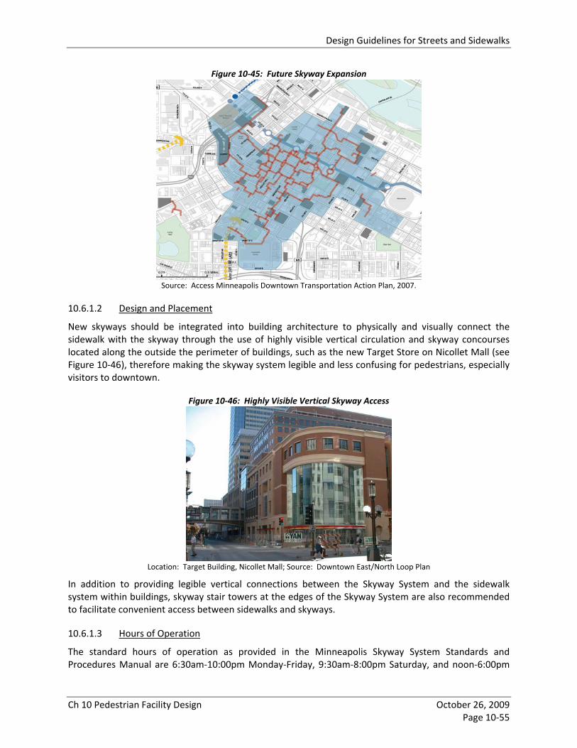
Design Guidelines for Streets and Sidewalks
Ch 10 Pedestrian Facility Design October 26, 2009 Page 10‐55
Figure 10‐45: Future Skyway Expansion
Source: Access Minneapolis Downtown Transportation Action Plan, 2007.
10.6.1.2 Design and Placement
New skyways should be integrated into building architecture to physically and visually connect the sidewalk with the skyway through the use of highly visible vertical circulation and skyway concourses located along the outside the perimeter of buildings, such as the new Target Store on Nicollet Mall (see Figure 10‐46), therefore making the skyway system legible and less confusing for pedestrians, especially visitors to downtown.
Figure 10‐46: Highly Visible Vertical Skyway Access
Location: Target Building, Nicollet Mall; Source: Downtown East/North Loop Plan
In addition to providing legible vertical connections between the Skyway System and the sidewalk system within buildings, skyway stair towers at the edges of the Skyway System are also recommended to facilitate convenient access between sidewalks and skyways.
10.6.1.3 Hours of Operation
The standard hours of operation as provided in the Minneapolis Skyway System Standards and Procedures Manual are 6:30am‐10:00pm Monday‐Friday, 9:30am‐8:00pm Saturday, and noon‐6:00pm

Design Guidelines for Streets and Sidewalks
Ch 10 Pedestrian Facility Design October 26, 2009 Page 10‐56
Sunday. Because the Skyway System is privately owned and has multiple owners, these operating hours are encouraged, but are not mandatory.
10.6.1.4 Wayfinding
The Skyway System has a standard wayfinding signage system, including building signs and system maps. Although voluntary, most building owners have adopted this standard signage, and it is recommended for use in all downtown skyways. The standard wayfinding signage includes signage identifying skyway entries at street level.
10.6.2 Non‐Motorized Trails, Bridges, Underpasses and Stairs Off‐street pedestrian facilities have unique design standards. The same design issues that are addressed above for on‐street facilities will be covered here in the context of trails, pedestrian bridges, underpasses and stairs.
10.6.2.1 Non‐Motorized Trails
Public multi‐use trail design shall follow the Mn/DOT Bikeway Facility Design Manual and AASHTO Guidelines. Major features of that guidance include:
• Width ‐ A minimum width of 10 feet is required for multi‐use bicycle and pedestrian paths. The width for pedestrian‐only walkways should follow the guidance in Section 10.2 for the Through Walk Zone, as well as a clear zone on either side of the walkway.
• Grade – The cross‐slope for trails is the same as for sidewalks: maximum 2%.
• Surface Material ‐ Pathways shall be built to meet Mn/DOT Bikeway Facility Design Manual and ADA standards and should be easily maintained over time.
• Lighting – Multi‐use and pedestrian trails should be adequately lit to provide personal security and safety at street crossings.
10.6.2.2 Non‐Motorized Bridges
Minneapolis currently has two‐types of non‐motorized bridges: freeway/street crossing bridges and creek/water bridges. Though these bridges provide connections, they can be psychological barriers to pedestrians because the spans can be long, which makes pedestrians feel isolated and vulnerable. Bridges should be designed to make pedestrians feel safe and well protected from the elements.
• Width – The minimum width should be the width of approaching trail plus 2 feet or 12 feet, whichever is greater.
• Grade – The approach of bridges should be a maximum 5% grade.
• Surface Material – Non‐slip ‐ typically wood or concrete.
• Lighting – As necessary for user safety. Users should be able to identify other trail users from a distance and the upcoming trail alignment. Lighting should not create sharp differences in brightness, as this works against effective illumination.
10.6.2.3 Non‐Motorized Underpasses
• Width and Vertical Clearance ‐ The minimum width should be the width of approaching trail plus 2 feet or 12 feet, whichever is greater. Wider openings and underpass widths are desired
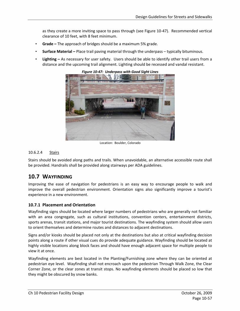
Design Guidelines for Streets and Sidewalks
Ch 10 Pedestrian Facility Design October 26, 2009 Page 10‐57
as they create a more inviting space to pass through (see Figure 10‐47). Recommended vertical clearance of 10 feet, with 8 feet minimum.
• Grade – The approach of bridges should be a maximum 5% grade.
• Surface Material – Place trail paving material through the underpass – typically bituminous.
• Lighting – As necessary for user safety. Users should be able to identify other trail users from a distance and the upcoming trail alignment. Lighting should be recessed and vandal resistant.
Figure 10‐47: Underpass with Good Sight Lines
Location: Boulder, Colorado
10.6.2.4 Stairs
Stairs should be avoided along paths and trails. When unavoidable, an alternative accessible route shall be provided. Handrails shall be provided along stairways per ADA guidelines.
10.7 WAYFINDING Improving the ease of navigation for pedestrians is an easy way to encourage people to walk and improve the overall pedestrian environment. Orientation signs also significantly improve a tourist’s experience in a new environment.
10.7.1 Placement and Orientation Wayfinding signs should be located where larger numbers of pedestrians who are generally not familiar with an area congregate, such as cultural institutions, convention centers, entertainment districts, sports arenas, transit stations, and major tourist destinations. The wayfinding system should allow users to orient themselves and determine routes and distances to adjacent destinations.
Signs and/or kiosks should be placed not only at the destinations but also at critical wayfinding decision points along a route if other visual cues do provide adequate guidance. Wayfinding should be located at highly visible locations along block faces and should have enough adjacent space for multiple people to view it at once.
Wayfinding elements are best located in the Planting/Furnishing zone where they can be oriented at pedestrian eye level. Wayfinding shall not encroach upon the pedestrian Through Walk Zone, the Clear Corner Zone, or the clear zones at transit stops. No wayfinding elements should be placed so low that they might be obscured by snow banks.

Design Guidelines for Streets and Sidewalks
Ch 10 Pedestrian Facility Design October 26, 2009 Page 10‐58
Street signs also provide valuable wayfinding information for pedestrians and should be oriented towards both pedestrians and motorists.
The placement of wayfinding elements should be coordinated with other street furniture.
10.7.2 Wayfinding Design The wayfinding system should be coordinated system of signs, maps and/or kiosks with a distinct visual appearance that will heighten city identity and allow users to quickly and easily find the wayfinding elements. This will help to make wayfinding information more identifiable citywide, decrease overall production costs, and facilitate map updating, reproduction and installation. Graphic design standards including fonts, colors, and pictographs should be standardized for wayfinding elements citywide and should consider legibility for a majority of the population. Wayfinding elements should be resistant to vandalism and designed for ease of maintenance and updating.
10.7.3 Wayfinding Infrastructure Maintenance Over time, wayfinding signage and kiosks will become outdated or damaged and will require ongoing maintenance. Currently, there is no dedicated funding source for maintenance of wayfinding signage in Minneapolis. Responsibility for maintenance funding of wayfinding signage must be established before any wayfinding infrastructure is installed.
10.8 SITE PLANNING While generally not part of the public right‐of‐way, the development of a site can have a significant impact on the pedestrian environment. The City’s Comprehensive Plan policies provide general guidance that supports traditional urban design. This section addresses site design guidance that acknowledges pedestrians and accounts for both their safety and convenience.
10.8.1 Building Facade Building design, whether it is a storefront, an apartment, a light industrial or an office building, has strong influence on the pedestrian environment, especially those that are located on, or are in close proximity to, the street right‐of‐way. Well‐designed buildings should incorporate pedestrian scaled building materials and elements, such as signs and lighting; promote pedestrian activity by adding visual interest to the street; add to a sense of safety through window opacity; and provide clearly defined principal entrances fronting the street. The City of Minneapolis Great Streets Façade Design Guide provides additional guidance on designing and redesigning pedestrian‐friendly storefronts.
10.8.2 Human‐scale Building Massing, Height and Step‐backs The massing of a building can have a significant impact on pedestrian zone aesthetics and comfort (i.e. generation of wind currents, access to light and shadowing effectsand sunlight). Building mass and height in close proximity to the public right‐of‐way should be pedestrian scaled. The use of building step‐backs in upper floors of taller buildings can lessen negative impacts on allow for additional building height and density without adversely impacting the pedestrian environment.
10.8.3 Building Setback Building setbacks can alleviate problems associated with limited right‐of‐way space in constrained conditions by allowing more space for the pedestrian zone. Building setbacks can provide pocket parks along corridors or at corners to allow space for pedestrians to gather and relax.

Design Guidelines for Streets and Sidewalks
Ch 10 Pedestrian Facility Design October 26, 2009 Page 10‐59
10.8.4 Building Entrance Location When designing larger buildings, where the building façade occupies a majority of the block length, consideration should be given to locating the building entrances towards the corner of the block. This will encourage pedestrians to cross at intersections versus mid‐block. This is particularly important if a primary destination for building occupants, such as a transit stop or parking lot, is located directly across the street.
10.8.5 Walkways Site planning can enhance the pedestrian network by providing pedestrian connections through long blocks. Walkways should be located in a manner that facilitates pedestrians’ desire lines between the public sidewalk and building entrances and conversely, between building entrances and transit facilities and street crossings. Site planning can also enhance the pedestrian system by providing pedestrian connections through long blocks.
10.8.6 Parking Lots Screening of parking lots adjacent to the street right‐of‐way helps define the pedestrian zone while also mitigating less desirable views. Parking lot screening needs to be done in a manner that does not compromise pedestrian sight lines and safety. In addition, parking lots should be located to the rear or interior of the site.
10.8.7 Stormwater Runoff To the extent possible, stormwater runoff and snow melt from commercial or industrial buildings and parking lots across a public walkway is prohibited by zoning code.
10.9 CLOSURES, SAFETY, AND ACCESSIBILITY IN WORK ZONES Sidewalk closures and work zone construction can have a negative impact on the pedestrian network connectivity, accessibility and safety. AASHTO advises that there are three considerations for pedestrian safety in work zones:
• Separate pedestrians from conflicts with work site vehicles, equipment, and operations.
• Separate pedestrians from conflicts with mainline traffic moving through or around the work site.
• Provide pedestrians with a safe, accessible, and convenient travel path that duplicates, as nearly as possible, the most desirable characteristics of sidewalks or footpaths.
When a construction or work zone impedes on a pedestrian through way an alternate accessible and safe route must be provided. The alternate route should be provided on the same side of the street to the maximum extent feasible because same‐side access does not increase pedestrian exposure and risk of accident consequent upon added street crossings.
When the alternate route is exposed to adjacent construction, excavation drop‐offs, traffic, or other hazards, it should be protected with a continuous, stable and rigid barricade or channelizing device. A continuous edge should be provided no more than 6 inches from the ground, and an upper rail should be provided at a minimum of 3 feet above the ground. Support members should not protrude into the Through Walk Zone. Figure 10‐48 shows several examples of effective pedestrian facility design in work zones.

Design Guidelines for Streets and Sidewalks
Ch 10 Pedestrian Facility Design October 26, 2009 Page 10‐60
Part 6D.01 of the MUTCD requires that alternate and temporary pedestrian routes, including surfaces, pedestrian ramps, and vertical clearance, must be designed according to ADA standards and ultimately should be designed to the equivalent dimensions of the replaced pedestrian route. Chapter 6D of the MMUTCD, Pedestrian and Worker Safety is the standard to be followed for all pedestrian paths and detours in work zones. This chapter provides a Pedestrian Considerations in Temporary Traffic Zones Check List to ensure accessibility compliance.
Figure 10‐48: Examples of Well‐Designed Pedestrian Facilities in Work Zones
10.10 REFERENCE PUBLICATIONS Peer City Pedestrian Plans and Guidelines
• Better Streets Plan, 2008; San Francisco, CA (SF) • City of Edina Transportation Policy, April 2005, Edina, MN (ETP) • Creating Livable Streets: Street Design Guidelines for 2040, 2002; Metro Council, OR • Guidance on Pedestrian Rail Crossing Design, 2007; California Public Utilities Commission • Kansas City Walkability Plan, 2003; Kansas City, MO • Planning and Designing for Pedestrians: Model Guidelines for the San Diego Region, 2002; San
Diego Association of Governments, CA • Portland Pedestrian Design Guide, 1998; City of Portland, OR (Portland) • Oakland Pedestrian Master Plan, 2002; City of Oakland, CA • Requirements for Openings, Construction and Repair in the Public Way: ADA Standards, 2007;
City of Chicago, IL (Chicago ADA Standards) • Santa Barbara Pedestrian Master Plan, 2006; Santa Barbara, CA (Santa Barbara) • Street Design Manual, 2002; City of San Diego, CA (San Diego) • Streetscape Design Manual, 1993; City and County of Denver, CO (Denver) • Streetscape Guidelines for the City of Chicago Streetscape and Urban Design Program, 2003; City
of Chicago, IL (Chicago) • Seattle Right‐of‐Way Improvements Manual, 2006; City of Seattle, WA
Internet Resources • Design for Health Resource Library, 2008; www.designforhealth.net • National Committee on Uniform Traffic Control Devices, 2008; www.ncutcd.org • Pedestrian and Bicycle Information Center, 2008; www.walkinginfo.org
National Standards • A Policy on Geometric Design of Highways and Streets, 5th Edition; American Association of State
Highway and Transportation Officials • Accessible Public Rights‐of‐Way: Planning and Designing for Alterations, ITE, July 2007;
http://www.access‐board.gov/prowac/alterations/guide.htm • Designing for Pedestrian Safety, 2007; Highway Safety Research Center (HSRC)

Design Guidelines for Streets and Sidewalks
Ch 10 Pedestrian Facility Design October 26, 2009 Page 10‐61
• Designing Sidewalks and Trails for Access, 2001; Federal Highway Administration (FHWA); http://www.fhwa.dot.gov/environment/sidewalk2/index.htm
• Guide for the Planning, Design, and Operation of Pedestrian Facilities, 2004; American Association of State Highway and Transportation Officials (AASHTO)
• Manual on Uniform Traffic Control Devices, 2003; Federal Highway Administration (MUTCD) • Revised Draft Guidelines for Accessible Public Rights‐of‐Way, November 23, 2005, US Access
Board; http://www.access‐board.gov/prowac/draft.htm State of Minnesota
• Minnesota Manual on Uniform Traffic Control Devices, 2008; Mn/DOT (MMUTCD) • Standard Specifications for Construction, 2005; Mn /DOT • Mn/DOT Bikeway Facility Design Manual, 2007
City of Minneapolis • City of Minneapolis Accessible Signal Installation Guidelines, 2007; Department of Public Works • Design Guidelines for Streets and Sidewalks, Access Minneapolis, February 22, 2008;
Department of Public Works ; http://www.ci.minneapolis.mn.us/public%2Dworks/trans%2Dplan/DesignGuidelines.asp
• School Pedestrian Safety Toolbox, 2007; Department of Public Works • Special Provisions for the Construction of Concrete Sidewalks, Curb, Curb and Gutter, Alleys and
Drive Approaches, 2007; Department of Public Works • Traffic Calming for Neighborhoods, 2000; City of Minneapolis