chapter 10 signs, barriers, approach slabs, and utilities ... · wsdot bridge design manual m...
TRANSCRIPT

WSDOT Bridge Design Manual M 23-50.17 Page 10-i June 2017
Chapter 10 Signs, Barriers, Approach Slabs, and Utilities Contents10.1 Sign and Luminaire Supports . . . . . . . . . . . . . . . . . . . . . . . . . . . . . . . . . . . . . . . . . . . . . .10-1
10.1.1 Loads . . . . . . . . . . . . . . . . . . . . . . . . . . . . . . . . . . . . . . . . . . . . . . . . . . . . . . . . . . .10-110.1.2 Bridge Mounted Signs . . . . . . . . . . . . . . . . . . . . . . . . . . . . . . . . . . . . . . . . . . . . . . .10-310.1.3 Monotube Sign Structures Mounted on Bridges . . . . . . . . . . . . . . . . . . . . . . . . . . . . . .10-710.1.4 Monotube Sign Structures . . . . . . . . . . . . . . . . . . . . . . . . . . . . . . . . . . . . . . . . . . . . .10-810.1.5 Foundations . . . . . . . . . . . . . . . . . . . . . . . . . . . . . . . . . . . . . . . . . . . . . . . . . . . . . . 10-1210.1.6 Truss Sign Bridges: Foundation Sheet Design Guidelines . . . . . . . . . . . . . . . . . . . . . . 10-15
10.2 BridgeTrafficBarriers . . . . . . . . . . . . . . . . . . . . . . . . . . . . . . . . . . . . . . . . . . . . . . . . . . . 10-1610.2.1 General Guidelines . . . . . . . . . . . . . . . . . . . . . . . . . . . . . . . . . . . . . . . . . . . . . . . . . 10-1610.2.2 Bridge Railing Test Levels . . . . . . . . . . . . . . . . . . . . . . . . . . . . . . . . . . . . . . . . . . . 10-1710.2.3 Available WSDOT Designs . . . . . . . . . . . . . . . . . . . . . . . . . . . . . . . . . . . . . . . . . . . 10-1710.2.4 Design Criteria . . . . . . . . . . . . . . . . . . . . . . . . . . . . . . . . . . . . . . . . . . . . . . . . . . . . 10-21
10.3 AtGradeConcreteBarriers . . . . . . . . . . . . . . . . . . . . . . . . . . . . . . . . . . . . . . . . . . . . . . . 10-2610.3.1 DifferentialGradeConcreteBarriers . . . . . . . . . . . . . . . . . . . . . . . . . . . . . . . . . . . . 10-2610.3.2 TrafficBarrierMomentSlab . . . . . . . . . . . . . . . . . . . . . . . . . . . . . . . . . . . . . . . . . . 10-2710.3.3 Precast Concrete Barrier . . . . . . . . . . . . . . . . . . . . . . . . . . . . . . . . . . . . . . . . . . . . . 10-31
10.4 BridgeTrafficBarrierRehabilitation . . . . . . . . . . . . . . . . . . . . . . . . . . . . . . . . . . . . . . . . 10-3210.4.1 Policy . . . . . . . . . . . . . . . . . . . . . . . . . . . . . . . . . . . . . . . . . . . . . . . . . . . . . . . . . . 10-3210.4.2 Guidelines . . . . . . . . . . . . . . . . . . . . . . . . . . . . . . . . . . . . . . . . . . . . . . . . . . . . . . . 10-3210.4.3 Design Criteria . . . . . . . . . . . . . . . . . . . . . . . . . . . . . . . . . . . . . . . . . . . . . . . . . . . . 10-3210.4.4 WSDOT Bridge Inventory of Bridge Rails . . . . . . . . . . . . . . . . . . . . . . . . . . . . . . . . 10-3310.4.5 AvailableRetrofitDesigns . . . . . . . . . . . . . . . . . . . . . . . . . . . . . . . . . . . . . . . . . . . . 10-3310.4.6 AvailableReplacementDesigns . . . . . . . . . . . . . . . . . . . . . . . . . . . . . . . . . . . . . . . . 10-34
10.5 BridgeRailing . . . . . . . . . . . . . . . . . . . . . . . . . . . . . . . . . . . . . . . . . . . . . . . . . . . . . . . . . . 10-3510.5.1 Design . . . . . . . . . . . . . . . . . . . . . . . . . . . . . . . . . . . . . . . . . . . . . . . . . . . . . . . . . . 10-3510.5.2 Railing Types . . . . . . . . . . . . . . . . . . . . . . . . . . . . . . . . . . . . . . . . . . . . . . . . . . . . . 10-35
10.6 BridgeApproachSlabs . . . . . . . . . . . . . . . . . . . . . . . . . . . . . . . . . . . . . . . . . . . . . . . . . . 10-3610.6.1 NotestoRegionforPreliminaryPlan . . . . . . . . . . . . . . . . . . . . . . . . . . . . . . . . . . . . 10-3610.6.2 Bridge Approach Slab Design Criteria . . . . . . . . . . . . . . . . . . . . . . . . . . . . . . . . . . . 10-3710.6.3 Bridge Approach Slab Detailing . . . . . . . . . . . . . . . . . . . . . . . . . . . . . . . . . . . . . . . . 10-3710.6.4 Skewed Bridge Approach Slabs . . . . . . . . . . . . . . . . . . . . . . . . . . . . . . . . . . . . . . . . 10-3810.6.5 Approach Anchors and Expansion Joints . . . . . . . . . . . . . . . . . . . . . . . . . . . . . . . . . 10-3910.6.6 BridgeApproachSlabAdditionorRetrofittoExistingBridges . . . . . . . . . . . . . . . . . . 10-4010.6.7 Bridge Approach Slab Staging . . . . . . . . . . . . . . . . . . . . . . . . . . . . . . . . . . . . . . . . . 10-42
10.7 TrafficBarrieronBridgeApproachSlabs . . . . . . . . . . . . . . . . . . . . . . . . . . . . . . . . . . . 10-4310.7.1 Bridge Approach Slab over Wing Walls, Cantilever Walls or Geosynthetic Walls . . . . . 10-4310.7.2 Bridge Approach Slab over SE Walls . . . . . . . . . . . . . . . . . . . . . . . . . . . . . . . . . . . . 10-45
10.8 UtilitiesInstalledwithNewConstruction . . . . . . . . . . . . . . . . . . . . . . . . . . . . . . . . . . . . 10-4610.8.1 General Concepts . . . . . . . . . . . . . . . . . . . . . . . . . . . . . . . . . . . . . . . . . . . . . . . . . . 10-4610.8.2 Utility Design Criteria . . . . . . . . . . . . . . . . . . . . . . . . . . . . . . . . . . . . . . . . . . . . . . . 10-4910.8.3 Box/Tub Girder Bridges . . . . . . . . . . . . . . . . . . . . . . . . . . . . . . . . . . . . . . . . . . . . . 10-5110.8.4 TrafficBarrierConduit . . . . . . . . . . . . . . . . . . . . . . . . . . . . . . . . . . . . . . . . . . . . . . 10-5110.8.5 Conduit Types . . . . . . . . . . . . . . . . . . . . . . . . . . . . . . . . . . . . . . . . . . . . . . . . . . . . 10-5210.8.6 Utility Supports . . . . . . . . . . . . . . . . . . . . . . . . . . . . . . . . . . . . . . . . . . . . . . . . . . . 10-52
Contents
Page 10-ii WSDOT Bridge Design Manual M 23-50.17 June 2017
10.9 UtilityReviewProcedureforInstallationonExistingBridges . . . . . . . . . . . . . . . . . . . 10-5410.9.1 Utility Review Checklist . . . . . . . . . . . . . . . . . . . . . . . . . . . . . . . . . . . . . . . . . . . . . 10-55
10.10 DrilledAnchorsForPermanentAttachments . . . . . . . . . . . . . . . . . . . . . . . . . . . . . . . . 10-57
10.11 Drainage Design . . . . . . . . . . . . . . . . . . . . . . . . . . . . . . . . . . . . . . . . . . . . . . . . . . . . . . . . 10-58
10.12 BridgeSecurity . . . . . . . . . . . . . . . . . . . . . . . . . . . . . . . . . . . . . . . . . . . . . . . . . . . . . . . . . 10-5910.12.1 General . . . . . . . . . . . . . . . . . . . . . . . . . . . . . . . . . . . . . . . . . . . . . . . . . . . . . . . . . 10-5910.12.2 Design . . . . . . . . . . . . . . . . . . . . . . . . . . . . . . . . . . . . . . . . . . . . . . . . . . . . . . . . . . 10-5910.12.3 Design Criteria . . . . . . . . . . . . . . . . . . . . . . . . . . . . . . . . . . . . . . . . . . . . . . . . . . . . 10-60
10.13 TemporaryBridges . . . . . . . . . . . . . . . . . . . . . . . . . . . . . . . . . . . . . . . . . . . . . . . . . . . . . . 10-6110.13.1 General . . . . . . . . . . . . . . . . . . . . . . . . . . . . . . . . . . . . . . . . . . . . . . . . . . . . . . . . . 10-6110.13.2 Design . . . . . . . . . . . . . . . . . . . . . . . . . . . . . . . . . . . . . . . . . . . . . . . . . . . . . . . . . . 10-6110.13.3 NBIRequirements . . . . . . . . . . . . . . . . . . . . . . . . . . . . . . . . . . . . . . . . . . . . . . . . . 10-6210.13.4 SubmittalRequirements . . . . . . . . . . . . . . . . . . . . . . . . . . . . . . . . . . . . . . . . . . . . . 10-62
10.14 BridgeStandardDrawings . . . . . . . . . . . . . . . . . . . . . . . . . . . . . . . . . . . . . . . . . . . . . . . . 10-64
10.15 References . . . . . . . . . . . . . . . . . . . . . . . . . . . . . . . . . . . . . . . . . . . . . . . . . . . . . . . . . . . . 10-66
WSDOT Bridge Design Manual M 23-50.17 Page 10-1 June 2017
Signs, Barriers, Chapter 10 Approach Slabs, and Utilities
10.1 Sign and Luminaire Supports10.1.1 Loads
A. General
ThereferenceusedindevelopingthefollowingofficecriteriaistheAASHTO LRFD Standard Specifications for Structural Supports for Highway Signs, Luminaires, and Traffic Signals, First Edition dated 2015 and shall be the basis for analysis and design.
B. Design Life (Section 11.5, AASHTO 2015)
1. AnInfinitelifefatiguedesignwillbeusedforluminairesupports,overheadsignstructures,andtrafficsignalstructures.ThenumberofcyclesastructuremustwithstandwillbebasedontheADTTofa75yeardesignlifewitheach truck inducing one cycle in accordance with AASHTO LRFD Standard Specifications for Structural Supports for Highway Signs, Luminaires, and Traffic Signals First Edition,dated2015includinginterims.
2. Roadside sign structures will use a 10 year design life.
C. Dead Loads
Sign(includingpanelandwindbeams,doesnotincludevert.bracing) 3.25lbs/ft2 Luminaire(effectiveprojectedareaofhead=3.3sqft) 60lbs/each Fluorescent Lighting 3.0 lbs/ft Standard Signal Head 60 lbs/each Mercury Vapor Lighting 6.0 lbs/each Sign Brackets Calc. StructuralMembers Calc. 5footwidemaintenancewalkway (Includingmountingbracketsandhandrail) 160lbs/ft Signal Head w/3 lenses (Effectiveprojectedareawithbackingplate=9.2sqft) 60lbs/each
D. Live Load
A live load consisting of a single load of 500 lb distributed over 2.0 feet transverselytothemembershallbeusedfordesigningmembersforwalkwaysandplatforms.Theloadshallbeappliedatthemostcriticallocationwhereaworkerorequipmentcouldbeplaced,seeAASHTO2015,Section3.6.
E. Wind Loads
A 3 second gust wind speed shall be used in the AASHTO wind pressure equation. The3secondwindgustmapinAASHTOisbasedonthewindmapinANSI/ASCE 7-10.
Signs, Barriers, Approach Slabs, and Utilities Chapter 10
Page 10-2 WSDOT Bridge Design Manual M 23-50.17 June 2017
Basicwindspeedof115mphshallbeusedincomputingdesignwindpressureusing equation 3.8.1-1 of AASHTO Section 3.8.1. This is based on the high risk categorywithameanrecurrenceintendedof1700yearsperAASHTOTable3.8-1.
The Alternate Method of Wind Pressures given in Appendix C of the AASHTO 2009Specificationsshallnotbeused.
F. Fatigue Design
FatiguedesignshallconformtoAASHTOSection11withtheexceptionoftubeshape. AASHTO does not provide fatigue calculations for shapes with less than 8 sides. Therefore,calculatingtheConstantAmplitudeFatigueThreshold,DT (Table 11.9.3.1-2,AASHTO2015)wastakentobethelargerouterflattoflatdistanceof the rectangular tube. Fatigue Categories are listed in Table 11.6-1. Overhead CantileverandBridgeSignandsignalstructures,highmastluminaires(HMLT),poles,andbridgemountedsignbracketsshallconformtothefollowingfatiguecategories.
FatigueCategoryI:Overheadcantileversignstructures(maximumspanof35feetandnoVMSinstallation),overheadsignbridgestructures,highlevel(highmast)lightingpoles80feetortallerinheight,bridge-mountedsignbrackets,andallsignal bridges. Gantry or pole structures used to support sensitive electronic equipment(tolling,weigh-in-motion,transmitter/receiverantennas,transponders,etc.)shallbedesignedforFatigueCategoryI,andshallalsomeetanydeflectionlimitationsimposedbytheelectronicequipmentmanufacturers.
Fatigue Category II: For structures not explicitly falling into Category I or III.
Fatigue Category III: Lighting poles 50 feet or less in height with rectangular, squareornon-taperedroundcrosssections,andoverheadcantilevertrafficsignalsatintersections(maximumcantileverlength65feet).
Sign bridges, cantilever sign structures, signal bridges, and overhead cantilever trafficsignalsmountedonbridgesshallbeeitherattachedtosubstructureelements(e.g.,crossbeamextensions)ortothebridgesuperstructureatpierlocations.Mounting these features to bridges as described above will help to avoid resonance concerns between the bridge structure and the signing or signal structure.
The“XYZ”limitationshowninTable 10.1.4-2shallbemetforMonotubeCantilevers.The“XYZ”limitationconsistsoftheproductofthesignarea(XY)andthearmfromthecenterlineofthepoststothecenterlineofthesign(Z).SeeAppendix 10.1-A2-1 for details.
G. Ice and Snow Loads
A3psficeloadmaybeappliedaroundallthesurfacesofstructuralsupports,horizontalmembers,andluminaires,butappliedtoonlyonefaceofsignpanels(Section3.7,AASHTO2015).
Walk-through VMS shall not be installed in areas where appreciable snow loads mayaccumulateontopofthesign,unlesspositivestepsaretakentopreventsnowbuild-up.
Chapter 10 Signs, Barriers, Approach Slabs, and Utilities
WSDOT Bridge Design Manual M 23-50.17 Page 10-3 June 2017
10.1.2 Bridge Mounted SignsA. Vertical Clearance
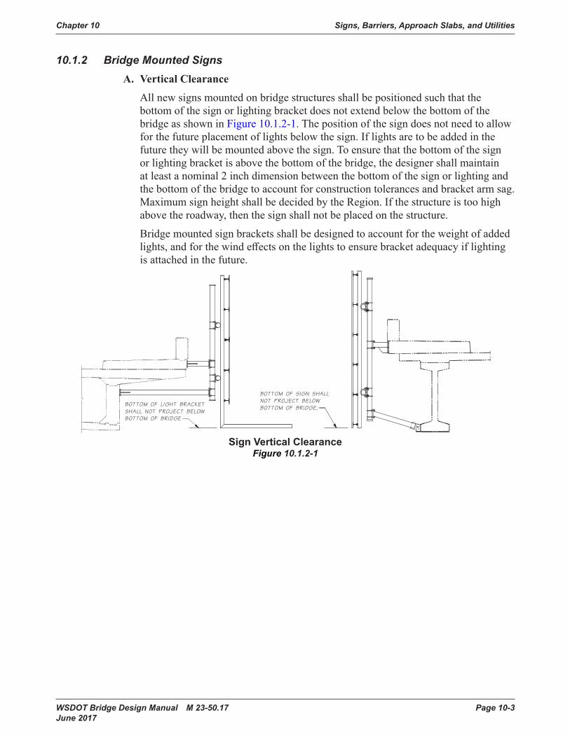
Allnewsignsmountedonbridgestructuresshallbepositionedsuchthatthebottomofthesignorlightingbracketdoesnotextendbelowthebottomofthebridge as shown in Figure 10.1.2-1. The position of the sign does not need to allow forthefutureplacementoflightsbelowthesign.Iflightsaretobeaddedinthefuturetheywillbemountedabovethesign.Toensurethatthebottomofthesignorlightingbracketisabovethebottomofthebridge,thedesignershallmaintainatleastanominal2inchdimensionbetweenthebottomofthesignorlightingandthebottomofthebridgetoaccountforconstructiontolerancesandbracketarmsag.MaximumsignheightshallbedecidedbytheRegion.Ifthestructureistoohighabove the roadway, then the sign shall not be placed on the structure.
Bridgemountedsignbracketsshallbedesignedtoaccountfortheweightofaddedlights,andforthewindeffectsonthelightstoensurebracketadequacyiflightingis attached in the future.
SignVerticalClearance
Figure 10.1.2-1
Signs, Barriers, Approach Slabs, and Utilities Chapter 10
Page 10-4 WSDOT Bridge Design Manual M 23-50.17 June 2017
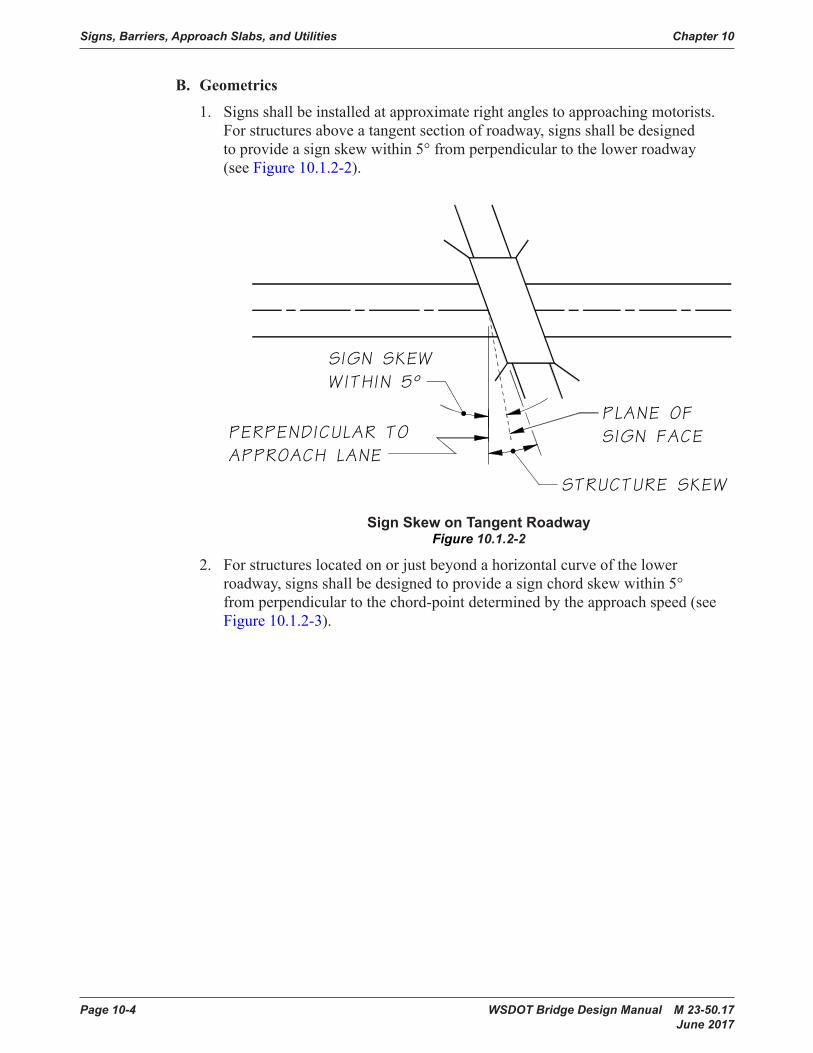
B. Geometrics
1. Signsshallbeinstalledatapproximaterightanglestoapproachingmotorists.For structures above a tangent section of roadway, signs shall be designed toprovideasignskewwithin5°fromperpendiculartothelowerroadway(see Figure 10.1.2-2).
SignSkewonTangentRoadwayFigure 10.1.2-2
2. Forstructureslocatedonorjustbeyondahorizontalcurveofthelowerroadway, signs shall be designed to provide a sign chord skew within 5° fromperpendiculartothechord-pointdeterminedbytheapproachspeed(seeFigure 10.1.2-3).

Chapter 10 Signs, Barriers, Approach Slabs, and Utilities
WSDOT Bridge Design Manual M 23-50.17 Page 10-5 June 2017
3. The top of the sign shall be level.
SignSkewonCurvedRoadwayFigure 10.1.2-3
Figure 10.1.2-4
Signs, Barriers, Approach Slabs, and Utilities Chapter 10
Page 10-6 WSDOT Bridge Design Manual M 23-50.17 June 2017
C. Aesthetics
1. Thesupportstructureshallnotextendbeyondthelimitsofthesignunlesstheextension is unavoidable.
2. Thesignsupportshallbedetailedinsuchamannerthatwillpermitthesignand lighting bracket to be installed level.
3. When the sign support will be exposed to view, special consideration is requiredindeterminingmembersizesandconnectionstoprovideaspleasingan appearance as possible.
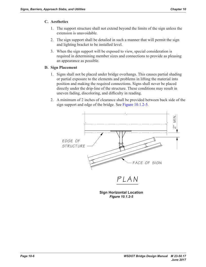
D. Sign Placement
1. Signs shall not be placed under bridge overhangs. This causes partial shading orpartialexposuretotheelementsandproblemsinliftingthematerialintopositionandmakingtherequiredconnections.Signsshallneverbeplaceddirectlyunderthedrip-lineofthestructure.Theseconditionsmayresultinunevenfading,discoloring,anddifficultyinreading.
2. Aminimumof2inchesofclearanceshallbeprovidedbetweenbacksideofthesign support and edge of the bridge. See Figure 10.1.2-5.
SignHorizontalLocationFigure 10.1.2-5
Chapter 10 Signs, Barriers, Approach Slabs, and Utilities
WSDOT Bridge Design Manual M 23-50.17 Page 10-7 June 2017
E. Installation
1. Resin bonded anchors or cast-in-place ASTM F593 Group 1 Condition A anchor rods shall be used to install the sign brackets on the structure. Size andminimuminstallationdepthshallbegivenintheplansorspecifications.Theresinbondedanchorsshallbeinstallednormaltotheconcretesurface.Resinbondedanchorsshallnotbeplacedthroughthewebsorflangesofprestressed or post-tensioned girders unless approved by the WSDOT Bridge Design Engineer. Resin bonded anchors shall not be used at overhead locations otherthanwithhorizontalhole/anchoralignment.
2. Bridgemountedsignstructuresshallnotbeplacedonbridgeswithsteelsuperstructures unless approved by the WSDOT Bridge Design Engineer.
F. Installing/Replacing New Sign on Existing Bracket Supports
When installing a new sign on existing bracket supports, the following shall be required:
1. All hardware shall be replaced per the current Standard Specifications.
2. The new sign area shall not exceed the original designed sign area.
3. The inspection report for the bracket shall be reviewed to ensure that the supports are in good condition. If there is not an inspection report, then an inspectionshallbeperformedonthebracket.
10.1.3 Monotube Sign Structures Mounted on BridgesA. Design Loads
Design loads for the supports of the Sign Bridges shall be calculated based on assuminga12-foot-deepsignovertheentireroadwaywidth,underthesignbridge,regardless of the sign area initially placed on the sign bridge. For Cantilever design loads,guidelinesspecifiedinSection10.1.1shallbefollowed.ThedesignloadsshallfollowthesamecriteriaasdescribedinSection10.1.1.Loadsfromthesignbridge shall be included in the design of the supporting bridge.
Incaseswhereasignstructureismountedonabridge,thesignstructure,fromthe anchor bolt group and above, shall be designed to AASHTO LRFD Standard Specifications for Structural Supports for Highway Signs, Luminaires, and Traffic SignalsFirstEdition,dated2015includinginterims.TheconcretetheanchorboltgroupandtheconnectingelementstothebridgestructureshallbedesignedtothespecificationsinthismanualandAASHTOLRFD.TheappropriateLRFDloadcombinationsfromthesignstructuredesigncodeshallbeusedwiththesameLRFDloadcombinationsfromthebridgedesigncode.
B. Vertical Clearance
VerticalclearanceforMonotubeSignStructuresshallbe20′-0″minimumfromthebottomofthelowestsigntothehighestpointinthetraveledlanes.SeeAppendix 10.1-A1-1, 10.1-A2-1, and 10.1-A3-1forsamplelocationsofMinimumVertical Clearances.

Signs, Barriers, Approach Slabs, and Utilities Chapter 10
Page 10-8 WSDOT Bridge Design Manual M 23-50.17 June 2017
C. Geometrics
Signstructuresshallbeplacedatapproximaterightanglestoapproachingmotorists.DimensionsanddetailsofsignstructuresareshownintheStandardPlans G-60.10, G-60.20, G-60.30, G-70.10, G-70.20, G-70.30 and Appendix 10.1-A1-1, 10.1-A1-2, and 10.1-A1-3 and 10.1-A2-1, 10.1-A2-2, and 10.1-A2-3.Whenmaintenancewalkwaysareincluded,refertoStandardPlansG-95.10,G-95.20, G-95.30.
10.1.4 Monotube Sign StructuresA. Sign Bridge Conventional Design
Table10.1.4-1providestheconventionalstructuraldesigninformationtobeusedfor a Sign Bridge Layout, Appendix 10.1-A1-1; along with the Structural Detail sheets, which are Appendix 10.1-A1-2 and Appendix 10.1-A1-3; General Notes, Appendix 10.1-A5-1; and Miscellaneous Details, Appendix 10.1-A5-2.
B. Cantilever Conventional Design
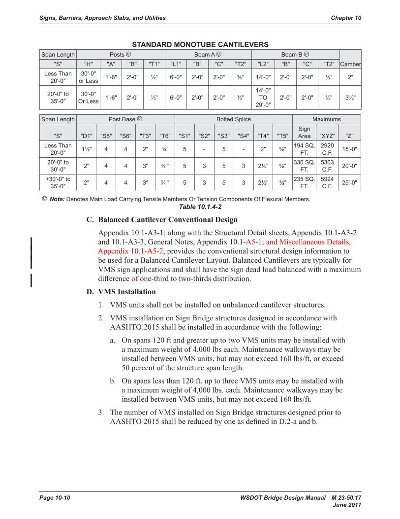
Table 10.1.4-2providestheconventionalstructuraldesigninformationtobeusedfor a Cantilever Layout, Appendix 10.1-A2-1; along with the Structural Detail sheets, which are Appendix 10.1-A2-2 and Appendix 10.1-A2-3; General Notes, Appendix 10.1-A5-1; and Miscellaneous Details, Appendix 10.1-A5-2.

Chapter 10 Signs, Barriers, Approach Slabs, and Utilities
WSDOT Bridge Design Manual M 23-50.17 Page 10-9 June 2017
STANDARDMONOTUBESIGNBRIDGESSPAN
LENGTH POSTS ¦ BEAM A ¦ BEAM B ¦ BEAM C ¦ BEAM D ¦ CAMBER"S" "H" "A" "B" "T1" "L1" "B" "C" "T2" "L2" "B" "C" "T2" "L3" "B" "C" "T2"
LESS THAN 60'-0"
30'-0" OR
LESS1'-6" 2'-0" ½" 6'-0" 2'-0" 2'-0" ½" 0'-0" 2'-0" 2'-0" ½"
13'-0" TO
48'-0"2'-0" 2'-0" ½" - - - - 2¾"
60'-0" TO
75'-0"
30'-0" OR
LESS1'-6" 2'-3" ⅝" 6'-0" 2'-3" 2'-0" ⅝"
9'-0" TO
14'-0"2'-3" 2'-0" ⅝"
30'-0" TO
35'-0"2'-3" 2'-0" ⅝" - - - - 3¾"
+75'-0" TO
90'-0"
30'-0" OR
LESS1'-6" 2'-3" ⅝" 6'-0" 2'-3" 2'-0" ⅝"
14'-0" TO
19'-0"2'-3" 2'-0" ⅝"
35'-0" TO
40'-0"2'-3" 2'-0" ⅝" - - - - 5"
+90'-0" TO
105'-0"
30'-0" OR
LESS1'-9" 2'-6" ⅝" 6'-0" 2'-6" 2'-3" ⅝"
19'-0" TO
26'-6"2'-6" 2'-3" ⅝" 40'-0" 2'-6" 2'-3" ⅝" - - - - 6"
+105'-0" TO
120'-0"
30'-0" OR
LESS1'-9" 2'-6" ⅝" 6'-0" 2'-6" 2'-3" ⅝"
26'-6" TO
34'-0"2'-6" 2'-3" ⅝" 40'-0" 2'-6" 2'-3" ⅝" - - - - 7½"
+120'-0" TO
135'-0"
30'-0" OR
LESS2'-0" 2'-6" ⅝" 6'-0" 2'-6" 2'-6" ⅝"
34'-0" TO
41'-6"2'-6" 2'-6" ⅝" 40'-0" 2'-6" 2'-6" ⅝" - - - - 8½"
+135'-0" TO
150'-0"
30'-0" OR
LESS2'-0" 2'-6" ⅝" 6'-0" 2'-6" 2'-6" ⅝"
41'-6" TO
49'-0"2'-6" 2'-6" ⅝" 40'-0" 2'-6" 2'-6" ⅝" - - - - 10½"
+150'-0" TO
165'-0"
30'-0" OR
LESS2'-0" 2'-8" ¾" 6'-0" 2'-8" 2'-8" ⅝" 27'-0" 2'-8" 2'-8" ⅝"
18'-5" TO
25'-6"2'-8" 2'-8" ⅝" 48'-0"2'-8" 2'-8" ⅝" 13¾"
+165'-0" TO
180'-0"
30'-0" OR
LESS2'-0" 2'-8" ¾" 6'-0" 2'-8" 2'-8" ⅝" 30'0" 2'-8" 2'-8" ⅝"
22'-6" TO
30'-0"2'-8" 2'-8" ⅝" 48'-0"2'-8" 2'-8" ⅝" 15¾"
SPAN LENGTH POST BASE ¦
BOLTED SPLICE #1 L1 TO L2 AND L1 TO L3
BOLTED SPLICE #2 L2 TO L3
BOLTED SPLICE #3 L3 TO L4
MAX SIGN AREA"S" "D1" "S5" "S6" "T3" "T6" "S1" "S2" "S3" "S4" "T4" "T5" "S1" "S2" "S3" "S4" "T4" "T5" "S1" "S2" "S3" "S4" "T4" "T5"
LESS THAN 60'-0"
1½" 4 4 3" ¾" 5 - 5 - 2" ⅝" - - - - - - - - - - - - 600 SQ . FT .
60'-0" TO
75'-0"1¾" 4 4 3" ¾" 6 - 5 - 2" ⅝" 6 - 5 - 2¼" ¾" - - - - - - 700
SQ FT .
+75'-0" TO
90'-0"1¾" 4 4 3" ¾" 6 - 5 - 2" ⅝" 6 - 5 - 2¼" ¾" - - - - - - 800 SQ .
FT .
+90'-0" TO
105'-0"1¾" 4 5 3" 1" 7 - 6 - 2" ⅝" 7 5 6 4 2½" 1" - - - - - - 900 SQ .
FT .
+105'-0" TO
120'-0"1¾" 4 5 3" 1" 7 - 6 - 2" ⅝" 7 5 6 4 2½" 1" - - - - - - 900 SQ .
FT .
+120'-0" TO
135'-0"2" 4 5 3" 1" 7 5 7 5 2" ⅝" 7 5 7 5 2½" 1" - - - - - - 900 SQ .
FT .
+135'-0" TO
150'-0"2" 4 5 3" 1" 7 5 7 5 2" ⅝" 7 5 7 5 2½" 1" - - - - - - 900 SQ .
FT .
+150'-0" TO
180'-0"2" 4 5 3" 1" 7 5 7 5 2" ⅝" 7 5 7 5 2½" 1" 7 5 7 5 2½" 1" 900 SQ .
FT .
¦ NOTE: DENOTES MAIN LOAD CARRYING TENSILE MEMBERS OR TENSION COMPONENTS OF FLEXURAL MEMBERS .Table 10.1.4-1
Signs, Barriers, Approach Slabs, and Utilities Chapter 10
Page 10-10 WSDOT Bridge Design Manual M 23-50.17 June 2017
STANDARDMONOTUBECANTILEVERSSpan Length Posts ¦ Beam A ¦ Beam B ¦
Camber"S" "H" "A" "B" "T1" "L1" "B" "C" "T2" "L2" "B" "C" "T2"Less Than
20'-0"30'-0"
or Less 1'-6" 2'-0" ½" 6'-0" 2'-0" 2'-0" ½" 14'-0" 2'-0" 2'-0" ½" 2"
20'-0" to 35'-0"
30'-0" Or Less 1'-6" 2'-0" ½" 6'-0" 2'-0" 2'-0" ½"
14'-0" TO
29'-0"2'-0" 2'-0" ½" 3½"
Span Length Post Base ¦ Bolted Splice Maximums
"S" "D1" "S5" "S6" "T3" "T6" "S1" "S2" "S3" "S4" "T4" "T5"Sign Area "XYZ" "Z"
Less Than 20'-0" 1½" 4 4 2" ¾" 5 - 5 - 2" ⅝" 194 SQ .
FT .2920 C .F . 15'-0"
20'-0" to 30'-0" 2" 4 4 3" ¾ " 5 3 5 3 2½" ⅝" 330 SQ .
FT .5363 C .F . 20'-0"
+30'-0" to 35'-0" 2" 4 4 3" ¾ " 5 3 5 3 2½" ⅝" 235 SQ .
FT .5924 C .F . 25'-0"
¦ Note: Denotes Main Load Carrying Tensile Members Or Tension Components Of Flexural Members .Table 10.1.4-2
C. Balanced Cantilever Conventional Design
Appendix 10.1-A3-1; along with the Structural Detail sheets, Appendix 10.1-A3-2 and 10.1-A3-3, General Notes, Appendix 10.1-A5-1; and Miscellaneous Details, Appendix 10.1-A5-2,providestheconventionalstructuraldesigninformationtobe used for a Balanced Cantilever Layout. Balanced Cantilevers are typically for VMSsignapplicationsandshallhavethesigndeadloadbalancedwithamaximumdifferenceof one-third to two-thirds distribution.
D. VMS Installation
1. VMS units shall not be installed on unbalanced cantilever structures.
2. VMS installation on Sign Bridge structures designed in accordance with AASHTO 2015 shall be installed in accordance with the following:
a. Onspans120ftandgreateruptotwoVMSunitsmaybeinstalledwithamaximumweightof4,000lbseach.MaintenancewalkwaysmaybeinstalledbetweenVMSunits,butmaynotexceed160lbs/ft,orexceed50 percent of the structure span length.
b. Onspanslessthan120ft.uptothreeVMSunitsmaybeinstalledwithamaximumweightof4,000lbs.each.MaintenancewalkwaysmaybeinstalledbetweenVMSunits,butmaynotexceed160lbs/ft.
3. ThenumberofVMSinstalledonSignBridgestructuresdesignedpriortoAASHTO2015shallbereducedbyoneasdefinedinD.2-aandb.

Chapter 10 Signs, Barriers, Approach Slabs, and Utilities
WSDOT Bridge Design Manual M 23-50.17 Page 10-11 June 2017
E. Monotube Sheet Guidelines
The following guidelines apply when using the Monotube Sign Structure Appendix 10.1-A1-1, 10.1-A1-2, and 10.1-A1-3; 10.1-A2-1, 10.1-A2-2, and 10.1-A2-3; 10.1-A3-1, 10.1-A3-2, and 10.1-A3-3; 10.1-A4-1, 10.1-A4-2, and 10.1-A4-3; and 10.1-A5-1, 10.1-A5-2, and 10.1-A5-3.
1. Each sign structure shall be detailed to specify:
a. SignstructurebaseElevation,Station,andNumber.
b. Type of Foundation 1, 2, or 3 shall be used for the Monotube Sign Structures, unless a non-conventional design is required. The average Lateral Bearing Pressure for each foundation shall be noted on the Foundationsheet(s).
c. If applicable, label the Elevation View “Looking Back on Stationing.”
2. Designersshallverifythecross-referencedpagenumbersanddetailsarecorrect.
F. Monotube Quantities
Quantities for structural steel are given in Table 10.1.4-3.SignStructureMaterialQuantities
ASTMA572GR.50orASTM588
Cantilever Sign Bridge
20’ <
20’ to 30’ Balanced 60’ <
60’ to 75’
75’ to 90’
90’ to
105’
105’ to
120’
120’ to
135’
135’ to
150’
150’ to
180’Post (plf) 132 132 132 132 176 176 204 204 215 215 267Base PL (lbs ./ea) 537 806 806 672 735 735 888 888 978 978 1029Beam, near Post (plf) 152 152 152 152 202 202 228 228 240 240 257Span Beam (plf) 152 152 152 152 202 202 228 228 240 240 257Corner Stiff . (lbs./ea set) 209 209 115 218 272 272 354 354 376 376 425Splice Pl #1 (lbs/pair) 592 706 706 578 650 650 826 826 1116 1116 1295Splice Pl #2 (lbs/pair) -- -- -- -- 730 730 1002 1002 1116 1116 1295Splice Pl #3 (lbs/pair) -- -- -- -- -- -- -- -- -- -- 1295Brackets (lbs ./ea) 60 60 60 60 65 65 69 69 70 70 706” Hand Hole (lbs ./ea) 18 18 18 18 18 18 18 18 18 18 186” x 11” Hand Hole (lbs ./ea) 30 30 30 30 30 30 18 30 30 30 30Anchor Bolt PL (lbs ./ea) 175 175 175 175 185 185 311 311 326 326 326Cover Plates (lbs ./ea) 65 65 65 -- -- -- -- -- -- -- --
SignStructureSteelQuantitiesTable 10.1.4-3
Signs, Barriers, Approach Slabs, and Utilities Chapter 10
Page 10-12 WSDOT Bridge Design Manual M 23-50.17 June 2017
10.1.5 FoundationsA. Monotube Sign Structure Foundation Types
The foundation type is to be used shall be based on the geotechnical investigation performedandgeotechnicalreportcompletedbythegeotechnicalengineerofrecord. Standard foundation designs for standard plan truss-type sign structures are provided in WSDOT Standard Plans G-60.20 and G-60.30 and G-70.20 andG-70.30.MonotubesignstructurefoundationsareBridgeDesignOfficeconventional designs and shall be as described in the following paragraphs:
1. Foundation Type 1, is the preferred foundation type. A foundation Type 1 consists of a drilled shaft with its shaft cap. The design of the shaft depths shown in the Sign Bridge Standard Drawings are based on a lateral bearing pressure of 2,500 psf. The designer shall check these shaft depths using AASHTO LRFDmethodology.ForType1foundationdetailsandshaftdepths see Sign Bridge Standard Drawings 10.1-A4-1 and 10.1-A4-2. The Geotechnical report for Foundation Type 1 should include the soil friction angle, soilunitweight,allowablebearingpressureandtemporarycasingifrequired.TemporarycasingshallbeproperlydetailedinallFoundationType1sheetsiftheGeotechnicalEngineerrequiresthem.
2. Foundation Type 2 is an alternate to Type 1 when drilled shafts are not suitable to the site. Foundation Type 2 is designed for a lateral bearing pressure of 2,500 psf. See Appendix 10.1-A4-3 for Foundation Type 2 Bridge Design Officeconventionaldesigninformation.The designer shall check these shaft depths using LRFDmethodology.
3. Foundation Type 3 replaces the foundation Type 2 for poor soil conditions where the lateral bearing pressure is between 2,500 psf and 1,500 psf. See Bridge Standard Drawing 10.1-A4-3 for Type 3 Foundation Bridge Design Officeconventionaldesigninformation.The designer shall check these shaft depths using LRFDmethodology.
4. Barrier Shape Foundations are foundations that include a barrier shape cap on the top portion of Foundation Types 1, 2, and 3. Foundation details shall be modifiedtoincludeBarrierShapeCapdetails.Appendix 10.1-A5-1 details a single slope barrier.
B. Luminaire, Signal Standard, and Camera Pole Foundation Types
LuminairefoundationoptionsareshownonStandardPlanJ-28.30.SignalStandardandCameraPolefoundationoptionsareprovidedonStandardPlansJ-26.10andJ-29.10 respectively.
C. Foundation Design
Shaft type foundations constructed in soil for sign bridges, cantilever sign structures,luminaires,signalstandardsandstrainpolesshall be designed in accordance with the current edition of the AASHTO LRFD Standard Specifications for Highway Signs, Luminaires, and Traffic Signals; Section 13.6 Drilled Shafts.
Chapter 10 Signs, Barriers, Approach Slabs, and Utilities
WSDOT Bridge Design Manual M 23-50.17 Page 10-13 June 2017
No provisions for foundation torsional capacity are provided in Section 10.13 of the AASHTO LRFD Standard Specifications for Highway Signs, Luminaires, and Traffic Signals. The following approach can be used to calculate torsional capacity ofsignstructure,luminaire,andsignalstandardfoundations:
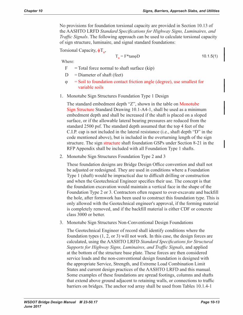
Torsional Capacity, φTn,Tn=F*tanφD 10 .1 .5(1)
Where:F =Totalforcenormaltoshaftsurface(kip)D =Diameterofshaft(feet)φ =Soiltofoundationcontactfrictionangle(degree),usesmallestfor
variable soils
1. Monotube Sign Structures Foundation Type 1 Design
Thestandardembedmentdepth“Z”,showninthetableonMonotube Sign Structure Standard Drawing 10.1-A4-1,shallbeusedasaminimumembedmentdepthandshallbeincreasediftheshaftisplacedonaslopedsurface,oriftheallowablelateralbearingpressuresarereducedfromthestandard2500psf.Thestandarddepthassumedthatthetop4feetoftheC.I.P. cap is not included in the lateral resistance (i.e., shaft depth “D” in the codementionedabove),butisincludedintheoverturninglengthofthesignstructure. The sign structure shaft foundation GSPs under Section 8-21 in the RFP Appendix shall be included with all Foundation Type 1 shafts.
2. Monotube Sign Structures Foundation Type 2 and 3
ThesefoundationdesignsareBridgeDesignOfficeconventionandshallnotbeadjustedorredesigned.TheyareusedinconditionswhereaFoundationType1(shaft)wouldbeimpracticalduetodifficultdrillingorconstructionandwhentheGeotechnicalEngineerspecifiestheiruse.TheconceptisthatthefoundationexcavationwouldmaintainaverticalfaceintheshapeoftheFoundationType2or3.Contractorsoftenrequesttoover-excavateandbackfillthehole,afterformworkhasbeenusedtoconstructthisfoundationtype.ThisisonlyallowedwiththeGeotechnicalengineer'sapproval,iftheformingmaterialiscompletelyremoved,andifthebackfillmaterialiseitherCDForconcreteclass 3000 or better.
3. Monotube Sign Structures Non-Conventional Design Foundations
The Geotechnical Engineer of record shall identify conditions where the foundationtypes(1,2,or3)willnotwork.Inthiscase,thedesignforcesarecalculated, using the AASHTO LRFD Standard Specifications for Structural Supports for Highway Signs, Luminaires, and Traffic Signals, and applied atthebottomofthestructurebaseplate.Theseforcesarethenconsideredservice loads and the non-conventional design foundation is designed with theappropriateService,Strength,andExtremeLoadCombinationLimitStatesandcurrentdesignpracticesoftheAASHTOLRFDandthismanual.Someexamplesofthesefoundationsarespreadfootings,columnsandshaftsthatextendabovegroundadjacenttoretainingwalls,orconnectionstotrafficbarriersonbridges.TheanchorrodarrayshallbeusedfromTables10.1.4-1
Signs, Barriers, Approach Slabs, and Utilities Chapter 10
Page 10-14 WSDOT Bridge Design Manual M 23-50.17 June 2017
and10.1.4-2andshallbelongenoughtodeveloptherodsintotheconfinedconcretecoreofthefoundation.Therodlengthandthereinforcementforconcreteconfinement,showninthetopfourfeetoftheFoundationType1,shallbeusedasaminimum.
4. Signal Foundation Design
ThetrafficsignalstandardGSPsunderSection8-20shallapplyforfoundationsin substandard soils.
D. Foundation Quantities
1. BarrierquantitiesareapproximateandcanbeusedforallFoundationTypes:
Class4000Concrete 7.15CY(overshaftfoundation) Grade 60 Rebar 372 lbs
2. Miscellaneoussteelquantities(anchorrods,anchorplate,andtemplate)forallMonotubeSignStructurefoundationtypesarelistedbelow(perfoundation).Quantities vary with span lengths as shown.
60feetandunder = 1,002pounds 61feetto90feet = 1,401pounds 91feetto120feet = 1,503pounds 121feetto180feet Barriermountedsignbridgenotrecommended for these spans.
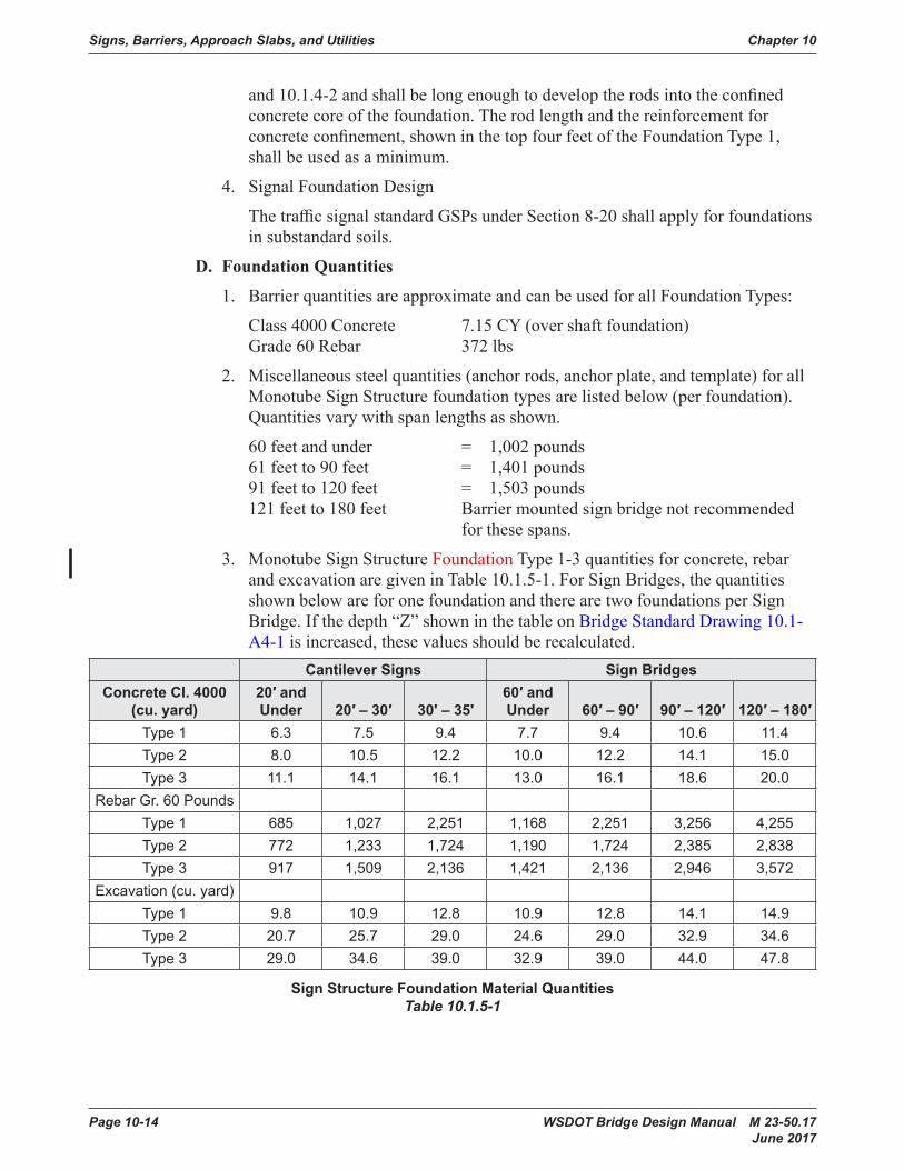
3. Monotube Sign Structure Foundation Type 1-3 quantities for concrete, rebar and excavation are given in Table 10.1.5-1. For Sign Bridges, the quantities shown below are for one foundation and there are two foundations per Sign Bridge. If the depth “Z” shown in the table on Bridge Standard Drawing 10.1-A4-1 is increased, these values should be recalculated.
CantileverSigns Sign BridgesConcreteCl.4000
(cu.yard)20′andUnder 20′–30′ 30'–35'
60′andUnder 60′–90′ 90′–120′ 120′–180′
Type 1 6 .3 7 .5 9 .4 7 .7 9 .4 10 .6 11 .4Type 2 8 .0 10 .5 12 .2 10 .0 12 .2 14 .1 15 .0Type 3 11 .1 14 .1 16 .1 13 .0 16 .1 18 .6 20 .0
Rebar Gr . 60 PoundsType 1 685 1,027 2,251 1,168 2,251 3,256 4,255Type 2 772 1,233 1,724 1,190 1,724 2,385 2,838Type 3 917 1,509 2,136 1,421 2,136 2,946 3,572
Excavation (cu . yard)Type 1 9 .8 10 .9 12 .8 10 .9 12 .8 14 .1 14 .9Type 2 20 .7 25 .7 29 .0 24 .6 29 .0 32 .9 34 .6Type 3 29 .0 34 .6 39 .0 32 .9 39 .0 44 .0 47 .8
SignStructureFoundationMaterialQuantitiesTable 10.1.5-1
Chapter 10 Signs, Barriers, Approach Slabs, and Utilities
WSDOT Bridge Design Manual M 23-50.17 Page 10-15 June 2017
10.1.6 Truss Sign Bridges: Foundation Sheet Design GuidelinesIf a Truss sign structure is used, refer to Standard Plans for foundation details. There arefouritemsthatshouldbeaddressedwhenusingtheStandard Plans, which are outlined below. For details for F-shape barrier details not shown in Standard Plans contactBridgeOfficetoaccessarchivedBridgeOfficedetails.
1. Determineconduitneeds.Ifnoneexist,deleteallreferencestoconduit.Ifconduitis required, verify with the Region as to size and quantity.
2. Showsignbridgebaseelevation,number,dimensionandstation.
3. The concrete barrier transition section shall be in accordance with the Standard Plans.
4. The quantities shall be based on the Standard Plans details as needed.
Signs, Barriers, Approach Slabs, and Utilities Chapter 10
Page 10-16 WSDOT Bridge Design Manual M 23-50.17 June 2017
10.2 BridgeTrafficBarriers10.2.1 General Guidelines
ThedesigncriteriafortrafficbarriersonstructuresshallbeinaccordancewithSection13oftheAASHTOLRFD.ThefollowingguidelinessupplementtherequirementsinAASHTOLRFD.
TheWSDOTBridgeandStructuresstandardfortrafficbarriersonnewbridgesandbridge approach slabs shall be a 42 inch Single Slope concrete barrier for all interstate routes,majorhighwayroutes,andoverNationalHighwaySystem(NHS)routesunlessspecialconditionsapply.The42inchrequirementisinaccordancewiththe“Fall Protection”requirementsoftheWashingtonStateDepartmentofLaborandIndustries,(WAC 296-155-24609 and WAC 296-155-24615 2a),andtheJuly2014AASHTOresolution for Fall Protection.
The WSDOT Bridge and Structures standard for existing bridges, bridge rehabilitation projects,StructuralEarthWallandGeosyntheticwalltrafficbarriers,retainingwalls,andmedianbarriershallbea34inchor42inchSingleSlopetrafficbarrier.
Useofa32inchor42inchFShapeconcretebarriershallbelimitedtolocationswherethere is F Shape concrete barrier on the approach grade to a bridge or for continuity within a corridor.
Useofa32inchPedestrianconcretebarriershallbelimitedtolocationswithsidewalk.
Useofa42inchor54inchcombinationbarrier(32inchor34inchconcretebarrierincreasedbymetalrailing)arelesseconomical,requiremoremaintenance,andshallbelimitedforpurposessuchasscenicroads.Foradditionalrequirementsforpedestrianand bicycle/pedestrian railings, see Section 10.5.1.
ItshallbetheBridgeandStructuresOfficepolicytodesigntrafficbarriersfornewstructuresusingminimumTestLevel4(TL-4)designcriteriaregardlessoftheheightof the barrier safety shape. The Test Level shall be indicated in the Bridge General NotesorGeneralNotes.ATestLevel5(TL-5)trafficbarriershallbeusedonnewstructures under the following conditions:• “T” intersections on a structure.• Barriers on structures with a radius of curvature less than 500 ft, TL-4 is adequate
for the barrier on the inside of the curve.• Greaterthan10percentAverageDailyTruckTraffic(ADTT)whereapproachspeedsare50mphorgreater(e.g.,freewayoff-ramps).
• Accident history suggests a need.• Protectionofschools,business,orotherimportantfacilitiesbelowthebridge.
See AASHTO LRFD Section 13 for additional Test Level selection criteria.
A list of crash tested barriers can be found through the FHWA website at: https://safety.fhwa.dot.gov/roadway_dept/countermeasures/reduce_crash_severity/listing.cfm?code=long
Chapter 10 Signs, Barriers, Approach Slabs, and Utilities
WSDOT Bridge Design Manual M 23-50.17 Page 10-17 June 2017
10.2.2 Bridge Railing Test LevelsItmustberecognizedthatbridgetrafficbarrierperformanceneedsdiffergreatlyfromsitetosite.Barrierdesignsandcostsshouldmatchfacilityneeds.ThisconceptisembodiedintheAASHTOLRFD.Sixdifferentbridgerailingtestlevels,TL-1thruTL-6,andassociatedcrashtest/performancerequirementsaregiveninAASHTOLRFDSection13alongwithguidancefordeterminingtheappropriatetestlevelfora given bridge.
10.2.3 Available WSDOT DesignsA. Service Level 1 (SL-1) Weak Post Guardrail (TL-2)
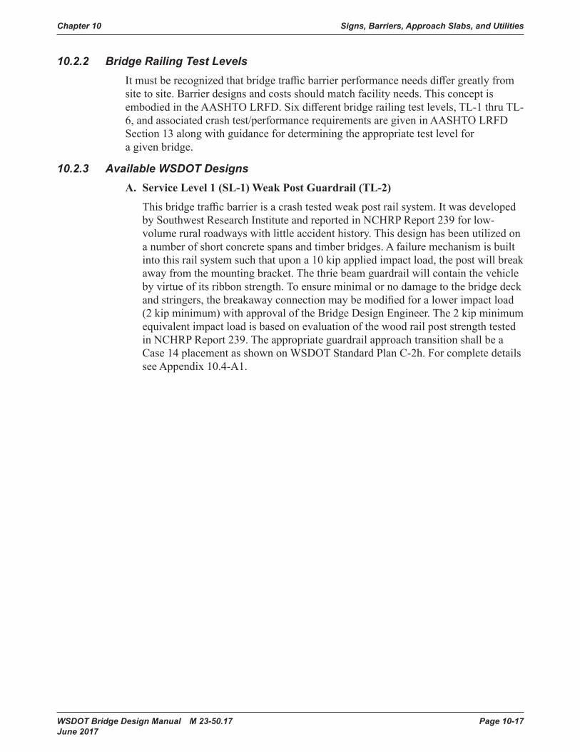
Thisbridgetrafficbarrierisacrashtestedweakpostrailsystem.Itwasdevelopedby Southwest Research Institute and reported in NCHRP Report 239 for low-volumeruralroadwayswithlittleaccidenthistory.Thisdesignhasbeenutilizedonanumberofshortconcretespansandtimberbridges.Afailuremechanismisbuiltintothisrailsystemsuchthatupona10kipappliedimpactload,thepostwillbreakawayfromthemountingbracket.Thethriebeamguardrailwillcontainthevehiclebyvirtueofitsribbonstrength.Toensureminimalornodamagetothebridgedeckandstringers,thebreakawayconnectionmaybemodifiedforalowerimpactload(2kipminimum)withapprovaloftheBridgeDesignEngineer.The2kipminimumequivalentimpactloadisbasedonevaluationofthewoodrailpoststrengthtestedin NCHRP Report 239. The appropriate guardrail approach transition shall be a Case14placementasshownonWSDOTStandard Plan C-2h.Forcompletedetailssee Appendix 10.4-A1.
Signs, Barriers, Approach Slabs, and Utilities Chapter 10
Page 10-18 WSDOT Bridge Design Manual M 23-50.17 June 2017
B. Texas T-411 Aesthetic Concrete Baluster (TL-2)
Texas developed this standard for a section of highway that was considered to beahistoriclandmark.TheexistingdeficientconcretebalusterrailwasreplacedwithamuchstrongerconcretebalusterthatsatisfactorilypassedthecrashtestperformancecriteriasetforthbytheNCHRPReport230.Fordetails,visitTXDOT’s Bridge and Structures website at www.txdot.gov/inside-txdot/division/bridge.html.
SL-1WeakPost TexasT-411Figure 10.2.3-1
C. Traffic Barrier – 32″ Shape F (TL-4)
Thisconfigurationwascrashtestedinthelate1960s,alongwiththeNewJerseyShape, under NCHRP 230 and again at this test level under NCHRP 350. The steeper vertical shape tested better than the New Jersey face and had less of aninclinationtorollvehiclesoveruponimpact.Forfuturedeckoverlays,anencroachmentof2.0in.,leavinga1.0in.liphasbeensatisfactorilytestedforsafetyshapes,seeAASHTOArticleC13.7.3.2.ForcompletedetailsseeBridgeStandardDrawings 10.2-A1 and 10.2-A2.

Chapter 10 Signs, Barriers, Approach Slabs, and Utilities
WSDOT Bridge Design Manual M 23-50.17 Page 10-19 June 2017
D. Traffic Barrier – 34″ Single Slope (TL-4)
ThisconcretetrafficbarriersystemwasdesignedbythestateofCaliforniainthe1990stospeedupconstructionbyusingthe“slipforming”methodofconstruction.ItwastestedunderNCHRP350.WSDOThasincreasedtheheightfrom32″to34″tomatchtheapproachtrafficbarrierheightandtoallowtheplacementofoneHMAoverlay.Duetoinherentproblemswiththe“slipforming”methodoftrafficbarrierconstructionWSDOThasincreasedtheconcretecoveronthetrafficsidefrom1½″to2½″.Forcompletedetails,seeBridge Standard Drawing 10.2-A3.
32″F-Shape 34″SingleSlopeFigure 10.2.3-2
E. Pedestrian Barrier (TL-4)
ThiscrashtestedrailsystemoffersasimpletobuildconcretealternativetotheNewJerseyandF-Shapeconfigurations.ThissystemwascrashtestedunderbothNCHRP230and350.Sincethetrafficfacegeometryisbetterforpedestriansandbicyclists,WSDOTusesthissystemprimarilyinconjunctionwithasidewalk.Forcompletedetails,see Bridge Standard Drawing 10.2-A4.

Signs, Barriers, Approach Slabs, and Utilities Chapter 10
Page 10-20 WSDOT Bridge Design Manual M 23-50.17 June 2017
F. Oregon 3-Tube Curb Mounted Traffic Barrier (TL-4)
Thisisanothercrashtestedtrafficbarrierthatoffersalightweight,see-throughoption.ThissystemwascrashtestedunderbothNCHRP230and350.Arigidthriebeamguardrailtransitionisrequiredatthebridgeends.Fordetails,seetheOregonBridge and Structure website at www.oregon.gov/ODOT/HWY/ENGSERVICES/Pages/bridge_drawings.aspx.
32″Vertical Oregon3-TubeFigure 10.2.3-3
G. Traffic Barrier – 42″ Shape F (TL-4 and TL-5)
Thisbarrierisverysimilartothe32″F-shapeconcretebarrierinthattheslopeofthefrontsurfaceisthesameexceptforheight.Forcompletedetails,seeBridge Standard Drawing 10.2-A6.
Chapter 10 Signs, Barriers, Approach Slabs, and Utilities
WSDOT Bridge Design Manual M 23-50.17 Page 10-21 June 2017
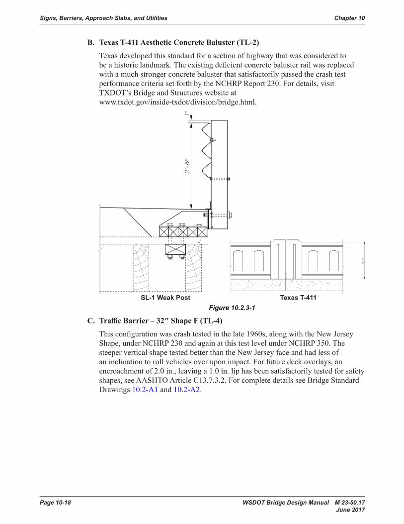
H. Traffic Barrier – 42″ Single Slope (TL-4 and TL-5)
ThisoptionoffersasimpletobuildalternativetotheShapeFconfiguration.ForcompletedetailsseeBridge Standard Drawing 10.2-A6.
42″F-Shape 42″SingleSlopeFigure 10.2.3-4
10.2.4 Design CriteriaA. Design Values
AASHTOLRFDAppendixA13shallbeusedtodesignbridgetrafficbarriersandtheirsupportingelements(i.e.thedeck).
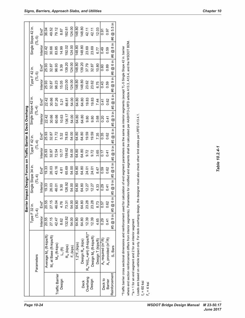
ConcretetrafficbarriersshallbedesignedusingyieldlineanalysisasdescribedinAASHTOLRFDA13.3.1.TheimpactloadsontrafficbarriersshallbeappliedattheheightspecifiedforintendedTestLevelsinaccordancetotheAASHTOLRFDTable A13.2-1 “Design Forces for Traffic Railing (32-inch for TL-4, and 42-inchforTL-5)”.WSDOTStandardFShapeandSingleSlopebarriersmeettheserequirements.
DeckoverhangssupportingtrafficbarriersshallbedesignedinaccordancewithAASHTOLRFDA13.4.ForconcretetrafficbarriersinDesignCase1,AASHTOrequires MS,thedeckoverhangflexuralresistance,tobegreaterthanMc of theconcretetrafficbarrierbase.Thisrequirementisconsistentwithyieldlineanalysis(seeAASHTOLRFDCA13.3.1),butresultsinoverconservativedeckoverhang designs.
Signs, Barriers, Approach Slabs, and Utilities Chapter 10
Page 10-22 WSDOT Bridge Design Manual M 23-50.17 June 2017
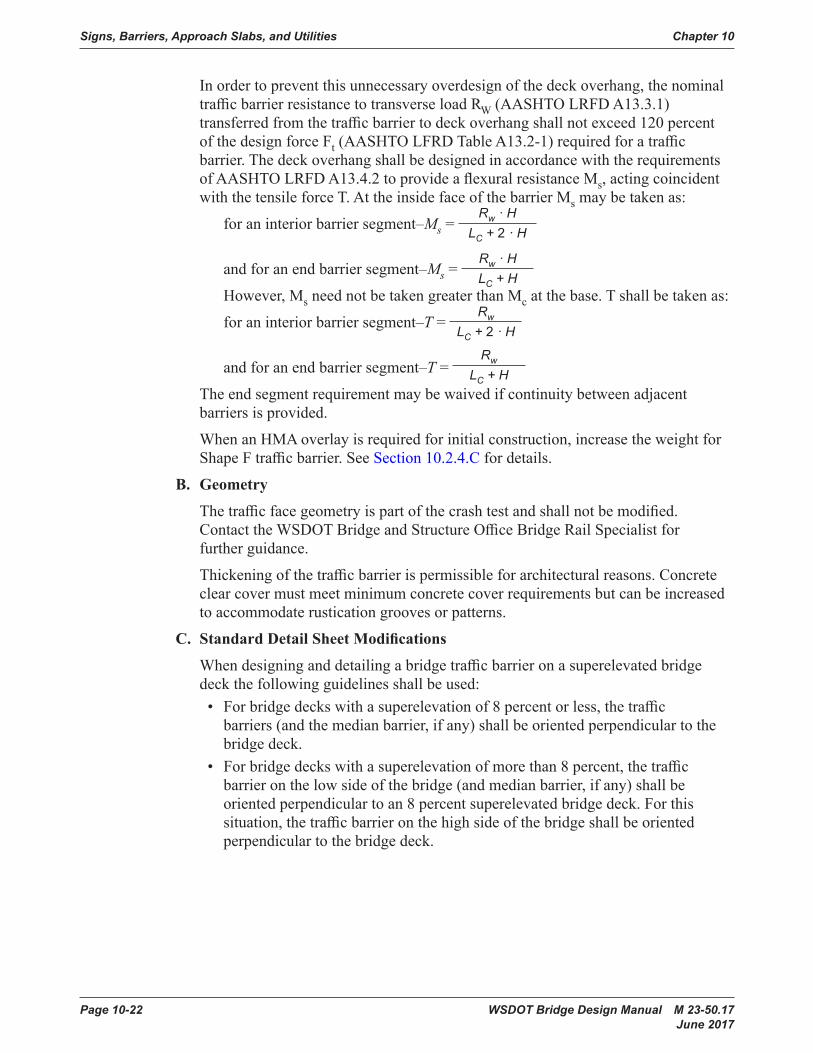
Inordertopreventthisunnecessaryoverdesignofthedeckoverhang,thenominaltrafficbarrierresistancetotransverseloadRW(AASHTOLRFDA13.3.1)transferredfromthetrafficbarriertodeckoverhangshallnotexceed120percentof the design force Ft(AASHTOLFRDTableA13.2-1)requiredforatrafficbarrier.ThedeckoverhangshallbedesignedinaccordancewiththerequirementsofAASHTOLRFDA13.4.2toprovideaflexuralresistanceMs, acting coincident with the tensile force T. At the inside face of the barrier Msmaybetakenas:
foraninteriorbarriersegment–Ms=Rw · H
LC + 2 · H
andforanendbarriersegment–Ms=Rw · H LC + H
However, Ms need not be taken greater than Mc at the base. T shall be taken as:
foraninteriorbarriersegment–T=Rw
LC + 2 · H
andforanendbarriersegment–T=Rw
LC + H Theendsegmentrequirementmaybewaivedifcontinuitybetweenadjacent
barriers is provided.
When an HMA overlay is required for initial construction, increase the weight for ShapeFtrafficbarrier.SeeSection 10.2.4.C for details.
B. Geometry
Thetrafficfacegeometryispartofthecrashtestandshallnotbemodified.ContacttheWSDOTBridgeandStructureOfficeBridgeRailSpecialistforfurther guidance.
Thickeningofthetrafficbarrierispermissibleforarchitecturalreasons.Concreteclearcovermustmeetminimumconcretecoverrequirementsbutcanbeincreasedtoaccommodaterusticationgroovesorpatterns.
C. Standard Detail Sheet Modifications
Whendesigninganddetailingabridgetrafficbarrieronasuperelevatedbridgedeck the following guidelines shall be used:• Forbridgedeckswithasuperelevationof8percentorless,thetrafficbarriers(andthemedianbarrier,ifany)shallbeorientedperpendiculartothebridge deck.
• Forbridgedeckswithasuperelevationofmorethan8percent,thetrafficbarrieronthelowsideofthebridge(andmedianbarrier,ifany)shallbeoriented perpendicular to an 8 percent superelevated bridge deck. For this situation,thetrafficbarrieronthehighsideofthebridgeshallbeorientedperpendicular to the bridge deck.
Chapter 10 Signs, Barriers, Approach Slabs, and Utilities
WSDOT Bridge Design Manual M 23-50.17 Page 10-23 June 2017
Thestandarddetailsheetsaregenericandmayneedtobemodifiedforeachproject.Thepermissiblemodificationsare:• Removaloftheelectricalconduit,junctionbox,anddeflectionfittingdetails.• Removalofdesignnotes.• Ifthetrafficbarrierdoesnotcontinueontoawall,removeW1andW2rebar
references.• Removalofthenon-applicableguardrailendconnectiondetailsandverbiage.• Ifguardrailisattachedtothetrafficbarrier,useeitherthethriebeamendsection“DesignF”detailorthew-beamendsection“DesignF”detail.Ifthetrafficbarriercontinuesoffthebridge,approachslab,orwall,removethefollowing:
• Guardraildetailsfromallsheets.• Conduitendflaredetail.• ModifiedendsectiondetailandR1AorR2Arebardetailsfromallsheets.• End section bevel.• Increasethe3″toedimensionoftheShapeFtrafficbarriersupto6″toaccommodateHMAoverlays.
Signs, Barriers, Approach Slabs, and Utilities Chapter 10
Page 10-24 WSDOT Bridge Design Manual M 23-50.17 June 2017
Tabl
e 10
.2.4
-1
Inte
rior
End*
Inte
rior
End*
Inte
rior
End*
Inte
rior
End*
Inte
rior
End*
Inte
rior
End*
Aver
age
Mc (
ft-ki
ps/ft
)20
.55
20 .5
519
.33
19 .3
325
.93
25 .9
322
.42
22 .4
225
.93
25 .9
322
.42
36 .0
4M
c at B
ase
(ft-k
ips/
ft)27
.15
27 .1
526
.03
26 .0
332
.87
32 .8
730
.66
30 .6
632
.87
32 .8
730
.66
49 .5
2M
w (f
t-kip
s)42
.47
46 .0
446
.01
43 .1
672
.54
71 .7
260
.66
57 .2
698
.23
96 .9
383
.85
79 .1
2L c
(ft)
8 .62
4 .76
9 .30
4 .81
10 .7
75 .
3210
.63
5 .21
15 .0
59 .
3914
.99
8 .87
Rw (k
ips)
132 .
8273
.31
126 .
9265
.69
159 .
6278
.83
136 .
1766
.81
223 .
0013
9 .20
192 .
0218
2 .61
F t (k
ips)
54 .0
054
.00
54 .0
054
.00
54 .0
054
.00
54 .0
054
.00
124 .
0012
4 .00
124 .
0012
4 .00
1 .2*
F t (k
ips)
64 .8
064
.80
64 .8
064
.80
64 .8
064
.80
64 .8
064
.80
148 .
8014
8 .80
148 .
8014
8 .80
Des
ign
Rw (k
ips)
64 .8
064
.80
64 .8
064
.80
64 .8
064
.80
64 .8
064
.80
148 .
8013
9 .20
148 .
8014
8 .80
Rw*H
/(Lc+
aH) (
ft-ki
ps/ft
)**
12 .3
923
.28
12 .2
724
.01
9 .72
19 .5
99 .
8019
.83
23 .6
237
.79
23 .6
942
.11
Des
ign
Ms (
ft-ki
ps/ft
)12
.39
23 .2
812
.27
24 .0
19 .
7219
.59
9 .80
19 .8
323
.62
32 .8
723
.69
42 .1
1D
esig
n T
(kip
s/ft)
4 .65
8 .73
4 .33
8 .47
3 .65
7 .35
3 .68
7 .44
6 .75
10 .8
06 .
7712
.03
A s re
quire
d (in
2 /ft)
0 .29
0 .57
0 .29
0 .59
0 .17
0 .35
0 .20
0 .41
0 .43
0 .60
0 .49
0 .91
A s p
rovi
ded
(in2 /ft
)0 .
410 .
620 .
410 .
620 .
410 .
620 .
410 .
620 .
590 .
890 .
590 .
97S 1
Bar
s#5
@ 9
in#5
@ 6
in#5
@ 9
in#5
@ 6
in#5
@ 9
in#5
@ 6
in#5
@ 9
in#5
@ 6
in#6
@ 9
in#6
@ 6
in#6
@ 8
in#6
@ 5
.5 in
*Tra
ffic
barri
er c
ross
sec
tiona
l dim
ensi
ons
and
rein
forc
emen
t use
d fo
r cal
cula
tion
of e
nd s
egm
ent p
aram
eter
s ar
e th
e sa
me
as in
terio
r seg
men
ts (e
xcep
t TL-
5 Si
ngle
Slo
pe 4
2 in
. bar
rier
whe
re e
nd s
ectio
n re
info
rcem
ent d
iffer
s fro
m in
terio
r seg
men
ts) .
Para
met
ers
for m
odifi
ed e
nd s
egm
ents
sha
ll be
cal
cula
ted
per A
ASH
TO-L
RFD
arti
cle
A13 .
3, A
13 .4
, and
the
WSD
OT
BDM
.**
a =
1 fo
r an
end
segm
ent a
nd 2
for a
n in
terio
r seg
men
tLo
ads
are
base
d on
veh
icle
impa
ct o
nly .
For
dec
k ov
erha
ng d
esig
n, th
e de
sign
er m
ust a
lso
chec
k ot
her l
imit
stat
es p
er L
RFD
A13
.4 .1
.f v
= 60
ksi
f' c=
4 ks
i
Barrie
rImpactDesignFo
rcesonTrafficBarrie
r&DeckOverhang
(TL-
5)(T
L-5)
Traf
fic B
arrie
r D
esig
n
Dec
k O
verh
ang
Des
ign
Type
F 4
2 in
.Si
ngle
Slo
pe 4
2 in
.
Dec
k to
Ba
rrier
R
einf
orce
men
tPara
met
ers
Type
F 3
2 in
.Si
ngle
Slo
pe 3
4 in
.Si
ngle
Slo
pe 4
2 in
.(T
L-4)
(TL-
4)(T
L-4)
Type
F 4
2 in
.(T
L-4)

Chapter 10 Signs, Barriers, Approach Slabs, and Utilities
WSDOT Bridge Design Manual M 23-50.17 Page 10-25 June 2017
D. Miscellaneous Design Information• Showthebackofpavementseatinthe“Plan–TrafficBarrier”detail.• Atroadwayexpansionjoints,showtrafficbarrierjointsnormaltocenterline
except as shown on sheets Appendix 9.1-A1-1 and 9.1-A2-1.• Whenanoverlayisrequired,the2′-8″minimumdimensionshowninthe“TypicalSection–TrafficBarrier”shallbereferencedtothetopoftheoverlay.
• When bridge lighting is part of the contract, include the lighting bracket anchorage detail sheet.
• Approximatequantitiesforthetrafficbarriersheetsare:
BarrierType ConcreteWeight(lb/ft) SteelWeight(lb/ft)32″ F-shape (3″ toe) 460 18 .632″ F-shape (6″ toe) 510 19 .1
34″ Single Slope 490 16 .142″ F-shape (3″ toe) 710 25 .842″ F-shape (6″ toe) 765 28 .4
42″ Single Slope 670 22 .932″ Pedestrian 640* 14 .7
Using concrete class 4000 with a unit weight of 155 lb/ft3
*with 6″ sidewalk, will vary with sidewalk thickness
• SteelReinforcementBars: S1 & S2 or S3 & S4 and W1 & W2bars(ifused)shallbeincludedintheBarList.
S1, S3, and W1 bars shall be epoxy coated.
Signs, Barriers, Approach Slabs, and Utilities Chapter 10
Page 10-26 WSDOT Bridge Design Manual M 23-50.17 June 2017
10.3 AtGradeConcreteBarriers10.3.1 DifferentialGradeConcreteBarriers
Thetopofthedifferentialgradeconcretebarriershallhaveaminimumwidthof6″.Ifaluminaireorsignistobemountedontopofthedifferentialgradeconcretebarrier,thenthewidthshallbeincreasedtoaccommodatethemountingplateand6″ofcleardistanceoneachsideoftheluminaireorsignpole.Thetransitionflarerateshallfollowthe Design Manual M 22-01.
A. Differential Grade Concrete Barriers
Concretebarriersatgradearesometimesrequiredinmedianareaswithdifferentroadway elevations on each side. The standard Single Slope barrier can be used for agradedifferenceupto10″fora2′-10″safetyshapeandupto6″fora3′-6″safetyshape. See Standard Plans C-70.10 and C-80.10 for details.
Ifthedifferenceingradeelevationsis4′-0″orless,thentheconcretebarriershallbedesignedasarigidsysteminaccordancewithAASHTOLRFDwiththefollowingrequirements:
1. All applicable loads shall be applied in accordance to AASHTO LRFD Section3.ThestructuralcapacityofthedifferentialgradeconcretebarrierandsupportingelementsshallbedesignedfortherequiredTestLevelvehicleimpactdesignforcesinaccordancewithAASHTOLRFDSections5and13.Anysectionalongthedifferentialgradebarrierandsupportingelementsshallnotfailinshear,bending,ortorsionwhenthebarrierissubjectedtotheTLimpactforces.
2. Forsoilloadswithoutvehicleimpactloads,theconcretebarriershallbe designed as a retaining wall (barrier weight resists overturning and sliding).Passivesoilresistancemaybeconsideredwithconcurrencebythegeotechnical engineer.
3. Vehicleimpactloadsshallbeappliedonthesideoftheconcretebarrierretainingsoilifthereistrafficonbothsides.ThevehicleimpactloadsshallbeappliedattheheightspecifiedforintendedTestLevelsinaccordancetotheAASHTO LRFD Section 13, Table A13.2-1 “Design Forces for Traffic Railing (32-inchforTL-4,and42-inchforTL-5)”.
4. Forsoilloadswithvehicleimpactloads,theAASHTOLRFDExtremeEventloading for vehicular collision shall also be analyzed. Equivalent Static Load (ESL)perNCHRPReport663maybeappliedasthetransversevehicleimpactload for evaluating sliding, bearing, and overturning only. For TL-3 and TL-4 barriersystems,theESLshallbe10kipsandforTL-5,theESLshallbe23 kips. The point of rotation for overturning shall be taken at the toe of barrier. Sliding resistance factor shall be 0.8 and overturning resistance factor shall be 0.5(supersedesAASHTO10.5.5.3.3).

Chapter 10 Signs, Barriers, Approach Slabs, and Utilities
WSDOT Bridge Design Manual M 23-50.17 Page 10-27 June 2017
5. The effective length of the concrete barrier required for stability shall be no morethan10timestheoverallheight, but not to exceed the length between barrierexpansionjoints(oroneprecastsection).Thebarriershallactasarigidbody behavior and shall be continuous throughout this length of barrier. Any couplingbetweenadjacentbarriersectionsorfrictionthatmayexistbetweenfree edges of barrier and the surrounding soil shall be neglected.
6. Aspecialimpactanalysisshallbeperformedatthebarrierendsifthebarrierterminateswithoutbeingconnectedtoarigidobjectordowelledtoanotherbarrier.Differentialbarrierdeflectionfrombarrierimpactmaycauseavehicleto“snag”ontheundeflectedbarrier.Thebarrierdepthmayneedtobeincreasedattheendtopreventthisdeflection.
7. Thedifferentialgradetrafficbarriershallhavedummyjointsat8to12footcentersbasedonprojectrequirements.
8. Fulldepthexpansionjointswithsheardowelsatthetopwillberequiredatintervalsbasedonanalysisbutnottoexceeda120′-0″maximumspacing.
9. Barrierbottomshallbeembeddedaminimum6″belowroadway.Roadwaysubgradeandballastshallbeextendedbelowwholewidthofdifferentialgradebarrier.
Mediantrafficbarrierswithagradedifferencegreaterthan4′-0″shallbedesignedasstandardplanretainingwallswithatrafficbarrieratthetopandabarriershapeat the cut face.
10.3.2 TrafficBarrierMomentSlabA. General
The guidelines provided herein are based on NCHRP Report 663 with the exceptionthataresistancefactorof0.5shallbeusedtodeterminerotationalresistance.ThisguidelineisapplicableforTL-3,TL-4,andTL-5barriersystemsasdefinedinSection13ofAASHTOLRFD Bridge Design Specifications.
Ls = 23 K Static Equivalent for TL5 Barriers
ha = Moment Arm Top of Barrier to Point of Rotations
Ls = 10 K Static Equivalent for TL3 and TL4 Barriers
La
Varies with Wall Type
Compacted Backfill
Roadway Base Course
Pavement Overburden
P
A = Point of Rotation
C.G.
W
Lw
GlobalStabilityofBarrier–MomentSlabSystemFigure 10.3.2-1

Signs, Barriers, Approach Slabs, and Utilities Chapter 10
Page 10-28 WSDOT Bridge Design Manual M 23-50.17 June 2017
B. Guidelines for Moment Slab Design
1. Structural Capacity
ThestructuralcapacityofthebarrierandconcretemomentslabshallbedesignedusingimpulseloadsatappropriateTestLevel(TL-3,TL-4,TL-5)appliedtothetopofthebarrierinaccordancewithSections5and13ofAASHTOLRFD.Anysectionalongthemomentslabshallnotfailinshear,bending,ortorsionwhenthebarrierissubjectedtothedesignimpactloads.ThetorsioncapacityofthemomentslabmustbeequaltoorgreaterthanthetrafficbarriermomentgeneratedbythespecifiedTLstaticequivalentofthevehicleimpulseload.
ThemomentslabshallbedesignedasadecksupportingbarrierinaccordancetoAASHTOLRFDA13.4.2asmodifiedbyBDMSection10.2.4.A.ThemomentslabreinforcementshallbedesignedtoresistcombinedforcesfromthemomentMS(kip-ft/ft)andthetensileforceT(kip/ft).MS and T are determinedfromthelesseroftheultimatetransverseresistanceofbarrierRW (kip)and120percentoftransversevehicleimpactforceFT (kip).MS is not to beexceededbytheultimatestrengthofbarrieratitsbaseMC (kip-ft/ft).
2. Global Stability
Bearingstress,sliding,andoverturningstabilityofthemomentslabshallbebasedonanEquivalentStaticLoad(ESL)appliedattheheightspecifiedforintended Test Levels in accordance to the AASHTO LRFD Section 13, Table A13.2-1 “Design Forces for Traffic Railing (32-inch for TL-4, and 42-inch for TL-5)”.ForTL-3andTL-4barriersystems,theESLshallbe10kips.ForTL-5barriersystems,theESLshallbe23kips.
TheEquivalentStaticLoad(ESL)isassumedtodistributeoverthelengthofcontinuousmomentslabthroughrigidbodybehavior.Barriershallalsobe continuous or have shear connections between barrier sections if precast throughoutthislengthofmomentslab.Anycouplingbetweenadjacentmomentslabsorfrictionthatmayexistbetweenfreeedgesofthemomentslabandthesurrounding soil should be neglected.
3. Minimum and Maximum Dimensions
Momentslabsshallhaveaminimumwidthof4.0feetmeasuredfromthepointofrotationtotheheeloftheslabandaminimumaveragedepthof0.83feet.Momentslabsmeetingtheseminimumrequirementsareassumedtoproviderigidbodybehavioruptoalengthof60feetlimitedtothelengthbetweenmomentslabjoints.
Rigidbodybehaviormaybeincreasedfrom60feettoamaximumof120feetifthetorsionalrigidityconstantofthemomentslabisproportionatelyincreasedandthereinforcingsteelisdesignedtoresistcombinedshear,moment,andtorsionfromTLstaticequivalentofthevehicleimpulseloads.
Forexample:RigidBodyLength=(J’/J60)x(60ft.)<120feet

Chapter 10 Signs, Barriers, Approach Slabs, and Utilities
WSDOT Bridge Design Manual M 23-50.17 Page 10-29 June 2017
Thetorsionalrigidityconstantformomentslabsshallbebasedonasolidrectangleusingthefollowingformula:
Where: 2a = total width of moment slab 2b = average depth of moment slab
For example: Minimum Moment Slab Width = 48 inches: a = 24 inches Minimum Moment Slab Average Depth = 10 inches: b = 5 inches J = J60 = 13,900 in4
4. Sliding of the Barrier
The factored static resistance to sliding (φP)ofthebarrier-momentslabsystemalong its base shall satisfy the following condition (Figure 2).
φP≥γLs (1)Where:
Ls = Equivalent Static Load (10 kips for TL-3 or TL-4, 23 kips for TL-5) φ = resistance factor (0.8) Supersedes AASHTO 10.5.5.3.3— Other Extreme Limit States γ = load factor (1.0) for TL-3 and TL-4 [crash tested extreme event] load factor (1.2) for TL-5 [untested extreme event] P = static resistance (kips)
P shall be calculated as:P=Wtanφr
(2)
Where: W = weight of the monolithic section of barrier and moment slab between joints or assumed length of rigid body behavior whichever is less, plus any material laying on top of the moment slab φr = friction angle of the soil on the moment slab interface (°)
Ifthesoil-momentslabinterfaceisrough(e.g.,castinplace),φr is equal to the friction angle of the soil φs.Ifthesoil-momentslabinterfaceissmooth(e.g.,precast),tanφr shall be reduced accordingly (0.8 tan φs).

Signs, Barriers, Approach Slabs, and Utilities Chapter 10
Page 10-30 WSDOT Bridge Design Manual M 23-50.17 June 2017
5. Overturning of the Barrier
Thefactoredstaticmomentresistance(φM)ofthebarrier-momentslabsystemto over-turning shall satisfy the following condition (Figure 1).
Thefactoredstaticmomentresistance(φM)ofthebarrier-momentslabsystemto overturning shall satisfy the following condition (Figure 1).
φM≥γLs ha (3)Where:
A = point of rotation, where the toe of the moment slab makes contact with compacted backfill adjacent to the fascia wall Lw = width of moment slab Ls = Equivalent Static Load (10 kips for TL-3 and TL-4) (23 kips for TL-5) φ = resistance factor (0.5) Supersedes AASHTO 10.5.5.3.3— Other Extreme Limit States and NCHRP Report 663 γ = load factor (1.0) for TL-3 and TL-4 [crash tested extreme event] load factor (1.2) for TL-5 [untested extreme event] ha = moment arm taken as the vertical distance from the point of impact due to the dynamic force (top of the barrier) to the point of rotation A M = static moment resistance (kips-ft) M shall be calculated as: M = W (La) (4) W = weight of the monolithic section of barrier and moment slab between joints or assumed length of rigid body behavior whichever is less, plus any material laying on top of the moment slab La = horizontal distance from the center of gravity of the weight W to point of rotation A
Themomentcontributionduetoanycouplingbetweenadjacentmomentslabs,shearstrengthoftheoverburdensoil,orfrictionwhichmayexistbetweenthebacksideofthemomentslabandthesurroundingsoilshallbeneglected.
C. Guidelines for the Soil Reinforcement
DesignofthesoilreinforcementshallbeinaccordancewiththeGeotechnical Design Manual Chapter 15.
D. Design of the Wall Panel
ThewallpanelsshallbedesignedtoresistthedynamicpressuredistributionsasdefinedintheGeotechnical Design Manual Chapter 15.
ThewallpanelshallhavesufficientstructuralcapacitytoresistthemaximumdesignruptureloadforthewallreinforcementdesignedinaccordancewiththeGeotechnical Design Manual Chapter 15.
The static load is not included because it is not located at the panel connection.

Chapter 10 Signs, Barriers, Approach Slabs, and Utilities
WSDOT Bridge Design Manual M 23-50.17 Page 10-31 June 2017
10.3.3 Precast Concrete BarrierA. Concrete Barrier Type 2
“Concrete Barrier Type 2” (see Standard Plan C-8)maybeusedonbridgesformedianapplicationsorfortemporarytrafficcontrolbasedonthefollowing guidelines:
1. Fortemporaryapplications,noanchorageisrequiredifthereis2feetorgreaterslidedistancebetweenthebackofthetrafficbarrierandanobjectand3feetorgreatertotheedgeofthebridgedeckoraseveredropoff(seeDesign Manual M22-01).
2. Forpermanentapplicationsinthemedian,noanchoragewillberequiredifthereisa3footorgreaterslidedistancebetweenthetrafficbarrierandthetrafficlane.
3. Fortemporaryapplications,thetrafficbarriershallnotbeplacedcloserthan9inchestotheedgeofabridgedeckorsubstantialdrop-offandshallbeanchored (see Standard Plans K-80.35 and K-80.37).
4. Thetrafficbarriershallnotbeusedtoretainsoilthatisslopedorgreaterthanthebarrierheightorsoilthatsupportsatrafficsurcharge.
B. Concrete Barrier Type 4 and Alternative Temporary Concrete Barrier
“Concrete Barrier Type 4 (see the Standard Plan C-8a),isnotafreestandingtrafficbarrier.Thisbarriershallbeplacedagainstarigidverticalsurfacethatisatleastastallasthetrafficbarrier.Inaddition,AlternativeTemporaryConcreteBarrierType4–NarrowBase(Standard Plan K-80.30)shallbeanchoredtothebridge deck as shown in Standard Plan K-80.37. The “Concrete Barrier Type 4 and AlternativeTemporaryConcreteBarrier”arenotdesignedforsoilretention.

Signs, Barriers, Approach Slabs, and Utilities Chapter 10
Page 10-32 WSDOT Bridge Design Manual M 23-50.17 June 2017
10.4 BridgeTrafficBarrierRehabilitation10.4.1 Policy
Thebridgetrafficbarrierretrofitpolicyis:“tosystematicallyimproveorreplaceexistingdeficientrailswithinthelimitsofroadwayresurfacingprojects.”Thisisaccomplishedby:• Utilizinganapprovedcrashtestedrailsystemthatisappropriateforthesiteor• Designingatrafficbarriersystemtothestrengthrequirementssetforthby
Section 2 of AASHTO Standard Specifications for Highway Bridges, 17th edition.
10.4.2 GuidelinesAstrengthandgeometricreviewisrequiredforallbridgerailrehabilitationprojects.Ifthestrengthoftheexistingbridgerailisunabletoresista10kipbarrierimpactdesignloadorhasnotbeencrashtested,thenmodificationsorreplacementwillberequiredtoimproveitsredirectionalcharacteristicsandstrength.Bridgesthathavedeficientbridgetrafficbarriersweredesignedtooldercodes.
TheAASHTOLFDloadof10kipsshallbeusedintheretrofitofexistingbridgetrafficbarriersystemsconstructedpriortotheyear2000.
TheuseoftheAASHTOLRFDcriteriatodesignbridgetrafficbarrierrehabswillresultinabridgedeckthathasinsufficientreinforcementtoresistmomentfromatrafficbarrierimpactloadandwillincreasetheretrofitcostduetoexpensivedeckmodifications.
IfthedesignofthebridgerehabilitationincludesotherbridgecomponentsthatwillbedesignedusingAASHTOLRFDthenthefollowingminimumequivalentExtremeEvent(CT)trafficbarrierloadingcanbeused:
Flexure=(1.3)*(1.67)*(10kip)/(0.9)=24.10kip Shear=(1.3)*(1.67)*(10kip)/(0.85)=25.54kip
10.4.3 Design CriteriaStandardthriebeamguardrailpostspacingis6′-3″exceptfortheSL-1WeakPost,which is at 8′-4″.Postspacingcanbeincreasedupto10′-0″ifthethriebeamguardrailisnested(doubledup).
Gaps in the guardrail are not allowed because they produce snagging hazards. The exceptions to this are:• Movablebridgesattheexpansionjointsofthemovablesections.• Attrafficgatesanddropdownnetbarriers.• At stairways.
Design F guardrail end sections will be used at the approach and trailing end of these gaps.
ForBridgeTrafficBarrierRehabilitationthefollowinginformationwillbeneededfromtheRegionDesignoffice:• BridgeSiteDataRehabilitationSheet–DOTForm235-002A.• Photos,preferablydigitalJPEGformat.
Chapter 10 Signs, Barriers, Approach Slabs, and Utilities
WSDOT Bridge Design Manual M 23-50.17 Page 10-33 June 2017
• Layoutwithexistingdimensions.• StandardPlanthriebeamguardrailtransitions(selectedbyRegionDesignoffice)tobeusedateachcornerofthebridge(contactbridgesandstructuresofficeforthriebeamheight).
• Location of any existing utilities.• MeasurementsofexistingACPtotopofcurbatthefourcorners,midpointsandthelocationsofminimumandmaximumdifference(fivelocationseachsideasaminimum).
• DiagramofthelocationofType3anchors,ifpresent,includingaplanviewwithverticalandhorizontaldimensionsofthelocationoftheType3anchorconnectionrelativetotheintersectingpointofthebackofpavementseatwiththecurbline.
• Theproposedoverlaytype,quantitiesofremovalandplacement.• Fortimberbridges,thefieldmeasurementofthedistancefromtheedgeofbridgedecktothefirstandsecondstringerisrequiredformountingplatedesign.
PlacementoftheretrofitsystemwillbedeterminedfromtheDesign Manual M22-01.Exceptionstothisarebridgeswithsidewalkstrengthproblems,pedestrianaccessissues,orvehiclesnaggingproblems.
10.4.4 WSDOT Bridge Inventory of Bridge RailsTheWSDOTBridgePreservationOfficemaintainsaninventoryofallbridgesinthestate on the State of Washington Inventory of Bridges.Concretebalustersaredeficientforcurrentlateralloadcapacityrequirements.Theyhaveapproximately3kipsofcapacitywhereas10kipsisrequired.Thecombinationhigh-baseconcreteparapetandmetalrailmayormaynotbeconsideredadequatedependingupontherailtype.ThemetalrailTypeR,S,andSBattached to the top of the high-base parapet are considered capable of resisting the required 5 kips of lateral load. Types 3, 1B, and 3A are considered inadequate. See the Design ManualM22-01forreplacementcriteria.
10.4.5 AvailableRetrofitDesignsA. Washington Thrie Beam Retrofit of Concrete Balusters Thissystemconsistsofthriebeamguardrailstiffeningofexistingconcrete
balusterrailswithtimberblockouts.TheSouthwestResearchInstituteconductedfull-scalecrashtestsofthisretrofitin1987.ResultsofthetestsweresatisfactoryandcompliedwithcriteriaforaTestLevel2(TL-2)categoryintheGuideSpecifications.ForcompletedetailsseeBridge Standard Drawing 10.4-A1-1.
B. New York Thrie Beam Guardrail Thiscrashtestedrailsystemcanbeutilizedatthetopofaraisedconcretesidewalk
toseparatepedestriantrafficfromthevehiculartrafficorcanbemounteddirectlytothetopoftheconcretedeck.ForcompletedetailsseeThrieBeamRetrofitConcreteCurb in Appendix 10.4-A1-3.
C. Concrete Parapet Retrofit ThisissimilartotheNewYorksystem.Forcompletedetailssee
Appendix 10.4-A1-2.

Signs, Barriers, Approach Slabs, and Utilities Chapter 10
Page 10-34 WSDOT Bridge Design Manual M 23-50.17 June 2017
D. SL-1 Weak Post Thisdesignhasbeenutilizedonsomeshortconcretespansandtimberbridges.
Afailuremechanismisbuiltintothisrailsystemsothatuponimpactwitha10kiploadthepostwillbreakawayfromthemountingbracket.Thethriebeamguardrailwillcontainthevehiclebyvirtueofitsribbonstrength.Toensureminimaldamagetothebridgedeckandstringers,thebreakawayconnectionmaybemodifiedforalowerimpactload(2kipminimum)withapprovaloftheBridgeDesignEngineer.Forcompletedetails,seeBridge Standard Drawing 10.4-A1-4.
10.4.6 AvailableReplacementDesignsA. Traffic Barrier – Shape F Retrofit ThisisWSDOT’spreferredreplacementofdeficienttrafficbarriersandparapetson
highvolumehighwayswithalargetruckpercentage.Allinterstatehighwaybridgesshallusethistypeofbarrierunlessspecialconditionsapply.Forcompletedetailssee Bridge Standard Drawing 10.4-A2.

Chapter 10 Signs, Barriers, Approach Slabs, and Utilities
WSDOT Bridge Design Manual M 23-50.17 Page 10-35 June 2017
10.5 BridgeRailing10.5.1 Design
WSDOT pedestrian and bicycle/pedestrian railings are designed in accordance with Chapter 13 in the AASHTO LRFD. The AASHTO LRFDcallsforaminimumof42″forbicyclerailingswhereasWSDOTrequiresaminimumheightof54″onstructures.The railings in Section 10.5.2 arenotdesignedforvehicularimpactloadsassuminglocationislowspeed,locationisoutsideofDesignClearZoneasdefinedintheDesign ManualChapter1600,orlocationhasminimalsafetyconsequencefromcollapseofrailing.Railingsforotherlocationsshallbedesignedforvehicularimpactloadsin accordance with Chapter 13 and/or 15 in the AASHTO LRFD.Emergencyandmaintenanceaccessshallbeconsidered.
Pedestrian and bicycle railings shall be designed using a Live Load factor of 1.75.
FallProtectionrailingshallmeettherequirementsofWAC296-155-24609.
10.5.2 Railing TypesA. Bridge Railing Type Pedestrian
Thispedestrianrailingisdesignedtositontopofthe32″and34″trafficbarriersandtomeetpedestrianheightrequirementsof42″.ForcompletedetailsseeBridge Standard Drawing 10.5-A1.
B. Bridge Railing Type BP and S-BP
TheserailingsaredesignedtomeetWSDOT’sminimumbicycleheightrequirementsof54″,andsitontopofthe32″and34″trafficbarriers.
There are two versions—the BP and S-BP. The BP is the standard railing and is madeoutofaluminum.TheS-BPisthesteelversiondesignedforuseinruralareasbecauseofaluminumtheft.ForcompletedetailsseeBridge Standard Drawing 10.5-A2 and 10.5-A3.
C. Pedestrian Railing
This railing is designed to sit on top of a six-inch curb on the exterior of a bridge sidewalk.Itmeetsthebicycleheightrequirementsof54″.ForcompletedetailsseeAppendix 10.5-A4.
D. Bridge Railing Type Chain Link Snow Fence and Bridge Railing Type Snow Fence
Thisrailingisdesignedtopreventlargechunksofplowedsnowfromfallingoffthebridgeontotrafficbelow.ForcompletedetailsseeAppendix10.5-A5-1through 10.5-A5-3.
E. Bridge Railing Type Chain Link Fence
Thisrailingisdesignedtominimizetheamountofobjectsfallingoffthebridgeontotrafficbelow.ForcompletedetailsseeAppendix10.5-A5-4.

Signs, Barriers, Approach Slabs, and Utilities Chapter 10
Page 10-36 WSDOT Bridge Design Manual M 23-50.17 June 2017
10.6 BridgeApproachSlabsBridgeapproachestypicallyexperiencetwotypesofsettlement,globalandlocal.Globalsettlementisconsolidationofthedeepernaturalfoundationsoils.Localsettlementismainlycompressionoffillmaterialsdirectlybeneaththeapproachpavementduetoconstruction.Thecombinationofglobalandlocalsettlementsadjacenttothebridgeendpiersformthecharacteristic“bump”inthepavementatthebridge.Theapproachslabsignificantlyreduceslocalsettlementandwillprovideatransitiontothelongtermroadwaydifferentialsettlements.Generally,abutmentswithadeepfoundationwillhavegreaterdifferentialroadwaysettlementsthanspreadfooting foundations.
When Are Bridge Approach Slabs Required–Bridgeapproachslabsarerequiredfor all new and widened bridges, except when concurrence is reached between the GeotechnicalBranch,theRegionDesignProjectEngineerOffice,andtheBridgeandStructuresOffice,thatapproachslabsarenotappropriateforaparticularsite.Inaccordance with Design Manual M 22-01, the State Geotechnical Engineer will include arecommendationinthegeotechnicalreportforabridgeonwhetherornotbridgeapproach slabs should be used at the bridge site. Factors considered while evaluating theneedforbridgeapproachslabsincludetheamountofexpectedsettlementandthetype of bridge structure.
Standard Plan A-40.50–TheStandard Plan A-40.50 is available for the Local Agencies(orothers)touseorreferenceinacontract.BridgeandStructuresOfficedesignswillprovidedetailedinformationinacustomizedapproachslabPlanViewandshow the approach slab length on the Bridge Layout Sheet.
Bridge Runoff–Bridgerunoffattheabutmentsshallbecarriedoffandcollectedatleast 10 feet beyond the bridge approach slab. Drainage structures such as grate inlets and catch basins shall be located in accordance with Standard Plan B-95.40 and the recommendationsoftheHydraulicsBranch.
Approach Pay Item–Allcostsinconnectionwithconstructingbridgeapproachslabsare included in the unit contract price per square yard for “Bridge Approach Slab.” Thepayitemincludessteelreinforcingbars,approachslabanchors,concrete,andcompressionseals.
10.6.1 NotestoRegionforPreliminaryPlanAllbridgepreliminaryplansshallshowapproachslabsattheendsofthebridges.IntheNotestoRegioninthefirstsubmittalofthePreliminaryPlantotheRegion,the designer shall ask the following questions:
1. Bridge approach slabs are shown for this bridge, and will be included in the Bridge PS&E.Doyouconcur?
2. Theapproachendsofthebridgeapproachslabsareshownnormaltothesurveyline(a)withor(b)withoutsteps(thedesignershallproposeonealternative).Doyouconcur?
3. Pleaseindicatethepavementtypefortheapproachroadway.

Chapter 10 Signs, Barriers, Approach Slabs, and Utilities
WSDOT Bridge Design Manual M 23-50.17 Page 10-37 June 2017
Dependingonthetypeandnumberofotherroadwayfeaturespresentatthebridgesite (such as approach curbs and barriers, drainage structures, sidewalks, utilities andconduitpipes)orspecialconstructionrequirementssuchasstagedconstruction,otherquestionsintheNotestoRegionpertainingtothebridgeapproachslabsmaybe appropriate.
Specialstagingconditionsexistwhentheabutmentskewisgreaterthan30°andforwideroadwaywidths.Thisincludesbridgewideningswith(orwithout)existingbridgeapproachslabs.Thepreliminaryplanshouldincludedetailsshowinghowtheseconditions are being addressed for the bridge approach slabs, and the designer shall include appropriate questions in the Notes to Region asking for concurrence with the proposed design.
10.6.2 Bridge Approach Slab Design CriteriaThe standard bridge approach slab design is based on the following criteria:
1. The bridge approach slab is designed as a slab in accordance with AASHTOLRFD.(StrengthLimitState,IM=1.33,noskew).
2. Thesupportattheroadwayendisassumedtobeauniformsoilreactionwithabearinglengththatisapproximately⅓thelengthoftheapproachslab,or25′/3=8′.
3. TheEffectiveSpanLength(Seff),regardlessofapproachlength,isassumedtobe: 25′approach–8′=17′
4. Longitudinalreinforcingbarsdonotrequiremodificationforskewedapproachesupto30degreesorforslablengthsgreaterthan25′.
5. Theapproachslabisdesignedwitha2″concretecovertothebottomreinforcing.
10.6.3 Bridge Approach Slab DetailingThebridgeapproachslabandlengthalongcenterlineofprojectshallbeshowninthePlan View of the Bridge Layout sheet. The Bridge Plans will also include approach slabinformationasshownin Bridge Standard Drawings 10.6-A1-1, 10.6-A1-2, and 10.6-A1-3.TheApproachSlabPlansheetsshouldbemodifiedasappropriatetomatchthebridgesiteconditions.ApproachslabPlanViewsshallbecustomizedforthespecificprojectandallirrelevantdetailsshallberemoved.
PlanViewdimensionsshalldefinetheplanareaoftheapproachslab.Theminimumdimensionfromthebridgeis25′.Ifthereareskewedends,thendimensionsshallbe provided for each side of the slab, or a skew angle and one side, in addition to thewidth.Forslabsonacurve,thelengthalongtheprojectlineandthewidthshallbe shown.
SimilartoBridgeTrafficBarrierdetailing,approachslabsteeldetailingshallshowsize,spacing,andedgeclearance.Thenumberandtotalspacescanbedeterminedbythecontractor.Ifapplicable,thetrafficbarrierAS1andAS2alongwiththeextratoptransverse bar in the slab shall be shown in the Plan View. AS1 bars shall be epoxy coated.AlsorememberthatthespacingoftheAS1barsdecreasesnearjoints.Whenthe skew is greater than 20 degrees, then AP8 bars shall be rotated at the acute corners of the bridge approach slab.

Signs, Barriers, Approach Slabs, and Utilities Chapter 10
Page 10-38 WSDOT Bridge Design Manual M 23-50.17 June 2017
Bendingdiagramsshallbeshownforallcustomreinforcement.AllBridgeApproachSlabsheetswillhavetheAP2andAP7bars.Ifthereisatrafficbarrier,thenAP8,AS1,and AS2 bars shall be shown.
Additionallayoutanddetailsmayberequiredtoaddressspecialroadwayfeaturesandconstructionrequirementssuchas:roadwaycurbsandbarriers,sidewalks,utilitiesandconduitsandstaging.Thismeans,ifsidewalksandinteriorbarriers(suchastraffic-pedestrianbarriers)arepresent,specialdetailswillberequiredintheBridgePlanstoshow how the sidewalks and interior barriers are connected to and constructed upon the bridge approach slab. If the bridge construction is staged, then the approach slabs will also require staged construction.
10.6.4 Skewed Bridge Approach SlabsForallskewedabutments,theroadwayendofthebridgeapproachslabshallbenormaltotheroadwaycenterline.TheBridgeDesignEngineershallbeconsultedwhen approach slab skew is greater than 30 degrees. Skews greater than 20 degrees requireanalysistoverifythebottommatreinforcement,andmayrequireexpansionjointmodifications.
Theroadwayendoftheapproachmaybesteppedtoreducethesizeortoaccommodatestagingconstructionwidths.Ageneralruleofthumbisthatiftheapproachslabareacanbereducedby50SYormore,thentheslabshallbestepped.Atnopointshalltheroadwayendoftheapproachslabbecloserthan25′tothebridge.Thesecriteriaapplyto both new and existing bridge approach slabs. If stepped, the design shall provide theabsoluteminimumnumberofstepsandthelongitudinalconstructionjointshallbelocatedonalaneline.SeeFigure10.6.4-1forclarification.
SkewedApproach~Typical SkewedApproach~Stepped
SkewedApproachFigure 10.6.4-1

Chapter 10 Signs, Barriers, Approach Slabs, and Utilities
WSDOT Bridge Design Manual M 23-50.17 Page 10-39 June 2017
Inaddition,forbridgeswithtrafficbarriersandskewsgreaterthan20degrees,theAP8 bars shall be rotated in the acute corners of the bridge approach slabs. Typical placementisshownintheflaredcornersteeldetail,Figure10.6.4-2.
FlaredCornerSteelFigure 10.6.4-2
10.6.5 Approach Anchors and Expansion JointsForsemi-integralabutmentsorstubabutments,thejointdesignshallbecheckedtoensuretheavailablemovementofthestandardjointisnotexceeded.Ingeneral,theapproachslabisassumedtobestationaryandthejointgapisdesignedtovarywiththebridgemovement.ApproachSlabSheets10-A1-3andStandardPlanA-40.50detailatypical2½″compressionseal.Forapproachslabswithbarrier,thecompressionsealshall extend into the barrier.
ApproachslabanchorsinstalledatbridgeabutmentsshallbeasshownintheBridgePlans.Forbridgeswithsemi-integraltypeabutments,thiscanbeaccomplishedbyshowingtheapproachslabanchorsintheEndDiaphragmorPavementSeatdetails.
L Type Abutments – Ltypeabutmentsdonotrequireexpansionjointsorapproachanchorsbecausetheabutmentandbridgeapproachslabarebothconsideredstationary.Apinnedconnectionispreferred.TheLtypeabutmentanchordetail,asshownsigninFigure10.6.5-1,shallbeaddedtotheabutmentplansheets.ThepinnedanchorforbridgeswithLtypeabutmentsshallbea#5baratonefootspacing,bentasshown,with1′-0″embedmentintoboththepierandthebridgeapproachslab.Thisbarshallbeincluded in the bar list for the bridge substructure.

Signs, Barriers, Approach Slabs, and Utilities Chapter 10
Page 10-40 WSDOT Bridge Design Manual M 23-50.17 June 2017
LTypeAbutmentAnchorDetailFigure 10.6.5-1
10.6.6 BridgeApproachSlabAdditionorRetrofittoExistingBridgesWhen bridge approach slabs are to be added or replaced on existing bridges, modificationmayberequiredtothepavementseats.Eitherthenewbridgeapproachslabwillbepinnedtotheexistingpavementseat,orattachedwithapproachanchorswithawidenedpavementseat.Pinningisabeneficialoptionwhenapplicableasitreducestheconstructioncostandtime.
Thepinningoptionisonlyallowedonsemi-integralabutmentsasabridgeapproachslabadditionorretrofittoanexistingbridge.Figure10.6.6-1showsthepinningdetail.Asthisdetaileliminatestheexpansionjointbetweenthebridgeapproachslabandthebridge,themaximumbridgesuperstructurelengthislimitedto150′.TheBridgeDesignEngineermaymodifythisrequirementonacasebycasebasis.Additionally,iftheroadwayendofthebridgeapproachslabisadjacenttoPCCProadway,thenthedetailshowninFigure10.6.6-2applies.PCCPdoesnotallowforasmuchmovementasHMAandajointisrequiredtoreducethepossibilityofbuckling.
When pinning is not applicable, then the bridge approach slab shall be attached to the bridgewithapproachanchors.Iftheexistingpavementseatislessthan10inches,theseatshallbemodifiedtoprovideanacceptable,widerpavementseat.TheBridgeDesignEngineermaymodifythisrequirementonasite-specificbasis.GenericpavementseatrepairdetailsareshowninAppendix10.6-A2-1foraconcreterepairandAppendix10.6-A2-2forasteelT-sectionrepair.ThesesheetscanbecustomizedfortheprojectandaddedtotheBridgePlans.
Whenabridgeapproachslabisaddedtoanexistingbridge,thefinalgradeofthebridgeapproachslabconcreteshallmatchtheexistinggradeoftheconcretebridgedeck,includingbridgeswithasphaltpavement.Theexistingdepthofasphaltonthebridge shall be shown in the Plans and an equal depth of asphalt placed on a new bridgeapproachslab.Iftheexistingdepthofasphaltisincreasedordecreased,thefinalgrade shall also be shown on the Plans.
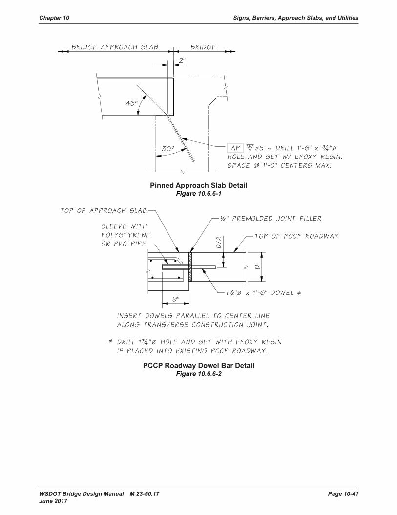
Chapter 10 Signs, Barriers, Approach Slabs, and Utilities
WSDOT Bridge Design Manual M 23-50.17 Page 10-41 June 2017
PinnedApproachSlabDetailFigure 10.6.6-1
PCCPRoadwayDowelBarDetailFigure 10.6.6-2
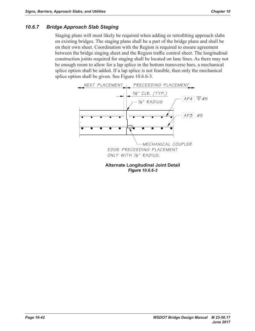
Signs, Barriers, Approach Slabs, and Utilities Chapter 10
Page 10-42 WSDOT Bridge Design Manual M 23-50.17 June 2017
10.6.7 Bridge Approach Slab StagingStagingplanswillmostlikelyberequiredwhenaddingorretrofittingapproachslabson existing bridges. The staging plans shall be a part of the bridge plans and shall be ontheirownsheet.CoordinationwiththeRegionisrequiredtoensureagreementbetweenthebridgestagingsheetandtheRegiontrafficcontrolsheet.Thelongitudinalconstructionjointsrequiredforstagingshallbelocatedonlanelines.Astheremaynotbeenoughroomtoallowforalapspliceinthebottomtransversebars,amechanicalspliceoptionshallbeadded.Ifalapspliceisnotfeasible,thenonlythemechanicalsplice option shall be given. See Figure 10.6.6-3.
AlternateLongitudinalJointDetailFigure 10.6.6-3
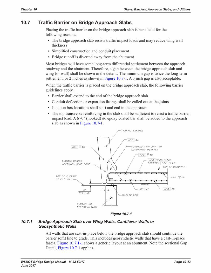
Chapter 10 Signs, Barriers, Approach Slabs, and Utilities
WSDOT Bridge Design Manual M 23-50.17 Page 10-43 June 2017
10.7 TrafficBarrieronBridgeApproachSlabsPlacingthetrafficbarrieronthebridgeapproachslabisbeneficialforthefollowing reasons.• Thebridgeapproachslabresiststrafficimpactloadsandmayreducewingwall
thickness• Simplifiedconstructionandconduitplacement• Bridgerunoffisdivertedawayfromtheabutment
Mostbridgeswillhavesomelong-termdifferentialsettlementbetweentheapproachroadwayandtheabutment.Therefore,agapbetweenthebridgeapproachslabandwing(orwall)shallbeshowninthedetails.Theminimumgapistwicethelong-termsettlement,or2inchesasshowninFigure 10.7-1. A 3 inch gap is also acceptable.
Whenthetrafficbarrierisplacedonthebridgeapproachslab,thefollowingbarrierguidelines apply.• Barrier shall extend to the end of the bridge approach slab• Conduitdeflectionorexpansionfittingsshallbecalledoutatthejoints• Junction box locations shall start and end in the approach• Thetoptransversereinforcingintheslabshallbesufficienttoresistatrafficbarrierimpactload.A6′-0″(hooked)#6epoxycoatedbarshallbeaddedtotheapproachslab as shown in Figure 10.7-1.
Figure 10.7-1
10.7.1 Bridge Approach Slab over Wing Walls, Cantilever Walls or Geosynthetic Walls
All walls that are cast-in-place below the bridge approach slab should continue the barriersoffitlinetograde.Thisincludesgeosyntheticwallsthathaveacast-in-placefascia. Figure 10.7.1-1showsagenericlayoutatanabutment.NotethesectionalGapDetail, Figure 10.7-1 applies.
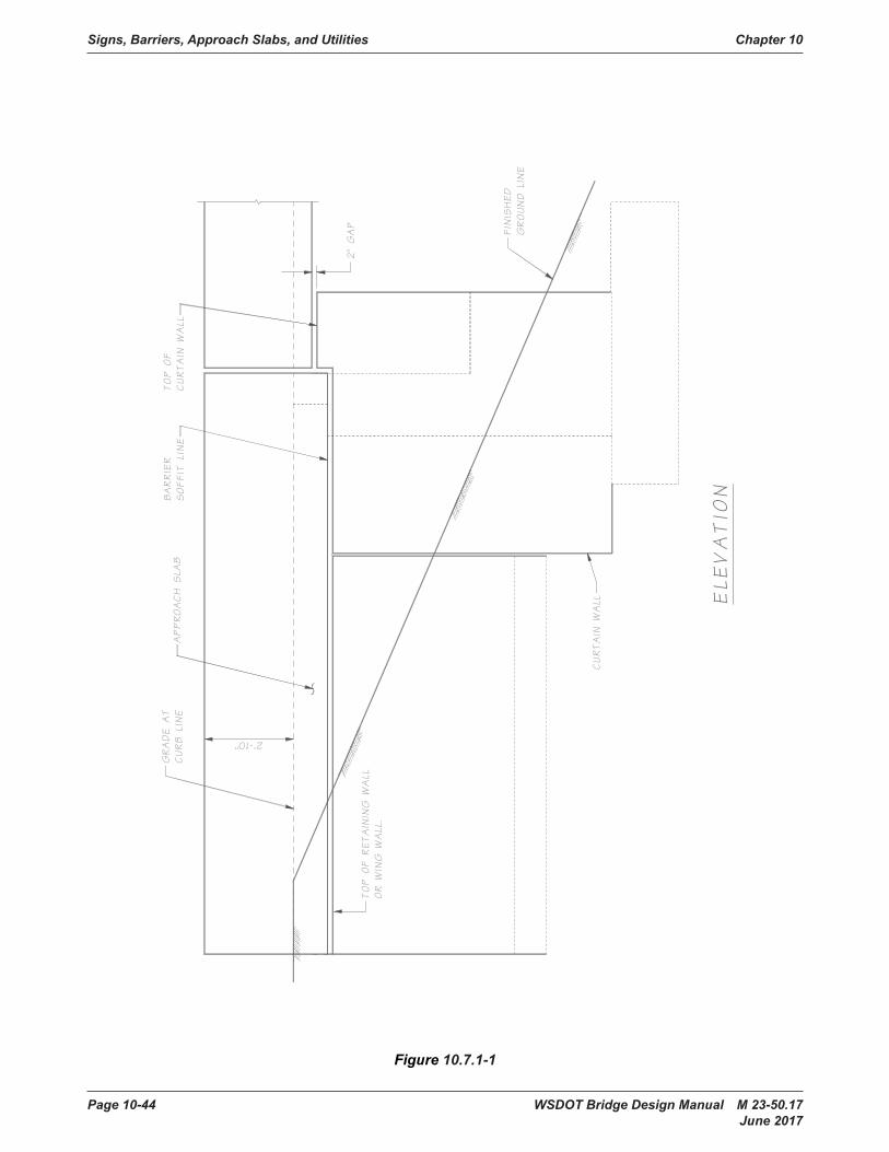
Signs, Barriers, Approach Slabs, and Utilities Chapter 10
Page 10-44 WSDOT Bridge Design Manual M 23-50.17 June 2017
Figure 10.7.1-1
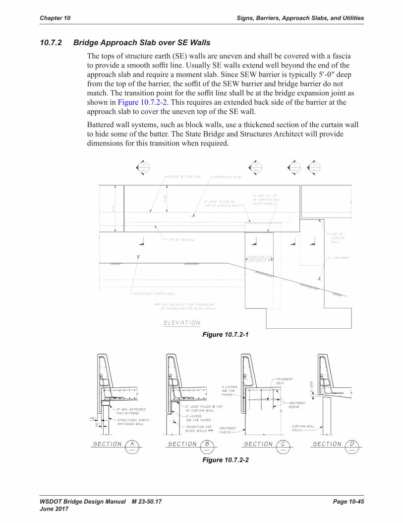
Chapter 10 Signs, Barriers, Approach Slabs, and Utilities
WSDOT Bridge Design Manual M 23-50.17 Page 10-45 June 2017
10.7.2 Bridge Approach Slab over SE WallsThetopsofstructureearth(SE)wallsareunevenandshallbecoveredwithafasciatoprovideasmoothsoffitline.UsuallySEwallsextendwellbeyondtheendoftheapproachslabandrequireamomentslab.SinceSEWbarrieristypically5′-0″deepfromthetopofthebarrier,thesoffitoftheSEWbarrierandbridgebarrierdonotmatch.Thetransitionpointforthesoffitlineshallbeatthebridgeexpansionjointasshown in Figure 10.7.2-2. This requires an extended back side of the barrier at the approach slab to cover the uneven top of the SE wall.
Batteredwallsystems,suchasblockwalls,useathickenedsectionofthecurtainwalltohidesomeofthebatter.TheStateBridgeandStructuresArchitectwillprovidedimensionsforthistransitionwhenrequired.
Figure 10.7.2-1
Figure 10.7.2-2

Signs, Barriers, Approach Slabs, and Utilities Chapter 10
Page 10-46 WSDOT Bridge Design Manual M 23-50.17 June 2017
10.8 UtilitiesInstalledwithNewConstruction10.8.1 General Concepts
The utilities included under this section are those described in Standard Specifications Section6-01.10.TheBridgedesignershalldetermineiftheutilitymaybeattachedtothestructureandthelocation.BridgeplansshallincludeallhardwarespecificationsanddetailsfortheutilityattachmentasprovidedinanywrittencorrespondencewiththeutilityandtheutilityagreementcoordinatedbytheWSDOTRegionUtilityEngineer with the associated utility.
Responsibilities of the Utility Company – TheRegionorutilitycompanywillinitiateutilityinstallationsandprovidedesigninformation.Theutilitycompanyshallbe responsible for calculating design stresses in the utility and design of the support system.UtilitysupportdesigncalculationswithaStateofWashingtonProfessionalEngineerstamp,signedanddated,shallbesubmittedtotheBridgeandStructuresOfficeforreview.ThefollowinginformationshallbeprovidedbytheutilitycompanyandshowninthefinalBridgePlans.• Locationoftheutilityoutsidethelimitsofthebridgestructure• Numberofutilities,type,size,andweight(orClass)ofutilitylines• Utilityminimumbendingradiusfortheconduitorpipelinespecified
Utility General Notes and Design Criteria are stated in Form224-047. See Figure 10.8.1-1.Thisformoutlinesmostofthegeneralinformationrequiredbytheutilitycompanytodesigntheirattachments.TheBridgeOfficewillgenerallyprovidethedesignforlightweighthangersystems,suchaselectricalconduits,attachedtonew structures.
Confined Spaces – Aconfinedspaceisanyplacehavingalimitedmeansofexitthatissubjecttotheaccumulationoftoxicorflammablecontaminantsoranoxygendeficientenvironment.Confinedspacesincludebutarenotlimitedtopontoons,boxgirder bridges, storage tanks, ventilation or exhaust ducts, utility vaults, tunnels, pipelines,andopen-toppedspacesmorethan4feetindepthsuchaspits,tubes,vaults,and vessels.
Coating and Corrosion Protection – Whenthebridgeistoreceivepigmentedsealer,considerationshallbegiventopaintinganyexposedutilitylinesandhangerstomatchthebridge.Whenapigmentedsealerisnotrequired,steelutilityconduitsandhangersshall be painted or galvanized for corrosion protection. The special provisions shall specify cleaning and painting procedures.

Chapter 10 Signs, Barriers, Approach Slabs, and Utilities
WSDOT Bridge Design Manual M 23-50.17 Page 10-47 June 2017
GeneralNotesandDesignCriteriaforUtilityInstallationstoExistingBridges WSDOTForm224-047
Figure 10.8.1-1
Permit/Franchise
Exhibit
Page of
" "
DOT Form 224-047 EFRevised 5/10
General Notes and Design Criteria forUtility Installations to Existing Bridges
General Notes
All materials and workmanship shall be in accordance with the requirements of the state ofWashington, Department of Transportation, Standard Specifications for Road, Bridge, andMunicipal Construction, current edition. The utility conduits shall be labeled in accordance withSection 6-01.10.
All steel in utility supports, including fastenings and anchorages, shall be galvanized in accordancewith AASHTO M-111 or M-232 (ASTM A-123 or A-153 respectively).
All utilities and utility support surfaces, including any galvanized utilities, shall be given a primercoat of state standard formula A-6-86 and two coats of state standard formula C-9-86. The finalcoat shall match the bridge color.
Galvanized metal or aluminum utilities completely hidden from public view may be exempted from the above painting requirements.
Any painted surfaces damaged during construction shall be cleaned and painted as noted above.
Any paint splatters shall be removed from the bridge.
Appearance of the utility installation shall be given serious consideration in all cases. Wherepossible, the utility installation shall be hidden from public view.
The notes and criteria explained here are presented as a guide only. Each proposed utilityinstallation shall be submitted to the Department of Transportation for approval on anindividual basis. Compliance with these criteria does not assure approval, nor doesvariance from these criteria, for reasonable cause, necessarily exclude approval.
Design Criteria
1. Pipelines carrying volatile fluids through a bridge superstructure shall be designed by theutility company in accordance with WAC 480-93, Gas Companies - Safety, and MinimumFederal Safety Standard, Title 49 Code of Federal Regulations (CFR) Section part 192. WAC468-34-210, Pipelines - Encasement, describes when casing is required for carrying volatilefluids across structures. Generally, casing is not required for pipelines conveying natural gasper the requirements of WAC 468-34-210. If casing is required, then WAC 468-34-210 andWAC 480-93-115 shall be followed.
2. Utilities shall not be attached above the bridge deck nor attached to railing or rail posts.
3. Utilities shall not extend below bottom of superstructure.
4. The utilities shall be provided with suitable expansion devices near bridge expansion jointsand/or other locations as required to prevent temperature and other longitudinal forces frombeing transferred to bridge members.
5. Rigid conduit shall extend 10 feet (3 meters) minimum, beyond the end of the bridgeabutment.
6. Utility supports shall be designed such that neither the conduit, the supports, nor the bridgemembers are overstressed by any loads imposed by the utility installation.
7. Utility locations and supports shall be designed so that a failure (rupture, etc.) will not result indamage to the bridge, the surrounding area, or be a hazard to traffic.
8. Conduit shall be rigid.
(Items 1 through 8 may be cross-referenced with Bridge Design Manual, Utilities Section.)
9. Lag screws may be used for attaching brackets to wooden structures. All bolt holes shall meetthe requirements of Sections 6-04.3(4) and 6-04.3(5) of the Washington State Department ofTransportation Standard Specifications for Road, Bridge, and Municipal Construction, currentedition.
10. Welding across main members will not be permitted. All welding must be approved.
11. Utilities shall be located to minimize bridge maintenance and bridge inspection problems.
12. Attach conduits or brackets to the concrete superstructure with resin bond anchors. Lagscrews shall not be used for attachment to concrete.
13. Drilling through reinforcing steel will not be permitted. If steel is hit when drilling, theanchorage location must be moved and the abandoned hole filled with nonshrink groutconforming to the requirements of Section 9-20.3(2) and placement shall be as required inSection 6-02.3(20) of the Washington State Department of Transportation StandardSpecifications for Road, Bridge, and Municipal Construction, current edition .
14. There shall be a minimum of 3 inches (80 millimeters) edge distance to the center line of boltholes in concrete.
15. All utilities and utility supports shall be designed not only to support their dead load but to resist other forces from the utility (surge, etc.) and wind and earthquake forces. The utility company may be asked to submit one set of calculations to verify their design forces.
16. Drilling into prestressed concrete members for utility attachments shall not be allowed.
17. Water or sewer lines to be placed lower than adjacent bridge footings shall be encased iffailure can cause undermining of the footing.
Permit/Franchise
Exhibit
Page of
" "
DOT Form 224-047 EFRevised 5/10

Signs, Barriers, Approach Slabs, and Utilities Chapter 10
Page 10-48 WSDOT Bridge Design Manual M 23-50.17 June 2017
GeneralNotesandDesignCriteriaforUtilityInstallationstoExistingBridges(continued) WSDOTForm224-047
Figure 10.8.1-1
Permit/Franchise
Exhibit
Page of
" "
DOT Form 224-047 EFRevised 5/10
General Notes and Design Criteria forUtility Installations to Existing Bridges
General Notes
All materials and workmanship shall be in accordance with the requirements of the state ofWashington, Department of Transportation, Standard Specifications for Road, Bridge, andMunicipal Construction, current edition. The utility conduits shall be labeled in accordance withSection 6-01.10.
All steel in utility supports, including fastenings and anchorages, shall be galvanized in accordancewith AASHTO M-111 or M-232 (ASTM A-123 or A-153 respectively).
All utilities and utility support surfaces, including any galvanized utilities, shall be given a primercoat of state standard formula A-6-86 and two coats of state standard formula C-9-86. The finalcoat shall match the bridge color.
Galvanized metal or aluminum utilities completely hidden from public view may be exempted fromthe above painting requirements.
Any painted surfaces damaged during construction shall be cleaned and painted as noted above.
Any paint splatters shall be removed from the bridge.
Appearance of the utility installation shall be given serious consideration in all cases. Wherepossible, the utility installation shall be hidden from public view.
The notes and criteria explained here are presented as a guide only. Each proposed utilityinstallation shall be submitted to the Department of Transportation for approval on anindividual basis. Compliance with these criteria does not assure approval, nor doesvariance from these criteria, for reasonable cause, necessarily exclude approval.
Design Criteria
1. Pipelines carrying volatile fluids through a bridge superstructure shall be designed by theutility company in accordance with WAC 480-93, Gas Companies - Safety, and MinimumFederal Safety Standard, Title 49 Code of Federal Regulations (CFR) Section part 192. WAC468-34-210, Pipelines - Encasement, describes when casing is required for carrying volatilefluids across structures. Generally, casing is not required for pipelines conveying natural gasper the requirements of WAC 468-34-210. If casing is required, then WAC 468-34-210 andWAC 480-93-115 shall be followed.
2. Utilities shall not be attached above the bridge deck nor attached to railing or rail posts.
3. Utilities shall not extend below bottom of superstructure.
4. The utilities shall be provided with suitable expansion devices near bridge expansion jointsand/or other locations as required to prevent temperature and other longitudinal forces frombeing transferred to bridge members.
5. Rigid conduit shall extend 10 feet (3 meters) minimum, beyond the end of the bridgeabutment.
6. Utility supports shall be designed such that neither the conduit, the supports, nor the bridgemembers are overstressed by any loads imposed by the utility installation.
7. Utility locations and supports shall be designed so that a failure (rupture, etc.) will not result indamage to the bridge, the surrounding area, or be a hazard to traffic.
8. Conduit shall be rigid.
(Items 1 through 8 may be cross-referenced with Bridge Design Manual, Utilities Section.)
9. Lag screws may be used for attaching brackets to wooden structures. All bolt holes shall meetthe requirements of Sections 6-04.3(4) and 6-04.3(5) of the Washington State Department ofTransportation Standard Specifications for Road, Bridge, and Municipal Construction, currentedition.
10. Welding across main members will not be permitted. All welding must be approved.
11. Utilities shall be located to minimize bridge maintenance and bridge inspection problems.
12. Attach conduits or brackets to the concrete superstructure with resin bond anchors. Lagscrews shall not be used for attachment to concrete.
13. Drilling through reinforcing steel will not be permitted. If steel is hit when drilling, theanchorage location must be moved and the abandoned hole filled with nonshrink groutconforming to the requirements of Section 9-20.3(2) and placement shall be as required inSection 6-02.3(20) of the Washington State Department of Transportation StandardSpecifications for Road, Bridge, and Municipal Construction, current edition .
14. There shall be a minimum of 3 inches (80 millimeters) edge distance to the center line of boltholes in concrete.
15. All utilities and utility supports shall be designed not only to support their dead load but to resist other forces from the utility (surge, etc.) and wind and earthquake forces. The utility company may be asked to submit one set of calculations to verify their design forces.
16. Drilling into prestressed concrete members for utility attachments shall not be allowed.
17. Water or sewer lines to be placed lower than adjacent bridge footings shall be encased iffailure can cause undermining of the footing.
Permit/Franchise
Exhibit
Page of
" "
DOT Form 224-047 EFRevised 5/10

Chapter 10 Signs, Barriers, Approach Slabs, and Utilities
WSDOT Bridge Design Manual M 23-50.17 Page 10-49 June 2017
10.8.2 Utility Design CriteriaAllutilitiesshallbedesignedtoresistStrengthandExtremeEventLimitsStates.Thisincludesandisnotlimitedtodeadload,expansion,surge,andearthquakeforces.Designers shall review WSDOT Form224-047 “General Notes and Design Criteria for Utility Installations to Existing Bridges”andtheitemsinthissectionwhendesigningautilitysystemorprovidingareviewforanexistingbridgeattachment.See Figure 10.8.1-1.
The Bridge Engineer shall review the utility design to ensure the utility support systemwillcarryalltransverseandverticalloading.Loadingwillinclude(andisnotlimitedto):deadload,temperatureexpansion,dynamicaction(waterhammer),andseismicinertialload.Positiveresistancetoloadsshallbeprovidedinalldirectionsperpendicular to and along the length of the utility as required by the utility engineer.
Wherepossible,dynamicfluidactionloadsshallberesistedoffofthebridge.Iftheseloadsmustberesistedonthebridge,theutilityengineershallbeinvolvedinthedesignofthesesupports.Theutilityengineershalldeterminethesedesignforces being applied to the bridge. Realize these forces can be generated in any pipe supportingmovingfluids,whichmayinclude,butarenotlimitedto:water,sewer,andstormwater.
Whereutilitiesareinsulated,theinsulationsystemshallbedesignedtoallowtheintendedmotionrangeofthehardwaresupportingtheutility.Thiswillpreventunanticipatedstressesfrombeingaddedtothehangerintheeventtheinsulationbindsup the hardware.
Utility Location – Utilities shall be located, such that a support failure will not result indamagetothebridge,thesurroundingarea,orbeahazardtotraffic.Inmostcases,the utility shall be installed between girders. Utilities and supports shall not extend belowthebottomofthesuperstructure.Utilitiesshallbeinstallednolowerthan1foot0inchesabovethebottomofthegirders.Insomecaseswhenappurtenancesarerequired(suchasairreleasevalves),careshallbetakentoprovideadequatespace.Theutilityinstallationshallbelocatedsoastominimizetheeffectontheappearanceofthe structure. Utilities shall not be attached above the bridge deck nor attached to the railings or posts.
Termination at the Bridge Ends – Utilityconduitandencasementsshallextend10feetminimumbeyondtheendsofthestructureinordertoreduceeffectsofembankmentsettlementontheutilityandprovideprotectionincaseoffutureworkinvolvingexcavationnearthestructure.Thisrequirementshallbeshownontheplans.Utilitiesoffthebridgemustbeinstalledpriortopavingofapproaches.Thisshouldbestated in the Special Provisions.
Utility Expansion – Theutilitiesshallbedesignedwithasuitableexpansionsystemasrequiredtopreventlongitudinalforcesfrombeingtransferredtobridgemembers.
Watermainsgenerallyremainaconstanttemperatureandareanchoredinthegroundattheabutments.However,thebridgewillmovewithtemperaturechangesandseismicforces.Pipesupportsystemsshallbedesignedtoallowforthebridgemovements.Forshortbridges,thisgenerallymeansthebridgewillmoveandtheutilitywillnotsinceitisanchoredattheabutments.Forlongbridgesthatrequirepipeexpansionjoints,designshallcarefullylocatepipeexpansionjointsandthecorrespondinglongitudinalload-carrying support.

Signs, Barriers, Approach Slabs, and Utilities Chapter 10
Page 10-50 WSDOT Bridge Design Manual M 23-50.17 June 2017
Electrical conduits that use PVC shall have an expansion device for every 100 foot of pipeduetothehighercoefficientofexpansion.Ifmorethantwojointsarespecified,acableorexpansionlimitingdeviceisrequiredtokeeptheendsfromseparating.
Utility Blockouts – Blockoutsshallbeprovidedinallstructuralmembersthatprohibitthepassageofutilities,suchasgirderenddiaphragms,piercrossbeams,andintermediatediaphragms.Theseblockoutsshallbelargeenoughtofitdeflectionfittings,andshallbeparalleltotheutility.Formultipleutilities,anoteshallbeaddedtotheplansthatthedeflectionfittingsshallbestaggeredsuchthatnofittingislocatedadjacenttoanother,ortheblockoutsshallbedesignedtofitbothfittings.Expansionfittingsshallbestaggered.
Gas Lines or Volatile Fluids–PipelinescarryingvolatilefluidsthroughabridgesuperstructureshallbedesignedbytheutilitycompanyinaccordancewithWAC 480-93,GasCompanies—Safety,andMinimumFederalSafetyStandard,Title 49 CodeofFederalRegulations(CFR)Sectionpart192.WAC 468-34-210, Pipelines—Encasement,describeswhencasingisrequiredforcarryingvolatilefluidsacrossstructures. Generally, casing is not required for pipelines conveying natural gas per the requirementsofWAC 468-34-210. If casing is required, then WAC 468-34-210 and WAC 480-93-115 shall be followed.
Water Lines – Transverse support or bracing shall be provided for all water lines to carryStrengthandExtremeEventLateralLoading.Firecontrolpipingisaspecialcasewhereunusualcaremustbetakentohandletheinertialloadsandassociateddeflections.TheUtilityEngineershallbeinvolvedinthedesignofsupportsresistingdynamicactionloadsanddeflections.
Inboxgirders(closedcell),aruptureofawaterlinewillgenerallyfloodacellbeforeemergencyresponsecanshutdownthewatermain.ThisshallbedesignedforasanExtremeEventIIloadcase,wheretheweightofwaterisadeadload(DC).AdditionalweepholesoropengratingshallbeconsideredtooffsetthisExtremeEvent(see Figure 10.8.3-1).Fulllengthcasingextending10-feetbeyondtheendofthebridge approach slab shall be considered as an alternate to additional weep holes or open grating.
Sewer Lines – Normally,anappropriateencasementpipeisrequiredforsewerlinesonbridges.Sewerlinesshallmeetthesamedesigncriteriaaswaterlines.SeetheutilityagreementortheHydraulicSectionfortypesofsewerpipematerialtypicallyused.
Electrical (Power and Communications) –Telephone,televisioncable,andpowerconduitshallbegalvanizedRigidMetalConduit(RGS)orRigidPolyvinylChlorideConduit(PVC).Wheresuchconduitisburiedinconcretecurbsorbarriersorhascontinuous support, such support is considered to be adequate. Where hangers or bracketssupportconduitatintervals,themaximumdistancebetweensupportsshallbe5 feet.

Chapter 10 Signs, Barriers, Approach Slabs, and Utilities
WSDOT Bridge Design Manual M 23-50.17 Page 10-51 June 2017
10.8.3 Box/Tub Girder BridgesUtilities shall not be placed inside reinforced concrete box girders less than 4 feet inside clear height and all precast prestressed concrete tub girders because reasonable access cannot be provided. Utilities shall be located between girders or under bridge decksoffitinthesecases.Inspectionlighting,accessandventilationshallalwaysbeprovided in girder cells containing utilities. Refer to the concrete and steel chapters for additional details.
Continuous Support and Concrete Pedestals–Specialutilities(suchaswaterorgasmains)inboxgirderbridgesshalluseconcretepedestals.Thisallowstheutilityto be placed, inspected, and tested before the deck is cast. Concrete pedestals consist ofconcretesupportsformedatsuitableintervalsandprovidedwithsometypeofclampingdevice.Continuoussupportsshallbeavoidedduetotheveryhighcostandadditional dead load to the structure.
ConcreteUtilitySupportsFigure 10.8.3-1
10.8.4 TrafficBarrierConduitAll new bridge construction shall install two 2-inch galvanized Rigid Metal Conduit (RGS)orRigidPolyvinylChlorideConduit(PVC)inthetrafficbarriers.TheseconduitsgenerallycarrywiringforTrafficSignals(TS)andLighting(LT).Otherwiringmaybeinstalledortheconduitmaybeusedforfutureapplications.PVCconduitmaybeusedonlyinstationary-formbarriers,andwillconnecttoRGSusingaPVCadaptorwhenexitingthebarrier.RGSconduitmaybeusedinstationary-formbarriers,butitshallbeusedinslipformbarriers.
Eachconduitshallbestubbed-outintoitsownconcretejunctionboxateachcornerofthebridge.TheBridgePlansmustshowtheplacementoftheconduitstoclearthestructure or any foreseeable obstructions.
Signs, Barriers, Approach Slabs, and Utilities Chapter 10
Page 10-52 WSDOT Bridge Design Manual M 23-50.17 June 2017
The galvanized steel conduit shall be wrapped with corrosion resistant tape at least one footinsideandoutsideoftheconcretestructure,andthisrequirementshallbesostatedon the plans. The corrosion resistant tape shall be 3M Scotch 50, Bishop 5, Nashua AVI10,orapprovedequal.Theusuallocationoftheconduitthroughouttheremainderofthebridgeshouldbeinthetrafficbarrier.
Pull boxes shall be provided within the barrier for each conduit at each end of the bridgeandatamaximumspacingof180feet.Forfiberopticsonly,spacingshallnotexceed360feet.ThepullboxsizeshallconformtothespecificationsoftheNationalElectricCodeorbeaminimumof8inchesby8inchesby18inchestofacilitatepullingofwires.Galvanizedsteelpullboxes(orjunctionsboxes)shallmeetthespecificationsofthe“NEMAType4X”standardforstationary-formbarrier,shallmeetthespecificationsofthe“NEMA3R”andbeadjustableindepthforslipformbarrier,andtheNEMAjunctionboxtypeshallbestatedontheplans.Stainlesssteelpullboxesmaybeusedasanoptiontothegalvanizedsteel.
In the case of existing bridges, an area 2 feet in width shall be reserved for conduit beginning at a point either 4 feet or 6 feet outside the face of usable shoulder. The fastening for and location of attaching the conduit to the existing bridge shall be workedoutonajob-by-jobbasis.
10.8.5 Conduit TypesAllelectricalconduitsshallbegalvanizedRigidMetalConduit(RGS)orRigidPolyvinylChlorideConduit(PVC).
Steel Pipe –Allpipeandfittingsshallbegalvanizedexceptforspecialuses.
PVC Pipe – PVCpipemaybeusedwithsuitableconsiderationsfordeflection,placementofexpansionfittings,andoffreezingwaterwithintheconduits.PVCpipeshallnotbeplacedinconcretetrafficbarrierswhentheslipformmethodisusedduetodamageandpipeseparationthatoftenoccursduringconcreteplacement.
10.8.6 Utility SupportsThe following types of supports are generally used for various utilities. Selection of a particular support type shall be based on the needs of the installation and the best economy.Allutilityinstallationsshalladdresstemperatureexpansioninthedesignofthesystemorexpansiondevices.
Utilitysupportsshallbedesignedsothatafailurewillnotresultindamagetothebridge,thesurroundingarea,orbeahazardtotraffic.Utilitysupportsshallbedesignedsothatanyloadsimposedbytheutilityinstallationdonotoverstresstheconduit,supports,bridgestructure,orbridgemembers.
Designsshallprovidelongitudinalandtransversesupportforloadsfromgravity,earthquakes,temperature,inertia,etc.Itisespeciallyimportanttoprovidetransverseandlongitudinalsupportforinsertsthatcannotresistmoment.
TheBridgeEngineershallrequestcalculationsfromtheutilitycompanyforanyattachmentdetailthatmaybequestionable.Utilityattachments,whichexertmomentsorlargeforcesatthesupports,shallbeaccompaniedbyatleastonesetofcalculationsfromtheutilitycompany.Bridgeattachmentsdesignedtoresistsurgeforcesshallalwaysbeaccompaniedbycalculations.

Chapter 10 Signs, Barriers, Approach Slabs, and Utilities
WSDOT Bridge Design Manual M 23-50.17 Page 10-53 June 2017
Concrete Embedment – This is the best structural support condition and offers maximum protection to the utility. Its cost may be high for larger conduit and the conduit cannot be replaced.
Pipe Hangers – Utility lines shall be suspended by means of cast-in-place inserts, whenever possible. This is the most common type of support for utilities to be hung under the bridge deck. This allows the use of standard cast-in-place inserts and is very flexible in terms of expansion requirements. For heavy pipes over traffic (10″ water main or larger), a Safety Factor of 1.5 should be used to resist vertical loads for Strength Design. This is to avoid complete failure of the utility hanger system by failure of one hanger. Vertical inserts will not provide resistance to longitudinal forces. Longitudinal and transverse supports shall be provided for ITS conduits. Vertical supports shall be spaced at 5 foot maximum intervals for telephone and power conduits, and at a spacing to resist design loads for all other utilities.
When 3/4″ or 7/8″ diameter hanger rods are suspended from cast-in-place inserts, at least three of the following inserts shall be identified: Cooper B-Line B22-I Series, Unistrut 3200 Series, Powerstrut 349 Series, Halfen HT5506 or similar. The specific cast-in-place insert within each series shall be identified based on the required length of insert. The cast-in-place insert shall be at least 6″ long and hot dipped galvanized in accordance with AASHTO M 111 or AASHTO M 232.
The insert shall not interfere with reinforcement in the bridge deck. The inserts shall be installed level longitudinally and transversely. When the superelevation of the roadway is not significant, a single, long insert may be used to support multiple hanger rods. When the superelevation becomes significant, a single insert may be used for each hanger.
Occasionally large diameter utilities require pipe rolls that only fit on 1″ diameter hanger rods. When 1″ diameter hanger rods are required, the Anvil Fig. 286 and Unistrut P3246 insert shall be used. The designer shall only specify this insert when absolutely necessary.
The Bridge Engineer shall verify that the cast-in-place insert has sufficient capacity to support the loads from the hanger rod.
Transverse supports may be provided by a second hanger extending from a girder or by a brace against the girder. The Bridge Standard Drawing 10.8-A1-1 and 10.8-A1-2 depict typical utility support installations and placement at abutments and diaphragms. Transverse supports shall, at a minimum, be located at every other vertical support.

Signs, Barriers, Approach Slabs, and Utilities Chapter 10
Page 10-54 WSDOT Bridge Design Manual M 23-50.17 June 2017
10.9 UtilityReviewProcedureforInstallationonExistingBridgesIt is the responsibility of the Region Utilities Engineer to forward any proposed attachmentstoexistingbridgestotheBridgePreservationOffice.TheBridgePreservationOfficeisresponsibleforreviewingonlythosedetailspertainingtothebridgecrossingsuchasattachmentdetailsortrenchingdetailsadjacenttobridgepiersorabutments.
TheBridgePreservationOfficereviewsproposedutilityattachmentsandeitherapprovestheattachmentorreturnsforcorrection(RFC).AcurrentfileformostutilityattachmentsismaintainedintheBridgePreservationOffice.Theturnaroundtimeforreviewing the proposals should not exceed four weeks.
TheRegiondeterminesthenumberofcopiestobereturned.MostRegionssendfivecopiesoftheproposedutilityattachment.Iftheproposalisapproved,BridgePreservationwillfileonecopyintheutilityfileandreturnfourmarkedcopies.Ifithasbeenreturnedforcorrectionornotapproved,onecopyisplacedintheutilityfileandtwomarkedcopiesarereturned,thrutheRegion,totheutility.SeeSection10.9.1,“Utility Review Checklist.”
Utilityattachments,whichexertmomentsorlargeforcesatthesupports,shallbeaccompaniedbyatleastonesetofcalculationsfromtheutilitycompany.Bridgeattachmentsdesignedtoresistsurgeforcesshallalwaysbeaccompaniedbycalculations. The connection details shall be designed to successfully transfer all forces tothebridgewithoutcausingoverstressintheconnectionsortothebridgemembersto which they are attached. For large utilities, the bridge itself shall have adequate capacitytocarrytheutilitywithoutaffectingtheliveloadcapacity.
Theengineermayrequestcalculationsfromtheutilitycompanyforanyattachmentdetailthatmaybequestionable.Allplans,details,andcalculationsshallbestamped,signed, and dated by a Professional Engineer licensed in the State of Washington. Additionally,forheavierutilities,suchaswaterlinesorsewerlines,theengineermayrequestaloadratingofthestructure,whichshallbestamped,signed,anddatedbyalicensed professional engineer in the state of Washington to follow the guidelines of Chapter 13. The ratings shall be based solely on the engineer of record calculations.
Guidelines for Utility Companies
DetailingguidelinesforutilitycompaniestofollowwhendesigningutilityattachmentsarelistedinWSDOTForm224-047,“General Notes and Design Criteria for Utility Installations to Existing Bridges.” See Figure 10.8.1-1. See Section 10.8 for other requirements,whichinclude,butarenotlimitedto:designofutility,materialused,andspacing of supports.
Water lines and sewer lines installed within box girders shall have full length casing extending 10-feet beyond the end of the bridge approach slab. The casing shall be sufficienttopreventthefloodingofacelluponautilitylinerupture.
Chapter 10 Signs, Barriers, Approach Slabs, and Utilities
WSDOT Bridge Design Manual M 23-50.17 Page 10-55 June 2017
Guidelines for Column Attachments
Thefollowingguidelinesshallbefollowedforinstallingattachmentstocolumns.• Attachmentsonroundcolumnsmaybeeitherdrilledandboltedorbanded.• Attachmentsonnon-circularcolumnshapesshallbedrilledandbolted.• Onlypercussiondrillingmethodsshallbeallowedonbridgecolumns,andonlyforsmalldiameterresinbondedanchorinstallation(0.50″diametermax.).Drillingwillnormallyresultinblindholes,andtheseholesshallbepatchedwithmaterialconformingtoStandard SpecificationsSection6-02.3(20).
• Drillingintoprestressedorpost-tensionedconcreteelementsisnotpermitted.SomeWSDOTbridgesutilizeprestressedcolumns.
Any proposed conduit installation on a WSDOT bridge structure shall be reviewed andapprovedbytheRiskReductionEngineerintheBridgePreservationOffice.Iftheconduit installation originates via a change order, then the Headquarters Construction Officemayprovideapproval,andshallinformtheRiskReductionEngineerofthe decision.
10.9.1 Utility Review ChecklistThischecklistappliestoallproposedutilityattachmentstoexistingbridges.
1. Completecursorychecktobecomefamiliarwiththeproposal.
2. Determinelocationofexistingutilities.
a. Check Bridge Inspection Report for any existing utilities.
b. CheckBridgePreservation’sutilityfileforanyexistingutilitypermitsorfranchises and possible as-built plans.
c. Anyexistingutilitiesonthesamesideofthestructureastheproposedutilityshall be shown on the proposal.
3. Reviewthefollowingwithallcommentsinred:
a. Layoutthatincludesdimension,directions,SRnumberandbridgenumber.
b. Adequate spacing of supports.
c. Adequatestrengthofsupportsasattachedtothebridge(calculationsmaybenecessary).
d. Maximumdesignpressureandregularoperatingpressureforpressurepipesystems.
e. Adequatelateralbracingandthrustprotectionforpressurepipesystems.
f. Doestheutilityobstructmaintenanceoraccessibilitytokeybridgecomponents?
g. Checklocation(elevationandplanview)oftheutilitywithrespecttopierfootingsorabutments.Iftrenchlimitsencroachwithinthe45°envelopefromthe footing edge, consult the Materials Lab.
h. Forcemainsorwaterflowsystemsmayrequireencasementiftheyareinexcavationsbelowthebottomofafooting.
Signs, Barriers, Approach Slabs, and Utilities Chapter 10
Page 10-56 WSDOT Bridge Design Manual M 23-50.17 June 2017
4. WritealetterofreplyoremailtotheRegionsoacopywillbereturnedtoyouindicating the package has been accepted and sent out.
5. Stampanddatetheplansusingthesamedateasshownontheletterofreplyoremail.
6. Createafilefolderwiththefollowinginformation:
a. Bridgeno.,name,utilitycompanyorutilitytype,andfranchiseorpermitnumber.
b. One set of approved plans and possibly one or two pages of the original designplansifnecessaryforquickfuturereference.Previoustransmittalsand plans not approved or returned to correction should be discarded to avoid unnecessaryclutterofthefiles.
c. Includetheletterofsubmittalandacopyoftheletterofreplyoremailafterit has been accepted.
7. GivethecompletepackagetotheDesignUnitManagerforreviewandplacethefolderintheutilityfileafterthereview.

Chapter 10 Signs, Barriers, Approach Slabs, and Utilities
WSDOT Bridge Design Manual M 23-50.17 Page 10-57 June 2017
10.10 DrilledAnchorsForPermanentAttachmentsWSDOTallowsconventionaldrilledanchorssystems(resinbondedanchorsandundercutanchors)forpermanentattachmentsinmanyaspectsofbridgedesign,includingthepermanentcyclicalorsustainedtensionapplicationslistedbelow.• Signstructuresmountedtothesidesofbridgeswithamaximumcantileverlength
or total span of 10 feet.• Lightstandardswithamaximumcantileverlengthof16feet.• Signstructureswithasupporting,roundorrectangular,postorbeamwithamaximumdimensionof8inches.
• Retrofittedcorbelsforbridgeapproachslabs.• Supporting utilities under bridges, including water pipes, electrical conduit and otherutilitypipingsystems.
Forresinbondedanchorsusedinpermanentsustainedtensionapplications,theadhesiveanchorsystemsshallhavesuccessfullycompletedtestingforlongtermsustainedloadperformanceinaccordancewithACI 355.4.Dependingonthespecificapplicationofthepermanentattachment,additionalqualityassuranceperformancemeasuressuchasfieldprooftestingofproductionanchorsinaccordancewithACI 355.4 should be included in the design. Resin bonded anchors shall not be usedinmonotubesignstructure,signstructuretruss,andmastarmtypesignalstandard applications.
Fastsetresinbondingmaterialsshallnotbeusedforresinbondedanchors.
For carbon steel undercut anchors, hot-dipgalvanizedcomponentsarepreferred,butnotcurrentlyavailablefromsuppliers.Undercutanchorswithelectroplatedzinccoatings are not considered equivalent or better and shall not be used. Therefore, stainlesssteelundercutanchorsarethepreferredoption.Dependingonthespecificapplicationofthepermanentattachment,additionalqualityassuranceperformancemeasuressuchasfieldprooftestingofproductionanchorsinaccordancewithACI355.2 should be included in the design.
The design procedure for adhesive and undercut anchors shall be in accordance with ACI 318 Chapter 17,andsystemqualificationtestingrequirements in accordance with ACI 355.4 and ACI 355.2, respectively.
Expansionanchorsandmechanicalanchorsarenotallowedforanypermanentapplications,exceptforspecificconnectiondetailspreviouslyapprovedbytheBridgeandStructuresOfficeforprecastconcretepanelfacedstructuralearthwallsaslowrisk applications.
Cast-in-placeconcreteanchorsremainthepreferredoptionforbridgeapplications.
Signs, Barriers, Approach Slabs, and Utilities Chapter 10
Page 10-58 WSDOT Bridge Design Manual M 23-50.17 June 2017
10.11 Drainage DesignEven though it is rare that poor drainage is directly responsible for a structural failure, itstillmustbeaprimaryconsiderationinthedesign.Poordrainagecancauseproblemssuchaspondingontheroadway,erosionofabutments,anddeteriorationofstructuralmembers.Collectingtherunoffandtransportingitawayfromthebridgecanpreventmostoftheproblems.Propergeometricsduringthepreliminarystageisessentialinordertoaccomplishthis.TheHydraulicsBranchrecommendsplacingthebridgedeckdrainageoffofthestructure.Therefore,theBridgeDesignSectionhasadoptedthepolicythatallexpansionjointsshallbewatertight.
Geometrics
Bridgesshallhavesufficienttransverseandlongitudinalslopestoallowthewatertorunquicklytothedrains.Atransverseslopeof.02′/ftandlongitudinalslopeof0.5percentforminimumvalvesarerequired.Avoidplacingsagverticalcurvesandsuperelevation crossovers on the structure that could result in hydroplaning conditions or,incoldclimates,sheetsoficefrommeltingsnow.Theuseofunsymmetricalverticalcurvesmayassistthedesignerinshiftingthelowpointoffthestructure.
Hydrology
Hydrologicalcalculationsaremadeusingtherationalequation.A10-yearstormeventwitha5-minutedurationistheintensityusedforallinletsexceptforsagverticalcurveswherea50-yearstormintensityisrequired.
On Bridge Systems
Drainsshallonlybeplacedonbridgestructureswhenrequired.Ifrequired,thefirstpreferenceistoplace5-inchdiameterpipedrainsthathavenobarsanddropstraighttotheground.Atothertimes,suchasforsteelstructures,thestraightdropdrainisunacceptableandapipingsystemwithbridgedrainsisrequired.Theminimumpipediametershallbe6incheswithnosharpbendswithinthesystem.TheHydraulicsBranchshallbecontactedtodeterminethetypeofdrainrequired(preferablyNeenah).
Construction
BridgedeckshaveastriatedfinishinaccordancewiththeStandard Specifications Section6-02.3(10)D5,however,theguttershaveanuntexturedfinish(steeltrowel)foradistanceof2feetfromthecurb.Thisuntexturedareaprovidesforsmoothgutterflowand a Manning n value of .015 in the design.
Chapter 10 Signs, Barriers, Approach Slabs, and Utilities
WSDOT Bridge Design Manual M 23-50.17 Page 10-59 June 2017
10.12 BridgeSecurity10.12.1 General
Securitybasedbridgedesignanditsdirectcorrelationtomodernsocialissuesisaddressedinthissection.Criminalactivity,illegalencampments,graffiti,hindrancetoeconomicdevelopmentandpubliceyesorecreateunwantedexpensive.Theyalsopose public health concerns and safety hazards for State Maintenance and Operations practices. The issue exists in urban areas as well as rural and recreational locales.
Bridgesaredominantstructuresinlandscapes.Theyareheldtoahigherstandardofdesignduetotheirinfluenceoncommunities,whereeconomicandsocialsettingsareaffectedbytheirquality.Initialprojectcostsavingsmayquicklybeovershadowedbyincreasedexternalizedcosts.TheseexternalizedcostsarebornbylocalmunicipalitiesandbusinessesaswellasotherdepartmentswithinWSDOT.
WSDOT bridge inspectors are required to inspect all bridges at least once every 24months.Thepresenceoftheillegalencampments,aswellasgarbage,hypodermicneedles,andfecesoftenmakesitimpossibletodoaclose,hands-oninspectionoftheabutmentsandbearingsofbridges.TheBridgePreservationOfficehasrequestedthatmaintenancecleanuptransientcampswhenitbecomesdifficultorimpossibletodoanadequateinspectionofthebridges.Campfiressetbythehomelesshavealsocauseddamagetobridges.
BridgeMaintenanceCrewsalsofacethesamedifficultywhentheyneedtodorepairworkonbridgesintheurbanarea.Cleanuprequires(perlaw)postingthebridgeseventy-two hours prior to any work. Material picked up is tagged, bagged, and stored forretrieval.Oftentheoffendersarebackthenextday.
10.12.2 DesignDesignisdeterminedonacasebycasebasisusingtwostrategies.Thesestrategiesareuniversallyacceptedbestpractices.Thefirst,CrimePreventionthroughEnvironmentalDesign(CEPTD),isamulti-disciplinaryapproachtodeterringcriminalbehavior.
Thesecond,ContextSensitiveDesign(CSS),isalsomulti-disciplinaryandfocusesonprojectdevelopmentmethods.Multi-disciplinaryteamsconsistofengineersandarchitectsbutmayincludelawenforcement,localbusinesses,socialserviceproviders,and psychologists.
A. CPTEDprincipalsarebaseduponthetheorythattheproperdesignandeffectiveuseofthebuiltenvironmentcanreducecrime,reducethefearofcrime,andimprovethequalityoflife.BuiltenvironmentimplementationsofCPTEDseektodissuadeoffendersfromcommittingcrimesbymanipulatingthebuiltenvironmentinwhichthosecrimesproceedfromoroccur.Thesixmainconceptsareterritoriality,surveillance,accesscontrol,image/maintenance,activitysupportandtargethardening.Applyingallofthesestrategiesiskeywhenpreventingcrimein any neighborhood or right-of-way.
Naturalsurveillanceandaccesscontrolstrategieslimittheopportunityforcrime.Territorialreinforcementpromotessocialcontrolthroughavarietyofmeasures.Thesemayincludeenhancedaestheticsorpublicart.Image/maintenanceandactivitysupportprovidethecommunitywithreassuranceandtheabilitytostop
Signs, Barriers, Approach Slabs, and Utilities Chapter 10
Page 10-60 WSDOT Bridge Design Manual M 23-50.17 June 2017
crimebythemselves.Targethardeningstrategiesmayinvolvefencingorconcreteenclosuresortheymayincludealltechniquestoresolvecrimeorchronictrespassintoonefinalstep.
B. WSDOTimplementsFHWA’sCSSdesigndevelopmentprinciplesthroughExecutiveOrderE1028.TheCSSmethodsrequiredesignerstoconsiderthephysical,economic,andsocialsettingofaproject.Stakeholder’sinterestsaretobeaccounted for; including area residents and business owners.
10.12.3 Design CriteriaNewbridgesneedtoaddressdesignfortheenvironmentbybasiccriteria:• Slopes under bridges need to be steep; around a 1:1 slope, and hardened with somethinglikesolidconcretesothatflatareascannotbecarvedintothehillside.Flat areas under bridge superstructures attract inappropriate uses and should beomitted.
• Illegalurbancampershavebeenknowntobuildsheltersbetweentheconcretegirders.Abutmentwallsneedtobehighenoughthattheydenyaccesstothesuperstructureelements.Whenitisnotfeasibletodesignfordeterrencethesites need to be hardened with fencing buried several feet into the soil or with solid concrete walls. See Figures 14.2.3a and 14.2.3b for high security fence and concretewallexamples.
• Regularchainlinkiseasycut,thereforestoutermaterialneedstobespecified.• Landscape design should coordinate with region or headquarters landscape architects.Areasneedtobevisibletolawenforcement.
‘Highsecurity’proprietaryfencedesignsmaybeemployed,oruniquecase-by-casecustomdesignsmayberequired.Whererequired,coordinatewiththeStateBridgeandStructures Architect.
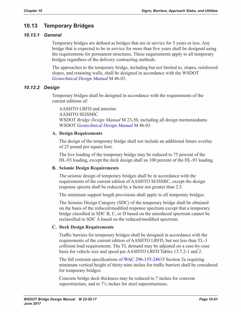
Chapter 10 Signs, Barriers, Approach Slabs, and Utilities
WSDOT Bridge Design Manual M 23-50.17 Page 10-61 June 2017
10.13 TemporaryBridges10.13.1 General
Temporarybridgesaredefinedasbridgesthatareinservicefor5yearsorless.Anybridgethatisexpectedtobeinserviceformorethanfiveyearsshallbedesignedusingtherequirementsforpermanentstructures.Theserequirementsapplytoalltemporarybridgesregardlessofthedeliverycontractingmethods.
Theapproachestothetemporarybridge,includingbutnotlimitedto,slopes,reinforcedslopes, and retaining walls, shall be designed in accordance with the WSDOT Geotechnical Design Manual M 46-03.
10.13.2 DesignTemporarybridgesshallbedesignedinaccordancewiththerequirementsofthecurrent editions of:
AASHTOLRFDandinterims AASHTO SEISMIC WSDOT Bridge Design ManualM23-50,includingalldesignmemorandums WSDOT Geotechnical Design Manual M 46-03
A. Design Requirements
Thedesignofthetemporarybridgeshallnotincludeanadditionalfutureoverlayof 25 pound per square foot.
Theliveloadingofthetemporarybridgemaybereducedto75percentofthe HL-93 loading, except the deck design shall us 100 percent of the HL-93 loading.
B. Seismic Design Requirements
TheseismicdesignoftemporarybridgesshallbeinaccordancewiththerequirementsofthecurrenteditionofAASHTOSEISMIC,exceptthedesignresponse spectra shall be reduced by a factor not greater than 2.5.
Theminimumsupportlengthprovisionsshallapplytoalltemporarybridges.
TheSeismicDesignCategory(SDC)ofthetemporarybridgeshallbeobtainedonthebasisofthereduced/modifiedresponsespectrumexceptthatatemporarybridgeclassifiedinSDCB,C,orDbasedontheunreducedspectrumcannotbereclassifiedtoSDCAbasedonthereduced/modifiedspectrum.
C. Deck Design Requirements
TrafficbarriersfortemporarybridgesshallbedesignedinaccordancewiththerequirementsofthecurrenteditionofAASHTOLRFD,butnotlessthanTL-3collisionloadrequirements.TheTLdemandmaybeadjustedonacase-by-casebasis for vehicle size and speed per AASHTO LRFD Tables 13.7.2-1 and 2.
ThefallrestraintspecificationsofWAC 296-155-24615 Section 2a requiring minimumverticalheightofthirty-nineinchesfortrafficbarriersshallbeconsideredfortemporarybridges.
Concretebridgedeckthicknessmaybereducedto7inchesforconcretesuperstructure,andto7½inchesforsteelsuperstructures.

Signs, Barriers, Approach Slabs, and Utilities Chapter 10
Page 10-62 WSDOT Bridge Design Manual M 23-50.17 June 2017
Epoxycoatingrequirementforbridgedeckreinforcementmaybewaivedfortemporarybridgeswith2inchmincoverforthetopmatofreinforcement.
Thedrivingsurfaceofthetemporarybridgeshallbedurable,skidresistantdeck,withaninitialskidnumberofatleast35andmaintainingaskidnumberof26minimum,inaccordancewithAASHTO T 242.TheContractorshallmaintainthetemporarybridge,includingthedrivingsurface,forthelifeofthetemporarybridgeintheproject.
D. Superstructure Design Requirements
A3inchminimumHMAoverlaycouldbeusedfortemporarybridgesmadeofadjacentprecastconcretemembers.
Steeltemporarybridgesneednotbepainted.
Fatigueneednotbecheckedfortemporarybridgeswithsteelsuperstructure.
Allwelding,repairwelding,andweldinginspection,ofsteelcomponentsofthetemporarybridgeshallconformtotheStandard SpecificationsSection6-03.3(25)and6-03.3(25)Arequirementsspecifiedforsteelbridges.
Allowabletensilestressforprecast-prestressedconcretegirdersunderservicelimitstateloadcombinationsperAASHTOLRFDArticle5.9.4.2.2maybeusedinlieuofthosespecifiedinSection5.2.1C.
E. Foundation Design Requirements
Piletypessuchasprecast,prestressedconcretepiles,steelHpiles,timberpiles,micropilesandsteelpipepilesmaybeusedfortemporarybridges.
Soldierpilewallwithtreatedtimberlaggingmaybeusedfortemporarybridges.
10.13.3 NBIRequirementsTemporaryorre-commissionedbridgesusedasadetourandin-servicelongerthe90days shall receive full NBIS (all SI&A data; ex., NBIS inspection, load ratings and scourevaluation).AllSI&AdatashallbesubmittedtotheWashingtonStateNBIdatabasewithin90daysofopeningtovehicletraffic.An“open”bridgeisdefinedasabridgethatisnearsubstantialcompletionwithgeneralhighwaytrafficaccessing/operatingonthebridgeinaconfigurationthatisthefinalplannedconfiguration.
Phasedconstructionstages,ifcarryingtrafficfor90daysorlongershallfallintothesecriteria.
Bridges open less than 90 days will need regular “safety” type inspections to ensure the safeoperationoftrafficonthebridge.
Contracts are to clearly identify the owner and who is responsible for all of this NBIS criteria.
Loadratingsforlegaltrucksandspecialhaulingvehiclesarerequiredfortemporaryandbridgesconstructedinphasedstages.Theminimumratingfactorshallnotbelessthan 1.0.
10.13.4 SubmittalRequirementsTheContractorshallsubmitdrawingsandcopiesofsupportingdesigncalculationsofthetemporarybridgetotheEngineerforapprovalinaccordancewithStandard

Chapter 10 Signs, Barriers, Approach Slabs, and Utilities
WSDOT Bridge Design Manual M 23-50.17 Page 10-63 June 2017
SpecificationsSection6-01.9.Thesubmittalshallincludeanerectionplanandprocedure in accordance with Standard SpecificationsSection6-03.3(7)A.
Submittalsfortemporarybridgeswithtotallengthofmorethan200ftshallbestampedandsignedbyaWashingtonStateregisteredStructuralEngineer(SE)inaccordancewiththerequirementsofWAC 196-23.
TheContractorshallconstructthetemporarybridgeinaccordancewiththeworkingdrawingsanderectionplanasapprovedbytheEngineer,environmentalpermitconditionsspecifiedinSection1-07.5assupplementedintheSpecialProvisionsandas shown in the Plans, and in accordance with the details shown in the Plans.
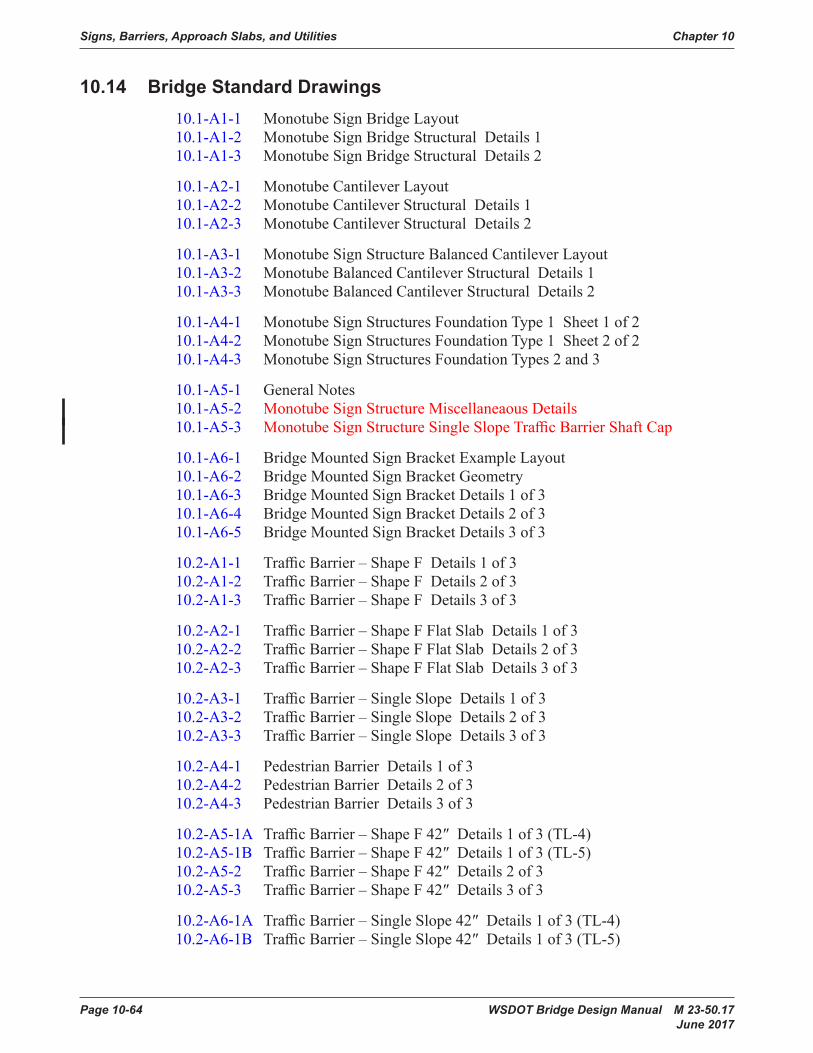
Signs, Barriers, Approach Slabs, and Utilities Chapter 10
Page 10-64 WSDOT Bridge Design Manual M 23-50.17 June 2017
10.14 BridgeStandardDrawings10.1-A1-1 Monotube Sign Bridge Layout 10.1-A1-2 Monotube Sign Bridge Structural Details 1 10.1-A1-3 Monotube Sign Bridge Structural Details 2
10.1-A2-1 Monotube Cantilever Layout 10.1-A2-2 Monotube Cantilever Structural Details 1 10.1-A2-3 Monotube Cantilever Structural Details 2
10.1-A3-1 Monotube Sign Structure Balanced Cantilever Layout 10.1-A3-2 Monotube Balanced Cantilever Structural Details 1 10.1-A3-3 Monotube Balanced Cantilever Structural Details 2
10.1-A4-1 Monotube Sign Structures Foundation Type 1 Sheet 1 of 2 10.1-A4-2 Monotube Sign Structures Foundation Type 1 Sheet 2 of 2 10.1-A4-3 Monotube Sign Structures Foundation Types 2 and 3
10.1-A5-1 General Notes 10.1-A5-2 Monotube Sign Structure Miscellaneaous Details 10.1-A5-3 MonotubeSignStructureSingleSlopeTrafficBarrierShaftCap
10.1-A6-1 BridgeMountedSignBracketExampleLayout 10.1-A6-2 BridgeMountedSignBracketGeometry 10.1-A6-3 Bridge Mounted Sign Bracket Details 1 of 3 10.1-A6-4 Bridge Mounted Sign Bracket Details 2 of 3 10.1-A6-5 Bridge Mounted Sign Bracket Details 3 of 3
10.2-A1-1 TrafficBarrier–ShapeF Details1of3 10.2-A1-2 TrafficBarrier–ShapeF Details2of3 10.2-A1-3 TrafficBarrier–ShapeF Details3of3
10.2-A2-1 TrafficBarrier–ShapeFFlatSlab Details1of3 10.2-A2-2 TrafficBarrier–ShapeFFlatSlab Details2of3 10.2-A2-3 TrafficBarrier–ShapeFFlatSlab Details3of3
10.2-A3-1 TrafficBarrier–SingleSlope Details1of3 10.2-A3-2 TrafficBarrier–SingleSlope Details2of3 10.2-A3-3 TrafficBarrier–SingleSlope Details3of3
10.2-A4-1 Pedestrian Barrier Details 1 of 3 10.2-A4-2 Pedestrian Barrier Details 2 of 3 10.2-A4-3 Pedestrian Barrier Details 3 of 3
10.2-A5-1A TrafficBarrier–ShapeF42″ Details1of3(TL-4) 10.2-A5-1B TrafficBarrier–ShapeF42″ Details1of3(TL-5) 10.2-A5-2 TrafficBarrier–ShapeF42″ Details2of3 10.2-A5-3 TrafficBarrier–ShapeF42″ Details3of3
10.2-A6-1A TrafficBarrier–SingleSlope42″ Details1of3(TL-4) 10.2-A6-1B TrafficBarrier–SingleSlope42″ Details1of3(TL-5)

Chapter 10 Signs, Barriers, Approach Slabs, and Utilities
WSDOT Bridge Design Manual M 23-50.17 Page 10-65 June 2017
10.2-A6-2 TrafficBarrier–SingleSlope42″ Details2of3 10.2-A6-3 TrafficBarrier–SingleSlope42″ Details3of3(TL-4andTL-5)
10.2-A7-1 TrafficBarrier–ShapeFLuminaireAnchorageDetails 10.2-A7-2 TrafficBarrier–SingleSlopeLuminaireAnchorageDetails 10.2-A7-3 PedestrainBarrierLuminaireAnchorageDetails
10.4-A1-1 ThrieBeamRetrofitConcreteBaluster 10.4-A1-2 ThrieBeamRetrofitConcreteRailbase 10.4-A1-3 ThrieBeamRetrofitConcreteCurb 10.4-A1-4 WPThrieBeamRetrofitSL1 Details1of2 10.4-A1-5 WPThrieBeamRetrofitSL1 Details2of2
10.4-A2-1 TrafficBarrier–ShapeFRehabilitation Details1of3 10.4-A2-2 TrafficBarrier–ShapeFRehabilitation Details2of3 10.4-A2-3 TrafficBarrier–ShapeFRehabilitation Details3of3
10.5-A1-1 Bridge Railing Type Pedestrian Details 1 of 2 10.5-A1-2 Bridge Railing Type Pedestrian Details 2 of 2
10.5-A2-1 Bridge Railing Type BP Details 1 of 2 10.5-A2-2 Bridge Railing Type BP Details 2 of 2
10.5-A3-1 Bridge Railing Type S-BP Details 1 of 2 10.5-A3-2 Bridge Railing Type S-BP Details 2 of 2
10.5-A4-1 Pedestrian Railing Details 1 of 2 10.5-A4-2 Pedestrian Railing Details 2 of 2
10.5-A5-1 Bridge Railing Type Chain Link Snow Fence 10.5-A5-2 Bridge Railing Type Snow Fence Details 1 of 2 10.5-A5-3 Bridge Railing Type Snow Fence Details 2 of 2 10.5-A5-4 Bridge Railing Type Chain Link Fence
10.6-A1-1 Bridge Approach Slab Details 1 of 3 10.6-A1-2 Bridge Approach Slab Details 2 of 3 10.6-A1-3 Bridge Approach Slab Details 3 of 3
10.6-A2-1 PavementSeatRepairDetails 10.6-A2-2 PavementSeatRepairDetails
10.8-A1-1 Utility Hanger Details 10.8-A1-2 Utility Hanger Details
10.11-A1-1 BridgeDrainModification 10.11-A1-2 BridgeDrainModificationforTypes2thru5

Signs, Barriers, Approach Slabs, and Utilities Chapter 10
Page 10-66 WSDOT Bridge Design Manual M 23-50.17 June 2017
10.15 ReferencesAASHTOGuideSpecificationforLRFD Seismic Bridge Design, 2ndEdition(2011),Washington DC.
AASHTO, 1st Edition(2015),WashingtonDC.
AASHTO Standard Specifications for Highway Bridges, 17th Edition(2002),Washington DC.
ACI318-14(2014)“BuildingCodeRequirementsforStructuralConcreteandCommentary,”AmericanConcreteInstitute,FarmingtonHills,MI.
ACI355.2-07(2007)“QualificationofPost-InstalledMechanicalAnchorsinConcreteandCommentary,”AmericanConcreteInstitute,FarmingtonHills,MI.
ACI355.4-11(2014)“QualificationofPost-InstalledAdhesiveAnchorsinConcreteandCommentary,”AmericanConcreteInstitute,FarmingtonHills,MI.
NCHRPReport230,“RecommendedProceduresfortheSafetyPerformanceEvaluation of Highway Appurtenances”, Transportation Research Board, 1991, Washington DC.
NCHRPReport350,“RecommendedProceduresfortheSafetyPerformanceEvaluation of Highway Features”, Transportation Research Board, 1993, Washington DC.
NCHRPReport663,“DesignofRoadsideBarrierSystemsPlacedonMSERetainingWalls”,NCHRPProject22-20,TransportationResearchBoard,2010,WashingtonDC.
WSDOT Design Manual M 22-01
WSDOT Geotechnical Design Manual M 46-03
WSDOT Standard Plans M 21-01
WSDOT Standard Specifications for Road, Bridge, and Municipal Construction (Standard Specifications) M 41-10
WSDOT E 1028 Context Sensitive Solutions Executive Order
Newman,O.DefensibleSpace:CrimePreventionThroughUrbanDesign.NewYork:Macmillan.1972.
Jacobs,Jane.TheDeathandLifeofGreatAmericanCities.NewYork:RandomHouse.1961.