chapter 10 signs, barriers, approach slabs, and utilities ... · wsdot bridge design manual m...
TRANSCRIPT

WSDOT Bridge Design Manual M 23-50.18 Page 10-i June 2018
Chapter 10 Signs, Barriers, Approach Slabs, and Utilities Contents
10.1 Sign and Luminaire Supports . . . . . . . . . . . . . . . . . . . . . . . . . . . . . . . . . . . . . . . . . . 10-110.1.1 Loads . . . . . . . . . . . . . . . . . . . . . . . . . . . . . . . . . . . . . . . . . . . . . . . . . . . . . . . 10-110.1.2 Bridge Mounted Signs . . . . . . . . . . . . . . . . . . . . . . . . . . . . . . . . . . . . . . . . . . . . 10-310.1.3 Monotube Sign Structures Mounted on Bridges . . . . . . . . . . . . . . . . . . . . . . . . . . 10-710.1.4 Monotube Sign Structures . . . . . . . . . . . . . . . . . . . . . . . . . . . . . . . . . . . . . . . . . 10-810.1.5 Foundations . . . . . . . . . . . . . . . . . . . . . . . . . . . . . . . . . . . . . . . . . . . . . . . . . . 10-1210.1.6 Truss Sign Bridges: Foundation Sheet Design Guidelines . . . . . . . . . . . . . . . . . . 10-15
10.2 BridgeTrafficBarriers . . . . . . . . . . . . . . . . . . . . . . . . . . . . . . . . . . . . . . . . . . . . . . . 10-1610.2.1 General Guidelines . . . . . . . . . . . . . . . . . . . . . . . . . . . . . . . . . . . . . . . . . . . . . 10-1610.2.2 Bridge Railing Test Levels . . . . . . . . . . . . . . . . . . . . . . . . . . . . . . . . . . . . . . . . 10-1610.2.3 Available WSDOT Designs . . . . . . . . . . . . . . . . . . . . . . . . . . . . . . . . . . . . . . . 10-1710.2.4 Design Criteria . . . . . . . . . . . . . . . . . . . . . . . . . . . . . . . . . . . . . . . . . . . . . . . . 10-20
10.3 AtGradeConcreteBarriers . . . . . . . . . . . . . . . . . . . . . . . . . . . . . . . . . . . . . . . . . . 10-2510.3.1 Differential Grade Concrete Barriers . . . . . . . . . . . . . . . . . . . . . . . . . . . . . . . . 10-2510.3.2 Traffic Barrier Moment Slab . . . . . . . . . . . . . . . . . . . . . . . . . . . . . . . . . . . . . . 10-2610.3.3 Precast Concrete Barrier . . . . . . . . . . . . . . . . . . . . . . . . . . . . . . . . . . . . . . . . . 10-29
10.4 BridgeTrafficBarrierRehabilitation . . . . . . . . . . . . . . . . . . . . . . . . . . . . . . . . . . . 10-3010.4.1 Policy . . . . . . . . . . . . . . . . . . . . . . . . . . . . . . . . . . . . . . . . . . . . . . . . . . . . . . 10-3010.4.2 Guidelines . . . . . . . . . . . . . . . . . . . . . . . . . . . . . . . . . . . . . . . . . . . . . . . . . . . 10-3010.4.3 Design Criteria . . . . . . . . . . . . . . . . . . . . . . . . . . . . . . . . . . . . . . . . . . . . . . . . 10-3010.4.4 WSDOT Bridge Inventory of Bridge Rails . . . . . . . . . . . . . . . . . . . . . . . . . . . . 10-3110.4.5 Available Retrofit Designs . . . . . . . . . . . . . . . . . . . . . . . . . . . . . . . . . . . . . . . . 10-3110.4.6 Available Replacement Designs . . . . . . . . . . . . . . . . . . . . . . . . . . . . . . . . . . . . 10-32
10.5 BridgeRailing . . . . . . . . . . . . . . . . . . . . . . . . . . . . . . . . . . . . . . . . . . . . . . . . . . . . . 10-3310.5.1 Design . . . . . . . . . . . . . . . . . . . . . . . . . . . . . . . . . . . . . . . . . . . . . . . . . . . . . . 10-3310.5.2 Railing Types . . . . . . . . . . . . . . . . . . . . . . . . . . . . . . . . . . . . . . . . . . . . . . . . . 10-33
10.6 BridgeApproachSlabs . . . . . . . . . . . . . . . . . . . . . . . . . . . . . . . . . . . . . . . . . . . . . . 10-3510.6.1 Notes to Region for Preliminary Plan . . . . . . . . . . . . . . . . . . . . . . . . . . . . . . . . 10-3510.6.2 Bridge Approach Slab Design Criteria . . . . . . . . . . . . . . . . . . . . . . . . . . . . . . . 10-3610.6.3 Bridge Approach Slab Detailing . . . . . . . . . . . . . . . . . . . . . . . . . . . . . . . . . . . . 10-3610.6.4 Skewed Bridge Approach Slabs . . . . . . . . . . . . . . . . . . . . . . . . . . . . . . . . . . . . 10-3710.6.5 Approach Anchors and Expansion Joints . . . . . . . . . . . . . . . . . . . . . . . . . . . . . . 10-3810.6.6 Bridge Approach Slab Addition or Retrofit to Existing Bridges . . . . . . . . . . . . . . 10-3910.6.7 Bridge Approach Slab Staging . . . . . . . . . . . . . . . . . . . . . . . . . . . . . . . . . . . . . 10-40

Chapter 10 Signs, Barriers, Approach Slabs, and Utilities
Page 10-ii WSDOT Bridge Design Manual M 23-50.18 June 2018
10.7 TrafficBarrieronBridgeApproachSlabs . . . . . . . . . . . . . . . . . . . . . . . . . . . . . . . 10-4110.7.1 Bridge Approach Slab over Wing Walls, Cantilever Walls or Geosynthetic Walls . 10-4110.7.2 Bridge Approach Slab over SE Walls . . . . . . . . . . . . . . . . . . . . . . . . . . . . . . . . 10-43
10.8 UtilitiesInstallationonNewandExistingStructures . . . . . . . . . . . . . . . . . . . . . . 10-4410.8.1 General Concepts . . . . . . . . . . . . . . . . . . . . . . . . . . . . . . . . . . . . . . . . . . . . . . 10-4410.8.2 Utility Design Criteria . . . . . . . . . . . . . . . . . . . . . . . . . . . . . . . . . . . . . . . . . . . 10-4710.8.3 Box/Tub Girder Bridges . . . . . . . . . . . . . . . . . . . . . . . . . . . . . . . . . . . . . . . . . 10-4910.8.4 Traffic Barrier Conduit . . . . . . . . . . . . . . . . . . . . . . . . . . . . . . . . . . . . . . . . . . 10-4910.8.5 Conduit Types . . . . . . . . . . . . . . . . . . . . . . . . . . . . . . . . . . . . . . . . . . . . . . . . 10-5010.8.6 Utility Supports . . . . . . . . . . . . . . . . . . . . . . . . . . . . . . . . . . . . . . . . . . . . . . . 10-50
10.9 ReviewProcedureforUtilityInstallationsonExistingStructures . . . . . . . . . . . 10-5210.9.1 Utility Review Checklist . . . . . . . . . . . . . . . . . . . . . . . . . . . . . . . . . . . . . . . . . 10-53
10.10 AnchorsforPermanentAttachments . . . . . . . . . . . . . . . . . . . . . . . . . . . . . . . . . . 10-55
10.11 Drainage Design . . . . . . . . . . . . . . . . . . . . . . . . . . . . . . . . . . . . . . . . . . . . . . . . . . . 10-56
10.12 BridgeSecurity . . . . . . . . . . . . . . . . . . . . . . . . . . . . . . . . . . . . . . . . . . . . . . . . . . . . 10-5710.12.1 General . . . . . . . . . . . . . . . . . . . . . . . . . . . . . . . . . . . . . . . . . . . . . . . . . . . . . 10-5710.12.2 Design . . . . . . . . . . . . . . . . . . . . . . . . . . . . . . . . . . . . . . . . . . . . . . . . . . . . . . 10-5710.12.3 Design Criteria . . . . . . . . . . . . . . . . . . . . . . . . . . . . . . . . . . . . . . . . . . . . . . . . 10-58
10.13 TemporaryBridges . . . . . . . . . . . . . . . . . . . . . . . . . . . . . . . . . . . . . . . . . . . . . . . . . 10-5910.13.1 General . . . . . . . . . . . . . . . . . . . . . . . . . . . . . . . . . . . . . . . . . . . . . . . . . . . . . 10-5910.13.2 Design . . . . . . . . . . . . . . . . . . . . . . . . . . . . . . . . . . . . . . . . . . . . . . . . . . . . . . 10-5910.13.3 NBI Requirements . . . . . . . . . . . . . . . . . . . . . . . . . . . . . . . . . . . . . . . . . . . . . 10-6110.13.4 Submittal Requirements . . . . . . . . . . . . . . . . . . . . . . . . . . . . . . . . . . . . . . . . . 10-61
10.14 BridgeStandardDrawings . . . . . . . . . . . . . . . . . . . . . . . . . . . . . . . . . . . . . . . . . . . 10-62
10.99 References . . . . . . . . . . . . . . . . . . . . . . . . . . . . . . . . . . . . . . . . . . . . . . . . . . . . . . . . 10-65

WSDOT Bridge Design Manual M 23-50.18 Page 10-1 June 2018
Signs, Barriers, Chapter 10 Approach Slabs, and Utilities
10.1 Sign and Luminaire Supports10.1.1 Loads
A. General
ThereferenceusedindevelopingthefollowingofficecriteriaistheAASHTOLRFDStandard Specifications for Structural Supports for Highway Signs, Luminaires, and Traffic Signals, First Edition dated 2015 (including latest interims), and shall be the basis for analysis and design.
B. Dead Loads
Sign: (Including panel and wind beams; does not include vert. bracing) 3.25 lbs/ft2 Luminaire (effective projected area of head = 3.3 sq ft) 60 lbs/each Fluorescent Lighting 3.0 lbs/ft StandardSignalHead 60lbs/each Mercury Vapor Lighting 6.0 lbs/each Sign Brackets Calc. Structural Members Calc. 5 foot wide maintenance walkway: (Including mounting brackets and handrail) 160 lbs/ft SignalHeadw/3lenses: (Effective projected area with backing plate = 9.2 sq ft) 60 lbs/each
C. Live Load
A live load consisting of a single load of 500 lb distributed over 2.0 feet transversely to the member shall be used for designing members for walkways and platforms. The load shall be applied at the most critical location where a worker or equipment could beplaced,seeAASHTO2015,Section3.6.
D. Wind Loads
A3secondgustwindspeedshallbeusedintheAASHTOwindpressureequation.The3secondwindgustmapinAASHTOisbasedonthewindmapinANSI/ASCE 7-16.
Basic wind speed of 115 mph shall be used in computing design wind pressure using equation3.8.1-1ofAASHTOSection3.8.1.Thisisbasedonthehighriskcategorywith a mean recurrence interval of1700yearsperAASHTOTable3.8-1.
TheAlternateMethodofWindPressuresgiveninAppendixCoftheAASHTO2015 Specificationsshallnotbeused.

Chapter 10 Signs, Barriers, Approach Slabs, and Utilities
Page 10-2 WSDOT Bridge Design Manual M 23-50.18 June 2018
E. Fatigue Design
FatiguedesignshallconformtoAASHTOSection11withtheexceptionofsquare and rectangulartubeshape.AASHTOdoesnotprovidefatiguecalculationsforshapes with less than 8 sides. Therefore, calculating the Constant Amplitude Fatigue Threshold, DT(Table11.9.3.1-2,AASHTO2015)wastakentobethelargerouterflattoflatdistanceoftherectangulartube.FatigueCategoriesarelistedinTable11.6-1.Overhead Cantilever and Bridge Sign and signal structures, high-mast lighting towers (HMLT),poles,andbridgemountedsignbracketsshallconformtothefollowingfatigue categories.
Fatigue Category I: Overhead cantilever sign structures (maximum span of 35 feet and no VMS installation), overhead sign bridge structures, high-mast lighting towers 55 feet or taller in height, bridge-mounted sign brackets, and all signal bridges. Gantry or pole structures used to support sensitive electronic equipment (tolling, weigh-in-motion, transmitter/receiver antennas, transponders, etc.) shall bedesignedforFatigueCategoryI,andshallalsomeetanydeflectionlimitationsimposed by the electronic equipment manufacturers.
Fatigue Category II: For structures not explicitly falling into Category I or III.
Fatigue Category III: Lighting poles 50 feet or less in height with rectangular or square cross sections, or non-tapered round cross sections, and overhead cantilevertrafficsignals(maximumcantileverlength65feet).
Signbridges,cantileversignstructures,signalbridges,andoverheadcantilevertrafficsignals mounted on bridges shall be either attached to substructure elements (e.g., crossbeam extensions) or to the bridge superstructure at pier locations. Mounting these features to bridges as described above will help to avoid resonance concerns between the bridge structure and the signing or signal structure.
CCTVcamerapoleshallmeetdeflectioncriteriaspecifiedonStandardPlanJ-29-15forfixedbase.
The “XYZ” limitation shown in Table 10.1.4-2 shall be met for Monotube Cantilevers. The “XYZ” limitation consists of the product of the sign area (XY) and the arm from the centerline of the posts to the centerline of the sign (Z). See Appendix 10.1-A2-1 for details.
F. Ice and Snow Loads
A 3 psf ice load may be applied around all the surfaces of structural supports, horizontal members, and luminaires, but applied to only one face of sign panels (Section3.7,AASHTO2015).
Walk-through VMS shall not be installed in areas where appreciable snow loads may accumulate on top of the sign, unless positive steps are taken to prevent snow build-up.
G. Group Load Combinations
Sign, luminaire, and signal support structures are designed using the load factors from Table3.4-1,AASHTO2015(includinglatestinterims).

Signs, Barriers, Approach Slabs, and Utilities Chapter 10
WSDOT Bridge Design Manual M 23-50.18 Page 10-3 June 2018
10.1.2 Bridge Mounted SignsA. Vertical Clearance
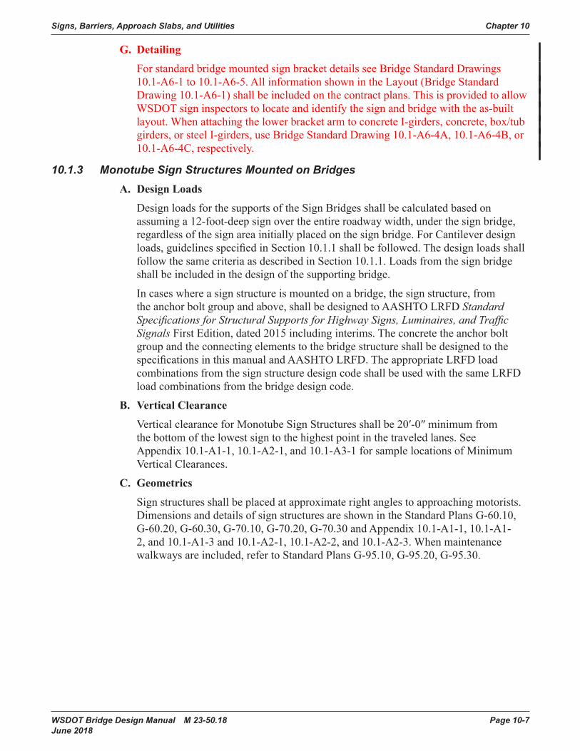
All new signs mounted on bridge structures shall be positioned such that the bottom of the sign or lighting bracket does not extend below the bottom of the bridge as shown in Figure 10.1.2-1. The position of the sign does not need to allow for the future placement of lights below the sign. If lights are to be added in the future they will be mounted above the sign. To ensure that the bottom of the sign or lighting bracket is above the bottom of the bridge, the designer shall maintain at least a nominal 2 inch dimension between the bottom of the sign or lighting and the bottom of the bridge to account for construction tolerances and bracket arm sag.
Bridge mounted sign brackets shall be designed to account for the weight of added lights, and for the wind effects on the lights to ensure bracket adequacy if lighting is attached in the future.
Figure 10.1.2-1 Sign Vertical Clearance

Chapter 10 Signs, Barriers, Approach Slabs, and Utilities
Page 10-4 WSDOT Bridge Design Manual M 23-50.18 June 2018
B. Geometrics
1. Signs shall be installed at approximate right angles to approaching motorists. For structures above a tangent section of roadway, signs shall be designed to provide a sign skew within 5° from perpendicular to the lower roadway (see Figure 10.1.2-2).
Figure 10.1.2-2 Sign Skew on Tangent Roadway
2. For structures located on or just beyond a horizontal curve of the lower roadway, signs shall be designed to provide a sign chord skew within 5° from perpendicular to the chord-point determined by the approach speed (see Figure 10.1.2-3).
Figure 10.1.2-3 Sign Skew on Curved Roadway

Signs, Barriers, Approach Slabs, and Utilities Chapter 10
WSDOT Bridge Design Manual M 23-50.18 Page 10-5 June 2018
3. The top of the sign shall be level. Maximum sign height shall be decided by the Region. If the structure is too high above the roadway, then the sign shall not be placed on the structure (see Figure 10.1.2-4).
Figure 10.1.2-4
C. Aesthetics
1. The support structure shall not extend beyond the limits of the sign unless the extension is unavoidable.
2. The sign support shall be detailed in such a manner that will permit the sign and lighting bracket to be installed level.
3. When the sign support will be exposed to view, special consideration is required in determining member sizes and connections to provide as pleasing an appearance as possible.
D. Sign Placement
1. Signs shall not be placed under bridge overhangs. This causes partial shading or partial exposure to the elements and problems in lifting the material into position and making the required connections. Signs shall never be placed directly under the drip-line of the structure. These conditions may result in uneven fading, discoloring,anddifficultyinreading.
2. A minimum of 2 inches of clearance shall be provided between back side of the sign support and edge of the bridge. See Figure 10.1.2-5.

Chapter 10 Signs, Barriers, Approach Slabs, and Utilities
Page 10-6 WSDOT Bridge Design Manual M 23-50.18 June 2018
Figure 10.1.2-5 Sign Horizontal Location
3. VMS units shall not be installed on bridges were practical and require approval of
the WSDOT Bridge Design Engineer when installed on bridges with a skew.
E. Installation
1. Adhesive anchors or cast-in-place ASTM F593 Type 304, Group 1 Condition CW, anchor rods shall be used to install the sign brackets on the structure. Size andminimuminstallationdepthshallbegivenintheplansorspecifications.The adhesive anchors shall be installed normal to the concrete surface. Adhesive anchorsshallnotbeplacedthroughthewebsorflangesofprestressedorpost-tensioned girders unless approved by the WSDOT Bridge Design Engineer. Adhesive anchors shall not be used at overhead locations other than with horizontal hole/anchor alignment.
2. Bridge mounted sign structures shall not be placed on bridges with steel superstructures unless approved by the WSDOT Bridge Design Engineer.
F. Installing/Replacing New Sign on Existing Bracket Supports
When installing a new sign on existing bracket supports, the following shall be required:
1. All hardware shall be replaced per the current Standard Specifications.
2. The new sign area shall not exceed the original designed sign area.
3. The inspection report for the bracket shall be reviewed to ensure that the supports are in good condition. If there is not an inspection report, then an inspection shall be performed on the bracket.
Signs, Barriers, Approach Slabs, and Utilities Chapter 10
WSDOT Bridge Design Manual M 23-50.18 Page 10-7 June 2018
G. Detailing
For standard bridge mounted sign bracket details see Bridge Standard Drawings 10.1-A6-1 to 10.1-A6-5. All information shown in the Layout (Bridge Standard Drawing 10.1-A6-1) shall be included on the contract plans. This is provided to allow WSDOT sign inspectors to locate and identify the sign and bridge with the as-built layout. When attaching the lower bracket arm to concrete I-girders, concrete, box/tub girders, or steel I-girders, use Bridge Standard Drawing 10.1-A6-4A, 10.1-A6-4B, or 10.1-A6-4C, respectively.
10.1.3 Monotube Sign Structures Mounted on BridgesA. Design Loads
Design loads for the supports of the Sign Bridges shall be calculated based on assuming a 12-foot-deep sign over the entire roadway width, under the sign bridge, regardless of the sign area initially placed on the sign bridge. For Cantilever design loads,guidelinesspecifiedinSection10.1.1shallbefollowed.Thedesignloadsshallfollow the same criteria as described in Section 10.1.1. Loads from the sign bridge shall be included in the design of the supporting bridge.
In cases where a sign structure is mounted on a bridge, the sign structure, from theanchorboltgroupandabove,shallbedesignedtoAASHTOLRFDStandard Specifications for Structural Supports for Highway Signs, Luminaires, and Traffic Signals First Edition, dated 2015 including interims. The concrete the anchor bolt group and the connecting elements to the bridge structure shall be designed to the specificationsinthismanualandAASHTOLRFD.TheappropriateLRFDloadcombinations from the sign structure design code shall be used with the same LRFD load combinations from the bridge design code.
B. Vertical Clearance
VerticalclearanceforMonotubeSignStructuresshallbe20′-0″minimumfromthe bottom of the lowest sign to the highest point in the traveled lanes. See Appendix 10.1-A1-1, 10.1-A2-1, and 10.1-A3-1 for sample locations of Minimum Vertical Clearances.
C. Geometrics
Sign structures shall be placed at approximate right angles to approaching motorists. Dimensions and details of sign structures are shown in the Standard Plans G-60.10, G-60.20, G-60.30, G-70.10, G-70.20, G-70.30 and Appendix 10.1-A1-1, 10.1-A1-2, and 10.1-A1-3 and 10.1-A2-1, 10.1-A2-2, and 10.1-A2-3. When maintenance walkways are included, refer to Standard Plans G-95.10, G-95.20, G-95.30.

Chapter 10 Signs, Barriers, Approach Slabs, and Utilities
Page 10-8 WSDOT Bridge Design Manual M 23-50.18 June 2018
10.1.4 Monotube Sign StructuresA. Sign Bridge Conventional Design
Table 10.1.4-1 provides the conventional structural design information to be used for a Sign Bridge Layout, Bridge Standard Drawing 10.1-A1-1; along with the Structural Detail sheets, which are Bridge Standard Drawing 10.1-A1-2 and Bridge Standard Drawing 10.1-A1-3; General Notes, Bridge Standard Drawing 10.1-A5-1; and Miscellaneous Details, Bridge Standard Drawing 10.1-A5-2.
B. Cantilever Conventional Design
Table 10.1.4-2 provides the conventional structural design information to be used for a Cantilever Layout, Bridge Standard Drawing 10.1-A2-1; along with the Structural Detail sheets, which are Bridge Standard Drawing 10.1-A2-2 and Bridge Standard Drawing 10.1-A2-3; General Notes, Bridge Standard Drawing 10.1-A5-1; and Miscellaneous Details, Bridge Standard Drawing 10.1-A5-2.

Signs, Barriers, Approach Slabs, and Utilities Chapter 10
WSDOT Bridge Design Manual M 23-50.18 Page 10-9 June 2018
Table 10.1.4-1 Standard Monotube Sign BridgesSPAN
LENGTH POSTS ¦ BEAM A ¦ BEAM B ¦ BEAM C ¦ BEAM D ¦ CAMBER"S" "H" "A" "B" "T1" "L1" "B" "C" "T2" "L2" "B" "C" "T2" "L3" "B" "C" "T2"
LESS THAN 60'-0"
30'-0" OR
LESS1'-6" 2'-0" ½" 6'-0" 2'-0" 2'-0" ½" 0'-0" 2'-0" 2'-0" ½"
13'-0" TO
48'-0"2'-0" 2'-0" ½" - - - - 2¾"
60'-0" TO
75'-0"
30'-0" OR
LESS1'-6" 2'-3" ⅝" 6'-0" 2'-3" 2'-0" ⅝"
9'-0" TO
14'-0"2'-3" 2'-0" ⅝"
30'-0" TO
35'-0"2'-3" 2'-0" ⅝" - - - - 3¾"
+75'-0" TO
90'-0"
30'-0" OR
LESS1'-6" 2'-3" ⅝" 6'-0" 2'-3" 2'-0" ⅝"
14'-0" TO
19'-0"2'-3" 2'-0" ⅝"
35'-0" TO
40'-0"2'-3" 2'-0" ⅝" - - - - 5"
+90'-0" TO
105'-0"
30'-0" OR
LESS1'-9" 2'-6" ⅝" 6'-0" 2'-6" 2'-3" ⅝"
19'-0" TO
26'-6"2'-6" 2'-3" ⅝" 40'-0" 2'-6" 2'-3" ⅝" - - - - 6"
+105'-0" TO
120'-0"
30'-0" OR
LESS1'-9" 2'-6" ⅝" 6'-0" 2'-6" 2'-3" ⅝"
26'-6" TO
34'-0"2'-6" 2'-3" ⅝" 40'-0" 2'-6" 2'-3" ⅝" - - - - 7½"
+120'-0" TO
135'-0"
30'-0" OR
LESS2'-0" 2'-6" ⅝" 6'-0" 2'-6" 2'-6" ⅝"
34'-0" TO
41'-6"2'-6" 2'-6" ⅝" 40'-0" 2'-6" 2'-6" ⅝" - - - - 8½"
+135'-0" TO
150'-0"
30'-0" OR
LESS2'-0" 2'-6" ⅝" 6'-0" 2'-6" 2'-6" ⅝"
41'-6" TO
49'-0"2'-6" 2'-6" ⅝" 40'-0" 2'-6" 2'-6" ⅝" - - - - 10½"
+150'-0" TO
165'-0"
30'-0" OR
LESS2'-0" 2'-8" ¾" 6'-0" 2'-8" 2'-8" ⅝" 27'-0" 2'-8" 2'-8" ⅝"
18'-5" TO
25'-6"2'-8" 2'-8" ⅝" 48'-
0" 2'-8" 2'-8" ⅝" 13¾"
+165'-0" TO
180'-0"
30'-0" OR
LESS2'-0" 2'-8" ¾" 6'-0" 2'-8" 2'-8" ⅝" 30'0" 2'-8" 2'-8" ⅝"
22'-6" TO
30'-0"2'-8" 2'-8" ⅝" 48'-
0" 2'-8" 2'-8" ⅝" 15¾"
SPAN LENGTH POST BASE ¦
BOLTED SPLICE #1 L1 TO L2 AND L1 TO L3
BOLTED SPLICE #2 L2 TO L3
BOLTED SPLICE #3 L3 TO L4
MAX SIGN AREA"S" "D1" "S5" "S6" "T3" "T6" "S1" "S2" "S3" "S4" "T4" "T5" "S1" "S2" "S3" "S4" "T4" "T5" "S1" "S2" "S3" "S4" "T4" "T5"
LESS THAN 60'-0"
1½" 4 4 3" ¾" 5 - 5 - 2" ⅝" - - - - - - - - - - - - 600 SQ . FT .
60'-0" TO
75'-0"1¾" 4 4 3" ¾" 6 - 5 - 2" ⅝" 6 - 5 - 2¼" ¾" - - - - - - 700
SQ FT .
+75'-0" TO
90'-0"1¾" 4 4 3" ¾" 6 - 5 - 2" ⅝" 6 - 5 - 2¼" ¾" - - - - - - 800 SQ .
FT .
+90'-0" TO
105'-0"1¾" 4 5 3" 1" 7 - 6 - 2" ⅝" 7 5 6 4 2½" 1" - - - - - - 900 SQ .
FT .
+105'-0" TO
120'-0"1¾" 4 5 3" 1" 7 - 6 - 2" ⅝" 7 5 6 4 2½" 1" - - - - - - 900 SQ .
FT .
+120'-0" TO
135'-0"2" 4 5 3" 1" 7 5 7 5 2" ⅝" 7 5 7 5 2½" 1" - - - - - - 900 SQ .
FT .
+135'-0" TO
150'-0"2" 4 5 3" 1" 7 5 7 5 2" ⅝" 7 5 7 5 2½" 1" - - - - - - 900 SQ .
FT .
+150'-0" TO
180'-0"2" 4 5 3" 1" 7 5 7 5 2" ⅝" 7 5 7 5 2½" 1" 7 5 7 5 2½" 1" 900 SQ .
FT .
¦ NOTE: DENOTES MAIN LOAD CARRYING TENSILE MEMBERS OR TENSION COMPONENTS OF FLEXURAL MEMBERS .

Chapter 10 Signs, Barriers, Approach Slabs, and Utilities
Page 10-10 WSDOT Bridge Design Manual M 23-50.18 June 2018
Table 10.1.4-2 Standard Monotube CantileversSpan Length Posts ¦ Beam A ¦ Beam B ¦
Camber"S" "H" "A" "B" "T1" "L1" "B" "C" "T2" "L2" "B" "C" "T2"Less Than
20'-0"30'-0"
or Less 1'-6" 2'-0" ½" 6'-0" 2'-0" 2'-0" ½" 14'-0" 2'-0" 2'-0" ½" 2"
20'-0" to 35'-0"
30'-0" Or Less 1'-6" 2'-0" ½" 6'-0" 2'-0" 2'-0" ½"
14'-0" TO
29'-0"2'-0" 2'-0" ½" 3½"
Span Length Post Base ¦ Bolted Splice Maximums
"S" "D1" "S5" "S6" "T3" "T6" "S1" "S2" "S3" "S4" "T4" "T5"Sign Area "XYZ" "Z"
Less Than 20'-0" 1½" 4 4 2" ¾" 5 - 5 - 2" ⅝" 194
SQ . FT .2920 C .F . 15'-0"
20'-0" to 30'-0" 2" 4 4 3" ¾ " 5 3 5 3 2½" ⅝" 330
SQ . FT .5363 C .F . 20'-0"
+30'-0" to 35'-0" 2" 4 4 3" ¾ " 5 3 5 3 2½" ⅝" 235
SQ . FT .5924 C .F . 25'-0"
¦ Note: Denotes Main Load Carrying Tensile Members Or Tension Components Of Flexural Members .
C. Balanced Cantilever Conventional Design
Bridge Standard Drawing 10.1-A3-1; along with the Structural Detail sheets, Bridge Standard Drawing 10.1-A3-2 and 10.1-A3-3, General Notes, Bridge Standard Drawing 10.1-A5-1; and Miscellaneous Details, Bridge Standard Drawing 10.1-A5-2, provides the conventional structural design information to be used for a Balanced Cantilever Layout. Balanced Cantilevers are typically for VMS sign applications and shall have the sign positionedsothatnolessthan⅓ofthesigndead load resides on either side of the post.
D. VMS Installation
1. VMS units shall not be installed on unbalanced cantilever structures.
2. VMS installation on Sign Bridge structures designed in accordance with AASHTO2015shallbeinstalledinaccordancewiththefollowing:
a. On spans 120 ft and greater up to two VMS units may be installed with a maximum weight of 4,000 lbs each. Maintenance walkways may be installed between VMS units, but may not exceed 160 lbs/ft, or exceed 50 percent of the structure span length.
b. On spans less than 120 ft. up to three VMS units may be installed with a maximum weight of 4,000 lbs. each. Maintenance walkways may be installed between VMS units, but may not exceed 160 lbs/ft.
3. The number of VMS installed on Sign Bridge structures designed prior to AASHTO2015shallbereducedbyoneasdefinedinD.2-aandb.

Signs, Barriers, Approach Slabs, and Utilities Chapter 10
WSDOT Bridge Design Manual M 23-50.18 Page 10-11 June 2018
E. Monotube Sheet Guidelines
The following guidelines apply when using the Monotube Sign Structure Bridge Standard Drawing 10.1-A1-1, 10.1-A1-2, and 10.1-A1-3; 10.1-A2-1, 10.1-A2-2, and 10.1-A2-3; 10.1-A3-1, 10.1-A3-2, and 10.1-A3-3; 10.1-A4-1, 10.1-A4-2, and 10.1-A4-3; and 10.1-A5-1, 10.1-A5-2, and 10.1-A5-3.
1. Each sign structure shall be detailed to specify:
a. Sign structure base Elevation, Station, and Number.
b. Type of Foundation 1, 2, or 3 shall be used for the Monotube Sign Structures, unless a non-conventional design is required. The average Lateral Bearing Pressure for each foundation shall be noted on the Foundation sheet(s).
c. If applicable, label the Elevation View “Looking Back on Stationing.”
2. Designers shall verify the cross-referenced page numbers and details are correct.
F. Monotube Quantities
Quantities for structural steel are given in Table 10.1.4-3.
Table 10.1.4-3 Sign Structure Material Quantities
ASTMA572GR.50orASTM 588
Cantilever Sign Bridge
20’ <
20’ to 30’ Balanced 60’ <
60’ to 75’
75’ to 90’
90’ to
105’
105’ to
120’
120’ to
135’
135’ to
150’
150’ to
180’Post (plf) 132 132 132 132 176 176 204 204 215 215 267Base PL (lbs ./ea) 537 806 806 672 735 735 888 888 978 978 1029Beam, near Post (plf) 152 152 152 152 202 202 228 228 240 240 257Span Beam (plf) 152 152 152 152 202 202 228 228 240 240 257Corner Stiff . (lbs ./ea set) 209 209 115 218 272 272 354 354 376 376 425Splice Pl #1 (lbs/pair) 592 706 706 578 650 650 826 826 1116 1116 1295Splice Pl #2 (lbs/pair) -- -- -- -- 730 730 1002 1002 1116 1116 1295Splice Pl #3 (lbs/pair) -- -- -- -- -- -- -- -- -- -- 1295Brackets (lbs ./ea) 60 60 60 60 65 65 69 69 70 70 706” Hand Hole (lbs ./ea) 18 18 18 18 18 18 18 18 18 18 186” x 11” Hand Hole (lbs ./ea) 30 30 30 30 30 30 18 30 30 30 30Anchor Bolt PL (lbs ./ea) 175 175 175 175 185 185 311 311 326 326 326Cover Plates (lbs ./ea) 65 65 65 -- -- -- -- -- -- -- --
Chapter 10 Signs, Barriers, Approach Slabs, and Utilities
Page 10-12 WSDOT Bridge Design Manual M 23-50.18 June 2018
10.1.5 FoundationsA. Monotube Sign Structure Foundation Types
The foundation type is to be used shall be based on the geotechnical investigation performed and geotechnical report completed by the geotechnical engineer of record. Standard foundation designs for standard plan truss-type sign structures are provided in WSDOT Standard Plans G-60.20 and G-60.30 and G-70.20 and G-70.30. MonotubesignstructurefoundationsareBridgeDesignOfficeconventionaldesignsand shall be as described in the following paragraphs:
1. Foundation Type 1, is the preferred foundation type. A foundation Type 1 consists of a drilled shaft with its shaft cap. The design of the shaft depths shown in the Bridge Standard Drawings are based on a lateral bearing pressure of 2,500 psf. ThedesignershallchecktheseshaftdepthsusingAASHTOLRFDmethodology.For Type 1 foundation details and shaft depths see Bridge Standard Drawings 10.1-A4-1 and 10.1-A4-2. The Geotechnical report for Foundation Type 1 should include the soil friction angle, soil unit weight, allowable bearing pressure and temporary casing if required. Temporary casing shall be properly detailed in all Foundation Type 1 sheets if the Geotechnical Engineer requires them.
2. Foundation Type 2 is an alternate to Type 1 when drilled shafts are not suitable to the site. Foundation Type 2 is designed for a lateral bearing pressure of 2,500 psf. See Bridge Standard Drawing 10.1-A4-3 for Foundation Type 2 Bridge Design Officeconventionaldesigninformation.Thedesignershallchecktheseshaftdepths using LRFD methodology.
3. Foundation Type 3 replaces the foundation Type 2 for poor soil conditions where the lateral bearing pressure is between 2,500 psf and 1,500 psf. See Bridge Standard Drawing 10.1-A4-3forType3FoundationBridgeDesignOfficeconventional design information. The designer shall check these shaft depths using LRFD methodology.
4. Barrier Shape Foundations are foundations that include a barrier shape cap on the topportionofFoundationTypes1,2,and3.Foundationdetailsshallbemodifiedto include Barrier Shape Cap details. Appendix 10.1-A5-1 details a single slope barrier.
B. Luminaire, Signal Standard, and Camera Pole Foundation Types
Luminaire foundation options are shown on Standard Plan J-28.30. Signal Standard and Camera Pole foundation options are provided on Standard Plans J-26.10 and J-29.10 respectively.
C. Foundation Design
Shaft type foundations constructed in soil for sign bridges, cantilever sign structures, luminaires, signal standards and strain poles shall be designed in accordance with the currenteditionoftheAASHTOLRFDStandard Specifications for Highway Signs, Luminaires, and Traffic Signals; Section 13.6 Drilled Shafts.
Signs, Barriers, Approach Slabs, and Utilities Chapter 10
WSDOT Bridge Design Manual M 23-50.18 Page 10-13 June 2018
No provisions for foundation torsional capacity are provided in Section 10.13 of the AASHTOLRFDStandard Specifications for Highway Signs, Luminaires, and Traffic Signals. The following approach can be used to calculate torsional capacity of sign structure, luminaire, and signal standard foundations:
Torsional Capacity, φTn,Tn=F*tanφD 10 .1 .5(1)
Where: F = Total force normal to shaft surface (kip) D = Diameter of shaft (feet) φ =Soiltofoundationcontactfrictionangle(degree),usesmallestforvariablesoils
1. Monotube Sign Structures Foundation Type 1 Design
The standard embedment depth “Z”, shown in the table on Monotube Sign Structure Standard Drawing 10.1-A4-1, shall be used as a minimum embedment depth and shall be increased if the shaft is placed on a sloped surface, or if the allowable lateral bearing pressures are reduced from the standard 2500 psf. The standard depth assumed that the top 4 feet of the C.I.P. cap is not included in the lateral resistance (i.e., shaft depth “D” in the code mentioned above), but is included in the overturning length of the sign structure. The sign structure shaft foundation GSPs under Section 8-21 in the RFP Appendix shall be included with all Foundation Type 1 shafts.
2. Monotube Sign Structures Foundation Type 2 and 3
ThesefoundationdesignsareBridgeDesignOfficeconventionandshallnotbeadjusted or redesigned. They are used in conditions where a Foundation Type 1 (shaft)wouldbeimpracticalduetodifficultdrillingorconstructionandwhentheGeotechnicalEngineerspecifiestheiruse.Theconceptisthatthefoundationexcavation would maintain a vertical face in the shape of the Foundation Type 2or3.Contractorsoftenrequesttoover-excavateandbackfillthehole,afterformwork has been used to construct this foundation type. This is only allowed with the Geotechnical engineer's approval, if the forming material is completely removed,andifthebackfillmaterialiseitherCDForconcreteclass3000or better.
3. Monotube Sign Structures Non-Conventional Design Foundations
The Geotechnical Engineer of record shall identify conditions where the foundation types (1, 2, or 3) will not work. In this case, the design forces are calculated,usingtheAASHTOLRFDStandard Specifications for Structural Supports for Highway Signs, Luminaires, and Traffic Signals, and applied at the bottom of the structure base plate. These forces are then considered service loads and the non-conventional design foundation is designed with the appropriate Service, Strength, and Extreme Load Combination Limit States and current designpracticesoftheAASHTOLRFDandthismanual.Someexamplesofthesefoundations are spread footings, columns and shafts that extend above ground adjacenttoretainingwalls,orconnectionstotrafficbarriersonbridges.Theanchor rod array shall be used from Tables 10.1.4-1 and 10.1.4-2 and shall be longenoughtodeveloptherodsintotheconfinedconcretecoreofthefoundation.Therodlengthandthereinforcementforconcreteconfinement,showninthetopfour feet of the Foundation Type 1, shall be used as a minimum.

Chapter 10 Signs, Barriers, Approach Slabs, and Utilities
Page 10-14 WSDOT Bridge Design Manual M 23-50.18 June 2018
4. Signal Foundation Design
ThetrafficsignalstandardGSPsunderSection8-20shallapplyforfoundationsinsubstandard soils.
D. Foundation Quantities
1. Barrier quantities are approximate and can be used for all Foundation Types:
Class 4000 Concrete 7.15 CY (over shaft foundation) Grade 60 Rebar 372 lbs
2. Miscellaneous steel quantities (anchor rods, anchor plate, and template) for all Monotube Sign Structure foundation types are listed below (per foundation). Quantities vary with span lengths as shown.
60 feet and under = 1,002 pounds 61 feet to 90 feet = 1,401 pounds 91 feet to 120 feet = 1,503 pounds 121 feet to 180 feet Barrier mounted sign bridge not recommended for these spans.
3. Monotube Sign Structure Foundation Type 1-3 quantities for concrete, rebar and excavation are given in Table 10.1.5-1. For Sign Bridges, the quantities shown below are for one foundation and there are two foundations per Sign Bridge. If the depth “Z” shown in the table on Bridge Standard Drawing 10.1-A4-1 is increased, these values should be recalculated.
Table 10.1.5-1 Sign Structure Foundation Material QuantitiesCantileverSigns Sign Bridges
ConcreteCl.4000(cu.yard)
20′andUnder 20′–30′ 30'–35'
60′andUnder 60′–90′ 90′–120′ 120′–180′
Type 1 6 .3 7 .5 9 .4 7 .7 9 .4 10 .6 11 .4Type 2 8 .0 10 .5 12 .2 10 .0 12 .2 14 .1 15 .0Type 3 11 .1 14 .1 16 .1 13 .0 16 .1 18 .6 20 .0
Rebar Gr . 60 PoundsType 1 685 1,027 2,251 1,168 2,251 3,256 4,255Type 2 772 1,233 1,724 1,190 1,724 2,385 2,838Type 3 917 1,509 2,136 1,421 2,136 2,946 3,572
Excavation (cu . yard)Type 1 9 .8 10 .9 12 .8 10 .9 12 .8 14 .1 14 .9Type 2 20 .7 25 .7 29 .0 24 .6 29 .0 32 .9 34 .6Type 3 29 .0 34 .6 39 .0 32 .9 39 .0 44 .0 47 .8

Signs, Barriers, Approach Slabs, and Utilities Chapter 10
WSDOT Bridge Design Manual M 23-50.18 Page 10-15 June 2018
10.1.6 Truss Sign Bridges: Foundation Sheet Design GuidelinesIf a Truss sign structure is used, refer to Standard Plans for foundation details. There are four items that should be addressed when using the Standard Plans, which are outlined below. For details for F-shape barrier details not shown in Standard Plans contact Bridge OfficetoaccessarchivedBridgeOfficedetails.
1. Determine conduit needs. If none exist, delete all references to conduit. If conduit is required, verify with the Region as to size and quantity.
2. Show sign bridge base elevation, number, dimension and station.
3. The concrete barrier transition section shall be in accordance with the Standard Plans.
4. The quantities shall be based on the Standard Plans details as needed.

Chapter 10 Signs, Barriers, Approach Slabs, and Utilities
Page 10-16 WSDOT Bridge Design Manual M 23-50.18 June 2018
10.2 BridgeTrafficBarriers10.2.1 General Guidelines
ThedesigncriteriafortrafficbarriersonstructuresshallbeinaccordancewithSection13oftheAASHTOLRFD.ThefollowingguidelinessupplementtherequirementsinAASHTOLRFD.
TheWSDOTBridgeandStructuresstandardfortrafficbarriersonnewbridges, bridge approach slabs,retainingwalls,StructuralEarthWalltrafficbarriers,andGeosyntheticwalltrafficbarrieranddifferentialgrademediantrafficbarriers shall be a 42 inch Single Slope concrete barrier for all interstate routes and State highway routes unless special conditions apply. The 42 inch requirement is in accordance with the “Fall Protection” requirements of the Washington State Department of Labor and Industries, (WAC 296-155-24609andWAC296-155-246152a),andtheJuly2014AASHTOresolutionforFallProtection.
The WSDOT Bridge and Structures standard for existing bridges, bridge rehabilitation projects,andmedianbarriershallbea34inchor42inchSingleSlopetrafficbarrier.
Use of a 32 inch or 42 inch F Shape concrete barrier shall be limited to locations where there is F Shape concrete barrier on the approach grade to a bridge or for continuity within a corridor.
Use of a 32 inch Pedestrian concrete barrier shall be limited to locations with sidewalk.
Use of a 42 inch or 54 inch combination barrier (32 inch or 34 inch concrete barrier increased by metal railing) are less economical, require more maintenance, and shall be limited for purposes such as scenic roads. For additional requirements for pedestrian and bicycle/pedestrian railings, see Section 10.5.1.
ItshallbetheBridgeandStructuresOfficepolicytodesigntrafficbarriersfornewstructures using a minimum Test Level 4 (TL-4) design criteria regardless of the height of the barrier safety shape. The Test Level shall be indicated in the Bridge General Notes or GeneralNotes.ATestLevel5(TL-5)trafficbarriershallbeusedonnewstructuresunderthe following conditions:• “T” intersections on a structure.• Barriers on structures with a radius of curvature less than 500 ft, TL-4 is adequate for
the barrier on the inside of the curve.• Greaterthan10percentAverageDailyTruckTraffic(ADTT)whereapproachspeeds
are 50 mph or greater (e.g., freeway off-ramps).• Accident history suggests a need.• Protection of schools, business, or other important facilities below the bridge.
SeeAASHTOLRFDSection13foradditionalTestLevelselectioncriteria.
AlistofcrashtestedbarrierscanbefoundthroughtheFHWAwebsiteat: https://safety.fhwa.dot.gov/roadway_dept/countermeasures/reduce_crash_severity/listing.cfm?code=long
10.2.2 Bridge Railing Test LevelsItmustberecognizedthatbridgetrafficbarrierperformanceneedsdiffergreatlyfromsiteto site. Barrier designs and costs should match facility needs. This concept is embodied
Signs, Barriers, Approach Slabs, and Utilities Chapter 10
WSDOT Bridge Design Manual M 23-50.18 Page 10-17 June 2018
intheAASHTOLRFD.Sixdifferentbridgerailingtestlevels,TL-1thruTL-6,andassociatedcrashtest/performancerequirementsaregiveninAASHTOLRFDSection13along with guidance for determining the appropriate test level for a given bridge.
10.2.3 Available WSDOT DesignsA. Service Level 1 (SL-1) Weak Post Guardrail (TL-2)
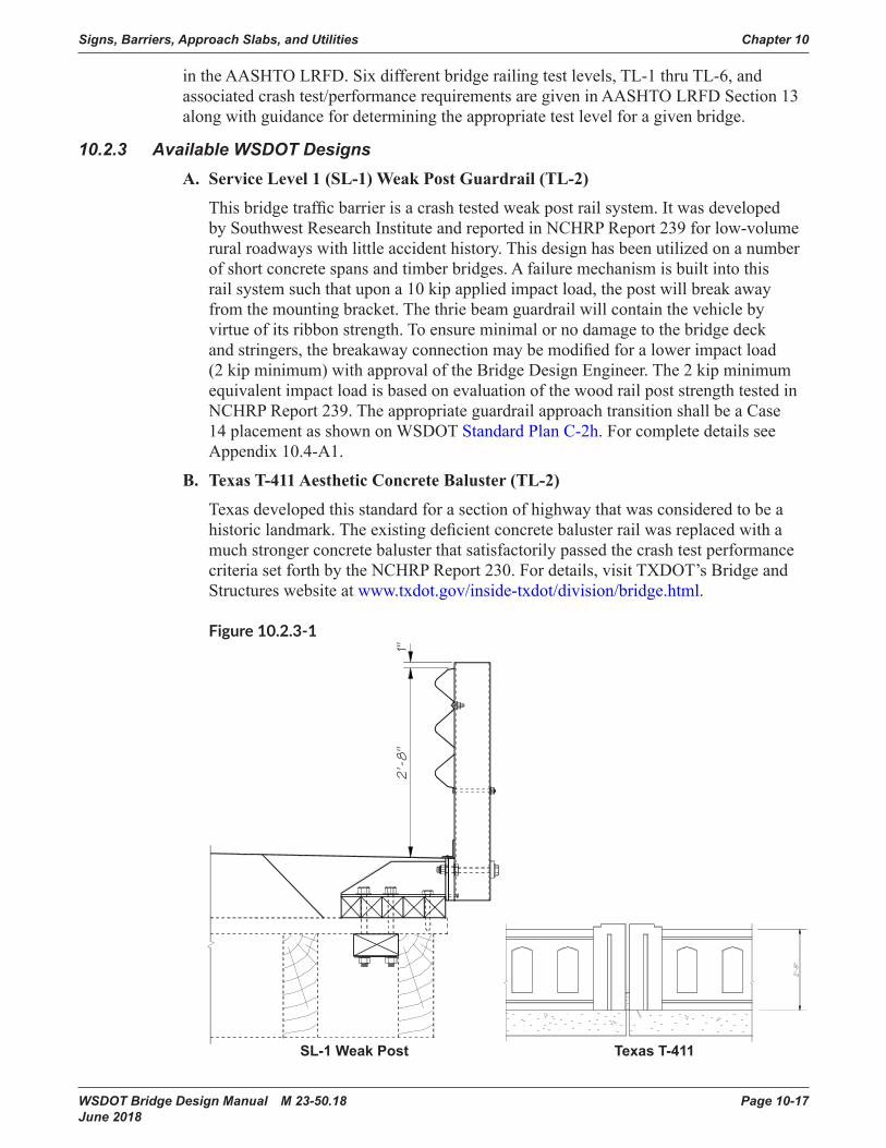
Thisbridgetrafficbarrierisacrashtestedweakpostrailsystem.ItwasdevelopedbySouthwestResearchInstituteandreportedinNCHRPReport239forlow-volumerural roadways with little accident history. This design has been utilized on a number of short concrete spans and timber bridges. A failure mechanism is built into this rail system such that upon a 10 kip applied impact load, the post will break away from the mounting bracket. The thrie beam guardrail will contain the vehicle by virtue of its ribbon strength. To ensure minimal or no damage to the bridge deck andstringers,thebreakawayconnectionmaybemodifiedforalowerimpactload(2 kip minimum) with approval of the Bridge Design Engineer. The 2 kip minimum equivalent impact load is based on evaluation of the wood rail post strength tested in NCHRPReport239.TheappropriateguardrailapproachtransitionshallbeaCase14 placement as shown on WSDOT Standard Plan C-2h. For complete details see Appendix 10.4-A1.
B. Texas T-411 Aesthetic Concrete Baluster (TL-2)
Texas developed this standard for a section of highway that was considered to be a historiclandmark.Theexistingdeficientconcretebalusterrailwasreplacedwithamuch stronger concrete baluster that satisfactorily passed the crash test performance criteriasetforthbytheNCHRPReport230.Fordetails,visitTXDOT’sBridgeandStructures website at www.txdot.gov/inside-txdot/division/bridge.html.
Figure 10.2.3-1
SL-1WeakPost TexasT-411

Chapter 10 Signs, Barriers, Approach Slabs, and Utilities
Page 10-18 WSDOT Bridge Design Manual M 23-50.18 June 2018
C. Traffic Barrier – 32″ F-Shape (TL-4)
Thisconfigurationwascrashtestedinthelate1960s,alongwiththeNewJerseyShape,underNCHRP230andagainatthistestlevelunderNCHRP350.Thesteepervertical shape tested better than the New Jersey face and had less of an inclination to roll vehicles over upon impact. For future deck overlays, an encroachment of 2.0 in.,leavinga1.0in.liphasbeensatisfactorilytestedforsafetyshapes,seeAASHTOArticle C13.7.3.2. This barrier height will require the use of a Bridge Railing Type Pedestrian railing to meet fall protection requirements. For complete details see Bridge Standard Drawings 10.2-A1 and 10.2-A2.
D. Traffic Barrier – 34″ Single Slope (TL-4)
ThisconcretetrafficbarriersystemwasdesignedbythestateofCaliforniainthe1990s to speed up construction by using the “slip forming” method of construction. ItwastestedunderNCHRP350.WSDOThasincreasedtheheightfrom32″to34″tomatchtheapproachtrafficbarrierheightandtoallowtheplacementofoneHMAoverlay.Duetoinherentproblemswiththe“slipforming”methodoftrafficbarrierconstructionWSDOThasincreasedtheconcretecoveronthetrafficsidefrom1½″to2½″.This barrier height will require the use of a Bridge Railing Type Pedestrian railing to meet fall protection requirements. For complete details, see Bridge Standard Drawing 10.2-A3.
Figure 10.2.3-2
32″F-Shape 34″SingleSlope

Signs, Barriers, Approach Slabs, and Utilities Chapter 10
WSDOT Bridge Design Manual M 23-50.18 Page 10-19 June 2018
E. Pedestrian Barrier (TL-4)
This crash tested rail system offers a simple to build concrete alternative to the New JerseyandF-Shapeconfigurations.ThissystemwascrashtestedunderbothNCHRP230and350.Sincethetrafficfacegeometryisbetterforpedestriansandbicyclists,WSDOT uses this system primarily in conjunction with a sidewalk. This barrier height will require the use of a Bridge Railing Type Pedestrian railing to meet fall protection requirements. For complete details, see Bridge Standard Drawing 10.2-A4.
F. Oregon 3-Tube Curb Mounted Traffic Barrier (TL-4)
Thisisanothercrashtestedtrafficbarrierthatoffersalightweight,see-throughoption.ThissystemwascrashtestedunderbothNCHRP230and350.Arigidthriebeam guardrail transition is required at the bridge ends. For details, see the Oregon Bridge and Structure website at www.oregon.gov/ODOT/HWY/ENGSERVICES/Pages/bridge_drawings.aspx.
Figure 10.2.3-3
32″Vertical Oregon 3-Tube
G. Traffic Barrier – 42″ F-Shape (TL-4 and TL-5)
Thisbarrierisverysimilartothe32″F-shapeconcretebarrierinthattheslopeofthefront surface is the same except for height. For complete details, see Bridge Standard Drawing 10.2-A5.

Chapter 10 Signs, Barriers, Approach Slabs, and Utilities
Page 10-20 WSDOT Bridge Design Manual M 23-50.18 June 2018
H. Traffic Barrier – 42″ Single Slope (TL-4 and TL-5)
ThisoptionoffersasimpletobuildalternativetotheShapeFconfiguration.Forcomplete details see Bridge Standard Drawing 10.2-A6.
Figure 10.2.3-4
42″F-Shape 42″SingleSlope
10.2.4 Design CriteriaA. Design Values
AASHTOLRFDAppendixA13shallbeusedtodesignbridgetrafficbarriersandtheir supporting elements (i.e. the deck).
ConcretetrafficbarriersshallbedesignedusingyieldlineanalysisasdescribedinAASHTOLRFDA13.3.1.TheimpactloadsontrafficbarriersshallbeappliedattheheightspecifiedforintendedTestLevelsinaccordancetotheAASHTOLRFDTableA13.2-1 “Design Forces for Traffic Railing”. WSDOT Standard F Shape, Single Slope, and Pedestrian barriers meet these requirements.
DeckoverhangssupportingtrafficbarriersshallbedesignedinaccordancewithAASHTOLRFDA13.4.ForconcretetrafficbarriersinDesignCase1,AASHTOrequires MS,thedeckoverhangflexuralresistance,tobegreaterthanMc of theconcretetrafficbarrierbase.Thisrequirementisconsistentwithyieldlineanalysis(seeAASHTOLRFDCA13.3.1),butresultsinoverconservativedeckoverhang designs.

Signs, Barriers, Approach Slabs, and Utilities Chapter 10
WSDOT Bridge Design Manual M 23-50.18 Page 10-21 June 2018
In order to prevent this unnecessary overdesign of the deck overhang, the nominal trafficbarrierresistancetotransverseloadRW(AASHTOLRFDA13.3.1)transferredfromthetrafficbarriertodeckoverhangshallnotexceed120percentofthedesignforce Ft(AASHTOLFRDTableA13.2-1)requiredforatrafficbarrier.ThedeckoverhangshallbedesignedinaccordancewiththerequirementsofAASHTOLRFDA13.4.2toprovideaflexuralresistanceMs, acting coincident with the tensile force T. At the inside face of the barrier Ms may be taken as:
for an interior barrier segment–Ms = Rw · H
LC + 2 · H
and for an end barrier segment–Ms = Rw · H LC + H
However,Ms need not be taken greater than Mc at the base. T shall be taken as:
for an interior barrier segment–T = Rw
LC + 2 · H
and for an end barrier segment–T = Rw
LC + H The end segment requirement may be waived if continuity between adjacent barriers
is provided.
WhenanHMAoverlayisrequiredforinitialconstruction,increasetheweightforShapeFtrafficbarrier.SeeSection 10.2.4.C for details.
B. Geometry
Thetrafficfacegeometryispartofthecrashtestandshallnotbemodified.ContacttheWSDOTBridgeandStructureOfficeBridgeRailSpecialistforfurtherguidance.
Thickeningofthetrafficbarrierispermissibleforarchitecturalreasons.Concreteclear cover must meet minimum concrete cover requirements but can be increased to accommodate rustication grooves or patterns.
C. Standard Detail Sheet Modifications
Whendesigninganddetailingabridgetrafficbarrieronasuperelevatedbridgedeckthe following guidelines shall be used:• Forbridgedeckswithasuperelevationof8percentorless,thetrafficbarriers
(and the median barrier, if any) shall be oriented perpendicular to the bridge deck.• Forbridgedeckswithasuperelevationofmorethan8percent,thetrafficbarrier
on the low side of the bridge (and median barrier, if any) shall be oriented perpendicular to an 8 percent superelevated bridge deck. For this situation, the trafficbarrieronthehighsideofthebridgeshallbeorientedperpendiculartothebridge deck.
Thestandarddetailsheetsaregenericandmayneedtobemodifiedforeachproject.Thepermissiblemodificationsare:• Removaloftheelectricalconduit,junctionbox,anddeflectionfittingdetails.• Removal of design notes.• Ifthetrafficbarrierdoesnotcontinueontoawall,removeW1andW2rebar
references.• Removal of the non-applicable guardrail end connection details and verbiage.

Chapter 10 Signs, Barriers, Approach Slabs, and Utilities
Page 10-22 WSDOT Bridge Design Manual M 23-50.18 June 2018
• Ifguardrailisattachedtothetrafficbarrier,useeitherthethriebeamendsection“DesignF”detailorthew-beamendsection“DesignF”detail.Ifthetrafficbarrier continues off the bridge, approach slab, or wall, remove the following:
• Guardrail details from all sheets.• Conduitendflaredetail.• ModifiedendsectiondetailandR1AorR2Arebardetailsfromallsheets.• End section bevel.• Increasethe3″toedimensionoftheShapeFtrafficbarriersupto6″toaccommodateHMAoverlays.

Signs, Barriers, Approach Slabs, and Utilities Chapter 10
WSDOT Bridge Design Manual M 23-50.18 Page 10-23 June 2018
Tabl
e 10
.2.4
-1
Inte
rior
End
*In
terio
rE
nd*
Inte
rior
End
*In
terio
rE
nd*
Inte
rior
End
*In
terio
rE
nd*
Ave
rage
Mc (
ft-ki
ps/ft
)20
.55
20 .5
519
.33
19 .3
325
.93
25 .9
322
.42
22 .4
225
.93
25 .9
322
.42
36 .0
4M
c at B
ase
(ft-k
ips/
ft)27
.15
27 .1
526
.03
26 .0
332
.87
32 .8
730
.66
30 .6
632
.87
32 .8
730
.66
49 .5
2M
w (f
t-kip
s)42
.47
46 .0
446
.01
43 .1
672
.54
71 .7
260
.66
57 .2
698
.23
96 .9
383
.85
79 .1
2L c
(ft)
8 .62
4 .76
9 .30
4 .81
10 .7
75 .
3210
.63
5 .21
15 .0
59 .
3914
.99
8 .87
Rw (k
ips)
132 .
8273
.31
126 .
9265
.69
159 .
6278
.83
136 .
1766
.81
223 .
0013
9 .20
192 .
0218
2 .61
F t (k
ips)
54 .0
054
.00
54 .0
054
.00
54 .0
054
.00
54 .0
054
.00
124 .
0012
4 .00
124 .
0012
4 .00
1 .2*
F t (k
ips)
64 .8
064
.80
64 .8
064
.80
64 .8
064
.80
64 .8
064
.80
148 .
8014
8 .80
148 .
8014
8 .80
Des
ign
Rw (k
ips)
64 .8
064
.80
64 .8
064
.80
64 .8
064
.80
64 .8
064
.80
148 .
8013
9 .20
148 .
8014
8 .80
Rw*H
/(Lc+
aH) (
ft-ki
ps/ft
)**
12 .3
923
.28
12 .2
724
.01
9 .72
19 .5
99 .
8019
.83
23 .6
237
.79
23 .6
942
.11
Des
ign
Ms (
ft-ki
ps/ft
)12
.39
23 .2
812
.27
24 .0
19 .
7219
.59
9 .80
19 .8
323
.62
32 .8
723
.69
42 .1
1D
esig
n T
(kip
s/ft)
4 .65
8 .73
4 .33
8 .47
3 .65
7 .35
3 .68
7 .44
6 .75
10 .8
06 .
7712
.03
As r
equi
red
(in2 /ft
)0 .
290 .
570 .
290 .
590 .
170 .
350 .
200 .
410 .
430 .
600 .
490 .
91A
s pro
vide
d (in
2 /ft)
0 .41
0 .62
0 .41
0 .62
0 .41
0 .62
0 .41
0 .62
0 .59
0 .89
0 .59
0 .97
S1 B
ars
#5 @
9 in
#5 @
6 in
#5 @
9 in
#5 @
6 in
#5 @
9 in
#5 @
6 in
#5 @
9 in
#5 @
6 in
#6 @
9 in
#6 @
6 in
#6 @
8 in
#6 @
5 .5
in
*Tra
ffic
barr
ier c
ross
sec
tiona
l dim
ensi
ons
and
rein
forc
emen
t use
d fo
r cal
cula
tion
of e
nd s
egm
ent p
aram
eter
s ar
e th
e sa
me
as in
terio
r seg
men
ts (e
xcep
t TL-
5 S
ingl
e S
lope
42
in . b
arrie
rw
here
end
sec
tion
rein
forc
emen
t diff
ers
from
inte
rior s
egm
ents
) . P
aram
eter
s fo
r mod
ified
end
seg
men
ts s
hall
be c
alcu
late
d pe
r AA
SH
TO-L
RFD
arti
cle
A13
.3, A
13 .4
, and
the
WS
DO
T B
DM
.**
a =
1 fo
r an
end
segm
ent a
nd 2
for a
n in
terio
r seg
men
tLo
ads
are
base
d on
veh
icle
impa
ct o
nly .
For
dec
k ov
erha
ng d
esig
n, th
e de
sign
er m
ust a
lso
chec
k ot
her l
imit
stat
es p
er L
RFD
A13
.4 .1
.f v
= 60
ksi
f' c=
4 ks
i
Barrie
rImpactDesignFo
rcesonTrafficBarrie
r&DeckOverhang
(TL-
5)(T
L-5)
Traf
fic B
arrie
r D
esig
n
Dec
k O
verh
ang
Des
ign
Type
F 4
2 in
.S
ingl
e S
lope
42
in .
Dec
k to
B
arrie
r R
einf
orce
men
tPar
amet
ers
Type
F 3
2 in
.S
ingl
e S
lope
34
in .
Sin
gle
Slo
pe 4
2 in
.(T
L-4)
(TL-
4)(T
L-4)
Type
F 4
2 in
.(T
L-4)

Chapter 10 Signs, Barriers, Approach Slabs, and Utilities
Page 10-24 WSDOT Bridge Design Manual M 23-50.18 June 2018
D. Miscellaneous Design Information• Showthebackofpavementseatinthe“Plan–TrafficBarrier”detail.• Atroadwayexpansionjoints,showtrafficbarrierjointsnormaltocenterline
except as shown on sheets Appendix 9.1-A1-1 and 9.1-A2-1.• Whenanoverlayisrequired,the2′-8″minimumdimensionshowninthe“TypicalSection–TrafficBarrier”shallbereferencedtothetopoftheoverlay.
• When bridge lighting is part of the contract, include the lighting bracket anchorage detail sheet.
• Approximatequantitiesforthetrafficbarriersheetsare:
BarrierType ConcreteWeight(lb/ft) SteelWeight(lb/ft)32″ F-shape (3″ toe) 460 18 .632″ F-shape (6″ toe) 510 19 .1
34″ Single Slope 490 16 .142″ F-shape (3″ toe) 710 25 .842″ F-shape (6″ toe) 765 28 .4
42″ Single Slope 670 22 .932″ Pedestrian 640* 14 .7
Using concrete class 4000 with a unit weight of 155 lb/ft3
*with 6″ sidewalk, will vary with sidewalk thickness
• Steel Reinforcement Bars: S1 & S2 or S3 & S4 and W1 & W2 bars (if used) shall be included in the Bar List.
S1, S3, and W1 bars shall be epoxy coated.

Signs, Barriers, Approach Slabs, and Utilities Chapter 10
WSDOT Bridge Design Manual M 23-50.18 Page 10-25 June 2018
10.3 AtGradeConcreteBarriers10.3.1 Differential Grade Concrete Barriers
Thetopofthedifferentialgradeconcretebarriershallhaveaminimumwidthof6″.Ifaluminaire or sign is to be mounted on top of the differential grade concrete barrier, then thewidthshallbeincreasedtoaccommodatethemountingplateand6″ofcleardistanceoneachsideoftheluminaireorsignpole.ThetransitionflarerateshallfollowtheDesign Manual M 22-01.
A. Differential Grade Concrete Barriers
Concrete barriers at grade are sometimes required in median areas with different roadway elevations on each side. The standard Single Slope barrier can be used for agradedifferenceupto10″fora2′-10″safetyshapeandupto6″fora3′-6″safetyshape. See Standard Plans C-70.10 and C-80.10 for details.
Ifthedifferenceingradeelevationsis4′-0″orless,thentheconcretebarriershallbedesignedasarigidsysteminaccordancewithAASHTOLRFDwiththefollowing requirements:
1. AllapplicableloadsshallbeappliedinaccordancetoAASHTOLRFDSection3.The structural capacity of the differential grade concrete barrier and supporting elements shall be designed for the required Test Level (TL) vehicle impact design forcesinaccordancewithAASHTOLRFDSections5and13.Anysectionalongthe differential grade barrier and supporting elements shall not fail in shear, bending, or torsion when the barrier is subjected to the TL impact forces.
2. For soil loads without vehicle impact loads, the concrete barrier shall be designed as a retaining wall (barrier weight resists overturning and sliding). Passive soil resistance may be considered with concurrence by the geotechnical engineer.
3. Vehicle impact loads shall be applied on the side of the concrete barrier retaining soilifthereistrafficonbothsides.ThevehicleimpactloadsshallbeappliedattheheightspecifiedforintendedTestLevelsinaccordancetotheAASHTOLRFDSection 13, Table A13.2-1 “Design Forces for Traffic Railing (32-inch for TL-4, and 42-inch for TL-5)”.
4. Forsoilloadswithvehicleimpactloads,theAASHTOLRFDExtremeEventloading for vehicular collision shall also be analyzed. Equivalent Static Load (ESL)perNCHRPReport663maybeappliedasthetransversevehicleimpactload for evaluating sliding, bearing, and overturning only. For TL-4 barrier systems, the ESL shall be 10 kips and for TL-5, the ESL shall be 23 kips. The point of rotation for overturning shall be taken at the toe of barrier. Sliding resistance factor shall be 0.8 and overturning resistance factor shall be 0.5 (supersedesAASHTO10.5.5.3.3).
5. The effective length of the concrete barrier required for stability shall be no more than 10 times the overall height, but not to exceed the length between barrier expansion joints (or one precast section). The barrier shall act as a rigid body behavior and shall be continuous throughout this length of barrier. Any coupling between adjacent barrier sections or friction that may exist between free edges of barrier and the surrounding soil shall be neglected.

Chapter 10 Signs, Barriers, Approach Slabs, and Utilities
Page 10-26 WSDOT Bridge Design Manual M 23-50.18 June 2018
6. A special impact analysis shall be performed at the barrier ends if the barrier terminates without being connected to a rigid object or dowelled to another barrier.Differentialbarrierdeflectionfrombarrierimpactmaycauseavehicleto“snag”ontheundeflectedbarrier.Thebarrierdepthmayneedtobeincreasedattheendtopreventthisdeflection.
7. Thedifferentialgradetrafficbarriershallhavedummyjointsat8to12footcenters based on project requirements.
8. Full depth expansion joints with shear dowels at the top will be required at intervalsbasedonanalysisbutnottoexceeda120′-0″maximumspacing.
9. Barrierbottomshallbeembeddedaminimum6″belowroadway.Roadwaysubgrade and ballast shall be extended below whole width of differential grade barrier.
Mediantrafficbarrierswithagradedifferencegreaterthan4′-0″shallbedesignedasstandardplanretainingwallswithatrafficbarrieratthetopandabarriershapeatthecut face.
10.3.2 TrafficBarrierMomentSlabA. General
TheguidelinesprovidedhereinarebasedonNCHRPReport663withtheexceptionthat a resistance factor of 0.5 shall be used to determine rotational resistance. This guidelineisapplicableforTL-4andTL-5barriersystemsasdefinedinSection13ofAASHTOLRFD Bridge Design Specifications.
Figure 10.3.2-1 Global Stability of Barrier–Moment Slab System
Ls = 23 K Static Equivalent for TL5 Barriers
ha = Moment Arm Top of Barrier to Point of Rotations
Ls = 10 K Static Equivalent for TL3 and TL4 Barriers
La
Varies with Wall Type
Compacted Backfill
Roadway Base Course
Pavement Overburden
P
A = Point of Rotation
C.G.
W
Lw
B. Guidelines for Moment Slab Design
1. Structural Capacity
The structural capacity of the barrier and concrete moment slab shall be designed using impulse loads at appropriate Test Level (TL-4 and TL-5) applied to the topofthebarrierinaccordancewithSections5and13ofAASHTOLRFD.Anysection along the moment slab shall not fail in shear, bending, or torsion when the barrier is subjected to the design impact loads. The torsion capacity of the momentslabmustbeequaltoorgreaterthanthetrafficbarriermomentgeneratedbythespecifiedTLstaticequivalentofthevehicleimpulseload.

Signs, Barriers, Approach Slabs, and Utilities Chapter 10
WSDOT Bridge Design Manual M 23-50.18 Page 10-27 June 2018
The moment slab shall be designed as a deck supporting barrier in accordance to AASHTOLRFDA13.4.2asmodifiedbyBDMSection10.2.4.A.Themomentslab reinforcement shall be designed to resist combined forces from the moment MS (kip-ft/ft) and the tensile force T (kip/ft). MS and T are determined from the lesser of the ultimate transverse resistance of barrier RW (kip) and 120 percent of transverse vehicle impact force FT (kip). MS is not to be exceeded by the ultimate strength of barrier at its base MC (kip-ft/ft).
2. Global Stability
Bearing stress, sliding, and overturning stability of the moment slab shall be based onanEquivalentStaticLoad(ESL)appliedattheheightspecifiedforintendedTestLevelsinaccordancetotheAASHTOLRFDSection13,TableA13.2-1“Design Forces for Traffic Railing”. For TL-4 barrier systems, the ESL shall be 10 kips. For TL-5 barrier systems, the ESL shall be 23 kips.
The Equivalent Static Load (ESL) is assumed to distribute over the length of continuous moment slab through rigid body behavior. Barrier shall also be continuous or have shear connections between barrier sections if precast throughout this length of moment slab. Any coupling between adjacent moment slabs or friction that may exist between free edges of the moment slab and the surrounding soil should be neglected.
3. Minimum and Maximum Dimensions
Theminimumheightofthetrafficbarrierportionofthemomentslabshallbe42inchesabovethefinishedroadwaysurface.
Moment slabs shall have a minimum width of 4.0 feet measured from the point of rotation to the heel of the slab and a minimum average depth of 0.83 feet. Moment slabs meeting these minimum requirements are assumed to provide rigid body behavior up to a length of 60 feet limited to the length between moment slab joints.
Rigid body behavior may be increased from 60 feet to a maximum of 120 feet if the torsional rigidity constant of the moment slab is proportionately increased and the reinforcing steel is designed to resist combined shear, moment, and torsion from TL static equivalent of the vehicle impulse loads.
Forexample:RigidBodyLength=(J’/J60)x(60ft.)<120feet
The torsional rigidity constant for moment slabs shall be based on a solid rectangle using the following formula:
Where:
2a = total width of moment slab 2b = average depth of moment slab
For example: Minimum Moment Slab Width = 48 inches: a = 24 inches Minimum Moment Slab Average Depth = 10 inches: b = 5 inches J = J60 = 13,900 in4

Chapter 10 Signs, Barriers, Approach Slabs, and Utilities
Page 10-28 WSDOT Bridge Design Manual M 23-50.18 June 2018
4. Sliding of the Barrier
The factored static resistance to sliding (φP) of the barrier-moment slab system along its base shall satisfy the following condition:
φP≥γLs (1)Where: Ls = Equivalent Static Load (10 kips for TL-3 or TL-4, 23 kips for TL-5) φ =resistancefactor(0.8)SupersedesAASHTO10.5.5.3.3—OtherExtremeLimit
States γ =loadfactor(1.0)forTL-3andTL-4[crashtestedextremeevent]
loadfactor(1.2)forTL-5[untestedextremeevent] P = static resistance (kips)
P shall be calculated as:P = W tan φr
(2)
Where: W = weight of the monolithic section of barrier and moment slab between joints or
assumed length of rigid body behavior whichever is less, plus any material laying on top of the moment slab
φr = friction angle of the soil on the moment slab interface (°)
If the soil-moment slab interface is rough (e.g., cast in place), φr is equal to the friction angle of the soil φs. If the soil-moment slab interface is smooth (e.g., precast), tan φr shall be reduced accordingly (0.8 tan φs).
5. Overturning of the Barrier
The factored static moment resistance (φM) of the barrier-moment slab system to over-turning shall satisfy the following condition:
φM≥γLs ha (3)Where: A = point of rotation, where the toe of the moment slab makes contact with compacted
backfill adjacent to the fascia wall Lw = width of moment slab Ls = Equivalent Static Load (10 kips for TL-3 and TL-4) (23 kips for TL-5) φ =resistancefactor(0.5)SupersedesAASHTO10.5.5.3.3—OtherExtremeLimit
StatesandNCHRPReport663 γ =loadfactor(1.0)forTL-3andTL-4[crashtestedextremeevent]
loadfactor(1.2)forTL-5[untestedextremeevent] ha = moment arm taken as the vertical distance from the point of impact due to the
dynamic force (top of the barrier) to the point of rotation A M = static moment resistance (kips-ft)
M shall be calculated as: M = W (La) (4)
W = weight of the monolithic section of barrier and moment slab between joints or assumed length of rigid body behavior whichever is less, plus any material laying on top of the moment slab
La = horizontal distance from the center of gravity of the weight W to point of rotation A

Signs, Barriers, Approach Slabs, and Utilities Chapter 10
WSDOT Bridge Design Manual M 23-50.18 Page 10-29 June 2018
The moment contribution due to any coupling between adjacent moment slabs, shear strength of the overburden soil, or friction which may exist between the backside of the moment slab and the surrounding soil shall be neglected.
C. Guidelines for the Soil Reinforcement
Design of the soil reinforcement shall be in accordance with the Geotechnical Design Manual Chapter 15.
D. Design of the Wall Panel
The wall panels shall be designed to resist the dynamic pressure distributions as definedintheGeotechnical Design Manual Chapter 15.
Thewallpanelshallhavesufficientstructuralcapacitytoresistthemaximumdesignrupture load for the wall reinforcement designed in accordance with the Geotechnical Design Manual Chapter 15.
The static load is not included because it is not located at the panel connection.
10.3.3 Precast Concrete BarrierA. Concrete Barrier Type 2
“Concrete Barrier Type 2” (see Standard Plan C-8) may be used on bridges formedianapplicationsorfortemporarytrafficcontrolbasedonthefollowing guidelines:
1. For temporary applications, no anchorage is required if there is 2 feet or greater slidedistancebetweenthebackofthetrafficbarrierandanobjectand3feetorgreater to the edge of the bridge deck or a severe drop off (see Design Manual M 22-01).
2. For permanent applications in the median, no anchorage will be required if there isa3footorgreaterslidedistancebetweenthetrafficbarrierandthetrafficlane.
3. Fortemporaryapplications,thetrafficbarriershallnotbeplacedcloserthan9 inches to the edge of a bridge deck or substantial drop-off and shall be anchored (see Standard Plans K-80.35 and K-80.37).
4. Thetrafficbarriershallnotbeusedtoretainsoilthatisslopedorgreaterthanthebarrierheightorsoilthatsupportsatrafficsurcharge.
B. Concrete Barrier Type 4 and Alternative Temporary Concrete Barrier
“Concrete Barrier Type 4 (see the Standard Plan C-8a),isnotafreestandingtrafficbarrier. This barrier shall be placed against a rigid vertical surface that is at least as tallasthetrafficbarrier.Inaddition,AlternativeTemporaryConcreteBarrierType4–Narrow Base (Standard Plan K-80.30) shall be anchored to the bridge deck as shown in Standard Plan K-80.37. The “Concrete Barrier Type 4 and Alternative Temporary Concrete Barrier” are not designed for soil retention.

Chapter 10 Signs, Barriers, Approach Slabs, and Utilities
Page 10-30 WSDOT Bridge Design Manual M 23-50.18 June 2018
10.4 BridgeTrafficBarrierRehabilitation10.4.1 Policy
Thebridgetrafficbarrierretrofitpolicyis:“tosystematicallyimproveorreplaceexistingdeficientrailswithinthelimitsofroadwayresurfacingprojects.”Thisisaccomplishedby:• Utilizing an approved crash tested rail system that is appropriate for the site or• DesigningatrafficbarriersystemtothestrengthrequirementssetforthbySection2ofAASHTOStandard Specifications for Highway Bridges, 17th edition.
10.4.2 GuidelinesA strength and geometric review is required for all bridge rail rehabilitation projects. If the strength of the existing bridge rail is unable to resist a 10 kip barrier impact design loadorhasnotbeencrashtested,thenmodificationsorreplacementwillberequiredtoimproveitsredirectionalcharacteristicsandstrength.Bridgesthathavedeficientbridgetrafficbarriersweredesignedtooldercodes.
TheAASHTOLFDloadof10kipsshallbeusedintheretrofitofexistingbridgetrafficbarrier systems constructed prior to the year 2000.
TheuseoftheAASHTOLRFDcriteriatodesignbridgetrafficbarrierrehabswillresultinabridgedeckthathasinsufficientreinforcementtoresistmomentfromatrafficbarrierimpactloadandwillincreasetheretrofitcostduetoexpensivedeckmodifications.
If the design of the bridge rehabilitation includes other bridge components that will be designedusingAASHTOLRFDthenthefollowingminimumequivalentExtremeEvent(CT)trafficbarrierloadingcanbeused:
Flexure = (1.3)*(1.67)*(10 kip) / (0.9) = 24.10 kip Shear = (1.3)*(1.67)*(10 kip) / (0.85) = 25.54 kip
10.4.3 Design CriteriaStandard thrie beam guardrail post spacing is 6′-3″exceptfortheSL-1WeakPost,whichis at 8′-4″.Postspacingcanbeincreasedupto10′-0″ifthethriebeamguardrailisnested(doubled up).
Gaps in the guardrail are not allowed because they produce snagging hazards. The exceptions to this are:• Movable bridges at the expansion joints of the movable sections.• Attrafficgatesanddropdownnetbarriers.• At stairways.
Design F guardrail end sections will be used at the approach and trailing end of these gaps.
ForBridgeTrafficBarrierRehabilitationthefollowinginformationwillbeneededfromtheRegionDesignoffice:• Bridge Site Data Rehabilitation Sheet – DOT Form 235-002A.• Photos, preferably digital JPEG format.• Layout with existing dimensions.

Signs, Barriers, Approach Slabs, and Utilities Chapter 10
WSDOT Bridge Design Manual M 23-50.18 Page 10-31 June 2018
• StandardPlanthriebeamguardrailtransitions(selectedbyRegionDesignoffice)tobeusedateachcornerofthebridge(contactbridgesandstructuresofficeforthriebeam height).
• Location of any existing utilities.• Measurements of existing ACP to top of curb at the four corners, midpoints andthelocationsofminimumandmaximumdifference(fivelocationseachsideas a minimum).
• Diagram of the location of Type 3 anchors, if present, including a plan view with vertical and horizontal dimensions of the location of the Type 3 anchor connection relative to the intersecting point of the back of pavement seat with the curb line.
• The proposed overlay type, quantities of removal and placement.• Fortimberbridges,thefieldmeasurementofthedistancefromtheedgeofbridgedecktothefirstandsecondstringerisrequiredformountingplatedesign.
PlacementoftheretrofitsystemwillbedeterminedfromtheDesign Manual M 22-01. Exceptions to this are bridges with sidewalk strength problems, pedestrian access issues, or vehicle snagging problems.
10.4.4 WSDOT Bridge Inventory of Bridge RailsTheWSDOTBridgePreservationOfficemaintainsaninventoryofallbridgesinthestateon the State of Washington Inventory of Bridges.Concretebalustersaredeficientforcurrentlateralloadcapacityrequirements.Theyhaveapproximately 3 kips of capacity whereas 10 kips is required.The combination high-base concrete parapet and metal rail may or may not be considered adequate depending upon the rail type. The metal rail Type R, S, and SB attached to the top of the high-base parapet are considered capable of resisting the required 5 kips of lateral load. Types 3, 1B, and 3A are considered inadequate. See the Design Manual M 22-01 for replacement criteria.
10.4.5 AvailableRetrofitDesignsA. Washington Thrie Beam Retrofit of Concrete Balusters This system consists of thrie beam guardrail stiffening of existing concrete baluster
rails with timber blockouts. The Southwest Research Institute conducted full-scale crashtestsofthisretrofitin1987.ResultsofthetestsweresatisfactoryandcompliedwithcriteriaforaTestLevel2(TL-2)categoryintheGuideSpecifications.Forcomplete details see Bridge Standard Drawing 10.4-A1-1.
B. Delaware Thrie Beam Guardrail This crash tested rail system can be utilized at the top of a raised concrete sidewalk to
separatepedestriantrafficfromthevehiculartrafficorcanbemounteddirectlytothetopoftheconcretedeck.ForcompletedetailsseeThrieBeamRetrofitConcreteCurbin Appendix 10.4-A1-3.
C. Concrete Parapet Retrofit This is similar to the Delaware system. For complete details see Appendix 10.4-A1-2.

Chapter 10 Signs, Barriers, Approach Slabs, and Utilities
Page 10-32 WSDOT Bridge Design Manual M 23-50.18 June 2018
D. SL-1 Weak Post This design has been utilized on some short concrete spans and timber bridges.
A failure mechanism is built into this rail system so that upon impact with a 10 kip load the post will break away from the mounting bracket. The thrie beam guardrail will contain the vehicle by virtue of its ribbon strength. To ensure minimal damage tothebridgedeckandstringers,thebreakawayconnectionmaybemodifiedforalower impact load (2 kip minimum) with approval of the Bridge Design Engineer. For complete details, see Bridge Standard Drawing 10.4-A1-4.
10.4.6 AvailableReplacementDesignsA. Traffic Barrier – Shape F Retrofit ThisisWSDOT’spreferredreplacementofdeficienttrafficbarriersandparapetson
high volume highways with a large truck percentage. All interstate highway bridges shall use this type of barrier unless special conditions apply. For complete details see Bridge Standard Drawing 10.4-A2.
Signs, Barriers, Approach Slabs, and Utilities Chapter 10
WSDOT Bridge Design Manual M 23-50.18 Page 10-33 June 2018
10.5 BridgeRailing10.5.1 Design
WSDOT pedestrian and bicycle/pedestrian railings are designed in accordance with Chapter13inAASHTOLRFD.AASHTOLRFDcallsforaminimumof42″forbicyclerailingswhereasWSDOTrequiresaminimumheightof54″onstructures.Therailingsin Section 10.5.2 are not designed for vehicular impact loads assuming location is lowspeed,locationisoutsideofDesignClearZoneasdefinedintheDesign Manual Chapter 1600, or location has minimal safety consequence from collapse of railing. Railings for other locations shall be designed for vehicular impact loads in accordance with Chapter 13and/or15intheAASHTOLRFD. Emergency and maintenance access shall be considered.
Pedestrian and bicycle railings shall be designed using a Live Load factor of 1.75.
Fall Protection railing shall meet the requirements of WAC 296-155-24609 and WAC 296-155-24615(2).
BalusterspacingshallbeinaccordancewithAASHTOLRFDChapter13.8.Theusea more restrictive baluster spacing, such as IBC 1013.4, may be acceptable on a case-by-case basis. Request to use a more restrictive baluster spacing shall come from the WSDOT Project Engineer and shall be approved by the Bridge Design Engineer.
10.5.2 Railing TypesA. Bridge Railing Type Pedestrian
Thispedestrianrailingisdesignedtositontopofthe32″and34″trafficbarriersand to meet pedestrian and fall protectionheightrequirementsof42″.Forcompletedetails see Bridge Standard Drawing 10.5-A1.
B. Bridge Railing Type BP and S-BP – 22 Inch
TheserailingsaredesignedtomeetWSDOT’sminimumbicycleheightrequirementsof54″,andsitontopofthe32″and34″trafficbarriers.
Therearetwoversions—theBPandS-BP.TheBPisthestandardrailingandismadeout of aluminum. The S-BP is the steel version designed for use in rural areas because of aluminum theft. For complete details see Bridge Standard Drawing 10.5-A2 and 10.5-A3.
C. Bridge Railing Type BP and S-BP – 12 Inch
TheserailingsaredesignedtomeetWSDOT’sminimumbicycleheightrequirementsof54″,andsitontopofthe42″trafficbarriers.ForcompletedetailsseeBridgeStandard Drawing 10.5-A6 and 10.5-A7.
D. Pedestrian Railing
This railing is designed to sit on top of a six-inch curb on the exterior of a bridge sidewalk.Itmeetsthebicycleheightrequirementsof54″.ForcompletedetailsseeAppendix 10.5-A4.

Chapter 10 Signs, Barriers, Approach Slabs, and Utilities
Page 10-34 WSDOT Bridge Design Manual M 23-50.18 June 2018
E. Bridge Railing Type Snow Fence
This railing is designed to prevent large chunks of plowed snow from falling offthebridgeontotrafficbelow.ForcompletedetailsseeAppendix10.5-A5-2 and 10.5-A5-5.
F. Bridge Railing Type Chain Link Fence
This railing is designed to minimize the amount of objects falling off the bridge on totrafficbelow.The design loading shall include pedestrian loads and wind loads as specifiedinAASHTOLRFD.Thisdetailcanberaisedto10’–0”forapplicationsover railroad lines. For complete details see Appendix 10.5-A5-4.

Signs, Barriers, Approach Slabs, and Utilities Chapter 10
WSDOT Bridge Design Manual M 23-50.18 Page 10-35 June 2018
10.6 BridgeApproachSlabsBridge approaches typically experience two types of settlement, global and local. Global settlement is consolidation of the deeper natural foundation soils. Local settlement is mainlycompressionoffillmaterialsdirectlybeneaththeapproachpavementduetoconstruction. The combination of global and local settlements adjacent to the bridge end piers form the characteristic “bump” in the pavement at the bridge. The approach slabsignificantlyreduceslocalsettlementandwillprovideatransitiontothelongtermroadway differential settlements. Generally, abutments with a deep foundation will have greater differential roadway settlements than spread footing foundations.
When Are Bridge Approach Slabs Required – Bridge approach slabs are required for all new and widened bridges, except when concurrence is reached between the GeotechnicalBranch,theRegionDesignProjectEngineerOffice,andtheBridgeandStructuresOffice,thatapproachslabsarenotappropriateforaparticularsite.Inaccordance with Design Manual M 22-01, the State Geotechnical Engineer will include a recommendation in the geotechnical report for a bridge on whether or not bridge approach slabs should be used at the bridge site. Factors considered while evaluating the need for bridge approach slabs include the amount of expected settlement and the type of bridge structure.
Standard Plan A-40.50 – The Standard Plan A-40.50 is available for the Local Agencies (orothers)touseorreferenceinacontract.BridgeandStructuresOfficedesignswillprovide detailed information in a customized approach slab Plan View and show the approach slab length on the Bridge Layout Sheet.
Bridge Runoff – Bridge runoff at the abutments shall be carried off and collected at least 10 feet beyond the bridge approach slab. Drainage structures such as grate inlets and catch basins shall be located in accordance with Standard Plan B-95.40 and the recommendationsoftheHydraulicsBranch.
Approach Pay Item –All costs in connection with constructing bridge approach slabs are included in the unit contract price per square yard for “Bridge Approach Slab.” The pay item includes steel reinforcing bars, approach slab anchors, concrete, and compression seals.
10.6.1 NotestoRegionforPreliminaryPlanAll bridge preliminary plans shall show approach slabs at the ends of the bridges. In the NotestoRegioninthefirstsubmittalofthePreliminaryPlantotheRegion,thedesignershall ask the following questions:
1. Bridge approach slabs are shown for this bridge, and will be included in the Bridge PS&E. Do you concur?
2. The approach ends of the bridge approach slabs are shown normal to the survey line (a) with or (b) without steps (the designer shall propose one alternative). Do you concur?
3. Please indicate the pavement type for the approach roadway.
Depending on the type and number of other roadway features present at the bridge site (such as approach curbs and barriers, drainage structures, sidewalks, utilities and conduit pipes) or special construction requirements such as staged construction, other questions in the Notes to Region pertaining to the bridge approach slabs may be appropriate.

Chapter 10 Signs, Barriers, Approach Slabs, and Utilities
Page 10-36 WSDOT Bridge Design Manual M 23-50.18 June 2018
Special staging conditions exist when the abutment skew is greater than 30° and for wide roadway widths. This includes bridge widenings with (or without) existing bridge approach slabs. The preliminary plan should include details showing how these conditions are being addressed for the bridge approach slabs, and the designer shall include appropriate questions in the Notes to Region asking for concurrence with the proposed design.
10.6.2 Bridge Approach Slab Design CriteriaThe standard bridge approach slab design is based on the following criteria:
1. ThebridgeapproachslabisdesignedasaslabinaccordancewithAASHTOLRFD.(Strength Limit State, IM = 1.33, no skew).
2. The support at the roadway end is assumed to be a uniform soil reaction with abearinglengththatisapproximately⅓thelengthoftheapproachslab,or25′/3=8′.
3. The Effective Span Length (Seff), regardless of approach length, is assumed to be: 25′approach–8′=17′
4. Longitudinalreinforcingbarsdonotrequiremodificationforskewedapproachesupto30degreesorforslablengthsgreaterthan25′.
5. Theapproachslabisdesignedwitha2″concretecovertothebottomreinforcing.
10.6.3 Bridge Approach Slab DetailingThe bridge approach slab and length along center line of project shall be shown in the Plan View of the Bridge Layout sheet. The Bridge Plans will also include approach slab information as shown in Bridge Standard Drawings 10.6-A1-1, 10.6-A1-2, and 10.6-A1-3.TheApproachSlabPlansheetsshouldbemodifiedasappropriatetomatchthebridgesiteconditions.ApproachslabPlanViewsshallbecustomizedforthespecificproject and all irrelevant details shall be removed.
PlanViewdimensionsshalldefinetheplanareaoftheapproachslab.Theminimumdimensionfromthebridgeis25′.Ifthereareskewedends,thendimensionsshallbeprovided for each side of the slab, or a skew angle and one side, in addition to the width. For slabs on a curve, the length along the project line and the width shall be shown.
SimilartoBridgeTrafficBarrierdetailing,approachslabsteeldetailingshallshowsize, spacing, and edge clearance. The number and total spaces can be determined by thecontractor.Ifapplicable,thetrafficbarrierAS1andAS2alongwiththeextratoptransverse bar in the slab shall be shown in the Plan View. AS1 bars shall be epoxy coated. Also, remember that the spacing of the AS1 bars decreases near joints. When the skew is greater than 20 degrees, then AP8 bars shall be rotated at the acute corners of the bridge approach slab.
Bending diagrams shall be shown for all custom reinforcement. All Bridge Approach SlabsheetswillhavetheAP2andAP7bars.Ifthereisatrafficbarrier,thenAP8,AS1,and AS2 bars shall be shown.
Longitudinal contraction joints are required on bridge approach slabs wider than 40 ft. or where steps are used on skewed alignments. Joints shall be located at lane lines or median barrier and in accordance with Bridge Standard Drawing 10.6-A1-2. If joints are to be sawcut,cuttingshalloccurassoonaspossibleafterfinishingtheconcrete,butaftertheconcrete has set enough not to be torn or damaged by the blade. Additionally, cutting shall

Signs, Barriers, Approach Slabs, and Utilities Chapter 10
WSDOT Bridge Design Manual M 23-50.18 Page 10-37 June 2018
occur before shrinkage cracks start to appear, but no later than 48 hours after concrete placement.Early-entrysawingequipmentistypicallyusedwithin4hoursafterfinishingthe slab, and conventional sawing equipment is typically used between 4 and 12 hours, but may vary depending on the concrete mix design and environmental conditions.
Additional layout and details may be required to address special roadway features and construction requirements such as: roadway curbs and barriers, sidewalks, utilities and conduitsandstaging.Thismeans,ifsidewalksandinteriorbarriers(suchastraffic-pedestrian barriers) are present, special details will be required in the Bridge Plans to show how the sidewalks and interior barriers are connected to and constructed upon the bridge approach slab. If the bridge construction is staged, then the approach slabs will also require staged construction.
10.6.4 Skewed Bridge Approach SlabsFor all skewed abutments, the roadway end of the bridge approach slab shall be normal to the roadway centerline. The Bridge Design Engineer shall be consulted when approach slab skew is greater than 30 degrees. Skews greater than 20 degrees require analysis to verifythebottommatreinforcement,andmayrequireexpansionjointmodifications.
The roadway end of the approach may be stepped to reduce the size or to accommodate staging construction widths. A general rule of thumb is that if the approach slab area can be reduced by 50 SY or more, then the slab shall be stepped. At no point shall the roadwayendoftheapproachslabbecloserthan25′tothebridge.Thesecriteriaapplyto both new and existing bridge approach slabs. If stepped, the design shall provide the absolute minimum number of steps and the longitudinal construction joint shall be locatedonalaneline.SeeFigure10.6.4-1forclarification.
Figure 10.6.4-1 Skewed Approach
APPROACH S
LAB W
IDTH
APPROACH SLABBRIDGE
25'-0" MIN.
SKEW ANGLE
25'-0" MIN.(TYP)
SKEWED APPROACH ~ STEPPED
24'-0" MIN. Þ
¢ R
OADWAY
24'-0" MIN. Þ
APPROACH S
LAB W
IDTH
APPROACH SLABBRIDGE
25'-0" MIN.
SKEW ANGLE
¢ R
OADWAY
DIMENSION MAY BE TWO LANE WIDTHS OR ONE LANEWIDTH PLUS THE SHOULDER WIDTH IF THE SHOULDER –8'-0".
Þ -
SKEWED APPROACH ~ TYPICAL
AREA – 50 SY
JOINT ALONG LANE LINEOR MEDIAN BARRIER
JOINT ALONGLANE LINE ORMEDIAN BARRIER
APPROACH S
LAB W
IDTH
APPROACH SLABBRIDGE
25'-0" MIN.
SKEW ANGLE
25'-0" MIN.(TYP)
SKEWED APPROACH ~ STEPPED
24'-0" MIN. Þ
¢ R
OADWAY
24'-0" MIN. Þ
APPROACH S
LAB W
IDTH
APPROACH SLABBRIDGE
25'-0" MIN.
SKEW ANGLE
¢ R
OADWAY
DIMENSION MAY BE TWO LANE WIDTHS OR ONE LANEWIDTH PLUS THE SHOULDER WIDTH IF THE SHOULDER –8'-0".
Þ -
SKEWED APPROACH ~ TYPICAL
AREA – 50 SY
JOINT ALONG LANE LINEOR MEDIAN BARRIER
JOINT ALONGLANE LINE ORMEDIAN BARRIER
SkewedApproach~Typical SkewedApproach~Stepped
APPROACH S
LAB W
IDTH
APPROACH SLABBRIDGE
25'-0" MIN.
SKEW ANGLE
25'-0" MIN.(TYP)
SKEWED APPROACH ~ STEPPED
24'-0" MIN. Þ
¢ R
OADWAY
24'-0" MIN. Þ
APPROACH S
LAB W
IDTH
APPROACH SLABBRIDGE
25'-0" MIN.
SKEW ANGLE
¢ R
OADWAY
DIMENSION MAY BE TWO LANE WIDTHS OR ONE LANEWIDTH PLUS THE SHOULDER WIDTH IF THE SHOULDER –8'-0".
Þ -
SKEWED APPROACH ~ TYPICAL
AREA – 50 SY
JOINT ALONG LANE LINEOR MEDIAN BARRIER
JOINT ALONGLANE LINE ORMEDIAN BARRIER

Chapter 10 Signs, Barriers, Approach Slabs, and Utilities
Page 10-38 WSDOT Bridge Design Manual M 23-50.18 June 2018
Inaddition,forbridgeswithtrafficbarriersandskewsgreaterthan20degrees,theAP8bars shall be rotated in the acute corners of the bridge approach slabs. Typical placement isshownintheflaredcornersteeldetail,Figure10.6.4-2.
Figure 10.6.4-2 Flared Corner Steel
10.6.5 Approach Anchors and Expansion JointsFor semi-integral abutments or stub abutments, the joint design shall be checked to ensure the available movement of the standard joint is not exceeded. In general, the approach slab is assumed to be stationary and the joint gap is designed to vary with the bridge movement. Approach Slab Sheets 10-A1-3 and Standard Plan A-40.50 detail a typical2½″compressionseal.Forapproachslabswithbarrier,thecompressionsealshallextend into the barrier.
Approach slab anchors installed at bridge abutments shall be as shown in the Bridge Plans. For bridges with semi-integral type abutments, this can be accomplished by showing the approach slab anchors in the End Diaphragm or Pavement Seat details.
L Type Abutments – L type abutments do not require expansion joints or approach anchors because the abutment and bridge approach slab are both considered stationary. A pinned connection is preferred. The L type abutment anchor detail, as shown sign in Figure 10.6.5-1, shall be added to the abutment plan sheets. The pinned anchor for bridges with L type abutments shall be a #5 bar at one foot spacing, bent as shown, with1′-0″embedmentintoboththepierandthebridgeapproachslab.Thisbarshallbeincluded in the bar list for the bridge substructure.
Figure 10.6.5-1 L Type Abutment Anchor Detail

Signs, Barriers, Approach Slabs, and Utilities Chapter 10
WSDOT Bridge Design Manual M 23-50.18 Page 10-39 June 2018
10.6.6 BridgeApproachSlabAdditionorRetrofittoExistingBridgesWhenbridgeapproachslabsaretobeaddedorreplacedonexistingbridges,modificationmay be required to the pavement seats. Either the new bridge approach slab will be pinned to the existing pavement seat, or attached with approach anchors with a widenedpavementseat.Pinningisabeneficialoptionwhenapplicableasitreducestheconstruction cost and time.
The pinning option is only allowed on semi-integral abutments as a bridge approach slab additionorretrofittoanexistingbridge.Figure10.6.6-1showsthepinningdetail.Asthisdetail eliminates the expansion joint between the bridge approach slab and the bridge, the maximumbridgesuperstructurelengthislimitedto150′.TheBridgeDesignEngineermay modify this requirement on a case by case basis. Additionally, if the roadway end of the bridge approach slab is adjacent to PCCP roadway, then the detail shown inFigure10.6.6-2applies.PCCPdoesnotallowforasmuchmovementasHMAandajoint is required to reduce the possibility of buckling.
When pinning is not applicable, then the bridge approach slab shall be attached to the bridge with approach anchors. If the existing pavement seat is less than 10 inches, the seatshallbemodifiedtoprovideat least 10 inches of seat width. The WSDOT Bridge DesignEngineermaymodifythisrequirementonasite-specificbasis.Genericpavementseat repair details are shown in Appendix 10.6-A2-1 for a concrete repair and Appendix 10.6-A2-2 for a steel T-section repair. These sheets can be customized for the project and added to the Bridge Plans.
Whenabridgeapproachslabisaddedtoanexistingbridge,thefinalgradeofthebridgeapproach slab concrete shall match the existing grade of the concrete bridge deck, including bridges with asphalt pavement. The existing depth of asphalt on the bridge shall be shown in the Plans and an equal depth of asphalt placed on a new bridge approach slab.Iftheexistingdepthofasphaltisincreasedordecreased,thefinalgradeshallalsobeshown on the Plans.
Figure 10.6.6-1 Pinned Approach Slab Detail

Chapter 10 Signs, Barriers, Approach Slabs, and Utilities
Page 10-40 WSDOT Bridge Design Manual M 23-50.18 June 2018
Figure 10.6.6-2 PCCP Roadway Dowel Bar Detail
10.6.7 Bridge Approach Slab StagingStagingplanswillmostlikelyberequiredwhenaddingorretrofittingapproachslabsonexisting bridges. The staging plans shall be a part of the bridge plans and shall be on their own sheet. Coordination with the Region is required to ensure agreement between the bridgestagingsheetandtheRegiontrafficcontrolsheet.Thelongitudinalconstructionjoints required for staging shall be located on lane lines. As there may not be enough room to allow for a lap splice in the bottom transverse bars, a mechanical splice option shall be added. If a lap splice is not feasible, then only the mechanical splice option shall be given. See Figure 10.6.6-3.
Figure 10.6.6-3 Alternate Longitudinal Joint Detail

Signs, Barriers, Approach Slabs, and Utilities Chapter 10
WSDOT Bridge Design Manual M 23-50.18 Page 10-41 June 2018
10.7 TrafficBarrieronBridgeApproachSlabsPlacingthetrafficbarrieronthebridgeapproachslabisbeneficialforthefollowing reasons.• Thebridgeapproachslabresiststrafficimpactloadsandmayreducewingwall
thickness• Simplifiedconstructionandconduitplacement• Bridge runoff is diverted away from the abutment
Most bridges will have some long-term differential settlement between the approach roadway and the abutment. Therefore, a gap between the bridge approach slab and wing (or wall) shall be shown in the details. The minimum gap is twice the long-term settlement, or 2 inches as shown in Figure 10.7-1. A 3 inch gap is also acceptable.
Whenthetrafficbarrierisplacedonthebridgeapproachslab,thefollowingbarrierguidelines apply.• Barrier shall extend to the end of the bridge approach slab• Conduitdeflectionorexpansionfittingsshallbecalledoutatthejoints• Junction box locations shall start and end in the approach• Thetoptransversereinforcingintheslabshallbesufficienttoresistatrafficbarrier
impact load. A 6′-0″(hooked)#6epoxycoatedbarshallbeaddedtotheapproachslabas shown in Figure 10.7-1.
Figure 10.7-1
10.7.1 Bridge Approach Slab over Wing Walls, Cantilever Walls or Geosynthetic WallsAll walls that are cast-in-place below the bridge approach slab should continue the barrier soffitlinetograde.Thisincludesgeosyntheticwallsthathaveacast-in-placefascia.Figure 10.7.1-1 shows a generic layout at an abutment. Note the sectional Gap Detail, Figure 10.7-1 applies.

Chapter 10 Signs, Barriers, Approach Slabs, and Utilities
Page 10-42 WSDOT Bridge Design Manual M 23-50.18 June 2018
Figu
re 1
0.7.
1-1

Signs, Barriers, Approach Slabs, and Utilities Chapter 10
WSDOT Bridge Design Manual M 23-50.18 Page 10-43 June 2018
10.7.2 Bridge Approach Slab over SE WallsThe tops of structure earth (SE) walls are uneven and shall be covered with a fascia toprovideasmoothsoffitline.UsuallySEwallsextendwellbeyondtheendoftheapproach slab and require a moment slab. Since SEW barrier is typically 5′-0″deepfromthetopofthebarrier,thesoffitoftheSEWbarrierandbridgebarrierdonotmatch.ThetransitionpointforthesoffitlineshallbeatthebridgeexpansionjointasshowninFigure 10.7.2-2. This requires an extended back side of the barrier at the approach slab to cover the uneven top of the SE wall.
Battered wall systems, such as block walls, use a thickened section of the curtain wall to hide some of the batter. The State Bridge and Structures Architect will provide dimensions for this transition when required.
Figure 10.7.2-1
Figure 10.7.2-2

Chapter 10 Signs, Barriers, Approach Slabs, and Utilities
Page 10-44 WSDOT Bridge Design Manual M 23-50.18 June 2018
10.8 UtilitiesInstallationonNewandExistingStructures10.8.1 General Concepts
The utilities included under this section are those described in Standard Specifications Section 6-01.10. The Bridge designer shall determine if the utility may be attached to thestructureandthelocation.Bridgeplansshallincludeallhardwarespecificationsand details for the utility attachment as provided in any written correspondence with the utility and the utility agreement coordinated by the WSDOT Region Utility Engineer with the associated utility.
A. Responsibilities of the Utility Company
The Region or utility company will initiate utility installations and provide design information. The utility company shall be responsible for calculating design stresses in the utility and design of the support system. Utility support design calculations with a State of Washington Professional Engineer stamp, signed and dated, shall be submittedtotheBridgeandStructuresOfficeforreview.ThefollowinginformationshallbeprovidedbytheutilitycompanyandshowninthefinalBridgePlans.• Location of the utility outside the limits of the bridge structure• Number of utilities, type, size, and weight (or Class) of utility lines• Utilityminimumbendingradiusfortheconduitorpipelinespecified
Utility General Notes and Design Criteria are stated in Form 224-047. See Figure 10.8.1-1. This form outlines most of the general information required by the utilitycompanytodesigntheirattachments.TheBridgeOfficewillgenerallyprovidethe design for lightweight hanger systems, such as electrical conduits, attached to new structures.
B. Confined Spaces
Aconfinedspaceisanyplacehavingalimitedmeansofexitthatissubjecttotheaccumulationoftoxicorflammablecontaminantsoranoxygendeficientenvironment.Confinedspacesincludebutarenotlimitedtopontoons,boxgirderbridges, storage tanks, ventilation or exhaust ducts, utility vaults, tunnels, pipelines, and open-topped spaces more than 4 feet in depth such as pits, tubes, vaults, and vessels.
C. Coating and Corrosion Protection
When the bridge is to receive pigmented sealer, consideration shall be given to painting any exposed utility lines and hangers to match the bridge. When a pigmented sealer is not required, steel utility conduits and hangers shall be painted or galvanized for corrosion protection. The special provisions shall specify cleaning and painting procedures.

Signs, Barriers, Approach Slabs, and Utilities Chapter 10
WSDOT Bridge Design Manual M 23-50.18 Page 10-45 June 2018
Figure 10.8.1-1 General Notes and Design Criteria for Utility Installations to Existing Bridges WSDOT Form 224-047
DOT Form 224-047 Revised 05/2018
General Notes and Design Criteria for Utility Installations to Existing Bridges
General NotesAll materials and workmanship shall be in accordance with the requirements of the state of Washington, Department of Transportation, Standard Specifications for Road, Bridge, and Municipal Construction, current edition. The utility conduits shall be labeled in accordance with Section 6-01.10.
All steel in utility supports, including fastenings and anchorages, shall be galvanized in accordance with AASHTO M-111 or M-232 (ASTM A-123 or A-153 respectively).
All utilities and utility support surfaces, including any galvanized utilities, shall be painted in accordance with Standard Specifications Section 6-07. The final coat shall match the bridge color.
Galvanized metal or aluminum utilities completely hidden from public view may be exempted from the above painting requirements.
Any painted surfaces damaged during construction shall be cleaned and painted as noted above.
Any paint splatters shall be removed from the bridge.
Appearance of the utility installation shall be given serious consideration in all cases. Where possible, the utility installation shall be hidden from public view.
The notes and criteria explained here are presented as a guide only. Each proposed utility installation shall be submitted to the Department of Transportation for approval on an individual basis. Compliance with these criteria does not assure approval, nor does variance from these criteria, for reasonable cause, necessarily exclude approval.
Design Criteria1. Pipelines carrying volatile fluids through a bridge superstructure shall be designed by the utility company in
accordance with WAC 480-93, Gas Companies - Safety, and Minimum Federal Safety Standard, Title 49 Code of Federal Regulations (CFR) Section part 192. WAC 468-34-210, Pipelines - Encasement, describes when casing is required for carrying volatile fluids across structures. Generally, casing is not required for pipelines conveying natural gas per the requirements of WAC 468-34-210. If casing is required, then WAC 468-34-210 and WAC 480-93-115 shall be followed.
2. Utilities shall not be attached above the bridge deck nor attached to railing or rail posts.
3. Utilities shall not extend below bottom of superstructure.
4. The utilities shall be provided with suitable expansion devices near bridge expansion joints and/or other locations as required to prevent temperature and other longitudinal forces from being transferred to bridge members.
5. Rigid conduit shall extend 10 feet (3 meters) minimum, beyond the end of the bridge abutment.
6. Utility supports shall be designed such that neither the conduit, the supports, nor the bridge members are overstressed by any loads imposed by the utility installation.
7. Utility locations and supports shall be designed so that a failure (rupture, etc.) will not result in damage to the bridge, the surrounding area, or be a hazard to traffic.
8. Conduit shall be rigid.
(Items 1 through 8 may be cross-referenced with Bridge Design Manual, Utilities Section.)
9. Lag screws may be used for attaching brackets to wooden structures. All bolt holes shall meet the requirements of Sections 6-04.3(4) and 6-04.3(5) of the Washington State Department of Transportation Standard Specifications for Road, Bridge, and Municipal Construction, current edition.
Exhibit “ “
Permit/Franchise
Page of

Chapter 10 Signs, Barriers, Approach Slabs, and Utilities
Page 10-46 WSDOT Bridge Design Manual M 23-50.18 June 2018
Figure 10.8.1-1 General Notes and Design Criteria for Utility Installations to Existing Bridges WSDOT Form 224-047 (continued)
DOT Form 224-047 Revised 05/2018
10. Welding across main members will not be permitted. All welding must be approved.
11. Utilities shall be located to minimize bridge maintenance and bridge inspection problems.
12. Attach conduits or brackets to the concrete superstructure with resin bond anchors. Lag screws shall not be used for attachment to concrete.
13. Drilling through reinforcing steel will not be permitted. If steel is hit when drilling, the anchorage location must be moved and the abandoned hole filled with nonshrink grout conforming to the requirements of Section 9-20.3(2) and placement shall be as required in Section 6-02.3(20) of the Washington State Department of Transportation Standard Specifications for Road, Bridge, and Municipal Construction, current edition .
14. There shall be a minimum of 3 inches (80 millimeters) edge distance to the center line of bolt holes in concrete.
15. All utilities and utility supports shall be designed not only to support their dead load but to resist other forces from the utility (surge, etc.) and wind and earthquake forces. The utility company may be asked to submit one set of calculations to verify their design forces.
16. Drilling into prestressed concrete members for utility attachments shall not be allowed.
17. Water or sewer lines to be placed lower than adjacent bridge footings shall be encased if failure can cause undermining of the footing.
Exhibit “ “
Permit/Franchise
Page of

Signs, Barriers, Approach Slabs, and Utilities Chapter 10
WSDOT Bridge Design Manual M 23-50.18 Page 10-47 June 2018
10.8.2 Utility Design CriteriaAll utilities shall be designed to resist Strength and Extreme Event Limits States. This includes and is not limited to dead load, expansion, surge, and earthquake forces. Designers shall review WSDOT Form 224-047 “General Notes and Design Criteria for Utility Installations to Existing Bridges” and the items in this section when designing a utility system or providing a review for an existing bridge attachment. See Figure 10.8.1-1 and Section 10.9 Utility Review Procedure for Installation on Existing Bridges.
The Bridge Engineer shall review the utility design to ensure the utility support system will carry all transverse and vertical loading. Loading will include (and is not limited to): dead load, temperature expansion, dynamic action (water hammer), and seismic inertial load. Positive resistance to loads shall be provided in all directions perpendicular to and along the length of the utility as required by the utility engineer.
Wherepossible,dynamicfluidactionloadsshallberesistedoffthebridge.Iftheseloadsmust be resisted on the bridge, the utility engineer shall be involved in the design of these supports. The utility engineer shall determine these design forces being applied to the bridge. Realize these forces can be generated in any pipe supporting moving fluids,whichmayinclude,butarenotlimitedto:water,sewer,stormwater,andfiresuppression systems.
Where utilities are insulated, the insulation system shall be designed to allow the intended motion range of the hardware supporting the utility. This will prevent unanticipated stresses from being added to the hanger in the event the insulation binds up the hardware.
A. Utility Location
Utilities shall be located, such that a support failure will not result in damage to the bridge,thesurroundingarea,orbeahazardtotraffic.Inmostcases,theutilityshallbe installed between girders. Utilities and supports shall not extend below the bottom of the superstructure. Utilities shall be installed no lower than 1 foot 0 inches above the bottom of the girders. In some cases when appurtenances are required (such as air release valves), care shall be taken to provide adequate space. The utility installation shall be located so as to minimize the effect on the appearance of the structure. Utilities shall not be attached above the bridge deck nor attached to the railings or posts.
B. Termination at the Bridge Ends
Utility conduit and encasements shall extend 10 feet minimum beyond the ends of the structure in order to reduce effects of embankment settlement on the utility and provide protection in case of future work involving excavation near the structure. This requirement shall be shown on the plans. Utilities off the bridge must be installed prior to paving of approaches. This should be stated in the Special Provisions.
C. Utility Expansion
The utilities shall be designed with a suitable expansion system as required to prevent longitudinal forces from being transferred to bridge members.
Water mains generally remain a constant temperature and are anchored in the groundattheabutments.However,thebridgewillmovewithtemperaturechangesand seismic forces. Pipe support systems shall be designed to allow for the bridge movements. For short bridges, this generally means the bridge will move and the

Chapter 10 Signs, Barriers, Approach Slabs, and Utilities
Page 10-48 WSDOT Bridge Design Manual M 23-50.18 June 2018
utility will not since it is anchored at the abutments. For long bridges that require pipe expansion joints, design shall carefully locate pipe expansion joints and the corresponding longitudinal load-carrying support.
Electrical conduits that use PVC shall have an expansion device for every 100 foot of pipeduetothehighercoefficientofexpansion.Ifmorethantwojointsarespecified,acable or expansion limiting device is required to keep the ends from separating.
D. Utility Blockouts
Blockouts shall be provided in all structural members that prohibit the passage of utilities, such as girder end diaphragms, pier crossbeams, and intermediate diaphragms.Theseblockoutsshallbelargeenoughtofitdeflectionfittings,andshallbe parallel to the utility. For multiple utilities, a note shall be added to the plans thatthedeflectionfittingsshallbestaggeredsuchthatnofittingislocatedadjacenttoanother,ortheblockoutsshallbedesignedtofitbothfittings.Expansionfittingsshall be staggered.
E. Gas Lines or Volatile Fluids
Pipelinescarryingvolatilefluidsthroughabridgesuperstructureshallbedesignedby the utility company in accordance with WAC 480-93,GasCompanies—Safety,and Minimum Federal Safety Standard, Title 49 Code of Federal Regulations (CFR) Section part 192. WAC 468-34-210,Pipelines—Encasement,describeswhencasingisrequiredforcarryingvolatilefluidsacrossstructures.Generally,casingisnotrequiredfor pipelines conveying natural gas per the requirements of WAC 468-34-210. If casing is required, then WAC 468-34-210 and WAC 480-93-115 shall be followed.
F. Water Lines
Transverse support or bracing shall be provided for all water lines to carry Strength and Extreme Event Lateral Loading. Fire control piping is a special case where unusualcaremustbetakentohandletheinertialloadsandassociateddeflections.TheUtility Engineer shall be involved in the design of supports resisting dynamic action loadsanddeflections.
Inboxgirders(closedcell),aruptureofawaterlinewillgenerallyfloodacellbefore emergency response can shut down the water main. This shall be designed for as an Extreme Event II load case, where the weight of water is a dead load (DC). Additional weep holes or open grating shall be considered to offset this Extreme Event (see Figure 10.8.3-1). Full length casing extending 10-feet beyond the end of the bridge approach slab shall be considered as an alternate to additional weep holes or open grating.
G. Sewer Lines
Normally, an appropriate encasement pipe is required for sewer lines on bridges. Sewer lines shall meet the same design criteria as waterlines. See the utility agreementortheHydraulicSectionfortypesofsewerpipematerialtypicallyused.
H. Electrical (Power and Communications)
Telephone, television cable, and power conduit shall be galvanized Rigid Metal Conduit (RGS) or Rigid Polyvinyl Chloride Conduit (PVC). Where such conduit is buried in concrete curbs or barriers or has continuous support, such support is considered to be adequate. Where hangers or brackets support conduit at intervals, the maximum distance between supports shall be 5 feet.

Signs, Barriers, Approach Slabs, and Utilities Chapter 10
WSDOT Bridge Design Manual M 23-50.18 Page 10-49 June 2018
10.8.3 Box/Tub Girder BridgesUtilities shall not be placed inside reinforced concrete box girders with less than 4 feet inside clear height and all precast prestressed concrete tub girders because reasonable access cannot be provided. Utilities shall be located between girders or under bridge decksoffitinthesecases.Inspectionlighting,accessandventilationshallalwaysbeprovided in girder cells containing utilities. Refer to the concrete and steel chapters for additional details.
Special utilities (such as water or gas mains) in box girder bridges shall use concrete pedestals. This allows the utility to be placed, inspected, and tested before the deck is cast. Seefigure10.8.3-1. Concrete pedestals consist of concrete supports formed at suitable intervals and provided with some type of clamping device. Continuous supports shall be avoided due to the very high cost and additional dead load to the structure.
Figure 10.8.3-1 Concrete Utility Supports
10.8.4 TrafficBarrierConduitAll new bridge construction shall install two 2-inch galvanized Rigid Metal Conduit (RGS)orRigidPolyvinylChlorideConduit(PVC)inthetrafficbarriers.TheseconduitsgenerallycarrywiringforTrafficSignals(TS)andLighting(LT).Otherwiringmaybeinstalled or the conduit may be used for future applications. PVC conduit may be used only in stationary-form barriers, and will connect to RGS using a PVC adaptor when exiting the barrier. RGS conduit may be used in stationary-form barriers, but it shall be used in slipform barriers.
Each conduit shall be stubbed-out into its own concrete junction box at each corner of the bridge. The Bridge Plans must show the placement of the conduits to clear the structure or any foreseeable obstructions.

Chapter 10 Signs, Barriers, Approach Slabs, and Utilities
Page 10-50 WSDOT Bridge Design Manual M 23-50.18 June 2018
The galvanized steel conduit shall be wrapped with corrosion resistant tape at least one foot inside and outside of the concrete structure, and this requirement shall be so stated on the plans. The corrosion resistant tape shall be 3M Scotch 50, Bishop 5, Nashua AVI 10, or approved equal. The usual location of the conduit throughout the remainder of thebridgeshouldbeinthetrafficbarrier.
Pull boxes shall be provided within the barrier for each conduit at each end of the bridge andatamaximumspacingof180feet.Forfiberopticsonly,spacingshallnotexceed360feet.ThepullboxsizeshallconformtothespecificationsoftheNationalElectricCode or be a minimum of 8 inches by 8 inches by 18 inches to facilitate pulling of wires. Galvanizedsteelpullboxes(orjunctionsboxes)shallmeetthespecificationsofthe“NEMAType4X”standardforstationary-formbarrier,shallmeetthespecificationsofthe “NEMA 3R” and be adjustable in depth for slip form barrier, and the NEMA junction box type shall be stated on the plans. Stainless steel pull boxes may be used as an option to the galvanized steel.
In the case of existing bridges, an area 2 feet in width shall be reserved for conduit beginning at a point either 4 feet or 6 feet outside the face of usable shoulder. The fastening for and location of attaching the conduit to the existing bridge shall be worked out on a job-by-job basis.
10.8.5 Conduit TypesAll electrical conduits shall be galvanized Rigid Metal Conduit (RGS) or Rigid Polyvinyl Chloride Conduit (PVC).
Steel Pipe –Allpipeandfittingsshallbegalvanizedexceptforspecialuses.
PVC Pipe – PVCpipemaybeusedwithsuitableconsiderationsfordeflection,placementofexpansionfittings,andoffreezingwaterwithintheconduits.PVCpipeshallnotbeplacedinconcretetrafficbarrierswhentheslipformmethodisusedduetodamageandpipe separation that often occurs during concrete placement.
10.8.6 Utility SupportsThe following types of supports are generally used for various utilities. Selection of a particular support type shall be based on the needs of the installation and the best economy. All utility installations shall address temperature expansion in the design of the system or expansion devices.
Designs shall provide longitudinal and transverse support for loads from gravity, earthquakes, temperature, inertia, etc. It is especially important to provide transverse and longitudinal support for inserts that cannot resist moment.
Vertical supports shall be spaced at 5 foot maximum intervals for telephone and power conduits, and at a spacing to resist design loads for all other utilities. For Schedule 40 steel conduit, 4” or greater, support spacing may be increased to 8 feet maximum if the design loads permit.
Drilling into prestressed concrete members for utility attachment shall not be allowed.
A. Concrete Embedment
This is the best structural support condition and offers maximum protection to the utility. Its cost may be high for larger conduit and the conduit cannot be replaced.

Signs, Barriers, Approach Slabs, and Utilities Chapter 10
WSDOT Bridge Design Manual M 23-50.18 Page 10-51 June 2018
B. Pipe Hangers
Utility lines shall be suspended by means of cast-in-place inserts, whenever possible. This is the most common type of support for utilities to be supported under the bridge deck.Thisallowstheuseofstandardcast-in-placeinsertsandisveryflexibleintermsofexpansionrequirements.Forheavypipesovertraffic(10″watermainorlarger),aSafety Factor of 1.5 should be used to resist vertical loads for Strength Design. This is to avoid complete failure of the utility hanger system by failure of one hanger. Vertical inserts will not provide resistance to longitudinal forces. Longitudinal and transverse supports shall be provided for ITS conduits.
When¾″or⅞″diameterhangerrodsaresuspendedfromcast-in-placeinserts,atleastthreeofthefollowinginsertsshallbeidentified:CooperB-LineB22-ISeries,Unistrut3200Series,Powerstrut349Series,HalfenHT5506orsimilar.Thespecificcast-in-placeinsertwithineachseriesshallbeidentifiedbasedontherequiredlengthofinsert.Thecast-in-placeinsertshallbeatleast6″longandhotdippedgalvanizedin accordance with AASHTOM111 or AASHTOM232.
The insert shall not interfere with reinforcement in the bridge deck. The inserts shall be installed level longitudinally and transversely. When the superelevation of theroadwayisnotsignificant,asingle,longinsertmaybeusedtosupportmultiplehangerrods.Whenthesuperelevationbecomessignificant,asingleinsertmaybeused for each hanger.
Occasionallylargediameterutilitiesrequirepiperollsthatonlyfiton1″diameterhangerrods.When1″diameterhangerrodsarerequired,theAnvilFig.286and Unistrut P3246 insert shall be used. The designer shall only specify this insert when absolutely necessary.
TheBridgeEngineershallverifythatthecast-in-placeinserthassufficientcapacityto support the loads from the hanger rod.
Transverse supports may be provided by a second hanger extending from a girder or by a brace against the girder. Bridge Standard Drawings 10.8-A1-1 and 10.8-A1-2 depict typical utility support installations and placement at abutments and diaphragms. Transverse supports shall, at a minimum, be located at every other vertical support.
C. Surface Mounting
Utilities to be installed on existing structures that cannot be located between girders maybemountedunderthedecksoffit.Utilitiesshallnotbeattachedabovethebridgedeck nor attached to the railings or posts. Adhesive anchor shall be used and design in accordance with Section 10.10.
Bridge Standard Drawing 10.8-A1-3 shows typical mounting locations for concrete beam of box girder bridges. Anchors shall be located 3” minimum from the edge of deck or other concrete surfaces.

Chapter 10 Signs, Barriers, Approach Slabs, and Utilities
Page 10-52 WSDOT Bridge Design Manual M 23-50.18 June 2018
10.9 ReviewProcedureforUtilityInstallationsonExistingStructuresIt is the responsibility of the Region Utilities Engineer to forward any proposed attachmentstoexistingbridgestotheBridgePreservationOffice.TheBridgePreservationOfficeisresponsibleforreviewingonlythosedetailspertainingtothebridge crossing such as attachment details or trenching details adjacent to bridge piers or abutments.
TheBridgePreservationOfficereviewsproposedutilityattachmentsandeitherapprovestheattachmentorreturnsforcorrection(RFC).AcurrentfileformostutilityattachmentsismaintainedintheBridgePreservationOffice.Theturnaroundtimeforreviewingtheproposals should not exceed four weeks.
TheRegiondeterminesthenumberofcopiestobereturned.MostRegionssendfivecopies of the proposed utility attachment. If the proposal is approved, Bridge Preservation willfileonecopyintheutilityfileandreturnfourmarkedcopies.Ifithasbeenreturnedforcorrectionornotapproved,onecopyisplacedintheutilityfileandtwomarked copies are returned, thru the Region, to the utility. See Section 10.9.1, “Utility Review Checklist.”
Utility attachments, which exert moments or large forces at the supports, shall be accompanied by at least one set of calculations from the utility company. Bridge attachments designed to resist surge forces shall always be accompanied by calculations. The connection details shall be designed to successfully transfer all forces to the bridge without causing overstress in the connections or to the bridge members to which they are attached. For large utilities, the bridge itself shall have adequate capacity to carry the utility without affecting the live load capacity.
The engineer may request calculations from the utility company for any attachment detail that may be questionable. All plans, details, and calculations shall be stamped, signed, and dated by a Professional Engineer licensed in the State of Washington. Additionally, for heavier utilities, such as waterlines or sewer lines, the engineer may request a load rating of the structure, which shall be stamped, signed, and dated by a licensed professional engineer in the state of Washington to follow the guidelines of Chapter 13. The ratings shall be based solely on the engineer of record calculations.
Guidelines for Utility Companies
Detailing guidelines for utility companies to follow when designing utility attachments are listed in WSDOT Form 224-047, “General Notes and Design Criteria for Utility Installations to Existing Bridges.” See Figure 10.8.1-1. See Section 10.8 for other requirements, which include, but are not limited to: design of utility, material used, and spacing of supports.
Water lines and sewer lines installed within box girders shall have full length casing extending 10-feet beyond the end of the bridge approach slab. The casing shall be sufficienttopreventthefloodingofacelluponautilitylinerupture.

Signs, Barriers, Approach Slabs, and Utilities Chapter 10
WSDOT Bridge Design Manual M 23-50.18 Page 10-53 June 2018
Guidelines for Column Attachments
The following guidelines shall be followed for installing attachments to columns.• Attachments on round columns may be either drilled and bolted or banded.• Attachments on non-circular column shapes shall be drilled and bolted.• Only percussion drilling methods shall be allowed on bridge columns, and only forsmalldiameterresinbondedanchorinstallation(0.50″diametermax.).Drillingwill normally result in blind holes, and these holes shall be patched with material conforming to Standard Specifications Section 6-02.3(20).
• Drilling into prestressed or post-tensioned concrete elements is not permitted. Some WSDOT bridges utilize prestressed columns.
Any proposed conduit installation on a WSDOT bridge structure shall be reviewed andapprovedbytheRiskReductionEngineerintheBridgePreservationOffice.Iftheconduitinstallationoriginatesviaachangeorder,thentheHeadquartersConstructionOfficemayprovideapproval,andshallinformtheRiskReductionEngineerofthe decision.
10.9.1 Utility Review ChecklistThis checklist applies to all proposed utility attachments to existing bridges.
1. Complete cursory check to become familiar with the proposal.
2. Determine location of existing utilities.
a. Check Bridge Inspection Report for any existing utilities.
b. CheckBridgePreservation’sutilityfileforanyexistingutilitypermitsorfranchises and possible as-built plans.
c. Any existing utilities on the same side of the structure as the proposed utility shall be shown on the proposal.
3. Review the following with all comments in red:
a. Layout that includes dimension, directions, SR number and bridge number.
b. Adequate spacing of supports.
c. Adequate strength of supports as attached to the bridge (calculations may be necessary).
d. Maximum design pressure and regular operating pressure for pressure pipe systems.
e. Adequate lateral bracing and thrust protection for pressure pipe systems.
f. Does the utility obstruct maintenance or accessibility to key bridge components?
g. Check location (elevation and plan view) of the utility with respect to pier footings or abutments. If trench limits encroach within the 45° envelope from the footing edge, consult the Materials Lab.
h. Forcemainsorwaterflowsystemsmayrequireencasementiftheyareinexcavations below the bottom of a footing.
4. Write a letter of reply or email to the Region so a copy will be returned to you indicating the package has been accepted and sent out.

Chapter 10 Signs, Barriers, Approach Slabs, and Utilities
Page 10-54 WSDOT Bridge Design Manual M 23-50.18 June 2018
5. Stamp and date the plans using the same date as shown on the letter of reply or email.
6. Createafilefolderwiththefollowinginformation:
a. Bridge no., name, utility company or utility type, and franchise or permit number.
b. One set of approved plans and possibly one or two pages of the original design plans if necessary for quick future reference. Previous transmittals and plans not approved or returned to correction should be discarded to avoid unnecessary clutterofthefiles.
c. Include the letter of submittal and a copy of the letter of reply or email after it has been accepted.
7. Give the complete package to the Design Unit Manager for review and place the folderintheutilityfileafterthereview.

Signs, Barriers, Approach Slabs, and Utilities Chapter 10
WSDOT Bridge Design Manual M 23-50.18 Page 10-55 June 2018
10.10 AnchorsforPermanentAttachmentsCast-in-place concrete anchors are the preferred option for new construction in bridge applications.
The design procedure for cast-in-place and post-installed anchors shall be in accordance withAASHTOLRFD5.13.Adhesiveandundercutanchorsshallmeettheassessmentcriteria in accordance with ACI 355.4 and ACI 355.2, respectively.
WSDOT allows conventional adhesive anchors systems (resin bonded anchors) and post installed undercut anchors for permanent attachments in many aspects of bridge design, including the permanent cyclical or sustained tension applications listed below.• Bridge mounted sign brackets with a maximum cantilever length or total span of
10 feet.• Light standards with a maximum cantilever length of 16 feet.• Sign structures with a supporting, round or rectangular, post or beam with a maximum
dimension of 8 inches.• Retrofittedcorbelsforbridgeapproachslabs.• Supporting utilities under bridges, including water pipes, electrical conduit and other
utility piping systems.
Adhesive anchors shall not be used in monotube sign structure, sign structure truss, and mast arm type signal standard applications. Fast set resin bonding materials shall not be used for adhesive anchors.
For carbon steel undercut anchors, hot-dip galvanized components are preferred, but not currently available from suppliers. Undercut anchors with electroplated zinc coatings are not considered equivalent or better and shall not be used. Therefore, stainless steel undercut anchors are the preferred option.
Expansion anchors and mechanical anchors are not allowed for any permanent applications,exceptforspecificconnectiondetailspreviouslyapprovedbytheBridgeandStructuresOfficeforprecastconcretepanelfacedstructuralearthwallsaslowrisk applications.

Chapter 10 Signs, Barriers, Approach Slabs, and Utilities
Page 10-56 WSDOT Bridge Design Manual M 23-50.18 June 2018
10.11 Drainage DesignEven though it is rare that poor drainage is directly responsible for a structural failure, it still must be a primary consideration in the design. Poor drainage can cause problems such as ponding on the roadway, erosion of abutments, and deterioration of structural members. Collecting the runoff and transporting it away from the bridge can prevent most of the problems. Proper geometrics during the preliminary stage is essential in order toaccomplishthis.TheHydraulicsBranchrecommendsplacingthebridgedeckdrainageoff of the structure. Therefore, the Bridge Design Section has adopted the policy that all expansion joints shall be watertight.
Geometrics
Bridgesshallhavesufficienttransverseandlongitudinalslopestoallowthewatertorunquicklytothedrains.Atransverseslopeof.02′/ftandlongitudinalslopeof0.5percentfor minimum valves are required. Avoid placing sag vertical curves and superelevation crossovers on the structure that could result in hydroplaning conditions or, in cold climates, sheets of ice from melting snow. The use of unsymmetrical vertical curves may assist the designer in shifting the low point off the structure.
Hydrology
Hydrologicalcalculationsaremadeusingtherationalequation.A10-yearstormeventwith a 5-minute duration is the intensity used for all inlets except for sag vertical curves where a 50-year storm intensity is required.
On Bridge Systems
Drainsshallonlybeplacedonbridgestructureswhenrequired.Ifrequired,thefirstpreference is to place 5-inch diameter pipe drains that have no bars and drop straight to the ground. At other times, such as for steel structures, the straight drop drain is unacceptable and a piping system with bridge drains is required. The minimum pipe diametershallbe6incheswithnosharpbendswithinthesystem.TheHydraulicsBranchshall be contacted to determine the type of drain required (preferably Neenah).
Construction
BridgedeckshaveastriatedfinishinaccordancewiththeStandard Specifications Section6-02.3(10)D5,however,theguttershaveanuntexturedfinish(steeltrowel)foradistanceof2feetfromthecurb.Thisuntexturedareaprovidesforsmoothgutterflowanda Manning n value of .015 in the design.

Signs, Barriers, Approach Slabs, and Utilities Chapter 10
WSDOT Bridge Design Manual M 23-50.18 Page 10-57 June 2018
10.12 BridgeSecurity10.12.1 General
Security based bridge design and its direct correlation to modern social issues is addressed inthissection.Criminalactivity,illegalencampments,graffiti,hindrancetoeconomicdevelopment and public eyesore create unwanted expensive. They also pose public health concerns and safety hazards for State Maintenance and Operations practices. The issue exists in urban areas as well as rural and recreational locales.
Bridges are dominant structures in landscapes. They are held to a higher standard of designduetotheirinfluenceoncommunities,whereeconomicandsocialsettingsareaffected by their quality. Initial project cost savings may quickly be overshadowed by increased externalized costs. These externalized costs are born by local municipalities and businesses as well as other departments within WSDOT.
WSDOT bridge inspectors are required to inspect all bridges at least once every 24 months. The presence of the illegal encampments, as well as garbage, hypodermic needles, and feces often makes it impossible to do a close, hands-on inspection of the abutmentsandbearingsofbridges.TheBridgePreservationOfficehasrequestedthatmaintenancecleanuptransientcampswhenitbecomesdifficultorimpossibletodoanadequateinspectionofthebridges.Campfiressetbythehomelesshavealsocauseddamage to bridges.
BridgeMaintenanceCrewsalsofacethesamedifficultywhentheyneedtodorepairworkon bridges in the urban area. Clean up requires (per law) posting the bridge seventy-two hours prior to any work. Material picked up is tagged, bagged, and stored for retrieval. Often the offenders are back the next day.
10.12.2 DesignDesign is determined on a case by case basis using two strategies. These strategies are universallyacceptedbestpractices.Thefirst,CrimePreventionthroughEnvironmentalDesign (CEPTD), is a multi-disciplinary approach to deterring criminal behavior.
The second, Context Sensitive Design (CSS), is also multi-disciplinary and focuses on project development methods. Multi-disciplinary teams consist of engineers and architects but may include law enforcement, local businesses, social service providers, and psychologists.
A. CPTED principals are based upon the theory that the proper design and effective use of the built environment can reduce crime, reduce the fear of crime, and improve the quality of life. Built environment implementations of CPTED seek to dissuade offenders from committing crimes by manipulating the built environment in which those crimes proceed from or occur. The six main concepts are territoriality, surveillance, access control, image/maintenance, activity support and target hardening. Applying all of these strategies is key when preventing crime in any neighborhood or right-of-way.
Natural surveillance and access control strategies limit the opportunity for crime. Territorial reinforcement promotes social control through a variety of measures. These may include enhanced aesthetics or public art. Image/maintenance and activity support provide the community with reassurance and the ability to stop crime by themselves. Target hardening strategies may involve fencing or concrete enclosures or they may includealltechniquestoresolvecrimeorchronictrespassintoonefinalstep.

Chapter 10 Signs, Barriers, Approach Slabs, and Utilities
Page 10-58 WSDOT Bridge Design Manual M 23-50.18 June 2018
B. WSDOTimplementsFHWA’sCSSdesigndevelopmentprinciplesthroughExecutiveOrder E 1028. The CSS methods require designers to consider the physical, economic,andsocialsettingofaproject.Stakeholder’sinterestsaretobeaccountedfor; including area residents and business owners.
10.12.3 Design CriteriaNew bridges need to address design for the environment by basic criteria:• Slopes under bridges need to be steep; around a 1:1 slope, and hardened with somethinglikesolidconcretesothatflatareascannotbecarvedintothehillside.Flatareas under bridge superstructures attract inappropriate uses and should be omitted.
• Illegal urban campers have been known to build shelters between the concrete girders. Abutment walls need to be high enough that they deny access to the superstructure elements. When it is not feasible to design for deterrence the sites need to be hardened with fencing buried several feet into the soil or with solid concrete walls. See Figures 14.2.3a and 14.2.3b for high security fence and concrete wall examples.
• Regularchainlinkiseasycut,thereforestoutermaterialneedstobespecified.• Landscape design should coordinate with region or headquarters landscape architects.
Areas need to be visible to law enforcement.
‘Highsecurity’proprietaryfencedesignsmaybeemployed,oruniquecase-by-casecustom designs may be required. Where required, coordinate with the State Bridge and Structures Architect.

Signs, Barriers, Approach Slabs, and Utilities Chapter 10
WSDOT Bridge Design Manual M 23-50.18 Page 10-59 June 2018
10.13 TemporaryBridges10.13.1 General
Temporarybridgesaredefinedasbridgesthatareinservicefor5yearsorless.Anybridgethatisexpectedtobeinserviceformorethanfiveyearsshallbedesignedusingthe requirements for permanent structures. These requirements apply to all temporary bridges regardless of the delivery contracting methods.
The approaches to the temporary bridge, including but not limited to, slopes, reinforced slopes, and retaining walls, shall be designed in accordance with the WSDOT Geotechnical Design Manual M 46-03.
10.13.2 DesignTemporary bridges shall be designed in accordance with the requirements of the current editions of:
AASHTOLRFDandinterims AASHTOSEISMIC WSDOT Bridge Design Manual M 23-50, including all design memorandums WSDOT Geotechnical Design Manual M 46-03
A. Design Requirements
The design of the temporary bridge shall not include an additional future overlay of 25 pound per square foot.
Exceptforprojectspecificconditionsforlackofapracticalfreightroutedetour,theliveloadingofthetemporarybridgemaybereducedto75-percentoftheHL-93 loading, consistent with the Temporary Bridge General Special Provision. If it is determined during design that there is no practical detour route available for freighttrafficimpactedbythis75-percentHL-93liveloadrestriction,thenthetemporarybridgeliveloadshallbespecifiedas100-percentoftheHL-93loading,andthisprojectspecificliveloadshallbespecifiedintheGeneralNotesinthePlans. Determination of practical detour routes shall be coordinated with the Region Project Engineer.
B. Seismic Design Requirements
The seismic design of temporary bridges shall be in accordance with the requirements ofthecurrenteditionofAASHTOSEISMIC,exceptthedesignresponsespectrashallbe reduced by a factor not greater than 2.5.
The minimum support length provisions shall apply to all temporary bridges.
The Seismic Design Category (SDC) of the temporary bridge shall be obtained on thebasisofthereduced/modifiedresponsespectrumexceptthatatemporarybridgeclassifiedinSDCB,C,orDbasedontheunreducedspectrumcannotbereclassifiedtoSDCAbasedonthereduced/modifiedspectrum.

Chapter 10 Signs, Barriers, Approach Slabs, and Utilities
Page 10-60 WSDOT Bridge Design Manual M 23-50.18 June 2018
C. Deck Design Requirements
TrafficbarriersfortemporarybridgesshallbedesignedinaccordancewiththerequirementsofthecurrenteditionofAASHTOLRFD,butnotlessthanTL-3collision load requirements. The TL demand may be adjusted on a case-by-case basis forvehiclesizeandspeedperAASHTOLRFDTables13.7.2-1and2.
ThefallrestraintspecificationsofWAC 296-155-24615 Section 2a requiring minimumverticalheightofthirty-nineinchesfortrafficbarriersshallbeconsideredfor temporary bridges.
Concrete bridge deck thickness may be reduced to 7 inches for concrete superstructure,andto7½inchesforsteelsuperstructures.
Epoxy coating requirement for bridge deck reinforcement may be waived for temporary bridges with 2 inch min cover for the top mat of reinforcement.
The driving surface of the temporary bridge shall be durable, skid resistant deck, with an initial skid number of at least 35 and maintaining a skid number of 26 minimum, in accordance with AASHTOT242. The Contractor shall maintain the temporary bridge, including the driving surface, for the life of the temporary bridge in the project.
D. Superstructure Design Requirements
A3inchminimumHMAoverlaycouldbeusedfortemporarybridgesmadeofadjacent precast concrete members.
Steel temporary bridges need not be painted.
Fatigue need not be checked for temporary bridges with steel superstructure.
All welding, repair welding, and welding inspection, of steel components of the temporary bridge shall conform to the Standard Specifications Section 6-03.3(25) and 6-03.3(25)Arequirementsspecifiedforsteelbridges.
Allowable tensile stress for precast-prestressed concrete girders under service limit stateloadcombinationsperAASHTOLRFDArticle5.9.4.2.2maybeusedinlieuofthosespecifiedinSection5.2.1C.
E. Foundation Design Requirements
Piletypessuchasprecast,prestressedconcretepiles,steelHpiles,timberpiles,micropiles and steel pipe piles may be used for temporary bridges.
Soldier pile wall with treated timber lagging may be used for temporary bridges.

Signs, Barriers, Approach Slabs, and Utilities Chapter 10
WSDOT Bridge Design Manual M 23-50.18 Page 10-61 June 2018
10.13.3 NBIRequirementsTemporary or re-commissioned bridges used as a detour and in-service longer the 90 days shall receive full NBIS (all SI&A data; ex., NBIS inspection, load ratings and scour evaluation). All SI&A data shall be submitted to the Washington State NBI data base within90daysofopeningtovehicletraffic.An“open”bridgeisdefinedasabridgethatisnearsubstantialcompletionwithgeneralhighwaytrafficaccessing/operatingonthebridgeinaconfigurationthatisthefinalplannedconfiguration.
Phasedconstructionstages,ifcarryingtrafficfor90daysorlongershallfallintothesecriteria.
Bridges open less than 90 days will need regular “safety” type inspections to ensure the safeoperationoftrafficonthebridge.
Contracts are to clearly identify the owner and who is responsible for all of this NBIS criteria.
Load ratings for legal trucks and special hauling vehicles are required for temporary and bridges constructed in phased stages. The minimum rating factor shall not be less than 1.0.
10.13.4 SubmittalRequirementsThe Contractor shall submit drawings and copies of supporting design calculations of the temporary bridge to the Engineer for approval in accordance with Standard Specifications Section 6-01.9. The submittal shall include an erection plan and procedure in accordance with Standard Specifications Section 6-03.3(7)A.
Submittals for temporary bridges with total length of more than 200 ft shall be stamped and signed by a Washington State registered Structural Engineer (SE) in accordance with the requirements of WAC 196-23.
The Contractor shall construct the temporary bridge in accordance with the working drawings and erection plan as approved by the Engineer, environmental permit conditions specifiedinSection1-07.5assupplementedintheSpecialProvisionsandasshowninthePlans, and in accordance with the details shown in the Plans.

Chapter 10 Signs, Barriers, Approach Slabs, and Utilities
Page 10-62 WSDOT Bridge Design Manual M 23-50.18 June 2018
10.14 BridgeStandardDrawingsSign Structures
10.1-A1-0 General Notes 10.1-A1-1 Monotube Sign Bridge Layout 10.1-A1-2 Monotube Sign Bridge Details 1 10.1-A1-3 Monotube Sign Bridge Details 2
10.1-A2-1 Monotube Cantilever Layout 10.1-A2-2 Monotube Cantilever Details 1 10.1-A2-3 Monotube Cantilever Details 2
10.1-A3-1 Monotube Balanced Cantilever Structural Details 10.1-A3-2 Monotube Balanced Cantilever Details 1 10.1-A3-3 Monotube Balanced Cantilever Details 2
10.1-A4-1 Monotube Sign Structure Foundation Type 1, 1 of 2 10.1-A4-2 Monotube Sign Structure Foundation Type 1, 2 of 2 10.1-A4-3 Monotube Sign Structure Foundation Types 2 & 3
10.1-A5-1 Monotube Sign Structure F-Shape T.B. Foundation, 1 of 2 10.1-A5-2 Monotube Sign Structure Single Slope T.B. Foundation, 2 of 2
Bridge Mounted Sign Bracket
10.1-A6-1 Bridge Mounted Sign Bracket No. 1 - Layout 10.1-A6-2 Bridge Mounted Sign Bracket No. 1 - Geometry 10.1-A6-3 Bridge Mounted Sign Bracket Details 1 of 3 10.1-A6-4 Bridge Mounted Sign Bracket Details 2 of 3 10.1-A6-4b Bridge Mounted Sign Bracket Details 2 of 3 10.1-A6-4c Bridge Mounted Sign Bracket Details 2 of 3 10.1-A6-5 Bridge Mounted Sign Brackets
TrafficBarriers
10.2-A1-1 ShapeFTrafficBarrierDetail,1of3 10.2-A1-2 ShapeFTrafficBarrierDetail,2of3 10.2-A1-3 ShapeFTrafficBarrierDetail,3of3
10.2-A2-1 ShapeFTrafficBarrieronFlatSlabDetails,1of3 10.2-A2-2 ShapeFTrafficBarrieronFlatSlabDetails,2of3 10.2-A2-3 ShapeFTrafficBarrieronFlatSlabDetails,3of3
10.2-A3-1 SingleSlopeTrafficBarrierDetails,1of3 10.2-A3-2 SingleSlopeTrafficBarrierDetails,2of3 10.2-A3-3 SingleSlopeTrafficBarrierDetails,3of3
10.2-A4-1 Pedestrian Barrier Details, 1 of 3 10.2-A4-2 Pedestrian Barrier Details, 2 of 3 10.2-A4-3 Pedestrian Barrier Details, 3 of 3

Signs, Barriers, Approach Slabs, and Utilities Chapter 10
WSDOT Bridge Design Manual M 23-50.18 Page 10-63 June 2018
10.2-A5-1 TrafficBarrierShapeF42,1of3 10.2-A5-2 TrafficBarrierShapeF42,2of3 10.2-A5-3 TrafficBarrierShapeF42,3of3
10.2-A6-1A TrafficBarrier-SingleSlope42TL41of3 10.2-A6-1B TrafficBarrier-SingleSlope42TL51of3 10.2-A6-2A TrafficBarrier-SingleSlope422of3 10.2-A6-3 TrafficBarrier-SingleSlope423of3
Luminaire
10.2-A7-1 LuminaireonFShapeTrafficBarrier 10.2-A7-2 LuminaireonSingleSlopeTrafficBarrier
RailRetrofits
10.4-A1-1 ThrieBeamRetrofitConcreteBaluster 10.4-A1-2 ThrieBeamRetrofitConcreteRailbase 10.4-A1-3 ThrieBeamRetrofitConcreteCurb 10.4-A1-4 WPThrieBeamRetrofitSL1-Details,1of1 10.4-A1-5 WPThrieBeamRetrofitSL1-Details,2of2
10.4-A2-1 TB Shape F Rehab - Details, 1 of 3 10.4-A2-2 TB Shape F Rehab - Details, 2 of 3 10.4-A2-3 TB Shape F Rehab - Details, 3 of 3
Railings
10.5-A1-1 Bridge Railing Type Pedestrian Details, 1 of 2 10.5-A1-2 Bridge Railing Type Pedestrian Details, 2 of 2
10.5-A2-1 Bridge Pedestrian Railing Type BP Details, 1 of 2 10.5-A2-2 Bridge Pedestrian Railing Type BP Details, 2 of 2
10.5-A3-1 Pedestrian Railing Type BP-Steel Details, 1 of 2 10.5-A3-2 Pedestrian Railing Type BP-Steel Details, 2 of 2
10.5-A4-1 Pedestrian Railing Details, 1 of 2 10.5-A4-2 Pedestrian Railing Details, 2 of 2
Approach Slabs
10.6-A1-1 Approach Slab Detail, 1 of 3 10.6-A1-2 Approach Slab Detail, 2 of 3 10.6-A1-3 Approach Slab Detail, 3 of 3
10.6-A2-1 Concrete Pavement Seat Repair 10.6-A2-2 T-Section Pavement Seat Repair

Chapter 10 Signs, Barriers, Approach Slabs, and Utilities
Page 10-64 WSDOT Bridge Design Manual M 23-50.18 June 2018
Utility Hangers
10.8-A1-1 UtilityHangerDetailsforPSConcreteGirders 10.8-A1-2 UtilityHangerDetailsforConcreteBox
10.9-A1-1 GuidetoUtilityHangerDetails
Bridge Drains
10.11-A1-1 BridgeDrainModification 10.11-A1-2 Bridge Drain Type 2 thru 5

Signs, Barriers, Approach Slabs, and Utilities Chapter 10
WSDOT Bridge Design Manual M 23-50.18 Page 10-65 June 2018
10.99 ReferencesAASHTOGuideSpecificationforLRFD Seismic Bridge Design, 2nd Edition (2011), Washington DC.
AASHTO,1st Edition (2015), Washington DC.
AASHTOStandard Specifications for Highway Bridges, 17th Edition (2002), Washington DC.
NCHRPReport230,“RecommendedProceduresfortheSafetyPerformanceEvaluationofHighwayAppurtenances”,TransportationResearchBoard,1991,WashingtonDC.
NCHRPReport350,“RecommendedProceduresfortheSafetyPerformanceEvaluationofHighwayFeatures”,TransportationResearchBoard,1993,WashingtonDC.
NCHRPReport663,“DesignofRoadsideBarrierSystemsPlacedonMSERetainingWalls”,NCHRPProject22-20,TransportationResearchBoard,2010,WashingtonDC.
WSDOT Design Manual M 22-01
WSDOT Geotechnical Design Manual M 46-03
WSDOT Standard Plans M 21-01
WSDOT Standard Specifications for Road, Bridge, and Municipal Construction (Standard Specifications) M 41-10
WSDOT E 1028 Context Sensitive Solutions Executive Order
Newman, O. Defensible Space: Crime Prevention Through Urban Design. New York: Macmillan. 1972.
Jacobs, Jane. The Death and Life of Great American Cities. New York: RandomHouse.1961.

Chapter 10 Signs, Barriers, Approach Slabs, and Utilities
Page 10-66 WSDOT Bridge Design Manual M 23-50.18 June 2018