chapter 3: description of construction methods and...
TRANSCRIPT

3-1
Chapter 3: Description of Construction Methods and Activities
A. INTRODUCTION This chapter describes the construction process for the Second Avenue Subway. Potential envi-ronmental impacts that could result from its construction, as well as mitigation measures to lessen their effects, are discussed in subsequent technical chapters.
At this time, the Second Avenue Subway is still in its conceptual and preliminary engineering phase. Since the design of the subway will continue to evolve over approximately one year, this Supplemental Draft Environmental Impact Statement (SDEIS) assesses the range of construction methods and activities that may be required, using a reasonable worst case approach throughout to describe potential impacts. In other words, where a variety of construction techniques could reasonably be used to build a particular project element, the method that would result in the worst impacts is the one that has been selected for analysis.
The Second Avenue Subway would consist largely of twin tunnels with outside diameters of ap-proximately 21 feet. Each tunnel would be approximately 8.5 miles long, running from East Harlem to Lower Manhattan. Sixteen new stations, between 30 and 35 fan plants and ventilation cooling facilities, numerous pumping stations, electrical power substations, up to two new or ex-panded train storage yards, and various other elements would also be built.
As described later in this chapter, where possible, construction would take place underground to avoid disruptions at the surface. Between approximately 92nd and 6th Streets, where Manhat-tan’s hard bedrock is relatively close to the surface, tunnels and stations would mostly be con-structed underground in the rock, by one of several mining techniques. In addition, some cut-and-cover construction would be needed to build station entrances and other features that require street-level access. North of 92nd Street and south of 6th Street, and at a few locations between those points, however, excavation would be in soil, requiring other technologies.
All of the stations in the soil areas would be constructed using cut-and-cover techniques because this is the most effective method of excavating the large caverns required while still ensuring that an adequate structural support system is in place. North of 92nd Street, the project would use two existing tunnel segments (beneath Second Avenue between 120th and 110th Streets and between 105th and 99th Streets) that were constructed in the 1970s. The rest of the tunnels north of 92nd Street would likely be built using a combination of cut-and-cover and earth mining tech-niques. South of 6th Street, the project’s tunnels could be constructed using earth mining or cut-and-cover techniques, depending on the engineering option selected south of Houston Street. An existing tunnel segment beneath Chatham Square may also be used.
Although much of the work would be done underground and cause only limited surface disrup-tion where access to the surface is necessary, there would also be significant above-ground activity related to station construction and removal of excavated materials. Building the new tun-nels and stations would require excavating more than 3 million cubic yards of rock and soil, and then transporting these materials out of Manhattan.

Second Avenue Subway SDEIS
3-2
Overall, a number of construction methods would be used, depending on geological and environ-mental conditions, cost, schedule, alignment, and other factors.
Because the Second Avenue Subway could be constructed in a number of different ways, this SDEIS analyzes the construction scenarios that have been identified to represent the spectrum of possible methodologies. Together, these options would encompass the full range of potential en-vironmental impacts that could reasonably be expected to occur with the project’s construction. While the subway could be constructed using a variation of any of these scenarios, the various scenarios permit a comprehensive representation of the construction process as well as the im-pacts the subway project is likely to create. Construction is expected to begin in 2004 and could take 12 to 16 years to complete under any of the construction scenarios being examined.
Section B of this chapter (“Overview of Construction Methods”) briefly describes the various technologies that could be used in combination to construct the Second Avenue Subway, and identifies the factors that determine each technology’s potential use. Staging areas, shaft sites, and rock and soil removal operations are then discussed in Section C (“Shaft Sites, Staging Areas, and Spoils Removal”). Next, in Section D (“Construction Options for Tunnels and Sta-tions”), a description of the possible construction options is presented, including a matrix sum-marizing the location and potential duration of the various construction processes and options and a discussion of construction scheduling processes and options. Construction required to con-nect the Second Avenue Subway to existing stations is described in Section E (“Other Construc-tion Elements”), along with information on construction at yards and maintenance facilities. The chapter continues with a description of how and where access could be limited during certain construction activity periods in Section F (“Access Limitations During Construction”). The chapter concludes with Section G (“Improvements Following Construction”), a description of the improvements that would be made after the subway construction is completed.
B. OVERVIEW OF CONSTRUCTION METHODS For most of the Second Avenue Subway’s route, two tunnel tubes would be constructed, one for northbound trains and one for southbound trains. Each tube, as well as the new stations along Second Avenue, would be constructed using a combination of three main techniques:
• Tunneling with a mechanized boring machine; • Tunneling using traditional mining techniques, including “drill-and-blast” construction; and • Tunneling using cut-and-cover construction.
In addition, in East Harlem and possibly the Lower East Side, existing tunnel segments built in the 1970s would be used for the project.
In some areas, it may also be necessary to underpin building foundations before tunnel or station excavation, to provide the structures with sufficient support and prevent damage to them. Under-pinning methods, as well as other techniques to support or reinforce the earth, are also described later in this section.
Both mechanized and traditional tunneling—or “mining,” as these techniques are called—allow for tunnel or station excavation to occur below the street surface without substantially disrupting the street above aside from some possible settlement. Typically, the only visible evidence of a mining operation to the general public is where a vertical shaft connects the ground surface to the tunnel below. For the Second Avenue Subway, vertical shafts would have to be constructed at every station (see Chapter 2, “Project Alternatives,” for a list of proposed stations) and in
Chapter 3: Description of Construction Methods and Activities
3-3
certain other areas. Generally, most of the shaft areas would be covered with temporary decking; however, several vertical shafts measuring between 30 feet by 30 feet and 30 feet by 50 feet could be open to the street level at any one point to permit materials and workers to enter and exit the tunnels. Alongside each shaft, cranes and other construction machinery would be located, allowing materials and the labor force to enter and exit the tunnels. As explained in detail below, these shafts are necessary for inserting tunneling equipment and removing the rock and soils (together, called “spoils”) excavated during mining.
Because mechanized mining would generally cause fewer environmental and community disrup-tions and is quicker and more cost-effective than other underground construction methods, this construction technique would be used to the maximum extent feasible for the Second Avenue Subway project. However, mining would still require some work at the surface. Above-ground sites would be required for removal of spoils from the tunnels and station areas, and for con-struction materials, machinery, and workers to enter and exit the areas being excavated. Also, above-ground construction would be required for station entrances and exits, and for such ancillary facilities as vent shafts. Staging areas for construction material and personnel would also be required.
A basic description of these three construction methods is provided below.
MECHANIZED BORING MACHINES
TYPICAL MECHANIZED MINING MACHINE OPERATIONS
In mechanized mining, large machines known as tunnel boring machines (TBMs) are primarily used to excavate rock, soil, or both. TBMs are basically large-diameter drills that continuously ex-cavate the circular tunnel sections. Different machines are used for different geological conditions. In rock, a rock TBM is used; as a general rule, tunnel boring in rock is the least disruptive of all tunneling methods. In soil, a different type of TBM is used that is specifically designed for drilling through materials that are not self-supporting, including soil and degraded rock. (Although a TBM designed for soil can also be used to bore in solid rock, it proceeds at a slower rate and is therefore less efficient than a rock TBM.) Examples of TBMs used in soil include earth-pressure-balance boring machines (EPBMs) and slurry shield TBMs, both discussed below.
TBMs work by boring horizontally through rock, soil, or a combination of the two. Typically, these powerful machines are designed and built to suit the needs and geological conditions of specific projects. Since both rock and soil boring machines are expensive to build and operate, as well as difficult to maneuver, their use is only appropriate when they can be employed for long, relatively straight runs.
Both types of TBMs consist of a drill head followed by several hundred feet of machinery; this machinery powers the drilling head, conveys the spoils, and propels the TBM forward. Figures 3-1 and 3-2 illustrate a typical boring machine and the boring process. The circular drill head is outfitted with numerous rotating, hardened steel roller bits, which cut rock, soil, or mixed mate-rials as they rotate, producing a circular tunnel. At the rear of the drilling head, hydraulic jacks exert high pressure to push the machine’s drilling head against the tunnel’s rock or soil face. The machine moves forward in short strokes (around 6 feet each time); after each stroke, the entire machine is moved forward, braced in position by the hydraulic jacks, and the process repeated.
Using either type of TBM, concrete tunnel liners, either pre-cast or cast in place, are then placed to complete the tunnel. This can be done later in a rock tunnel, but is done immediately in a soil

Second Avenue Subway SDEIS
3-4
tunnel. As the concrete tunnel liner is placed, voids between the lining and the rock are sealed by injecting cement grout, under pressure, into the voids. This creates an effective barrier against the seepage of water into the tunnel, and eliminates risk of tunnel collapse.
Mechanized boring machines operate by installing tunnel support systems concurrently with the excavation. Such supports protect tunnel workers and also create the tunnel’s interior walls. With a rock TBM, the exposed rock tunnel wall is secured directly behind the drilling head via the use of steel ribs or rock bolts. Soil TBMs operate by providing support at the tunnel face and above the machines as they advance, to prevent the loose tunnel face and walls from collapsing before the installation of the tunnel liner. EPBMs achieve this by exerting soil pressure at the face to prevent settlement. Slurry shield TBMs prevent soils settlement by mixing excavated soils in a “slurry” (a clay-like, semi-solid material) as they are removed, using the slurry to exert pressure on the face of the tunnel. The slurry TBM constantly removes the soil and slurry mix-ture from the tunnel and replaces the mixture with new slurry at the tunnel face. The removed slurry is then separated from the excavated soil at a slurry plant near the tunnel alignment, and returned to the tunnel face for reuse.
Behind the cutter face, the TBMs have long compartments containing computerized control rooms from which the boring operations are conducted. Behind those compartments, trailing equipment on wheels support the drilling operations. This equipment includes pumps, transform-ers, and grouting equipment, as well as mechanisms for removing the excavated rock or soil and conveying it back behind the machine either by rail or conveyor.
With all these components, TBMs are very large pieces of equipment that are brought to the start of the tunnel operation and lowered into the ground in pieces, where they are assembled in a large underground chamber. The machines cannot execute tight curves, so tunnels constructed by TBM must have wide curves. They also cannot reverse direction without being disassembled and reassembled facing the opposite way.
TBMs are powered by electricity brought to the machine from substations near or along the tunnel route. This power is supplied to the machines at the tunnel face through feeder cables constructed in the tunnels as drilling progresses. The project’s overall energy needs and con-sumption are described in Chapter 13, “Infrastructure and Energy.” Overall, the total annual electrical consumption for TBMs is expected to be negligible (i.e., 3.7 megawatts for each TBM, and approximately 2 megawatts for machinery needed for station construction, as described in Chapter 13) compared with the City’s capacity of approximately 11,000 megawatts.
MECHANIZED MINING MACHINE USE FOR THE SECOND AVENUE SUBWAY
For the Second Avenue Subway tunnels, TBMs and EPBMs (or other soil boring machines) would allow for much of the tunneling operation to be performed well beneath the streets with little disruption to the ground surface, and with only low-magnitude noise and vibrations above ground. Each TBM or EPBM would have a bore diameter of approximately 21 feet, allowing it to drill a tunnel of this size, which is required for the new subway. Two TBMs would be used to bore two parallel subway tunnels typically within a range of 35 to 50 feet apart (centerline to centerline), so that the tunnel walls would be between approximately 10 feet and 21 feet apart at the closest point. A typical cross-section of the tunnels is shown in Figure 3-3. A TBM would likely be used to excavate the tunnels for the approximately 4½-mile segment from about 92nd Street to 6th Street, since bedrock is relatively close to the surface in this area. If either the Deep Chrystie or the Forsyth Street alignment is selected (see Chapter 2 for a description of this alignment), an EPBM would likely be used to excavate much of the alignment between 6th Street and Fletcher Street

Chapter 3: Description of Construction Methods and Activities
3-5
(near Maiden Lane) in Lower Manhattan, where the rock profile is too deep to make use of a rock TBM practical. An EPBM could also be used to excavate the rock between Fletcher Street and Old Slip. (More details on the construction staging sequence are presented later in this chapter.)
Because the Second Avenue Subway tunnel would mostly consist of two separate tubes, it may be constructed using two TBMs simultaneously to expedite the construction schedule. To reduce the amount of spoils that would need to be removed in any one location, two TBMs are not ex-pected to run parallel to each other in the same direction; instead, it is likely that TBMs would travel in opposite directions. This SDEIS assumes that each TBM could operate in three 8-hour shifts for 24 hours each day, resulting in tunneling advances of an average rate of approximately 30 to 35 feet per day per machine. Consequently, based on past experience, excavating one typical block along Second Avenue using TBMs could take up to eight days per tunnel bore.
To support the TBM and EPBM tunneling below ground, a number of large excavations would be required at street level at various points along the alignment. While it would be necessary to excavate areas that are several blocks long at each TBM or EPBM launch site, these openings would mostly be covered by removable panels, so that only relatively small areas would be open at any given point in time. These openings, referred to throughout this SDEIS as “shaft sites,” are needed to install the pieces of the boring machines into the ground and to remove the excava-ted material that would be generated as the machines tunnel forward. Shaft sites would also be needed to permit workers to enter and exit the tunnels, and to transport materials into and out of the tunnels. In some cases, to minimize above-ground construction disturbances, truck hoists could be located at the shaft sites. Trucks would enter an above-ground truck elevator, and then lowered into the shaft to the excavated area, where they would be loaded/unloaded below ground before returning to the hoist and then to the street surface. Truck hoists can be up to several stories tall. Truck hoists were used successfully in Manhattan during construction of the 63rd Street Tunnel in the 1970s.
Tunneling operations, and the shaft sites that support them, are expected to operate for up to 24 hours each day. Depending on whether boring occurs in soft ground or hard rock, between ap-proximately 130 and 230 round-trip truck trips would be needed at each shaft site per day to remove spoils; this assumes that spoils would only be removed from one tunnel at each shaft site at any given time. Approximately 20 round-trip truck trips per day would also be needed at each shaft site to transport materials. (A detailed description of shaft sites, including their proposed locations and accompanying staging areas, is presented later in this chapter.)
Once the mechanized boring machines reach the ends of their respective runs, they would need to be disassembled. This is most likely to occur at either a shaft site or station excavation area, where cranes could be used to remove pieces of the machines as they are dismantled. Once removed, the various pieces would be transported to the next TBM or EPBM launch site, where they could be reassembled for continued use constructing the tunnels. In total, the disassembly process would take approximately 2 months.
As described in further detail in Chapter 12, “Noise and Vibration,” because the operation of TBMs and EPBMs would result in noticeable vibrations during their operations, prior to their use in any given area, advance notice would be provided to residents or businesses within the vicinity.

Second Avenue Subway SDEIS
3-6
CONVENTIONAL MINING
TYPICAL CONVENTIONAL MINING OPERATIONS
Like mechanized mining, conventional mining is conducted primarily underground, with work at the street surface only at entry and exit points, such as station entrance and egress points, emergency egress areas, and vent shafts. Conventional mining in rock is typically accomplished by controlled drilling and blasting, which involves drilling many small holes within a rock area and then placing small amounts of explosive in each hole. Figure 3-4 is a conceptual drawing of the conventional mining process.
Drilling is usually done individually by hand or by using drills that can be mounted together to form a “jumbo” drill rig. Under carefully controlled and monitored conditions, explosives are then detonated sequentially, breaking the rock while spreading the release of energy from the explosives over a longer period, lessening potential ground vibration and air blasts at nearby structures. Emulsion, or water-based, explosives are most often used for drill-and-blast excava-tion. These explosives are very safe to handle because they are extremely insensitive to shock and virtually impossible to set off without the proper detonators and boosters—not even heat from a fire or high-velocity firearms will cause them to explode.
As an alternative to blasting, hydraulic splitters and chemical splitters can also be used in particularly environmentally sensitive areas to minimize disruptions; however, these methods are slower and more expensive. In extremely sensitive areas, hand mining can also be conducted, where rock and soil are removed with drills and other low impact tools.
Mined excavations are typically supported by specialized steel supports, which are frequently used in combination with pneumatically sprayed concrete known as “shotcrete.”
CONVENTIONAL MINING FOR THE SECOND AVENUE SUBWAY
For the Second Avenue Subway, conventional mining would likely be used wherever the align-ment or other project components are situated beneath existing buildings and where use of a TBM is impractical. These areas include the following:
• The curved area between 125th and 123rd Streets connecting 125th Street with Second Avenue; and
• The curved connections to the bellmouths allowing linkages between the Second Avenue Subway and the existing 63rd Street Line.
In addition, stations that would be constructed primarily in rock could also be constructed largely by mining. These include portions of the 86th, 72nd, 42nd, and 23rd Street Stations. The feasibility of mining portions of other stations will be explored in Preliminary Engineering. Some cut-and-cover excavation (described below) would also be required at these stations to create access points for elevators, escalators, and stairs.
In sections of the alignment where the controlled drill-and-blast method would be used, there would typically be two to four controlled blasting periods per day, each lasting for only a few seconds. More frequent blasting using smaller charges is also possible. Properties along the alignment in proximity to these activities would be documented and monitored before, during, and following each blasting period, and strict parameters would be established and maintained by a safety officer at all times. While controlled blasting for the underground tunnels could occur for up to 24 hours each day, blasting in vertical shafts where noise and vibrations would be more

Chapter 3: Description of Construction Methods and Activities
3-7
noticeable would not occur late at night except under extraordinary circumstances. The inter-vening time between the controlled blasts is required to remove debris and set up for the next blast. As with mechanized mining, some vibrations at the street surface and from inside adjacent properties may be detected from conventional mining. The extent of vibrations would vary based on: the density of the material being mined, with hard rock transmitting vibrations more than soft ground; how deep below ground the mining takes place; lateral proximity to adjacent structures; and the foundation configuration of the adjacent structures. This is analyzed in more detail in Chapter 12, “Noise and Vibration.”
Other potential environmental impacts would be similar, since conventional mining, like mechanical mining, would occur below-grade and would not cause substantial disturbance to people or structures on the surface. As with mechanized mining, some settlement is likely. In addition, the use of conventional mining would still require shaft sites, where excavated materials could be removed and where workers and materials could enter and exit the tunnels. Staging areas for materials storage and other purposes would also be required; however, with conventional mining, the large excavations that would be needed to insert TBMs or EPBMs would not be necessary. Typically, with conventional mining, the types of activities that would be visible on the street surface near the shafts would include cranes, hoists, or conveyors used to bring materials into and spoils out of the tunnels, cement mix trucks, stockpiles of various supplies, and construction trailers. Sidewalk sheds and barriers would also be erected. Because spoils would be removed at a slower rate with conventional mining than with boring machines, approximately 20 round-trip truck trips would typically be needed daily to remove spoils, with an additional 25 daily truck trips needed to transport materials. Within the tunnel, drills, front-end loaders, and trucks would likely be used.
As with mechanized mining, the tunnel would be finished by placing concrete liners and grouting any voids behind the liners to seal against water infiltration.
CUT-AND-COVER METHOD
TYPICAL CUT-AND-COVER CONSTRUCTION OPERATIONS
As the name implies, cut-and-cover construction entails cutting the ground surface open and then covering (or decking) it over temporarily during construction to minimize disruption at the surface and to facilitate traffic flow. Once construction is complete, the streets would be repaved and fully reopened. Because of the disruption that cut-and-cover construction can cause, it is best used in areas requiring relatively shallow or limited construction.
Most of the existing subway tunnels in New York City, including the Lexington Avenue Line (and the tunnel segments beneath Second Avenue built during the 1970s), were built using cut-and-cover construction techniques. While the cut-and-cover work for those older segments was quite disruptive, newer technology allows less disruption at the street surface from cut-and-cover work. A current, more technologically efficient example of this method in New York City is the ongoing subway rehabilitation at 53rd Street/Lexington Avenue; however, the extent of the Sec-ond Avenue Subway construction would be more extensive than the current construction there.
While cut-and-cover construction can sometimes be combined with conventional mining tech-niques, the cut-and-cover method always requires some excavation of the tunnel and station areas from the street surface. Typically, using various methods of bracing to support the sides and to prevent movement of the surrounding ground, the street is excavated to a depth sufficient to allow the opening to be covered by a deck system. Once the deck is installed, portions of the

Second Avenue Subway SDEIS
3-8
streets and sidewalks can be reopened to allow limited vehicular traffic and pedestrian flow while construction continues underneath the decks. However, cut-and-cover construction still requires continuous vehicle lane and partial sidewalk closures during construction to permit ac-cess and egress by workers, equipment, and materials, and removal of excavated material.
CUT-AND-COVER CONSTRUCTION FOR THE SECOND AVENUE SUBWAY
Substantial advances in cut-and-cover technology have occurred since the three existing lengths of the Second Avenue Subway were constructed in the 1970s. For example, 30 years ago, once excavated, excavations were covered with timber, resulting in rattling every time a car passed above. Excavated areas for the Second Avenue Subway would be covered by concrete decks, which would minimize noise from traffic. Another problem in the 1970s was that some nearby buildings experienced foundation problems. For the Second Avenue Subway, advanced con-struction techniques that reduce groundwater draw-down together with monitoring and bracing methods would greatly reduce these concerns. Before doing any construction, surveys would be conducted at all buildings along the alignment to identify potential problems. For the Second Avenue Subway project, construction monitoring plans would be developed and adhered to during construction. Afterwards, buildings would be surveyed again to confirm that no damage has occurred. In addition, substantial community outreach would occur throughout the construc-tion period. Recent successful cut-and-cover construction projects that have been completed by NYCT include the Times Square and 53rd Street/Lexington Avenue Stations in Manhattan, and the 63rd Street Connector Project in Queens.
For the Second Avenue Subway, some cut-and-cover construction would be necessary at all 16 station locations to create entrances to the stations. In each case, station construction would be expected to affect a three- to five-block length of Second Avenue for three to five years. Within that length, the stations to be constructed in rock and deeper stations in soil could be constructed partially underground, so that the full length of the station area would not require cut-and-cover work. Also, under no circumstance would the entire, several block-long excavation area be open to the air simultaneously.
Cut-and-cover technologies would also be used to construct short tunnel segments in soil, because the labor and cost associated with setting up a soft-soil mining operation would not be appropriate. Second Avenue Subway tunnel segments on 125th Street from Fifth to Second Avenue, and Second Avenue from 130th to 120th Street as well as small areas abutting several shallow stations in soil (adjacent to the 106th Street, 96th Street, and Houston Street Stations) would be constructed primarily by using this method. In addition, with one of the three options evaluated for the alignment south of Houston Street (the Shallow Chrystie Option), cut-and-cover construction would be required for the entire length of the alignment from north of the Houston Street Station south to Fletcher Street (near Maiden Lane), except for the Confucius Plaza area where there is an existing tunnel segment. This is described in more detail later in this chapter under “Southern Section Construction Options.” This option is no longer under consideration.
Following is a description of a typical cut-and-cover excavation at a Second Avenue Subway station (see also Figures 3-5 and 3-6). As described below, the work consists of several sequen-tial steps: temporary lane closures on Second Avenue and potentially some side streets; support or relocation of existing utilities; construction of retaining walls to support the excavations; pile driving in the center of Second Avenue to support decks (which could potentially be done using alternative methods to reduce construction noise); street excavation; decking; and continued

Chapter 3: Description of Construction Methods and Activities
3-9
construction below the deck. A similar process would be followed where the cut-and-cover technique would be required to construct tunnel segments; however, the area affected would typically be narrower than for station construction.
Lane Closures on Second Avenue and Some Side Streets
The first step in cut-and-cover construction would involve closing off approximately half of the Second Avenue right-of-way in the affected area using barriers and sidewalk sheds, or street and sidewalk protection. (Second Avenue is typically 70 feet wide from curb to curb with a total of seven lanes.) At each station, two moving lanes and one parking lane of Second Avenue would typically need to be closed along a length of between three and five blocks. Such lane closures would occur in stages, alternating between the east and west sides of the avenue.
During construction, it might also be necessary to close off portions of side streets adjacent to the proposed station or tunnel areas; limited construction would occur on these side streets for retaining walls (described below), and portions of these streets might be needed to store con-struction materials that are trucked to the site, accommodate worker support areas, and other similar activities. At almost all times, traffic would be maintained on half of both Second Ave-nue and adjacent cross streets; however, because traffic lanes would be reduced within the con-struction area, vehicles—including passenger and school buses and taxis—would not be permit-ted to stop to pick up or discharge passengers in the construction zone. Delivery and service vehicles (such as garbage trucks) would also not be permitted to stop in this area; instead, desig-nated delivery, pickup, and drop-off areas would be established on the nearest side streets. Traffic would be maintained in the construction zone through the implementation of curb parking prohibitions and signal timing modifications, although it would move more slowly than without construction. Some traffic diversion to parallel streets and avenues can also be expected. Cross-street traffic flows may also be restricted across the construction zone, which may limit use of these streets to local traffic only. (For more information on the effects of construction on traffic flows, see Chapter 5, “Transportation.”)
In the construction zones, sidewalk widths on each side of Second Avenue would also typically be reduced from the existing 15 feet to 10 feet, with possible reductions to 5 feet at some locations. As described below in greater detail, during construction every effort would be made to maintain uninterrupted access to buildings along the alignment. Pedestrian circulation paths would typically be maintained, and temporary signage highlighting entrances to stores, busi-nesses, or other uses would be provided. Emergency access for fire trucks and ambulances would be provided at all times.
As with the mechanized and conventional mining techniques, cut-and-cover construction would require staging areas close to the underground work areas. These would be set up within the Second Avenue right-of-way, in the area closed to traffic.
Relocation of Utilities
After closing off portions of the right-of-way, the contractor would need to relocate some utility lines. Typically, utility work would occur one block at a time; however, it is possible that several blocks could be done simultaneously. Pavement breakers, jackhammers or saws would be used to break through the street surface, and backhoes, dump trucks, and cable pulling trucks would be used. Typically, a utility work crew includes approximately 10 workers. In most cases, utili-ties would be relocated within several feet of their existing locations; however, this would not be

Second Avenue Subway SDEIS
3-10
possible in all cases because of construction or operational constraints. In such instances, utilities could be relocated to adjacent side streets.
Construction of Retaining Walls
Once the utilities in each area are relocated, construction of the retaining walls that would be needed to support the soil laterally during excavation and to prevent water from the surrounding water table from seeping into the future tunnels or stations could begin. In most locations where cut-and-cover construction is used (including at all stations), the retaining walls would likely be “slurry walls”—concrete walls constructed through the use of a slurry of bentonite, a natural, clay-like liquid material. As the excavation continues, using pumps, the trench would be filled with bentonite to support the sides of the excavation. Ultimately, the depth of each wall would likely be approximately 60 to 80 feet deep for most proposed Second Avenue Subway stations.
As each retaining wall segment is excavated, a steel reinforcement cage, carefully measured to match the width and depth of the panel, would be fabricated on the site. Each such cage is likely to measure between 60 and 80 feet long, though some may exceed 100 feet. Given the cages’ length (and the fact that it would not be possible for trucks or cranes to negotiate tight corners once the cages are assembled), it would be necessary to construct most reinforcement cages nearby the construction sites where they would be needed; this would entail using portions of either the Second Avenue roadbed or off-street properties with significant Second Avenue front-age. Once completed, the reinforcement cages would be lowered into the clean bentonite-filled panels. The panels would then be filled with concrete, which would be poured down tubes low-ered to the panels’ base. The rising level of concrete in the panel would displace the bentonite, which would be pumped into a recycling facility near the site. The recycling facility would likely consist of a pump, a mixer, several silos, and a separator. At the recycling facility, suspended soil and sand would be removed from the bentonite, so that the clean bentonite could be reused for another panel.
Slurry wall construction would occur in stages, working on one side of the street at a time. The work would begin with construction of concrete guide walls adjacent to the locations where the final wall would be. These concrete walls, each measuring approximately 3 feet wide by 3 feet deep, would be installed along a portion of the sidewalk. Next, the trench for the permanent wall would be dug between these guide walls, using a clamshell shovel suspended from a crane. The trench would be excavated in 10- to 15-foot-long segments, or “panels.” The soil excavated by the clamshell would be lowered directly into trucks for transport out of Manhattan. (More details on proposed spoils removal methods are presented later in this chapter.) Prior to the excavation process, utilities would be relocated as necessary to maintain service.
As each panel is completed, another would be constructed (but not immediately adjacent to the constructed segment to allow time for the panel to harden), and this process would continue until the approximately five-block length of each station area is completed. (As described in Chapter 2, each station platform itself would be approximately 615 feet, or two and a half blocks, long, but the overall station facility would be between 800 and approximately 1,000 feet long to accommodate a variety of ancillary spaces, such as ventilation plants and power substations needed to operate the trains.) Work on each panel would take about three days.
Once the slurry walls are constructed on one side of the street, steel piles would be driven into the center of the road. These piles would eventually support the temporary road deck that would be used to carry traffic while excavation continues beneath the surface. After this pile installation, slurry walls would be constructed on the opposite side of the street. Given the typical three- to

Chapter 3: Description of Construction Methods and Activities
3-11
five-block length of a station, it would also be necessary to build the slurry walls across the adja-cent side streets. This would result in narrowing the traffic lanes on these side streets for up to several days at a time. Completing the entire slurry wall phase of the cut-and-cover operation on both sides of the street at a typical five-block station area would take approximately one year. Con-struction of slurry walls is likely to occur for approximately 16 hours each day, and would require work crews of up to 50 workers at any point assuming several areas are constructed at once. Except for a few supervisors, workers would not be permitted to park at the construction sites.
During the busiest phases of slurry wall construction, approximately 100 round-trip truck trips per day would be needed for spoils removal. In addition, approximately 40 truck trips per day would be needed to deliver materials.
Street Excavation and Decking
After all of the support walls are installed, street excavation would begin. The initial phase would involve excavating half of the right-of-way to the depth of any remaining utilities, and hanging the utilities from the future deck frame above to ensure minimal service disruptions. Subsequently, a temporary road deck would be constructed over the excavated portion of the roadbed, allowing traffic to be diverted while comparable excavation and utility rerouting occurs on the other half of the street. In all cases, the temporary road deck would be supported on the retaining walls and piles. This deck would allow vehicles and pedestrians to continue to use the street while construction occurs below the deck.
Rock or soil from the excavation site would either be loaded by cranes directly into trucks for transport off-site (see below) or be loaded into storage bins (also called silos) for temporary stor-age. These storage silos could be up to 40 feet tall in order to accommodate the required volume. Upon completion of all construction below the deck, a station roof would be constructed out of concrete, and the station area above the roof would be backfilled (including the area between the utilities), the temporary deck would be removed, and the roadway surface would be reconstruc-ted. Potential street closures would be required throughout this process; the effects of these clos-ures are discussed in Chapter 5, “Transportation.”
The excavations for the station areas would affect most of the width of the generally 70-foot-wide street and portions of the sidewalk as well. To minimize disruption to traffic and pedestrians, the work in each segment would be done in two sections using approximately half the width of the street at a time. The segments would be excavated one section at a time, with the section decked over before the next section is excavated. The decking would likely be pre-cast concrete panels with neoprene pads at all weight-bearing locations to minimize noise and vibration. Steel plates or timber decking may be used in certain areas where frequent access below the deck may be required; however, even these types of decks can be secured to result in less noise than that which occurred in previous generations of such construction, when decks were noisier because timber decks were used to cover excavated areas, resulting in rattling every time a car passed above.
USE OF EXISTING TUNNELS
As mentioned earlier, three tunnel segments were constructed in the 1970s for the Second Avenue Subway. Those segments were constructed using that generation of cut-and-cover technology, and are close to the street surface. The proposed Second Avenue Subway would make use of these tunnel segments. In East Harlem, work in the existing tunnel segments would be conducted from the cut-and-cover portions to their north and south, but some limited excava-tion could also be required to allow repositioning of tunnel deck supports. In addition, the 116th

Second Avenue Subway SDEIS
3-12
Street Station would be created within an existing tunnel segment, which would necessitate re-construction within the tunnel, some cut-and-cover construction for the station’s entrances, and cut-and-cover removal and replacement of the tunnel’s roof. In Chinatown, with the Deep Chrystie or Forsyth Street Option (see Chapter 2, “Project Alternatives”), it would not be possible to use the existing length of tunnel beneath Chatham Square for the subway operation because of the shift in the vertical alignment; therefore, some additional excavation would be needed under those options. The existing tunnel segment could instead be used for ancillary facilities, such as a power substation or ventilation facility, above the subway tunnel. With the Shallow Chrystie Option, which is no longer under consideration, the existing tunnel segment just south of Canal Street could be accessed from the north and south, so that no new excavation of this area would be necessary.
GROUND IMPROVEMENT TECHNIQUES
In some situations, it may be necessary to use “ground improvement techniques,” to increase the strength and decrease the permeability of the soil near tunnels, stations, buildings, or utilities. These techniques have many uses, among them, allowing TBMs to bore through limited areas without suitable rock, and supporting building foundations during construction. Though current ground improvement techniques are both safe and effective, they are also expensive and disrup-tive, and therefore would not be used unless critical to the construction of a particular area.
GROUND TREATMENT IN AREAS OF LOW ROCK COVER
As mentioned above, TBMs are designed to excavate tunnels in hard rock. While most of the Second Avenue Subway route between approximately 92nd and 6th Streets would be entirely within very hard Manhattan bedrock, several locations along this segment of the route have conditions where the bedrock may not be thick enough for stable tunnel walls or to control groundwater inflow during construction. In these areas, the tunnel must either be routed to avoid these conditions by lowering the vertical alignment of the tunnel (in other words, by making the tunnel and adjacent station deeper), or the strength of the ground must be improved through ground improvement techniques.
While many types of ground improvement techniques exist, the type most likely to be used for the Second Avenue Subway tunnels is called “jet grouting.” This method involves injecting a jet of cement grout at high pressure into the zone of soil that requires improvement. The cement grout mixes with the native soil to create a form of weak concrete above the roof of the tunnel. The grout is injected from street level through small-diameter (approximately 4-inch) drill holes. A track-mounted hydraulic drill rig would be used to drill holes on a 3- to 5-foot grid above the area to be treated. Each drill rig would have a base area of about 18 feet by 10 feet, and rise to a height of about 50 feet—the equivalent of a five-story building. About three of these rigs would likely be required in each area requiring ground improvement treatment. As each hole is com-pleted, the rig would be moved, and work would commence on another drill hole; over a one-block length, up to approximately 2,000 grout injections could be required.
Near the rigs, a staging area would support the ground improvement operation. Facilities at this area would include a batch plant to mix and pump the cement grout mixture. The batch plant would measure about 100 feet by 40 feet, and could be located up to 200 feet away from the area being treated. This operation could therefore be located on an adjacent property or in the nearby Second Avenue right-of-way. The plant would require a variety of equipment, including a cement silo, tanks for storing liquid, a mixing plant, and a pump house. An air compressor may

Chapter 3: Description of Construction Methods and Activities
3-13
also be required for each drilling rig to increase the effectiveness of the grout penetration. Some of this equipment could increase local noise levels; please see Chapter 12, “Noise and Vibra-tion,” for more information.
The jet grouting operation would be undertaken within approximately half the width of Second Avenue at a time, requiring partial road closures, partial sidewalk closures, and some traffic di-versions. Some operations might also take place on portions of side streets adjacent to Second Avenue. The time required to complete the work would depend on the extent of the area to be treated and the number of rigs used. Typically, it would take about 7 to 10 months to complete one block; however, multiple blocks could potentially be worked on simultaneously.
As with other construction techniques, continuous monitoring would occur during this process to ensure that building foundations and underground utilities, sewer and water main pipes would not be damaged during the ground improvement process. As a general rule, most of the grouting would occur well beneath these structures, so there is minimal risk of inadvertent damage.
At present, based on the geological data currently available, three areas have been identified where ground improvement appears necessary: between 65th and 58th Streets, between 52nd and 46th Streets, and between 37th and 31st Streets; more locations could be identified in the future as Preliminary Engineering continues. At these locations, the bedrock profile appears to dip beneath the proposed tunnel alignment. Since the TBM cannot dig through soil, some type of ground improvement work could be required to allow the TBM to continue through these areas.
UNDERPINNING NEARBY STRUCTURES
The Second Avenue Subway alignment and stations have been planned to avoid construction beneath existing buildings and other structures wherever possible. However, there are a few areas where this cannot be avoided. In addition, in some other areas, existing structures would be very close to excavation sites.
In these and certain other cases, “underpinning” would be used to protect nearby structures dur-ing and following construction. Underpinning is a common construction technique that involves supporting the foundations of an existing building, to protect the building once work begins in the soil near that foundation.
Underpinning is a method of construction that permanently transfers the foundations of a structure adjacent to a construction activity site—in this case, the Second Avenue Subway align-ment—to an appropriate lower soil level or stratum. The purpose of underpinning is to protect structures adjacent to construction areas from settlement or lateral movement. The need for underpinning is determined based on the following conditions:
• Proximity of the building to the construction excavation; • Soil conditions; • Groundwater conditions and control techniques; • Foundation types and conditions of existing structures; • Type of earth-retaining structure used; • Loads carried by the existing structure; • Dimensions of excavation; • Sequence of construction operations; and • Rock quality.

Second Avenue Subway SDEIS
3-14
Underpinning work would typically be constructed from the street surface in front of an affected building or within the basements of affected buildings. Temporary easements would have to be obtained for the underpinning work. The work would require construction directly in front of buildings or within basements, but in most cases, a building could remain occupied while the work was under way.
Underpinning would begin with excavation of a deep trench in front of an affected building. From that trench, pits would be excavated, by hand, below existing building foundations. The pits would then be filled with concrete, in effect creating a new support for the building’s foun-dation. With the new supports in place, the structure’s load would no longer be affected by the area of soil to be excavated for the subway. Backhoes and cranes would be used as required to move materials to and from the excavation sites, and to place bracing along the sides. In locations where the crane would be required to swing over the sidewalk, sidewalk sheds would be installed to protect pedestrians. Figure 3-7 illustrates the general steps involved in under-pinning.
The specific locations where underpinning would be required along the Second Avenue Subway alignment have not yet been determined. Borings and detailed building and utilities surveys are being conducted as part of the Preliminary Engineering effort to help make these determinations. Generally, however, underpinning would not be required where tunnels would be constructed in rock using a TBM. General areas where this technique may be required include the following:
• Entrance and egress points for each station; • Alongside any station constructed by cut-and-cover construction; • Locations where the Second Avenue Subway would be constructed near existing transit
structures, particularly in the Chrystie/Grand Streets area; • The Metro-North Railroad viaduct at Park Avenue and 125th Street; • The alignment along 125th Street between Fifth and Second Avenues; • The curve connecting 125th Street with Second Avenue, where the alignment would be
partially beneath existing buildings; • The 63rd Street curved connection tunnels near the existing bellmouths; • The portion of the alignment between 6th Street and Houston Street; • Buildings along Chrystie Street between Houston and Canal Streets in the Shallow Chrystie
Option (no longer under consideration), or buildings along Forsyth Street between Rivington Street to south of Grand Street in the Forsyth Street Option;
• With the Shallow Chrystie Street Option only, from Canal Street to John Street; • The portion of the alignment between Fulton and Wall Streets; and • Potentially beneath utilities at all cut-and-cover construction areas (alternatively, utilities
could be relocated).
Even with underpinning, some movement or settlement could occur. Acceptable limits of move-ment would be determined before construction for each building; these would be determined based on the foundation design, construction type, and functionality of each building. Just before construction, baseline geotechnical surveys and visual inspections and photographic documenta-tion would be completed for buildings that are directly adjacent to the alignment to establish and document the pre-construction condition. During construction, a geotechnical instrumentation program would be used to monitor the performance of braced excavations; this program would be conducted for the entire alignment during construction.

Chapter 3: Description of Construction Methods and Activities
3-15
During underpinning activities, every effort would be made to maintain uninterrupted access to buildings along the alignment during construction. However, though emergency access for fire trucks and ambulances would be provided at all times, in certain areas, it may not be possible to maintain continuous access to all buildings. The locations and extent of disruptions are described later in this chapter. See also Chapter 8, “Displacement and Relocation.”
DEWATERING
Because a substantial amount of construction for the Second Avenue Subway would occur beneath the water table, water would have to be removed from excavation areas during construc-tion. This process, “dewatering,” would be needed in the cut-and-cover areas, shafts, and at sta-tion locations throughout the subway’s construction. Some dewatering would likely also be needed in rock areas, since groundwater can seep through fractures in the rock. The purpose of dewatering is to maintain dry working conditions during construction. Possible methods of de-watering include pumps, wells, and sumps (submersed pumps). Dewatering typically occurs when an area is being excavated; the retaining walls or tunnel liners provide a watertight seal, so that no further dewatering is necessary once excavation is complete.
Prior to excavation, cut-off barriers would be installed to minimize the potential for lowering groundwater in adjacent areas. As water is pumped from the excavation area, sediments are sep-arated from water, and the water is then pumped into the existing sewer system with prior approval from the New York City Department of Environmental Protection (NYCDEP). (Chap-ter 14 describes the measures to be taken to avoid pumping contaminants into the sewer system.) If very large volumes are pumped from a particular excavation area and the water there meets water quality standards, it can be pumped directly into the nearest surface water body with an appropriate permit. While dewatering equipment would not be very noticeable from above-ground, special care would be taken during the dewatering process to protect against settlement of adjacent structures and to avoid lowering the water table excessively. As described in Chapter 4, “Public Outreach and Review Process,” a number of permits and approvals will be required prior to pumping water into the sewer system or directly into the river.
CONSTRUCTION IN VICINITY OF EXISTING TRANSIT FACILITIES
The construction activities discussed above have the potential to affect 13 existing subway lines and two commuter rail lines where the new tunnels pass under or over existing transit structures. In addition, additional or new escalators, stairways, elevators and underground passageways might be necessary at some existing stations in order to make them accessible to the new Second Avenue Subway.
Several factors would determine whether it would be necessary to underpin or otherwise protect these existing subway or rail structures before Second Avenue Subway tunnel or station excava-tion. These factors include geological conditions, the vertical and horizontal separation between the rail lines, and whether the Second Avenue Subway would pass over or under an existing subway or commuter line.
In general, if the new Second Avenue Subway tunnel were to be excavated in rock, it would have less impact on each rail service it crosses than if it were excavated in soil. Similarly, if the new tunnel were to pass above the existing transit or rail structure, it would have less impact than if it were to pass below the existing structure. Please see Chapter 5, “Transportation,” for a description of how the Second Avenue Subway would interface with existing transit facilities.

Second Avenue Subway SDEIS
3-16
Generally, as much of this construction as possible would occur when stations and commuter rail facilities are least busy—e.g., on weeknights and weekends. In some cases, service might need to be rerouted from the local to express tracks and vice versa.
RODENT CONTROL
Construction contracts would include provisions for a rodent (mouse and rat) control program. Before the start of construction, the contractor would survey and bait the appropriate areas and provide for proper site sanitation. During the construction phase, as necessary, the contractor would carry out a maintenance program. Coordination would be maintained with appropriate public agencies. Only U.S. Environmental Protection Agency and New York State Department of Environmental Conservation (NYSDEC)-registered rodenticides would be permitted, and the contractor would be required to perform rodent control programs in a manner that avoids hazards to persons, domestic animals, and non-target wildlife.
STATION FINISHES
Following the excavation phase, the amount of construction activity that would occur above-ground would be substantially reduced. Although it would still be necessary to bring materials such as rails, precast liners, structural steel, and mechanical and electrical equipment to each station construction site, and to insert these supplies into the ground through shafts, the number of round-trip truck trips that could be needed is approximately 30 per day. Nevertheless, staging areas near the station sites would still be needed to accommodate stock piles and the materials delivery trucks.
C. SHAFT SITES, STAGING AREAS, AND SPOILS REMOVAL Regardless of which mining method is used to construct the Second Avenue Subway stations and tunnels, it will be necessary to transport the excavated rock and soil by truck or some other method out of Manhattan. It will also be necessary to deliver a wide variety of materials into the underground tunnels. Excavation and materials delivery could not begin until the “shaft sites”—or the areas where the spoils would be removed, and where workers and construction materials would enter and leave the tunnel—are established. In addition, near the shaft sites and at each station location, various staging areas would need to be set up where construction machinery and other equipment and materials would be delivered, stored, and operated. Operating the shaft sites and staging areas and removing the spoils would involve complex activities that together could cause some of the more noticeable disturbances to the surrounding community during the Second Avenue Subway’s construction. At each shaft site and staging area, conveyors, trucks, substations, exhaust fans, sidewalk sheds, construction fencing, traffic lane closures, and other similar equipment are likely to result in noise, air quality, traffic, and aesthetic effects on their surroundings. While some of these disruptions and impacts could be mitigated using techniques described in the subsequent analysis chapters, in certain areas, the temporary impacts that would be created during the construction period would be significant, and would not lessen until com-pletion of the construction activities in these areas. To the extent practicable, it would be desirable to locate the most disruptive equipment away from occupied buildings and sensitive uses (such as hospitals and parks), but as described below, given Manhattan’s extreme density, few such sites have been identified along the alignment. This section describes the types, scale, and duration of the activities that would typically take place at various construction locations along the subway corridor. It also identifies the locations being considered as staging areas and

Chapter 3: Description of Construction Methods and Activities
3-17
shaft sites for the various tunnel construction options, and identifies those non-road sites under consideration as potential construction staging areas.
REQUIREMENTS FOR SHAFT SITES AND STAGING AREAS
Shaft sites and their associated staging areas would serve various purposes. Depending on the site, they could be used to:
• Insert and remove the TBMs and EPBMs at the beginning and possibly ends of the tunnel segments where rock and soil conditions change;
• Remove soil and rock being excavated from the tunnels; • Store materials needed for tunnel construction; • Provide ventilation to the workers in the tunnels below; • Enable tunneling workers to get in and out of the tunnels; and • Serve as permanent locations for such ancillary facilities as power substations and vent
facilities, which would be constructed during the station construction process.
In addition, as described in Section B (“Overview of Construction Methods”) above, staging areas would also be needed at other locations along the alignment—for example, at each station location—to accommodate a variety of other essential functions, including the slurry operation, required maintenance, truck loading and unloading, and rebar cage fabrication.
The size and location requirements for each of the activities above would vary. The general size, lo-cation, and operational requirements for the shaft sites and their staging areas are discussed below.
SHAFT SITES AND STAGING AREAS FOR ASSEMBLING, INSERTING, AND REMOVING MECHANIZED BORING MACHINES
Shaft sites that would be used for inserting or removing each TBM or EPBM should be located within or immediately adjacent to the alignment (to avoid any unnecessary excavation between the shaft site and Second Avenue). They should also be sited as close as possible to the beginning of each tunnel segment (in other words, to the areas where the rock and soil meet) to allow the TBM or EPBM to move from one end of the planned tunnel to the other without re-versing direction, since these machines need to be dismantled and reassembled to be turned around. Consequently, shaft sites would be needed close to: 92nd Street, where the rock is at an appropriate level to launch a TBM headed south; 34th Street, where the soil condition is such that the tunnel elevation needs to be shallow to avoid the existing Amtrak tunnels, resulting in a required cut-and-cover excavation at this location in any case; the Houston Street vicinity, where the rock transitions to soil; and at Water Street and Coenties Slip (near Wall Street) in Lower Manhattan, where an EPBM could be launched heading north. In all cases, shafts sites for launching mechanized boring machines are proposed in areas where stations would be located, and that would consequently require cut-and-cover construction under any case. Therefore, while the duration of the disturbances would be longer at shaft sites, the actual construction ac-tivities would be comparable to those at station areas along the entire alignment.
To assemble each boring machine, a shaft measuring two to three blocks long would need to be constructed from the surface using slurry wall or traditional excavation techniques. The TBM would be inserted through openings in the deck panels covering this area. As each section of the shaft is completed, it would be decked over so that most of the area would be covered by tempo-rary panels. Once a large enough excavation has been completed, pieces of the boring machines would be brought to the shaft sites on flatbed trailers. Often, these deliveries would occur during
Second Avenue Subway SDEIS
3-18
off-peak hours to minimize disruptions to traffic in the surrounding areas. The various pieces of the TBM would then be assembled prior to their installation into the tunnel through openings in the deck panels. Cranes would then be used to lower the pieces of the TBM or EPBM into the launch site. This would occur through one or more street-level openings into the shaft.
In addition, equipment storage and construction activities at each shaft site would require that a staging area with a minimum of 40,000 square feet surface area (and a preferred 50,000 to 80,000 square feet) surround each shaft site. The minimum of 40,000 square feet is the equivalent of approximately half the width of Second Avenue for approximately four blocks. Ideally, each staging site would measure about 200 feet by 200 feet; however, given the approximate 100-foot width of Second Avenue from building line to building line and the density of development along the avenue, sites with those dimensions would be difficult to find, even if adjacent off-street prop-erties are identified for use in combination with portions of the street right-of-way. Consequently, if a 200-foot-wide site cannot be identified, it would be necessary to extend the shaft site and accompanying staging area’s length along the Second Avenue right-of-way to set aside the necessary total minimum square footage. The duration would depend on the construction se-quencing method selected, but could last for up to 10 years in a few locations, as described below.
Shaft sites for insertion of the boring machines could be used only for that purpose, and then closed, or they could be used for removing excavated materials from the tunnels once tunneling begins.
SHAFT SITES AND STAGING AREAS FOR REMOVING SPOILS FROM TUNNELS
When excavation begins, rock and soil must be taken from the tunnel to the surface at a shaft site. At the start of the work, those materials must be removed from the shaft where the work began. Later, other sites can be used to remove materials, as described below.
At the start of construction, shaft sites and associated staging areas for removing spoils must be located near every location where boring machines would be inserted. As discussed above, this would occur where geological conditions and the length of the tunnel segment to be bored are appropriate for starting mechanized tunnel excavation. This would enable each shaft site to be used as productively as possible over a long period, which would both save time and be cost-effective.
Additional shaft sites and related staging areas could also be used along the alignment. The chief advantage of using multiple shaft sites is that the subway could be completed more quickly. Other advantages of using these extra shaft sites include minimizing the distance necessary to move spoils underground between the excavation and the spoils removal sites; shortening the time each shaft site would need to be used; distributing the truck movements and construction activities required to build the subway over a greater number of locations; and allowing station construction to occur sooner in areas where the tunnels are already excavated. (Station construction takes longer than tunnel mining, and except for construction of the structural shell, it cannot start until the tunnel is no longer in use for conveying spoils from behind the TBM operations.) However, multiple shaft sites also could increase costs, due to the cost of setting up each shaft site, or create additional disruptions from construction in certain areas.
In addition to being located along the alignment, shaft sites for spoils removal would ideally be located near the Harlem River or East River to allow barges to be used, and/or entry points to New York City’s highway system, to allow quick access to and egress from Manhattan. This would expedite the movement of spoils out of Manhattan with fewer traffic conflicts and fewer

Chapter 3: Description of Construction Methods and Activities
3-19
impacts on nearby communities. The sites should also be located adjacent to the Second Avenue Subway alignment and oriented to allow efficient handling of spoils and construction materials, because inefficient handling can result in serious increases to the project cost. In addition, potential sites for removal of excavated material would in many locations be best situated on the east side of Second Avenue, since this would simplify truck movements needed to access the highway network, which is generally to the east of the avenue. In addition, locating spoils re-moval and staging areas on the east side of Second Avenue would also be more efficient for bus movements on Second Avenue, since the design of NYCT’s buses—with doors opposite the driver’s side of the bus—means that southbound Second Avenue buses must pull over to the right (the west side of the avenue) to pick up and discharge passengers. Finally, it would also be most effective if the shafts used to insert and remove boring machines could also be used to re-move spoils.
As with shaft sites used for inserting boring machines, shaft sites for spoils removal and their staging areas must be a minimum of 40,000 square feet. Again, if a large enough area cannot be identified adjacent to the tunnel alignment or station location, it would be necessary to make up the difference by temporarily closing some traffic lanes within the Second Avenue right-of-way and using adjacent side streets.
Depending on how construction is staged, there could be multiple spoils removal sites operating either simultaneously or separately for different periods of time.
STAGING AREAS AT STATION LOCATIONS
At each station, some spoils would be removed directly from the station openings created during the cut-and-cover construction process. In most construction scenarios, all station spoils would be removed directly from the station sites. Consequently, much of the same equipment that would be needed at the shaft sites for tunneling operations would also be needed at each station site, including silos or storage bins for spoils, cranes, and other equipment. Also, as described above, slurry walls would need to be built at most station areas to support the excavation pro-cess. In order to build these slurry walls, a slurry plant would be required in the vicinity of each station, as slurry cannot be effectively pumped for distances over approximately 700 feet. Each slurry plant would occupy approximately 15,000 square feet (in addition to the area where the actual construction is occurring), and would include a variety of equipment, including the rebar cage fabrication operation, a bentonite silo, desanding units and centrifuge, recirculation tanks, and settlement tanks, cranes, an air compressor plant, an electrical generator, storage containers for tools, and a laydown area for piles measuring approximately 100 feet long. If a large enough area cannot be identified adjacent to the station location, it would again be necessary to make up the difference by temporarily closing some traffic lanes within the Second Avenue right-of-way and using adjacent side streets.
SPOILS REMOVAL AND SUPPLY DELIVERY OPERATIONS
As detailed above, creating the Second Avenue Subway tunnels, stations, and other underground spaces would result in a large volume of excavated materials that would need to be removed to an off-site location. This process is referred to as “spoils removal.”
A total of nearly 3 million cubic yards of spoils would be excavated along the alignment. Of this amount, about 1.6 million cubic yards of material would be generated by tunnel construction, 1.0 million cubic yards by station construction, and 400,000 cubic yards for all remaining excava-tion activities.

Second Avenue Subway SDEIS
3-20
The amount of spoils that would be excavated from the various project components would vary according to the type and amount of construction required. The greatest amount of spoils that would need to be removed from any one station would be from the Houston Street Station area, where approximately 250,000 cubic yards of fill would be excavated because of the need to ex-cavate north to 6th Street to meet the edge of the rock face. The least amount would be from the 116th Street Station, which is in an area where tunnels have already been constructed, where about 44,000 cubic yards of spoils would need to be removed. Generally, at all stations where at least some mining is likely (portions of 86th, 72nd, 42nd, 23rd, and potentially portions of sever-al other stations), fewer spoils—and therefore less disruptive surface construction—would result than at stations where only cut-and-cover construction must be used.
In addition to removing spoils from Manhattan, it would also be necessary to bring a large quantity of a wide range of supplies and materials to the various shaft sites throughout the proj-ect’s duration. Ultimately, precast concrete tunnel liners, tracks, rail, structural steel beams and columns, station tiles, restroom fixtures, pipes, electrical equipment, lighting fixtures, vents, and other items needed to complete the tunnels or stations would be transported to each shaft and sta-tion site.
Even though the tunnel and station construction can be staged to minimize the impacts of the spoils removal and materials delivery on Manhattan streets, these processes would generally be disruptive, since supplies and excavated rock and soil would need to be transported on a continu-ous basis until construction operations are complete.
Transport into and out of Manhattan could either occur by barge, or directly to and from the work area by truck. Because up to 230 round-trip truck trips would be required to remove spoils from certain shaft sites each day, removing spoils from Manhattan by barge is being seriously considered as a way to minimize disruption to the surrounding communities where shaft sites may need to be constructed. In general, materials could be moved to and from the tunnels three ways: they could be shuttled by truck between the construction site and barge site; they could be trucked without the use of barges; or they could be shuttled underground between the construc-tion and barge sites.
In addition, options for transferring spoils by rail through the 63rd Street Tunnel under the East River, perhaps in coordination with the MTA’s LIRR East Side Access Project, were explored. However, these options would not be feasible because of the conflict with operating rapid transit service on the upper level of the 63rd Street Tunnel and with construction activities for the East Side Access Project on the lower level.
However, before a final decision is made on whether to use trucks or barges for spoils removal, such other factors as the number of times the spoils would need to be handled before reaching their final destination; the distance between the off-loading site for the barge and the final loca-tion of the spoils; the potential environmental benefits and disadvantages of each method; and the potential risk to the overall project schedule related to the need to secure permits for barging operations must be considered, as discussed below.
SPOILS REMOVAL AND SUPPLY DELIVERY BY TRUCK
Truck Loading
Most materials that would exit or enter a tunnel or station would likely be moved by crane or vertical conveyor to and from the street. This could occur for up to 24 hours each day. In most cases, spoils would be removed and loaded directly onto trucks. However, in some cases, spoils

Chapter 3: Description of Construction Methods and Activities
3-21
could also be loaded into containers while still underground; these containers could be stored below ground at night to avoid disrupting the surrounding communities overnight, or they could be stored above-ground for subsequent transfer to trucks. Alternatively, truck loading could occur below-ground, with trucks lowered into the tunnel by a truck hoist. In this case, no above-ground loading of spoils would be required. At any given point, there would likely be a queue of trucks at the shaft sites for loading of spoils and unloading of construction materials, such as tunnel liners. This queue would be formed in a location designated for the purpose, to minimize the impact on other traffic in the construction area.
In general, the machinery that would be used to move spoils above-ground is typical of that found at other construction sites, and would include cranes ranging in size up to 50 feet tall, as well as vertical conveyors averaging about 20 feet tall to permit 14½-foot-tall trucks to load. If a storage hopper is used to store spoils before loading the trucks, the vertical conveyor could be 5 to 10 feet higher. To control dust and noise, the conveyors and hopper would be covered; never-theless, loading and unloading rock and other materials into trucks would be noisy.
Truck Volumes
Excavation of the Second Avenue Subway tunnels alone would require more than 100,000 truck trips entering and leaving Manhattan over the course of the project. At their maximum tunneling speed, if two TBMs were operating at the same time, they would together produce approxi-mately 4,600 cubic yards of spoils a day during peak periods. This would result in an average of ten 10-cubic-yard trucks entering and exiting each shaft site every hour; as noted previously, it is not anticipated that spoils from two TBMs would be removed from the same location simultane-ously. In addition, up to 45 materials delivery trucks are expected to arrive and depart from each shaft site every day. Assuming most of the deliveries are made during the morning, between 5 and 12 materials trucks would arrive and depart during peak traffic periods, with the balance dis-tributed throughout the day. For comparison purposes, during a typical morning or evening peak traffic period, approximately 2,000 vehicles run along Second Avenue in the East 90s; of these, between 250 and 400 of these vehicles could be classified as heavy vehicles (i.e., tractor-trailers, buses, or vehicles with three or more axles).
During the tunnel/station excavation phase, trucks would haul spoils from the station sites and shafts and deliver materials to these sites. It is not expected that any two of these construction activities would occur at either a station or a shaft site excavation at the same time on any given day. Spoils trucks would each have a capacity of between 10 and 30 cubic yards. Using these assumptions, the approximate number of round-trip truck trips required to remove spoils at each construction site during peak period construction periods for the various activities would be as follows:
• Slurry wall construction—100 trucks per day on average • Cut-and-cover station excavation—200 trucks per day on average • Mined station excavation—20 trucks per day on average • EPBM (soft ground) tunneling—130 trucks per day on average at shaft site • TBM (hard rock) tunneling—230 trucks per day on average at shaft site
In addition, the delivered material would include tunnel lining and other construction materials and equipment (i.e., structural steel, roadway deck panels, rock anchors, etc.) and would account for about 50 round-trip truck trips per day.

Second Avenue Subway SDEIS
3-22
Once excavation and lining work for each tunnel segment or station area is complete, the con-struction/installation phase would begin. During this time, rail and equipment would be installed through the tunnels and platforms, mezzanines, stairwells, etc., would be constructed within the stations; and fan plants and other ancillary equipment would be installed. During this phase, an estimated 25 truck trips per day would be made to each site for delivery and removal of con-struction/installation materials.
Potential Truck Routes for Spoils Removal
Depending on the locations where spoils would be removed and the ultimate destination of the materials, the trucks transporting spoils and construction materials could take various routes to and from the alignment. If barges (discussed below) are not used, trucks carrying spoils would travel to the closest available river crossing to exit Manhattan; the river crossings that might be used include the Willis Avenue Bridge, Third Avenue Bridge, Triborough Bridge, or Queens-boro Bridge for activities north of 63rd Street; the Queens-Midtown Tunnel for activities in Midtown Manhattan; the Manhattan Bridge or Williamsburg Bridge for activities between the Houston Street and Chatham Square; and the Brooklyn-Battery Tunnel for activities in Lower Manhattan. Once out of Manhattan, the trucks would use various routes to reach their final desti-nations. If trucks are used to shuttle materials to and from barges, trucks would operate between construction sites and barge sites. Under that circumstance, trucks would travel on First, Second, and Third Avenues to and from the barge location at 129th Street or on Gouverneur Lane or Old Slip to the barge site near Pier 6 for loading and unloading. The barge operations are further discussed below. More information on how and where spoils might be disposed is presented later in this chapter.
SPOILS REMOVAL AND SUPPLY DELIVERY BY BARGE
The Harlem and East Rivers are relatively close to the Second Avenue Subway alignment at several locations, providing the opportunity to transport spoils and other materials to and from Manhattan by barge. To take advantage of waterborne transportation opportunities, riverfront sites were explored along most of Manhattan’s East Side. Two sites stood out as potentially viable sites: at 129th Street along the Harlem River, and near Pier 6 on the East River in Lower Manhattan. The implications of using each of these sites, including dredging and other necessary permits, are discussed later in this SDEIS in Chapter 15, “Natural Resources.”
Barge transport would typically create the fewest street-level impacts if an underground convey-ance system connecting the Second Avenue shaft sites with the Harlem or East Rivers could be constructed. Spoils could also be transported to the barge sites via a covered above-ground con-veyor system. Alternatively, trucks could shuttle materials between the barge sites and construc-tion sites.
Each of the potential barge sites would require two barge cranes to be located next to the bulkhead (see Figure 3-8). These cranes would be used to load spoils and materials on or off the barges. If underground conveyors are used to transport spoils, a shaft would also have to be located near the bulkhead on the land side. Various stockpiles and construction trailers would also be needed. Approximately 12 barge trips would be made from each barge site every day. In addition, approximately three additional barges could be moored in the vicinity to store materi-als; this additional storage space would be needed because of the narrowness of the land between the Harlem and East Rivers and the FDR Drive. Details about construction needed to install the barge facilities are provided below.

Chapter 3: Description of Construction Methods and Activities
3-23
OPTIONS FOR MANAGING SPOILS
As described above, a total of some 3 million cubic yards of rock and soil would be removed from the Second Avenue Subway tunnels and station locations. This material could be trans-ported from Manhattan to one or more disposal sites. Most of the material excavated between 92nd and 6th Streets would be clean, crushed rock, which can be reused beneficially at other loc-ations. (The rock removed for the project is less likely to be contaminated because of both its depth and impermeability.) Reuse opportunities for uncontaminated rock could include filling abandoned mines, building artificial offshore reefs, reinforcing bulkheads, or use in road paving materials, depending on the consistency of the spoils materials. For example, crushed rock from the large water tunnel that the NYCDEP is constructing is being transported by rail to Long Island, where it is being used as base material for road construction, and by truck to Staten Island, where it is being used as cover for the Fresh Kills Landfill. NYCT would work with federal, state, and local agencies to identify reuse opportunities.
Materials excavated from soil segments of the project are more likely to be contaminated because they are typically nearer the surface, where contaminants from previous or current industrial uses can collect or be carried by groundwater. Soils are therefore less likely to be suitable for beneficial reuse, although opportunities may still exist; for example, it may be possible to reuse clean soil spoils on-site as fill. Chapter 14, “Contaminated Materials,” provides more information on the procedure to be used to identify contaminated spoils and manage them at appropriate locations.
Numerous factors affect the selection of the ultimate destination of the Second Avenue Subway’s spoils. The crushed rock could be used at numerous different locations, particularly since it would be removed over a period of several years. The final destination for the spoils ma-terials cannot yet be determined, because:
• The sequence and duration of construction, and hence the timing for when spoils would be generated, has not yet been finalized.
• The results of site testing to determine suitability of spoils for disposal or reuse are not yet known.
• Construction methodologies have not yet been finalized.
• It is not currently known what other large construction projects, landfill reclamations, mine reclamations, or similar opportunities, might be under way that could use fill materials gen-erated at particular time periods in the future by the Second Avenue Subway in a beneficial manner.
The project is currently developing a spoils management plan to address the ultimate manage-ment of the project’s spoils. The spoils management plan would be consistent with federal and state requirements for solid/hazardous waste management.
ANALYSIS OF POTENTIAL SHAFT SITES, STAGING AREAS, TUNNEL EXCAVATION, AND SPOILS REMOVAL SITES
As mentioned earlier, shaft sites and staging areas would be needed at several locations along the alignment where TBMs, EPBMs, or conventional mining operations commence and possibly where they end; where construction materials enter the tunnel; and/or wherever excavated rock and soil are removed.

Second Avenue Subway SDEIS
3-24
To minimize construction duration and community impacts, it may be possible and desirable to design and operate shaft sites and staging areas to accommodate all three operational functions (boring machine insertion, materials insertion, and spoils removal) at once, and to locate these sites at stations or other locations where cut-and-cover construction or ground openings would have to occur anyway.
The process for selection of potential sites for these activities, and a description of the character-istics of each site, are presented below.
SITE SELECTION AND SCREENING PROCESS
An investigation was undertaken to identify potential shaft sites and staging areas that might be used for the subway’s construction. Given the potential for adverse environmental and com-munity impacts at shaft sites and staging areas, identifying sites removed from residences, busi-nesses, and community facilities was a key initial priority. However, despite extensive research, given Manhattan’s overall density, finding sites that would not create any environmental impacts or neighborhood disturbance proved to be impossible. No vacant lots were located anywhere along the alignment that were large enough, dimensioned appropriately (i.e., provided enough Second Avenue frontage to support required operations) and located away from occupied build-ings or other sensitive uses. Consequently, the investigation team instead focused on finding sites that would create the least disruptive environmental impacts and then explored construction methodologies that would take advantage of the various sites.
The task of identifying and evaluating potential shaft, staging, and spoil removal sites along the entire alignment entailed a combination of map review, field research throughout the areas where shaft and related sites appeared most likely to be needed, and supplemental research. This effort was conducted from August 2001 through February 2002. Generally, the process for identifying potential sites involved listing those sites that appeared potentially viable (i.e., under-developed) and then considering a variety of screening factors to choose the best sites. Evaluations included consideration of the following factors:
• The suitability of each site for construction purposes. This included consideration of the site’s location in relationship to the alignment, the approximate measurements of the site, and an evaluation of how the site would function operationally.
• Whether the sites are publicly or privately owned. Publicly owned sites were sought, where possible, to avoid the need to acquire private property.
• The extent to which residents and businesses might be displaced. Because its impact would be permanent, and because it would most directly affect people’s lives, residential or business displacement was considered to be a significant environmental effect. Nevertheless, in certain cases, if the only impact a potential shaft site would have is displacement, and if the alternative were identifying a site that created other significant adverse impacts, it could be preferable to displace some residents or businesses instead of creating multiple adverse impacts. In such cases, for obvious reasons, alternatives that would displace the fewest number of people were considered to be preferable.
• The extent to which any nearby sensitive uses, such as residences, schools, houses of worship, hospitals, parks, playgrounds, and community facilities, might be adversely affected by noise and other disturbances. Since activities occurring on the shaft sites are likely to be quite disruptive for long periods almost every day of the year, for a number of years, the project seeks to avoid locations proximate to such sensitive uses.

Chapter 3: Description of Construction Methods and Activities
3-25
• Whether the shaft sites might affect parks and playgrounds. Parks are used by many people and are critical recreational and visual outlets for a city as compact as New York. Parks are also protected under Section 4(f) of the Federal Department of Transportation Act (see the Section 4(f) Evaluation included at the end of the main volume of this SDEIS). This Act requires that properties such as parks cannot be “used” unless there is no feasible and prudent alternative to their use and all possible planning has been undertaken to minimize harm to the properties.
• Whether the shaft sites might adversely affect historic and archaeological resources. Certain historic and archaeological resources are also protected under Section 4(f) of the Department of Transportation Act. In addition, avoiding or minimizing impacts upon such resources is a general project goal and a requirement of the National Environmental Protection Act (NEPA) and Section 106 of the National Historic Preservation Act.
• How existing traffic patterns and conditions could be affected—for example, reviewing whether sites would be located in areas where traffic is particularly congested. To the degree feasible, shaft sites should not be located in places where they will exacerbate problematic traffic conditions, or where they could result in air quality impacts. This said, traffic concerns already exist in much of Manhattan and the region, and it may not be feasible to meet this condition in certain areas—particularly Midtown. The sites’ proximity to bridges, highways, and tunnels that would provide easy access and egress for construction vehicles with minimal disturbance to local traffic was also evaluated.
• The likelihood that hazardous materials are present. Indicators of possible hazardous materials were sought based on a review of historic land use maps.
• Other environmental concerns. For example, given that shaft sites and staging areas could curtail sidewalk and street access adjacent to shops and businesses in certain areas for extended periods of time, consideration was given to locating such activities away from businesses. Similarly, consideration was also given to environmental justice concerns, natural resources, land use patterns, and other issues.
• Input received through meetings with and outreach to resource agencies. Meetings were held with the New York City Department of Parks and Recreation, The New York State Historic Preservation Office, and the New York City Landmarks Preservation Commission regarding potential project effects on existing parks or historic resources. In addition, outreach was conducted to the U.S. Army Corps of Engineers and the New York State Department of Environmental Conservation regarding permitting issues.
These environmental factors were studied at a preliminary screening level for purposes of identifying potential sites. Detailed environmental evaluations of the potential sites follow in the technical chapters included in this SDEIS.
DESCRIPTION OF MOST VIABLE SITES
Based on the factors identified above regarding construction needs and environmental priorities, the locations identified as best able to meet all of the construction and environmental require-ments for spoils removal sites were as follows:
• Barge site at 129th Street and Harlem River (Site A); • Barge or trucking sites along Second Avenue north of 125th Street (Sites, B, C, and D); • Trucking site near 96th Street or 92nd Street (Sites E, F, and G);
Second Avenue Subway SDEIS
3-26
• Trucking site at 66th Street in the vicinity of the 63rd Street connector tunnels (Site H); • Trucking site near 34th Street (Sites I, J, K, and L); • Trucking site near Houston Street (Sites M and N); and/or • Trucking or barge site in Lower Manhattan (Sites O, P, and Q).
These sites are described below (see Figures 3-9 and 3-10). Photographs of these sites are provided in Appendix C.
Barge Site at 129th Street and the Harlem River
Several staging and shaft sites were identified at the northern end of Second Avenue where it meets the Harlem River (see Figure 3-9). As described earlier, having a shaft site and staging area at the northernmost point of the project would allow for efficient spoils removal operations. Further, the proximity to the river in this area could allow use of barges rather than trucks for moving much of the materials. Transporting materials by barge would substantially reduce the distance that trucks would need to travel to remove and bring in material from shaft sites each day; consequently, removing spoils from Manhattan by barge was given serious consideration as a potential means of minimizing disruption to the surrounding communities where shaft sites may need to be constructed.
The first site identified at the project’s northern end is the waterfront site at approximately 129th Street and the Harlem River (see Figure 3-9). This site, referred to as Site A, is proposed as a barge operation site. It is the only site in the vicinity that would allow for spoils conveyance by barge. The site is currently publicly owned and is under the New York City Department of Transportation’s (NYCDOT’s) jurisdiction. This site and adjacent areas are planned for use as a support area for reconstruction of the Willis Avenue Bridge and for a replacement road during the reconstruction of the 127th Street viaduct, which is adjacent to the site on the south and east. NYCT is working with NYCDOT to coordinate access issues at this site. While the City and community have identified Site A as part of the future East River Esplanade Park, no funding for this use has yet been identified. Since this site was formerly used as a concrete plant, some infra-structure for barging already exists on-site, although long out of use. Permits from the ACOE and NYSDEC would still be required before the barge facility could be constructed. Dredging would probably be required given the shallow water depth at the site. Chapter 4 describes per-mitting issues at this site in more detail.
The site appears to be a good choice for the barge operation, because there are no residences or businesses adjacent to the site that would be directly disturbed by shaft site and related oper-ations at this location; however, there are some parks across the Harlem River Drive from the site that could be indirectly affected. Site A is approximately 26,000 square feet (0.6 acre), excluding any area of the Harlem River itself that would be used for a barge operation. This is approximately the same size as half a football field. Spoils would either be brought to Site A via a conveyor system from Site B (discussed below), or by truck from Site B, C, or D, (discussed later in this section). It is also possible that spoils from construction operations other than tunneling (i.e., station excavation) would be brought here for removal from locations north of mid-Manhattan near approximately 63rd Street. Materials needed throughout the tunnel construction process, such as pre-cast concrete tunnel liners, could also be brought into Manhattan at Site A and then transported to the alignment via truck. If barges cannot be used for all the operations at Site A, trucks arriving to and from the site would use the Triborough Bridge, Willis Avenue Bridge, or Third Avenue Bridge.

Chapter 3: Description of Construction Methods and Activities
3-27
The barge facility could include two barge cranes, each approximately 120 feet long and 60 feet wide: these barges could be fixed in place using piles or attached to the bulkhead. Pile driving equipment could be required. Barges of approximately the same size are also proposed to store materials needed to construct the subway. Both the crane barges and materials storage barges are expected to be used throughout the spoils removal phase for the Second Avenue Subway construction period, which is estimated to last for up to 10 years, and it is possible that the location of these barges could be fixed for that entire duration. In addition to those fixed barges, four floating hopper barges would move to and from the site as they were loaded and unloaded with spoils and other construction materials. Each of these barges would be approximately 260 feet long and 50 feet wide. Therefore, at any one time, there could be varied numbers and combinations of barges located at the site, with a maximum of four hopper barges present at any one time. The upland portion of the 129th Street site would be used for storing construction spoils and other materials as they are loaded and unloaded from the barges.
The site’s existing bulkhead would need to be repaired or replaced to accommodate the activities that would occur on the upland portion of the site. Detailed plans for such construction are not yet available; however, the project would likely use common replacement practices for bulkhead restoration. Depending on the type and condition of the bulkhead and relieving platform that exist currently, replacement methods could include driving steel sheet piles 18 inches outward from the existing bulkhead and then tying back the top of the sheeting to a support located landward of the new sheeting, or constructing a new high- or low-level relieving platform for support. A concrete cap could be poured in place on top of the sheeting to form a new edge, and the area behind the new sheeting would be filled with clean soil. Pile clusters might also be needed to bulkhead and to moor barges safely.
Trucking Sites Along Second Avenue North of 125th Street
In addition to the barge site at Site A, several other potential staging or shaft sites were also identified at the northern end of the project. These could be used alone or in conjunction with a barging operation at Site A. The sites in this area, referred to as Sites B, C, and D, are all located on the west side of Second Avenue north of 125th Street (see Figure 3-9).
Site B is located between 129th and 128th Streets on the west side of Second Avenue. This site is owned by NYCT and is used for bus storage. Provided that the bus operations can be relocated, the small building currently on the site would be removed and the site used in combination with a portion of Site A for a barge operation if a conveyance structure could be built under the Harlem River Drive. Alternatively, trucks could shuttle back and forth between Sites A and B, or Site B could also be used for trucking out of Manhattan, given its proximity to bridges and highways.
Sites C and D are surface parking lots currently also used to store NYCT buses. Site C is owned by NYCT, and Site D is owned by the City’s Department of Housing Preservation and Development (HPD). Located on Second Avenue near 126th and 127th Streets, these sites range from 23,000 square feet for Site C to 46,500 square feet for Site D. Both sites would be viable for spoils removal by truck operations if the buses now using these lots can be relocated.
As with Site A, Sites B, C, and D would all provide excellent access to the Willis Avenue, Third Avenue, and Triborough Bridges, and the sites are well situated and sized for potential spoils removal shaft sites. Weight limits on these bridges would be respected. All three sites are also well situated to minimize disturbances to residences and businesses, as none are adjacent to such

Second Avenue Subway SDEIS
3-28
uses. However, the noise, dust, and activities associated with construction could affect recreation in the park near these three sites (and adjacent to Site B).
Tunnel spoils brought to any of these sites would either be brought to the barge facility at 129th Street and the Harlem River using an underground rail or conveyor system in the tunnel and avoiding the use of trucks; trucked directly to the barge facility from the spoils removal sites; or trucked directly to the ultimate destination, without using a barge to transport the spoils.
Trucking Site Near 96th Street
As described in more detail in Chapter 6, “Social and Economic Conditions,” the area between 99th and 92nd Streets is predominantly residential, with the highest concentration of residential uses located south of 96th Street. In addition to some retail, the area also includes several large institutional uses, such as Metropolitan Hospital located between 99th and 97th Streets, the Islamic Cultural Center of New York between 97th and 96th Streets near Third Avenue, and a school on 96th Street between Second and First Avenues.
In all of the construction options being considered, a significant volume of spoils would be removed from the Second Avenue Subway alignment in the vicinity of 99th to 92nd Street. There are three main reasons for this:
• First, the area between 99th and 98th Streets would need to be constructed by cut-and-cover construction under any scenario, because of the need to connect to the existing shallow tunnel in soil that begins at 99th Street.
• Second, between 99th Street and 92nd Street, the tunnel alignment would travel through soil, rather than rock; consequently, the tunnel and 96th Street Station would need to be constructed by cut-and-cover construction under all cases.
• Finally, from approximately 92nd Street southward, the tunnel would be built through hard rock, making use of TBM appropriate. The northernmost point where the rock profile is close enough to the street surface to facilitate the start of the project’s TBM operation to mine rock to the south is in the vicinity of 92nd Street. Consequently, some kind of shaft to launch the TBM operation is required at or near 92nd Street. As discussed above, this shaft site would need to be between two and three blocks long to launch the TBM.
Overall, therefore, the area from 99th to 92nd Street must be excavated using cut-and-cover technology.
Because a substantial open cut would need to be made from 99th Street to 94th Street to construct the tunnel and 96th Street Station, and because another cut would need to be made between 94th and 92nd Streets for the tunnel and to use the TBM, a large amount of spoils would have to be removed along Second Avenue in this area. From a cost and schedule perspec-tive, once this cut is open, it would be most efficient if the excavated area could also be used to remove spoils excavated from the TBM as it moves south (Site E). If this decision is made, the amount of spoils coming from both the open station cut area and the TBM mining operation would account for more than half of all spoils generated by the Second Avenue Subway north of 63rd Street. Barge operations were considered in this area but rejected given the difficulty of accessing the waterfront.
Spoils from the 99th to 92nd Street vicinity would be transported using trucks. Vertical con-veyors or cranes of up to 50 feet high would be used to lift spoils from the tunnels and load them onto trucks. These trucks could travel to the barge facility at 129th Street and the Harlem River,

Chapter 3: Description of Construction Methods and Activities
3-29
or they could travel directly out of Manhattan. Trucks could enter an elevator hoist, from which they would be transported into the shaft for loading below ground.
In the 96th Street vicinity, a large staging area near the alignment would be necessary to manage the construction activities. This staging area would support a large variety of equipment and materials needed to build the 96th Street Station and tunnels to the immediate north and south, including bulldozers, hoists, a substation, generators, silos or other types of storage bins to store materials, a maintenance shop for storing tools and machinery, a “hog house” (area where tunnel workers can shower), and compressors and water treatment areas. As described previously, some of these operations would be quite disruptive despite all of the measures that would be implemented to minimize adverse impacts. (Such measures are described in subsequent chap-ters.) Therefore, in addition to closing two moving lanes and one parking lane on Second Ave-nue to accommodate construction activities, NYCT has determined that it would be desirable to locate some of the more disruptive activities as far removed from occupied buildings as possible. Within this area, the only suitably-sized, off-road staging site not already occupied by residential buildings, a hospital, or active businesses is Site F, the western portion of the existing Playground 96 (referred to in the MESA DEIS as Manhattan Vocational Playground), a City park located between 97th and 96th Streets on the east side of Second Avenue (see Figure 3-9).1 Only the playground immediately adjacent to the Second Avenue right-of-way would be used; the recently refurbished ballfield farther east, adjacent to the High School for Cooperative Technical Education, would not be directly affected. Depending on the construction phasing (described immediately below), the park area could remain in active use for the Second Avenue Subway construction for up to 10 years before it is reconstructed and restored to park use. A wall would be constructed to separate the portion of the park where construction would occur from the remainder of the park and school to the east. In addition, ongoing communication with the school and the New York City Department of Parks and Recreation would occur to minimize disturbances to the extent feasible.
Two different construction operations would occur in the 96th Street vicinity. Following is a detailed description of how the construction would be staged within the 90s. (The term “the 90s” is used throughout the rest of this document to indicate the entire area between 99th Street and the 92nd Street vicinity that would be affected by station and tunnel construction activities.) In all cases, it is assumed that spoils from both the tunnels and 96th Street Station would be trucked from the 90s and brought either to the 129th Street barge site or transported out of Manhattan via a bridge to the north.
92nd Street Shaft Site. As described previously, the northernmost location where the TBM could be launched is located at approximately 92nd Street (Site G).
To launch the TBM, the first activity that would occur is utilities relocation in the area from 94th Street to south of 92nd Street; this would take approximately 1 year, and would require closing portions of Second Avenue. Afterwards, slurry wall construction would start in the area from 94th Street to 92nd Streets. Traffic lanes on half the width of Second Avenue would be closed in this area; these lanes would be used to stage construction activities and allow trucks to queue. Many staging activities would also occur in the westernmost portion of the park between 97th and 96th Streets which would be needed to accommodate the slurry pumps, bentonite recycling facility, water treatment facility, and other equipment. Underground slurry pipes would be instal- 1 See Chapter 7, “Public Open Space” for an assessment of impacts. Also see the “Section 4(f) Evaluation” for the
parkland evaluation required by the Department of Transportation Act of 1966.

Second Avenue Subway SDEIS
3-30
led to connect the slurry operation at the park with the slurry wall excavation site to the south; some construction disturbance would occur in the area from 96th to 94th Streets due to the in-stallation of this pipe. Workers would next excavate the shaft from approximately 94th to 92nd Streets, and would continue to use the staging areas along the roadway and at the park. This would occur for approximately 2 years, while the two-block shaft in this area is built. As por-tions of the shaft are constructed, areas at the street level could be temporarily decked to limit dust and noise from below-ground activities, but traffic would not be permitted to traverse this area except at cross streets.
Following completion of the shaft site, the TBM would be installed; this process would last for about 2 months, and some adjacent side street closures might be needed during this period. As soon as the TBM is installed, it would be launched into the rock face, and would commence tun-neling south. It would take approximately 3 years to mine to 6th Street, 2 years to mine the tunnel south to 34th Street, and less time if the tunnel were to travel only to approximately the 57th Street area during its initial sequencing. (See below for a discussion of construction sequencing.) During this period, spoils would be removed from the shaft constructed to install the TBM; at this time, spoils are expected to be removed through a truck hoist that would be located at 92nd Street. Though most spoils would be loaded onto trucks near the shaft, some spoils might be temporarily stored within the park staging area. Typically, between 1 to 3 traffic lanes on Second Avenue from 94th Street to the 92nd Street vicinity would remain closed during this spoils removal period, as would the park. The lane closures would allow for truck queuing, materials storage, and a connection to the park, which would also be used for staging and storing materials.
Depending on how construction is sequenced, it is possible that a second TBM could be launched somewhere to the south of 92nd Street; at this time, the most likely launch site for this second TBM is in the 34th Street vicinity (see below). This second TBM would tunnel north while the 92nd Street TBM proceeds south, expediting the construction schedule and reducing the amount of spoils and related trucking activity that would need to be removed in any one lo-cation.
As various tunnel excavation phases are completed, the 92nd Street shaft area would be decked over and Second Avenue in this vicinity could be fully reopened for traffic until construction of the 96th Street Station is ready to commence. Station construction could occur immediately fol-lowing the spoils removal phase, or there might be a delay between tunnel completion and the start of station construction.
96th Street Station Construction. Once station construction is ready to start, utilities between the existing tunnel north of 99th Street and the southernmost shaft site slurry wall at 94th Street would be relocated. This would again last for approximately 1 year. Afterwards, excavation in the area between 99th Street and 94th Street would commence, requiring another 1½ years of cut-and-cover construction. Finally, the station finishing phase of construction would occur over another 2 to 3 years. During this period, the park and some lanes would remain closed to provide room for construction operations and equipment.
Summary of Construction Activities in the 90s. In summary, construction in the area from 99th to approximately 92nd Streets would require three discrete components: excavation between 94th and approximately 92nd Streets for tunnel excavation and to install the TBM; tunnel spoils removal activities from a shaft site located at 92nd Street and extending between approximately 94th to 92nd Streets, plus the park; and tunnel and station excavation and construction from 99th to 94th Streets. It is not likely that the entire seven-block area would be under construction sim-ultaneously; however, the one-block area between 97th and 96th Streets could experience con-

Chapter 3: Description of Construction Methods and Activities
3-31
struction activity for up to 10 consecutive years, with the western portion of the park occupied for this entire time. As stated above, the chief benefit of using the western portion of the park is that it would help to minimize environmental impacts from disruptive construction operations within the area from 99th to 92nd Streets.
Trucking Site in the Vicinity of the 63rd Street Connector Tunnels
As discussed in Chapter 2 of this SDEIS (“Project Alternatives”), the project would have two curved tunnels in the rock approximately 60 to 80 feet beneath private property near 63rd Street, to connect the main line Second Avenue tunnels to the 63rd Street Line. These tunnels would be constructed using mining techniques. Spoils from the two curved tunnels could be removed at the closest station locations (at the 72nd Street and 57th Street Stations), but this would mean that the relatively slow process of mining the curved tunnels would have to wait until those stations had been excavated. Spoils from these tunnels could also be excavated through the main line Second Avenue tunnels, which would mean that the curved tunnels could not be constructed until the main line was complete.
If separate spoils removal locations can be used near the curved 63rd Street connector tunnel, the overall project construction schedule would be substantially reduced. In addition, if an approp-riate site for spoils removal can be found in this area, its use could shorten the length of time that a spoils site farther north would need to be used. Consequently, sites near the 63rd Street con-nector tunnels were reviewed.
One site was identified for possible use as a spoils removal site to remove spoils from the western 63rd Street connector tunnel (Site H). (As no adequate sites were identified for the eastern connector tunnel, spoils for this tunnel would be removed during construction of the 57th Street Station.) This site consists of a portion of the roadway right-of-way on 66th Street between Second and Third Avenues (see Figure 3-9). This cross street is wider than most and includes a planted median separating two traffic lanes. It is a densely populated residential block, with a high-rise building and numerous six-story walk-up buildings on the north side of the block near Second Avenue, and a large mid- and high-rise apartment building lining the block on its south side. Use of the block for a shaft site and spoils removal area could be quite disruptive for residents on the block, but less disruptive from a traffic perspective than other surrounding sites, including Second Avenue itself because of its extra width and the fact that it is less trafficked than Second Avenue. However, a portion of Second Avenue would still need to be used for construction staging activities in this area.
Trucking Site Near 34th Street
Sites were explored along Second Avenue from 57th to 29th Street to see whether siting a shaft site/staging area for removing spoils by truck in East Midtown would be possible. Benefits to using a shaft site in this area are the same as those above for the area between 66th and 60th Streets: the distance that spoils excavated as the TBM bores south would need to travel would be shortened, as would the length of time that a spoils site farther north would need to be used. As in the 90s, potential barge sites were also explored along the East River in the area between 42nd Street to 29th Street, where the distance between Second Avenue and the river is relatively short. However, for a combination of reasons, including the difficulty of accessing the waterfront in this area because of several sensitive land uses such as hospitals, it was determined that fewer environmental impacts would result from trucking spoils from this area, since trucks would leave the local street network quickly and enter the Queens-Midtown Tunnel.

Second Avenue Subway SDEIS
3-32
Two sites were identified for further consideration in East Midtown near the Queens-Midtown Tunnel. The first is Site J, the western section of St. Vartan Park, between 36th and 35th Streets on the east side of Second Avenue (see Figure 3-10). This site, along with a portion of the Second Avenue right-of-way (Site I), would function as a staging area, and would operate similarly to the park between 97th and 96th Streets described above. The second site, Site K, consists of the service road between 33rd and 32nd Streets on the east side of Second Avenue, together with a portion of the Second Avenue right-of-way and a portion of 33rd Street between Second and First Avenues (Site L). If this site were used, vehicular access to the service road would be provided south of the shaft site, at 32nd Street. Spoils from either or both areas would be trucked via the Queens-Midtown Tunnel to their ultimate destination. (See Chapter 7 and the Section 4(f) Evaluation for more information on use of St. Vartan Park.) Combined, these sites would provide an adequate construction, staging, and spoils removal area.
Trucking Site Near Houston Street
Houston Street is under consideration as a possible location where mechanized boring machines could be installed or removed, and where some spoils removal could occur. As in the 96th Street area, geological conditions require that a large cut-and-cover operation occur here both to con-struct the Houston Street Station and possibly to insert or remove mechanized boring machines. In this area, the Second Avenue right-of-way would be used for most of the construction activi-ties (Site M). One small site adjacent to the right-of-way, known as Site N, could be used to sup-port those activities. That site is on the northeast corner of 1st Street and Second Avenue and is currently occupied by an Exxon gas station (see Figure 3-10 and Chapter 8, “Displacement and Relocation”). This approximately 8,600-square-foot site could be used to install or disassemble TBMs or EPBMs or as a staging area coupled with a portion of the right-of-way. This would be the best site in the area for use by the Second Avenue Subway, since the remaining underdevel-oped or vacant parcels nearby are all slated for redevelopment in the near future (for more infor-mation of future development along the project alignment, see Chapter 6, “Social Conditions”). If development plans at those sites were to change or stall prior to their construction, one of these sites could be a viable construction staging area. No barge operations were considered in this area, given the long distance to either the East River or Hudson River.
Trucking or Barge Site in Lower Manhattan
In Lower Manhattan, options to remove spoils by barge are being considered. Barges would op-erate from Pier 6, the East River barge site near Coenties Slip that was recently used to remove debris from the World Trade Center site (see Figure 3-10). (The barging facilities used for that recovery effort have been removed.) Tunnel spoils would be removed from a shaft at the southern terminus of the alignment on Water Street near Coenties Slip and conveyed to the Pier 6 barge site (Site Q), where they would be removed by barge. At Pier 6, a docking facility for several barges would be operated. Materials could be transported to the barge site by a conveyor system or they could be loaded onto trucks and shuttled to the barge site. Another option would be to truck the spoils directly from the Water Street shaft through the Brooklyn-Battery Tunnel or over the Williamsburg Bridge to their final destination. In addition, the shaft on Water Street could be used for inserting the EPBM, which would then operate northward toward Houston Street.
There are several options for conveying spoils from the alignment to the river. Spoils could be transported underground from Water Street via an underground conveyor system along Gouver-neur Lane or Old Slip to Pier 6 (Sites O and P). Cut-and-cover construction would be required to

Chapter 3: Description of Construction Methods and Activities
3-33
build such an underground conveyor system. Alternatively, an above-ground conveyance structure could be built along either of those streets. Trucks could also shuttle spoils taken from the shaft site on Water Street near Old Slip to Pier 6 along either Gouverneur Lane or Old Slip.
The barging facility proposed just north of Pier 6 would involve the placement of three barge cranes; these would be fixed in the water for the duration of construction at this site, which could last for up to 10 years, depending on the construction option. Generally, the operation of a spoils removal and delivery site at Pier 6 (Sites O and P) would be similar to that described for 129th Street above. One crane barge, approximately 240 feet long and 70 feet wide, is proposed adjacent to the existing bulkhead to allow vehicles to drive over the water to facilitate their loading and unloading. Two barge cranes (120 feet by 60 feet) placed to the north and to the east of this storage barge would be used to load and unload materials to and from the vehicles. Piles would be used to secure the crane barges. In addition, up to four hopper barges, two at approximately 260 feet by 50 feet and two measuring about 200 feet by 50 feet, would be temporarily moored near the barge cranes. Because these four barges would be used for transporting materials to and from the site, they would move frequently; at many points, only one or two barges would be located at the construction site at any one time. In contrast, the crane barges (storage and barge cranes) would remain as fixed platform coverage, totaling approximately 30,000 square feet, for the duration of the construction period. As with the 129th Street location, either trucks or a conveyor system could be used to move construction spoils from storage and construction sites to the waterway for transport.
D. CONSTRUCTION OPTIONS FOR TUNNELS AND STATIONS Building on the general construction techniques to be used (described in section B, above) and the locations available for shaft and staging sites (discussed in section C), the specific methods that might be used to construct the full-length Second Avenue Subway are described below. These include several different options for constructing the project, followed by a summary of the general technologies to be employed and the sequencing that might be used.
CONSTRUCTION GOALS
A number of construction scenarios have been identified to allow for analysis of a range of options that would provide flexibility to MTA and NYCT over the life of the project while still addressing the full range of likely environmental issues that could reasonably be expected. These scenarios could be “mixed and matched” with each other in different combinations; for example, boring machines could be inserted into any of the shafts identified, and spoils could also be removed at any of the locations that will be assessed throughout this SDEIS. Variations to these scenarios could also occur, but these would still encompass the same basic types of activities at the sites identified in this SDEIS. All of the construction options being considered in this SDEIS were designed to achieve the following goals:
• Facilitate a range of alternative construction sequencing plans that will ultimately be syn-chronized with the project’s cash flow and desired project completion date;
• Include an evaluation of all the reasonable and feasible finalist shaft sites identified in the various alternatives, although it is unlikely all would be used;
• Accommodate multiple methods of spoils removal;
Second Avenue Subway SDEIS
3-34
• Minimize community and environmental disruptions while still permitting the project to be constructed within a reasonable amount of time and with reasonable costs;
• Allow for the possibility of opening sections of the system for operations before construction of the whole project is complete while allowing construction to continue on the remaining sections; and
• Accommodate all remaining Water Street alignment options (Forsyth Street Option or Deep Chrystie Option).
OVERVIEW OF CONSTRUCTION OPTIONS
While many of the construction methods and features would be identical under all construction options, there are also some key differences among them. Most of these differences relate only to where and how spoils would be removed from the various tunnel sections, which results in differences in the overall project schedule and the locations and duration of street-level disturb-ances. (Please note that for discussion purposes only, the section of the subway between 125th Street and 63rd Street is referred to as the “northern section” and the section from 63rd Street to the Financial District is referred to as the “southern section.”) Both sections could be constructed concurrently or sequentially (see also the discussion of “Construction Sequence,” below). It would also be possible to overlap construction in these two sections—for example, to insert TBMs simultaneously at both 92nd Street and 34th Street, and to commence tunneling both south and north, respectively, from these locations.
In the southern section, there are also two different methods being considered for constructing the entire length of tunnel south of Houston Street, in connection with the three different align-ment options under consideration there. With respect to spoils removal, each option includes provisions for transporting excavated tunnel spoils by barge or truck.
In the southern section, one construction option would allow for the project to be built in the shortest amount of time. Generally, this option would create intensified temporary construction impacts in the greatest number of locations, but these impacts would be of shorter duration than if the overall schedule were protracted for funding flow reasons or to minimize construction disturbances. Two other construction options that would bring spoils out at different locations are also included.
All of these options are described in more detail by section below.
NORTHERN SECTION CONSTRUCTION
In the northern section, all materials north of 92nd Street—including from the cut-and-cover tun-nels along Second Avenue and 125th Street, as well as the stations—would be removed by either truck or underground conveyance and transported to the barge site at 129th Street and the Harlem River or the spoils would be trucked over a nearby bridge. In total, approximately 98,000 truck trips would be generated by this option over the duration of the spoils removal phase for the northern section of the Second Avenue Subway.
Materials removal from the open-cut stations at 116th Street, 106th Street, and 96th Street would account for approximately 200 trucks per day during their peak excavation periods, and 20 trucks per day would be needed to remove materials from the 125th Street Station and the tunnels along 125th Street and from 129th Street to 120th Street. The 86th and 72nd Street Stations would also require approximately 20 trucks per day for removing spoils.

Chapter 3: Description of Construction Methods and Activities
3-35
All spoils from tunnel construction from the main line tunnel between 92nd Street and the southern point of TBM operations for this phase (which could be 57th Street, 34th Street, or 6th Street, as described later) would be loaded into trucks at 92nd Street. Those spoils would be removed by truck for transport to either the 129th Street barge site or the highway network. As discussed previously, up to half the width of Second Avenue from 94th Street to 92nd Street and a portion of the park on Second Avenue between 97th and 96th Streets would be occupied by this operation. Approximately 200 trucks per day would be needed to transport spoils from and deliver materials to this area during the peak tunnel excavation period, which could last for approximately 1½ to 3 years, depending on the southern point of TBM operations.
The tunnels connecting the Second Avenue Subway from north of 63rd Street to the 63rd Street Line would be mined from a shaft site on 66th Street and possibly from the future location of the 57th Street Station. These would be smaller shafts that are in use for less time than the 92nd Street spoils removal shaft. Approximately 35 trucks per day would be needed for approximately 2 years for the construction activity at 66th Street.
Construction activities in the 90s could last for a total of 9 to 10 years. Approximately 38,000 truck trips would be required to haul the spoils out of the open cut to the 129th Street barge facility throughout the construction period. Overall, this process would result in completion of the entire northern section within approximately 10 years. At the end of that time, the entire northern section of the Second Avenue Subway from 125th Street to 63rd Street could be opera-tional with service south of 63rd Street via the Broadway Line.
SOUTHERN SECTION CONSTRUCTION OPTIONS
The southern section of the alignment could be constructed by a variety of options; removing spoils from various combinations of shaft sites and operating TBMs, in tandem or consecutively, in opposite directions from an individual shaft site or in the same direction from different shaft sites operating TBMs. Three of these options for constructing the southern section of the Second Avenue Subway are considered below. Together, these options would allow for either removing spoils via a shaft site in the Midtown South area, Houston Street Station area, Old Slip/Pier 6 in Lower Manhattan, or from a combination of these three shaft sites. Depending on the construc-tion sequencing, these three spoils removal sites could also be used simultaneously. In addition, in the southern section, there are also two options under consideration for the tunnel alignment south of Houston Street—the Deep Chrystie Option and the Forsyth Street Option. A third option, the Shallow Chrystie Option, was also evaluated in this area but is no longer under consideration.
The options identified for constructing the southern section are as follows:
• Southern Option 1: Pier 6 and Houston Street; • Southern Option 2: 34th Street and Pier 6 (most intense and shortest overall duration); and • Southern Option 3: Houston and 34th Streets.
Description of Construction Methods for the Tunnel Alignment South of Houston Street
As described in Chapter 2 (“Project Alternatives”), three options were analyzed for the alignment south of Houston Street: the Shallow Chrystie Option, the Deep Chrystie Option, and the Forsyth Street Option. The Shallow Chrystie Option is no longer under consideration because it would have greater impacts during construction for a variety of different environmental issues. This option is described in this chapter and evaluated throughout this

Second Avenue Subway SDEIS
3-36
SDEIS for comparative purposes. The area immediately south of the Houston Street Station was a focus of study because of the construction difficulties inherent in this area. While a short connection between the new Second Avenue Subway and the existing Grand Street �� service would create great benefits for passengers, the existence of these two subway lines requires special consideration during construction of the Second Avenue Subway to avoid creating excessive service disruptions for existing passengers. Further, construction in this area poses a number of potential environmental concerns, such as impacts to Sara Delano Roosevelt Park, and possible impacts to archaeological resources, private properties, and businesses that are part of several important commercial districts—the restaurant equipment district, the Bowery lighting district, and Chinatown. These factors (as well as cost issues and engineering issues) will be considered in determining which of the two remaining options being considered—which would have markedly different effects during construction and different benefits once complete—should be carried forward.
The Shallow Chrystie Option would require cut-and-cover construction for the entire section of the route from 6th Street to Hanover Square. In contrast, with the Deep Chrystie Option, an EPBM would be used to tunnel beneath the existing �� lines and Grand Street Station along Chrystie Street, and beneath the � � � lines at Delancey Street. For the Forsyth Street Option, an EPBM would also be used to construct all the tunnels between Houston Street and the Seaport Station near Fulton Street. In either option, the Deep Chrystie or Forsyth Street Option, an EPBM would be installed in soil at a shaft site within either the Houston Street Station (to allow mining to the south) or the Seaport Station (to allow mining to the north to approximately 4th Street). Depending on which direction the EPBM mines, spoils would be removed from the Houston Street Station or the Water Street shaft site. If the tunnel were mined from south to north, spoils could potentially be removed on Water Street and trucked a short distance to the potential barge site at Pier 6 as discussed below.
With all three options, portions of the Grand Street Station area would be constructed using cut-and-cover techniques. In addition, for all options, the existing Grand Street Station would have to be reconstructed to safely accommodate the anticipated large number of passengers trans-ferring between the existing Grand Street Station platforms and the new Second Avenue Subway platforms. In the case of the Deep Chrystie Option, new platforms and a new mezzanine would be constructed beneath the existing platforms. For the Forsyth Street Option, new platforms be-neath Forsyth Street and a connection to the existing platforms would be constructed. With the Shallow Chrystie Option, new platforms would have to be constructed on either side of the existing platforms. Expanding the existing Grand Street Station would require the construction of slurry walls to permit the widening of existing platforms as well as new roof framing. The complexity of this construction process would lengthen the station construction period as compared with other stations along the alignment.
Following is a discussion of three possible construction options for the southern portion of the project.
Southern Option 1: Pier 6 and Houston Street Option
Southern Option 1 would use one or two shaft and staging sites—one at Houston Street and one in Water Street. (With the Shallow Chrystie Option, no boring machines could have been used between Houston Street and the southern tip of the alignment, and the entire length would have been constructed using cut-and-cover methods.) With the Deep Chrystie or Forsyth Street Options for the tunnel alignment, soft ground tunneling would begin at Old Slip and proceed

Chapter 3: Description of Construction Methods and Activities
3-37
north to 6th Street. The spoils would be removed at the shaft on Water Street near either Old Slip or Gouverneur Lane and then transported by truck or conveyor to a barge at Pier 6. If trucks are used for the materials, approximately 50 to 60 trucks per day would be needed to handle spoils removal from this stretch of the tunnel.
Rock tunneling would begin at 6th Street under Southern Option 1 and proceed north to meet the southern terminal of the tunnel created at the north by TBM (in this scenario, at the 57th Street Station). The spoils would be removed by truck at Houston Street; approximately 90 to 100 trucks per day would be needed for spoils removal, and another 25 to 45 trucks per day would be needed for construction materials. Trucks leaving from Houston Street would travel to the barge at Pier 6 under this option.
In Southern Option 1, material from the open-cut stations at 57th Street, 34th Street, 14th Street, Houston Street, Grand Street, Chatham Square, Seaport, and Hanover Square would be removed by truck, necessitating approximately 200 trucks per day. Similarly, stations in rock at 42nd Street and 23rd Street would also require spoils removal by truck; only the number of trucks for these stations would be substantially smaller during the peak excavation period—only 40 trucks per day per station because spoils would be removed at a slower rate. Spoils removed from all stations would be either trucked to the barge at Pier 6 or directly to either the Williamsburg Bridge (for the 23rd Street, 14th Street, Houston Street, Grand Street, and Chatham Square Stations) or to the Queens-Midtown Tunnel (for the stations at 57th, 42nd, and 34th Streets).
In all, approximately 167,000 truck trips would be needed to haul spoils destined for Pier 6.
Under Southern Option 1, the total construction period for the southern section would last an estimated 10 to 11 years, after which the entire southern section could be put into operation.
Southern Option 2: 34th Street and Pier 6
Southern Option 2 is similar to Option 1 of the southern section, but construction would be completed almost a year sooner, making its total duration about 10 years. In this case, the accel-erated schedule would be made possible by removing spoils from the mined tunnel between 57th and 6th Streets at a midpoint spoils removal shaft site at approximately 34th Street (both in a portion of St. Vartan Park at 36th Street and a portion of the right-of-way adjacent to the Kips Bay Apartment building at 33rd Street and through the open cut at the 34th Street Station). No tunnel spoils would be transported from the open Houston Street Station (although soil excava-ted from the open-cut station area at the Houston Street Station would still have to be trucked away). Under Southern Option 2, a TBM would be inserted at 34th Street and would mine both to the north and south to construct the tunnels, with all spoils emerging at 34th Street. Both tunnel segments would not be constructed simultaneously—in this case, the TBM would first travel north to 57th Street, where it would be removed and then installed again in the 34th Street open cut, this time facing south. From 34th Street, the TBM would proceed to the Houston Street open cut, where it would be removed.
In Southern Option 2, the total number of truck trips for spoils removal would be the same as for Option 1, but approximately 43,300 trucks would depart from 34th Street instead of from Houston Street.
Southern Option 3: Houston and 34th Streets Options
Southern Option 3 would use shaft sites at both 34th and Houston Streets to allow tunnel con-struction to occur north and south of 34th Street at the same time. Thus, the difference between Southern Option 2 and Southern Option 3 is that the tunneling phases between 57th and 34th

Second Avenue Subway SDEIS
3-38
Streets and between 34th and Houston Streets would both be accomplished simultaneously, with spoils removal operations running concurrently at both 34th Street and Houston Street. While the overall construction duration time for the southern section of the Second Avenue Subway would be the same with this option as with Southern Option 1 (an estimated 10 to 11 years), the duration of the spoils removal activity phases at each of the three spoils removal sites that would be in use with this option (34th Street, Houston Street, and Pier 6) would be shortened.
SUMMARY OF CONSTRUCTION METHODS
Despite the differences among the construction options identified above and other similar pos-sible variations, most project elements would be constructed in the same way no matter which option is selected. Table 3-1 below identifies the proposed construction elements and methods common to all options, as well as those elements that might occur only under certain scenarios. These are also illustrated in Figure 3-11.
CONSTRUCTION SEQUENCE
Decisions about how to sequence construction of the Second Avenue Subway have not yet been made. However, given the overall 8.5-mile length of the alignment in Manhattan, and typical of virtually all long, linear construction projects, under no scenario would construction take place along the entire area at once. Depending on funding availability throughout the project and input from project stakeholders, it could be possible to construct several sections simultaneously, or one section could be constructed before the others. Further, construction would not necessarily occur separately in the “northern” and “southern” sections discussed above; for example, tunneling operations might occur from 92nd Street as far south as 34th or 6th Street, while another TBM tunnels north from one of these locations to 92nd Street. Since construction activities would occur in different neighborhoods separated by a mile or more from each other, and since spoils would be taken out at different locations, the overall intensity of construction activities at any one location would not be affected if such construction overlaps were to occur. It is expected that construction activity would begin in 2004, peak in approximately 2010, and conclude in approximately 2020. Following is a general description of how the Second Avenue Subway might be constructed.
While a final construction sequencing plan has not yet been selected, under the northern and southern options, the first construction elements would likely be the barge facility at 129th Street and one or more shaft sites. As discussed above, the initial construction elements at shaft sites would involve relocating utilities and then constructing the required slurry walls. Once the 129th Street barge facility and shaft sites for launching some boring machines are complete, tunnel mining could commence at one or more places along the alignment. It is currently contemplated that two TBMs would be launched during the first phase—potentially one from the northern section heading south and one from the southern section heading north.
Except at shaft sites used for construction equipment access, which would also serve as parts of the future stations, the tunnels would typically be constructed before the stations. Doing so would reduce the amount of trucking at these sites, because labor, materials, and equipment for the tunnels could be transported to and from the station sites via the tunnels instead of roads. However, the extent to which labor, equipment, and materials are brought into a station con-struction site via the tunnel may be limited. Using the tunnel to access station sites could cause conflicts between nearby station locations under construction at the same time, particularly if

Chapter 3: Description of Construction Methods and Activities
3-39
Table 3-1 Description of Likely Construction Methods
Location Project Element Construction Method
125th Street Corridor Fifth to Madison Ave Tunnel Cut-and-cover excavation with slurry or steel sheeting
retaining walls and some underpinning likely. Madison to Lexington Ave 125th St Station Cut-and-cover excavation with slurry or steel sheeting
retaining walls and some underpinning likely. Lexington to east of Third Ave Tunnel Cut-and-cover excavation with slurry or steel sheeting
retaining walls and some underpinning likely. Curve at 125th St and Second Ave
Tunnel Mining or soft ground tunnel boring beneath private property.
Second Avenue North of 125th Street Shaft and construction staging site with possible barge access to Harlem River.
East 129th St Vicinity End of tunnel
Possible conveyance structure under Harlem River Drive connecting a shaft site on Second Ave with barge site.
129th to 125th St Wide tunnel area for train storage
Cut-and-cover excavation with slurry or steel sheeting retaining walls.
Second Avenue, 125th Street to 92nd Street 125th to 120th St Tunnel Mined with a shield or cut-and-cover. Some soft ground
tunnel boring possible. 120th to 119th St Tunnel Existing tunnel—no new excavation. 119th to 115th St 116th St Station Create new station in existing tunnel segment—requires
slurry or steel sheeting retaining walls and cut-and-cover excavation.
115th to 110th St Tunnel Existing tunnel—no new excavation. 110th to 108th St Tunnel Cut-and-cover excavation with slurry or steel sheeting
retaining walls. 108th to 105th St 106th St Station Cut-and-cover excavation with slurry or steel sheeting
retaining walls (construction area could extend half a block beyond 108th and 105th Sts).
105th to 99th St Tunnel Existing tunnel—no new excavation. 99th to 98th St Tunnel Cut-and-cover excavation with slurry wall. 98th to 94th St 96th St Station Cut-and-cover excavation with slurry or steel sheeting
retaining walls. Staging site for station construction located along portion of
Second Ave. right-of-way and at park between 97th and 96th Streets.
94th to 92nd St vicinity Tunnel Cut-and-cover construction. Shaft site for inserting TBM into hard rock area south of
92nd Street. Spoils from the tunnel construction (92nd St to as far south as 34th St) removed at a shaft site located at approximately 92nd Street. Spoils loaded to trucks that drive north to barge or out of Manhattan to final destination. and possible shaft site for spoils removal.
Second Avenue, 92nd Street to 57th Street 92nd St Vicinity to 87th St Tunnel Tunnel boring machine (hard rock).
Cut-and-cover excavation with slurry retaining wall near surface at station entrances.
87th to 83rd St 86th St Station
Station mined from below; materials removed by either truck or train.
83rd to 73rd St Tunnel Tunnel boring machine (hard rock).
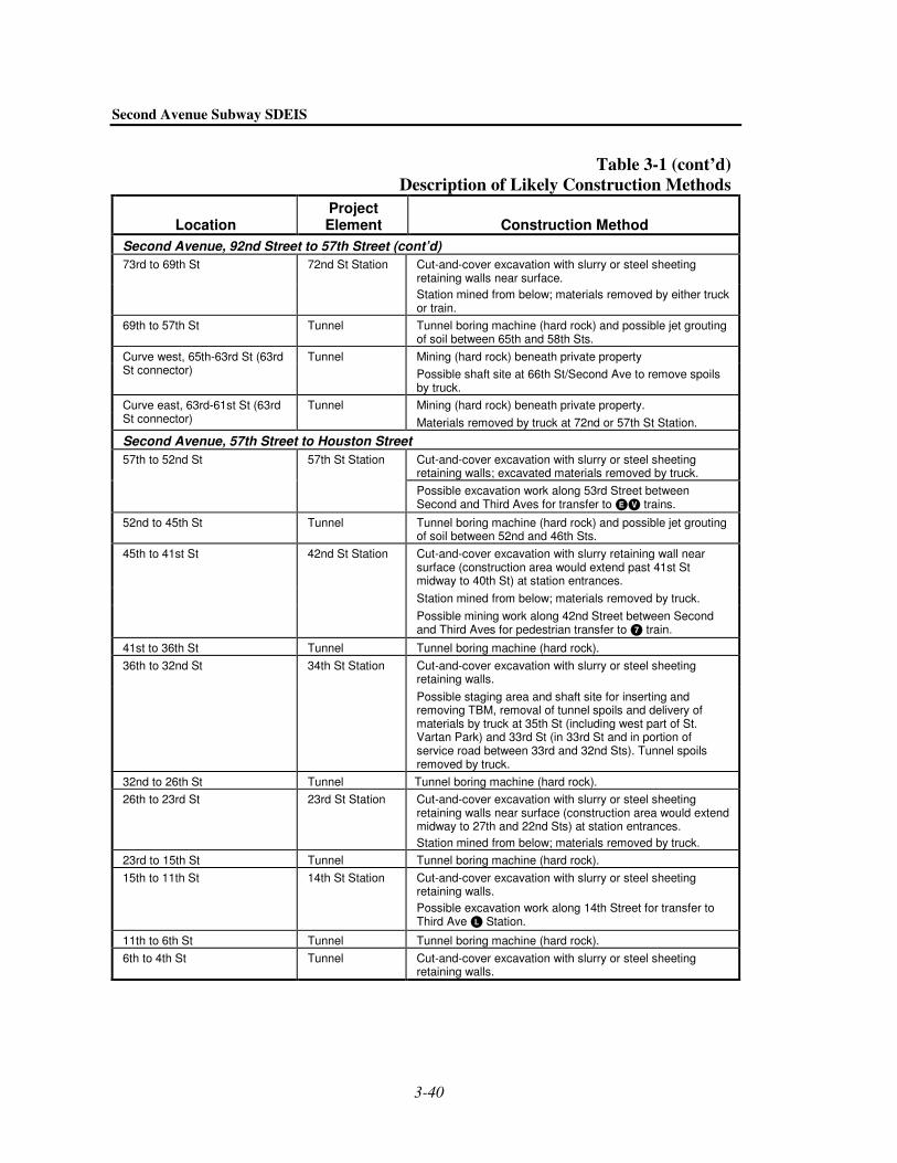
Second Avenue Subway SDEIS
3-40
Table 3-1 (cont’d) Description of Likely Construction Methods
Location Project Element Construction Method
Second Avenue, 92nd Street to 57th Street (cont’d) 73rd to 69th St 72nd St Station Cut-and-cover excavation with slurry or steel sheeting
retaining walls near surface. Station mined from below; materials removed by either truck
or train. 69th to 57th St Tunnel Tunnel boring machine (hard rock) and possible jet grouting
of soil between 65th and 58th Sts. Mining (hard rock) beneath private property Curve west, 65th-63rd St (63rd
St connector) Tunnel
Possible shaft site at 66th St/Second Ave to remove spoils by truck. Mining (hard rock) beneath private property. Curve east, 63rd-61st St (63rd
St connector) Tunnel
Materials removed by truck at 72nd or 57th St Station.
Second Avenue, 57th Street to Houston Street Cut-and-cover excavation with slurry or steel sheeting retaining walls; excavated materials removed by truck.
57th to 52nd St 57th St Station
Possible excavation work along 53rd Street between Second and Third Aves for transfer to � � trains.
52nd to 45th St Tunnel Tunnel boring machine (hard rock) and possible jet grouting of soil between 52nd and 46th Sts. Cut-and-cover excavation with slurry retaining wall near surface (construction area would extend past 41st St midway to 40th St) at station entrances. Station mined from below; materials removed by truck.
45th to 41st St 42nd St Station
Possible mining work along 42nd Street between Second and Third Aves for pedestrian transfer to � train.
41st to 36th St Tunnel Tunnel boring machine (hard rock). Cut-and-cover excavation with slurry or steel sheeting retaining walls.
36th to 32nd St 34th St Station
Possible staging area and shaft site for inserting and removing TBM, removal of tunnel spoils and delivery of materials by truck at 35th St (including west part of St. Vartan Park) and 33rd St (in 33rd St and in portion of service road between 33rd and 32nd Sts). Tunnel spoils removed by truck.
32nd to 26th St Tunnel Tunnel boring machine (hard rock). 26th to 23rd St 23rd St Station Cut-and-cover excavation with slurry or steel sheeting
retaining walls near surface (construction area would extend midway to 27th and 22nd Sts) at station entrances. Station mined from below; materials removed by truck.
23rd to 15th St Tunnel Tunnel boring machine (hard rock). 15th to 11th St 14th St Station Cut-and-cover excavation with slurry or steel sheeting
retaining walls. Possible excavation work along 14th Street for transfer to Third Ave Station.
11th to 6th St Tunnel Tunnel boring machine (hard rock). 6th to 4th St Tunnel Cut-and-cover excavation with slurry or steel sheeting
retaining walls.

Chapter 3: Description of Construction Methods and Activities
3-41
Table 3-1 (cont’d) Description of Likely Construction Methods
Location Project Element Construction Method
Second Avenue, 57th Street to Houston Street (cont’d) Cut-and-cover excavation with slurry or steel sheeting retaining walls.
4th to Houston St Houston St Station
Possible shaft site at Houston St for inserting/removing boring machines, removal of tunnel spoils, and delivery of materials by truck.
Houston Street to Chatham Square For Shallow Chrystie Option (No Longer Under Consideration) Cut-and-cover excavation with slurry or steel sheeting retaining walls and underpinning. Alongside existing subway tunnel on both sides of Chrystie St, extending into Sara D. Roosevelt Park.
For Deep Chrystie Option Soft ground tunnel boring under existing subway tunnel.
Houston to Delancey St Tunnel
For Forsyth St Option Soft ground tunnel boring. Curve under Sara D. Roosevelt Park.
Delancey to Hester St Grand St Station For Shallow Chrystie Option (No Longer Under Consideration) Cut-and-cover excavation with slurry or steel sheeting retaining walls. Alongside existing subway tunnel on both sides of Chrystie St, extending into Sara D. Roosevelt Park.
For Deep Chrystie Option Mining, cut-and-cover excavation, and underpinning beneath existing Grand Street Station extending into Sara D. Roosevelt Park.
For Forsyth St Option Cut-and-cover excavation with slurry or steel sheeting retaining walls under Forsyth St extending into Sara D. Roosevelt Park. Reconstruct existing Grand Street Station using cut-and-cover techniques extending into Sara D. Roosevelt Park.
Hester to Canal St Tunnel For Shallow Chrystie Option (No Longer Under Consideration) Cut-and-cover excavation with slurry or steel sheeting retaining walls extending into Sara D. Roosevelt Park.
For Deep Chrystie Option Soft ground tunnel boring.
For Forsyth St Option Soft ground tunnel boring; curve under Sara D. Roosevelt Park. For Shallow Chrystie Option (No Longer Under Consideration) Existing tunnel segment—no new excavation.
Canal St to Chatham Square (Pell St)
Tunnel
For Deep Chrystie or Forsyth Street Options Soft ground tunnel boring beneath existing tunnel.
St. James Pl, Pearl St, and Water St: Chatham Square to Southern Terminus Pell to Madison St Chatham Square
Station Cut-and-cover excavation with slurry or steel sheeting retaining walls.

Second Avenue Subway SDEIS
3-42
Table 3-1 (cont’d) Description of Likely Construction Methods
Location Project Element Construction Method
St. James Pl, Pearl St, and Water St: Chatham Square to Southern Terminus (cont’d) For Shallow Chrystie Option (No Longer Under Consideration) Cut-and-cover excavation with slurry or steel sheeting retaining walls.
Madison to Dover St Tunnel
For Deep Chrystie or Forsyth Street Options Soft ground tunnel boring through soil.
Dover to John St Seaport Station Cut-and-cover excavation with slurry or steel sheeting retaining walls.
John to Wall St Tunnel Cut-and-cover excavation with slurry or steel sheeting retaining walls.
Wall St to Coenties Slip Hanover Square Station
Cut-and-cover excavation with slurry or steel sheeting retaining walls. Possible barge site at Pier 6; materials removed on Water Street near Coenties Slip and conveyed or trucked along Gouverneur Lane or Old Slip.
different construction contractors are working in each area. At this time, it is not anticipated that adjacent stations would be constructed simultaneously, to avoid disturbing a large area at once. However, with the Shallow Chrystie Street Option, stations might have been constructed simultaneously with the required cut-and-cover construction.
In all, the total quantity of spoils that would need to be removed from the northern section is ap-proximately 1.25 million cubic yards. Construction of the northern section would take approxi-mately 10 years. In the southern section, the total quantity of spoils that would need to be removed from the southern section is approximately 1.75 million cubic yards. Depending on the spoils removal option selected, construction of the southern section could range from 10 to 16 years.
CONSTRUCTION SCHEDULE AND OPERATIONS
Tunnel construction activities (excavation and tunnel lining) for the options outlined above are expected to take between 5 to 8 years, with an additional 5 to 8 years for the rest of the subway’s construction, including station build-out and finishing. These projected timeframes are contin-gent on the extent of available funding and on whether concurrent tunneling can occur in several locations simultaneously. For estimating and scheduling purposes, it has been assumed that the TBM and EPBM operations would occur 6 days a week for 24 hours per day.
E. OTHER CONSTRUCTION ELEMENTS In addition to the work required to construct new tunnels and stations described in detail above, the project would also require some other construction work related to connections to existing stations and to the new storage yards that would be required for the Second Avenue Subway trains.

Chapter 3: Description of Construction Methods and Activities
3-43
CONNECTIONS TO EXISTING STATIONS
As described in Chapter 2, “Project Alternatives,” the project would require some construction at existing stations where connections or transfers are proposed. Connection work could require disruptions to existing stations. Transfers would consist of underground passageways connecting the new and existing lines. Construction of the transfer tunnels would most likely be done by a combination of cut-and-cover and shielded mining during construction in stations.
This work would be as follows:
• Transfer to the Metro-North Railroad Station at 125th Street would be created at the western end of the new 125th Street Station. Stairs, escalators, and an elevator from the new subway station would lead directly to the Metro-North station. Existing staircases at the Metro-North station could be affected for short periods during construction.
• The transfer to the Lexington Avenue Line � � at 125th Street would be built beneath the existing Lexington Avenue Station structure through a new lower-level mezzanine that would connect to the existing downtown platform level and the direct connection to the up-per mezzanine stairways would be reconfigured. Within the station, some disruptions would occur for existing passengers as extensive construction work would occur within the station. This work would be conducted primarily during late nights and weekends for up to a year.
• The Second Avenue Subway’s Broadway Line service would use the existing Lexington Avenue/63rd Street Station. Portions of the existing Lexington Avenue/63rd Street Station must be completed before the station can serve the proposed new subway service. The station is structurally complete, but the two platform levels are currently only finished on the south side, and are separated from the unfinished portions by a partition. Most of the finish work for the north side of the platform, serving Tracks 3 and 4, can be done with the partition in place without affecting current operations. After the work behind the partition is completed, temporary barriers would be placed to allow the remaining center portions of the platform to be completed with only minor inconvenience to passengers.
The Third Avenue entrance at the Lexington Avenue/63rd Street Station is also structurally complete but unfinished. It does not include wall and floor finishes, lighting, signs, escala-tors, etc. At the time of the Lexington Avenue/63rd Street Station’s original construction in the early 1980s, street-level entrances were built within the sidewalk area at the northeast, northwest and southwest corners of Third Avenue and 63rd Street. In addition, another entrance on the southeast corner was designed to come up into private property. These have been temporarily sealed with a concrete slab, and remain available. The Second Avenue Subway could use some or all of these entrances from the Third Avenue end of the station with minimal new construction. Some minor disruption to sidewalk areas near Third Avenue would occur when the new entrances are created.
• The connection between the south end of the new 57th Street Station on the Second Avenue Subway and the Lexington Avenue/53rd Street Station’s � � lines would be constructed using either cut-and-cover or shielded mining techniques. Some construction would also be required within the existing station.
• The pedestrian tunnel connecting the Second Avenue Subway station at 42nd Street with the 42nd Street/Grand Central Terminal Station on the Flushing Line (�) would require con-struction along 42nd Street between Second Avenue and the west side of Third Avenue. This new approximately 1,000-foot tunnel would be mined beneath 42nd Street, requiring slow

Second Avenue Subway SDEIS
3-44
and difficult construction. Significant construction could be needed within the existing � station to provide adequate capacity and ADA access for this transfer.
• The connection to the 14th Street Station on the Canarsie Line () currently under consid-eration would require a 200-foot-long passageway between Second and Third Avenues.
• The design of the connection at Houston Street to the � trains on the Sixth Avenue Line would vary depending on whether the Deep Chrystie Option or the Forsyth Street Option is selected south of Houston Street. In either case, some construction activity at the existing station would be required to make the connection.
• The transfer to the Grand Street Station on the �� Line would again depend on whether the Deep Chrystie Option or the Forsyth Street Option is selected. With the Deep Chrystie Option, a mezzanine below the existing station would permit a vertical transfer to the new Second Avenue Subway platform. With the Forsyth Street Option, a passageway would run along Grand Street between Forsyth and Chrystie Streets. The Shallow Chrystie Option, which is no longer under consideration, would widen the Grand Street Station for a cross-platform transfer.
YARDS AND MAINTENANCE FACILITIES
In addition to work on station and tunnel infrastructure, construction of maintenance support facilities would be required for the new Second Avenue Subway. Several alternatives for train storage and for inspection and maintenance are under consideration. Construction work for these alternatives is described below.
NEW 129TH STREET STORAGE TRACKS AND 125TH STREET STORAGE TRACKS
New underground storage tracks are planned both north of 125th Street on Second Avenue and west of the new 125th Street Station at Park Avenue. These tracks would be constructed using a combination of cut-and-cover and shielded mining techniques. During construction, it would be necessary to close portions of 125th Street and Second Avenue near some of the historic Triborough Bridge ramps. As discussed in Chapter 5, “Transportation,” NYCT would work with MTA Bridges and Tunnels to minimize traffic impacts in this area, and to protect the historic resources.
NEW STORAGE YARD AT CONEY ISLAND YARD
Construction of a new single-track bridge over the Coney Island Creek would be required to connect any potential new yard adjacent to the existing Coney Island Yard. This would involve construction of new abutments and placement of a new span, and probable pile placement within Coney Island Creek. It is possible that some repairs to the existing riprap (stone embankment) bulkhead would also be needed to support the upland activities. This could occur either by re-armoring the slope with stones of a suitable size, or potentially installing a new bulkhead. Within the new yard site, construction would be limited to surface construction, including grading, track bed, traction power equipment, and signals.
ALTERATIONS AT OTHER SUBWAY YARDS
If the 36th-38th Street Yard were used to provide storage for Second Avenue trains, some im-provements would be required within the existing yard. Construction on the yard would be

Chapter 3: Description of Construction Methods and Activities
3-45
limited largely to surface disturbance, although a retaining wall on the south side of the property would need to be partially reconfigured.
At Concourse Yard, some tracks would be reconfigured and a new maintenance shop would be constructed to replace (and double in size) the existing facility. This new facility could be con-structed in the same location as the existing shop, necessitating disruptions to existing operations at Concourse Yard. During Preliminary Engineering for the Second Avenue Subway, the feasibility of removing the shop from service during construction of the new shop will be investigated, should this Concourse Yard option be selected for advancement. This new, larger shop would extend over existing yard tracks, also changing the train operations at Concourse Yard. Alternatively, a new shop could be constructed at Concourse Yard in an area now occupied by storage tracks, which would allow the existing shop to remain in service during construction of the new shop. This would, however, seriously limit storage capacity during construction until new storage could be constructed in the site of the existing shop. These issues will be explored in further detail if the Concourse Yard shop is selected for further study.
At 207th Street Yard, construction would occur within the existing maintenance shop, to expand its capacity. The 207th Street maintenance shop is a six-track shop that serves 215 cars of the � line. This shop is scheduled for reconstruction starting in 2007, and the adjacent overhaul shop is scheduled to be rehabilitated starting in 2003. A design for this expansion will be developed during the Preliminary Engineering process.
F. ACCESS LIMITATIONS DURING CONSTRUCTION During construction, it would be necessary to limit or curtail vehicular and pedestrian access in certain areas to ensure public safety and to accommodate the variety of machinery, storage areas, and construction activities that would occur. Generally, the method of construction would deter-mine the extent of access limitations that would occur along the various lengths of the alignment. In most cases, access would be provided to residential and commercial buildings, including retail businesses, at all times. However, in limited areas, it would be necessary to restrict access to buildings for periods ranging from several hours to up to 6 months.
The need to close traffic lanes and sidewalk areas at various times will result in temporary re-strictions to vehicular and pedestrian access in certain areas. The extent of these disruptions will depend on the type of construction required. For example, in areas where construction would oc-cur entirely below ground, little, if any, disruptions to pedestrian or vehicular access would oc-cur. In contrast, in areas where slurry wall and cut-and-cover construction is necessary to build the tunnels or stations, traffic lane closures or sidewalk narrowing could last from less than 6 months to approximately 4 years. (The longer durations would generally occur where stations would be constructed.) Sidewalk narrowings in limited areas, such as near shaft sites, could last up to 10 years. During this time, vehicles would be prohibited from stopping, standing, or parking alongside construction sites, and bus stops located within affected areas would be temporarily relocated. Possible reductions in sidewalk width could also occur, as could some minor detours around construction equipment. Except in the very limited cases described below, it is expected that pedestrian access to buildings would be maintained at all times. However, drop-offs and deliveries for both residences and businesses would have to be relocated to nearby points outside of the construction areas.
At the various shaft sites and spoils removal areas, access disruptions would be similar to those discussed above for cut-and-cover construction, though they could be longer in certain cases—

Second Avenue Subway SDEIS
3-46
chiefly, at the spoils removal areas in the 90s, 30s, the Houston Street vicinity, and on Water Street near Coenties Slip. Pedestrian access to some residential buildings in these areas (Second Avenue from 99th to approximately 92nd Street, 36th to 32nd Streets, from 6th to Houston Streets, and on Water Street between Wall Street and Coenties Slip) might have to be provided through protected portions of the construction zones and on temporary pedestrian walkways. Vehicular access to these areas would also be restricted for longer durations than with typical cut-and-cover activities.
In some cases where tunneling beneath buildings, underpinning, and other ground improvement techniques would be needed (see the list of affected areas under the “Underpinning” section dis-cussed above), construction might need to occur within basements of certain affected buildings. Though access to the buildings above would generally be provided, access to some basement areas might be temporarily restricted. In such areas, it is not anticipated that NYCT will need to acquire buildings or permanently displace residents and businesses from buildings adjacent to the construction work. However, in some limited locations, businesses and residents may have to relocate for up to four months due to safety concerns or significant access restrictions. In such instances, it is possible that some businesses and residents would chose not return to their former building locations, and that some businesses could be displaced permanently. NYCT would make extensive efforts to avoid such displacement. Please see Chapter 8, “Displacement and Relocation,” for more information.
Finally, with the Shallow Chrystie Option, along Chrystie Street from Houston Street to Canal Street, access limitations would be more restrictive. In this option, it is possible that access to residential buildings in this area could be interrupted for up to 4 weeks at a time. While efforts would be made to maintain access to these buildings, residents might need to relocate temporarily if this could not be achieved. Chapter 8 discusses this issue in more detail. Businesses in this area would also be affected, as pedestrian activity would be reduced for 1 to 2 weeks at a time in any given area. Because of these access disruptions, among other factors, the Shallow Chrystie Option is no longer under consideration.
As described in other chapters of this SDEIS, a variety of measures would be taken to minimize the effects of access restrictions on residential and commercial properties. For example, in each zone where heavy construction would occur (such as at station locations, cut and cover tunnel construction areas, and shaft sites), a detailed analysis would be conducted prior to any construction to consider the access needs of the affected properties, and a plan would be prepared that responds to the specific needs of the individual properties to the degree possible. At this early stage in project design, it is not feasible to provide specific proposals for each construction zone, but it should be understood that a number of elements will be considered.
First, uninterrupted pedestrian access would be provided to nearly all properties throughout the construction period via safe and protected routes. Methods for providing access would generally focus on keeping the property’s normal principal entrance in service during construction. In in-stances where buildings have workable alternative entrances that can provide safe and functional service to pedestrians, these secondary entrances might be used at certain stages of the construction period. If needed, special signage would be provided to direct pedestrians to buildings and businesses within the construction zone. NYCT and its contractors will adhere to all applicable safety codes and regulations governing pedestrian facilities in construction zones.
Second, because vehicular access to curb areas in front of businesses along the alignment would be interrupted in the construction zones, consideration regarding the effects of these interrup-tions will be thoroughly evaluated in the analysis on access needs, and measures would be

Chapter 3: Description of Construction Methods and Activities
3-47
employed to reduce such disturbances. These may include creation of new drop-off and loading areas on nearby cross streets for use by residents and businesses, and special signage if needed. The potential to employ alternative entrances would also be considered in the analysis.
Third, the access evaluation plan and the resulting mitigation program would be developed in close consultation and coordination with affected residents and businesses. In addition, as con-struction progresses, if any specific issues arise that require modifications to the access system, NYCT and its contractors would continue to communicate with local residents and businesses to ensure that concerns are addressed promptly.
G. IMPROVEMENTS FOLLOWING CONSTRUCTION When construction of the new subway is complete, all streets, sidewalks, parks, and other areas that were disturbed by construction would be returned to normal or improved condition. As work at a particular station or excavation site is completed, streets and sidewalks would be reconstructed and repaved. This reconstruction would be conducted in coordination with NYCDOT and any other relevant city agencies. As part of this effort, street furniture would also be replaced and updated in coordination with NYCDOT.
All parks used during construction would be restored following completion of construction activities in the park. This work would be conducted in consultation with the New York City Department of Parks and Recreation (NYCDPR). NYCT would work with NYCDPR to design and fully restore all affected parks after subway construction in the area of each park is complete. The replacement amenities would be designed to meet current recreational demands in the area. Any trees in parks and along streets that had to be removed during construction would be replaced, in consultation with NYCDPR. NYCT would consult with NYCDPR regarding identifying tree replacement species, with consideration of whether maturation height would be affected by subway construction. NYCT would make every practicable effort to ensure that future tree replacement would not be constrained by subsurface or surface subway elements or activities.
As described earlier, should the 129th Street barge site be used for to remove spoils from Manhattan, the existing bulkhead would be repaired or replaced. Either would result in a permanent improvement. Similarly, if the Coney Island Yard expansion site is used for train storage, the existing riprap (stone embankment) bulkhead might also be repaired. If bulkhead improvements at any of these locations are made during construction of the project, they would remain in place once the project is completed, resulting in a permanent improvement.
At the barge sites at 129th Street and Pier 6, the barges and other equipment would be removed after their use is no longer necessary. However, these facilities could potentially be retained, if appropriate for another public use.
Overall, once the subway construction is complete, all construction sites would be fully restored and those improvements would remain in place. The subway stations, vent structures, and other subway facilities would become a permanent part of the city’s infrastructure, in combination with the other elements of the urban environment. �