chapter 3: modeling concurrent functionality · 2019-01-04 · these operators work on types...
TRANSCRIPT

Chapter 3: Modeling ConcurrentFunctionality
This chapter presents a set of built-in operators that will allow logic to be modeled within the VHDLarchitecture. This chapter then presents a series of combinational logic model examples.
Learning Outcomes—After completing this chapter, you will be able to:
3.1 Describe the various built-in operators within VHDL.3.2 Design a VHDL model for a combinational logic circuit using concurrent signal
assignments and logical operators.3.3 Design a VHDL model for a combinational logic circuit using conditional signal
assignments.3.4 Design a VHDL model for a combinational logic circuit using selected signal assignments.3.5 Design a VHDL model for a combinational logic circuit that contains delay.
3.1 VHDL Operators
There are a variety of pre-defined operators in the IEEE standard package. It is important to notethat operators are defined to work on specific data types and that not all operators are synthesizable. It isalso important to remember that VHDL is a hardware description language, not a programming lan-guage. In a programming language, the lines of code are executed sequentially as they appear in thesource file. In VHDL, the lines of code represent the behavior of real hardware. As a result, all signalassignments are by default executed concurrently unless specifically noted otherwise. All operations inVHDL must be on like types, and the result must be assigned to the same type as the operation inputs.
3.1.1 Assignment Operator
VHDL uses <¼ for all signal assignments and :¼ for all variable and initialization assignments.These assignment operators work on all data types. The target of the assignment goes on the left ofthese operators and the input arguments go on the right.
Example:
F1 <¼ A; -- F1 and A must be the same size and typeF2 <¼ ‘0’; -- F2 is type bit in this exampleF3 <¼ “0000”; -- F3 is type bit_vector(3 downto 0) in this exampleF4 <¼ “hello”; -- F4 is type string in this exampleF5 <¼ 3.14; -- F5 is type real in this exampleF6 <¼ x”1A”; -- F6 is type bit_vector(7 downto 0), x”1A” is in HEX
# Springer Nature Switzerland AG 2019B. J. LaMeres, Quick Start Guide to VHDL, https://doi.org/10.1007/978-3-030-04516-6_3
21

3.1.2 Logical Operators
VHDL contains the following logical operators:
Operator Operation
not Logical negation
and Logical AND
nand Logical NAND
or Logical OR
nor Logical NOR
xor Logical Exclusive-OR
xnor Logical Exclusive-NOR
These operators work on types bit, bit_vector, and boolean. For operations on the type bit_vector,the input vectors must be the same size and will take place in a bit-wise fashion. For example, if two 8-bitbuses called BusA and BusB were AND’d together, BusA(0) would be individually AND’d with BusB(0),BusA(1) would be individually AND’d with BusB(1), etc. The not operator is a unary operation (i.e., itoperates on a single input), and the keyword is put before the signal being operated on. All otheroperators have two or more inputs and are placed in-between the input names.
Example:
F1 <¼ not A;F2 <¼ B and C;
The order of precedence in VHDL is different from in Boolean algebra. The NOToperator is a higherpriority than all other operators. All other logical operators have the same priority and have no inherentprecedence. This means that in VHDL, the AND operator will not precede the OR operation as it does inBoolean algebra. Parentheses are used to explicitly describe precedence. If operators are used thathave the same priority and parentheses are not provided, then the operations will take place on thesignals listed first moving left to right in the signal assignment. The following are examples on how to usethese operators:
Example:
F3 <¼ not D nand E; -- D will be complemented first, the result-- will then be NAND’d with E, then the-- result will be assigned to F3
F4 <¼ not (F or G); -- the parentheses take precedence so-- F will be OR’d with G first, then-- complemented, and then assigned to F4.
F5 <¼ H nor I nor J; -- logic operations can have any number of-- inputs.
F6 <¼ K xor L xnor M; -- XOR and XNOR have the same priority so with-- no parentheses given, the logic operations-- will take place on the signals from-- left to right. K will be XOR’d with L first,-- then the result will be XNOR’d with M.
22 • Chapter 3: Modeling Concurrent Functionality

3.1.3 Numerical Operators
VHDL contains the following numerical operators:
Operator Operation
+ Addition
- Subtraction
* Multiplication
/ Division
mod Modulus
rem Remainder
abs Absolute value
** Exponential
These operators work on types integer and real. Note that the default VHDL standard does notsupport numerical operators on types bit and bit_vector.
3.1.4 Relational Operators
VHDL contains the following relational operators. These operators compare two inputs of the sametype and return the type Boolean (i.e., true or false).
Operator Returns true if the comparison is:
¼ Equal
/¼ Not equal
< Less than
<¼ Less than or equal
> Greater than
>¼ Greater than or equal
3.1.5 Shift Operators
VHDL contains the following shift operators. These operators work on vector types bit_vector andstring.
Operator Operation
sll Shift left logical
srl Shift right logical
sla Shift left arithmetic
sra Shift right arithmetic
rol Rotate left
ror Rotate right
The syntax for using a shift operation is to provide the name of the vector followed by the desiredshift operator, followed by an integer indicating how many shift operations to perform. The target of theassignment must be the same type and size as the input.
Example:
A <¼ B srl 3; -- A is assigned the result of a logical shift-- right 3 times on B.
3.1 VHDL Operators • 23

3.1.6 Concatenation Operator
In VHDL the& is used to concatenate multiple signals. The target of this operation must be the samesize of the sum of the sizes of the input arguments.
Example:
Bus1 <¼ “11” & “00”; -- Bus1 must be 4-bits and will be assigned-- the value “1100”
Bus2 <¼ BusA & BusB; -- If BusA and BusB are 4-bits, then Bus2-- must be 8-bits.
Bus3 <¼ ‘0’ & BusA; -- This attaches a leading ‘0’ to BusA. Bus3-- must be 5-bits
CONCEPT CHECK
CC3.1 Do all of the operators provided in the standard package work for all data types providedin the same package?
(A) Yes. Since both the operators and data types are in the same package, theyall work together.
(B) No. Each operator only works on specific data types. It is up to the designer toknow what types the operator work with.
3.2 Concurrent Signal Assignments with Logical Operators
Concurrent signal assignments are accomplished by simply using the <¼ operator after the beginstatement in the architecture. Each individual assignment will be executed concurrently and synthesizedas separate logic circuits. Consider the following example:
Example:
X <¼ A;Y <¼ B;Z <¼ C;
When simulated, these three lines of VHDL will make three separate signal assignments at theexact same time. This is different from a programming language that will first assign A to X, then B to Y,and finally C to Z. In VHDL this functionality is identical to three separate wires. This description will bedirectly synthesized into three separate wires.
Below is another example of how concurrent signal assignments in VHDL differ from a sequentiallyexecuted programming language:
Example:
A <¼ B;B <¼ C;
In a VHDL simulation, the signal assignments of C to B and B to A will take place at the same time;however, during synthesis, the signal B will be eliminated from the design since this functionality
24 • Chapter 3: Modeling Concurrent Functionality
describes two wires in series. Automated synthesis tools will eliminate this unnecessary signal name.This is not the same functionality that would result if this example was implemented as a sequentiallyexecuted computer program. A computer program would execute the assignment of B to A first and thenassign the value of C to B second. In this way, B represents a storage element that is passed to A beforeit is updated with C.
Each of the logical operators described in Sect. 3.1.2 can be used in conjunction with concurrentsignal assignments to create individual combinational logic circuits.
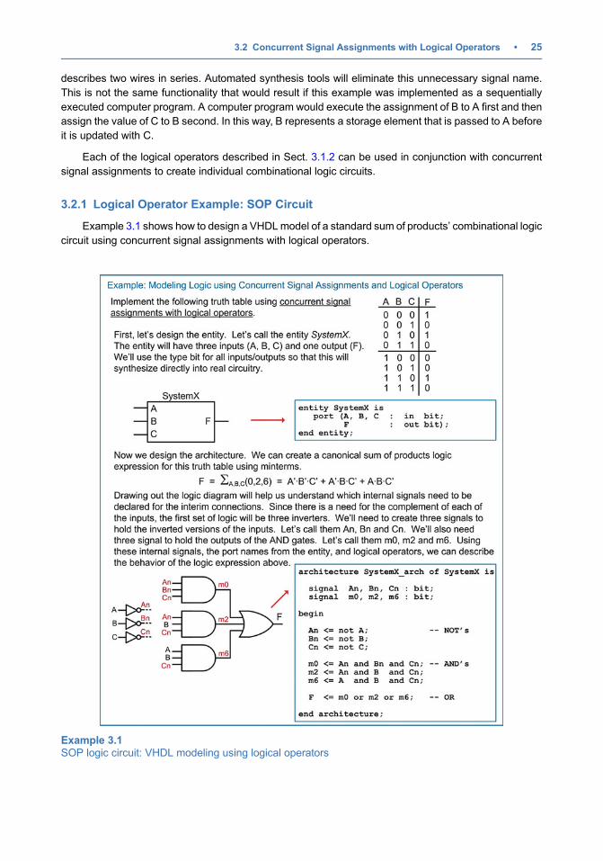
3.2.1 Logical Operator Example: SOP Circuit
Example 3.1 shows how to design a VHDLmodel of a standard sum of products’ combinational logiccircuit using concurrent signal assignments with logical operators.
Example 3.1SOP logic circuit: VHDL modeling using logical operators
3.2 Concurrent Signal Assignments with Logical Operators • 25
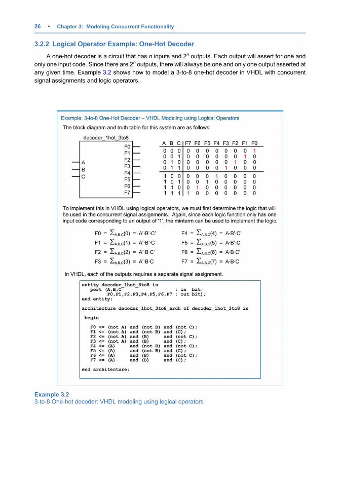
3.2.2 Logical Operator Example: One-Hot Decoder
A one-hot decoder is a circuit that has n inputs and 2n outputs. Each output will assert for one andonly one input code. Since there are 2n outputs, there will always be one and only one output asserted atany given time. Example 3.2 shows how to model a 3-to-8 one-hot decoder in VHDL with concurrentsignal assignments and logic operators.
Example 3.23-to-8 One-hot decoder: VHDL modeling using logical operators
26 • Chapter 3: Modeling Concurrent Functionality
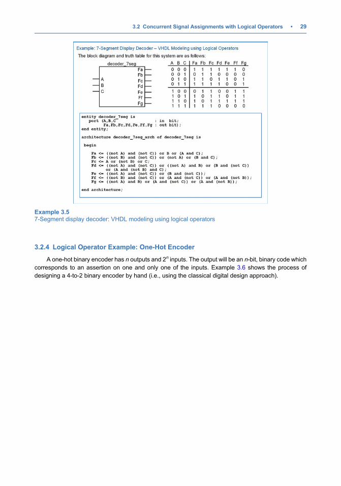
3.2.3 Logical Operator Example: 7-Segment Display Decoder
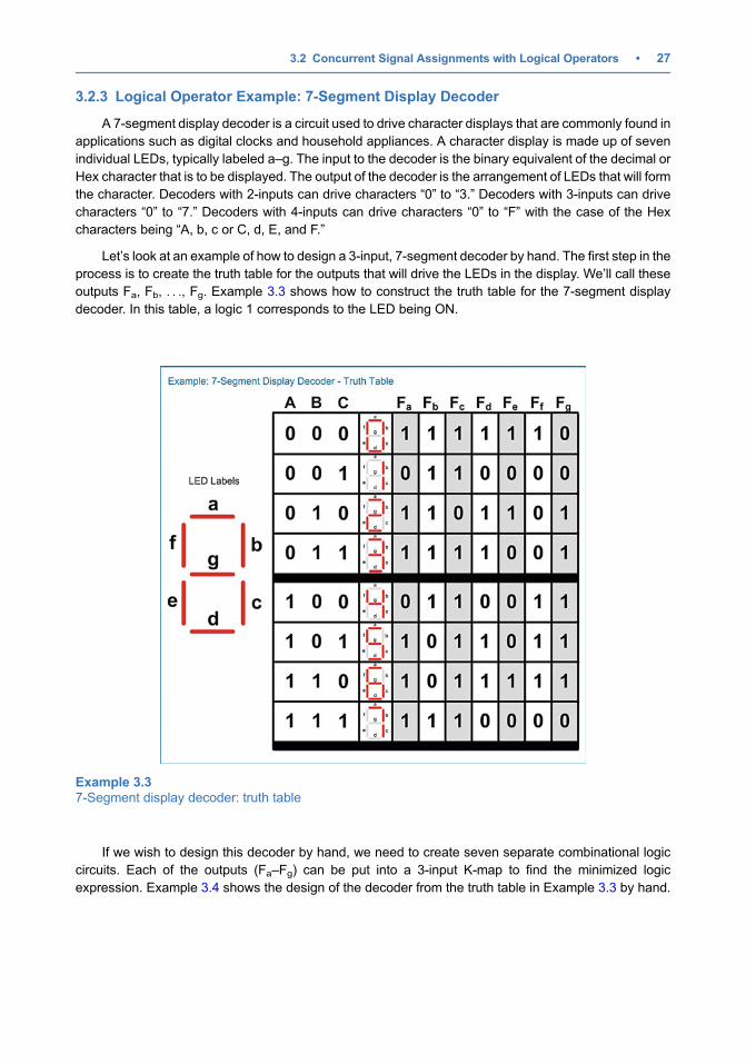
A 7-segment display decoder is a circuit used to drive character displays that are commonly found inapplications such as digital clocks and household appliances. A character display is made up of sevenindividual LEDs, typically labeled a–g. The input to the decoder is the binary equivalent of the decimal orHex character that is to be displayed. The output of the decoder is the arrangement of LEDs that will formthe character. Decoders with 2-inputs can drive characters “0” to “3.” Decoders with 3-inputs can drivecharacters “0” to “7.” Decoders with 4-inputs can drive characters “0” to “F” with the case of the Hexcharacters being “A, b, c or C, d, E, and F.”
Let’s look at an example of how to design a 3-input, 7-segment decoder by hand. The first step in theprocess is to create the truth table for the outputs that will drive the LEDs in the display. We’ll call theseoutputs Fa, Fb, . . ., Fg. Example 3.3 shows how to construct the truth table for the 7-segment displaydecoder. In this table, a logic 1 corresponds to the LED being ON.
If we wish to design this decoder by hand, we need to create seven separate combinational logiccircuits. Each of the outputs (Fa–Fg) can be put into a 3-input K-map to find the minimized logicexpression. Example 3.4 shows the design of the decoder from the truth table in Example 3.3 by hand.
Example 3.37-Segment display decoder: truth table
3.2 Concurrent Signal Assignments with Logical Operators • 27
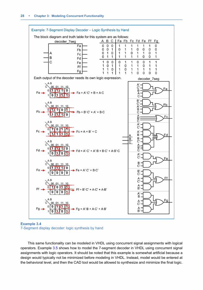
This same functionality can be modeled in VHDL using concurrent signal assignments with logicaloperators. Example 3.5 shows how to model the 7-segment decoder in VHDL using concurrent signalassignments with logic operators. It should be noted that this example is somewhat artificial because adesign would typically not be minimized before modeling in VHDL. Instead, model would be entered atthe behavioral level, and then the CAD tool would be allowed to synthesize and minimize the final logic.
Example 3.47-Segment display decoder: logic synthesis by hand
28 • Chapter 3: Modeling Concurrent Functionality
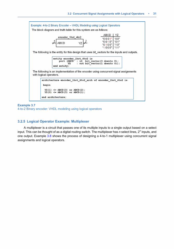
3.2.4 Logical Operator Example: One-Hot Encoder
A one-hot binary encoder has n outputs and 2n inputs. The output will be an n-bit, binary code whichcorresponds to an assertion on one and only one of the inputs. Example 3.6 shows the process ofdesigning a 4-to-2 binary encoder by hand (i.e., using the classical digital design approach).
Example 3.57-Segment display decoder: VHDL modeling using logical operators
3.2 Concurrent Signal Assignments with Logical Operators • 29

In VHDL this can be implemented directly using logical operators. Example 3.7 shows how to modelthe encoder in VHDL using concurrent signal assignments with logical operators.
Example 3.64-to-2 Binary encoder: logic synthesis by hand
30 • Chapter 3: Modeling Concurrent Functionality
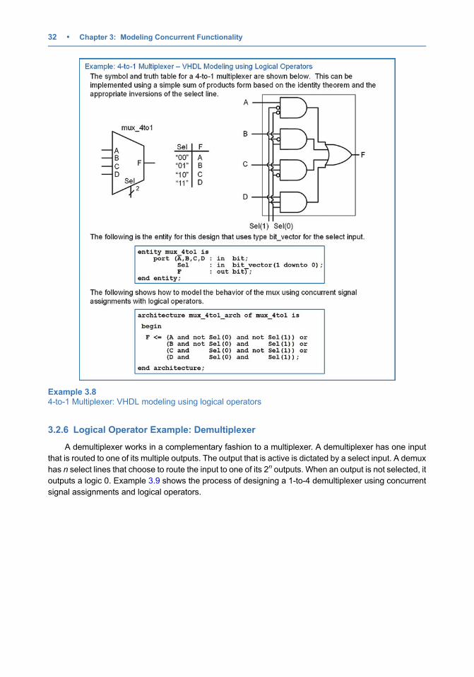
3.2.5 Logical Operator Example: Multiplexer
A multiplexer is a circuit that passes one of its multiple inputs to a single output based on a selectinput. This can be thought of as a digital routing switch. The multiplexer has n select lines, 2n inputs, andone output. Example 3.8 shows the process of designing a 4-to-1 multiplexer using concurrent signalassignments and logical operators.
Example 3.74-to-2 Binary encoder: VHDL modeling using logical operators
3.2 Concurrent Signal Assignments with Logical Operators • 31
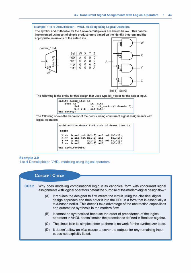
3.2.6 Logical Operator Example: Demultiplexer
A demultiplexer works in a complementary fashion to a multiplexer. A demultiplexer has one inputthat is routed to one of its multiple outputs. The output that is active is dictated by a select input. A demuxhas n select lines that choose to route the input to one of its 2n outputs. When an output is not selected, itoutputs a logic 0. Example 3.9 shows the process of designing a 1-to-4 demultiplexer using concurrentsignal assignments and logical operators.
Example 3.84-to-1 Multiplexer: VHDL modeling using logical operators
32 • Chapter 3: Modeling Concurrent Functionality
CONCEPT CHECK
CC3.2 Why does modeling combinational logic in its canonical form with concurrent signalassignments with logical operators defeat the purpose of themodern digital design flow?
(A) It requires the designer to first create the circuit using the classical digitaldesign approach and then enter it into the HDL in a form that is essentially atext-based netlist. This doesn’t take advantage of the abstraction capabilitiesand automated synthesis in the modern flow.
(B) It cannot be synthesized because the order of precedence of the logicaloperators in VHDL doesn’t match the precedence defined in Boolean algebra.
(C) The circuit is in its simplest form so there is no work for the synthesizer to do.
(D) It doesn’t allow an else clause to cover the outputs for any remaining inputcodes not explicitly listed.
Example 3.91-to-4 Demultiplexer: VHDL modeling using logical operators
3.2 Concurrent Signal Assignments with Logical Operators • 33

3.3 Conditional Signal Assignments
Logical operators are good for describing the behavior of small circuits; however, in the priorexample, we still needed to create the canonical or minimal sum of products logic expression by handbefore describing the functionality in VHDL. The true power of an HDL is when the behavior of the systemcan be described fully without requiring any hand design. A conditional signal assignment allows us todescribe a concurrent signal assignment using Boolean conditions that effect the values of the result. In aconditional signal assignment, the keyword when is used to describe the signal assignment for aparticular Boolean condition. The keyword else is used to describe the signal assignments for anyother conditions. Multiple Boolean conditions can be used to fully describe the output of the circuit underall input conditions. Logical operators can also be used in the Boolean conditions to create moresophisticated conditions. The Boolean conditions can be encompassed within parentheses for readabil-ity. The syntax for a conditional signal assignment is shown below.
signal_name <¼ expression_1 when condition_1 elseexpression_2 when condition_2 else
:expression_n;
Example:
F1 <¼ ‘0’ when A¼‘0’ else ‘1’;F2 <¼ ‘1’ when (A¼’0’ and B¼’1’) else ‘0’;F3 <¼ A when (C ¼ D) else B;
An important consideration of conditional signal assignments is that they are still executed concur-rently. Each assignment represents a separate, combinational logic circuit. In the above example, F1,F2, and F3 will be implemented as three separate, parallel circuits.
3.3.1 Conditional Signal Assignment Example: SOP Circuit
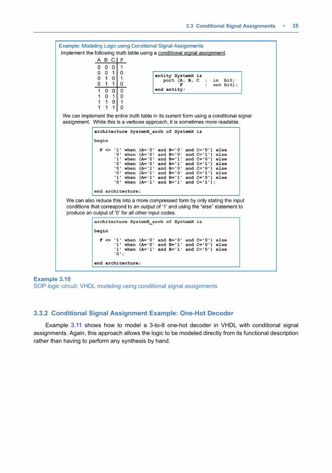
Example 3.10 shows how to design a VHDL model of a combinational logic circuit using conditionalsignal assignments. Note that this example uses the same truth table as in Example 3.1 to illustrate acomparison between approaches. This approach provides a model that can be created directly from thetruth table without needing to do any synthesis or minimization by hand.
34 • Chapter 3: Modeling Concurrent Functionality
3.3.2 Conditional Signal Assignment Example: One-Hot Decoder
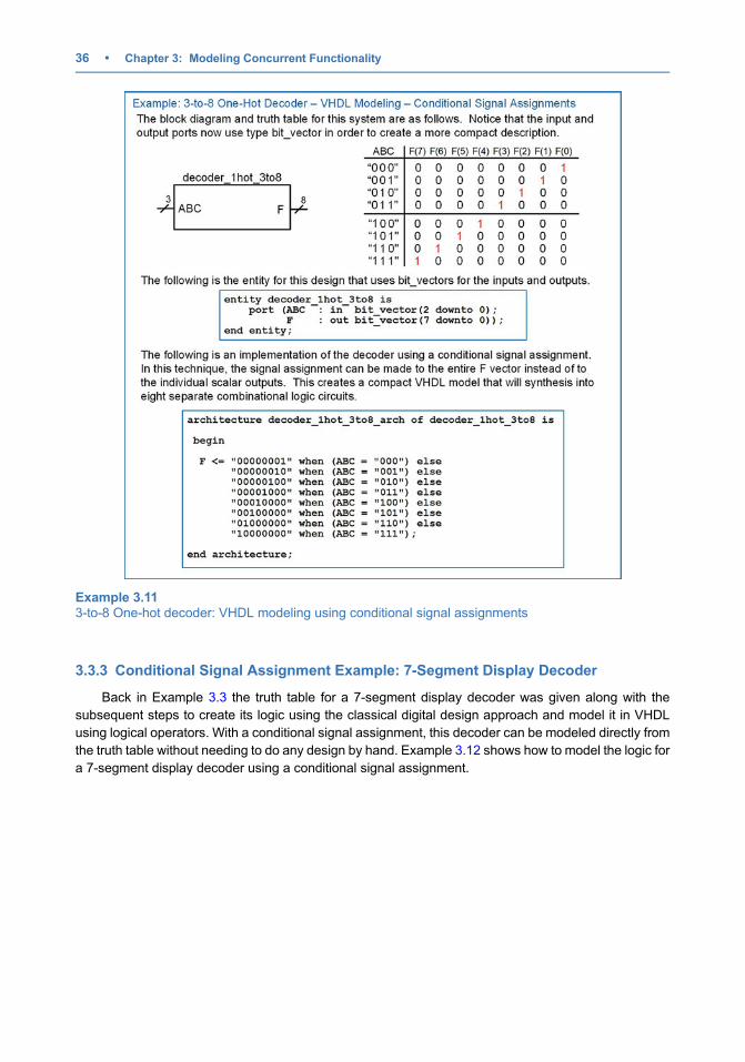
Example 3.11 shows how to model a 3-to-8 one-hot decoder in VHDL with conditional signalassignments. Again, this approach allows the logic to be modeled directly from its functional descriptionrather than having to perform any synthesis by hand.
Example 3.10SOP logic circuit: VHDL modeling using conditional signal assignments
3.3 Conditional Signal Assignments • 35
3.3.3 Conditional Signal Assignment Example: 7-Segment Display Decoder
Back in Example 3.3 the truth table for a 7-segment display decoder was given along with thesubsequent steps to create its logic using the classical digital design approach and model it in VHDLusing logical operators. With a conditional signal assignment, this decoder can be modeled directly fromthe truth table without needing to do any design by hand. Example 3.12 shows how to model the logic fora 7-segment display decoder using a conditional signal assignment.
Example 3.113-to-8 One-hot decoder: VHDL modeling using conditional signal assignments
36 • Chapter 3: Modeling Concurrent Functionality

3.3.4 Conditional Signal Assignment Example: One-Hot Encoder
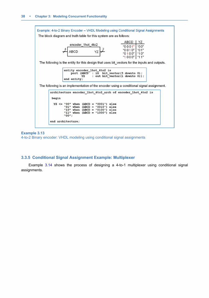
Example 3.13 shows how to model a one-hot encoder in VHDL with conditional signal assignments.Again, this approach allows the logic to be modeled directly from its functional description rather thanhaving to perform any synthesis by hand.
Example 3.127-Segment display decoder: VHDL modeling using conditional signal assignments
3.3 Conditional Signal Assignments • 37
3.3.5 Conditional Signal Assignment Example: Multiplexer
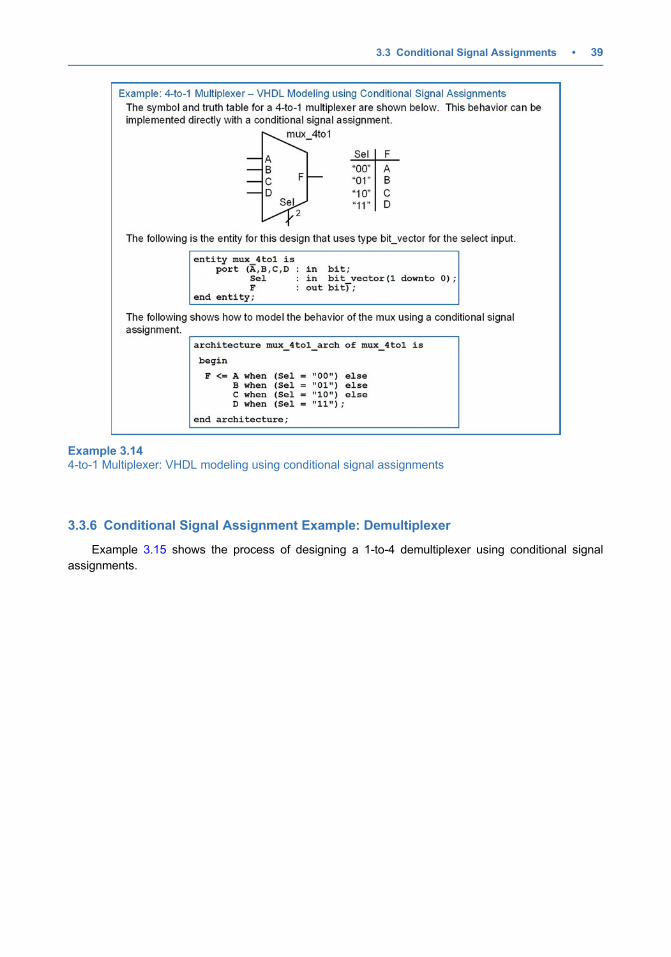
Example 3.14 shows the process of designing a 4-to-1 multiplexer using conditional signalassignments.
Example 3.134-to-2 Binary encoder: VHDL modeling using conditional signal assignments
38 • Chapter 3: Modeling Concurrent Functionality
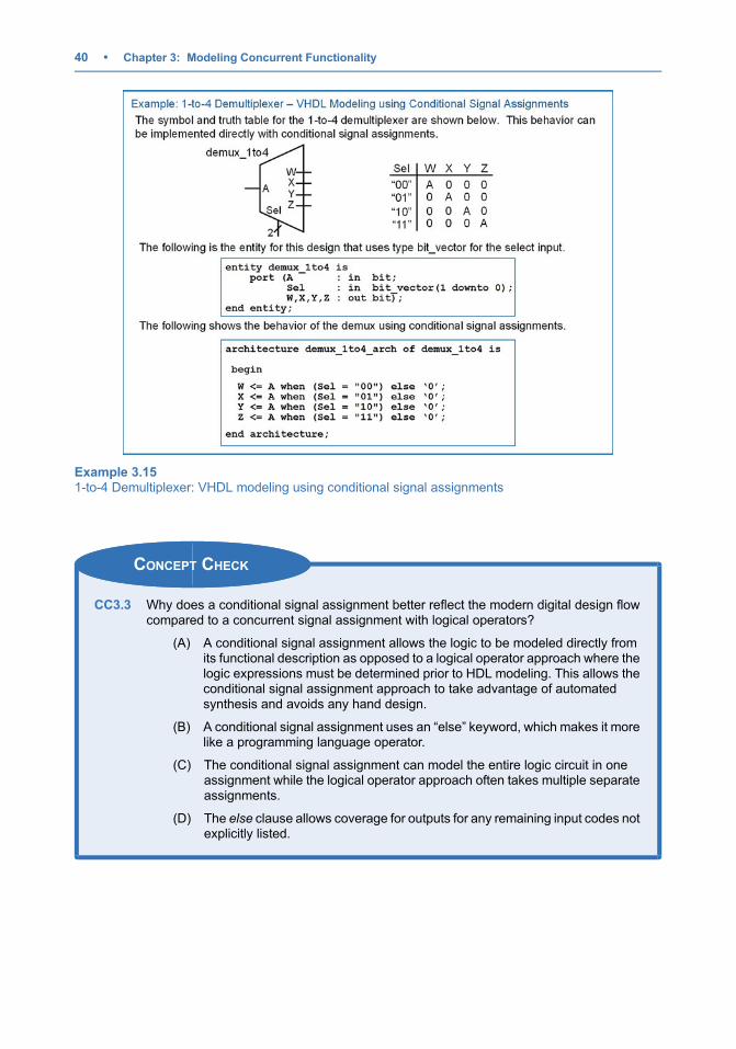
3.3.6 Conditional Signal Assignment Example: Demultiplexer
Example 3.15 shows the process of designing a 1-to-4 demultiplexer using conditional signalassignments.
Example 3.144-to-1 Multiplexer: VHDL modeling using conditional signal assignments
3.3 Conditional Signal Assignments • 39
CONCEPT CHECK
CC3.3 Why does a conditional signal assignment better reflect the modern digital design flowcompared to a concurrent signal assignment with logical operators?
(A) A conditional signal assignment allows the logic to be modeled directly fromits functional description as opposed to a logical operator approach where thelogic expressions must be determined prior to HDL modeling. This allows theconditional signal assignment approach to take advantage of automatedsynthesis and avoids any hand design.
(B) A conditional signal assignment uses an “else” keyword, which makes it morelike a programming language operator.
(C) The conditional signal assignment can model the entire logic circuit in oneassignment while the logical operator approach often takes multiple separateassignments.
(D) The else clause allows coverage for outputs for any remaining input codes notexplicitly listed.
Example 3.151-to-4 Demultiplexer: VHDL modeling using conditional signal assignments
40 • Chapter 3: Modeling Concurrent Functionality

3.4 Selected Signal Assignments
A selected signal assignment provides another technique to implement concurrent signalassignments. In this approach, the signal assignment is based on a specific value on the input signal.The keyword with is used to begin the selected signal assignment. It is then followed by the name of theinput that will be used to dictate the value of the output. Only a single variable name can be listed as theinput. This means that if the assignment is going to be based on multiple variables, they must first beconcatenated into a single vector name before starting the selected signal assignment. After the input islisted, the keyword select signifies the beginning of the signal assignments. An assignment is made to asignal based on a list of possible input values that follow the keyword when. Multiple values of the inputcodes can be used and are separated by commas. The keyword others is used to cover any input valuesthat are not explicitly stated. The syntax for a selected signal assignment is as follows:
with input_name selectsignal_name <¼ expression_1 when condition_1,
expression_2 when condition_2,:
expression_n when others;
Example:
with A selectF1 <¼ ‘1’ when ‘0’, -- F1 will be assigned ‘1’ when A¼’0’
‘0’ when ‘1’; -- F1 will be assigned ‘0’ when A¼’1’
AB <¼ A&B; -- concatenate A and B so that they can be used as a vectorwith AB selectF2 <¼ ‘0’ when “00”, -- F2 will be assigned ‘0’ when AB¼”00”
‘1’ when “01”,‘1’ when “10”,‘0’ when “11”;
with AB selectF3 <¼ ‘1’ when “01”,
‘1’ when “10”,‘0’ when others;
One feature of selected signal assignments that makes its form even more compact than othertechniques is that multiple input codes that correspond to the same output assignment can be listed onthe same line pipe (|)-delimited. The example for F3 can be equivalently described as:
with AB selectF3 <¼ ‘1’ when “01” | “10”,
‘0’ when others;
3.4.1 Selected Signal Assignment Example: SOP Circuit
Example 3.16 shows how to design a VHDL model of a combinational logic circuit using selectedsignal assignments. Note that this example uses the same truth table as in Example 3.1 to illustrate acomparison between approaches. This approach provides a model that can be created directly from thetruth table without needing to do any synthesis or minimization by hand.
3.4 Selected Signal Assignments • 41

3.4.2 Selected Signal Assignment Example: One-Hot Decoder
Example 3.17 shows how to model a 3-to-8 one-hot decoder in VHDL with selected signalassignments. Again, this approach allows the logic to be modeled directly from its functional descriptionrather than having to perform any synthesis by hand.
Example 3.16SOP Logic circuit: VHDL modeling using selected signal assignments
42 • Chapter 3: Modeling Concurrent Functionality
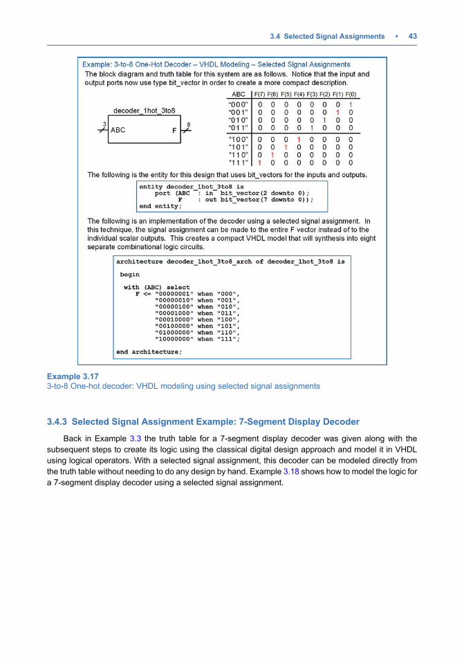
3.4.3 Selected Signal Assignment Example: 7-Segment Display Decoder
Back in Example 3.3 the truth table for a 7-segment display decoder was given along with thesubsequent steps to create its logic using the classical digital design approach and model it in VHDLusing logical operators. With a selected signal assignment, this decoder can be modeled directly fromthe truth table without needing to do any design by hand. Example 3.18 shows how to model the logic fora 7-segment display decoder using a selected signal assignment.
Example 3.173-to-8 One-hot decoder: VHDL modeling using selected signal assignments
3.4 Selected Signal Assignments • 43
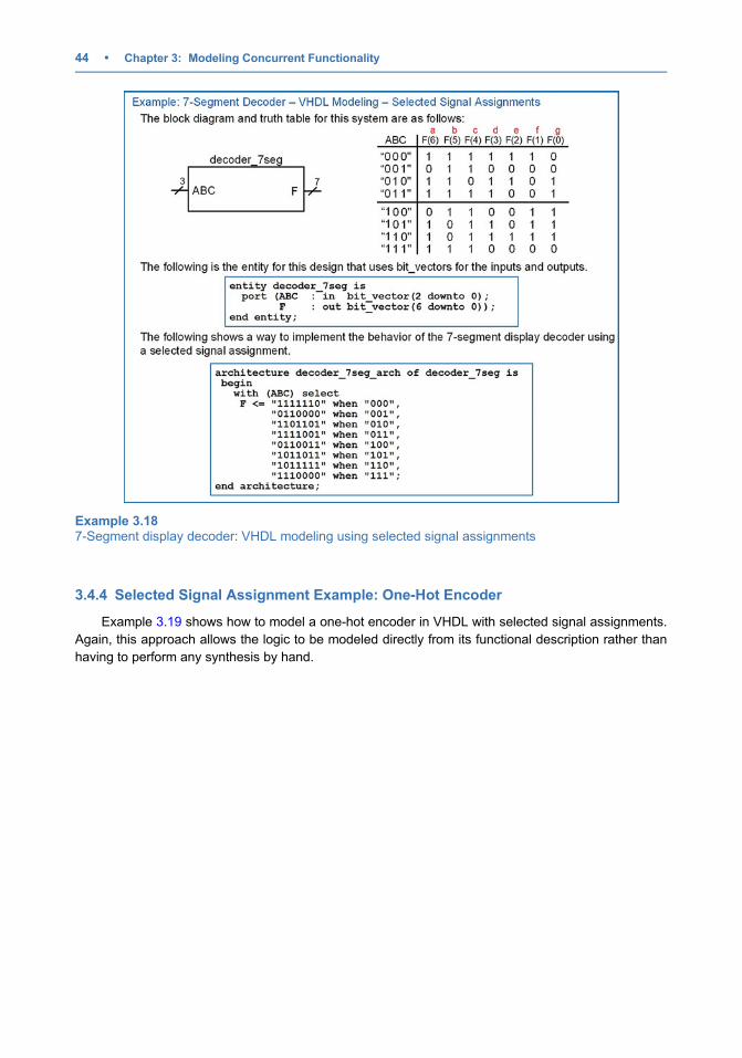
3.4.4 Selected Signal Assignment Example: One-Hot Encoder
Example 3.19 shows how to model a one-hot encoder in VHDL with selected signal assignments.Again, this approach allows the logic to be modeled directly from its functional description rather thanhaving to perform any synthesis by hand.
Example 3.187-Segment display decoder: VHDL modeling using selected signal assignments
44 • Chapter 3: Modeling Concurrent Functionality
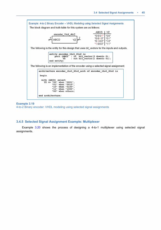
3.4.5 Selected Signal Assignment Example: Multiplexer
Example 3.20 shows the process of designing a 4-to-1 multiplexer using selected signalassignments.
Example 3.194-to-2 Binary encoder: VHDL modeling using selected signal assignments
3.4 Selected Signal Assignments • 45

3.4.6 Selected Signal Assignment Example: Demultiplexer
Example 3.21 shows the process of designing a 1-to-4 demultiplexer using selected signalassignments.
Example 3.204-to-1 Multiplexer: VHDL modeling using selected signal assignments
46 • Chapter 3: Modeling Concurrent Functionality

CONCEPT CHECK
CC3.4 Why does a selected signal assignment often require a separate concatenationoperation?
(A) Concatenating the inputs makes the assignment easier to read.
(B) A selected signal assignment only support a single signal name for its input. Ifit is desired to look at multiple signal names, they must first be concatenatedtogether to form a new signal name for use in the selected signal assignment.
(C) Since there is not an else clause, the selected signal assignment needs a wayto handle the outputs for input codes not explicitly listed.
(D) To avoid having to use multiple parentheses in the input signal list.
Example 3.211-to-4 Demultiplexer: VHDL modeling using selected signal assignments
3.4 Selected Signal Assignments • 47
3.5 Delayed Signal Assignments
3.5.1 Inertial Delay
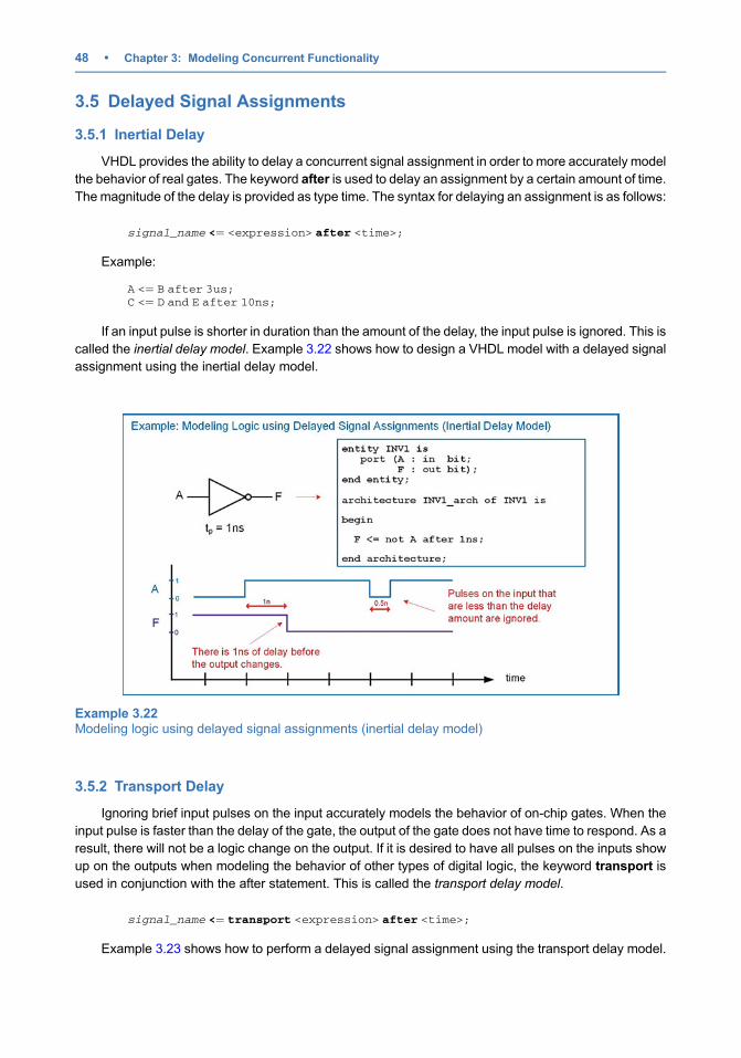
VHDL provides the ability to delay a concurrent signal assignment in order to more accurately modelthe behavior of real gates. The keyword after is used to delay an assignment by a certain amount of time.The magnitude of the delay is provided as type time. The syntax for delaying an assignment is as follows:
signal_name <¼ <expression> after <time>;
Example:
A <¼ B after 3us;C <¼ D and E after 10ns;
If an input pulse is shorter in duration than the amount of the delay, the input pulse is ignored. This iscalled the inertial delay model. Example 3.22 shows how to design a VHDL model with a delayed signalassignment using the inertial delay model.
3.5.2 Transport Delay
Ignoring brief input pulses on the input accurately models the behavior of on-chip gates. When theinput pulse is faster than the delay of the gate, the output of the gate does not have time to respond. As aresult, there will not be a logic change on the output. If it is desired to have all pulses on the inputs showup on the outputs when modeling the behavior of other types of digital logic, the keyword transport isused in conjunction with the after statement. This is called the transport delay model.
signal_name <¼ transport <expression> after <time>;
Example 3.23 shows how to perform a delayed signal assignment using the transport delay model.
Example 3.22Modeling logic using delayed signal assignments (inertial delay model)
48 • Chapter 3: Modeling Concurrent Functionality

CONCEPT CHECK
CC3.5 Can a delayed signal assignment impact multiple concurrent signal assignments?
(A) Yes. If a signal assignment with delay is made to a signal that is also used asan input in a separate concurrent signal assignment, then the delay willpropagate through both assignments.
(B) No. Only the assignment in which the delay is used will experience the delay.
Summary
v VHDL operators are defined to work on spe-cific data types. Not all operators work on alltypes within a package.
v Concurrency is the term that describesoperations being performed in parallel. Thisallows real-world system behavior to bemodeled.
v VHDL contains three direct techniques tomodel concurrent logic behavior. These areconcurrent signal assignments with logical
operators, conditional signal assignments,and selected signal assignments.
v Delay can be modeled in VHDL using eitherthe inertial or transport model. Inertial delaywill ignore pulses that are shorter than thedelay amount, while transport delay will passall transitions.
Exercise Problems
Section 3.1: VHDL Operators3.1.1 What data types do the logical operators in the
standard package work on?
3.1.2 Which logical operator has the highest prioritywhen evaluating the order of precedence ofoperations?
3.1.3 If parentheses are not used in a signal assign-ment with logical operators, how is the order ofprecedence determined?
3.1.4 What data types do the numerical operators inthe standard package work on?
3.1.5 What is the return type of a relational operator?
Example 3.23Modeling logic using delayed signal assignments (transport delay model)
Exercise Problems • 49

Section 3.2: Concurrent SignalAssignments with Logical Operators3.2.1 Design a VHDLmodel to implement the behav-
ior described by the 3-input minterm list shownin Fig. 3.1. Use concurrent signal assignmentsand logical operators. Declare your entity tomatch the block diagram provided. Use thetype bit for your ports.
Fig. 3.1System E functionality
3.2.2 Design a VHDLmodel to implement the behav-ior described by the 3-input maxterm list shownin Fig. 3.2. Use concurrent signal assignmentsand logical operators. Declare your entity tomatch the block diagram provided. Use thetype bit for your ports.
Fig. 3.2System F functionality
3.2.3 Design a VHDLmodel to implement the behav-ior described by the 3-input truth table shown inFig. 3.3. Use concurrent signal assignmentsand logical operators. Declare your entity tomatch the block diagram provided. Use thetype bit for your ports.
Fig. 3.3System G functionality
3.2.4 Design a VHDLmodel to implement the behav-ior described by the 4-input minterm list shownin Fig. 3.4. Use concurrent signal assignmentsand logical operators. Declare your entity to
match the block diagram provided. Use thetype bit for your ports.
Fig. 3.4System I functionality
3.2.5 Design a VHDLmodel to implement the behav-ior described by the 4-input maxterm list shownin Fig. 3.5. Use concurrent signal assignmentsand logical operators. Declare your entity tomatch the block diagram provided. Use thetype bit for your ports.
Fig. 3.5System J functionality
3.2.6 Design a VHDLmodel to implement the behav-ior described by the 4-input truth table shown inFig. 3.6. Use concurrent signal assignmentsand logical operators. Declare your entity tomatch the block diagram provided. Use thetype bit for your ports.
Fig. 3.6System K functionality
50 • Chapter 3: Modeling Concurrent Functionality
Section 3.3: Conditional SignalAssignments3.3.1 Design a VHDLmodel to implement the behav-
ior described by the 3-input minterm list shownin Fig. 3.1. Use conditional signal assignments.Declare your entity to match the block diagramprovided. Use the type bit for your ports.
3.3.2 Design a VHDLmodel to implement the behav-ior described by the 3-input maxterm list shownin Fig. 3.2. Use conditional signal assignments.Declare your entity to match the block diagramprovided. Use the type bit for your ports.
3.3.3 Design a VHDLmodel to implement the behav-ior described by the 3-input truth table shown inFig. 3.3. Use conditional signal assignments.Declare your entity to match the block diagramprovided. Use the type bit for your ports.
3.3.4 Design a VHDLmodel to implement the behav-ior described by the 4-input minterm list shownin Fig. 3.4. Use conditional signal assignments.Declare your entity to match the block diagramprovided. Use the type bit for your ports.
3.3.5 Design a VHDLmodel to implement the behav-ior described by the 4-input maxterm list shownin Fig. 3.5. Use conditional signal assignments.Declare your entity to match the block diagramprovided. Use the type bit for your ports.
3.3.6 Design a VHDLmodel to implement the behav-ior described by the 4-input truth table shown inFig. 3.6. Use conditional signal assignments.Declare your entity to match the block diagramprovided. Use the type bit for your ports.
Section 3.4: Selected SignalAssignments3.4.1 Design a VHDLmodel to implement the behav-
ior described by the 3-input minterm list shownin Fig. 3.1. Use selected signal assignments.Declare your entity to match the block diagramprovided. Use the type bit for your ports.
3.4.2 Design a VHDLmodel to implement the behav-ior described by the 3-input maxterm list shownin Fig. 3.2. Use selected signal assignments.Declare your entity to match the block diagramprovided. Use the type bit for your ports.
3.4.3 Design a VHDLmodel to implement the behav-ior described by the 3-input truth table shown inFig. 3.3. Use selected signal assignments.Declare your entity to match the block diagramprovided. Use the type bit for your ports.
3.4.4 Design a VHDLmodel to implement the behav-ior described by the 4-input minterm list shownin Fig. 3.4. Use selected signal assignments.Declare your entity to match the block diagramprovided. Use the type bit for your ports.
3.4.5 Design a VHDLmodel to implement the behav-ior described by the 4-input maxterm list shownin Fig. 3.5. Use selected signal assignments.Declare your entity to match the block diagramprovided. Use the type bit for your ports.
3.4.6 Design a VHDLmodel to implement the behav-ior described by the 4-input truth table shown inFig. 3.6. Use selected signal assignments.Declare your entity to match the block diagramprovided. Use the type bit for your ports.
Section 3.5: Delayed Signal Assignments3.5.1 Design a VHDLmodel to implement the behav-
ior described by the 3-input minterm list shownin Fig. 3.1. Use concurrent signal assignmentsand logical operators. Create the model so thatevery logic operation has 1 ns of inertial delay.Declare your entity to match the block diagramprovided. Use the type bit for your ports.
3.5.2 Design a VHDLmodel to implement the behav-ior described by the 3-input maxterm list shownin Fig. 3.2. Use concurrent signal assignmentsand logical operators. Create the model so thatevery logic operation has 1 ns of inertial delay.Declare your entity to match the block diagramprovided. Use the type bit for your ports.
3.5.3 Design a VHDLmodel to implement the behav-ior described by the 3-input truth table shown inFig. 3.3. Use concurrent signal assignmentsand logical operators. Create the model sothat every logic operation has 1 ns of inertialdelay. Declare your entity to match the blockdiagram provided. Use the type bit for yourports.
3.5.4 Design a VHDLmodel to implement the behav-ior described by the 4-input minterm list shownin Fig. 3.4. Use concurrent signal assignmentsand logical operators. Create the model so thatevery logic operation has 1 ns of transportdelay. Declare your entity to match the blockdiagram provided. Use the type bit for yourports.
3.5.5 Design a VHDLmodel to implement the behav-ior described by the 4-input maxterm list shownin Fig. 3.5. Use concurrent signal assignmentsand logical operators. Create the model so thatevery logic operation has 1 ns of transportdelay. Declare your entity to match the blockdiagram provided. Use the type bit for yourports.
3.5.6 Design a VHDL model to implement the behav-ior described by the 4-input truth table shown inFig. 3.6. Use concurrent signal assignments andlogical operators.Create themodel so that everylogic operation has 1 ns of transport delay.Declare your entity to match the block diagramprovided. Use the type bit for your ports.
Exercise Problems • 51