chapter 5 transmultiplexer design of t heshodhganga.inflibnet.ac.in/bitstream/10603/9393/5/14....
TRANSCRIPT
[83]
CHAPTER 5
DESIGN OF TRANSMULTIPLEXER
HE transmultiplexer system is well suited for simultaneous transmission of many data
signals through a common channel. Recently, several popular communication applications
are described in terms of the multirate transmultiplexer systems, like code-division multiple access
(CDMA), frequency-division multiple access (FDMA) and time-division multiple access (TDMA). In
particular, FDMA-types, such as orthogonal frequency division multiplexing (OFDM) and discrete multi-
tone (DMT) modulation-based systems have been more widely used than others. This implies that the
combining and separating filters are frequency selective and brick-wall shaped in their ideal cases.
Therefore, the communication channel is divided into disjointed frequency sub-channels. In contrast to
FDMA, a TDMA-type communication is allowed to the user to avail the full frequency channel during
the given time slot only [3].
5.1. GENERAL
In traditional communication networks, two standard techniques of digital multiplexing are exist:
FDM for long distance interconnections and TDM for shorter transmission. Traditionally, in conversion
process from FDM to TDM and vice versa, signal is first converted in base-band format and then
switched to other technique. This indirect conversion process is slow and lengthy. In recent years, a
considerable attention has been made to the direct conversion (i.e. without recovering the base-band
analog signal) at the multiplex level in order to decrease the system cost and increase the processing rate.
The device used for inter-connecting the two multiplex systems is known as transmultiplexer (TMUX).
Conceptually, it can be implemented by using non-DFT and DFT based approaches [8, 51, 79 and 100].
Due to limitation of analog filters, the performance of non-DFT TMUX has suffered by the
crosstalk in between adjacent channels. With the advancement in multirate digital signal processing the
non-DFT transmultiplexer has been replaced by DFT based TMUX, which is DFT implemented by using
FFT. A novel approach to TMUX system was proposed by Vetterli in 1986. In this approach, cross talk is
permitted in TDM-FDM converter stage and then cancelled in FDM- TDM converter stage. In TDM,
many signals are passed through M-fold expanders and added through delay chain. The output was
interleaved version of these signals. These signals can be recovered using time domain de-multiplexer. In
FDM, each individual signal is first passed through an expander to obtain M-fold compression of the
signal transform.
T

[84]
The interpolation filters retains one out of the three images which appear in input signal
transform. The filter responses are shifted with respect to each other so that the retained images do not
overlap and by adding all the filter output the FDM signal is generated [51,105 and 111].
The crosstalk occurred in TDM-FDM stage can be completely eliminated by careful choice of
relation between analysis and synthesis filters. In conventional approach of elimination of crosstalk in
TDM-FDM stage, the different band limited signals are separated by guard band which is not good
utilization of full channel bandwidth. The observation made by Vetterli [82] is that even if there are no
guard bands, crosstalk can be subsequently eliminated in a manner analogous to alias cancellation in
QMF banks. This idea makes judicious use of the relation between the mathematics of QMF banks and
TMUX.
Digital filter banks are used in a number of communication applications such as sub-band coders
for speech signals, frequency domain speech scramblers and image coding. These filter banks find wide
applications in many signal processing areas, such as, TMUXs [89], equalization of wireless
communication channel [3], sub-band coding of speech and image signals [2-6] and sub-band acoustic
echo cancellation [7-10].
TMUX systems are traditionally used for inter conversion between TDM and the FDM format
and have been successfully utilized in several popular communication applications, such as, CDMA,
DMT or OFDM [2]. This study focuses on a uniform-band structure in which all the incoming data
signals are interpolated at the sampling rate M followed by splitting of the received signal and up sampled
by the same integer factor (M). CMFBs will be used in designing the NPR TMUX systems [129].
Figure-5.1.1: M-Channel Maximally Decimated Transmultiplexer
M
M
M
H0 (z)
H1 (z)
HM-1 (z)
.
.
.
C (z)
F0 (z)
F1(z)
FM-1 (z)
M
M
M
.
.
.
x0 (n)
x1 (n)
xM-1 (n)
X1 (n)
XM-1(n)
y (n)
x0 (n)
[85]
The M-channel maximally decimated TMUX has been shown in Figure-5.1.1. Basically, it is a
TDM-FDM-TDM converter. It consists of synthesis block at transmitter end and precedes the analysis
block at receiver end. At the transmitter end, M-input signals are first interpolated by the factor of M and
synthesized into one composite signal using synthesis filter-bank Fk(z) for k = 0, 1,..., M − 1. Conversely,
at the receiver end, the composite signal is split out into M-output signals with the help of the analysis
filter bank Hk(z) and then decimated by a factor of M, which can be seen as the dual of M-channel QMF
bank. This study contains theoretical aspect of multicarrier communication and TMUX [3, 27 and 117].
In this chapter, the complete theory and design principles of CMFBs based TMUXs have also been
included.
5.2 TRANSMULTIPLEXER AND THEIR CLASSIFICATION
Transmultiplexer is a major component of multicarrier communication system [9 and 118].
Koilpillai [103 and 104] has studied the performance of TMUX as a dual of filter bank and designed
cross-talk TMUX system. The main drawback with this design is that, it provides only -13dB side lobe
attenuation. Further, many alternate techniques were developed to avoid the significant overlap of
channels in DFT based system [9, 43 and 119]. The CMFB based TMUX is the best among all existing
methods as concluded by Norbert et al. [46] and others [1, 99, 122 and 124]. Subsequently, its
application in different fields of communication such as VDSL system, HDSL system, high speed copper
wire communication and the other modem related applications were also investigated.
In last decade, Martin et al. [88-90] in their series of publications has designed CMFB based
TMUX system in NPR condition using window function of Blackman family and applied a nonlinear,
multivariable optimization technique to minimize the interference parameters like ICI and ISI. In this
study, an NPR type CMFB-TMUX design is proposed. The DFT approach was originally proposed by
Bellanger et al. [79], which was further discussed by many researchers. Due to the limitations of analog
filters, non-DFT TMUXs suffer from cross talks in between adjacent channels, but it reduces the spectral
efficiency of the channel bandwidth. With the advancement in multirate digital signaling processing,
traditional non-DFT TMUXs have been replaced by DFT based TMUXs. These transmultiplexers
employed FFT algorithm for the implementation of inverse discrete Fourier transform (IDFT) to modulate
the carriers at the transmitting end and a DFT to separate the symbols of each sub-channel at the receiving
end [1 and 127].
[86]
TMUX provides a set of orthogonal sub-carriers. These sub-carriers can be overlapped with each
other without interference due to the orthogonality [9 and 132]. This orthogonal property reduces the
cross talk between the adjacent channels and eliminates the requirement of guard band and complex
multi-tap time domain equalizers, which further reduces the computational complexity. The realization of
strictly orthogonal analog filers is impossible in case of non-DFT TMUX [9]. However, in DFT based
TMUXs, the filters have relatively large overlapping side-lobes (-13dB) which causes a deviation from
ideal multicarrier scheme of independent carriers in a dispersive channel and the significant overlap
between the signaling filers results in a performance degradation. An alternative signaling scheme was
also proposed [55 and 56] in which the synthesis and analysis part of TMUX using CMFB approach has
been designed.
This technique uses the filters of larger length than the filters used in DFT based approach and
typically results in much lower side lobes levels varying from -20 dB to -60 dB. The improved stop-band
attenuation and sub-channelization results in both lower level of ICI and greater robustness to narrow-
band interference. Moreover, CMFB can be implemented in a computationally efficient manner using
poly-phase representation of the filter bank and the design is much simpler because all the filters are
derived from a single prototype filter. On the basis of implementation technique the TMUX is classified
into following categories [9 and 46].
5.2.1 Non-DFT TMUX
This is a traditional approach of implementation in which TMUX is designed with the help of
analog based devices. Each block of the TDM-FDM modulator consists of an interpolator and a single
side-band modulator. For FDM-TDM conversion, the transmitted signal is separated out into M
consecutive signals by filtering with M-band pass filters corresponding to the TMUX sub-channels. The
signal in each sub-channel is down sampled by a factor of M and frequency translation is done by a
single-sideband modulator. This normally suffers with ISI and ICI or crosstalk problems due to low stop-
band attenuation and transition band in analog filters. The cross talk can be minimized by providing guard
band between adjacent bands, which reduces the spectral efficiency of the channel bandwidth [84].
5.2.2 DFT TMUX
With the advancement of multirate signal processing, the degraded performance of the non-DFT
TMUX can be improved by employing an IDFT to synthesize the sum of the modulated carriers at the
transmitter and a DFT to separate the carriers out of the received signal at the receiver. It is known as
DMT technique and implemented easily using the FFT algorithm. Compression and expansion at
[87]
transmitter and receiver side is implemented using interpolators and decimators. The M-input signals
[x0(n), x1(n)…………. xM-1(n)] are interpolated and pass through the synthesis filter bank
[F0(z), F1 (z)………. FM-1(z)] are the synthesis filters. The M input signals and combine to produce the
FDM signal. At the other end, the FDM signal y(n) is passed through the analysis filter bank [H0(z),
H1(z)………. HM-1(z)] and then decimated to get back the TDM signals. Recently, cosine modulation
technique has gained popularity among the research community as it is more efficient [8, 103 and 104].
5.2.3 Cosine Modulated TMUX
Cosine modulation is an effective technique for constructing the filter bank of the synthesis and
analysis sections of a TMUX. Commercially, it is known as Discrete Wavelet Multi-tone (DWMT)
technique [1, 9, 46 and 137]. In this approach, the filters of both sections are designed by cosine
modulation of a linearly phase low-pass prototype filter as compared to the case where all the sub-filters
are designed and implemented separately. This implementation is significantly more efficient, faster and
gives low cost and less complications. So, by designing a good quality prototype filter, a better TMUX
can be produced which has small interference parameters.
Let, p(n) is the impulse response of the low pass filter. By using the cosine modulation, other
band-pass filters are obtained as where, f(n) and h(n) are the filters of synthesis and analysis section,
respectively [95]. The term {(-1) r. π/4} is essential in order to suppress the most significant aliasing terms
(related with the crosstalk components) generated at transmitting bank, as proved by Vetterli [82]. The
interference parameters can be further reduced by the optimization process. In some cases, CMFB
approach gives high stop band attenuation varying from -23 dB to -58 dB as compared to DFT based
TMUX. Similarly, the interference level is about to 20 dB better than their counterpart [13 and 84].
5.3 PERFORMANCE PARAMETERS OF TMUXS
The z-transform of the output signal at the lth channel in terms of the z-transform of the input
signal is given by below, where, 푋 (푧) denotes the input signals for k = 0, 1, 2, 3 … (M-1).
푋 (푧) =1푀
퐻 푧 푊 퐶 푧 푊 퐹 푧 푊 푋 (푧),
(5.3.1)
where, Wm = e -j2πm/M and C (z) represents the transmission characteristics of the transmission channel.
[88]
X (z) = X (z)1M
H z W C z W F z W
+ X (z)1M
H z W C z W F z W,
,
(5.3.2)
In the above relationship, the first term represents the output due to the symbols transmitted in the lth
channel which is the sum of desired output and inter symbol interference (ISI) which is caused by other
symbols in same sub-channel. The ISI originates due to two reasons, the non-ideal nature of the filter
within their pass-bands and the channel transmission frequency response which is not exactly constant
within each sub-channel. The second term represents the ICI, the interferences of the filters in their stop-
band [89 and 118]. The (5.3.2) can be expressed using the transfer function between channels as follows-
푋 (푧) = 푇 (푧),
(5.3.3)
where, Tlk (z) is the transfer function between the output of the lth sub-channel and the input of the
kth sub-channel, which is defined as-
푇 (푧) = 퐻 푧 푊 퐶 푧 푊 퐹 푧 푊
(5.3.4)
In case of ideal channel and for the perfect reconstruction design, total interference parameters
Tlk (z) should be zero for l ≠ k and one for l = k, i.e. the total error and interference are zero. In the real
communication world, where the transmission channel itself introduces considerable distortion, it is better
to go for NPR approach [88]. In NPR systems the constraints and complexity of perfect reconstruction is
relaxed by allowing a small amount of interferences. The NPR system is beneficial since it provides better
stop-band performance with less complexity [12].The interference parameters which are used to compare
the performance of NPR type TMUX are given below.
[89]
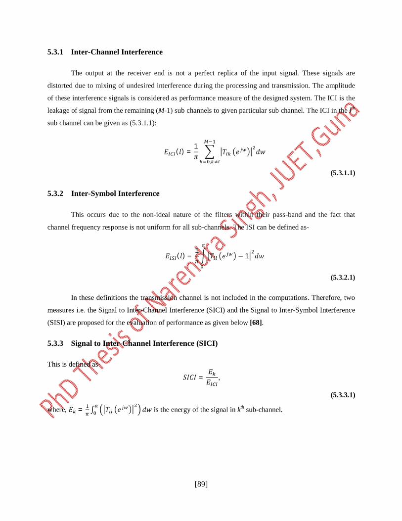
5.3.1 Inter-Channel Interference
The output at the receiver end is not a perfect replica of the input signal. These signals are
distorted due to mixing of undesired interference during the processing and transmission. The amplitude
of these interference signals is considered as performance measure of the designed system. The ICI is the
leakage of signal from the remaining (M-1) sub channels to given particular sub channel. The ICI in the lth
sub channel can be given as (5.3.1.1):
퐸 (푙) =1휋
푇 푒 푑푤,
(5.3.1.1)
5.3.2 Inter-Symbol Interference
This occurs due to the non-ideal nature of the filters within their pass-band and the fact that
channel frequency response is not uniform for all sub-channels. The ISI can be defined as-
퐸 (푙) =1휋
푇 푒 − 1 푑푤
(5.3.2.1)
In these definitions the transmission channel is not included in the computations. Therefore, two
measures i.e. the Signal to Inter-Channel Interference (SICI) and the Signal to Inter-Symbol Interference
(SISI) are proposed for the evaluation of performance as given below [68].
5.3.3 Signal to Inter-Channel Interference (SICI)
This is defined as-
푆퐼퐶퐼 =퐸퐸
,
(5.3.3.1)
where, 퐸 = ∫ 푇 푒 푑푤 is the energy of the signal in kth sub-channel.
[90]
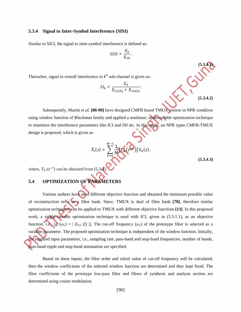
5.3.4 Signal to Inter-Symbol Interference (SISI)
Similar to SICI, the signal to inter-symbol interference is defined as-
푆퐼푆퐼 =퐸퐸
.
(5.3.4.1)
Thereafter, signal to overall interference in kth sub-channel is given as-
푆퐼 =퐸
퐸 ( ) + 퐸 ( ).
(5.3.4.2)
Subsequently, Martin et al. [88-90] have designed CMFB based TMUX system in NPR condition
using window function of Blackman family and applied a nonlinear, multivariable optimization technique
to minimize the interference parameters like ICI and ISI etc. In this study, an NPR types CMFB-TMUX
design is proposed, which is given as-
푋 (푧) =1푀
푇 푒 푋 (푧),
(5.3.4.3)
where, Tlk (e jω) can be obtained from (5.3.4).
5.4 OPTIMIZATION OF PARAMETERS
Various authors have used different objective function and obtained the minimum possible value
of reconstruction error in a filter bank. Since, TMUX is dual of filter bank [78], therefore similar
optimization techniques can be applied to TMUX with different objective functions [13]. In this proposed
work, a single-variable optimization technique is used with ICI, given in (5.3.1.1), as an objective
function, i.e., [g (ωc) = | EICI (l) |]. The cut-off frequency (ωc) of the prototype filter is selected as a
variable parameter. The proposed optimization technique is independent of the window function. Initially,
the supplied input parameters, i.e., sampling rate, pass-band and stop-band frequencies, number of bands,
pass-band ripple and stop-band attenuation are specified.
Based on these inputs, the filter order and initial value of cut-off frequency will be calculated,
then the window coefficients of the selected window function are determined and they kept fixed. The
filter coefficients of the prototype low-pass filter and filters of synthesis and analysis section are
determined using cosine modulation.
[91]
The ICI in a particular sub-channel for current value of cut-off frequency is calculated. The
absolute value of ICI is selected as an objective function. In the optimization routine cut-off frequency of
the prototype filter is continuously iterates as per the search direction and calculate the corresponding
value of these parameters. The algorithm terminates the loop as it attains the optimum value of the
objective function. In NPR system, the perfect reconstruction conditions are certainly relaxed by allowing
a small amount of error and interferences. These interferences can be minimized by applying suitable
optimization techniques [21 and 76].
5.5 DESIGN EXAMPLES OF TRANSMULTIPLEXER
In the last half decade, Martin et al. [88-90] had done excellent work in this field. They used
cosine based fixed window functions for the design of the prototype filter of TMUXs. A specific four-
variable optimization technique is used in their design, which optimizes the weight terms of the window
function. As per [90], this technique requires a good starting point for obtaining the optimum results.
However, in the proposed work a single variable generalized optimization technique is applied. Variable
combinational window functions with high SLFOR are used for the design of prototype filter. These
window functions provide more flexibility and better performance than fixed window functions. Also,
these window functions have better far-end attenuation than widely used Kaiser window function. This
property provides better suppression of ICI as compared to other window functions. It is evident from the
results of the quoted examples that the obtained values of interference parameters are much better than
earlier reported work.
In the example considered below, the prototype filter is designed with window functions of
variable and combinational family i.e. Kaiser, Modified Blackman, PC4, PC6 and proposed window,
respectively. The same input parameters such as pass-band and stop-band frequencies, filter length are
selected as in reported work of Martin et al. [88 and 90]. The optimization algorithm discussed in
previous is applied to optimize the filter coefficients of prototype filter to get the minimum value of
interference parameters. The obtained optimized value of these parameters like ICI and ISI and others are
tabulated in Table - 5.1. Since, TMUXs multiplex the multiple data coming from different sources and
therefore, it is necessary to analyze the ICI in each sub-channel.
[92]
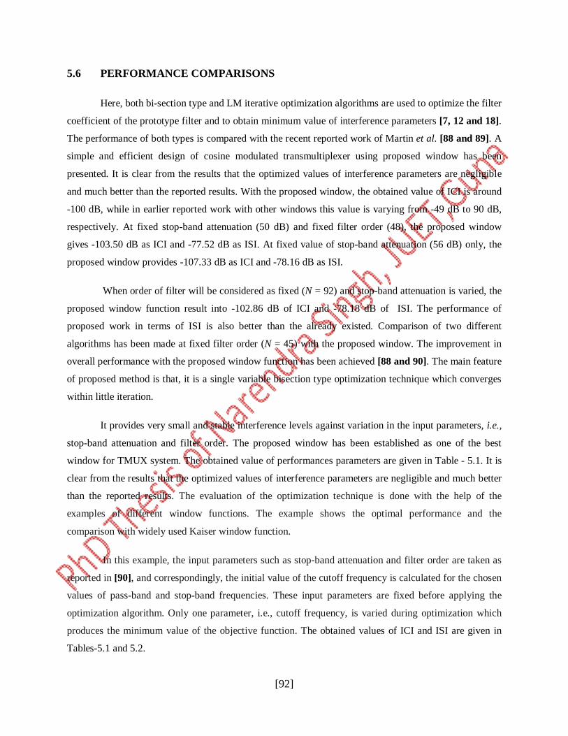
5.6 PERFORMANCE COMPARISONS
Here, both bi-section type and LM iterative optimization algorithms are used to optimize the filter
coefficient of the prototype filter and to obtain minimum value of interference parameters [7, 12 and 18].
The performance of both types is compared with the recent reported work of Martin et al. [88 and 89]. A
simple and efficient design of cosine modulated transmultiplexer using proposed window has been
presented. It is clear from the results that the optimized values of interference parameters are negligible
and much better than the reported results. With the proposed window, the obtained value of ICI is around
-100 dB, while in earlier reported work with other windows this value is varying from -49 dB to 90 dB,
respectively. At fixed stop-band attenuation (50 dB) and fixed filter order (48), the proposed window
gives -103.50 dB as ICI and -77.52 dB as ISI. At fixed value of stop-band attenuation (56 dB) only, the
proposed window provides -107.33 dB as ICI and -78.16 dB as ISI.
When order of filter will be considered as fixed (N = 92) and stop-band attenuation is varied, the
proposed window function result into -102.86 dB of ICI and -78.18 dB of ISI. The performance of
proposed work in terms of ISI is also better than the already existed. Comparison of two different
algorithms has been made at fixed filter order (N = 45) with the proposed window. The improvement in
overall performance with the proposed window function has been achieved [88 and 90]. The main feature
of proposed method is that, it is a single variable bisection type optimization technique which converges
within little iteration.
It provides very small and stable interference levels against variation in the input parameters, i.e.,
stop-band attenuation and filter order. The proposed window has been established as one of the best
window for TMUX system. The obtained value of performances parameters are given in Table - 5.1. It is
clear from the results that the optimized values of interference parameters are negligible and much better
than the reported results. The evaluation of the optimization technique is done with the help of the
examples of different window functions. The example shows the optimal performance and the
comparison with widely used Kaiser window function.
In this example, the input parameters such as stop-band attenuation and filter order are taken as
reported in [90], and correspondingly, the initial value of the cutoff frequency is calculated for the chosen
values of pass-band and stop-band frequencies. These input parameters are fixed before applying the
optimization algorithm. Only one parameter, i.e., cutoff frequency, is varied during optimization which
produces the minimum value of the objective function. The obtained values of ICI and ISI are given in
Tables-5.1 and 5.2.
[93]
Table- 5.1: The performance comparison with earlier work.
S. No. Window function ATT N ICI (dB) ISI (dB)
1 Modified Blackman 50 48 -49.81 -46.06
2 Kaiser 50 48 -108.58 -72.24
3 PC4 50 48 -99.97 -72.23
4 PC6 50 48 -100.17 -72.24
5 Proposed window 50 48 -103.50 -77.52
Table- 5.2: The performance comparison for stop band attenuation.
S. No. Window function ATT N ICI (dB) ISI (dB)
1 Kaiser 56 54 -92.59 -72.22
2 PC4 56 102 -97.99 -72.23
3 PC6 56 82 -102.05 -72.24
4 Proposed window 56 56 -107.33 -78.16
Table- 5.3: The performance comparison for filter order (N=92).
S. No. Window function ATT N ICI (dB) ISI (dB)
1 Kaiser 90 92 -98.78 -72.22
2 PC4 51 92 -102.67 -72.23
3 PC6 59 92 -98.90 -72.24
4 Proposed window 54 92 -102.86 -78.18
[94]
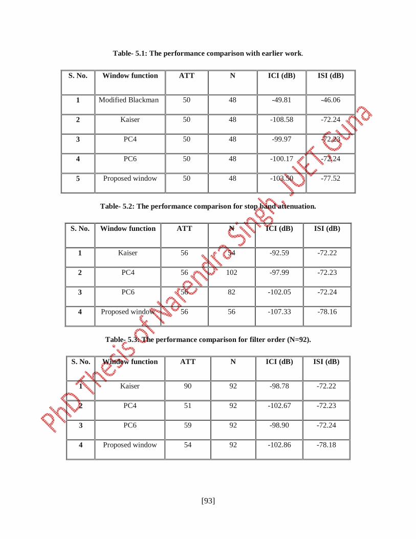
ISI and ICI of TMUX system have been calculated by using two different algorithms bi-section
algorithm and LM algorithms. The window functions in terms of ICI and ISI for the above two algorithms
are shown in Tables - 5.4 and 5.5, respectively.
Table- 5.4: The performance comparison ICI for filter order (N=45) by using two different
optimization algorithms.
S. No. Window function ATT N ICI(dB)
Bi-section
algorithm
LM
algorithm
1 Kaiser 50 45 -95.88 -73.37
2 PC4 50 45 -113.90 -73.49
3 PC6 50 45 -115.20 -74.66
4 Proposed window 50 45 -116.8 -82.84
Table- 5.5: The performance comparison ISI for filter order (N=45) by using two different
optimization algorithms.
S. No. Window function ATT N ISI(dB) ICI(dB)
Bi-section
algorithm
LM algorithm
1 Kaiser 50 45 -76.92 -76.26
2 PC4 50 45 -77.15 -77.24
3 PC6 50 45 -77.25 -75.25
4 Proposed window 50 45 -78.24 -76.28
Therefore, it can easily be depicted from the results shown in above tables that the proposed
window outperforms than all other existing techniques available in the literature.
*******************************************************