helmut scheuermann helnz gocklerblock diagram of a 60-channel transmultiplexer. (a) tdm-fdm...
TRANSCRIPT

Reprint from PROCEEDINGS of the IEEE 69 November l981 pp. 1419--1450
HELMUT SCHEUERMANN
AND HElNZ GOCKLER
PROCEEDINGS OF THE IEEE, VOL. 69, NO. 11, KWEMBER 1981
HELMUT SCHEUERMANN AND HEINZ a C K L E R
Abstract-With this survey, an attempt is made to describe the p a t majority of all known methods of digital transmultiplexing (Le., con- version) of time-division-multiplex (TDM) t o frequency-division- multiplex (FDM) signals, and vice versa. To this end, the individual transmultiplexer approaches are classified into four categories accord- ing to the undedying algorithm: Bandpass filter bank, low-pass filter bank, Weaver structure method, and multistage modulation method. Finally, the overall performance of the various transmultiplexer ap- proaches are compared with each other by means of different criteria [l], such as stability under looped conditions, absolute value of the group delay, computational and control complexity, modularity, poten- tial of intelligible crosstalk, absence of an additional analog frequency conversion, and the impact of out+£-band signaling. For a more pro- found understanding of the individual digital transmultiplexer ap- proaches, the main chapter is preceded by an introductory discussion on analog and digital generation of single-sideband signals. In this context, the associated problems of sample rate alteration and multi- rate filtering arising f ~ o m digital signal processing are dealt with.
Manuscript received February 8, 1980; revised July 30, 1981. This work was supported in part by the German Federal Ministry of Re- search and Technology.
The authors are with the Advanced Development Department, AEG- Telefunken Kommunikationstechnik, P.O.B. 1120, D-71 50 Backnang, Germany.
I. INTRODUCTION NALOG TRANSMISSION and switching facilities for A telephony signals are nowadays to a growing extent being expanded and replaced by digital facilities.
Thereby the conventional multiple utilization of transmission paths. by frequency-division-multiplex (FDM) is being substi- tuted by time-division-multiplex (TDM) techniques. The chief advantages of digital TDM transmission as compared with analog FDM transmission are as follows:
1) no generation of additive noise on the transmission path;
2) within certain limits, no occurrence of interference through crosstalk;
3) possibility for concentration of switching and trans- mission facilities.
The widespread use and high investment outlays of the installed facilities will require that analog and digital technolo- gies coexist well into the foreseeable future. This will lead to an increasing extent to interfaces between analog and digital sections of the toll communication network. Interconnection

PROCEEDINGS O F THE IEEE, VOL. 69, NO. 11, NOVEMBER 1981
FDM:
SG :
FDM
Frequency Division Multiplex
Supergroup
PDM : Time Divi Multiplex
Fig. 1 . Block diagram of a 60-channel transmultiplexer. (a) TDM-FDM direction. (b) FDM-TDM direction.
at these places could be made, in principle, using the available FDM and TDM terminal-station equipment. In doing so, the process goes-for instance, when converting from the analog to the digital signal representation-from the particular FDM- carrier hierarchy stage down t o the voice frequency level and proceeds from there t o the corresponding TDM hierarchy stage. Better system performance and a more economical solution may be achieved with an interfacing facility specially designed for this purpose. For such facility, the designation "trans- multiplexer" has been coined.
Signal processing in a transmultiplexer can be done either in the analog or in the digital way. As compared with analog technology, digital technology offers the advantages of being suited for integration, and of the absence of circuit adjustment and variation of equipment performance with time and tem- perature, etc.
A great number of publications on digitally implemented transmultiplexers appeared over the last years [ 1 ] -[7]. With the increasing number of transmultiplexing methods' being disclosed, it becomes ever niore difficult t o maintain an over- view and, for given conditions, t o choose a suitable approach. It is therefore the aim of this contribution to describe the fun- damental algorithms i n a tutorial manner, to point out the common features of the individual known transmultiplexer approaches and to classify these methods according t o the inherent digital signal processing procedures. To this end, the functions of individual subassemblies of a transmultiplexer are explained in the next section. For a deeper understanding of digital transmultiplexer algorithms, the possibilities of analog single-sideband modulation are recalled and, in addition, ex- tended to digital signal processing in the subsequent sections. Particularly, the questions of sample rate alteration and multi- rate filtering (interpolation, decimation) are treated in detail. In the main section, the individual known transmultiplexer ap- proaches are classified into four categories according to the underlying algorithm: Bandpass filter-bank method, low-pass fiiter-bank method, Weaver structure method, and multistage modulation methods. Finally, in the concluding sections, the
sion
various transmultiplexing methods described in this paper are compared with each other on the basis of a set of criteria essentially introduced by Fettweis [ 1 1.
In its basic function, a transmultiplexer represents a single- sideband modulator. As an example for the European format, Fig. 1 shows the functional block diagram of a 60channel transrnultiplexer for the TDM-FDM-direction (Fig. l(a)) and for the FDM-TDM-direction (Fig. l(b)): The data streams of two PCM TDM systems, each of them comprising 30 telephone channels corresponding to the lowest European TDM hier- archical level (PCM 30), are simultaneously translated to the FDM supergroup (SG) level in the frequency range from 3 1 2 kHz to 552 kHz, and vice versa [ 11, [2]. In contrast to that, in North America and Japan the lowest hierarchy of the TDM system is made up of only 24 telephone channels. Under these constraints, a transmultiplexer is generally applied t o the con- version of one 24channel PCM TDM data stream t o two (primary) groups of the FDM hierarchy, each of them compris- ing 12 channels in the frequency band ranging from 60 t o 108 kHz, and vice versa [ l ] , [2]. Moreover, in Japan some attempts have been made t o realize a 120-channel transmulti- plexer, corresponding t o an interface between five 24-channel PCM TDM formats and two FDM supergroups [ l ] , [8], [9] . Subsequently, however, the more general discussion will pre- dominantly be based on the 60channel approach. Neverthe- less, North American and Japanese 24-channel transmulti- plexers (which can usually be adapted t o another number of channels without difficulty) will be considered in the main chapter as well. On the contrary, facilities, such as those re- quired for signaling, dialing pulses conversion, and supervision will only be treated marginally, since they have no bearing on the understanding of the basic principles of operation. The interested reader is referred t o [75] , [76].
In the European approach, the two PCM TDM bit streams (PCM 30), each with a transmission speed of 2.048 Mbitls, are applied t o a receiver R (Fig. l(a)). Here, the two TDM signals

SCHEUERMANN AND GOCKLER: DIGITAL TRANSMULTIPLEXING METHODS 1421
TABLE I SOME SPECIFICATIONS FOR 60-CHAXNEL TRANSMULTIPLEXERS ACCORDING
TO C C I n RECOMMENDATION G. 792 AND G. 793
Magnitude rcsponsc *
6 W H z to 2LOOHz -0.6dB 5 a 5 0 . 6 d B
Maximum allowancc at thr band edges
300 Hz -0.6dB r a C 1.7dB
3400 Hz -0 .6dB 5 o S 2.LdB
Group delay * (absolute value) T C 3ms
Distortion
1000 Hz to 2 6 0 0 H z AT 4 0Sms
600 Hz to l 0 0 0 H z AT a 1.5n-s
504 Hz to 6 0 0 H z , 2600Hz to 2 8 W H z AT C 2 m s
Minimum crosstalk attenuation bctwccn any two channcls*
Intclligiblc crosstalk 65 dB
Unintelligible crosstalk 58dB
Maximum idle channcls noisc with all channcls loadad
cxccpt thc one measured. rrtcrcncrd to peak signal
point * - 8OdB
Maximum in - band r m s nonlinear distortion, r r tcrcncrd
t o peak signal point * -40dB
Out -of - band signalling a t 3825Hz
Ptlot frtqumcics at 3 920Hz
*Measurement of the multiplexed analog signal, the digital ports being looped.
equipment are compiled in the CCITT Recommendation G.792. In addition, some general considerations on trans- multiplexers can be taken from the CCITT Recommendation G.791, whereas the particular specifications of a 60channel transmultiplexer, such as pilots, signaling, etc., can be found in the CCITT Recommendation G.793. From these recommenda- tions, the most important requirements for a 60channel trans- multiplexer are given in Table I. It must be noted that these data are, in general, to be measured at the analog (FDM) ports, the digital (TDM) ports being looped. As a consequence, the actual constraints to be imposed on any individual filter of a transmultiplexer may be much more stringent. Furthermore, the individual filter specifications are generally different for the various transmultiplexing methods to be described in the sequel.
From the theory of analog signal processing, three basic methods are known for producing a single-sideband signal. These methods are described at length in an overview paper of Kurth [ 121, for which reason the principles will only briefly be touched upon here. All three methods use for frequency translation a type of doublesideband amplitude modulation. The differences lie in the sequential order of modulation and sideband suppression, as well as in the method of sideband suppression itself. Mathematically, the single-sideband signal may be expressed by means of analytical signals
y,(t) = x(t) cos 2rfCt - 2(t) sin 2nfct ( l a )
y,(t) = x(t) cos 2n fc t + 2 0 ) sin 2nfc t
where
are synchronized, and the particular signal levels are adjusted so as to enable a subsequent digital processing. This is fol- lowed, for each of the branches, by a serial-parallel (SIP) con- verter, which converts the interleaved TDM signals to parallel form. The samples, in Europe encoded according to the A-law [10], are converted in the expander (EX) to linearly encoded samples. Subsequently, the FDM signal is digitally generated by means of a bank of single-sideband modulators (SSB-MOD). A digital-to-analog (D/A) converter, followed by an analog filter for smoothing the resulting staircase function, produces the desired FDM signal at the supergroup level.
If we consider the operations of Fig. l (a) in reverse sequence, we obtain the FDM-TDM conversion shown in Fig. l(b). In general, the frequency- to time-division-multiplex conversion may be derived from the TDM to FDM conversion by trans- position [ 1 1 l. For this reason, we can limit ourselves in the following to the various methods of producing singlesideband signals; thus, only the subassembly SSB-MOD will be treated in detail. Suffice to say that a North American or Japanese 24-channel PCM TDM to FDM group-band translator (with a bit rate of 1.544 Mbit/s and inherent p-law companding [10]) is made up of the same building blocks as a 60channel trans- multiplexer according to Fig. 1.
The remaining questions to be considered in this section are primarily concerned with allowed signal irnpairnients-noise, crosstalk, phase, and frequency distortion, and nonlinear dis- tortion. The requirements common to all transmultiplexing
represents the Hilbert transform of the input signal x(t) and fc the carrier frequency. Equation (la) denotes the upper sideband and (lb) the lower one.
A. Hartley S Method [13]
The immediate implementation of (1) leads to the Hartley's method. The input signal is modulated onto the carrier cos 2rfct and the Hilbert transform of the input signal onto the orthogonal camer sin 21Tfct. After that, the two branch signals are subtracted from or added to each other, depending on whether the translated spectrum so produced is to be non- inverted or inverted.
Fig. 2(a) depicts the principle of implementation of this method and Fig. 2(b) the associated frequency spectra, from which the operating principle becomes clear. The unwanted sideband is cancelled by compensation.
A practical implementation of this method is shown in Fig. 3. In this case, two signals, shifted in phase through all-pass net- works by n/2 with respect to each other, are derived from the input signal.
B. Weover S Method (2 41 The baseband signal is first translated by means of an auxil-
iary carrier (Fig. 4(a)), whose frequency normally Lies in the center of the usable band (Fig. 4(b)). Figs. 4(c) and (d) depict the corresponding frequency spectra for in phase and quadrature signals upon this translation. The low-pass filters that follow (LP in Figs. 4(a), ( e ) suppress the spectral compo-

PROCEEDINGS O F THE IEEE, VOL. 69, NO. 11, NOVEMBER 1981
I cos ZTtf,t
(b) f
Fig. 2 . Singlesideband modulation according to Hartley's method.
cos 2 K f C t
l sin ZTCfCt
Fig. 3. Modified SSB-MOD according to Hartley.
nents for f > If0 I (Figs. 4( f ) , (g)). This is subsequently fol- lowed in each branch by a translation into the ultimate fre- quency band (Figs. 4(h), (i)). Through addition of the two signals X gi(t) and X 3q (t) (Fig. 4(a)), the frequency compo- nents within the useable frequency band are compensated in such a way that the desired single-sideband signal is produced (Fig. 46)).
C. Filtering Method
The oldest and in analog signal processing normally used method is the double-sideband amplitude modulation with subsequent suppression of the unwanted sideband (Fig. 5). As filter, either a low-pass or a high-pass filter may basically be used, depending on whether the noninverted or inverted signal
Fig. 4. Single-sideband modulation according t o Weaver's method.
spectrum is desired. In general, however, modulation products of nonideal modulators have to be filtered out, so that a band- pass filter must be used.
IV. DIGITAL SINGLE-SIDEBAND MODULATION The principles of singlesideband modulation outlined for
analog systems in the preceding section can also be used with digital signal processing. The frequency spectra are now periodic with the sampling frequency fAY (Fig. 6(a)).
For estimation of the total amount of digital circuitry, the following considerations concerning implementation are made.

SCHEUERMANN AND GOCKLER: DIGITAL TRANSMULTZPLEXING METHODS 1423
2 Lowpass attenuation 1 Highpass attenuation
X (11 : Premodulation 1 baseband spectrum 1
YE I f ) : Two sidcband amplitude modulation
Yu(f ) : Single sideband spectrum (noninverted position1
Y, I f ) : Single sideband spectrum {inverted position)
Fig. 5. Single-sideband modulation according t o filtering method.
is = = sampling frequency
(c) Fig. 6 . Digital singlesideband modulation.
If it is desired to form the FDM signal (Fig. 7) of, say, a 60- channel transmultiplexer, a bank of 60 singlesideband modu- lators would be required. If the signal bandwidth of a single channel is assumed to be BK = 4 kHz, the FDM signal needs a bandwidth of (cf., Fig. 7)
To be able to perform analog filtering after the D/A converter (Fig. l), an unconstrained transition band has to be provided. Approximately fSp = 16 kHz are assumed for this band, yield- ing an analog filter of tractable order. Since, according to the Sampling Theorem the sampling frequency has to be at least double the maximum signal frequency, the sampling frequency is (cf., Fig. 7)
Fig. 7. Digital FDM signal.
The amount of circuitry, particularly the number of arithmetic operations, that would arise i f such a transmultiplexer were to be implemented, is so overwhelming that any further con- sideration is superfluous [ 151.
If efforts to process the digital signals at lower sampling rates should prove to be successful, drastic savings could be achieved for the following reasons:
1) the amount of arithmetic operationsltime is smaller; 2) the degree of the necessary filters is reduced since the
relative width of the transition band is expanded.
If these considerations are pursued consequently, the mini- mum expenditure wil l be reached if each channel signal is processed just with the lowest possible sampling frequency ac- cording to the Sampling Theorem [ 161. In order to be able to produce the FDM signal, the sampling frequency must subse- quently be increased, requiring special interpolators. These interpolating networks wiU be treated in more detail in the next section.
If the sampling rate of a sequence is to be increased, addi- tional sampling values must be inserted. If the sampling rate is to be increased by an integer factor M, the new sampling inter- val becomes
where To is the reciprocal of the original sampling frequency. Each Mth sample of the new sequence is taken over from the sequence to be interpolated; M - 1 new samples are inserted inbetween. Two methods for solving the interpolation prob- lem are outlined in the following (a more detailed treatment can be found in [92]).
A. Interpolation by Low-Pass Filtering
The time-continuous signal ?(t) is assumed to have the frequency spectrum X(w) (Fig. 8(a)), which shall be band lifited according to
2 ( 0 ) = 0 , for 101 > ug.
The signal i ( t ) is sampled with the sampling frequency fSo = l/To assuming the Sampling Theorem to be met. Due to the sampling process the spectrum of i ( t ) is periodically re- peated on the frequency axis (Fig. 8(b)), yielding
Starting with the sequence { ~ ( V T ~ ) } the sequence (xH(vTo/~) ) is to be approximated by interpolation. This sequence could be obtained by sampling the time-continuous signal x(t ) with sampling frequency fSH = M/To increased by
PROCEEDINGS O F THE IEEE, VOL. 69 , NO. 11, NOVEMBER 1981
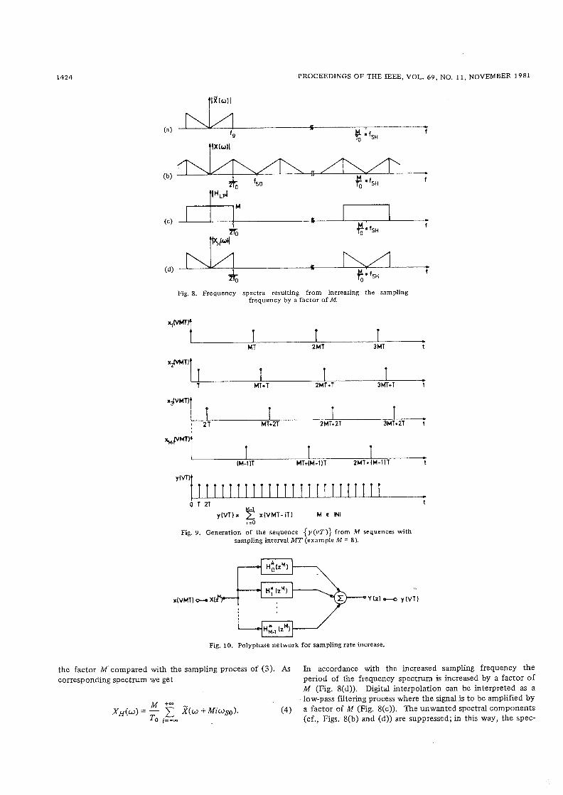
Fig. 8. Frequency spectra resulting f rom increasing the sampling frequency by a factor of M.
* 0 T 2T t
y(VT)* x (VMT- iT) M c HI 150
Fig. 9. Generation of the sequence { J J ( V T ) } from .M sequences with sampling interval MT (example M = 8).
Fig. 10. Polyphase network fo r sampling rate increase.
the factor M compared with the sampling process of (3). As In accordance with the increased sampling frequency the corresponding spectrum we get period of the frequency spectrum is increased by a factor of
M (Fig. 8(d)). Digital interpolation can be interpreted as a low-pass filtering process where the signal is to be amplified by
M +-
XH(u) = - C X(W + MiuSO). (4) a factor of M (Fig. 8(c)). The unwanted spectral components To i=-- (cf., Figs. 8(b) and (d)) are suppressed; in this way, the spec-

SCHEUERMANN AND GOCKLER: DIGITAL TRANSMULTIPLEXING METHODS
L----
-815 G -r
-l I------,
I----- @ -,j - w n 1
L.. - . . . . . .. . . ., .-.-.
L - - - - . _ 4 1
Fig. 11. Phase cancellation process in a polyphase network for inter- polation (M = 5).
trum XH(w) is approximated. An exact and detailed descrip- tion of this process can be found in [17] , [181, [92] .
B. Interpolation by Phase Compensation
For a simple explanation of the phase cancellation process M - l sequences {X~(VMT)) are derived from the sequence {X~(VMT)} with the sampling interval To = MT in such a way that the sequences result from each other by successive phase shifts corresponding to the time interval T (Fig. 9). All these subsequences are interleaved t o produce the inter-
polated output sequence ~ ( v T ) ) , sampled at the M times higher rate M/To = l /T. The corresponding network structure is shown in Fig. 10, where the summing point represents the interleaving process. As mentioned in the preceding section, the desired interpolation values to be inserted can only be produced if the polyphase network as a whole (Fig. 10) exhibits a low-pass characteristic corresponding t o Fig. 8(c), [ 191, [ 201. From Fig. 9 it is obvious that the signal sequences in the individual branches of the polyphase network (Fig. 10) can be processed at the lower input sampling rate l /MT= l . Furthermore, it will be shown that any rational (low-pass) transfer function for decimation or interpolation can be processed at the lower input sampling rate l/(MT) = tation according to Fig. 10.
If each branch filter is provided with the all-pass characteris- tic H? = eioi shown in Fig. 11, the following output spectrum is obtained (a = 27~Tf):
Range
I : . . ; r -+
(b) Fig. 12. (a) Decomposition of branch allpass networks. (b) Polyphase
structure for interpolation.
since
j ( a n p ) i = (summation orthogonality of 2 trigonometric functions) i=O
This represents ideal low-pass filtering according t o Fig. 8. The representation of Fig. 11 permits a different derivation of the low rate signal processing in the polyphase network: The phase characteristics of the branch filters can be decomposed in a linear component Gli and in a component periodic with 1/MT (Fig. 12(a)). The linear component can be realized by delays; solely the periodic component has to be realized by all-pass networks H ~ ( z ~ ) (Fig. 12(b)). Note that a reference filter in the zeroth branch of the polyphase network (Fig. 12(b)), a prerequisite for realizability, is omitted for convenience.
C. Digital Signal Interpolation in Conjunction With Filtering [l 91
Each sequence f ~ ( v ) ) whose unilateral z-transform

1426 PROCEEDINGS O F THE IEEE, VOL. 69, NO. 11, NOVEMBER 1981
exists, can be expressed by N interleaving sequences where
N-l h (0) = lim H(z) Z-+ m
(1 l b ) Y(z) = C z-" y(zN, n). (6
n =O and
In it, the expression R, = h (z - z,,)[H(z) - h(O)]. (I l c )
m Z'zmm y(zN, n) = 2 ~ ( V N + n ) z - ~
v=o (7) For the derivation of the branch filters H , ( z ~ ) from the poly-
nomial form according t o (9), a method can be found in [ l 91. represents the z-transform of the subsequences. This process is However, a general closed form solution cannot be given. For visualized by writing the terms of the sequence as follows: this reason, the form c according t o ( l l ) is used in the follow-
~ ( v T ) ) = ~ ( 0 )
Y (NI
Y(2W
Y (3N)
N sibseqgences with sampling ~ ( v N ) ) interval N T
z-transforms of subsequences y(zN>
This results in the following. The fdtering process of a se- ing. Here, one obt@ns after a tedious but straightforward quence with the sampling interval T can be reduced t o fdtering calculation of N sequences having a sampling interval of N - T (Fig. 13).
Evidently, the transfer function of the polyphase network is M R , 2;l H, (zN) = h(0) + C (Fig. 13)
(1 2) m = I P - 2 m
Starting with (g), the question arises how to get the transfer wherel
functions of the individual branch filters Hn(zN) in order t o realize a given transfer function H(z). For this purpose H(z) n E N , n E [ l , N - l ] .
l211 a) Polynomial Form
may be expressed in one of the following three equivalent The residues h(0) and R, are computed according t o ( l lb , c).
forms which can, if necessary, be transformed from each other The branch filters of the polyphase network determined by (1 2) and (1 3 ) have common characteristics [22]
uk' k=O
H(z)= where K < M
b) Pole-Zero Form
k=1 H(z) = a~ . M , where K < M
n (z - zmm) m = l
c) Residues Form (Parallel Form)
Restriction: z,, + zmk - for k # m
1) all subsystems comprise the same poles 2, ; 2) the branch filters are of the same order in z as the original
system; (9) 3) all branch filters H, have for n = 1 . - - N - 1 an N-fold
zero at z = 0.
The analytic methods mentioned above leading t o the transfer functions of the individual branch filters, are not optimal in terms of filter degree. In [23]-[25], [77] iterative methods are presented avoiding this disadvantage.
(10) VI. DESCRIPTION OF THE INDIVIDUAL TRAN~MULTIPLEXING ALGORITHMS
The principles used for FDM,'TDM conversion and vice versa are of wide interest in the whole field of digital signal process- ing. The central unit of such an assembly is formed of a band- pass filter bank with equidistantly spaced identical passbands. Furthermore, there is a need of such filter banks for speech
(1 l a ) 'Nrepresents the set of natural numbers (positive integers).

SCHEUERMANN AND GOCKLER: DIGITAL TRANSMULTIPLEXMG METHODS 1427
Fig. 13. Filtering by polyphase network.
analysis and synthesis [26]-[29], as well as for spectral an&- sis [221, [3O], [3 1 ]. Clearly, the algorithms then are adapted to the specific problems t o be solved. Note, however, that we Limit ourselves to transmultiplexing applications. To this end, in this section, the transmultiplexing algorithms are classified into four groups. These are: bandpass filter-bank, low-pass filter-bank, Weaver structure, and multistage modulation methods.
A. Bandpass Filter-Bank Method
The frequency spectrum of' the TDM input sequence {x,(uNT)} (cf., Fig. 14(b)) exhibits the following charac- teristics:
2) Frequency response has Hermitian symmetry, ie. ,
~ , ( ~ i z n T f N ) = X,*(e-i2"TfN) (1 5)
(* denotes "conjugate complex"). Starting with a TDM-sequence according t o (14) and ( IS)
the corresponding FDM signal may be gained by suitable filter- ing in a bandpass filter bank (Fig. 14(a)). Such a bank consists of N bandpass filters, whereby the passband range of the individual bandpass filters is shifted by the frequency l / (NT) with respect t o each other (Figs. 14(c), (d), (e)). The output signals of the bandpass filter bank are combined by an adder, thus forming the FDM signal. For all channels with r E [N/2, N - l ] , the resulting spectra are in the inverted position. If these signals are subjected beforehand to a double- sideband amplitude modulation with fs/2 = 1/(2T) as carrier frequency, the desired position of the frequency spectrum will be obtained. This modulation process is particularly simple, since it can be performed by multiplication with the sequence
The FDM signal then exhibits the correct frequency position for a l l channels. In the sequel, this inversion process will n o longer be mentioned explicitly.
For better understanding of this method, we set out from the model that each branch with the bandpass filter transfer function H,(z) with complex coefficients3 (Figs. 14(a), (c), (d), (e)) is replaced by an interpolating filter for generation of the high sampling rate fS = 1/T, followed by a SSB-MOD. Moreover, by means of these interpolating filters analytic baseband signals, i.e. signals with suppressed power spectrum in the frequency interval (-fS, O), have to be derived from the real-valued input sequences {x,(vNT)}. Hence, as outlined in the preceding section, the individual bandpass filters may be composed of a polyphase network with complex coefficients and a SSB-MOD (Fig. 14(h)). Thus the following formula applies:
assuming a complex-valued output sequence G~(T)). Thereby the polyphase network realizes the frequency response ~ ~ ( e i ~ ) in all branches according t o Fig. 14(a). The subse- quent single-sideband modulator causes the corresponding frequency translation along the frequency axis. From (8) f 0110 ws
According to the modulation theorem of the z-transform the ideal complex single-sideband modulation is represented by substitution of the variable
&(z) is thus obtained from H;(Z) by
According t o (16) the real single-sideband signal is obtained by
For better understanding, the complex SSB-MOD is depicted symbolically in Fig. 14(i). Using (17) and (18), there follows:
since e-jZar = 1 because of r €N.
Since the same transfer function &(z) (Fig. 14(h)) is gen- erated in each filter branch r (Fig. 14(a)), the following rela- tion holds:
Inserting equations (19) and (20) into (16), we obtain for the
2 represents the set of integer numbers. 3Complex signals and transfer functions with complex-valued coeffi-
cients are indicated by boldface letters and underlined in the figures.

PROCEEDINGS OF THE IEEE, VOL. 69, NO. 11, NOVEMBER 1981
real-valued output signe
(€9 Fig. 14. Bandpass fdter-bank method.
Interchanging the sequential order of summation and rearrang- ing yields
The term
represents the inverse discrete Fourier transform (IDFT) for
N points at the I / ( N T ) sampling rate. We thus.obtain from ( 2 1 )
N-l Y ( z ) = C z-" 2 Re L ~ n ( z N ) - IDFT { x r ( P ) )l ( 2 2 )
n=O
from which the block diagram in Fig. 15 can be derived. The filters H , ( z ~ ) with complex coefficients process complex- valued input signals. From the output signal, only the real part is needed.
The transmultiplexers described by Terrell and Rayner [ 3 2 ] , Maruta and Tomozawa [ 8 ] , [ g ] , [ 3 3 ] , [ 3 4 ] as well as by Takahata et al. 1351 work in accordance with the bandpass filter-bank method treated above.
If the number of channels is specifically fixed to

SCHEUERMANN AND GOCKLER: DIGITAL TRANSMULTIPLEXING METHODS
(i) Fig. 14. (Continued).
TDM - signal R, = real part I , = imaginary part
sampling rate 1 m Fig. 15. Block diagram of transmultiplexer according t o the bandpass
filter-bank method (see (22)).
FDM- signal
where
the described transmultiplexer method may be decomposed into subunits consisting of transmultiplexer~, each of them
processing $I input signals. The total number of subunit trans- multiplexers is then
N N N N +p"-

PROCEEDINGS OF THE IEEE, VOL. 69, NO. 11, NOVEMBER 1981
, spectral inversion 2 point lDFT
Fig. 16. Transmultiplexer for N = 2 channels according to the bandpass ffiter-bank method.
Using (23), s becomes
The simplest transmultiplexer is obtained for p = 2. From (21) results
Since in this particular case (N = 2), no imaginary parts occur in the discrete Fourier transform, we obtain the block diagram shown in Fig. 16. Hence, H , (Z~) and H~ (z2) represent filters with real coefficients.
If N is chosen such that
the entire transmultiplexer may be constructed from stages according to Fig. 16. By combining the processors of all sub- units to an overall processor, we obtain a "Hadamard pro- cessor." Within this processor only trivial multiplications with plus or minus one have t o be carried out. A transmultiplexer according to this principle has been proposed by Qaasen and Mecklenbrauker [3 6 1.
Furthermore, there exist other methods mechanizing a band- pass filter-bank in the frequency domain. They are based on fast convolution techniques applying fast Fourier transforms (FFT) [37], [38] or number theoretic transforms (NTT) [39], [40]. However, these methods seem to be less suitable due to their inherent time delay, caused by block processing of the incoming sequences. A transmultiplexing algorithm in which the bandpass filter-bank is implemented via fast convolution techniques is presented by Constantinides and Valenzuela [41]. Sophisticated simplifications were made to reduce the computational load, for instance, by taking FIR filters. To meet the specifications (60-dB minimum stopband attenuation, passband gain accuracy k0.5 dB), which do not comply with the CCITT Recommendations according to Table I, a linear phase FIR filter degree of about 1760 is needed for a 60- channel transmultiplexer. In conjunction with the minimum block length this leads t o a (looped) group delay of greater than 3 ms (cf., Table 11). Moreover, it is conjectured that even with the application of minimum phase FIR filters a group delay of less than 3 ms cannot be reached.
Most recently, a modulator-free and multiplier-free trans- multiplexer approach was proposed by Kurth e t al. [81 I , [821. It resumes the most obvious idea of directly selecting the desired frequency band, for instance of the periodic input spectrum of the TDM signal (TDM-to-FDM), at' the group or supergroup level by means of a single filter per channel-a method which has so far been abandoned due to its extremely
high computational load (cf., [ 15, ch. 41 ). The per-channel processor uses minimum-phase FIR filters which also perform interpolation (TDM-to-FDM) and decimation (FDM-to-TDM). Hardware efficiency, which can hardly be compared with that of other approaches, is obtained by implementing the FIR fil- ters in a logarithmic mode, wherein multiplication becomes addition. Lookup tables, in form of memoxy, perform conver- sion between the logarithmic and linear formats.
A similar transmultiplexer with conventional digital filters processing complex (analytic) instead of real signals was pro- posed by Del Re [83]. Before feeding the input sequences to the complex filter-bank on a per-channel basis, the analytic signals are generated by means of a phasesplitting network (Hilbert filter).
B. Low-Pass Filter-Ban k Method
If one succeeds in obtaining real signals at the output of the Fourier processor, processing of "complex" signals in the poly- . phase network can be avoided. The output signals of a Fourier processor are real if the complex input signals exhibit Hermitian symmetry. Assuming a 2Wpoint DFT processor, the following relation must hold for the complex input signals:
For a 2N-point inverse discrete Fourier transform, the follow- ing holds:
Using (26), equation (27) may be factored into
Applying the variable transformation
to the second term of (28) yields
Thus there results from (28), if in its first term r is replaced

SCHEUERMANN AND GOCKLER: DIGITAL TRANSMULTIPLEXING METHODS
TABLE I1 COMPARISON OF THE ~ N D I V I D U A L TRANSMULTIPLEXER APPROACHES 1) GROUP DELAY MEASURED AT THE ANALOG PORTS, THE DIGITAL
PORTS BEING LOOPED 2) PELLONI'S FILTER BANK (POLYPHASE NETWORK)
Rocessing of
out - of -band signalling -
hdul . scheme, 40 of c h a n ~ l s : jingle -way IS) 'WO-way IT) blt iple-way (M1
M 12 (2LI
M M)
M 12 (24
Operation rate l c h m t l
[ l / s I
Degree of
modularity
Analog frequency cowersion
Transmult~plexer
approach
Tcrrell W75 [32]
Maruta 1976 [33]
lakahata 1978 [3L,35]
: l o a m 1978 [36]
Aoyama 1980 [ 8,9 1 Constantinides 1980 [L11
Group
delay '1
?
2.3ms
> 3rns ?
?
2.3ms
-3ms
2.5ms
c 3ms?
-3ms
Not S
<3ms
25rns
7
<3ms?
7
?
>3ms
2.6ms
a3ms
IOW
l ow
low
~ d i u m
low
low
IOW
low
low
Yes
M
no ISG: yes)
Yes no
Yes
Y =S
Yes
Yes
separate ?
inherent ?
scparate ?
- inherent
separate ?
Bellanqzr l97L [L2,LL,69]
Tomlinson l976 [L81
Drogespt R78 [L61 Rdste [L71
Vary 1978 [22.30]
Pelloni 1979 1231
Narasimha 1979 [SO]
separate
separate
inherent
c i f i ca l l y applie
2,
97,30OMILIL,700L
to t ransmult ip lexing I
IOW
I ow
I O W
high
high
I ow
very low
high
medium
inherent
separate
no
no ISG: yes)
no (SG: yes1
no (SG: yes)
no (SG: yes)
Ye*
no (SG: yes1
Ye5
no
Darlington R70 [2,16]
Kurth 1971 [S21 Kao 1972 [53]
Freeny 1971 [15,51]
Singh 1973 [U]
Peled 1978 [S51
376, ODOM separate
separate
separate
- separate
Tsuda l978 [56,58]
Fethveis 1978 [59,M)]
separate ?
inherent
lation, for it leads to
2N 2N-1 N-l -
IDFT Or) = irei(2n1(2N))nr = x)cei(2~l(2N))nx xr(z ) = xi(ZzN)
~ = n W = O = Re [x:(zzN)] COS (vm) - Im [ X ~ ( Z ~ ~ ) ] sin (vn) , " . .
N N- l + j (Re [x;(zZN)] sin (m) + Im [x;(zZN)] cos (vT))
- * -j(Zn/(ZN))nH = C ;~.~,i(2~l(zN))nK. + C X,e = (- l)' Re [ X ; ( Z ~ ~ ) ] + j(- l)' Im [x:(zzN)].
H = l I f = 0
This particular Hartley type modulator is shown in Fig. 17(b). Now, 2N complex input signals have to be processed, and the low-pass prototype filter H , ( Z ~ ~ ) with real coefficients (Fig. 17(a)) is, in each case, shifted by integer multiples of the fre- quency spacing 1/(2NT). Instead of (1 8) there results
= H;(ze-i(2n/(2N))r). (29)
Hence, if one chooses the input quantities i x of an inverse discrete Fourier procesior in the sequential order correspond- ing to (28), the inverse transform is real.
Complex singlesideband sign& can be generated using the Hartley or Weaver method. In Hartley method, the real and imaginary part of the PCM signal is most efficiently derived by means of a phase network according to Fig. 3 and the re- sulting complex signal is, for convenience, modulated onto a complex camer at the frequency of 1/(4NT). Thus we obtain
Applying the same considerations as in the previous section, we obtain
where
In the above formula, x , ( z ~ ~ ) represents the complex single- sideband signal furnished by the Hartley modulator. By inter- changing the sequential order of summation, we finally obtain
The sampling rate is reduced by a factor of 2 from l/(NT) to 1/(2NT). This is possible because the frequency-translated complex single-sideband signal has spectral components only within the range [- 2 kHz, +2 kHz] . This simplifies the modu-

PROCEEDINGS O F THE IEEE, VOL. 69, NO. 11, NOVEMBER 1981
('J) Fig. 17. Generation o f an FDM signal according to the low-pass filter-
bank method.
Fig. 18 depicts the block diagram of the transmultiplexer operating according to this method.
A comparison of Fig. 15 with Fig. 18 shows that there are N complex bandpass filters required in the bandpass filter-bank method and 2N low-pass filters in the low-pass filter-bank method. The number of filters is the same, since a complex filter can be constructed from two real filters. As the sampling rate in the low-pass filter-bank method is by a factor of two lower and the absolute widths of the filter transition bands are the same, the amount of circuitry for the low-pass filters is smaller than that for the bandpass filters. On the other hand, the number of arithmetic operations in the Fourier processor remains about the same, because a 2N-point IDFT at half the sampling rate requires about the same amount of circuitry as an N-point IDFT at double sampling frequency.
A considerable part of the circuitry to be expended on the low-pass filter-bank method is required for the generation of the complex singlesideband signals. Here, the Hartley method proves to be the most favorable, for it needs about 4 poles and 4 zeros for a phase splitting network. In contrast, the Weaver method requires about 8 poles [3].
In 1974, Bellanger and Daguet [42] first proposed a trans- multiplexer according to the above mentioned low-pass filter- bank method. Further modifications of the DFT-algorithm lead to a special inverse discrete Fourier transform (102 DFT). Moreover, filters generating complex-valued signals can com- pletely be omitted. Thus a further reduction of the number of arithmetic operations is accomplished. This highly efficient type of transmultiplexer was presented by Bonnerot e t al. [43] -[45], by Drageset et al. [46], R&te et al. 1471, and by Pelloni [23].
Still another transmultiplexer, proposed by Tomlinson and method. In this approach polyphase filtering is accomplished by a single time-multiplexed filter. This filter is mechanized as a so called time-varying filter where the coefficients are periodically interchanged at a rate corresponding to the low sampling frequency. Thus the effective operation rate com- plies with the high sampling rate. At first sight, the transmulti- plexer of Tondinson and Wong [481 seems to be of lower computational complexity than the Bellanger and Daguet [42] approach. Yet the computational load of the polyphase filters, operating at the low sampling rate, is about the same as that of

SCHEUERMANN AND GOCKLER: DIGITAL TRANSMULTIPLEXING METHODS
TDM-signal FDM -signal
S S 0 : single-sideband modulator (Hartley - or Weava- method]
J , I V' W 1
sanp(ing rate 1 - 1 1 NT 2NT T
Fig. 18. Block diagram of transmultiplexer according to the low-pass filter-bank method.
the time-varying filter operating at the high sampling rate. Thereby the necessary control circuitry is not considered.
Finally in 1979, Narasimha and Peterson [50] presented a transmultiplexer using an N-point discrete cosine transform (DCT). In contrast to other low-pais filter-bank methods, with this approach no premodulation is required to generate com- plex-valued signals. This means that the individual filters of the filter bank to be derived from a low-pass prototype filter exhibit Hermitian symmetry according to (15) corresponding to real coefficients. Thus, in order to obtain the desired pass- band frequency position of the individual bandpass filters of the filter bank, the low-pass transfer function has to be shifted by
instead of
Summation of the individual channel signals yields the output signal
. [H,(~N, in[r+llZl ) + H, (p, -in [r +l12 l )l. (34)
By inspection and employing trigonometric identities we get after interchanging the sequential order of summation
. cos [d2r + 1) 5 - x,.(z~). (35) r=o n l
Here, the second term represents the DCT. Applying the substitution
as it is the case with the other low-pass filter-bank methods. f indy we obtain In conjunction with Hermitian symmetry and the Modulation Theorem of z-transform we get N-l N-l
Y(z) = C z-"G,(z~) cos = 3 [ ~ ( ~ ~ i ~ [ ~ + ~ / ~ 1 IN) + H(ze-jn lr+llZ 1 IN)]. (32) n =O r=0
Comparing this solution with (31), here only an N-point DCT ~ p p l y i n ~ the polyphase principle for interpolation we derive processor instead of a 2N-point DFT processor is needed. The with (8) branch filters of the polyphase network are modified according
to (36). With the application of linear phase FIR filters significant simplifications of hardware are possible, as it is reported in [ 501. A somewhat different implementation of the Narasimha and Peterson approach was proposed by Marshd [80]. Here the DCT is performed in an other way and the filters of the polyphase network are specifically matched single-input-double-output filters of the recursive
(33) type.

PROCEEDINGS OF THE IEEE, VOL. 69, NO. 11, NOVEMBER 1981
H, = r c u r s . ~ lwrpols H 2 = transversal l o w p a u
1 voice -band spectrum
I ,
flkHz
('J) Fig. 19. Block diagram of the transmultiplexer according to Freeny
e ta l . 1151.
C. Weaver-Structure Method
A direct method for the generation of an FDM signal is the Weaver SSB-MOD bank according t o Section 111-B. By inge- nious partitioning of filters into recursive and transversal low- pass filters, operating at different sampling rates, the amount of circuitry can be kept low. Fig. 19 shows a transmultiplexer according t o Freeny et al. [15] , [51] which operates in com- pliance with this method.
The TDM signals are being furnished at a sampling frequency of fsl = 8 kHz and modulated onto an auxiliary carrier with a frequency of fs1/4, so that the voice signal occupies the fre- quency range -2 < f/kHz < t 2. The modulation is very simple, since the sampled carrier is given by the sequence {. . - 0, 1, 0, - 1, 0 . . .). In the next step, the sampling fre- quency is doubled. The filter HI represents a recursive low- pass filter with a cutoff frequency of 2 kHz (Fig. 19(b)). At the output of filter H I , the sampling frequency is increased by a factor of M. This signal is processed by the following trans- versal low-pass filter H*. After that, the resulting spectra are shifted to the desired frequency bands by modulation. The FDM signal is obtained by summation of the individual signals.
The purpose of the two low-pass filters is twofold: They are necessary for the operation of the Weaver modulator, and they serve at the same time as interpolation filters as described in Section V-A.
Almost one year before the publication of the above Freeny papers, Kurth [52], as well, proposed a sophisticated transmul- tiplexer scheme based on the Weaver modulation. While feed-
ing the Weaver modulator by highly oversampled, ingeniously interpolated, and s p e c t r a y inverted voice-band sequences, he uses high-pass instead of low-pass filters in the Weaver modula- tor. However, the main drawback of this proposal is that, in contrast to the Freeny approach [ l 53, the Weaver modulator operates at the high sampling rate throughout. Therefore, t h e resulting operation rate is far too high for a practical imple- mentation (cf., Section IV). According t o the proposal of Kurth an exploratory TDM/FDM single-sideband generator was presented by Kao [53]. An extension of the approach reported by Freeny e t al. [ l 5 1
was-even earlier in time than [52] but not recognized in its far-reaching importance in those days-described by Darlington [ 161. To thls end, the low-pass filter cascade
In this expression, [HR ( z ) ] - l represents the recursive part and Hr(z ) the transversal part of the transfer function H(z). As outlined in Section V-C, the transfer function H(z ) can be split into parallel branches according to (8)

SCHEUERMANN AND GOCKLER: DIGITAL TRANSMULTIPLEXING METHODS
L__-- - - -J Fig. 20. T o the derivation of Darlington's transmultiplexer [ 161.
As can be seen from (13 ) , the recursive part can be put as a Furthermore, the following expressions hold: factor in front of the summation, since it is common to all additive terms. Thus using (38 ) , equation ( 3 9 ) becomes Yini(z)=. fhi (zN) N-l C Z - ' H ~ ( ~ )
N-l ( 4 4 )
r=o H(z ) = [ H ~ ( z ~ ) I - ' - C Z-'HTr(zN).
r=O ( 4 0 )
N-1 Yq i ( z ) = k q i ( z N ) C z - ~ H ~ ~ ( z ~ ) .
According to ( 4 0 ) , the transmultiplexer of Fig. 19 is modified ( 4 5 )
r=o such that the structure depicted in Fig. 20 results. The modu- lators at the input are now replaced by rotating switches. Inserting ( 4 4 ) and ( 4 5 ) into ( 4 2 ) and (43 ) , respectively, we
The part of the transmultiplexer in Fig. 20 bounded by the dashed Line can be simplified further. To this end, the FDM N - l
signal is expressed in terms of symbols used in Fig. 20 Yj&) = i h i ( z N ) C {z' 3 [e+i(2nlwir r=o
N - l According to the Modulation Theorem of z-transform, we ob- y q i ( z ) = i q i ( p ) {z-r -L [ e + f ( 2 n ~ ~ ) i r tain for Yini and Y q i r=o 2i
cos X = + (eix -t e- ix)

PROCEEDINGS OF THE IEEE, VOL. 69 , NO. 1 1 , NOVEMBER 1981
and
1 sampling f rcqucncy 8 kHz 1 8 N kHz
Fig. 21. Transmultiplexer according to Darlington [ 161.
and by inserting ( 4 6 ) and ( 4 7 ) into (411, there results
Y ( Z ) = k*i . z - ~ cos (: i$ HTr(zN) N-l i=o { r q
An interchange of summation and rearrangement of factors leads to
From ( 4 4 ) the transmultiplexer according to Darlington [ l 61 with a cosine and a sine processor can be derived, the block diagram of which is shown in Fig. 21.
Note: If the sampling rate is reduced by a factor of two at the output ports of Ihe recursive filters HR(zN), and, in addi- tion, the cosine-sine processor is provided with the conjugate complex input signals, a W-point DFT results as can easily be shown. The transmultiplexer of Fig. 21 then merges into that of Fig. 18.
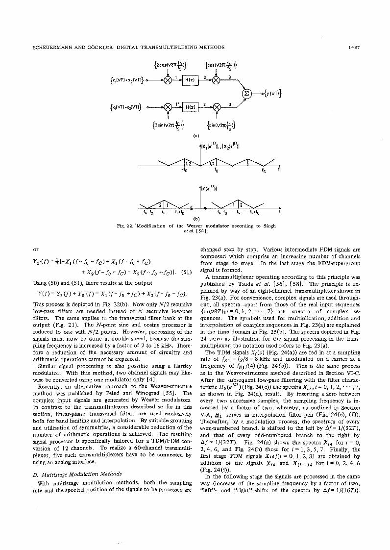
A modified version of the transmultiplexer of Fig. 21 was proposed by Singh e t al. [ 5 4 ] . By suitably processing the branch signals of the Weaver modulator, they achieve the con- version of two TDM signals using only one modulator (Fig. 22(a)). The sum of the two signals to be processed is applied to the upper branch, whereas the difference of these signals is fed into the lower branch.
According to the Modulation Theorem, the z-transform of
the summed signal at point 1 is
where fo = fs/4. The spectrum at this point is given by
+ X z ( f - f o ) + X z ( f +fob
In the subsequent low-pass filtering, frequencies higher than l fo l are suppressed, so that the signal at point 2 becomes
At point 3, we obtain
Y d f ) = 4 [ ~ 1 ( f - f o - f c ) + X 1 ( f - f o + f c )
+ X z ( f - f o - f c ) + X z ( f - f o +fc)l. (50) Using similar calculations, the signal at point 3' of the quadra- ture branch is obtained
Y3r(z) = - 3xl (ze -jzrrfalfs - i ~ n f c l f s )
+ $xl (ze -iznfO Ifs . e +izn fc l f s )
+ ~ . ~ ~ ( ~ ~ - i 2 n f ~ Ifs .e - i zn fc / f s )
- (,,-iZnfo Ifs +iZnfclfs 2 2 ' e 1
(b) Fig. 22. 'Modification of the Weaver modulato: according to Singh
e t al. [54].
Using (50) and (51), there results at the output
This process is depicted in Fig. 22(b). Now only N/2 recursive low-pass filters are needed instead of N recursive low-pass filters. The same applies to the transversal filter bank at the output (Fig. 21). The N-point sine and cosine processor is reduced to one with N/2 points. However, processing of the signals must now be done at double speed, because the sam- pling frequency is increased by a factor of 2 to 16 kHz. There- fore a reduction of the necessary amount of circuitry and arithmetic operations cannot be expected.
Similar signal processing is also possible using a HartIey modulator. With this method, two channel signals may like- wise be converted using one modulator only [4].
Recently, an alternative approach to the Weaverstructure method was published by Peled and Winograd [55]. The complex input signals are generated by Weaver modulators. In contrast to the transmultiplexers described so far in this section, linear-phase transversal filters are used exclusively both for band limiting and interpolation. By suitable grouping and utilization of symmetries, a considerable reduction of the number of arithmetic operations is achieved. The resulting signal processor is specifically tailored for a TDM/FDM con- version of 12 channels. To realize a 60-channel transmulti- plexer, five such transmultiplexers have to be connected by using an analog interface.
D. Multistage Modulation Methods
With muitistage modulation methods, both the sampling rate and the spectral position of the signals to be processed are
changed step by step. Various intermediate FDM signals are composed which comprise an increasing number of channels from stage to stage. In the last stage the FDMsupergroup signal is formed.
A transmultiplexer operating according to this principle was published by Tsuda e t al. 1561, [58]. The principle is ex- plained by way of an eight-channel transmultiplexer shown in Fig. 23(a). For convenience, complex signals are used through- out; all spectra-apart from those of the real input sequences {xi(v8T) l i = 0, 1, 2, - . . , 7)-are spectra of complex se- quences. The symbols used for multiplication, addition and interpolation of complex sequences in Fig. 23(a) are explained in the time domain in Fig. 23(b). The spectra depicted in Fig. 24 serve as illustration for the signal processing in the trms- multiplexer; the notation used refers to Fig. 23(a).
The TDM signals Xi(z) (Fig. 24(a)) are fed in at a sampling rate of fsl = fs/8 =-8 kHz and modulated on a carrier at a frequency of fsj /(4) (Fig. 24(b)). This is the same process as in the Weaver-structure method described in Section VI-C. After the subsequent low-pass filtering with the filter charac- teristic Ho(eln) (Fig. 24(c)) the spectra Xi2, i = 0, 1, 2, . - - ,7, as shown in Fig. 24(d), result. By inserting a zero between every two successive samples, the sampling frequency is in- creased by a factor of two, whereby, as outlined Section V-A, Ell serves as interpolation filter pair (Fig. 24(e), (f)). Thereafter, by a modulation process, the spectrum of every even-numbered branch is shifted to the left by Af = 1/(32T), and that of every odd-numbered branch to the right by Af = 1/(32T). Fig. 24(g) shows the spectra Xi4 for i = 0, 2,4, 6, and Fig. 24(h) those for i = l , 3, 5, 7. Finally, the first stage FDM signals Xis/(i = 0, 1, 2, 3) are obtained by addition of the signals Xi4 and X(i+1)4 for i = 0, 2, 4, 6 (Fig. 24(i)).
In the following stage the signals are processed in the same way (increase of the sampling frequency by a factor of two, "left7'- and "right"-shifts of the spectra by Af = 1/(16T)).

PROCEEDINGS O F THE IEEE, VOL. 69, NO. 11, NOVEMBER 1981
traquancy danain time domain
{ R C ~ ~ I V I I } RcIc 1~11)
B ( z l { R c C a ~ t } &
U U
(b) Fig. 23. Eight-channel transmultiplexer according to Tsuda et al. [ 5 6 ] .

SCHEUERMANN AND GoCKLER: DIGITAL TRANSMULTIPLEXING METHODS
Fig. 24. Spectra of transmultiplexer according to Fig. 23.
The corresponding spectra are sketched in Figs. 246), (k), (l), (m), (n). In the last stage the samphg frequency is increased once more by a factor of two, however, the modulation process is chosen such that the spectrum of the branch i = 0 is shifted along the frequency axis .by A f = 1/(8T), and the spectrum of the branch i = 1 by Af = 3/(8T) to the right (Figs. 24(0), (p), (q), (I), (S)). The complex FDM signal Y is pro- duced by addition of Xolo and Xllo (Fig. 24(t)). Its real part represents the desired FDM signal Y (Fig. 24(u)).
A great advantage of this method is that it only requires a small number of different filter types. go represents a pair of identical low-pass filters with a narrow transition band (Fig. 24(c)). Because these filters operate at the lowest pos- sible sampling rate, the amount of circuitry, however, remains relatively low. Furthermore, it can be shown for i > 0 (i Em that all filters _Hi exhibit the same relative width of the transi- tion band. Thus for every &(i > 0) just one filter type can be used; the frequency response is selected merely by changing

PROCEEDINGS O F THE IEEE, VOL. 69, NO. 11, NOVEMBER 1981
R = ZR -f- fs = output sampling rate fs
Fig. 24. (Continued).
Fig. 25. Transrnultiplexer subunit for 12 charineis according to Fettweis [ 5 9 ] .
the sampling frequency. In addition, the expenditure for the interpolation filters is reduced to a great extent, since nonre- cursive "half-band" filters [57! are used. In [58] an efficient experimental realization of such a 60-channel transmultiplexer isdescribed in detail, and experimental results are given.
Recently, a further transmultiplexer design based on the multistage principle of Tsuda e t al. was published by Con- stantinides and Valenzuela [73]. Here, for any two inter- mediate FDM-signals complex modulation, interpolation and filtering are performed by using only one type of a two branch
polyphase network, each combined with four operations for spectral inversion, and a band multiplexer using an FIR filter. h alternative transmultiplexer approach, based likewise on
the multistage modulation principle, is proposed by Fettweis [59]. By appropriate selection of the basic sampling rate and by ingenious arrangement of the various carrier frequencies, i t is accomplished that every modulation process is reduced t o a multiplication with a sequence of carrier samples only com- prising the trivial values of 0 or + 1.
As a consequence, the modulation processes cannot produce

Fig. 26. Spectral illustration of the transmultiplexer subunit according to Fig. 25.
quantization errors. The principles of such "multiplier-free" modulation systems are described in detail in 1601. "Mdtiplier- free" modulation schemes for TDM/FDM conversion are out- lined in [ 5 9 ] . This modulation scheme is particularly favor- able for the conversion of two 2048 Mbit/s PCM TDM bit streams (PCM30) to a supergroup of the FDM hierarchy (60 channels in the frequency band from 312 kHz to 552 kHz), since with this approach an additional analog frequency translation of the FDM signal can be avoided. The principle of the Fettweis approach will therefore be treated for a 60- channel transmdtiplexer.
The 60 TDM voice signals are converted to the FDM format using five submits, each of them for 12 voice channels (Fig. 25). Subsequently, these five intermediate FDM signals are combined to a 60-channel FDM supergroup signal (Fig. 27).
The spectra in Figs. 26 and 28 serve as illustration; the nota- tion of Fig. 25 is related to Fig. 26 and the notation of Fig. 27 corresponds to Fig. 28.
The TDM input signals Xb(z) are supplied at a sampling frequency of fso = fs/72 = 8 kHz (Fig. 26(ad). BY insert- ing two zero-valued samples between every pair of adjacent samples of the original sequence and subsequent filtering with the frequency response H. (Fig. 26(a2)), the sampling fre- quency is increased by a factor of three to fS1 = fS/24 = 24 kHz. For details on the selection of fs, = 24 kHz, the reader is referred to the discussion in 1601. By multiplication of the signals of every second channel by
the sequence ((-l)'), the spectrally inverted signals xAK are produced for n = l , 3, 5, . - - , 11 (Fig. 26(a4)); another in- crease of the sampling frequency by a factor of two to

PROCEEDINGS OF THE IEEE, VOL. 69 , NO. 11, NOVEMBER 1981
Fig. 26. (Continued).
fsz = fS/12 = 4 8 kHz follows (Fig. 26(a5)), Fig. 26(a6) fox n = 0, 2,4, . . . , 10 and Fig. 26(a7) for n = 1, 3 ,5 , . - - , l l). Furthermore, in the Figs. 26 (a,) and 26 (a7), the carrier fre- quency fC1 = fs& is shown. After the modulation process, performed by multiplication with the sequence {ol(v. 1 2 ~ ) ) = {. . - 1, 0, 1, - 1, 0, . - m), the spectra X: are obtained (Fig. 26(a8) for n = 0, 2, 4, . - - , 10 and Fig. 26(a9) for n = 1, 3, 5, . . . , 11). By low-pass filtering (Fig. 26(alo) the upper sideband is suppressed (Fig. 26(all) for n = 0, 2, 4, . . . , 10 and Fig. 26(a13) for n = 1, 3, 5, - . - , 11). After the spectral inversion of the signals in the channels n = 0, 2,4, . . . , 10, the signals xK and are added, yielding the signals X; for n = 0, 1 ,2 , . - . , 5 (Fig. 26(al4).
Subsequently the signals X: for n = 1, 2, 3 , 4 are processed in the same way as the signals X;, with the only difference that the sampling rate is twice as high at any point (Fig. 26(b 1) through (bll). The spectra for X: and X; are depicted in Fig. 26(b12). The same holds for the signal (Fig. 26(cl) through (cl2) in the next hierarchy stage.
As shown in Figs. 26(dl) through (dl;), the spectra X; and X: are processed differently; the filter characteristic H g ap- pears only in the channels 0, 1, and 10, 11. Finally, the Figs.
26(e1) through (e4) show, how the signal Yi is generated from the signals xk3, x i 3 , and X:$.
The subsequent processing of the subunit signals Yi(i= 0, 1 ,2 ,3 ,4 ) is shown in Figs. 27 and 28. After having in- creased the sampling rate by a factor of three, the signal Y: already occupies the desired frequency band (Fig. 28(al)-(~3)). The same holds for the signal Y: (Fig. 28(dl)-(d3)) if it is spectrally inverted beforehand.
In processing the signal Y4 two spectral inversions have to be performed (Fig. 28 (bl) through (ba)), one before and one after the sampling rate increase. Each of the signals Y1 and Y3 is subjected to a modulation (multiplication by the sequence (P(v - T)) = 1. - . , - 1, 0, 1, 0, - 1, 0, . . .)) and subsequently passed through a high-pass filter for sideband suppression (Fig. 28(cl) through ( ~ 4 ) and Fig. 28(el) through ( e ~ ) . Finally, the 60channel FDM supergroup signal Y(z) is formed by adding the five signals Y;, Y:, Y:, Y& and ~ 4 1 ~ (Fig. 28(f)).
The transmultiplexer approach by Fettweis is well suited for the application of wave digital filters [61], [78]. A detailed discussion on this subject can be found in [591. At present, this approach is the only transmultiplexer which might pos- sibly be mechanized by means of sampled-data filters (e.g.,

SCHEUERMANN AND GOCKLER: DIGITAL TRANSMULTPLEXING METHODS
n b n , AAM, nnnn, AAAA o 16 32 LB 6 i 80 96 112 128 IU 160 176 192 f
nnnn ILL 160 176 192 f
- 192 f
T T
AA AA, - 160 176 1 9 2 f
T T I I
I nnnr \ , a
0 16 32 6L % 128 1M3 176 l92 f
A A r \nnn,~~nn, nnnn - 0 32 L8 80 96 112 1U 160 192 f
nn M, n m n n ~ , AAAA, - 0 32 L8 80 96 112 1 U 160 192 f
- 9
0 96 192 f
AAAA nnnn, 0 32 L& 96 l k 160 192 f
nnnh AAAA, - 0 L8 6L 96 128 ILL 192 f
nnnn, AAAA, - 32 L 8 96 1 U 160 192 f
nnnnnnnn, AAMAAAA, 0 32 6L 96 128 160 192 f
Fig. 26 . (Continued).
switched-capacitor filters 1601, [62]-1641, 1791, because it does not make use of cancellation.
In the previous four sections of this chapter we have dis- cussed transmultiplexer methods which are based on one of two fundamental concepts of filter decomposition: 1) parallel decomposition using a signal processor and 2) serial decom- position resulting in a tree-like structure. Naturally, it is possible to compound both principles. Recently such an approach was disclosed by Molo [74]. This approach starts from a 2-kHz frequency shifted version of the incoming TDM-signal x r ( z N ) as it is shown in Fig. 17(a). Now the remaining transmultiplexer has t o perform a filter bank which is derived from a low-pass prototype. The basic idea is now to decompose the filter both in a parallel and in a serial manner. The manipulation of the parallel part of the filter decomposi- tion equals the low-pass principle. The treatment of the serial part resembles the derivation of a radix-2 butterfly in an FFT. Thus we get a complex 8-point IDFT followed by a tree-like structure with multipliers and modulators to perform fre- quency pre- and post-shifting. Note that the number of TDM channels t o be frequency multiplexed in this approach has to be a power of two.
VII. COMPARING THE TRANSMULTIPLEXER METHODS
If we want to compare the individual transmultiplexer methods described so far with each other, we need an ap- propriate tool for comparison. Certainly, the most important features of such a tool are cost and performance. To allow a more detailed judgment, however, a representative list of criteria will be set up as a basis for the subsequent comparison.
A. List of Criteria [I]
When comparing digital transmultiplexing methods with emphasis laid on the inherent algorithms, the subsequent list of criteria must, to some extent, be incomplete, since not all aspects of hardware are covered in this paper. Note that the sequential order of the following criteria is chosen essentially according to their relative importance in these authors' opinion.
1) 'Stability Under Looped Conditions (6.51: With the ap- plication of digital transmultiplexers, stability problems may potentially arise, since these assemblies are installed in the four-wire branch of an essentially two-wire transmission line (Fig. 29). Due to the four-wireltwo-wire transitions (hybrids),

PROCEEDINGS O F THE IEEE, VOL. 69, NO. 11, NOVEMBER 1981
* 0 96 192 f
x;k'*)l I I I I
nn, I AA, , ,m I AA, I
0 b 16 L
32 6L 80 88 96 10L l i 2 128 160 176 18L 192 f
k 6 , l P ) l I
A A, I
I
\h, , ,AA, I I
I I , I - 0 8 16 32 6L 80 88 96 1OL 112 128 160 176 18L 192 f
1x;i AA, AA AA, M,
0 16 2L L0 L8 56 72 80 96 112 120 136 1 U 152 168 176 192 f
P ,m n n M , AA, M, A A , ~ n, nn -m 0 16 2L L0 LB 56 72 80 96 112 120 136 1U 152 l68 ' l j 6 192 f
lH2 l
L
0 96 192 f IIX:I 4 \,h, AA, \,h, .m1
0 l6 2L . L8 72 80 96 112 120 ILL ljg 176 192
Fig. 26. (Continued).
transmultiplexers actually operate in a looped arrangement. osciUations will generally disturb not only the telephone Stability, however, must be guaranteed under any adverse channel under consideration but also a multiplicity, if not all, condition, such as strongly unbalanced hybrids which may adjacent channels. occur in practice. This is particularly crucial, since parasitic One way to avoid these parasitic oscillations under any

SCHEUERMANN A N D GOCKLER: D I G I T A L T R A N S M U L T I P L E X I N G METHODS
Fig. 27. Complete 60-channel transmultiplexer according to Fettweis [591.
practical circumstances is to use transversal (FIR) filters. Al- ternatively, wave digital filters (WDF) may be used when the exclusive utilization of FIR filters is inefficient. For these filter classes, potential stability under looped conditions has been proved by Meerkotter and Fettweis [65]. They showed that only minor m'easures are required for guaranteeing absolute stability. Note that their proof is based on the im- plicit assumption of a single-way modulation scheme, meaning that each input signal to the TDM/FDM-translator arrives at the output by a separate way. Furthermore, this stability theory can be extended to two-way modulation schemes using Hartley or Weaver modulators [ l 21-[ 141 for processing complex-valued signals. However, in order to assure absolute stability in this case, the required computational complexity is substantially higher than that of single-way modulation schemes. Initial attempts to apply this theory to transmulti- plexing methods utilizing discrete Fourier-, sine-, cosine-, or Hadamard-processors, respectively, indicate that, as compared to a two-way modulation scheme, still much additional cir- cuitry would be required for guaranteeing absolute stability (if it could be achieved a t all) under looped conditions [ 1 1.
2 ) Absolute Value o f the Group Delay: As stated in Table I, the absolute value of the group delay measured at the analog ports of a transmultiplexer, the digital ports being looped, may not exceed 3 ms. This criterion is placed just behind stability, since some, even promising transmultiplexer approaches do not meet this requirement. This holds true particularly for some methods applying linear-phase FIR filters, or block processing, respectively.
3) Computational and Control Complexity: The overall computational complexity of a digital signal processing algo- rithm can be measured by the number of multiplies and/or adds to be carried out per second. However, these figures are suitable measures only if the associated wordlengths are taken into account appropriately. This is, for instance, achieved if the multiplications and additions are counted at the bit level [ 151. m u s transmultiplexers which make explicit use of multipliers can be compared with other approaches being based on the application of the canonical signed-digit (CSD) code [Ss], [66]. With this code all multiplications are com-
pletely replaced by combined shift/add operations. In contrast to these ideas, when using higher integrated signal processors, the computational load may be measured in machine cycles per second [ 21.
Besides the multiplication and/or addition rate the overall complexity of the controlunits (timing, logic, etc.) may not be overlooked. Unfortunately, there does not exist any general direct relation between the efficiency of a transmultiplexing method and its control complexity. It is even felt that the more efficient the algorithm the higher the control complexity. Hence, concerning the latter, the subsequent comparison must compulsorily be rather vague.
4) Modularity: A highly modular transmultiplexer imple- mentation is thought of being composed of a great number of identical subunits of low complexity. Moreover, the number of different subunits should be as small as possible. For this reason, a highly modular transmultiplexer approach has the potential of good testability, high reliability, and may, in addi- tion, be suitable for LSI/VLSI-integration. Furthermore, the overall control complexity is expected to be noticeably smaller, since identical subunits can, in general, be controlled by identi- cal pulse trains. Finally, design and manufacturing will greatly be simplified in contrast to an approach of lower modularity.
5) Intelligible Crosstalk: In a transmultiplexer residual crosstalk between arbitrary channels may occur within the limits given in Table I. Clearly, intelligible crosstalk represents a more severe system degradation than unintelligible crosstalk. Therefore, different transmultiplexer approaches may also be compared with each other on the basis of their relative amount of intelligible and unintelligible crosstalk introduced. Accord- ing to Fettweis [ I ] and own investigations, intelligible cross- talk can essentially occur only between neighbouring channels, a single-way modulation scheme being provided. On the con- trary, in a transmultiplexer based on a multiple-way modu- lation scheme in combination with a phase-compensation method for filtering, in at least every second pair of any two channels intelligible crosstalk is observed.
6 ) Analog Frequency Conversion: Considering the Euro- pean 60-channel transmultiplexer approach, there are two suit- able rates to be used for sampling the FDM supergroup signal,

PROCEEDINGS OF THE IEEE, VOL. 69, NO. 11, NOVEMBER 1981
~YLK (ejln)l A [1;2'\- h 4 L W t
0 2L L2 1M 158 216 23 288 312 360 LOB L% 504 552 576
, r-f 0 2L R 288 SOL 5 5 2 576
Fig. 28. Spectral illustration of the transmultiplexer according to Fig. 27.
512 or 576 kHz, respectively. The first one (generally leading to slightly more efficient digital transmultiplexing algorithms) requires an analog frequency translation of the FDM output signal to the supergroup band (ranging from 3 12 to 552 kHz) after D/A conversion. Thus additional noise is introduced by the supplementary analog circuitry [67]. On the contrary, with a sampling rate of 576 kHz this drawback can be over- come, since the FDM supergroup signal is obtained directly in the desired frequency band. Hence, a bandpass filter for
post D/A conversion smoothing is all that is required. More- over, it can be shown that this bandpass filter exhibits better sensitivity properties than the filters needed for the analog frequency translation with the 5 12-kHz super-group sampling rate [851.
7) Out-of-Band Signaling and Pilots: Particularly related to European transmultiplexer approaches using out-of-band signaling, it is essential t o know whether the signaling informa- tion and the pilot tones can be processed in the main unit,

, I ] ,l, ,l, 2 12 f 0 2L R 120 163 216 &L 288 312 3&l L08 L 56 50L 552 576
Fig. 2 8. (Continued).
B. Comparison of the Individual Transmultiplexer Approaches
under looped conditions has not yet been proved [ l ] . Some - ------ other proposals use a two-way (T) modulation scheme. Fun- damentally, the required absolute stability can be guaranteed for these approaches at the expense of considerable additional
In this section, the attempt is made to compare the trans- multiplexer methods described so far on the basis of the above list of criteria. All available data are compiled in Table 11. It must be noted, however, that some figures are more or less uncertain as indicated. Moreover, other data are not directly comparable with each other, since the prescribed specifications do, in many cases, not comply with the CCITT Recommenda- tions G. 791 to G. 793, published in 1980. This holds particu- larly true for those designs of earlier days. The sequential order of the columns of Table I1 is chosen according to the list of criteria of the preceding section.
Besides the number of channels, it can be seen from the second column of Table I1 that the majority of transmulti- plexer approaches is based on a multiple-way (M) modulation scheme. As stated above,
Hybrid Hybrid \
stated above, the basic group delay may not exceed 3 ms. For this reason, all those transmultiplexer implementations exclu- sively using linear phase FIR filters are generally not applicable. However, within the great majority of these approaches the linear phase filters could be replaced by minimum phase filters at the expense of a generally lower computational efficiency. This does not hold for the proposal of Constantinides et al. [41], since fast convolution techniques being based on block processing are applied for filtering (cf., [23]). Moreover, it must be noted that substantial delay may arise in transmulti- plexer realizations with an inherent multiple-way modulation scheme utilizing DFT, DCT, or related signal processors.
From the next column of Table I1 the operation rate per channel, or the multiplication (M) and addition (A) rates per channel can be seen, respectively. Here, the algorithms of Bellanger et al. [42]-[45], and Narasimha et al. [50], [86] being based on a multiple-way modulation scheme are, by
expenditure, the sole application of nonrecursive (FIR) and/or wave digital (WD) filters provided [ 1 ] , [6 1 ] , [65] . However, such an attempt has never been reported by Kurth [52] and
rc-tc Kao [53], Freeny et al. [ I s ] , 1511, Singh et al. [54], Tsuda e t al. [58], and Constantinides e t al. [73] . This might be at- tributed to the high amount of circuitry necessary for an entire + nonrecursive implementation, or to the fact that wave digital
C- filters [61] could not have or have not been familiar to those authors. The only approaches published up to now requiring negligible additional hardware for assuring absolute stability
Fig. 29. Closed loop due to nonideal two--+re/four-wire transitions under looped conditions were proposed by Fettweis [59], [60] [ l ] , [651. and most recently by Kurth et al. [8 l ] , [82].
The next column of Table I1 is related to the absolute value or, to which extent, additional circuitry, such as a separate of the group delay measured at the analog ports of a trans- translator, is required. multiplexer, the digital ports being looped (cf., Table I). As

PROCEEDINGS O F THE IEEE, VOL. 69, NO. 1 1 , NOVEMBER 1981
far, most efficient. According to the subsequent column of Table I1 referring to the degree of modularity, the control circuitry required for these approaches is, on the contrary, expected to be rather complex. This is confirmed by Bellanger et al. [70] giving a figure for their amount of transmultiplexer overhead circuitry of up to 30 percent of the total hardware. Moreover, the transmultiplexer methods with an inherent multiple-way modulation scheme generally require the longest words for coefficient representation [70]. Hence, these ap- proaches and, for instance, the proposal by Fettweis [59]- necessitating substantially shorter coefficients' wordlengths at a higher multiplication rate-can only be compared with each other on the bit level. However, such and other more detailed discussion of hardware aspects is beyond the scope of this paper. The interested reader is referred to [70], [71 l .
C o n c e ~ n g the degree of modularity, those transmultiplexer approaches needing only few interconnections between differ- ent modules and which exhibit a regular overall structure are classified t o be highly modular. Hence, all methods applying a highly meshed signal processor and a filter bank with all filter coefficients being generally different are of a low degree of modularity. The poorest specimens of this sort seem to be the sophisticated transmultiplexer approaches of Peled et al. [55] and Molo [74]. On the contrary, a bank of Weaver modulators [ 1 S], [S l ] -[53], and some multistage modulation methods [36] , [56], [59], [73] exhibit a moderate or even higher degree of modularity. It is felt, that the approach of Kurth et al. [81], [82] shows the highest degree of modularity compared with all other methods of Table 11. Here, even the implementation of channel filters is highly modular.
Finally, the last two columns of Table I1 are essentially self- evident. Suffice t o say that a 12 (24)-channel transmultiplexer directly generating the FDM signals in the desired group band frequency range actually requires an additional (analog) group band to supergroup (SG) convertor, if it is to be used at the supergroup level. Furthermore, separate processing of out- of-band signaling pulses is necessary for all North American transmultiplexer systems, since these are designed for in-band signaling. Although being based on the same 24-channel PCM frame as in North America, Japanese domestic FDM systems apply out-of-band signaling (cf., [8, table 111).
VIII. CONCLUSION With this report an attempt was made to present a compre-
hensive survey of the currently known digital transmultiplexer methods. In order t o cope with this task, the necessary theo- retical background, such as analog and digital modulation techniques, and the complex of sample rate alteration (i.e., decimation and interpolation), is contained. Within the main section of this paper, the various transmultiplexing methods were classified into four categories: bandpass fdter-bank method, low-pass filter-bank method, Weaver structure method, and multistage modulation methods. Furthermore, on the basis of a list of criteria given in the preceding section, the individual transmultiplexer approaches were compared with each other.
When concluding, we first pick up again the two most im- portant items of Table 11: Absolute stability under looped conditions, and the CCITT Recommendation concerning the absolute value of the group delay measured at the analog ports of a transmultiplexer, the digital ports being looped, which may not exceed 3 ms. Refening to stability in a looped ar- rangement (Fig. 29), we follow the derivations of Fettweis
e t al. [ l ] , [651 rigorously. (It must be noted, however, that the resulting conditions for guaranteeing absolute stability under any adverse circumstances are sufficient but not neces- sary.) As a consequence of this assumption, we are forced t o drop almost all, even computationally most efficient trans- multiplexer approaches, such as 1441, [SO], due to potential stability problems. At present, the only exceptions are the multistage modulation method proposed by Fettweis [59], 1601 and the per-channel approach by Kurth et al. [8 1 1,1821 . Certainly, the algorithms published by Kurth [S21 and Kao [53], Freeny et al. [ IS] , [ S l ] , Singh et al. [54], Del Re 1831, Tsuda et al. [56], [58], and Constantinides et al. [73] can also be used, provided that the implementation of these ap- proaches is restricted to the sole application of wave digital andtor nomecursive filters. From these, however, only the two latter ones deserve further interest, since the other ap- proaches mentioned here are relatively inefficient (cf., Table 11). Morebver, if the Weaver modulator bank were extended t o 60 channels, this gap would still get wider due to the increased sampling rate alteration ratio.
The following comparison can, thus, be limited to the single- way modulation schemes of Fettweis [59], [60] and Kurth e t al. 1811, 1821, and the two-way modulation schemes of Tsuda et al. [%l , 1.581 and Constantinides et al. [73]. The latter, however, applies recursive interpolators throughout the whole transmultiplexer. As a consequence, the sole use of wave digital andtor nonrecursive fdters would lead to a fun- damental alteration of this approach: More or less, it would result in a new approach. Hence, we preclude this method, which is nevertheless very interesting due to its low computa- tional load, from the following final discussion.
Next, if the first most complex filter at the PCM end of the Tsuda approach were realized as a wave digital filter, the multi- plication rate per channel according to Table I1 would essenti- ally be retained. However, in order to guarantee absolute stability under looped conditions, the additional amount of circuitry required for this two-way modulation scheme is ex- pected to be substantially higher than that necessary for Fettweis' single-way scheme [ 1 1 . Furthermore, in Tsuda's approach the minimum absolute value of the group delay of the multistage filter cascade of about 2.6 ms is not very far removed from the maximum allowable figure of 3 ms. A wider margin can, however, only be gained with the application of minimum phase FIR instead of linear phase halfband filters at the expense of a lower computational efficiency (cf., [57]). Finally, it must be noted that an additional analog frequency convertor has to be provided. On the other hand, the single- way modulation scheme of Fettweis is less regular (less modu- lar) than Tsuda's transmultiplexer approach. Therefore, i t depends essentially on the reader's particular weighting of the (optional) criteria discussed in Section VII, which of these two transmultiplexer approaches is preferable.
Most recently, the discussion on different transmultiplexing methods has been promoted by the resumption of one of the first ideas in transmultiplexing history [ l51 by Kurth et al. [8 l ] , 1821 : The direct extraction of the desired frequency band from the overall wide-band spectrum by a single inter- polation or decimation filter per channel, respectively. Due t o logarithmic processing this proposal is memory oriented. Since no multiplication at all must be carried out, the amount of memory seems to be extremely high: Between any multiply and add operations of the direct form minimum-phase FIR filter used, the logarithmic number representation has to be

SCHEUERMANN AND GOCKLER: DIGITAL TRANSMULTIPLEXING METHODS 1449
converted to linear format. From this it follows immediately that all convertors with the exception of the p-law/logarithmic look-up table at each filter input are identical. Consequently, these convertor memories can efficiently be time-multiplexed within a channel filter and/or across the channels, since very fast ROM's are readily available. In conclusion, this approach taking full advantage of today's fast advancing memory tech- nology seems to be one of the most promising transmulti- plexing methods for the future. This approach is particularly striking due to its inherent high degree of modularity, requiring only one type of a direct form FIR interpolation filter with time-varying coefficients (cf., [921) which, by itself, is highly regular. With this approach the widespread expectation "the simpler, the better" seems to be best met.
Nevertheless, in order to stimulate the further discussion on efficient, absolutely stable, and modular transmultiplexing methods, the reader is referred to a .forthcoming paper on a novel 60-channel transmultiplexer approach being based on a single-way multistage conversion scheme using directional filters [72], [go]. Furthermore, an extension of the proposal by Kurth et al. [8 1 ] with reduced computational load is pres- ently being investigated [91].
The authors are greatly indebted to Prof. Fettweis and Dr. L. Gazsi, Ruhr Universitat Bochum, to Prof. Schiissler, Dr. U. Heute and Dr. P. Vary, Universitat Erlangen-Niirnberg, and to Dr. R. Lagadec and Dr. D. Pelloni, formerly ETH Zurich, for various stimulating discussions on the topic treated in this paper. Furthermore, we would like to thank Dr. E. Gleissner for carefully reading the initial manuscript and providing valu- able constructive criticisms.
[ 11 A. Fettweis, "Transmultiplexerkonzepte," NTZ Archiv, vol. 2, PP. 137-149, Aug. 1980.
[2 1 S. L. Freeny, "TDM/FDM translation as an application of digital signal processing," IEEE Commun. Mug., pp. 5-15, Jan. 1980.
(31 C. R. Witiams, "The design of digital singlesideband modulators using a ,multirate digital filter," Ph.D. dissertation, Elec. Eng. Dep., Purdue University, W. Lafayette, IN, June 1977.
[4] R. Lagadec, "Digital channel translators based on quadrature processing," Ph.D. dissertation, ETH Zurich, Switzerland, no. 5470.1975.
[ 5 ] S. L.' Freeny, "An introduction t o the use of digital signal pro- cessing for TDMIFDM conversion," in Proc. Int. Con& Commu- nications (Toronto, Canada), pp. 39.1.1.-39.1.7, 1978.
[ 6 ] G. L. Cariolaro and F. Molo, "Transmultiplexer fundamentals," in Proc. Int. Con$ Communications (Seattle, WA), pp. 47.5.1.- 47.5.7. 1980.
[ 7 ] M. J. '~arasimha and A. M. Peterson, "Design and application of uniform digital-bandpass filter banks," in Proc. Int. Con% Acoustics, Speech, Signal Processing (Tulsa, OK), pp. 499-503, 1978.
[ 8 ] T. Aoyama, F. Mano, K. Wakabayashi, R. Maruta, and A. Tomo- zawa, "12Ochannel transmultiplexer design and performance," IEEE Trans. Commun. Technol., vol. COM-28, pp. 1709-1717, Sept. 1980. T . - ~ o y a m a , F. Mano, and K. Wakabayashi, "An experimental TDM-FDM transmultiplexer using CMOS LSI circuits," Rev. Elec. Communication Lab., vol. 28, pp. 1-27, 1980. CCITT-Recommendation G. 71 1, Orange Book, vol. 111-2. T.A.C.M. Claasen and W.F.G. Mecklenbrauker, "On the transposi- tion of linear time-varying discrete-time networks and its appli- cation t o multirate digital systems," Philips J. Res., vol. 33, pp. 78-102. 1978. C. F. ~ u r t h , "Generation of single sideband signals in multiplex communication systems," IEEE Tram. Circuit Syst., vol. CAS-23, P P . 1-17. Jan. 1976.
[ l 3 1 R.V.L. ~ a r t l e y , U.S. Patent 1 666 206, Apr. 17, 1928. [ l 4 1 D. K. Weaver, "A third method of generation and detection of
SSB signals,"Proc. IRE,vol. 44, pp. 1703-1705, Dec. 1956. [ l51 S. L. Freeny, R. B. Kieburtz, K. V. Mina, and S. K. Tewksbury,
"Design of digital filters for an all digital frequency division
multiplex-time division multiplex translator," B E Trans. Circuit Theory, vol. CT-18, pp. 702-711, Nov. 1971.
[ l 6 1 S. Darlington, "On digital single-sideband modulators," IEEE Tram. Circuit Theory, vol. CT-17, pp. 409-414, August 1970.
(171 R. W. Schafer and L. R. Rabiier, "A digital signal processing approach to interpolation," Proc. LEEE, vol. 61, pp. 692-702, June 1973.
[ l 8 1 G. Oetken, "Ein Beitrag zur Interpolation mit digitalen.Filtern," Ph.D. dissertation, Universitat Erlangen-Nurnberg, Germany, 1978.
1191 M. G. Bellanger, G. Bonnerot, and M. Coudreuse, "Digital filter- ing by polyphase network: Application t o sample-rate alteration and filter banks," IEEE Tram. Acoust., Speech Signal Procem.ng, vol. ASSP-24, pp. 109-114, Apr. 1976.
[20] G. Ruopp, "Zur Arbeitsweise digitaler Transmultiplexer," Wisr. Berichte AEG-Telefunken, vol. 5 1, pp. 246-25 1, 1978.
[2 l ] H. W. Sch~issler, Digitale Systeme zur Signalverarbeitung. Berlin, Germany: Springer-Verlag, 1973.
I221 P. Vary, "Ein Beitrag zur Kurzzeitspektralanalyse mit digitalen Systemen," Ph.D. dissertation, Universitat Erlangen-Nurnberg, Germany, 1978.
L23 1 D.P.C. Pelloni, "Dimensionierung von digitalen TDM-FDM- Transmultiplexern nach der Polyphasenmethode," Ph.D. disser- tation, ETH Zurich, Switzerland, no. 6283, 1979.
l241 H. Gockler, "Design of recursive polyphase networks with opti- mum magnitude and minimum phase," Signal Processing, Oct. 1981, to be published.
[25] R. Ishii and E. Tsutsui, "Some methods of designing polyphase network by using allpass networks," in Proc. ISCAS (Houston, TX), PP. 183-186, 1980.
(261 R. W. Schafer and L. R Rabiner, "Design and simulation of a speech analysissynthesis system based on short time fourier analysis," IEEE Tram. Audio Electroacoust., vol. AU-21, pp. 165-174, June 1973.
[271 M. R. Portnoff, "Implementation of the digital phase vocoder using the FFT," IEEE Trans. Acoust., Speech, Signal Processing, vol. ASSP-24, pp. 243-248, June 1976.
1281 3. L. Flanagan et al., "Speech coding," IEEE Tram. Commun. Technol., vol. COM-27, pp. 710-737, Apr. 1979.
[29] R. W. Schafer and L. R. Rabiner, "Design of digital filter banks for speech analysis," Bell Sys?. Tech. J., vol. 50, pp. 3097-31 15, Dec. 1971.
polyphase-network and 65, 1980.
(311 J. B. Allen and L. R. Ra
1564, Nov. 1977. [32] P. M. Terrell and P.J.W.
SSB-FDM modulation and Technol., vol. COM-23, pp.
SSB-FDM modulation and Technol., vol. COM-26, pp.
1341 F. Takahata, K. Inagaki, a processor in a TDM/FDM tle, WA), pp. 47.2.1.-47.2.
[35] F. Takahata, Y. Hirata, A. of a TDM/FDM transm Technol., vol. COM-26, pp.
[37] H. D. Helms, "Fast terence equations Electrwcoust., vol.
1381 W. Schaller, "Venv
431, Nov. 1974. 1391 R. C. Agarwal and C. S. Burrus, "
implement fast digital convoluti 550-560, Apr. 1975.
1401 R. C. Agarwal and C. S. Burrus convolution by multidimension
1974.
approach to transmultiplexing," pr Lausanne, Switzerland, Sept. 16-18,
142 ] M. Bellanger and J. L. Daguet, "TDM ital polyphase and FFT," IEEE Tra COM-22, pp. 1199-1204, Sept. 1974.
Ciibles et Transmission, vol. 29, pp. 259

PROCEEDINGS O F THE IEEE, VOL. 69, NO. 11, NOVEMBER 1981
L441 G. Bonnerot, M. Coudreuse, and M. G. Bellanger, "Digital pro- cessing techniques in the 60 channel transmultiplexer," IEEE Trans. Commun. Technol., vol. COM-26, pp. 698-706, May 1978.
[45] B. Roche, Y.-L. LeCorre, G. Bonnerot, M. Coudreuse, J. Sourgens, and J. Trompette, LLTransmultiplexeur num&ique i 60 voies," Cibles e t Transmission, vol. 31, pp. 444-463, Oct. 1977.
[46] 0. Drageset and 0. Foss, "The transmultiplexer-A new type of equipment for signal conversion between PCM and FDM sys- tems," Telektronikk, pp. 19-24, 1978.
[ 4 7 ] T. Rgste, 0. Haaberg, and T. A. Ramstad, "A radix-4 FFT pro- cessor fo r application in a 60-channel transmultiplexer using TTL technology," IEEE Trans. Acoust., Speech, Signal Processing, vol. ASSP-27, pp. 746-751, Dec. 1979.
[ 4 8 ] M. Tomlinson and K. M. Wong, "Techniques for the digital inter- facing o f t.d.m.-f.d.m. systems," Proc. Inst. Elec. Eng., vol. 123, pp. 1285-1292, Dec. 1976.
[49] K. M. Wong and V. K. Aatre, "Commutativity and application of digital interpolation filters and modulators," LEEE Tram. Com- mun. Technol., vol. COM-28, pp. 244-249, Feb. 1980.
[50] M. J. Narasimha and k M. Peterson, "Design of a 24-channel transmultiplexer," lEEE Tram. Acoust., Speech, Signal Process- ing, vol. ASSP-27, pp. 752-762, Dec. 1979.
[51] S. L. Freeny, R. B. Kieburtz, K V. Mina, and S. K. Tewksbury, "Systems analysis of a TDM-FDM translator/digital A-type chan- nel bank," LEEE Tram. Commun. Technol., vol. COM-19, pp. 1050-1059, Dec. 1971.
[52] C. F. Kurth, "SSB/FDM utilizing TDM digital filters," lEEE Trans. Commun. Technoh, vol. COM-19, pp. 63-71, Feb. 1971.
[53] C. Y. Kao, "An exploratory TDM-FDM SSB generator," in Proc. Nut. Electronics Conf. (Chicago, IL), vol. 27, pp. 47-51, Oct. 1972.
[54] S. Singh, K. Renner, and S. C. Gupta, "Ditital single-sideband modulation," IEEE Trans. Commun. Technol., vol. COM-2 1, pp. 255-262, Mar. 1973.
[55] A. Peled and S. Winograd, "TDM-FDM conversion requiring reduced computation complexity," IEEE Trans. Commun. Tech- nol., vol. COM-26, pp. 707-719, May 1978.
1561 T. Tsuda, S. Morita, and Y. Fujii, "Digital TDM-FDM translator with multistage structure," IEEE Trans. Commun. Technol., vol. COM-26, pp. 734-741, May 1978.
[57] M. G. Bellanger, J. L. Daguet, and G. P. Lepagnol, "Interpola- tion, extrapolation and reduction of computation speed in digital fdters," IEEE Trans. Acoust.; Speech, Signal Processing, vol. ASSP-22, pp. 231-235, Aug. 1974.
[58] T. Tsuda, S. Morita, and Y. Fujii, "Realization of a TDM-FDM transmultiplexer with multistage structure using ROM multi- pliers," Fujitsu Scientific Tech. J., pp. 17-37, Mar. 1979.
[ 5 9 ] A. Fettweis, "Multiplier-free modulation schemes for PCM/FDM and audio/FDM conversion," Archiv Elektr. Ubertragungstechnik, vol. AEU-32, pp. 477-485, Dec. 1978.
[60] -, "Principles f o r multiplier-free single-way PCM/FDM and audio/FDM conversion," Archiv Elektr. Ubertragungstechnik, vol. AEU-32, pp. 441-446, Nov. 1978.
[61] -, "Digital filter structures related t o classica1,filter networks," Archiv Elektr. Ubertragungstechnik, vol. AEU-25, pp. 79-89, Feb. 1971.
[62] G. C. Temes, H. J. Orchard, and M. Johanbegloo, "Switched- capacitor filter design using the bilinear z-transform," IEEE Tram. Circuit System., vol. CAS-25, pp. 1039-1044, Dec. 1978.
[63] -, "Basic principles of switched-capacitor filters using voltage inverter switches," Archiv Elektr. Ubertragungstechnik, vol. AEU-33, pp. 13-19, Jan. 1979.
[64] B. J. Hosticka and G. S. Moschytz, "Practical design of switched- capacitor networks for integrated circuit implementation," Elec. Circ. Syst.,vol. 3, pp. 76-88, Mar. 1979.
[65] A. Fettweis and K Meerkotter, "On parasitic oscillations in digital filters under looped conditions," IEEE Ram. Circuit Syst., vol. CAS-24, pp. 475-481, Sept. 1977.
[ 6 6 ] W. Wegener, "Entwurf von Wellendigitalfiltern mit minimalem Realisierungsaufwand," Ph.D. dissertation, Universitat Bochum, Germany, 1980.
[67] M. G. Bellanger, G. Bonnerot, and P. Caniquit, "Specifications of A/D and D/A converters for FDM telephone signals," IEEE Trans. Circuit Syst., vol. CAS-25, pp. 461-467, July 1978.
[68] C. S. Burrus, "Digital filter structures described by distributed arithmetic," IEEE Tram. Circuit Syst., v01 CAS-24, pp. 674-680, Dec. 1977.
[ 6 9 ] G. Bonnerot and M. Coudreuse, "Computation rate reduction in digital narrow filter banks," in Proc. Con$ Dig. Proc. Signals in Communications (Loughborough, England), pp. 59-66, Sept. 1977.
1701 M. Bellanger, G. Bonnerot, and X. Maitre, "Complexity of digital TDM/FDM translators," in Proc. Int. Conf. Communications (Toronto, Canada), pp. 39.2.1.-39.2.5, 1978.
[ 7 1 ] T. Aoyama, F. Mano, A. Tomozawa, and T. Okacta, "Circuit technologies for transmultiplexers," in Proc. Int. Con$ Com- munications (Toronto, Canada) pp. 39.3.1 .-39.3.5, 1978.
[ 7 2 ] H. Gockler, "Prinzipien und Anwendungsmoglichkeiten digitaler Filter in der Nachrichtentechnik," Frequenz, vol. 35, pp. 67-73, Mar. 1981.
[ 7 3 ] A. G. Constantinides and R. A. Valenzuela, "A new modular low complexity transmultiplexer design," in Conf. Rec, ICC (Denver, CO), pp. 18.8.1-18.8.5, 1981.
[74] F. Molo, "Transmultiplexer realization with multistage filtering," in Conf. Rec. ICC (Denver, CO), pp. 18.7.1-18.7.5, 1981.
[75] X. Maitre, P. Coullare, and C. Ribeyre, "On the exploitation of transmultiplexers in telecommunication networks," in Con5 Rec. ICC (Denver, CO), pp. 18.2.1-18.2.5, 1981.
[ 7 6 ] A.C.P.M. Backx and L. J. Glimmerveen, "Signalling converter for the transmultiplexer," in Con$ Rec. ICC (Denver, CO), pp. 18.1.1-18.1.5, 1981.
[ 7 7 ] T. A. Ramstad, ''A design method for IIR sample-rate alteration filters," in Conf. Rec. ICC (Denver, CO), pp. 18.3.1-18.3.5, 1981.
[ 7 8 ] L. Gazsi, "Simulation and testing of transmultiplexers using wave digital filters," in Con$ Rec. ICC (Denver, CO), pp. 18.6.1- 18.6.5, 1981.
[ 7 9 ] A. Fettweis, "Concepts fo r efficient design of transmultiplexers with robust performance," in Conf. Rec. ICC (Denver, CO), pp. 18.5.1-18.5.5, 1981.
[SO] T. G. Marshall, "A multiple VLSI signal processor realization of a transmultiplexer," in Conf. Rec. ICC (Denver, CO), pp. 7.7.1- 7.7.5, 1981.
[S l ] C. F. Kurth, K. J. Bures, and P. R. Gagnon, "Per-channel, memory- oriented, transmultiplexer with logarithmic processing-Architec- ture and simulation," in Conf. Rec. ICC (Denver, CO), pp. 7.3.1- 7.3.5, 1981.
[82] C. F. Kurth, P. R. Gagnon, and K. J. Bures, "Per-channel, memory oriented. transrnultiplexer with logarithmic processing-Lab model implernentati& and testing," Conf. Rec. ICC (Denver, CO), pp. 7.4.1-7.4.4, 1981.
[ 8 3 ] E. Del Re, "A new approach t o transmultiplexer imple- mentation," In Conf. Rec. ICC (Denver, CO), pp. 18.4.1-18.4.4, 1981.
[S41 G. Bonnerot. M. Prat, P. Senn, and X. Maitre, "60-channel trans- multiplexer with 3825-Hz signalling," Commutation Transmis- sion, no. l . 1980.
[S51 H. Gockler and H. Scheuermann. unpublished investigations, 1979. [S61 M. Nararirnha. M. Abell, P. Hanagan, k Maenchen, and J. Mon-
talvo. "The TM 7400-M2: An improved digital transmultiplexer with un~versal signalling," in Conf. Rec. ICC (Denver, CO), pp. 7.2.1-7.2.5. 1981.
[87] R. Marula. h Kanemasa, H. Sakaguchi, M. Hibino and N. Kaway- achi. "A 24.channel LSI transmultiplexer," in Con$ Rec. ICC (Denver. CO), pp. 7.5.1-7.5.5, 1981.
[88] K. Wakabayarhl. T. Aoyama, K Murano, F. Amano, and T. Tsuda. "TDM-FDM transmultiplexer using a digital signal pro- cessor." In Conl. Rec. ICC(Denver, CO), pp. 7.6.1-7.6.5, 1981.
[ 8 9 ] I. Versvik. "Design of a digital transmultiplexer using standard TTL-lopc." In Conf. Rec. ICC (Denver, CO), pp. 7.1.1-7.1.6, 1981.
[90] H. Gockler and H. Scheuermann, "A modular approach t o a digi- tal 60-channel transmultiplexer using directional filters," IEEE Trans. Commun. Technol., t o be published.
[ 9 1 ] H. Gockler and H. Scheuermann, "A per-channel transmultiplexer applying 1IR filters with logarithmic processing," in preparation.
[92] R. E. Crochiere and L. R. Rabiner, "Interpolation and decimation of digital signals-A tuto&l review," Proc. IEEE, vol. 69, pp. 300-331, Mar. 1981.
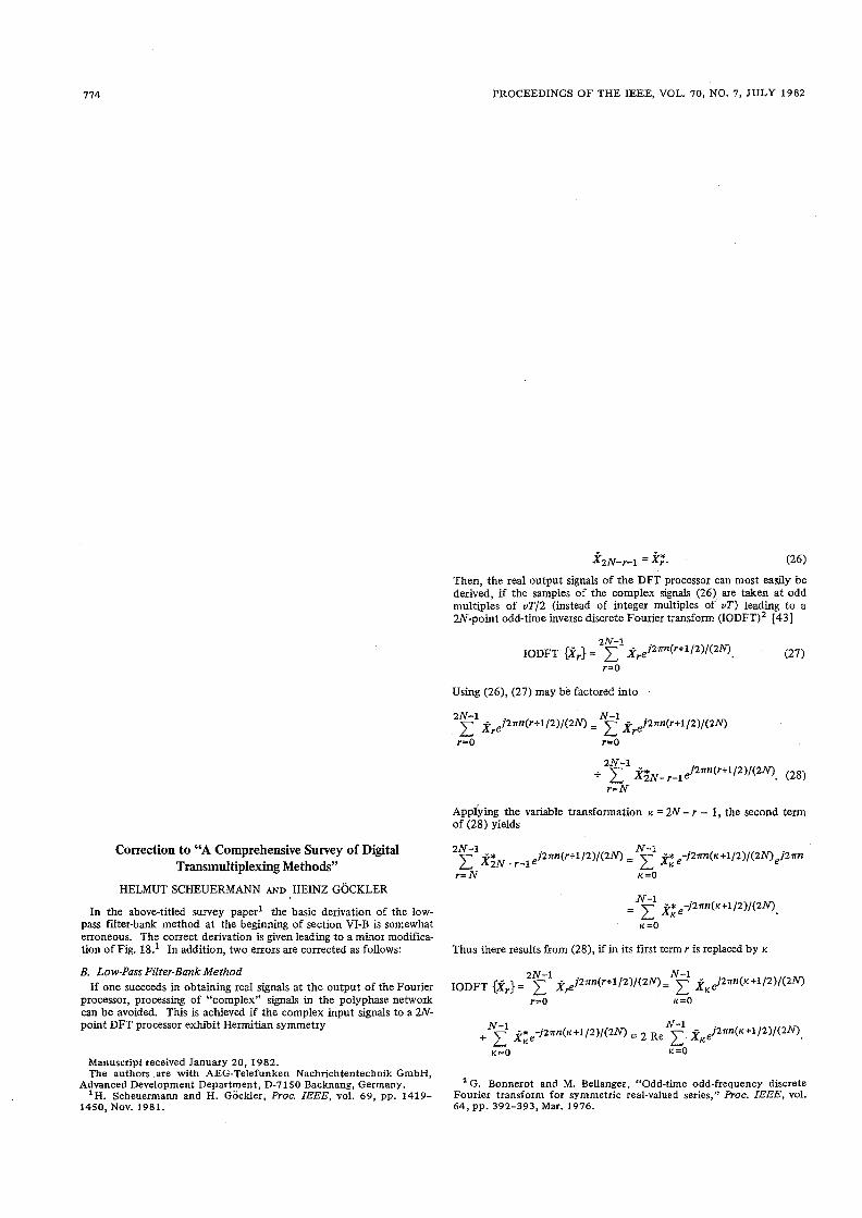
PROCEEDINGS OF THE IEEE, VOL. 70, NO. 7, JULY 1982
Correction to "A Comprehensive Survey of Digital Transmultiplexing Methods"
HELMUT SCHEUERMANN AND HEINZ GOCKLER
In the above-titled survey paper1 the basic derivation of the low- pass frlter-bank method at the beginning of section VI-B is somewhat erroneous. The correct derivation is given leading to a minor modifica- tion of Fig. 18.' In addition, two errors are corrected as follows:
B. Low-Pass Filter-Bank Method If one succeeds in obtaining real signals at the output of the Fourier
processor, processing of "complex" signals in the polyphase network can be avoided. This is achieved if the complex input signals to a W- point DFT processor exhibit Herrnitian symmetry
Manuscript received January 20, 1982. The authors are with AEG-Telefunken Nachrichtentechnik GmbH,
Advanced Development Department, D-7150 Backnang, Germany. 'H, Scheuermann and H. GocMer, Proc. ZEEE, vol. 69, p p . 1419-
1450, NOV. 1981.
Then, the real output signals of the DFT processor can most easily be derived, if the samples of the complex signals (26) are taken at odd multiples of vT/2 (instead of integer multiples of vT) leading to a W-point odd-time inverse discrete Fourier transfo~m (IODFT)~ 1431
Using (26) , (27) may b'e factored into
~pp iy ing the variable transformation K = 2N - r - 1, the second tern of ( 2 8 ) yields
Thus there results from (28) , if in its fust term r is replaced by K
a G. Bonnerot and M. Bellanger, "Odd-time odd-frequency discrete Fourier transform for symmetric real-valued series," Proc. ZEEE, vol. 64, pp. 392-393, Mar. 1976.

PROCEEDINGS O F THE IEEE, VOL.,70, NO. 7, JULY 1982
From this, the z-transform of the transmultiplexer output sequence is obtained in the natural sequential order of summation
and, accordingly, by interchanging the summation order
As a consequence, the IDFT processor in Fig. lgl must be replaced by a 2N-point IODFT processor.
Finally, two errors are indicated: The fust sentence of the last para- graph of p. 1432 should read: "Still another transmultiplexer, proposed by Tomlinson and Wong [48], [49], works according to the low-pass filter-bank method." Second, the author of 1631 is A. Fettweis.