chapter 8 soils & geology - county roscommon€¦ · soils. removal of entirety of geological...
TRANSCRIPT

Roughan & O’Donovan – AECOM Alliance N5 Ballaghaderreen to Scramoge Road Project
Consulting Engineers Environmental Impact Assessment Report
Ref: (14.155) Page 8/1
Chapter 8 Soils & Geology
8.1 Introduction This chapter considers and assesses the likely significant impacts with regard to Soils and Geology associated with both the construction and operational phases of the proposed road development. Measures to mitigate the likely significant adverse impacts of the road development are proposed, and residual impacts are described. The chapter initially sets out the methodology used (Section 8.2), describes the existing soils and geology environment (Section 8.3), examines the predicted impacts of the proposed development (Section 8.4), proposes mitigation measures (Section 8.5), and identifies residual impacts (Section 8.6).
8.2 Methodology
8.2.1 Legislation and Guidelines
This chapter is prepared having regard to the requirements of Section 50 Sub-section (2 and 3) of the Roads Act 1993 as amended, Directive 2011/92/EU (as amended by Directive 2014/52/EU), and with the following guidance:
National Roads Authority (NRA 2008) Environmental Impact Assessment of National Road Schemes – A Practical Guide,
National Roads Authority (NRA 2008) Guidelines on Procedures for Assessment and Treatment of Geology, Hydrology and Hydrogeology for National Road Schemes;
EPA, Guidelines on the Information to be contained in Environmental Impact Statements, 2002;
EPA, Advice notes on Current Practice (in the preparation of Environmental Impact Statements), 2003.
The following Draft Guidance documents which are currently on consultation have also been consulted:
Guidelines on the Information to be contained in Environmental Impact Assessment Reports, Draft May 2017;
Advice Notes for Preparing Environmental Impact Statements, Draft September 2015.
8.2.2 Consultation
Consultation was carried out with the relevant bodies as detailed below. Consultees contacted for the purposes of the study were:
Geological Survey of Ireland (GSI);
Department of Environment, Community and Local Government (DoECLG);
Local Authorities – In particular the Environment and Water Services Sections of Roscommon County Council
Consultation with all of the other specialists on the project team has been undertaken throughout the development of the project.
Roughan & O’Donovan – AECOM Alliance N5 Ballaghaderreen to Scramoge Road Project
Consulting Engineers Environmental Impact Assessment Report
Ref: (14.155) Page 8/2
8.2.3 Study Area and Baseline Data Collection
Data compilation of available published information was completed during the Constraints and Route Corridor Selection studies. Additional information has been compiled from the following sources:
Relevant pre-existing information from earlier schemes;
Feedback from consultations with statutory consultee’s, interested organisations and affected third parties;
A walkover reconnaissance survey of the road scheme in March 2015;
Results of geophysical surveys undertaken along the proposed road alignment (Minerex report reference 5938-005);
Findings of ground investigations (boreholes, rotary drill holes, trial pits and probes and in-situ and laboratory test data) along the proposed road alignment (IGSL report reference number 18382, Priority Geotechnics Ltd. Report No. PC8093 and Glovers Report Reference 06-975).
8.2.4 Walkover Survey
A walkover survey was undertaken along the length of the road scheme by the geotechnical team in March 2015 in order to assist in identification and assessment of the environmental impact of the scheme on the geological environment and on features of geological interest. Following changes to the proposed route alignment at Leggatinty and Lugboy additional site walkovers were undertaken in these areas during the ground investigation. The quality of information from the walkover survey was enhanced by indentifying specific sites and features of interest from existing information sources and aerial photographs.
8.2.5 Ground Investigations
Three separate ground investigations have been undertaken for the N5 Ballaghaderreen to Scramoge Road Project.
8.2.5.1 2007 Investigation
In May 2007, under the instruction of the Roscommon National Road Design Office, a dynamic probing investigation was carried out by Glover Site Investigations at specified locations to determine the depth and extent of soft ground. The site operations consisted of 417 dynamic probes within 36 separate locations identified during route selection as having suspected poor ground. Relevant data from this investigation was utilised to inform the scope of additional site investigations and to complete the overall site investigation data.
8.2.5.2 2008 Investigation
A Preliminary Ground Investigation was undertaken for the Strategic Corridor between October and November 2008. The investigation was carried out by Priority Drilling Ltd and directed by Roscommon NRDO. The scope of investigation was to determine the soil, bedrock and groundwater conditions and to establish the potential presence of any contaminants along the corridor. The field works comprised of 61 cable percussion boreholes, 20 rotary follow-on boreholes and 156 trial pits. In-situ testing and sampling consisted of Standard Penetration Testing (SPT) at regular intervals, with disturbed and undisturbed samples taken from boreholes for laboratory testing. Relevant data from this

Roughan & O’Donovan – AECOM Alliance N5 Ballaghaderreen to Scramoge Road Project
Consulting Engineers Environmental Impact Assessment Report
Ref: (14.155) Page 8/3
investigation was utilised to inform the scope of the most recent ground investigation undertaken. Findings of both of the above investigations were combined together in an Earthworks Assessment Report. This report was prepared by AGL Geotechnical Consulting Engineers in August 2009. This report assessed results from the dynamic probes, cable percussion boreholes, rotary core boreholes and trial pits to give an indication of material acceptability and soft ground depths along the N5 Strategic Corridor.
8.2.5.3 2015 – 2016 Investigation
The most recent ground investigation which commenced in May 2015 was completed in July 2016. The scope of this investigation was determined from analysis of previous ground investigation findings in relation to the preferred route, aerial photography and site walkovers performed by ROD – AECOM Alliance. The investigation objectives were to determine the subsurface conditions, the extent of soft ground, made ground, peat and likely depths to rock, rock strength and any suspected zones of karstification. The investigation was also designed to assess groundwater levels and to investigate the presence of any contaminants along the proposed route and assess the suitability of a number of possible material deposition areas close to the scheme. The fieldworks consisted of 124 cable percussion boreholes to determine the strength and compressibility of the overburden material, 98 rotary cores to determine the bedrock conditions and rock strength, 94 trial pits and 145 dynamic / hand probes. In-situ testing consisted of Standard Penetration Testing (SPT) undertaken at regular intervals, typically 1.5m. In-situ shear vanes were also undertaken in trial pits and boreholes. Bulk, disturbed, undisturbed and piston samples were taken from the boreholes. In areas of soft ground / peat a Russian Sampler was used to extract samples from the ground. In addition to the exploratory holes and in-situ testing, a Geophysical Survey was carried out by Minerex Geophysics Ltd. in 13 different locations. This survey was conducted to investigate areas of suspected karstification, soft ground conditions and deep cuts where shallow rock is likely to be encountered. The survey was supplemented with additional cable percussion holes, rotary core holes and dynamic probes to confirm any anomalies in the results, as recommended by the geophysics specialists. The location and results of the 2015/16 Investigation are presented on Fig.8.1 to 8.25 in Volume 3.
8.2.6 Limitations to Access During Investigation
Due to the presence of forestry, access of technical equipment to some of the specified borehole / trial pit / dynamic probe and geophysics locations was not possible. In these cases, alternative locations and techniques were agreed with Roscommon County Council.
8.2.7 Impact Assessment Methodology
The potential impact of the proposed road development on the soils and geology environment has been assessed by classifying the importance of the relevant attributes and quantifying the likely magnitude of any impact on these attributes. The rating criteria for assessing the importance of geological features within the study

Roughan & O’Donovan – AECOM Alliance N5 Ballaghaderreen to Scramoge Road Project
Consulting Engineers Environmental Impact Assessment Report
Ref: (14.155) Page 8/4
area are outlined in Table 8.1 whilst the rating criteria for quantifying the magnitudes of impacts are outlined in Table 8.2. The rating of potential environmental impacts on the soils and geology environment are based on the matrix presented in Table 8.3 which take account of both the importance of an attribute and magnitude of the potential environmental impacts of the proposed road development on it. These impact ratings are in accordance with impact assessment criteria provided in the EPA publication Guidelines on the Information to be contained in Environmental Impact Statements (EPA, 2002). The impact assessment methodology is also in accordance with the guidance outlined in Section 5.4 of the NRA’s Guidelines on Procedures for Assessment & Treatment of Geology, Hydrology & Hydrogeology for National Roads NRA (2008). Impact categories, impact duration and type/nature of impacts have been taken into account in this assessment as per those guidelines.
8.2.8 Limitations in the Methodology and Gaps in Information
There were no limitations in the methodology or significant gaps in information which affected the assessment. Table 8.1 Criteria for Rating Site Importance
Importance Criteria Typical Example
Very High
Attribute has a high quality, significance or value on a regional or national scale.
Degree or extent of soil contamination is significant on a national or regional scale.
Volume of peat and/or soft organic soil underlying route is significant on a national or regional scale.*
Geological feature rare on a regional or national scale (NHA).
Large existing quarry or pit.
Proven economically extractable mineral resource
High
Attribute has a high quality, significance or value on a local scale. Degree or extent of soil contamination is significant on a local scale.
Volume of peat and/or soft organic soil underlying route is significant on a local scale.*
Contaminated soil on site with previous heavy industrial usage.
Large recent landfill site for mixed wastes.
Geological feature of high value on a local scale (County Geological Site).
Well drained and/or highly fertility soils.
Moderately sized existing quarry or pit.
Marginally economic extractable mineral resource.
Medium
Attribute has a medium quality, significance or value on a local scale.
Degree or extent of soil contamination is moderate on a local scale.
Volume of peat and/or soft organic soil underlying route is moderate on a local scale.*
Contaminated soil on site with previous light industrial usage.
Small recent landfill site for mixed wastes.
Moderately drained and/or moderate fertility soils.
Small existing quarry or pit.
Sub-economic extractable mineral resource.

Roughan & O’Donovan – AECOM Alliance N5 Ballaghaderreen to Scramoge Road Project
Consulting Engineers Environmental Impact Assessment Report
Ref: (14.155) Page 8/5
Importance Criteria Typical Example
Low
Attribute has a low quality, significance or value on a local scale.
Degree or extent of soil contamination is minor on a local scale.
Volume of peat and/or soft organic soil underlying route is small on a local scale.*
Large historical and/or recent site for construction and demolition wastes.
Small historical and/or recent landfill site for construction and demolition wastes.
Poorly drained and/or low fertility soils.
Uneconomically extractable mineral resource.
* relative to the total volume of inert soil disposed of and/or recovered
Table 8.2 Criteria for Rating the Impact Magnitude at EIAR Stage –
Estimation of Magnitude of Impact on Soil/Geology Attribute
Magnitude of Impact
Criteria Typical Examples
Large Adverse
Results in loss of attribute.
Loss of high proportion of future quarry or pit reserves.
Irreversible loss of high proportion of local high fertility soils.
Removal of entirety of geological heritage feature.
Requirement to excavate / remediate entire waste site.
Requirement to excavate and replace high proportion of peat, organic soils and/or soft mineral soils beneath alignment.
Moderate Adverse
Results in impact on integrity of
attribute or loss of part of attribute.
Loss of moderate proportion of future quarry or pit reserves.
Removal of part of geological heritage feature.
Irreversible loss of moderate proportion of local high fertility soils.
Requirement to excavate / remediate significant proportion of waste site.
Requirement to excavate and replace moderate proportion of peat, organic soils and/or soft mineral soils beneath alignment.
Small Adverse
Results in minor impact on integrity of attribute or loss
of small part of attribute.
Loss of small proportion of future quarry or pit reserves.
Removal of small part of geological heritage feature.
Irreversible loss of small proportion of local high fertility soils and/or high proportion of local low fertility soils.
Requirement to excavate / remediate small proportion of waste site.
Requirement to excavate and replace small proportion of peat, organic soils and/or soft mineral soils beneath alignment.
Negligible
Results in an impact on attribute but of insufficient
magnitude to affect either use or
integrity
No measurable changes in attributes.
Minor Beneficial
Results in minor improvement of attribute quality
Minor enhancement of geological heritage feature.

Roughan & O’Donovan – AECOM Alliance N5 Ballaghaderreen to Scramoge Road Project
Consulting Engineers Environmental Impact Assessment Report
Ref: (14.155) Page 8/6
Magnitude of Impact
Criteria Typical Examples
Moderate Beneficial
Results in moderate
improvement of attribute quality
Moderate enhancement of geological heritage feature.
Major Beneficial
Results in major improvement of attribute quality
Major enhancement of geological heritage feature.
Table 8.3 Impact Assessment Criteria
Magnitude of Impact Description
Imperceptible An impact capable of measurement but without noticeable consequences
Slight An impact that alters the character of the environment without affecting its sensitivities
Moderate An impact that alters the character of the environment in a manner that is consistent with existing or emerging trends
Significant An impact, which by its character, magnitude, duration or intensity alters a sensitive aspect of the environment.
Profound An impact which obliterates all previous sensitive characteristics
8.3 Existing Environment
8.3.1 Introduction
The following sections provide an overview of the regional geological environment with details of available site investigation information within the EIAR study area. Bedrock geology, subsoils and geological features of importance such as karst features are documented here. The project is subdivided into discrete sections A, B, C and D which are located between the following chainage extents:
Section A: Ch. 1+000m – Ch. 5+697m
Section B: Ch. 10+000m – Ch. 24+200m
Section C: Ch. 30+000m – Ch. 40+542m
Section D: Ch. 50+000m – Ch. 53+970m
8.3.2 Regional Overview of Agricultural Soils, Subsoil and Solid Geology
The proposed road development extends from the east of Ballaghaderreen at a tie-in with the recently constructed N5 Ballaghaderreen Bypass to Scramoge in County Roscommon. The geology of the area is dominated by 330 million year old limestones from the carboniferous period. These carboniferous limestones are predominantly well bedded, horizontal layers of a remarkably uniform nature. Geological maps from the GSI were reviewed to obtain an overview of the bedrock geology traversed by the proposed road alignment. There are 4 main rock units identified: Visean Limestone Formation, Ballymore Limestone Formation, Boyle Sandstones and Fearnaght Sandstone Formation, all four are Carboniferous in age.

Roughan & O’Donovan – AECOM Alliance N5 Ballaghaderreen to Scramoge Road Project
Consulting Engineers Environmental Impact Assessment Report
Ref: (14.155) Page 8/7
The topography of the region is an indication of the geology and can be used as a guide for mapping the various rock types. Generally, sections A and B consist of a landscape that is gently undulating while sections C and D consist of a drumlin landscape. In Section C and D an area of ribbed moraines exist which is known as the Mid Roscommon Ribbed Moraines, extending over an area of approximately 200km2. Table 8.4 Bedrock Geology Encountered Along Proposed Road Section
(West to East)
Chainage Bedrock type Formation
1+000 – 12+000 14+250 – 35+000 38+000 – 53+200
Dark grey to black thinly bedded cherty limestone
VIS Visean Limestone
12+000 – 14+500 Sandstone, siltstone, black mudstone
WG Boyle Sandstone
35+000 – 38+000 Dark fine grained limestone and shale
BM Ballymore Limestone
53+200 – 54+350 Conglomerate & red Sandstone FT Fearnaght Sandstone
8.3.3 Solid Geology
The available information on the 1:100,000 scale Geological Survey of Ireland map of the area (Geological Survey of Ireland, 1:100,000 Map sheet 12) shows the proposed route is predominantly characterised by Visean limestone. The Boyle sandstone formation was identified in the vicinity of Frenchpark. In general the rock encountered during the ground investigation is consistent with the published geology for the area. Mudstone and siltstone, which are considered argillaceous rocks, were encountered in BH417 at Ch. 12+150m between 5.6m and 8.3m and in BH420A at Ch. 13+950m between 3m and 7m approximately. Apart from these occurrences, none of the rock encountered during the ground investigation is likely to be argillaceous. Sandstone was recorded in the majority of rotary core holes between Ch. 12+000 and 15+000m. Limestone can potentially be dissolved by rainwater over very long durations. It is often highly permeable and can result in eroded limestone (karst) areas. The underlying bedrock of Carboniferous Limestone is noted to be karstified. There are a number of known karst features located within close proximity to the proposed development as documented in the Geologic Survey of Ireland Karst Database and Meehan and Parkes (2014). Potential areas of known karst features have been identified along the scheme. A number of turloughs exist throughout central and north Roscommon. These basins fill with groundwater in winter and dry out in summer as the water table lowers. Table 8.5 Solid Geology Along the Proposed Route
System Series Formation Name and Rock Description
Carboniferous Dinantian Visean Limestone Formation – Dark grey to black thinly bedded cherty limestone
Ballymore Limestone Formation – Dark fine grained limestone and shale

Roughan & O’Donovan – AECOM Alliance N5 Ballaghaderreen to Scramoge Road Project
Consulting Engineers Environmental Impact Assessment Report
Ref: (14.155) Page 8/8
System Series Formation Name and Rock Description
Boyle Sandstone Formation – Sandstone, siltstone, black mudstone
Fearnaght Sandstone Formation – Conglomerate & red sandstone
8.3.4 Karst Areas
Much of the underlying bedrock of carboniferous limestone is noted to be at risk of karst development and geological features associated with karstification. A preliminary assessment of all reported and known karst features in proximity to the route has been conducted based on the following:
Karst Features such as sinkholes, turloughs, caves, etc. reported in relevant engineering reports, GSI database, or the publication Meehan & Parkes (2014).
Evidence of karst development in subsoil or bedrock conditions shown in boreholes or geophysical tests, such as very loose unstable soils, clay filled or open voids in bedrock, or large local variations in depth to, or character, of bedrock, (particularly beneath structures).
Evidence of surface erosion features based on site reconnaissance; A number of areas have been identified during site walkovers and ground investigations that indicate potential risk areas of karstification along the proposed route. These are summarised as follows and are indicated on drawing 03-600-GI-501 to 503:
(i) Leggatinty (Ch. 11+000 – 11+700)
A significant karst area with a number of known karst features is located at Leggatinty, approximately 475m to the north of the proposed route. These are indicated on the Geological Survey of Ireland (GSI) karst features mapping. One of these features is an underground stream cave known as Pollnagran, which stretches underground for a distance of approximately 750m in a northwest direction away from the proposed route. The cave has an entrance in a shallow blind valley where a surface stream sinks underground. Another stream combines with this underground stream a short distance into the cave (Meehan & Parkes 2014). The proposed route does not cross this underground stream but passes around 475m to the south.
Plate 8.1 Karst features and GI at Leggatinty

Roughan & O’Donovan – AECOM Alliance N5 Ballaghaderreen to Scramoge Road Project
Consulting Engineers Environmental Impact Assessment Report
Ref: (14.155) Page 8/9
(ii) Kilvoy and Corry East (Ch. 18+400 – 19+300)
A number of surface karst features (swallow holes) have been identified within this area in close proximity to the proposed route. One swallow hole is located within the footprint of the proposed route at Ch. 19+050. A detailed ground investigation including rotary coring and a geophysical survey of this area has been undertaken to identify potential for instability. Groundwater was not observed during drilling works but it was noted that the rock encountered was highly fractured with clay infill recorded in a number of locations. Loss of drill fluid was observed during rotary drilling. No significant voids were encountered in the rock.
Plate 8.2 Karst features and GI at Kilvoy and Corry East
Superficial soils within this area generally consist of firm to stiff clay, with soft silt present in BH428 to a depth of 2m and soft clay present to a depth of 1m in BH430A and BH430B.
(iii) Cloonyeffer (Ch. 20,450m)
Approximately 65m to the south of the proposed route at this location, there is a known karst feature as identified on the GSI karst features mapping. This karst feature consists of a sinking stream which drains into a pond with no apparent outlet. BH434 undertaken at Ch. 20+450m, just north of the route indicated zones of loss of core recovery of between 200mm and 880mm thick between 9 and 12m depth indicating potential fractures / voids in the bedrock. Clay, sand and gravel infill within cavities in the bedrock were recorded. The superficial deposits in this area consist of firm to stiff clay. No evidence of soft or loose material was observed within this area.
Plate 8.3 Karst features and GI at Cloonyeffer

Roughan & O’Donovan – AECOM Alliance N5 Ballaghaderreen to Scramoge Road Project
Consulting Engineers Environmental Impact Assessment Report
Ref: (14.155) Page 8/10
(iv) Portaghard (Ch. 3+450m – 4+100m)
At Ch. 3+450m, approximately 100m to the north of the proposed road is a further possible area of karstification. A number of surface karst drainage features, have been identified at this location. Another karst surface drainage feature was identified at Ch. 4+100m approximately 50m to the south of the proposed route. This area remains one of low risk for future development of surface features.
(v) Tullyloyd (Ch. 34+350m)
There is a potential area of karstification which has been identified approximately 150m south of the proposed road at Ch. 34+350m where a swallow hole has been noted.
(vi) Seasonal Lakes and Turloughs
A number of turloughs exist throughout central and north Roscommon. These basins fill with groundwater in winter and dry out in summer as the water table lowers. A turlough feature of this type is noted adjacent to a fill segment along Section C situated at the bottom of the steep sided slopes at Ch. 37+520m north of Annaghmore Lough.
There are no bridge or culvert structures directly underlain by observed karst in any of the six potential karst areas described above. At the Carricknabraher River (Ch. 10+120) crossing, BH410 indicated potential for karst development with weathered rock contributing to core loss between 12.01m – and 12.11m depth. Also at the Scramoge River (Ch. 52+840m), BH479 indicated weathered rock contributing to core loss between 20.4m and 20.7m and also between 21.5m and 23m. Mitigation proposals for design of structural foundations are indicated in Section 8.5. In addition to the specific locations identified above, there is evidence from the rotary core logs that karstification of the underlying bedrock is present throughout the scheme. The following indicators of karstification were noted in rotary core logs:
Loss of drill fluid;
Voids in rock infilled with Clay;
Core loss / voids. These occurrences may potentially lead to the development of surface karst features that represent medium to low risk where further mitigation is not currently expected. More detail on these karst features can be found in Chapter 9 Hydrogeology.
8.3.5 Soils and Subsoils
8.3.5.1 Subsoils
Fine grained glacial till is the predominant soil type present with layers of coarse grained glacial till sporadically present near the base of the strata overlying bedrock. Isolated deposits of alluvium and peat were also encountered.
8.3.5.2 Made Ground
Three localised areas of Made Ground which were identified at Ch. 2+270m in TP303 to a depth of 1.7m, on the diverted L-6044 (north) at Ch. 50+000 in TP 345A to a depth of 0.5m and at Ch. 35+150m to a depth of 0.8m in TP379. The material in TP303 was described as firm brown sandy gravelly clay while the material in TP345A

Roughan & O’Donovan – AECOM Alliance N5 Ballaghaderreen to Scramoge Road Project
Consulting Engineers Environmental Impact Assessment Report
Ref: (14.155) Page 8/11
was described as loose grey sandy angular gravel. Material in TP379 was indicated as made ground comprised of loose cobbles with clay. The majority of exploratory holes undertaken in the ground investigation were conducted in greenfield sites. No observations of contamination were observed at these locations or based on Murphy Suite laboratory test results (Murphy Suite test results are given in the Ground Investigation Factual – N5 Ballaghaderreen to Scramoge Project – Factual Report (18382). Fill material from Laragan Quarry, located at Cregga is noted to have been used to infill an area of land adjacent to the turlough between Ch. 36+750m and 37+100m. This material is located at a distance greater than 100m from the proposed road. At Ch. 39+500m, there is an old disused quarry located about 50m south of the proposed route. This quarry has been backfilled. BH471 and TP344B were carried out along the proposed route in close proximity to this area and did not identify any evidence of made ground or contamination. At Cregga Hill in Cuilrevagh, near Laragan Quarry, a burial pit for carcusses of burnt meat exists as a result of a fire in a meat plant in Ballaghadereen. This is located approximately 50m north of the proposed development at Ch. 36+300m approximately. Nearby boreholes within this area did not indicate any evidence of contamination.
8.3.5.3 Peat / Organic Soil Layers
Throughout the scheme, peat deposits have been identified along the route in numerous areas. They are situated mainly in bog areas in Sections A & B and in areas of low lying ground between drumlin peaks in Sections C & D. Site investigation information obtained indicates depths of peat encountered between 0.5m to 5.0m along sections of the proposed route.
Peat was encountered between Ch. 5+000m and Ch. 5+700m over a total length of approximately 700m. Peat was encountered to a maximum depth of 2.8m in BH494. Peat is underlain by 2.3m of soft grey silt (BH408) as it approaches the R361. Significant peat deposits were encountered between Ch. 10+250 to Ch. 12+600 in the area of Leggatinty. This 2350m length of peat ranges between depths of 0.5m to 2.9m and generally overlies firm to stiff gravelly silt. Ch. 14+000 to 15+650m revealed peat extending to depths of between 2.0m to 4.7m. This length of 1.65km section has been investigated thoroughly with a grid system of dynamic probes carried out and trial holes, boreholes and geo-physics undertaken to identify the extent of peat deposits along the proposed route. In general the peat deposits are underlain by very soft to soft silts and loose gravels. BH421 recovered 4.7m of peat overlying 1.3m of soft silt to a depth of approximately 6.0m. Peat was also encountered between Ch. 16+400 to 17+600m over an approximate length of 1.2km with a maximum depth of 2.7m of peat in TP058. Due to an area of dense woodland cable percussion borehole access was not possible between Ch. 16+700m and Ch. 17+250m. Hand probes were carried out within the forested areas while boreholes were advanced at each end of the forested area. Hand probes indicated a maximum of 3.3m depth of soft ground within the area of forestry. In Section C, east of the N61 an area of peat was identified from the findings of the ground investigation between Ch. 30+700m to Ch. 31+600m. Depths of peat ranged

Roughan & O’Donovan – AECOM Alliance N5 Ballaghaderreen to Scramoge Road Project
Consulting Engineers Environmental Impact Assessment Report
Ref: (14.155) Page 8/12
from 1.1m to a maximum depth of peat of 3.1m. Borehole BH440 indicated a depth of 6.1m of soft material with a makeup of 3.1m of peat and 3m of soft sandy silt. Peat deposits in this area are generally underlain by very soft to soft silts. Investigation in this area included a geophysics transect from high ground to low ground adjacent to the Owenur River, perpendicular to the alignment as seen in figure 12.3.1. This gives an indication of how the depth of peat increases in close proximity to the Owenur River.
Plate 8.4 Geophysics Transect at Lurgan
Ground investigation carried out in Section D identified two areas of significant peat deposits. Between Ch. 51+000m to Ch. 51+650m, on either side of the Strokestown River peat depths of between 1.1m and 3.6m were recorded. BH 476 indicates a depth of 8.3m of soft ground made up of 3.6m peat overlying 4.7m of soft silt. BH501 also indicates a depth of peat of 3.6m depth. Geophysics results show that this deep pocket is approximately 50m in length with the remaining 550m in this area having an average depth of peat of 2m. Peat was also encountered in Section D between Ch. 52+750 and Ch. 53+150. Boreholes and trial pits were undertaken within this area adjacent to the Scramoge River. A 700mm thick peat layer was recorded starting at a depth of 2.3m in BH480 and a 600mm layer starting at 0.5m in TP350, underlain by soft sandy clay to depths of 4 to 5.4m. Peat was recorded between ground level and 1m depth in BH60.
Location of
proposed road

Roughan & O’Donovan – AECOM Alliance N5 Ballaghaderreen to Scramoge Road Project
Consulting Engineers Environmental Impact Assessment Report
Ref: (14.155) Page 8/13
8.3.5.4 Alluvium Fine Grained
Within Section B there are several areas of alluvial deposits encountered along the route. These are generally confined to limited zones, typically adjacent to watercourses. At Carricknabraher River at Ch.10+150 a layer of soft grey sandy silt was identified in BH409 & BH410 along the banks of the river with an approximate thickness of 1.5m of soft alluvial material. Soft alluvial material was also encountered in BH408 below peat, between depths of 1.9m and 4.2m. Alluvial deposits were also encountered between Ch. 11+200 to Ch. 11+700 in the area of Leggatinty in close proximity to a stream which is near the proposed route. These were generally recorded below peat deposits below an average depth of 2m. The thickness of alluvial material encountered was generally between 1 and 2m. The ground investigation in the area of Drummin on opposite sides of the Owennaforeesha River, located between Ch. 14+250m to 15+300m, indicated an average thickness of 1.5m of alluvial material underlying an average thickness of 3.5m of peat. The maximum depth of soft alluvium below the ground surface was 6.0m. A number of layers of alluvial granular material described as silty gravel were also encountered within this area. In Section C between Ch. 30+700 and 30+950 a band of alluvial material of up to 3.0m was encountered below peat in BH439 and BH440 located on either side of the Owenur River, in a low lying area surrounded by drumlins. BH440 indicated 3.0m of alluvium described as very soft gravelly silt underlying 3.1m of peat. Limited areas of alluvial deposits were encountered along the route in Section D, confined to the areas around the Strokestown and Scramoge rivers. Adjacent to the Strokestown River at Ch. 51+200m, BH476 recorded very soft alluvial material underlying 3.6m of peat to a maximum depth of 8.3m while BH501 indicated soft alluvium underlying 3.6m of peat to a depth of 5.8m. Between Ch. 52+750m – Ch. 53+150m, adjacent to the Scramoge River, BH479 recorded soft sandy gravelly clay between 0 and 2.7m depth. BH480 recorded soft brown clay between 0 and 2.3m and loose sand between 3.0 and 3.7m.
8.3.5.5 Lacustrine Deposits (Marl)
In Section C between Ch. 33+650 – 33+750m, adjacent to Clooncullaan Lough, BH497 indicated very soft white / cream, sandy, calcareous silt to a depth of 7.9m. This was the only borehole during the investigation that indicated soft ground to a significant depth within this area with a number of probes identifying soft ground within this area to approximately 1.5m depth.
8.3.5.6 Glacial Till
Glacial deposits are widespread throughout the route. These range from sandy gravelly Clays/Silts to gravelly Sands and Gravels with cobbles and are shown on the GSI Teagasc Subsoil Map of County Roscommon to be Tills generally derived from Visean Limestone. The constituent parts and matrix proportions of these deposits vary considerably. For engineering purposes these deposits are divided into Glacial Till fine-grained and Glacial Till coarse-grained in accordance with BS5930 which defines fine grained soils as containing more than 35% fines passing the 63 micron sieve size. In areas where there was uncertainty regarding the engineering description of the Glacial Till or where the exploratory holes were advanced through rotary open hole methods, without obtaining samples, the Glacial Till was described as undifferentiated. Fine grained glacial till (GF) is the predominant soil type present

Roughan & O’Donovan – AECOM Alliance N5 Ballaghaderreen to Scramoge Road Project
Consulting Engineers Environmental Impact Assessment Report
Ref: (14.155) Page 8/14
with layers of coarse grained glacial till (GC) sporadically present near the base of the strata overlying bedrock.
8.3.6 Mineral Aggregate Resources along the Proposed Development
There are a number of quarries in the vicinity of the scheme which may be utilised in the sourcing of fill material including:
Hanly Bros. Ltd. Quarry, Laragan – located approximately 200m north of the proposed development at Cuilrevagh (Ch. 37+200m);
Roadstone Quarry Boyle – located 3km east of Boyle along the N4;
Roadstone Quarry, Castlemine– located east of the N61, approximately 6km to the north of Roscommon Town;
Ballyfeeny Rock Quarry – located on the R371 3km north of Scramoge. Fig. 8.25 in Volume 3 shows the location of authorised / registered quarry sites in the vicinity of the proposed development.
8.3.7 Geological Heritage Areas
Mid Roscommon Ribbed Moraine To the west and northwest of Slieve Bawn, between Elphin and Tulsk, an area of ribbed moraines exist which cover an area of approximately 200km2. These ribbed moraines contain a number of superimposed drumlins on their crests, and the area has traditionally been known as the southwestern-most extreme of the drumlin belt. This ribbed moraine field is unusual in its size and discreteness, but being interspersed with deep peat means the features are quite striking. The features are generally 6km – 8km long and 1km or so wide. They attain a maximum height of around 35m and are usually 25m or so in elevation. From the commencement of Section C at the proposed N61 roundabout (Ch. 30+000) through to the end of Section D at Ch. 54+100m, the proposed route advances through this area of ribbed moraines. The topography can be described as a drumlin landscape with a number of sloped sections. Pollnagran Stream Cave Pollnagran is a cave located approximately 1.5km to the south of Frenchpark and approximately 400m to the north of the proposed route at Leggatinty. This stream cave is approximately 750m long and is the only known active stream cave in county Roscommon. The cave has an entrance in a shallow blind valley where the surface stream disappears underground. A second stream combines with the first a short distance in, the cave is then a single linear passage trending northeast (away from the proposed route) until it becomes impassable. The underground stream follows a single bedding plane down a very shallow dip of 2 – 3 degrees.
8.4 Predicted Impacts An analysis of the predicted impacts of the proposed road development on soils and geology during construction and operation is presented in the following sections. The assessment considered geological features identified within 250m of the development boundary of the proposed road development and follows the requirements of the National Roads Authority (NRA 2008) Guidelines on Procedures for Assessment and Treatment of Geology, Hydrology and Hydrogeology for National Road Schemes.

Roughan & O’Donovan – AECOM Alliance N5 Ballaghaderreen to Scramoge Road Project
Consulting Engineers Environmental Impact Assessment Report
Ref: (14.155) Page 8/15
8.4.1 Do Nothing Scenario
In the case where the road was not to be developed there would be no resulting impacts on the Soils or Geology along the site of the proposed road development. The impact would therefore be neutral.
8.4.2 Do Something Scenario (Construction Phase Impacts)
8.4.2.1 Construction Dewatering
In areas of significant cuts temporary drainage will be required to allow excavation in a dry environment, locally lowering the ground water table. The impact of this drainage is addressed in Chapter 9 Hydrogeology. Where till is located the dewatering will be minimal, whereas in areas with significant thickness of gravels and sands this may be more significant. In areas of karstification it is important to note that any change in the normal groundwater patterns may cause potential instabilities. Such lowering of the water table during construction in karst areas could potentially lead to instabilities. However, based on the findings of the ground investigation it is not likely that construction dewatering will be required in any potential karst areas. Table 8.7 and 8.8 show the significant cuts. These tables describe the soils, subsoil and bedrock and whether water was encountered during site investigations. Impacts are expected to be temporary or slight. Permanent impacts are addressed in Chapter 9 Hydrogeology. Although no construction dewatering is anticipated in karst areas, should this arise during construction it has the potential to be significant.
8.4.2.2 Slope Stability
Cuttings through Glacial Tills and rock vary along the scheme up to a maximum depth of 27m. The majority of cut slopes consist of both glacial till and bedrock. The varying properties of glacial till and the presence of groundwater will result in seepage from slopes which can lead to erosion and instability of slopes unless mitigations are provided. Tables 8.8 and 8.9 provide the depths of glacial till encountered in areas of cut. There is a potential risk of slope instability during construction if unexpected conditions are encountered. This will be monitored and addressed as required and therefore the temporary impact is considered to be Slight.
8.4.2.3 Rock Excavation Methods
In areas of significant cut, rock will be encountered which requires removal. The method of removal can range from digging the material out with a bucket of an excavator, to blasting, which can have significant noise and vibration impacts associated with it. The noise and vibration impacts associated with blasting are discussed in more detail in Chapter 12. Blasting is likely to be employed at the 27m deep cut at Cregga (Ch. 35+100m – 36+470m) and potentially in other localised areas where hard rock is revealed during excavation to formation level. Despite its proximity to the turlough, the rock at Cregga was not found to be karstified. The only other areas of rock blasting are anticipated to be limited to a small number of locations which are not in close proximity to known karst features and hence the temporary impacts are considered to be slight.

Roughan & O’Donovan – AECOM Alliance N5 Ballaghaderreen to Scramoge Road Project
Consulting Engineers Environmental Impact Assessment Report
Ref: (14.155) Page 8/16
The area between Ch. 18+400m and 19+300m is noted as being an area of karstification with a number of swallow holes present at the ground surface level, one of which occurs within the proposed road footprint at Ch. 19+050m. In this area of karstification the maximum cut depth is 4.2m deep and is not expected to cut into the bedrock. Beyond this area, excavation in bedrock is required and is likely to be carried out by hydraulic breaking. In areas of karstification, it is important to note that any excavation of bedrock may lead to potential instabilities. Although no excavation of karstified rock is anticipated, should this arise during construction it has the potential to be significant.
8.4.2.4 Importation and Deposition of Materials
The proposed road development will require excavation of materials from cuts and importation, deposition of materials for embankments and removal of excess unsuitable material into material deposition areas. All materials excavated from cuts during the ground investigation have been assessed for re-use as general fill. Results from classification testing, grading, and moisture contents have led to the following assessment of re-use acceptability proportions: 95% for the deposits of clean sand and gravel found along the proposed route and 50% - 70% for the sandy gravelly Clays and gravelly Sands which are encountered over the majority of the site. The lower proportions of acceptability occur in the wetter deposits in the top 1 – 2m below ground surface which are more readily influenced by prevailing weather conditions and deeper localised zones around water-bearing silty sand / gravel lenses. Below 2m depth the higher acceptability percentage applies in fine grained glacial tills. Approximately 25% of the fine glacial till may be feasible for improvement by addition of lime. The predicted impact on soils and geology of importation and removal of material from the site is considered to be slight to moderate given that economic extraction from several quarries is ongoing in close proximity to the route.
8.4.2.5 Ground Improvement
Areas of soft, highly compressible or organic soil will not be suitable as foundations. In such circumstances consideration will be given to ground improvement measures such that a solution is developed in line with the design criteria to be stated in the Works Requirements, for the settlement and stability of earthworks. The method of ground improvement must also consider the construction programme, and the available time for completion or phasing of the works and the influence on secondary settlement rate. Typical methods adopted may consist of one of more of the following solutions:
Excavate and Replacement;
Surcharging;
Vertical Drainage Measures;
Basal Reinforced Earthworks;
Staged Construction Techniques;
Limiting Rates of Construction;
Pile Supported Embankment. Where the extent and depth of soft or organic soils is limited to less than approximately 6-7m deep, it is recommended that the most economic solution is either full or partial excavation and replacement with acceptable fill. The class of fill

Roughan & O’Donovan – AECOM Alliance N5 Ballaghaderreen to Scramoge Road Project
Consulting Engineers Environmental Impact Assessment Report
Ref: (14.155) Page 8/17
to be used will depend upon the location of the groundwater table. Excavation and replacement solutions may be feasible to greater depths but this will be dependent upon the prevailing ground and groundwater conditions, temporary support measures adopted plus the proximity of existing infrastructure and available working space. Where the extent and depth of soft soils is greater and where sufficient time exists in the construction programme, surcharge may be adopted to reduce the time required to achieve substantial completion of primary consolidation settlement for the final permanent embankment height. Alternatively where insufficient time is available to achieve this, vertical drainage measures may be considered to accelerate consolidation settlement to within acceptable post construction limits. In all cases partial excavation of the organic peat soils will be required followed by surcharge, with or without vertical drains and basal reinforcement depending on the construction programme available and specific properties of the calcareous marl and alluvial soils left in place. Settlement monitoring will be undertaken during and post construction to monitor the stability and performance of embankments. An alternative to surcharging would be the construction of a piled embankment. A pile supported embankment will typically involve the driving of steel H-piles, pipe piles or precast concrete piles to bedrock or alternatively bored piles socketed into bedrock, depending on detailed design preferences of the construction team. Pile spacings typically vary from 2m to 2.5m on a square grid layout. Following installation of the piles, pile caps would be fixed to the top of the piles. The pile embankment may need to be constructed in stages to allow monitoring and mitigate stability concerns. Piezometers (vibrating wire) will be installed to monitor pore water pressures during construction. There are three areas where as an alternative to excavation and/or surcharge, piled embankments may be considered. The first is between Ch. 13+800m and Ch. 15+700m the embankment height ranges from 2.0m to 6.4m. Results of the investigation outlined peat deposits of between 2.0m and 4.7m overlying soft silt. The most critical borehole within this area indicated peat overlying soft silt to a depth of 6.0m. Rock is likely to be encountered below a depth of 9m. The second area the potential for a piled embankment or ground improvement method occurs is between Ch. 33+650 and Ch. 33+750m where BH197 indicates a depth of 7.9m of soft material and its proximity to Clooncullaan lough may result in a preference for piling. The third such area is the embankment at Vesnoy between Ch. 51+100m to 51+250m, where an embankment of maximum height of 7.8m is proposed. BH476 and geophysics within this area identified a deep pocket of peat of 3.6m overlying 4.7m of alluvial material. This depth of soft ground may result in a preference for a piled construction method to stabilise the soils. Where piled embankment construction is selected two options can be considered for the load transfer platform.
(i) A reinforced concrete slab could be cast using the pile caps as support with a concrete thickness of approximately 300mm to 500mm to provide a safe load transfer and distribution. From this load transfer platform the embankment can be constructed using traditional methods.
(ii) An alternative load transfer platform can be constructed using geogrids & geotextiles known as a geosynthetic-reinforced pile-supported embankment.

Roughan & O’Donovan – AECOM Alliance N5 Ballaghaderreen to Scramoge Road Project
Consulting Engineers Environmental Impact Assessment Report
Ref: (14.155) Page 8/18
Above the pile heads, the reinforcement of one or more layers of geosynthetics (mostly geogrids) is placed.
If all of the deep deposits are excavated and replaced, and no alternative ground improvement or piled embankments are utilised then the total volume of peat, alluvium and lacustrine deposits to be excavated would be approximately 740,000m3. The treatment of the excavated material is described in Section 8.5. The impact magnitude on soils and geology of the proposed ground improvements is considered to be minor beneficial due to the reduction of excavation and fill quantities.
8.4.2.6 Sourcing of Materials
Depending on the strategies adopted by the contractor, there is the potential for a moderate deficit of material for the construction of the earthworks. In addition road pavement and concrete will be required There are a number of quarries in the vicinity of the scheme which may be utilised in the sourcing of this material as detailed in Section 8.3 above. Only those quarries that conform to all necessary statutory consents may be used in the construction phase. The impact on soils and geology of sourcing materials from existing authorised / licensed quarries is considered to be Slight.

Roughan & O’Donovan – AECOM Alliance N5 Ballaghaderreen to Scramoge Road Project
Consulting Engineers Environmental Impact Assessment Report
Ref: (14.155) Page 8/19
Table 8.6 Earthworks Volumes Assuming Full Excavation and Replacement of Soft Ground
1 2 3 4 5 6 7 8 9 10 11 12
Ch
ain
ag
e
To
tal
Ge
ne
ral
Cu
t V
olu
me
)(m
3)*
-
Un
de
rsid
e o
f to
pso
il t
o b
as
e o
f
ca
pp
ing
Acc
ep
tab
le m
ate
ria
l fo
r R
e-u
se
bu
lke
d (m
3)
*
Ma
rgin
al
ma
teri
al s
uit
ab
le f
or
pro
ce
ss
ing
(m
3)
Acc
ep
tab
le R
ock
Ex
ca
va
tio
n
(m3)
Un
ac
ce
pta
ble
M
ate
ria
l b
ulk
ed
wit
hin
EW
ou
tlin
e (
m3)
Fil
l re
qu
ire
me
nts
fo
r
Em
ba
nkm
en
ts –
Un
de
rsid
e o
f
top
so
il t
o b
ase
of
ca
pp
ing
Fil
l re
qu
ire
me
nts
to
re
pla
ce
Pe
at,
All
uv
ium
be
low
fo
rma
tio
n
To
tal
Ge
ne
ral
Fil
l R
eq
uir
ed
ex
clu
din
g C
ap
pin
g a
nd
as
su
min
g f
ull e
xc
av
ati
on
an
d
rep
lac
em
en
t (m
3)
Cu
t to
Fil
l (m
3) – I
nc
lud
ing
ro
ck
as
su
min
g f
ull e
xc
av
ate
an
d
rep
lac
e
To
ps
oil S
trip
(m
3)
To
ps
oil R
e-s
oil (
m3)
Section A
Ch. 1+000 – 5+697 19,840 9,920 4,960 - 4,960 81,038 36,787 117,825 (102,945) 26,392 11,745
Section B
Ch. 10+000 – 24+200 794,043 308,432 150,058 185,496 150,058 504,068 451,001 955,069 (311,083) 120,367 89,077
Section C
Ch. 30+000 – 40,542 2,007,714 672,596 327,518 682,034 325,566 821,977 160,403 982,380 699,768 118,003 78,000
Section D
Ch. 50+000 – 53+970 88,344 44,172 22,086 - 22,086 258,567 92,049 350,616 (284,358) 33,629 31,890
TOTAL Section A, B, C & D
2,909,941 1,035,119
(35%) 504,622 (17%)
867,530 (30%)
502,670 (18%)
1,665,650 740,240 2,405,890 1,3821 298,391 210,712
*A bulking factor of 1.0 has been conservatively assumed for all excavated soils and rocks. 1This quantity does not take into account rock material required for use as capping nor the volume of material used to form visual / noise screen bunds from Class 4 Landscape
material (This reduces the requirement for a specifically engineered such as Class 1 or Class 2 fill to be used to form visual / noise screen bunds).
117,575m3
of rock will be required as capping and 100,624m3 of Class 4 material will be required to form visual / noise screen bunds changing this surplus to a deficit of
15,570m3.

Roughan & O’Donovan – AECOM Alliance N5 Ballaghaderreen to Scramoge Road Project
Consulting Engineers Environmental Impact Assessment Report
Ref: (14.155) Page 8/20
Table 8.6 presents the cumulative earthworks quantities for the entire project assuming full excavation and replacement of soft ground. Although a piled embankment option may be possible at three locations as presented in section 8.4 Predicted Impacts – Ground Improvement, the earthworks quantities for full excavation and replacement have been presented in Table 8.6 as this is the worst case scenario in terms of material which would have to be disposed of and is the most likely scenario. This table includes the Mainline, Side Roads and associated drainage earthworks. The total volume of cut material, comprising the acceptable cut (1,035,119m3 column 3 of Table 12.9.1), available rock (867,530m3 column 5 of Table 12.9.1) less the volume of rock to provide for capping material (117,575m3) and the marginal material (504,622m3 column 4 of Table 12.9.1) that is able to be processed to be acceptable as general cohesive fill Class 2 (2C) that is available for re-use as acceptable fill for the road construction is 2,289,696m3. The total volume of fill required for the construction of the road embankments is 1,565,026m3, which comprises the fill requirement of 1,665,650m3 (Column 7 Table 12.9.1) less the volume required to form the visual / noise screen bunds of 100,624m3 (which can be formed utilising Class 4 landscape fill material) which are provided as part of the proposed development to provide false cuttings and screening for adjacent residential properties. The fill required to replace the excavated soft peat and alluvial deposits below the embankments is 740,240m3 (column 8 Table 12.9.1) and when added to the embankment fill requirement gives a scheme wide fill requirement of 2,305,266m3 for acceptable Class 1 and Class 2 fill material. This gives a scheme-wide deficit of 15,570m3. There is 502,670m3 of unacceptable material arising from the cuttings that is not able to be processed into Class 1 or Class 2 material. The majority of this material however can be processed into Class 4 landscape material and utilised within the development. Of this volume, 100,624m3 will be utilised to form the visual/noise bunds and 87,178m3 will be used to form the bunds of the material deposit areas. The re-use of this material reduces the volume to 314,178m3 of surplus unacceptable material. Material deposition areas, which are discussed in Section 8.5, have sufficient capacity to accommodate 247,760m3 of this material in addition to the 740,240m3 of excavated peat and alluvium resulting in a remaining volume of unacceptable material of 66,418m3. There are a number of locations within the scheme where embankment heights will permit the construction of a structural core (as indicated in figure 12.8.1) of an embankment utilising class 1 and class 2 fill material, with class 4 material utilised to reduce the side slope to 1:3 to comply with the forgiving road-sides. This results in a remaining volume of the unacceptable material reducing to 51,538m3. The outstanding volume of unacceptable material will be utilised within the works to form landscaping bunds/mounds where “straight through” views of existing roads being diverted as part of the works is to be eliminated and to further blend slide slopes of embankments into the surrounding landform. These measures are anticipated to utilise all materials arising from the development within the works and falls within the accuracy of suitability and depths based on the currently available ground investigation information. It is therefore anticipated that there will be no requirement to dispose of unacceptable material off site.
8.4.2.7 Deep Cuttings
Deep cuts are outlined in Table 8.7 and Table 8.8.

Roughan & O’Donovan – AECOM Alliance N5 Ballaghaderreen to Scramoge Road Project
Consulting Engineers Environmental Impact Assessment Report
Ref: (14.155) Page 8/21
Table 8.7 Deep Areas of Cut – Section B
Chainage (m) Location Max Depth of Cut (m bgl)
Soil Type / Stratum
13+000 – 13+800 Ballaghcullia 10.9 Glacial Till / Sandstone (groundwater encountered)
18+700 – 20+700 Kilvoy & Corry East
8.0 Glacial Till / Limestone
22+000 – 22+600 Cartronagor 4.2 Glacial Till
23+250 – 24+200 Gortnacrannagh 8.7 Glacial Till / Limestone (groundwater encountered)
Table 8.8 Deep Areas of Cut – Sections C and D
Chainage Location Max Depth of Cut (m bgl)
Soil Type / Stratum
30+000 – 30+500 Gortnacrannagh 7.9m Glacial Till / Limestone (groundwater encountered)
32+050 – 33+100 Killen East 13.3m Glacial Till (groundwater encountered)
35+100 – 36+470 Cregga 27m Glacial Till / Limestone (groundwater encountered)
36+900 – 37+650 Cuilrevagh 14.5m Glacial Till / Limestone (groundwater encountered)
38+200 – 40+100 Lettreen & Corskeagh
4.8m Glacial Till (groundwater encountered)
50+000 – 50+650 Lavally 7m Glacial Till
52+450 – 52+700 Scramoge 5m Glacial Till
8.4.2.8 High Embankments
High Embankments are outlined in Table 8.9 and Table 8.10
Table 8.9 High Embankments – Sections A and B
Chainage Location Max
Embankment Height (m)
Underlying Soil
10+000 – 10+700 Corskeagh, Mullen & Leggatinty
3.1 Peat, Alluvium & Glacial Till
12+150 – 12+900 Leggatinty, Derreen & Cashel
3.7 Glacial Till, Sandstone bedrock
13+800 – 15+700 Ballaghcullia to Peak 6.4 Peat, Alluvium, Glacial Till, overlying limestone bedrock
21+200 – 21+850 Cartronagor 3.6 Glacial Till
22+750 – 23+150 Creeve 4.0 Glacial Till
Table 8.10 High Embankments – Sections C and D
Chainage (m) Location Maximum Height (m)
Underlying Soil
30+600 – 32+000 Killeen West & Lurgan 6.5 Peat, alluvium, glacial till, limestone bedrock

Roughan & O’Donovan – AECOM Alliance N5 Ballaghaderreen to Scramoge Road Project
Consulting Engineers Environmental Impact Assessment Report
Ref: (14.155) Page 8/22
Chainage (m) Location Maximum Height (m)
Underlying Soil
33+150 – 33+750 Tullyloyd & Tullycarton 6.7 Lacustrine Deposits, glacial till
34+500 – 35+075 Lugboy 9.2 Glacial Till, limestone bedrock
36+475 – 36+875 Cregga & Cuilrevagh 12.3 Glacial till, limestone bedrock
37+675 – 38+150 Cuilrevagh & Tullen 11.8 Glacial till, limestone bedrock
40+150 – 40+500 Lavally 7.3 Glacial till, limestone bedrock
50+800 – 51+250 Vesnoy, Cloonradoon & Bumlin
7.8 Peat, Glacial till, limestone bedrock
52+800 – 53+400 Scramoge 9.0 Peat, Glacial till, limestone bedrock
8.4.3 Operational Phase Impacts
Potential impacts on soils and geology during the operational phase of the proposed road development could be due to increased flooding of low lying areas leading to possible erosion of soil, however this is avoided in the design of the drainage systems. Groundwater seepages into cuttings during the operational phase may result in some erosion and instability of the slope over time, requiring additional local drainage measures, the need for which may not have been immediately apparent at the time of construction. The significance of the impact on soils and geology is considered to be Slight. Laragan quarry is located approximately 200m north of the proposed road development at Ch. 37+200m. The owner of Laragan quarry also has property within and adjacent to the proposed road development (Ch. 36+700 – 37+950m). The construction of the proposed road at this location may reduce the amount of extraction possible if the quarry at Laragan proposes to expand its operations in this direction. The significance of this impact on soils and geology is considered to be slight.
8.5 Mitigation Measures
8.5.1 Construction Mitigation Measures
8.5.1.1 Effects of Construction Dewatering
Where slopes become unstable due to high groundwater table and inflow during construction, pumping locations shall be constructed in order to drain the water table below the level of the granular material and/or cut level for the duration of the construction and the slope stability shall be monitored. This will prevent water from flowing from the slope surface causing erosion. Long term gravity drainage measures will be employed to retain the groundwater levels below the road level. The impact and mitigation of wells affected by this drawdown is further discussed in Chapter 9 Hydrogeology.

Roughan & O’Donovan – AECOM Alliance N5 Ballaghaderreen to Scramoge Road Project
Consulting Engineers Environmental Impact Assessment Report
Ref: (14.155) Page 8/23
Engineering design solutions will be provided as required during construction to deal with ground instability. Based on the findings of the ground investigation it is not likely that construction dewatering will be required in any potential karst areas. In areas of karstification it is important to note that any change in the normal groundwater patterns may cause potential instabilities. If any of these occurrences arise during construction it would be recommended to
a) Carry out detailed stability assessments to assess the need for basal reinforcement
b) Provide sealed drainage systems; or
c) Provide liners to prevent changes in groundwater levels and patterns. In a sealed drainage system, road drainage does not discharge to the existing ground, it is discharged to a surface water outfall.
8.5.1.2 Slopes in Glacial Till
Seepage from slopes in glacial till shall be mitigated by the use of an appropriate drainage system such as herringbone drains or counterfort drains on the slope surface with suitable angles employed to maintain slope stability.
Plate 8.5: Herringbone Drain Details
8.5.1.3 Slopes in Rock
Side slopes in rock have been assumed to be 1V:1.5H prior to detailed design assessments. However rock slopes often prove capable of standing at 2V:1H, in which case the contractor may choose to widen the base of the rock cuttings to win additional fill material. If local sections of the rock slopes are not stable at this steeper slope angle the slopes can be stabilised using rock anchors, netting and shotcrete. Rock traps can be provided as a further mitigation against localised instability of discrete rock blocks. Benching of the cut slopes to permit maintenance access and as a mitigation against slope erosion due to drainage will be required.

Roughan & O’Donovan – AECOM Alliance N5 Ballaghaderreen to Scramoge Road Project
Consulting Engineers Environmental Impact Assessment Report
Ref: (14.155) Page 8/24
8.5.1.4 Rock Excavation Methods
Rock excavation methods are likely to range from digging the material out with an excavator, to blasting which is likely to be employed at the 27m deep cut at Cregga. Excavation methods shall be assessed after the rock quality and orientation and nature of bedding planes and joints have been determined. The rock slopes will be engineered so they will not affect the development boundary as this has been determined based on standard 1V:1.5H side slopes in deep rock and 1V:2H in overburden material. The area between Ch. 18+400m and 19+300m is noted as being an area of karstification with a number of swallow holes present at the ground surface level, one of which occurs within the proposed road footprint at Ch. 19+050m. In this area of karstification the maximum cut depth is 4.2m deep and is not expected to cut into the bedrock. It may be required that an impervious liner is put in place beneath the road construction to prevent permanent impacts of surface drainage flowing into exposed bedrock within this area if rock is encountered above the proposed finished road level. The impervious liner will prevent surface water from the proposed road entering into the karstified rock.
8.5.1.5 Removal of Materials from the Scheme
Importation of materials from outside the site will be minimised by ensuring that materials arising within the site are used to the greatest extent possible. Where necessary naturally occurring materials will be processed to reduce moisture content and/or improve grading in order to maximise suitability for re-use. Inevitably materials will be encountered which cannot practically be processed into usable fill material. These materials are generally suitable for landscaping and therefore will be used within the site boundary as Class 4 material or deposited in Material Deposition Areas. It is anticipated that the contractor appointed to construct the road project will optimise the use of ground improvement, piled embankments and soil improvement for re-use either in general fill or landscaping to eliminate the need for material to be disposed of off-site. If encountered, contaminated soils will be excavated and disposed off site in accordance with the Waste Management Act, 1996 as amended, and associated regulations and guidance provided in the NRA’s Guidelines for the Management of Waste from National Road Construction Projects (National Roads Authority 2008).
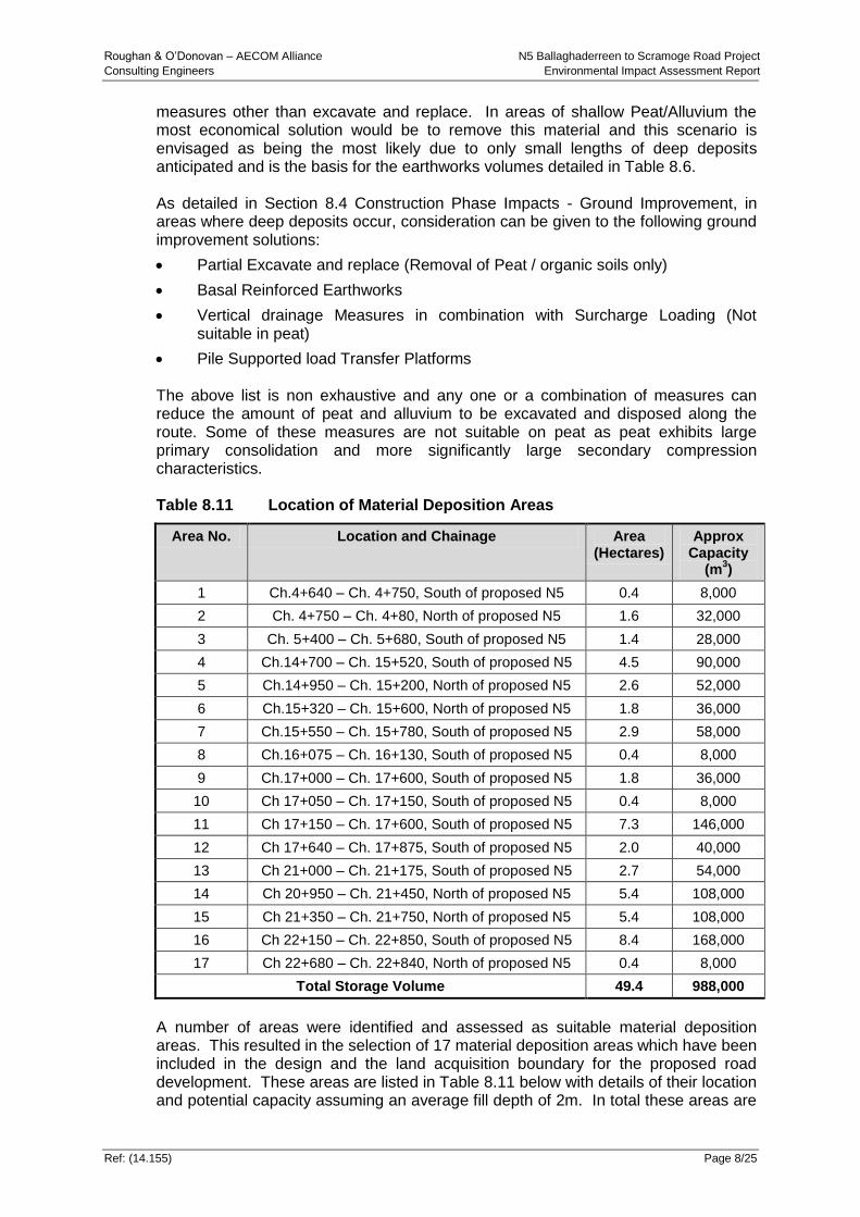
8.5.1.6 Material Deposition Areas
There will be a large amount of peat, alluvium and other unacceptable material generated from both excavate and replace operations to a suitable bearing stratum for embankment formation and from unacceptable soils derived from cuttings. The peat, alluvium, lacustrine deposits and other unacceptable materials will be stored in defined areas known as material deposition areas adjoining to or in close proximity to the project and will be contained within engineered bunds. Table 8.11 indicates the locations of material deposition areas and these are shown on the drawing series 03-600-MRA. Table 8.12 indicates quantities of earthworks disposal volumes to be utilised within the site boundary (assuming a full excavate and replace ground improvement solution) which is likely to eliminate the requirement for off-site disposal of unacceptable material. The excavation of unacceptable material above the earthworks outline will be inevitable for construction, however, the volume of material to be removed from below the earthworks outline can be reduced by the use of ground improvement
Roughan & O’Donovan – AECOM Alliance N5 Ballaghaderreen to Scramoge Road Project
Consulting Engineers Environmental Impact Assessment Report
Ref: (14.155) Page 8/25
measures other than excavate and replace. In areas of shallow Peat/Alluvium the most economical solution would be to remove this material and this scenario is envisaged as being the most likely due to only small lengths of deep deposits anticipated and is the basis for the earthworks volumes detailed in Table 8.6. As detailed in Section 8.4 Construction Phase Impacts - Ground Improvement, in areas where deep deposits occur, consideration can be given to the following ground improvement solutions:
Partial Excavate and replace (Removal of Peat / organic soils only)
Basal Reinforced Earthworks
Vertical drainage Measures in combination with Surcharge Loading (Not suitable in peat)
Pile Supported load Transfer Platforms The above list is non exhaustive and any one or a combination of measures can reduce the amount of peat and alluvium to be excavated and disposed along the route. Some of these measures are not suitable on peat as peat exhibits large primary consolidation and more significantly large secondary compression characteristics. Table 8.11 Location of Material Deposition Areas
Area No. Location and Chainage Area (Hectares)
Approx Capacity
(m3)
1 Ch.4+640 – Ch. 4+750, South of proposed N5 0.4 8,000
2 Ch. 4+750 – Ch. 4+80, North of proposed N5 1.6 32,000
3 Ch. 5+400 – Ch. 5+680, South of proposed N5 1.4 28,000
4 Ch.14+700 – Ch. 15+520, South of proposed N5 4.5 90,000
5 Ch.14+950 – Ch. 15+200, North of proposed N5 2.6 52,000
6 Ch.15+320 – Ch. 15+600, North of proposed N5 1.8 36,000
7 Ch.15+550 – Ch. 15+780, South of proposed N5 2.9 58,000
8 Ch.16+075 – Ch. 16+130, South of proposed N5 0.4 8,000
9 Ch.17+000 – Ch. 17+600, South of proposed N5 1.8 36,000
10 Ch 17+050 – Ch. 17+150, South of proposed N5 0.4 8,000
11 Ch 17+150 – Ch. 17+600, South of proposed N5 7.3 146,000
12 Ch 17+640 – Ch. 17+875, South of proposed N5 2.0 40,000
13 Ch 21+000 – Ch. 21+175, South of proposed N5 2.7 54,000
14 Ch 20+950 – Ch. 21+450, North of proposed N5 5.4 108,000
15 Ch 21+350 – Ch. 21+750, North of proposed N5 5.4 108,000
16 Ch 22+150 – Ch. 22+850, South of proposed N5 8.4 168,000
17 Ch 22+680 – Ch. 22+840, North of proposed N5 0.4 8,000
Total Storage Volume 49.4 988,000
A number of areas were identified and assessed as suitable material deposition areas. This resulted in the selection of 17 material deposition areas which have been included in the design and the land acquisition boundary for the proposed road development. These areas are listed in Table 8.11 below with details of their location and potential capacity assuming an average fill depth of 2m. In total these areas are
Roughan & O’Donovan – AECOM Alliance N5 Ballaghaderreen to Scramoge Road Project
Consulting Engineers Environmental Impact Assessment Report
Ref: (14.155) Page 8/26
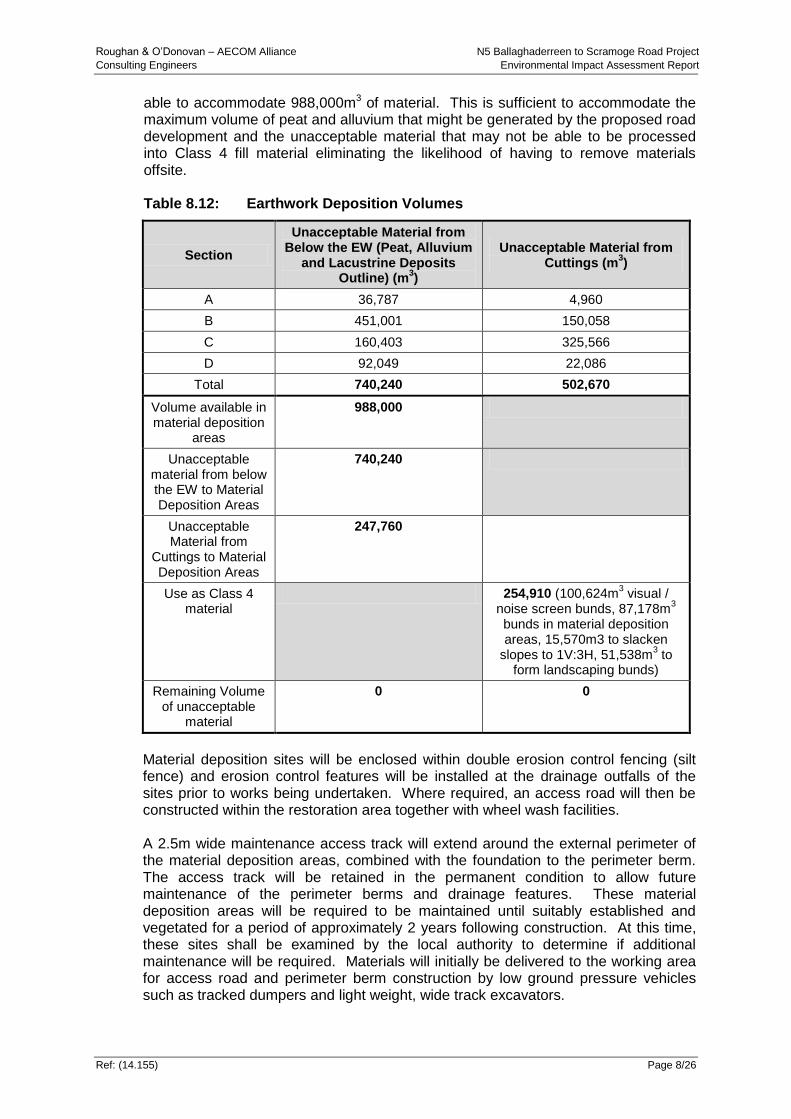
able to accommodate 988,000m3 of material. This is sufficient to accommodate the maximum volume of peat and alluvium that might be generated by the proposed road development and the unacceptable material that may not be able to be processed into Class 4 fill material eliminating the likelihood of having to remove materials offsite. Table 8.12: Earthwork Deposition Volumes
Section
Unacceptable Material from Below the EW (Peat, Alluvium
and Lacustrine Deposits Outline) (m
3)
Unacceptable Material from Cuttings (m
3)
A 36,787 4,960
B 451,001 150,058
C 160,403 325,566
D 92,049 22,086
Total 740,240 502,670
Volume available in material deposition
areas
988,000
Unacceptable material from below the EW to Material Deposition Areas
740,240
Unacceptable Material from
Cuttings to Material Deposition Areas
247,760
Use as Class 4 material
254,910 (100,624m3 visual /
noise screen bunds, 87,178m3
bunds in material deposition areas, 15,570m3 to slacken
slopes to 1V:3H, 51,538m3 to
form landscaping bunds)
Remaining Volume of unacceptable
material
0 0
Material deposition sites will be enclosed within double erosion control fencing (silt fence) and erosion control features will be installed at the drainage outfalls of the sites prior to works being undertaken. Where required, an access road will then be constructed within the restoration area together with wheel wash facilities. A 2.5m wide maintenance access track will extend around the external perimeter of the material deposition areas, combined with the foundation to the perimeter berm. The access track will be retained in the permanent condition to allow future maintenance of the perimeter berms and drainage features. These material deposition areas will be required to be maintained until suitably established and vegetated for a period of approximately 2 years following construction. At this time, these sites shall be examined by the local authority to determine if additional maintenance will be required. Materials will initially be delivered to the working area for access road and perimeter berm construction by low ground pressure vehicles such as tracked dumpers and light weight, wide track excavators.

Roughan & O’Donovan – AECOM Alliance N5 Ballaghaderreen to Scramoge Road Project
Consulting Engineers Environmental Impact Assessment Report
Ref: (14.155) Page 8/27
Material deposition areas will be constructed with a perimeter berm which will be constructed from Class 1C or Class 4 fill. The side slopes of the perimeter berm will be constructed no steeper than 1 (vertical) to 1.5 (horizontal). Where favourable ground conditions exist, the ground levels will be lowered and peat will be deposited below existing ground levels as shown on Plate 8.6 below.
Plate 8.6 Typical Detail of a Material Deposition Area
Plates 8.6 to 8.9 show previous examples of material deposition areas. These photographs demonstrate the difference in the ground following immediate deposition and then at a date two years following deposition.

Roughan & O’Donovan – AECOM Alliance N5 Ballaghaderreen to Scramoge Road Project
Consulting Engineers Environmental Impact Assessment Report
Ref: (14.155) Page 8/28
Plate 8.7 & 8.8 M7/M8 Portlaoise PPP Example – Peat Deposition Adjacent to
Kilnaseer Fen cSAC Designated Area (Note Trees in Near Horizon for Comparison)

Roughan & O’Donovan – AECOM Alliance N5 Ballaghaderreen to Scramoge Road Project
Consulting Engineers Environmental Impact Assessment Report
Ref: (14.155) Page 8/29
Plate 8.9 & 8.10 M7/M8 Portlaoise PPP Example – Peat Tip Adjacent to Kilnaseer Fen
cSAC After 2 years (Note Tree in Middle Background for Comparison)
8.5.1.7 Areas of Potential Karst Limestone
A number of potential risk karst areas have been discussed in Section 8.3 of this report. At Portaghard (Ch. 3+450m) a number of surface karst drainage features were identified at this location. A sealed drainage system for road drainage is proposed between Ch.4+000 and 4+250 to protect groundwater. A drainage layer is proposed beneath the road at Ch.4+000 to maintain the existing surface drainage patterns. At Kilvoy and Corry East (Ch. 18+400m – 19+300m) a number of swallow holes were identified within close proximity to the proposed route, with one swallow hole being located within the footprint of the proposed route. Approximate dimensions of the surface depressions are 1 – 2m in diameter. Basal reinforcement will be required in this area to ensure stability of the proposed road and to span across the karst feature located within the footprint of the proposed alignment. Soft ground or voids present at these locations will be initially excavated and backfilled with Class 6A or 6C fill to maintain the current drainage function which such depressions may serve to surrounding lands. A sealed drainage system will be required for the road drainage in this area. Also, roadway drainage ditches, swales and ponds will be located away from embankments within these specific locations to avoid increasing the flow rates and risks of soil erosion or collapse. Existing and intercepted overland and interflow from cut-off ditches within this area will be directed to the swallow hole to maintain existing recharge.

Roughan & O’Donovan – AECOM Alliance N5 Ballaghaderreen to Scramoge Road Project
Consulting Engineers Environmental Impact Assessment Report
Ref: (14.155) Page 8/30
Similar measures are anticipated from Ch. 20+350m to Ch. 20+550m in the vicinity of the observed karst feature at Ch. 20+450m. At the Carricknabraher River Bridge at Ch. 10+150m and at the Scramoge River at Ch. 52+840m, bridge foundations will require piles founded at depths in bedrock below horizons of highly weathered and voided karstified rock.
8.5.1.8 Landfills
The EPA website was consulted on the issue of landfills in the local area. None were identified along the scheme.
8.5.2 Operational Mitigation Measures
Detailed Mitigation measures are proposed for potential karst areas as already discussed in this section.
8.6 Residual Impacts The residual impacts are those that will occur after the proposed mitigation measures have taken effect and are shown in Table 8.13 and 8.14.
(a) Where there are deep cuts into bedrock the exposure of geological strata can be considered a positive residual impact in terms of the enhancement of geological heritage features. Where there are new viewpoints of the ribbed moraine features from the proposed road, this can also be considered as a positive residual impact.
(b) Where there is cut into highly fractured / weathered areas of bedrock or thick subsoils this will require ongoing monitoring and maintenance such as periodic inspections and cleaning of the spalled materials from the base of slopes.
(c) Laragan quarry is located approximately 200m north of the proposed road development at Ch. 37+200m. The owner of Laragan quarry also has property within and adjacent to the proposed road development (Ch. 36+700 – Ch. 37+950m). The construction of the proposed road at this location may reduce the amount of extraction possible if the quarry at Laragan proposes to expand its operations in this direction. The significance of this impact on soils and geology is considered to be slight.
8.6.1 Summary of Impact Assessment
An assessment of the predicted impacts, mitigation measures and residual impacts during construction are shown it Table 8.13 and in Table 8.14. There are no likely significant permanent geological impacts associated with the proposed road development. Temporary impacts related to karst can be adequately mitigated by application of appropriate engineering design controls as described in this chapter.

Roughan & O’Donovan – AECOM Alliance N5 Ballaghaderreen to Scramoge Road Project Consulting Engineers Environmental Impact Assessment Report
Ref: (14.155) Page 8/31
Table 8.13 Predicted Geological Impacts during Construction Phase
Feature Impact Assessment Construction Mitigation Measure Residual Impact Name Importance Chainage Magnitude of
Impact Criteria for Impact
Assessment Significance
of Impact
Potential Karst in Limestone in Regionally Important Aquifer (Rkc)
Medium 3+450m
18+450 – 19+300 20+350 – 20+550
Small Adverse Required to incorporate karst protection measures into road
Moderate to Significant
Good construction practices to be put in place to ensure that the groundwater is not contaminated during the construction of the road, ensure that karstified rock is not exposed during excavations, ensure that there is no change in drainage patterns
Slight
Peat / Unacceptable Material Disposal
Medium Peat has been identified at numerous locations along the route of the road as indicated in Section 8.3.
Moderate Adverse or Small Adverse
A significant amount of peat or soft material to be removed from beneath the road.
Sufficient locations along the project have been identified to facilitate deposition of this material.
Moderate Partial excavate and replace
Deposition of peat within the CPO boundary within material deposition areas
Basal reinforced earthworks
Pile supported load transfer platforms
Slight
Soils and Rock Slopes in Areas of Cut
Low As detailed in Tables 8.8 and 8.9.
Small Adverse Instability in cut slopes due to groundwater seepages, layers of weak material in soil and rock and discontinuities on slope face.
Slight Monitoring of and maintenance of slopes such as periodic inspections and cleaning of spalled materials from the base of slopes.
Imperceptible

Roughan & O’Donovan – AECOM Alliance N5 Ballaghaderreen to Scramoge Road Project Consulting Engineers Environmental Impact Assessment Report
Ref: (14.155) Page 8/32
Table 8.14 Predicted Geological Impacts During Operational Phase
Feature Impact Assessment Construction Duration of Impact
Mitigation Measure
Residual Impact Name Importance Chainage Magnitude
of Impact Criteria for Impact
Assessment Significance
of Impact
Potential Karst in Limestone in Regionally Important Aquifer (Rkc)
Medium 3+450m
18+450 – 19+300 20+350 – 20+550
Small Adverse
Potential Karst area under road
Moderate / Slight
Permanent Incorporation of drainage protection measures. Basal reinforcement
Slight
Peat / Unacceptable Material Disposal
Medium Deposition of unacceptable material within material deposition areas within the CPO boundary (Table 8.11)
Moderate Adverse
Deposited peat liable to ongoing long term settlement
Moderate / Slight
Permanent Landscaping use and in engineered bunds (soft clay - Class 4 material) of material deposition areas
Slight
Exposure of Rock in Deep Cuttings, new viewpoints of ribbed moraine features
Medium Ch. 35+100 – 36+470m and 36+900 – 37+650m
Moderate Beneficial
Allows rock strata to be exposed, enhances visual and landscape impact
Moderate Permanent Moderate, Positive
Reduction in future expansion possibilities of Laragan Quarry
Medium Ch. 36+700 – 37+950m
Small Adverse
Reduction in future expansion possibilities of Laragan Quarry
Moderate / Slight
Permanent Slight