churchill - ge oil and gas · churchill. i warning the beam balanced pumping units are designed to...
TRANSCRIPT
P.O. BOX 849, LUFKIN, TEXAS 75902-0849PHONE: 936/634-2211
FAX: 936-633-3563
INSTALLATION MANUAL B-05WARNING: Failure to use this manual for guidance could result in injury to
personnel and/or damage to equipment.
MANUFACTURED BY
BEAM BALANCED PUMPING UNITS
CHURCHILL

i
WARNING
The Beam Balanced Pumping Units are designed to give many years ofdependable service. Like all machines with moving parts, there are “potential”hazards associated with its use. These hazards can be reduced if the machineis properly installed, operated and maintained. All personnel who install, operateor maintain the unit must read this manual and must be trained to use the machinein an appropriate and safe manner. Should any questions arise concerningthe maintenance or operation of the machine, contact LUFKIN Industries, Inc. at1-936-634-2211.
Do Not allow personnel to standunder moving loads or parts.
Set brake, and chain walking beamduring installation and maintenanceto prevent movement of beamweights and cranks.
Keep clear of beam weight andcrank swing area and other partsthat may start moving.
Do Not operate pumping units with-out proper guards in place.
Do Not service well without removingthe horsehead.
Properly install the horsehead latch bolt.
Keep pumping units at least 10 feet away from all overhead wires.
Lockout/ tagout ALL energy sources.
All electrical work must be per-formed by a qualified electrician.
POTENTIAL HAZARD EFFECT PREVENTION
ELECTRICAL CONTACT
MOVING LOADS ORPARTS
Can causesevere injury or death.
Will cause severe injury or death.
ii
FOREWORD
The Beam Balanced pumping unit is a Class I lever system having beamcounterbalance. The Beam Balanced unit may be operated in either direction of rotation.The four bar lever system converts rotational motion at the crank to reciprocating motionat the horsehead and in turn to the down hole pump.
Beam Balanced pumping units have been designed to rigid LUFKIN standards andexceed API (American Petroleum Institure) standard requirements for pumping unitdesign. In addition, all individual components of the unit and the unit as a wholerepresent the very best engineering design, production facilities, quality and fieldexperience that almost a century of LUFKIN INDUSTRIES’ experience can bring to you.Your Beam Balanced unit will give many years of dependable service when properlyinstalled, maintained and operated within its load and torque ratings.
To avoid confusion, some of the more common terms used concerning pumping units are defined as follows:
Front: is the well head (horsehead) end. Rear: is the prime mover end.Left & Right: are determined by standing at the rear of the pumping unit and facing the well head.Crank Sweep or Crank Swing: is the circular area centered about the crankshaft where the cranks will rotate when in motion.
NOTE: Some of the photographs and illustrations used in this manual are representative and may not look exactly like the parts with which you are working.
iii
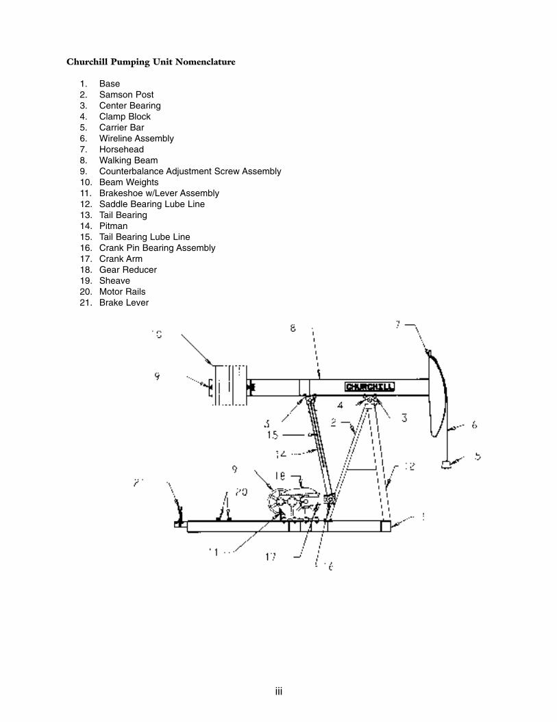
Churchill Pumping Unit Nomenclature
1. Base2. Samson Post3. Center Bearing4. Clamp Block5. Carrier Bar6. Wireline Assembly7. Horsehead8. Walking Beam9. Counterbalance Adjustment Screw Assembly10. Beam Weights11. Brakeshoe w/Lever Assembly12. Saddle Bearing Lube Line13. Tail Bearing14. Pitman15. Tail Bearing Lube Line16. Crank Pin Bearing Assembly17. Crank Arm18. Gear Reducer19. Sheave20. Motor Rails21. Brake Lever
iv
i. Warnings
ii. Foreword
iii. Nomenclature
1. SAFETY
1.1 Hazard Identification1.2 Some Potential Hazards1.3 Commonly Used Safety Procedures
1.3.1 Installing the Walking Beam and Horsehead
1.4 Guarding of Units
1.4.1 Crank Guards1.4.2 Horsehead Guards1.4.3 Belt Guards1.4.4 Prime Mover Guards
1.5 Proper Clothing and Tools1.6 Training
2. INSTALLATION EQUIPMENT SIZING CHARTS
3. FASTENERS
3.1 “Metal-to-Metal” Grip3.2 “Elastic” Grip
4. FOUNDATION
4.1 General4.2 Types of Foundations4.3 Well Head Clearance4.4 Alignment Marks
5. UNIT INSTALLATION
5.1 Base Installation5.2 Reducer Information5.3 Brake System Adjustment5.4 Samson Post Installation5.5 Prime Mover Installation5.6 “V-Belts” Installation and Alignment5.7 Belt Cover Installation5.8 Reducer Lubrication5.9 Beam Weight Installation
v
5.10 Horsehead/Wireline Installation5.11 Walking Beam Installation5.12 Equalizer Bearing Lubrication & Hose Installation5.13 Center Bearing Lubrication & Hose Installation5.14 Horsehead Alignment5.15 Unit Alignment5.16 Bearing Assembly Lubrication5.17 Crank Guard Installation5.18 Attaching the Well Load
6. PRE-OPERATION
6.1 Direction of Rotation6.2 First Crank Revolution
7. COUNTERBALANCE ADJUSTMENT
7.1 Determining the Required Counterbalance7.2 Beam Weight Adjustment
8. STROKE CHANGE
8.1 Preparation8.2 Changing Stroke Length8.3 Moving Equalizer/Pitman on Walking Beam8.4 Crank Pin Removal8.5 Crank Pin Installation8.6 Putting the Unit into Operation
9. WELL SERVICING
9.1 Preparation9.2 Horsehead Removal9.3 Horsehead Installation9.4 Putting the Unit into Operation
10. PREVENTIVE MAINTENANCE
11. SCHEDULED MAINTENANCE
11.1 MonthlyReducer
11.1.1 Reducer11.1.2 Structural Bearings

vi
11.2 Quarterly
11.2.1 Belts and Sheaves11.2.2 Brake11.2.3 Brake Sheave Drum11.2.4 Brake Rods11.2.5 Crank Phase Marks
11.3 Semi-Annually
11.3.1 Reducer11.3.2 Structural Bearings11.3.3 Wireline11.3.4 Bolts11.3.5 Safety Signs
12. LUBRICANT SPECIFICATIONS
12.1 Reducer12.2 Reducer Oil Capacity12.3 Structural Bearings 12.4 Wireline
13. LUFKIN SERVICE
13.1 Personnel13.2 Repair and Replacement Parts
14. SAFETY SIGN REPLACEMENT
1
INSTALLATION MANUAL
BEAM BALANCED PUMPING UNITS
1. SAFETY
Before proceeding with the installation, operation or maintenance of a pumping unit, familiarize yourself with Federal, State and Local laws, your company’s safety regulationsand the safety section of this manual. For your protection and to prevent equipment damage, please heed the product safety signs attached to the pumping unit.
1.1 HAZARD IDENTIFICATION
DANGER: Indicates an imminently hazardous situation which, if not avoided, willresult in serious injury or death.
WARNING: Indicates a potentially hazardous situation which, if not avoided, could resultin serious injury or death.
CAUTION: Indicates a potentially hazardous situation which, if not avoided, could result in minor or moderate injury or damage to the unit.
1.2 SOME POTENTIAL HAZARDS
Failure to heed the following WARNINGS could result in severe bodily injury or death to personnel:
• Pumping units have large and heavy moving parts. Even a temporarily stationary pumping unit has components which can start moving from the effectof gravity. Times of particular danger are during unit installation, stroke change, counterbalance change, general unit maintenance, well servicing and while taking dynamometer card readings.
Whenever performing maintenance on, or working around the pumping unit,always lockout/tagout all energy sources and secure the beam and cranks againstrotation. All personnel must stay alert and keep clear of the crank swing area,counterweight area, horsehead area and other potential moving parts.
• Never stand under the walking beam or horsehead during their installation orremoval. Double check the horsehead for proper installation on the walking beam, including the installation of the latch bolt before rotating the unit.
Remove the horsehead before servicing the well, remembering to first removelatch bolt.
2
• Do not stand under moving parts or loads being lifted. Always attach guide ropes to parts to aid in initial alignment of parts or assemblies.
• All electrical work must be performed by a qualified electrician. Regularly inspectand maintain electric motors, automatic timers or any other electrical device.
• Be aware of power line locations, keeping unit and service equipment at least ten feet away.
• Do not assume a stationary unit is not operational. Automatic timers can start units in motion without warning.
• LUFKIN does not recommend installing nor performing maintenance on pumpingunits during thunderstorms. Exercise extreme caution during icy conditions andother inclement weather.
1.3 COMMONLY USED SAFETY PROCEDURES FOR SECURING CRANKS
DANGER: Do not enter the beam weight, horsehead or crank swing area to chainthe beam or engage the brake.
Always install the unit and perform maintenance with the cranks at the 6 o’clock positionwhen possible. If the cranks are straight down, no rotation will start if the carrier bar is notattached to the polished rod, or if the polished rod has been securely clamped at the stuffing box to hold the well load and all energy sources have been locked out/tagged out.
It is essential to prevent rotation of the cranks stopped in any position. Never use the brake alone as a safety stop. Always use as many other methods as possible for back upsalong with your company’s lockout/tagout procedure.
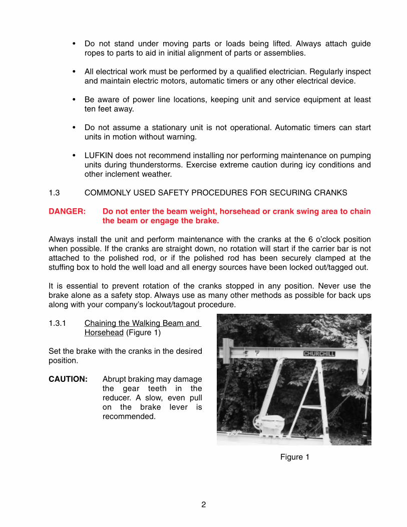
1.3.1 Chaining the Walking Beam and Horsehead (Figure 1)
Set the brake with the cranks in the desired position.
CAUTION: Abrupt braking may damagethe gear teeth in thereducer. A slow, even pullon the brake lever isrecommended.
Figure 1
3
Attach a sturdy (never less than 3/8 Grade 8 alloy) chain from the bottom of the horseheadto the base and a second chain from the rear of the walking beam to the base. Use a safecome-a-long or ratchet-boomer to tighten chains.
WARNING: Faulty chains and slings could fail and cause severe bodily injury or death.
1.4 GUARDING OF UNITS
DANGER: Contact with large moving parts will cause severe injury or death. Do not operate pumping units without proper guards in place. The purpose of guards is to provide a safety barrier between the moving parts of the pumping unit and people who are familiar with theoperation of pumping units. They also provide a barrier between themoving parts and animals. When pumping units are operated where they are accessible to the general public, it may be necessary to placethe pumping unit with guards in an enclosed area with a lockedentrance. The enclosure must prevent entry of unauthorized persons.Federal, State and local regulations may require specific types of guarding, dependent upon the location of your unit; therefore, the typeof guarding needed is known only by the user who must choose theproper guarding. It is essential that the user of the pumping unit comply with all applicable safety requirements. For additional information on guarding of pumping units, refer to API RP11ER.
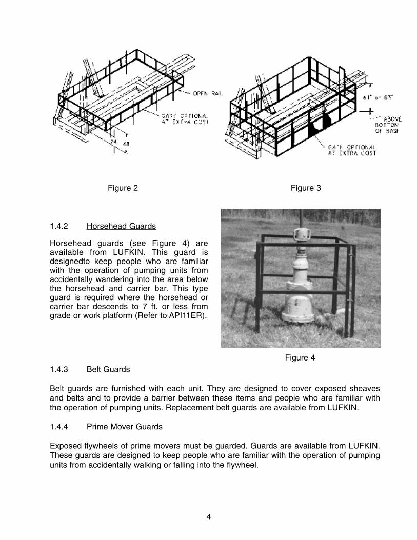
1.4.1 Crank Guards
Crank guards are available from LUFKIN (see Figures 2 and 3). Under normal operating circumstances, the 48'' open rail guards would be considered minimum guarding for peoplewho are familiar with pumping units and who are accustomed to working around them.Basically, this type guard simply keeps workers from accidentally wandering or falling into the beam weight or crank areas. The 61'' and 83'' wire mesh guards would normally beconsidered adequate guarding for people familiar with the operation of pumping units andaccustomed to working around them, as well as smaller animals who might be able to movethrough the guards described above. Custom built guards are available to meet customer requirements.
4
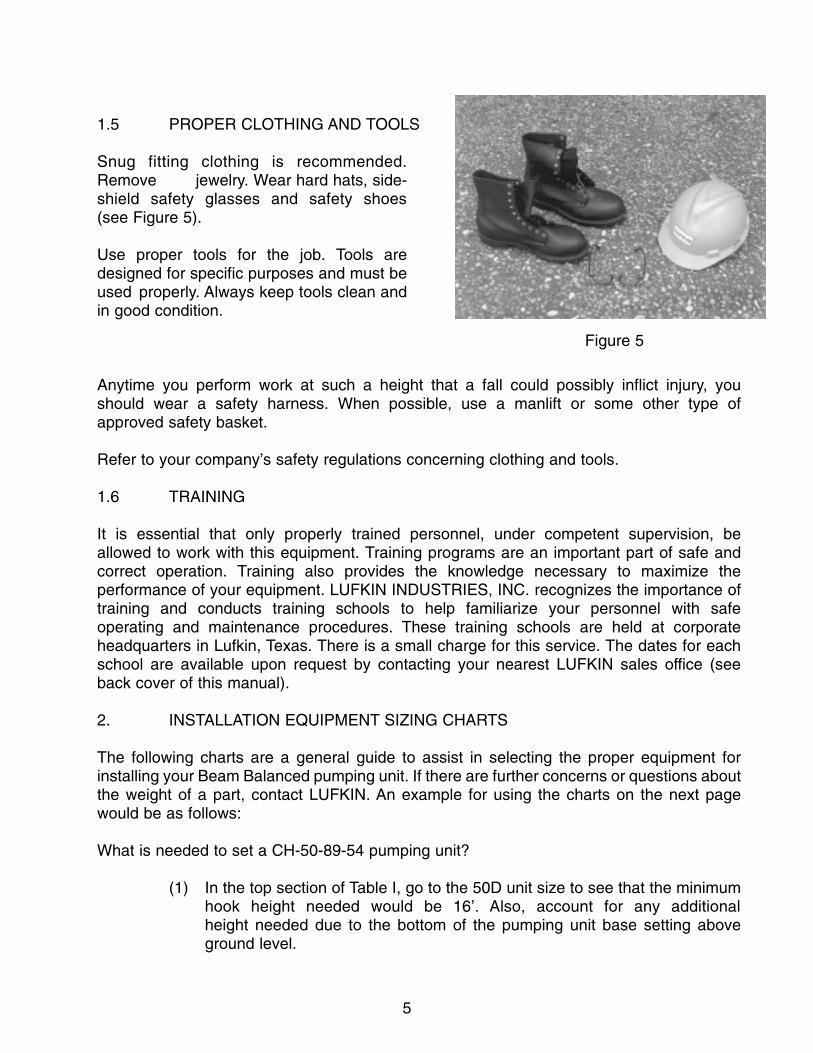
1.4.2 Horsehead Guards
1.4.3 Belt Guards
Belt guards are furnished with each unit. They are designed to cover exposed sheaves and belts and to provide a barrier between these items and people who are familiar with the operation of pumping units. Replacement belt guards are available from LUFKIN.
1.4.4 Prime Mover Guards
Exposed flywheels of prime movers must be guarded. Guards are available from LUFKIN.These guards are designed to keep people who are familiar with the operation of pumpingunits from accidentally walking or falling into the flywheel.
Figure 2 Figure 3
Figure 4
Horsehead guards (see Figure 4) areavailable from LUFKIN. This guard isdesignedto keep people who are familiarwith the operation of pumping units fromaccidentally wandering into the area belowthe horsehead and carrier bar. This typeguard is required where the horsehead orcarrier bar descends to 7 ft. or less fromgrade or work platform (Refer to API11ER).
5
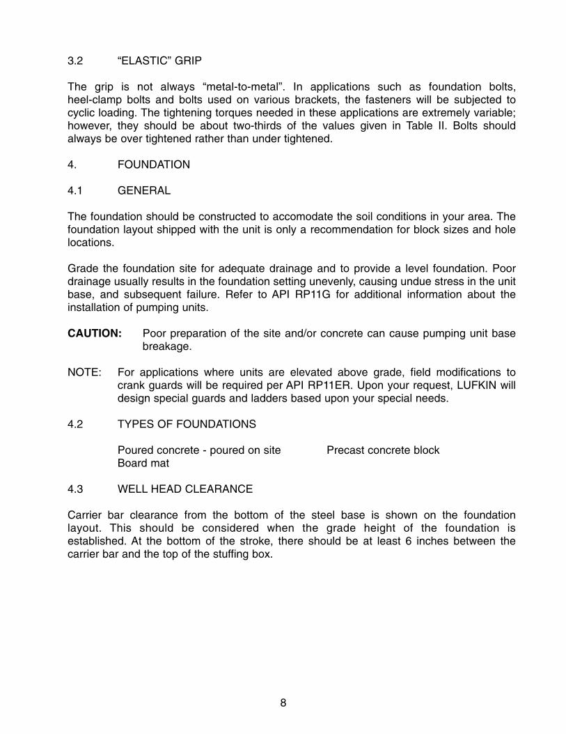
1.5 PROPER CLOTHING AND TOOLS
Snug fitting clothing is recommended.Remove jewelry. Wear hard hats, side-shield safety glasses and safety shoes (see Figure 5).
Use proper tools for the job. Tools aredesigned for specific purposes and must beused properly. Always keep tools clean andin good condition.
Anytime you perform work at such a height that a fall could possibly inflict injury, you should wear a safety harness. When possible, use a manlift or some other type of approved safety basket.
Refer to your company’s safety regulations concerning clothing and tools.
1.6 TRAINING
It is essential that only properly trained personnel, under competent supervision, be allowed to work with this equipment. Training programs are an important part of safe and correct operation. Training also provides the knowledge necessary to maximize the performance of your equipment. LUFKIN INDUSTRIES, INC. recognizes the importance oftraining and conducts training schools to help familiarize your personnel with safe operating and maintenance procedures. These training schools are held at corporate headquarters in Lufkin, Texas. There is a small charge for this service. The dates for eachschool are available upon request by contacting your nearest LUFKIN sales office (see back cover of this manual).
2. INSTALLATION EQUIPMENT SIZING CHARTS
The following charts are a general guide to assist in selecting the proper equipment forinstalling your Beam Balanced pumping unit. If there are further concerns or questions aboutthe weight of a part, contact LUFKIN. An example for using the charts on the next pagewould be as follows:
What is needed to set a CH-50-89-54 pumping unit?
(1) In the top section of Table I, go to the 50D unit size to see that the minimum hook height needed would be 16’. Also, account for any additional height needed due to the bottom of the pumping unit base setting aboveground level.
Figure 5

6
(2) To determine the heaviest lift required, refer to the third column in the top section of Table 1.
(3) If you are moving a reducer with cranks attached, refer to the lower sectionof Table 1, third column.
Table I
Approximate Weight and Hook Data for Installation Purposes
UNIT +MINIMUM HOOK SIZE HEIGHT
6.4D* 11’ - 6” 660 775 ---10D* 12’ - 6” 780 900 ---13D* 13’ - 6” 933 1,050 ---16D* 15’ - 6” 1,450 1,695 1,74025D* 16’ - 0” 2,000 2,335 2,47040D* 16’ - 0” 2,300 2,785 2,95050D* 16’ - 0” 2,325 2,800 2,97557D* 16’ - 6” 3,385 4,035 4,43580D* 16’ - 6” 3,450 4,105 4,495114D 16’ - 6” 4,250 --- 5,725
+ Height of unit plus standard flat bed trailer* Units are shipped complete with walking beam and
horsehead assembled
WEIGHT W/ SHEAVE WEIGHT W/ CRANKS,REDUCER SIZE & OIL (LBS) SHEAVE & OIL
6.4D 208 23010D 256 30013D 410 44016D 425 48025D 460 56040D 905 1,09550D 920 1,11057D 1,805 1,99080D 1,875 2,060
114D 2,465 2,730
UNIT WEIGHT TABLE(INCLUDES BASE, GEARREDUCER AND CRANKS
T-BASE PORT-BASE PORT-BASEELEC. (LBS.) ELEC. (LBS.) GAS (LBS.)

7
3. FASTENERS
3.1 “METAL-TO-METAL” GRIP
Bolting is a vital part of an oil field pumping unit. The surfaces under the bolt head, nut andthe contacting surfaces must be flat, clean and free of burrs so the bolted members join in“metal-to-metal” contact. Bolts, which are properly tightened during unit installation andretightened about a week later, will retain their grip under normal operating conditions.Improperly tightened bolts will break in fatigue and may cause serious failures and injury topersonnel. Table II gives recommended tightening torques.
Since high-capacity torque wrenches are not commonly available, the larger size bolts areusually hammered tight. Use a box-end wrench with a striking face and tighten the bolts untilthe hammer blows feel solid. Bolts will fail in fatigue from inadequate tightening rather than from being pulled in two from excessive tightening torque.
WARNING: Proper eye protection must be worn; flying metal could cause damage to the eyes.
TABLE II
Proper Tightening Torques
Nuts and Cap Screws with “Metal-to-Metal” Grip
Grade 2 Grade 5
3/8 - 16 NC 19 to 21 ft.lb. 30 to 32 ft.lb.1/2 - 13 NC 47 to 51 ft.lb. 71 to 79 ft.lb.5/8 - 11 NC 92 to 102 ft.lb. 143 to 157 ft.lb.3/4 - 10 NC 164 to 180 ft.lb. 253 to 279 ft.lb.7/8 - 9 NC 159 to 176 ft.lb. 409 to 451 ft.lb.
1 - 8 NC 238 to 262 ft.lb. 612 to 676 ft.lb.1 1/8 - 7 NC 336 to 372 ft.lb. 866 to 958 ft.lb.1 1/4 - 7 NC 475 to 525 ft.lb. 1064 to 1176 ft.lb.1 1/2 - 6 NC 826 to 912 ft.lb. 1849 to 2049 ft.lb.
8
3.2 “ELASTIC” GRIP
The grip is not always “metal-to-metal”. In applications such as foundation bolts, heel-clamp bolts and bolts used on various brackets, the fasteners will be subjected to cyclic loading. The tightening torques needed in these applications are extremely variable;however, they should be about two-thirds of the values given in Table II. Bolts should always be over tightened rather than under tightened.
4. FOUNDATION
4.1 GENERAL
The foundation should be constructed to accomodate the soil conditions in your area. Thefoundation layout shipped with the unit is only a recommendation for block sizes and holelocations.
Grade the foundation site for adequate drainage and to provide a level foundation. Poordrainage usually results in the foundation setting unevenly, causing undue stress in the unitbase, and subsequent failure. Refer to API RP11G for additional information about theinstallation of pumping units.
CAUTION: Poor preparation of the site and/or concrete can cause pumping unit basebreakage.
NOTE: For applications where units are elevated above grade, field modifications tocrank guards will be required per API RP11ER. Upon your request, LUFKIN willdesign special guards and ladders based upon your special needs.
4.2 TYPES OF FOUNDATIONS
Poured concrete - poured on site Precast concrete blockBoard mat
4.3 WELL HEAD CLEARANCE
Carrier bar clearance from the bottom of the steel base is shown on the foundation layout. This should be considered when the grade height of the foundation is established. At the bottom of the stroke, there should be at least 6 inches between thecarrier bar and the top of the stuffing box.
9
The polished rod should be vertical to minimize stuffing box wear and to aid in the alignment of the unit.
4.4 ALIGNMENT MARKS (Figure 6)
5. UNIT INSTALLATION
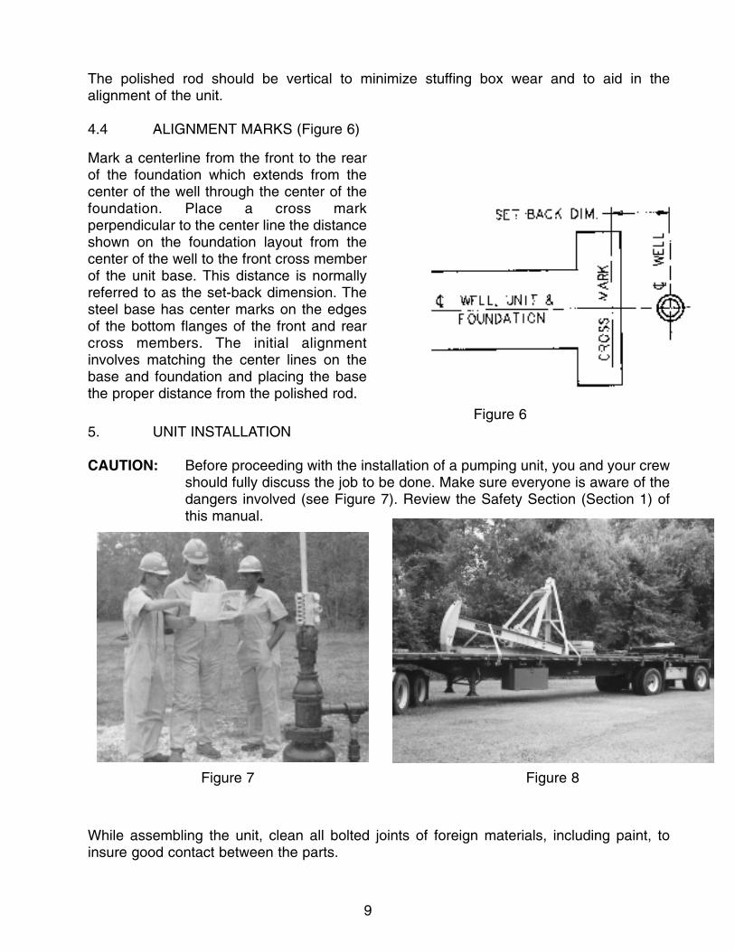
CAUTION: Before proceeding with the installation of a pumping unit, you and your crewshould fully discuss the job to be done. Make sure everyone is aware of thedangers involved (see Figure 7). Review the Safety Section (Section 1) of this manual.
While assembling the unit, clean all bolted joints of foreign materials, including paint, toinsure good contact between the parts.
Mark a centerline from the front to the rearof the foundation which extends from thecenter of the well through the center of thefoundation. Place a cross markperpendicular to the center line the distanceshown on the foundation layout from thecenter of the well to the front cross memberof the unit base. This distance is normallyreferred to as the set-back dimension. Thesteel base has center marks on the edgesof the bottom flanges of the front and rearcross members. The initial alignmentinvolves matching the center lines on thebase and foundation and placing the basethe proper distance from the polished rod.
Figure 6
Figure 7 Figure 8

10
The Beam Balanced unit is shipped partially assembled to reduce the installation timerequired (See Figure 8). Some units are shipped completely assembled where the overallheight of the load does not exceed highway limits.
The following picture and written description of the installation of a Beam Balanced pumpingunit gives the general sequence to be followed, along with precautions and alignment checks.
5.1 BASE INSTALLATION (Figure 9)
WARNING: Do not stand under the loadwhile installing base.
If you have a two piece base (unit base and prime mover base), the prime mover base willbe positioned next. Remove the bolts from the joint plates. Join the bases together, tightening the bolts according to the recommendations given in Section 3. Locate and install foundation hold-down clamps and bolts. Snug tighten. Final tightening of the foundation bolts will be done after unit alignment (procedure 5.11).
5.2 REDUCER INFORMATION
Reducers are shipped installed on the base with the brake shoe engaged against thesheave. Also, all crank pins are shipped mounted in the cranks. Should any of the crank pinsneed to be replaced, refer to Procedures 8.4 and 8.5
5.3 BRAKE SYSTEM ADJUSTMENT FOR CHURCHILL MODELS 16 THROUGH 80
WARNING: The brake is not intended as a safety stop but is intended for operational use only. When maintenance is to be conducted on or around the pumping unit,the cranks and beam weights must be securely fixed in a stationary position.(Refer to Section 1.3 of this manual.)
Lift the unit in a level position and place onthe foundation. Align the center line markson the bottom flanges of the front and rearcrossmembers with the center line mark onthe foundation. Position the frontcrossmember of the base the correctdistance from the center of the well head.
Figure 9

11
These units are shipped from the factory with the brake pre-adjusted. Over a period of time,however, the brake will need to be adjusted and the following procedure should be used:
Step 1. Loosen the yoke lock nut on the brake rod (Figure 10).
Step 2. Remove the cotter pin and clevis pin that holds the yoke to the brake lever.
Step 3. Turn the yoke so as to shorten the brake rod thereby closing the gap between thebrake shoe and the sheave (Figure 11).
Step 4. Replace clevis pin and cotter pin. Retighten yoke lock nut on the brake rod.
Clean the surfaces between the unit base and footplates of the Samson post.
Figure 10 Figure 11
NOTE: The brake shoe should not beadjusted so tight that the shoe drags on thesheave during operation, nor so loose thatthe brake lever is out of operational range ofstopping the unit should an emergency arise.A clearance of .020” to .030” between thebrake pad and sheave is recommended.
5.4 SAMSON POST INSTALLATION
Most units will ship with the Samson postinstalled. Some units require Samson postinstallation on location as follows:
WARNING: Do not stand under any part ofthe load while installing Samson post.
Figure 12
12
Lift the post assembly with a sling attached near the top of the assembly. This will hang thepost in a near level position for easy attachment to the base, as shown in Figure 12.
Attach the front and rear post members to the base by installing the bolts from the bottomso the nuts will be on the topside. Tighten bolts according to recommendations in Section 3.
5.5 PRIME MOVER INSTALLATION
WARNING: Do not stand under any part of the load while installing the prime mover; do notplace fingers and hands between the prime mover and the slide rails.
Place the slide rails near the reducer so the belts can be easily installed after positioningthe prime mover. Space the slide rails to match the mounting holes of the prime mover.Install and space the mounting bolts in the T-slots on the slide rails to match the mountingholes of the prime mover. Slowly lower the prime mover onto the mounting bolts. To preventinjury to fingers and hands, use pliers or other tools to position the bolts. Install the nuts butdo not tighten until the belt alignment is completed.
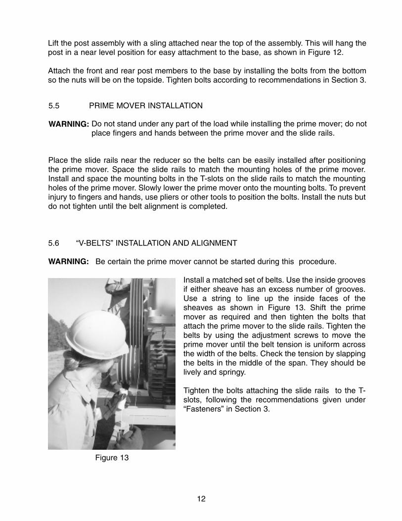
5.6 “V-BELTS” INSTALLATION AND ALIGNMENT
WARNING: Be certain the prime mover cannot be started during this procedure.
Install a matched set of belts. Use the inside groovesif either sheave has an excess number of grooves.Use a string to line up the inside faces of thesheaves as shown in Figure 13. Shift the primemover as required and then tighten the bolts thatattach the prime mover to the slide rails. Tighten thebelts by using the adjustment screws to move theprime mover until the belt tension is uniform acrossthe width of the belts. Check the tension by slappingthe belts in the middle of the span. They should belively and springy.
Tighten the bolts attaching the slide rails to the T-slots, following the recommendations given under“Fasteners” in Section 3.
Figure 13
13
5.9 BEAM WEIGHT INSTALLATION
WARNING: This machinery is made up of heavy parts that can rotate unexpectedly.Extreme care must be exercised when working around the sweep of the cranks and walking beam.
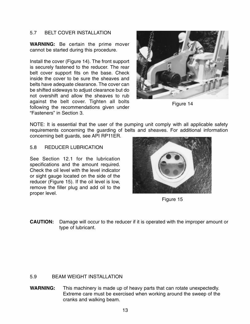
5.7 BELT COVER INSTALLATION
WARNING: Be certain the prime movercannot be started during this procedure.
Install the cover (Figure 14). The front supportis securely fastened to the reducer. The rearbelt cover support fits on the base. Checkinside the cover to be sure the sheaves andbelts have adequate clearance. The cover canbe shifted sideways to adjust clearance but donot overshift and allow the sheaves to rubagainst the belt cover. Tighten all boltsfollowing the recommendations given under“Fasteners” in Section 3.
NOTE: It is essential that the user of the pumping unit comply with all applicable safetyrequirements concerning the guarding of belts and sheaves. For additional informationconcerning belt guards, see API RP11ER.
5.8 REDUCER LUBRICATION
See Section 12.1 for the lubricationspecifications and the amount required.Check the oil level with the level indicatoror sight gauge located on the side of thereducer (Figure 15). If the oil level is low,remove the filler plug and add oil to theproper level.
CAUTION: Damage will occur to the reducer if it is operated with the improper amount ortype of lubricant.
Figure 15
Figure 14
14
WARNING: Improperly tightened weight bolts can allow the weights to move on thewalking beam. Impact movement of the weights could break the weight andbolts and damage the unit or cause serious injury or death.
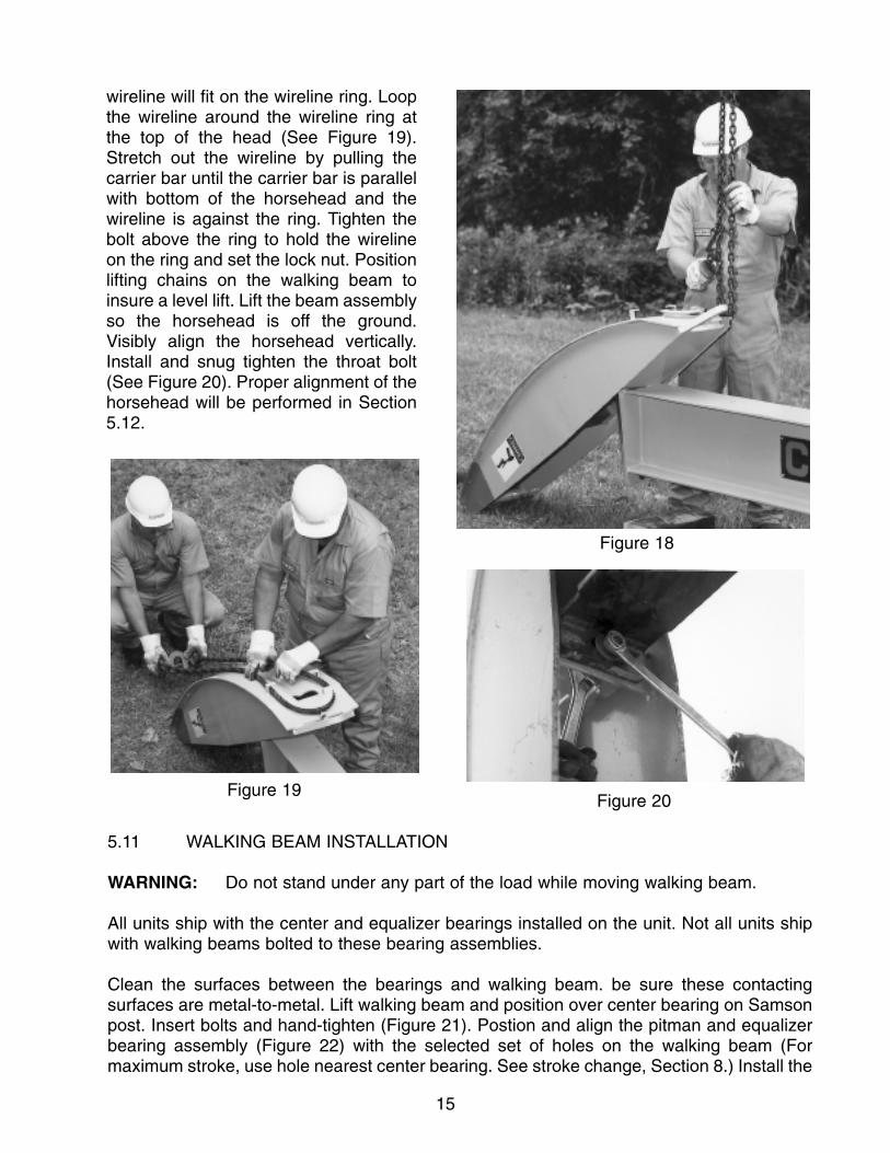
5.10 HORSEHEAD/WIRELINE INSTALLATION
Lift the horsehead over the front of the walking beam and place the radius plate of thehorsehead behind the head plate of the walking beam. The radius plate should rest on thebeam and against the head plate (See Figure 18). Adjust the bolt on top of the head so the
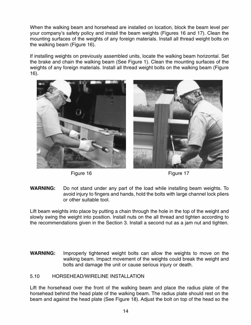
When the walking beam and horsehead are installed on location, block the beam level peryour company’s safety policy and install the beam weights (Figures 16 and 17). Clean themounting surfaces of the weights of any foreign materials. Install all thread weight bolts onthe walking beam (Figure 16).
If installing weights on previously assembled units, locate the walking beam horizontal. Setthe brake and chain the walking beam (See Figure 1). Clean the mounting surfaces of theweights of any foreign materials. Install all thread weight bolts on the walking beam (Figure16).
WARNING: Do not stand under any part of the load while installing beam weights. Toavoid injury to fingers and hands, hold the bolts with large channel lock pliersor other suitable tool.
Lift beam weights into place by putting a chain through the hole in the top of the weight andslowly swing the weight into position. Install nuts on the all thread and tighten according tothe recommendations given in the Section 3. Install a second nut as a jam nut and tighten.
Figure 16 Figure 17
15
5.11 WALKING BEAM INSTALLATION
WARNING: Do not stand under any part of the load while moving walking beam.
All units ship with the center and equalizer bearings installed on the unit. Not all units shipwith walking beams bolted to these bearing assemblies.
Clean the surfaces between the bearings and walking beam. be sure these contactingsurfaces are metal-to-metal. Lift walking beam and position over center bearing on Samsonpost. Insert bolts and hand-tighten (Figure 21). Postion and align the pitman and equalizerbearing assembly (Figure 22) with the selected set of holes on the walking beam (Formaximum stroke, use hole nearest center bearing. See stroke change, Section 8.) Install the
Figure 19Figure 20
Figure 18
wireline will fit on the wireline ring. Loopthe wireline around the wireline ring atthe top of the head (See Figure 19).Stretch out the wireline by pulling thecarrier bar until the carrier bar is parallelwith bottom of the horsehead and thewireline is against the ring. Tighten thebolt above the ring to hold the wirelineon the ring and set the lock nut. Positionlifting chains on the walking beam toinsure a level lift. Lift the beam assemblyso the horsehead is off the ground.Visibly align the horsehead vertically.Install and snug tighten the throat bolt(See Figure 20). Proper alignment of thehorsehead will be performed in Section5.12.

16
Figure 23
5.13 CENTER BEARING LUBRICATION & HOSE INSTALLATION
On units using ground lubrication, attachthe lubrication hose to the lubrication line,which is located on the leg of the Samsonpost, and fill the hose/line assembly with agrease recommended in Section 12.3.Attach the hose to the center bearing(Figure 24). Check the center bearinglubrication per Section 5.16.
5.12 EQUALIZER BEARING LUBRICATION AND HOSE INSTALLATION
On units using ground lubrication, attach the lubrication hose to the lubrication line on thepitman and fill with grease as specified in Section 12.3. Then attach the hose to theequalizer bearing housing (Figure 23). Only one line is needed for equalizer bearinglubrication. Check the equalizer bearing lubrication per Section 5.16.
Figure 21 Figure 22
bolts and hand-tighten. Measure the distance between the end of the center bearing shaftand the end of the equalizer bearing shaft on both sides. (For proper alignment, thesedistances should be the same.)
After obtaining the alignment, tighten the bolts between the center bearing and the walkingbeam and the equalizer bearing and walking beam per Section 3. Secure the walking beamand cranks from rotation. See Section 1.3.
CAUTION: Improper tightening of the center bearing to walking beam bolts can resultin broken bolts which in turn will cause severe damage to the pumping unit.

17Figure 26
5.14 HORSEHEAD ALIGNMENT
With the walking beam in a horizontal position, use a level or a plumb bob to check thevertical alignment of the horsehead. The horsehead may be adjusted by using a pry bar ormallet to move the horsehead to right or left as required to properly align (Figure 25). Makesure throat bolt is properly tightened.
NOTE: It is essential that the user of the pumping unit comply with all applicable safetyrequirements concerning the guarding of horseheads. Refer to API RP11ER. Guards areavailable from LUFKIN.
5.15 UNIT ALIGNMENT (Figure 26)
Using a rope, hold the carrier bar away from the polished rod. Do not stand under thehorsehead. Lower a plumb bob from the center of the top of the horsehead down beside thepolished rod. Alignment is achieved when the distance from the string to the center of thepolished rod is the same as the distance between thestring and where the center of the wireline will travel whenconnected to the well load. An alternate method can beused after complete unit assembly and before starting theunit. After applying the well load to the unit, use a level tocheck the vertical alignment of the polished rod in variousstroke positions and in two planes at right angles to eachother. Move the entire pumping unit on its foundation ifadjustment is required.
After establishing the final alignment of the unit to thewell, be sure all foundation hold-down clamps areinstalled. Tighten the foundation bolts and check all otherbolts to be sure they are tight. Refer to Section 3 for bolttightening recommendations.
Figure 25Figure 24
18
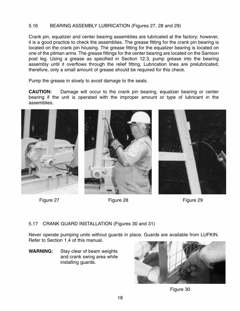
5.16 BEARING ASSEMBLY LUBRICATION (Figures 27, 28 and 29)
Crank pin, equalizer and center bearing assemblies are lubricated at the factory; however,it is a good practice to check the assemblies. The grease fitting for the crank pin bearing islocated on the crank pin housing. The grease fitting for the equalizer bearing is located onone of the pitman arms. The grease fittings for the center bearing are located on the Samsonpost leg. Using a grease as specified in Section 12.3, pump grease into the bearingassembly until it overflows through the relief fitting. Lubrication lines are prelubricated;therefore, only a small amount of grease should be required for this check.
Pump the grease in slowly to avoid damage to the seals.
CAUTION: Damage will occur to the crank pin bearing, equalizer bearing or centerbearing if the unit is operated with the improper amount or type of lubricant in theassemblies.
5.17 CRANK GUARD INSTALLATION (Figures 30 and 31)
Never operate pumping units without guards in place. Guards are available from LUFKIN.Refer to Section 1.4 of this manual.
WARNING: Stay clear of beam weightsand crank swing area while installing guards.
Figure 30
Figure 27 Figure 28 Figure 29

19
When crank guards are purchased fromLUFKIN, a crank guard installationschematic is shipped with the unit. Thisshows the panel part numbers and theirlocation relative to each other and to the wellhead. The front panel, located between theSamson post legs, heel-clamps to the basebeam flanges where possible (Figure 30).(Some bolt to front of Samson post.) Theside panel is attached to the front and rearpanels with hinges consisting of stationaryhooks on the side panels and vertical pipereceptacles on the front and rear panels.Whenever you choose to furnish your ownguards in lieu of guards available fromLUFKIN, insure they meet all Federal, State,and local laws.
5.18 ATTACHING THE WELL LOAD
Place horsehead at top of stroke. Hold the carrier bar away from the polished rod with a ropeor chain. If necessary, attach a polished rod extension to the polished rod so it will rise abovethe horsehead. From above the horsehead, slowly lift the polished rod with the crane thelength of the stroke.
WARNING: Always work the crane from above the horsehead. Catching the bottom ofthe horsehead with the crane could cause the horsehead to fall off the beam.
Remove the gate from the carrier bar and position the slot in the carrier bar around thepolished rod. Replace the gate and secure the gate latch in the notch provided. Install therod clamp at the carrier bar and tighten the bolts according to the clamp manufacturer’storque recommendations. Release the brake and slowly let the load down with the craneuntil the well load is on the unit and slack occurs in the chains. Reset the brake. Removethe rod clamp that was at the well stuffing box. Note: The pump may need to be respacedafter running the unit.
WARNING: Keep hands from between the polished rod clamp and the stuffing box in theevent the polished rod clamp slips or the unit moves.
6. PRE-OPERATION
DANGER: Before operating any unit, review the safety section (Section 1) of thismanual. Exercise extreme caution to remain clear of the crank sweep,beam weights, horsehead and other moving parts while performing anyof the following tasks.
Figure 31
20
6.1 DIRECTION OF ROTATION
The Beam Balanced pumping unit can operate equally well with the rotation it eitherdirection. Whenever evidence of excessive wear or pitting of the gear teeth is noticed, thedirection of rotation can be reversed. Reversing the rotation causes different contactsurfaces of the gear teeth to be exposed to the load, which extends the life of the gearelements. If your prime mover is a three-phase electric motor, this can easily be done byreversing the leads on the motor.
WARNING: Electrical contact can cause serious injury or death. Electrical power must belocked out prior to performing any work on the electric motor. A qualifiedelectrician must perform all electrical work.
6.2 FIRST CRANK REVOLUTION
DANGER: Contact with heavy rotating parts will cause serious injury or death.Stay clear of the crank swing, beam weights and horsehead areas.
Clear the crank swing area of all obstructions left on the unit and foundation. The firstrevolution of the crank should be as slow as possible. Check for proper clearance betweenthe beam weights and cranks from the belt cover, crank guards and pitman side members.Bottom-hole-pump spacing should also be checked during the first revolution.
After slowly rotating the unit through several revolutions, stop the unit with the horsehead atthe top of the upstroke. Set the brake. Lockout/tagout all energy sources. Install a polishedrod clamp at the stuffing box.
Recheck all bolt connections for tightness. Refer to the Section 3 for bolt tighteningrecommendations.
CAUTION: To avoid damage to the unit, all bolts must be retightened after one week ofoperation.
Remove the polished rod clamp at the stuffing box. Reverse the lockout/tagout of all energysources and release the brake. Operate the unit for 30 minutes and retighten the V-Belts.
7. COUNTERBALANCE ADJUSTMENT
7.1 DETERMINING THE REQUIRED COUNTERBALANCE
Efficient operation, minimum torque loading and maximum life of a pumping unit are all aresult of proper counterbalance. Counterbalance requirements can be determined veryaccurately or estimated by several methods.
21
DANGER: Do not enter the crank swing area or stand under the beam weights orhorsehead while performing any of the following tasks.
(1) Polished-rod dynamometer -A dynamometer card analysis is the most accurate method for determiningloading and counterbalance. This involves using a dynamometer to recordthe well load through a stroke cycle and then using torque factors todetermine the reducer torque and counterbalance required for balancedconditions.
(2) Ammeter -A clip-on ammeter may be used to compare the upstroke and down strokecurrent on electrically powered units. When the counterbalance is adjustedso the current peaks are equal, the unit will be approximately in balance.
(3) Vacuum gauge -A vacuum gauge may be used to compare torque peaks on engine drivenunits much like the ammeter is used on electrically driven units. Vacuumpressure decreases as engine output increases.
(4) Sound of the prime mover -A rough estimate of balance can be made by listening to the characteristicsound of the prime mover as it drives the unit. Some speed change will occuras the peak loads are approached; this speed change will cause the soundof the prime mover to change.
(5) Tension in the belts -Belt tension and consequently belt stretch increases with load which causesan apportionable amount of slack in the belts on the side opposite thedirection of rotation of the prime mover. A visual comparison of the belt slackor sag on the upstroke and down stroke can be used to estimatecounterbalance.
7.2 BEAM WEIGHT ADJUSTMENT
WARNING: Stay clear of the beam weights and the crank swing area and do not standunder the load while adjusting beam weights.
WARNING: Improperly tightened weight bolts can allow the beam weights to move onthe walking beam. Impact movement of the weights could break the weightbolts and damage the unit or cause serious injury or death to personnel.
22
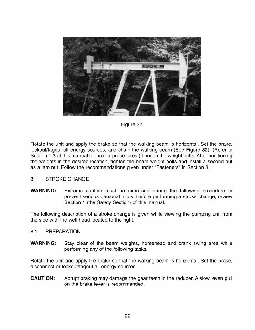
Rotate the unit and apply the brake so that the walking beam is horizontal. Set the brake,lockout/tagout all energy sources, and chain the walking beam (See Figure 32). (Refer toSection 1.3 of this manual for proper procedures.) Loosen the weight bolts. After positioningthe weights in the desired location, tighten the beam weight bolts and install a second nutas a jam nut. Follow the recommendations given under “Fasteners” in Section 3.
8. STROKE CHANGE
WARNING: Extreme caution must be exercised during the following procedure toprevent serious personal injury. Before performing a stroke change, reviewSection 1 (the Safety Section) of this manual.
The following description of a stroke change is given while viewing the pumping unit fromthe side with the well head located to the right.
8.1 PREPARATION
WARNING: Stay clear of the beam weights, horsehead and crank swing area whileperforming any of the following tasks.
Rotate the unit and apply the brake so that the walking beam is horizontal. Set the brake,disconnect or lockout/tagout all energy sources.
CAUTION: Abrupt braking may damage the gear teeth in the reducer. A slow, even pullon the brake lever is recommended.
Figure 32

23
Place a polished rod clamp at the stuffing box and tighten according to the clampmanufacturer’s torque recommendations.
WARNING: Keep hands from between the polished rod clamp and carrier bar in theevent the polished rod clamp slips or the unit moves.
Remove the crank guards and attach chains, come-a-longs or ratchet-boomers to secureboth ends of walking beam in a horizontal position (See Figure 32). Snug both come-a-longsor ratchet-boomers to restrain possible movement or tilting of the walking beam which wouldoccur once the crank pins are removed from the cranks or the equalizer is disconnedtedfrom the walking beam.
8.2 CHANGING STROKE LENGTH
Churchill model 6.4 has two adjustable stroke lengths. All other Churchill models have fouradjustable lengths (See Figure 33 and Chart on Page 24).
ChurchillUnit Size6.4 28-126.4-32-1610-32-1813-32-24*16-40-2416-53-3025-53-3025-67-3025-56-3625-67-3640-89-3640-76-4240-89-4240-76-4840-89-4850-89-42*50-89-48*50-89-54*57-89-4257-95-4857-76-5480-109-4280-109-4880-76-5480-76-64
114-143-64114-133-74114-119-86114-119-100
Adjustable StrokeLengths (inches)
12, 916,13
18,15,12,1024,19-1/2,16,13
24, 20-1/2,16,13-1/230, 24, 20,16
30, 25,19-1/2,1630, 25,19-1/2,16
36, 29, 23,1926, 29, 23-1/2,19
36, 31, 27, 2442, 35, 32, 2742, 35, 32, 2748, 41, 37, 3248, 40, 36, 3142, 35, 32, 2748, 41, 37, 3254,45, 41, 3542, 35, 32, 2748, 41, 37, 3254,45, 41, 3542, 35, 32, 2748, 41, 37, 3254, 45, 41, 3564, 54, 49, 4164, 45 ,49, 3574, 53, 57, 4186, 62, 67, 48100, 72, 77, 56
* Non API size.
24
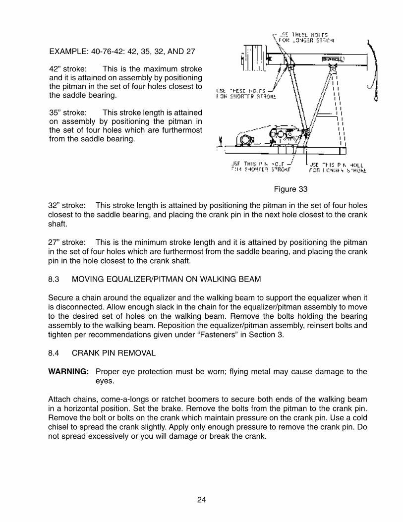
EXAMPLE: 40-76-42: 42, 35, 32, AND 27
42” stroke: This is the maximum strokeand it is attained on assembly by positioningthe pitman in the set of four holes closest tothe saddle bearing.
35” stroke: This stroke length is attainedon assembly by positioning the pitman inthe set of four holes which are furthermostfrom the saddle bearing.
Figure 33
32” stroke: This stroke length is attained by positioning the pitman in the set of four holesclosest to the saddle bearing, and placing the crank pin in the next hole closest to the crankshaft.
27” stroke: This is the minimum stroke length and it is attained by positioning the pitmanin the set of four holes which are furthermost from the saddle bearing, and placing the crankpin in the hole closest to the crank shaft.
8.3 MOVING EQUALIZER/PITMAN ON WALKING BEAM
Secure a chain around the equalizer and the walking beam to support the equalizer when itis disconnected. Allow enough slack in the chain for the equalizer/pitman assembly to moveto the desired set of holes on the walking beam. Remove the bolts holding the bearingassembly to the walking beam. Reposition the equalizer/pitman assembly, reinsert bolts andtighten per recommendations given under “Fasteners” in Section 3.
8.4 CRANK PIN REMOVAL
WARNING: Proper eye protection must be worn; flying metal may cause damage to theeyes.
Attach chains, come-a-longs or ratchet boomers to secure both ends of the walking beamin a horizontal position. Set the brake. Remove the bolts from the pitman to the crank pin.Remove the bolt or bolts on the crank which maintain pressure on the crank pin. Use a coldchisel to spread the crank slightly. Apply only enough pressure to remove the crank pin. Donot spread excessively or you will damage or break the crank.

25
8.5 CRANK PIN INSTALLATION
Use a safe solvent (per your company’s safety regulations) to clean the crank pin, crank pinhole, and the surface of the crank against which the thrust washer will seat. Also, removepaint, burrs and other foreign matter from these areas.
Adjust come-a-longs or ratchet-boomers simultaneously to line up the crank pins with theproper holes for the stroke length desired.
With a cold chisel spreading the crank arm, insert the crank pin. Remove the chisel. Insertboth bolts and tighten (if crank pin is in the hole closest to the crankshaft, snug tighten theouter bolt as overtightening will break the crank over the outer hole).
WARNING: Proper eye protection must be worn; flying metal could cause damage to theeyes.
CAUTION: Improper cleaning of the crank pin and crank pin hole, as well as impropertightening of the crank pin, can cause damage to the pumping unit.
8.6 PUTTING THE UNIT INTO OPERATION
With the brake engaged, remove the come-a-longs or ratchet-boomers.
Reinstall the crank guards. After a stroke length change, check the bottom hole pumpspacing. Also, the counterbalance should be checked and the weights repositioned asrequired for proper balancing. See Section 7 for counterbalance adjustment.
9. WELL SERVICING
DANGER: Before performing any task around a pumping unit, refer to the safetysection of this manual (Section 1). All mechanical sucker rod pumpingunits, of necessity, have rotating parts. Even a temporarily stationarypumping unit has components which can start moving from the effectof gravity. It is essential to prevent rotation of the cranks stopped inany position for the purpose of service or maintenance.
9.1 PREPARATION
WARNING: Do not attempt to service the well without first removing the horsehead.
Looking at the unit with the well head to the right, stop the unit with the cranks in about theeight o’clock position and set the brake. Lockout/tagout all energy sources.
CAUTION: Abrupt braking may damage the gear teeth in the reducer. A slow, even pullon the brake lever is recommended.
26
To clamp off the well load, place a polished-rod clamp at the stuffing box and tightenaccording to the clamp manufacturer’s torque recommendations.
Remove the crank guards.
Attach chains to the walking beam. See Notice in Section 1.3.1. Using the crane, removethe slack from the chains. Release the brake. Slowly lift the cranks until the walking beamis in a near level position. Reset the brake and chain the walking beam. (Refer to Section1.3 of this manual for proper procedures.)
Disconnect the carrier bar from the polished rod.
WARNING: Keep hands from between the polished rod and carrier bar in the event thepolished-rod clamps slips or the unit moves.
Put a long rope or chain through the carrier bar and put the gate back into the carrier bar.Be sure the rope or chain is long enough so the carrier bar can be held without lifting aperson off the ground.
9.2 HORSEHEAD REMOVAL
WARNING: Under no circumstances should well servicing be attempted without firstremoving the horsehead. Be certain to remove the latch bolt beforeattempting to remove the horsehead. Do not stand under any part of the loadwhile lifting.
Set brake; lockout/tagout and secure the walking beam and cranks from rotation. Attach thecrane to the horsehead. Remove the latch bolt. While holding the carrier bar away from thepolished rod, slowly lift the horsehead from the beam. Place the horsehead on the grounda safe distance from the work area.
Keeping the brake engaged, remove the other safety precautions for securing the unitagainst rotation. Slowly release the brake to lower the cranks to the 6 o’clock position.Reinstall safety precautions to secure the unit against rotation before well servicing.
9.3 HORSEHEAD INSTALLATION
After well servicing is completed, attach the crane to the rear of walking beam. Removesafety precautions for securing the beam and cranks, and release the brake. Slowly lift thebeam in a near horizontal position. Set the brake and chain the walking beam to secure fromany rotation. Re-attach crane to the horsehead. Reinstall the head by reversing the removalprocedure. Check the alignment of the horsehead as described in Section 5.10.
WARNING: The latch bolt must be installed and tightened at all times except duringhorsehead removal.

27
9.4 PUTTING THE UNIT INTO OPERATION
Remove the rope or chain from the carrier bar and attach the carrier to the polished rod.
WARNING: Keep hands from between the carrier bar and polished rod clamp in the eventthe polished rod clamp slips or the unit moves.
With the brake engaged, unchain the walking beam. Slowly release the brake to transferthe well load back to the carrier bar. Be sure the load is not on the polished rod clamp atthe stuffing box. Reset the brake.
Remove the polished rod clamp which was used at the stuffing box to clamp off the wellload.
Reinstall all guards before attempting to operate the pumping unit. Check the bottom holepump spacing.
10. PREVENTIVE MAINTENANCE
Preventive maintenance is essential to prolong the life of the unit and to prevent expensivefailures. Many items can be checked by visual inspection and by listening for unusualnoises. These items should be checked each time you go to the unit.
CAUTION: Never approach a pumping unit assuming that everything is all right. Withtime, some components could work loose and present a potentiallydangerous situation. Always approach operating units from the rear.
The following visual inspections are recommended before approaching the unit:
(1) Look at both crank pins to see if they may have worked loose.
(2) On units which are driven by slow-speed engines, look to see if the flywheelis loose.
(3) Look at the beam weights to be sure they are tight.
(4) Look at the center and tail bearings to be sure they have not worked loose.
(5) Inspect the vertical alignment of the unit with the well. See if the polished rodis working to one side of the stuffing box. Also, visually compare the distancebetween the pitman side-members and the cranks on each side of the unit.Check to see that the wireline is tracking properly on the horsehead. Also,look for obvious broken strands of wire fraying from the wireline. A change inalignment can be caused if the base shifts on the foundation due to loosehold-down bolts. Misalignment can also result from a foundation that hassettled to an unlevel position.

28
(6) Look for any obviously loose or missing bolts. Loose bolts will eventually failin fatigue. This is the major cause of most pumping unit failures. Loose boltscan usually be located by looking for rust at the bolted joint and by checkingfor visual movement.
If any of the above conditions exist, the unit must be shut down immediately and the problemcorrected.
WARNING: Do not perform any task on the unit until you review the safety section of thismanual (Section 1). The cranks and beam weights must be secured againstmoving.
11. SCHEDULED MAINTENANCE
There are several items that need checking on a regular basis to help extend the life of yourpumping unit.
WARNING: Always secure the cranks and beam weights against rotation or movementbefore performing any maintenance or while working around the pumpingunit. Review the safety section (Section 1) of this manual. Do not use onlythe brake as a safety stop. The brake is intended for operational use only.
11.1 MONTHLY
11.1.1 Reducer
Check the reducer oil level by using the sight gauge located in the side of the housing or adipstick located at the front of the reducer. The oil level should be between the low and fullmark on the dipstick. Loss of oil from the reducer is usually caused by seal leakage at theshafts or leakage at the parting line. If the oil level is low, remove the filler plug and add oilto the proper level. (Refer to Section 12.1 for lubricant specifications.)
11.1.2 Structural Bearing Assemblies
Visually check the crank pin bearings, equalizer bearing and center bearing for seal leaks.Do not confuse grease discharge from the bearing housing vents with seal leakage.
11.2 QUARTERLY
11.2.1 Belts and Sheaves
Belt alignment and tension should be checked and adjusted to prolong belt life. Undernormal use belts will stretch and wear. Belts need replacing once they have exceeded their
29
allowable stretch. Belt manufacturers suggest running new belts 30 minutes and thenretightening. (Consult your belt supplier.)
Also, check the sheaves for wear, chips and cracks. Replace them if any of these conditionsexist. Keeping sheaves in good condition will prolong belt life.
11.2.2.Brake
Inspect the brake lining for wear and clearance adjustment. When the brake control lever isfully engaged, there should be several notches left on the ratchet. If adjustment is required,follow the instructions in 5.3 Brake System Adjustment.
11.2.3 Brake Sheave Drum
Inspect the brake drum for cracks around the hub and key area. Look for discoloration dueto overheating. Replace the drum if any of these conditions exist. (Contact LUFKIN).
11.2.4 Brake Rods
Replace any brake rods that are bent.
11.2.5 Crank Phase Marks
On the end of the crankshaft, there is a match mark placed partially on the shaft and partiallyon the crank. These should remain lined up. If for any reason they are not lined up, youshould contact LUFKIN.
11.3 SEMI-ANNUALLY
11.3.1 Reducer
Check the gear tooth condition for abnormal wear. There are many modes of gear toothfailures. Only the most common are included in this section. The following is paraphasedfrom ANSI/AGMA 110.04, Nomenclature of Gear Tooth Failure Modes:
(1) Score marks on the teeth are an indication that the film thickness of the oil isinsufficient for the loads imposed. Score marks are vertical marks on the teethfrom the top of the teeth to the root (See Figure 34).
(2) Pitting is a type of surface fatigue which occurs when the endurance limit of thematerial is exceeded. It shows up as small cavities along the surface of the teeth.The type of pitting shown in Figure 35 is usually caused by torque overload.Continued overload may result in gear tooth failures.

30
For more detailed descriptions, illustrations, causes, and remedies, see ANSI/AGMAStandard 110.04. Note also, Figures 34 and 35 were extracted from “AGMA StandardNomenclature of Gear Tooth Failure Modes” (AGMA 110.04), with the permission of thepublisher, The American Gear Manufacturer’s Association, Suite 1000, 1901 North FortMyer Drive, Arlington, Virginia 22209.”
Before the reducer oil has a chance to settle, collect a typical sample (about a pint) in atransparent container. A visual inspection will expose possible dirt, sludge, water emulsionor other forms of contamination. Also, keep a sample of new oil for comparisons. If thelubricant has any of the following conditions, check with your oil supplier about replacement:
(1) An acid or burned odor would indicate oxidation of the oil to the point that itshould be replaced.
(2) If sludge is observed in the used sample, the oil should either be replaced orfiltered to remove the sludge. Sludge is usually found in gear units that havenot had their lubricants changed in a long time.
(3) If water is found in the sample, the water should be completely drained fromthe sump. The presence of water in used oil can be detected by placing adrop or two on a heated metal surface. Bubbling and spattering will occurwith as little as 0.1% of water present in the oil. More than approximately0.2% water by volume suggests an oil change.
Figure 34Figure 35

31
If a rigorous laboratory test of the oil is not practical, then replace the oil every 18 monthsas a precaution against a change in viscosity, a loss of the additive package or an increasein the acidic condition of the oil.
For lubricant specifications, see Section 12.1 of this manual.
11.3.2 Structural Bearings
Lubricate the structural bearings with grease as recommended in Section 12.3 of thismanual. Grease fittings are located at ground level. Pump grease in slowly to avoid pushingout the oil seals. Discharge from the vents located on each bearing housing indicates thatthe housing is full.
11.3.3 Wireline
Look for broken strands of wire fraying from the wireline. A rusty wireline should be cleanedand coated with a wireline lubricant as specified in Section 12.4.
11.3.4 Bolts
Check all bolts. Retighten as recommended in Section 3 of this manual. Loose bolts willeventually fail, which is the cause of most pumping unit failures.
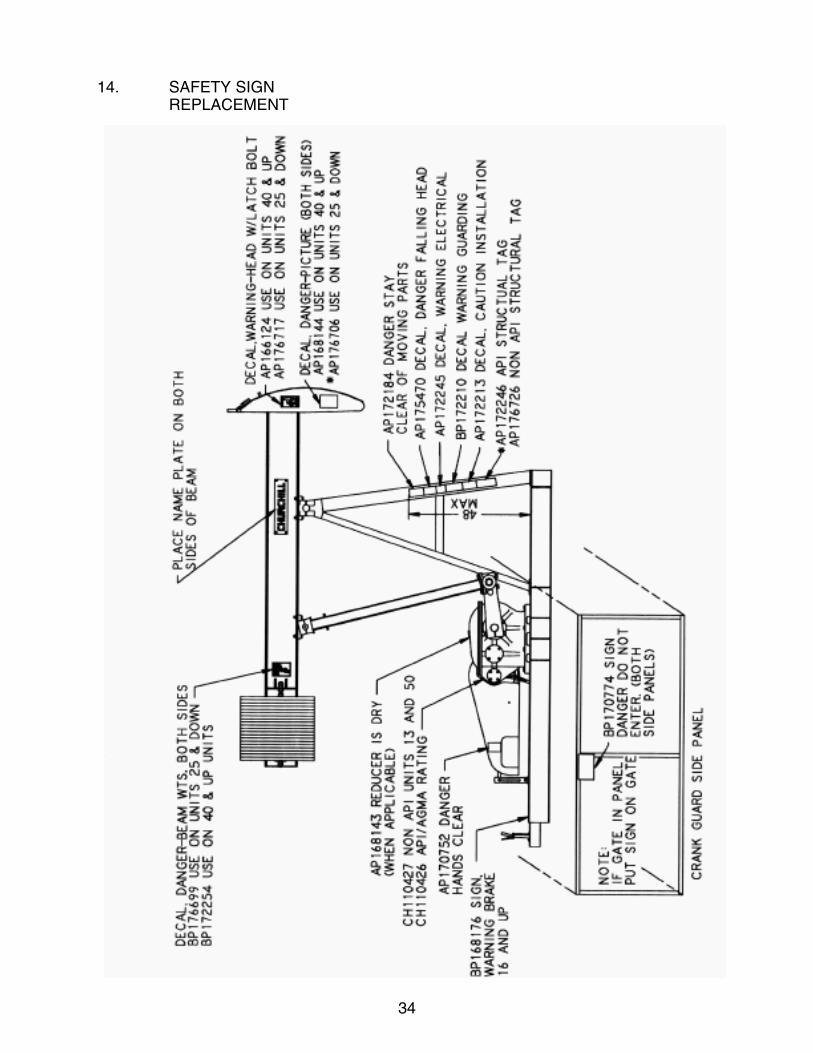
11.3.5 Safety Signs and Tags
LUFKIN uses safety signs and decals for your protection. In the event any of the signs ordecals are destroyed, damaged or become unreadable for any reason, refer to Section 14for replacement part numbers and their location on the unit.
12. LUBRICANT SPECIFICATIONS
12.1 REDUCER
For temperatures down to 0°F. use an AGMA No. 5 EP (ISO VG220) premium mild, extreme-pressure lubricant (preferably a sulphur-phosphorous type) with rust and oxidation inhibitorsand an anti-foam agent. The pour point of the oil should be 5°F. or lower. For temperaturesdown to -30°F. use an AGMA No. 4 EP (ISO VG150) premium mild, extreme-pressurelubricant (preferably sulphur-phosphorous type) with rust and oxidation inhibitors and ananti-foam agent. The pour point of the oil should be -15°F. or less.
When units are operated intermittently or shut down for periods of time while subjected toambient temperatures below 0°F, a synthetic gear lubricant may be required.
32
12.2 REDUCER OIL CAPACITY
MODEL CAPACITY
6.4D 1.00 GAL.10D 1.25 GAL.13D 1.50 GAL.16D 1.50 GAL.25D 2.00 GAL.40D 4.00 GAL.50D 4.00 GAL.57D 13.00 GAL.80D 13.00 GAL.114D 9.00 GAL.
12.3 STRUCTURAL BEARINGS
CAUTION: Do not use soda-soap grease.
For temperatures down to 0°F., use a premium NLGI No. 1 lithium,soap-base grease withan extreme-pressure additive and a base oil viscosity equivalent to AGMA No. 7(414-506cSt. at 40°C.) For extreme cold weather service (ranging from -30°F to 50°F), use apremium NLGI No. 0 lithium complex, soap-base grease with an extreme-pressure additiveand a base oil equivalent to AGMA No. 5 (198-242 cSt. at 40°C).
12.4 WIRELINE
Clean the wire rope by wire brushing; do not use solvent. Apply a good wire rope lubricantthat will penetrate and adhere to the rope.
CAUTION: Do not use crude oil or lubricants that may damage the wireline.
13. LUFKIN SERVICE
13.1 PERSONNEL
LUFKIN has capable sales and service personnel throughout the oil producing areas of theworld. These people are competent and experienced, not only in the proper sizing of surfacepumping units, but also in any service that may be needed. Contact the LUFKIN Sales Officenearest you to inquire about the availability of LUFKIN service.
13.2 REPAIR AND REPLACEMENT PARTS
WARNING: For repair or modification to a Churchill pumping unit, use only originalChurchill parts that meet LUFKIN specifications. (Consult your nearestLUFKIN sales office.)

33
A complete line of repair and replacement parts is available from several warehouselocations as well as our manufacturing plant in Lufkin, Texas. A parts list is available for mostpumping unit assemblies. When parts are needed for a particular unit, furnish the completeunit designation, serial number and LUFKIN’s shipping order number.
34
14. SAFETY SIGNREPLACEMENT

LIMITED WARRANTY
All NEW LUFKIN INDUSTRIES, INC. ("LUFKIN") oilfield machinery and equipment ("products") are sold by LUFKIN or its dealer upon the following warranty and agreement given by LUFKIN or its authorized dealer. THE WARRANTIES SET FORTH ARE EXCLUSIVE AND IN LIEU OF ALL OTHER WARRANTIES AND CONDITIONS WHETHER STATUTORY, EXPRESS OR IMPLIED, INCLUDING WARRANTIES OF MERCHANTABILITY, FITNESS FOR A PARTICULAR PURPOSE, AND WARRANTIES ARISING FROM COURSEOF DEALING, USAGE, OR TRADE and are exclusive and in lieu of any other obligation on the part of LUFKIN or its authorized dealer. LUFKIN neither assumes nor authorizes any person to assume for it any other liability in connection with the sale of such products. The obligation of LUFKIN or its authorized dealer under this warranty, is limited to the following:
• LUFKIN warrants to the ORIGINAL PURCHASER ("PURCHASER") of the pumping unit, subject to the conditions herein stated, that the pumping unit shall be, upon delivery, free from manufacturing defects. This Warranty shall run for a period of three (3) years from the date of shipment from LUFKIN's plant. In the event the pumping unit fails to operate properly due to a manufacturing defect (or) a manufacturing defect is discovered during the warranty period, LUFKIN shall only be obligated to repair or replace the pumping unit, at LUFKIN's option, free of charge, F.O.B. LUFKIN's plant, or other designated place of repair or replacement. Repair or replacement by LUFKIN shall not extend the warranty period. LUFKIN will have no liability under thisWarranty unless LUFKIN receives written notice from PURCHASER of the defect within thirty (30) days after discovery of the defect. LUFKIN may waive the requirement of written notice and accept oral notice of a timely reported defect. LUFKIN shall not be liable under this Warranty and this Warranty will be null and void if the pumping unit, or any part thereof, was damaged, subjected to abuse, altered, misused or if the pumping unit, or any part thereof, was improperly stored, installed, maintained, repaired or operated. Repair or replacement of the pumping unit, or any part thereof, shall fulfill all obligations of LUFKIN. TheWarranty provided in this paragraph is subject to the following exceptions.
• LUFKIN's warranty is limited to one (1) year (subject to the terms and conditions stated above) with respect to parts that are subject to wear under normal operating conditions (including, but not limited to contact type oil or grease seals, hoses, belts, elastomeric parts, wireline, brake lining, brake cables, etc.).
• LUFKIN extends no warranties with respect to the design of the pumping unit or the component parts, materials or accessories manufactured, furnished or supplied by individuals or entities other than LUFKIN (including, but not limited to prime movers, compressors, valves, electrical components, etc.). LUFKIN agrees that any warranty which is given to LUFKIN on such components by the manufacturer thereof shall be extended to the PURCHASER but only to the extent permitted by the terms of such warranties.
The remedies provided above are the exclusive remedies of PURCHASER for failure of LUFKIN to meet its warranty obligations,whether claims of PURCHASER are based on contract, in tort (including negligence) or otherwise. Upon expiration of the applicable warranty period, all obligations of LUFKIN for breach of warranty will terminate. The provisions of this warranty shall be governed inaccordance with the laws of the State of Texas.
Subject to and without waiving the foregoing, Purchaser agrees that neither LUFKIN, nor its affiliates, vendors, suppliers, agents, or subcontractors, either individually or jointly, shall be liable to PURCHASER, its affiliates, or any other person or entity whether due to LUFKIN's negligence or otherwise, and will not be responsible to PURCHASER in contract, in tort (including negligence) or otherwise for loss of use of equipment or plant, loss of profits or revenues, claims of any customers of PURCHASER, or any special, indirect, incidental or consequential loss of damage whatsoever. The obligation of LUFKIN arising out of the work performed hereunder, will be limited to remedies under the limited warranty set forth above. IN NO EVENT SHALL THE PURCHASER OR ANYOTHER PERSON OR ENTITY BE ENTITLED TO RECOVER FOR INDIRECT, SPECIAL, EXEMPLARY, INCIDENTAL OR CONSEQUENTIAL DAMAGES, INCLUDING BUT NOT LIMITED TO INCONVENIENCE, RENTAL OF REPLACEMENT EQUIPMENT, LOSS OF PROFITS OR OTHER COMMERCIAL OR ECONOMIC LOSS.
PURCHASER agrees to protect, defend, indemnify and save LUFKIN, its subcontractors and affiliates and their employees performingservices under this Agreement harmless from and against all liabilities, loss, expense, claims, demands, and causes of action of every kind and character arising out of or in connection with this Agreement, or the work to be performed hereunder, without limit and without regard to the cause or causes of action thereof OR THE NEGLIGENCE OF ANY PARTY OR PARTIES, INCLUDING LOSSESATTRIBUTABLE TO LUFKIN's NEGLIGENCE, arising in connection herewith in favor of PURCHASER or third parties on accountof bodily injury, death or damage to property.
PURCHASER agrees that whenever any representative of LUFKIN shall be on the premises of PURCHASER or at any place otherthan LUFKIN's facility, for the purpose of inspecting, repairing or servicing of the equipment sold herewith, the PURCHASER shall indemnify and hold LUFKIN harmless from all claims, suits or actions arising from or growing out of the inspecting, repairing or servicing of such equipment and from all expenses of defending against such claims, suits or actions.
PURCHASER acknowledges and agrees, on its own behalf and on the behalf of its assigns and successors, that the Texas Deceptive Trade Practices--Consumer Protection Act, Subchapter E of Chapter 17 of the Texas Business and Commerce Code (the "DTPA"), is not applicable to this transaction. As such, PURCHASER's and LUFKIN's rights and remedies with respect to this transaction, and with respect to all acts or practices of the other, past, present or future, in connection with this transaction, shall be governed by legal principles other than the DTPA. Accordingly, PURCHASER acknowledges and agrees as follows:
PURCHASER HEREBY IRREVOCABLY WAIVES, TO THE FULL EXTENT PERMITTED BY LAW, ANY AND ALL RIGHTS ANDCLAIMS THAT PURCHASER MAY NOW HAVE, OR TO WHICH IT MAY OTHERWISE IN THE FUTURE HAVE BEEN ENTITLED,UNDER THE TEXAS DECEPTIVE TRADE PRACTICES--CONSUMER PROTECTION ACT, TEX. BUS. AND COM. CODE § 17.41 ETSEQ., ("DTPA"), ARISING OUT OF ANY ACT, CONDUCT, REPRESENTATION OR OMISSION OF LUFKIN, ITS EMPLOYEES ORAGENTS, HERETOFORE OR HEREAFTER TAKEN, DONE OR OMITTED TO BE DONE IN CONNECTION WITH THISTRANSACTION OR SUBSEQUENT RELATED TRANSACTIONS.
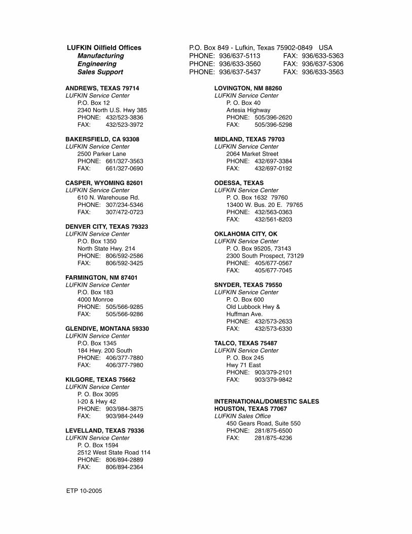
LUFKIN Oilfield Offices P.O. Box 849 - Lufkin, Texas 75902-0849 USAManufacturing PHONE: 936/637-5113 FAX: 936/633-5363Engineering PHONE: 936/633-3560 FAX: 936/637-5306Sales Support PHONE: 936/637-5437 FAX: 936/633-3563
ANDREWS, TEXAS 79714LUFKIN Service Center
P.O. Box 122340 North U.S. Hwy 385PHONE: 432/523-3836FAX: 432/523-3972
BAKERSFIELD, CA 93308LUFKIN Service Center
2500 Parker LanePHONE: 661/327-3563FAX: 661/327-0690
CASPER, WYOMING 82601LUFKIN Service Center
610 N. Warehouse Rd.PHONE: 307/234-5346FAX: 307/472-0723
DENVER CITY, TEXAS 79323LUFKIN Service Center
P.O. Box 1350North State Hwy. 214PHONE: 806/592-2586FAX: 806/592-3425
FARMINGTON, NM 87401LUFKIN Service Center
P.O. Box 1834000 MonroePHONE: 505/566-9285FAX: 505/566-9286
GLENDIVE, MONTANA 59330LUFKIN Service Center
P.O. Box 1345184 Hwy. 200 SouthPHONE: 406/377-7880FAX: 406/377-7980
KILGORE, TEXAS 75662LUFKIN Service Center
P. O. Box 3095I-20 & Hwy 42PHONE: 903/984-3875FAX: 903/984-2449
LEVELLAND, TEXAS 79336LUFKIN Service Center
P. O. Box 15942512 West State Road 114PHONE: 806/894-2889FAX: 806/894-2364
LOVINGTON, NM 88260LUFKIN Service Center
P. O. Box 40Artesia HighwayPHONE: 505/396-2620FAX: 505/396-5298
MIDLAND, TEXAS 79703LUFKIN Service Center
2064 Market StreetPHONE: 432/697-3384FAX: 432/697-0192
ODESSA, TEXAS LUFKIN Service Center
P. O. Box 1632 7976013400 W. Bus. 20 E. 79765 PHONE: 432/563-0363FAX: 432/561-8203
OKLAHOMA CITY, OKLUFKIN Service Center
P. O. Box 95205, 731432300 South Prospect, 73129PHONE: 405/677-0567FAX: 405/677-7045
SNYDER, TEXAS 79550LUFKIN Service Center
P. O. Box 600Old Lubbock Hwy &Huffman Ave.PHONE: 432/573-2633FAX: 432/573-6330
TALCO, TEXAS 75487LUFKIN Service Center
P. O. Box 245Hwy 71 EastPHONE: 903/379-2101FAX: 903/379-9842
INTERNATIONAL/DOMESTIC SALESHOUSTON, TEXAS 77067LUFKIN Sales Office
450 Gears Road, Suite 550PHONE: 281/875-6500FAX: 281/875-4236
ISSUED: month/date/2002
ETP 10-2005