cigre guide for transformer fire safety practices
TRANSCRIPT

537
Guide for Transformer Fire Safety Practices
Working Group
A2.33
June 2013

i
GUIDEFOR
TRANSFORMER FIRE SAFETY PRACTICES
Working Group A2.33
Members:Arne PETERSEN (AU) – ConvenorRudy BLANC (FR)Kjell CARRANDER (SE)Dayse DUARTE (BR)Yoshihito EBISAWA† (JP)Elisa J. FIGUEROA (CA)Marc FOATA (CA)Makoto KADOWAKI (JP)Takayuki KOBAYASHI (JP)Terence LEE (US)Russell MARTIN (UK)Sidwell MTETWA (ZA)Hiroshi MURAKAMI (JP)Uwe RIMMELE (DE)Yukiyasu SHIRASAKA (JP).
I memory of Yoshihito Ebisawa san,“ Ebi” as he was known to his friends made significant contribution to the completion of thisbrochure. Ebi passed away on the 27.12.2012 after the brochure was completed, but before itcould be published. The members of the WG who worked with Ebi will remember him forexceptional competences, his intellectual rigor, and by his remarkable elegance and charm.
Copyright © 2012Ownership of a CIGRE publication, whether in paper form or on electronic support only infers right of usefor personal purposes. Are prohibited, except if explicitly agreed by CIGRE, total or partial reproductionof the publication for use other than personal and transfer to a third party; hence circulation on anyintranet or other company network is forbidden”.
Disclaimer notice
“CIGRE gives no warranty or assurance about the contents of this publication, nor does it accept anyresponsibility, as to the accuracy or exhaustiveness of the information. All implied warranties andconditions are excluded to the maximum extent permitted by law”.

ii
SUMMARY
The issue of transformer fire safety has been of concern to Cigre SCA2 for some time and it wasevident from discussion of the topic within the Study Committee that the probability and risk ofa transformer fires and the effectiveness of the various risk mitigation measures was not alwayswell understood by many transformer users and other stakeholders.
SCA2 therefore decided to establish a working group [WG A2.33] to prepare recommendationsfor good Transformer Fire Safety Practices that would help transformer designers and users todefine and apply best practices in the domain of transformer fire.
The working group WG A2.33 has endeavoured to do this by preparing this Technical Brochurewhich covers the following aspects of transformer fire safety:
Chapter 1 : An introduction to Transformer fire Safety issues with listing of useful Standardsand Guide Documents with information on Transformer Fire Safety.
Chapter 2 : Physics of fires and typical transformer fire scenarios to give a broad perspective ofthe concepts and issues related to transformer fires.
Chapter 3: Providing guidance on the probability of a transformer fire event occurring based oninformation available in the public domain and also on how a transformer user might be able toassess the probability of a transformer fire event occurring in its transformer population.
Chapter 4 : Discusses the physics of arcing within transformer tank and gives formulas andexamples on how a user might be able to predict the likely range of arcing energy, volume of gasgenerated and likely pressures which might be developed during an internal arcing event. Thechapter also provides examples on pressure calculation models which are available forapproximate calculation of the pressures which may be developed during and arcing fault withsome examples on pressure venting and pressure containment. Although it must be stressed it isnot possible to ensure with absolute certainty that the arcing energy can be contained within thetransformer tank at high energy arcing faults.
Chapter 5 : Provides guidance on issues to consider when determining what fire protection maybe required and what should be installed at a specific site. It gives examples on points toconsider when determining the likely performance of fire protection systems and providesexamples on the methodologies available when planning and designing a fire protection systemfor a transformer installation.
Chapter 6: Discusses the risk mitigation options available for the transformer, and providessome guidance on the ranking of the options based the risk reduction effectiveness and thedegree of risk reduction required for the specific installation.-
Chapter 7 : Discusses the risk mitigation options available for the substations and othertransformer installations to protect human life, maintain supply or if not possible minimise lossof supply and to protect adjacent plant and equipment.
Chapter 8 : Provides advice on planning and the importance of being prepared for a fire event, soas to minimise the effects and losses from a fire and be able to recover from the fire as early aspossible.
Chapter 9 : Contain conclusions and some recommendation for improvement on Standards forimproved fire safety on tanks and cable boxes.

Guide for Transformer Fire Safety Practices
iii
TABLE OF CONTENTSChapter 1: Introduction................................................................................................ 1
1.1 Scope........................................................................................................................... 11.2 Risk Context ................................................................................................................11.3 Types of Transformers Considered...............................................................................21.4 Types of Transformer Installations Considered ............................................................ 31.5 Standards and Guides...................................................................................................3
Chapter 2: Fire Physics and Typical Transformer Fire Scenarios ............................ 52.1 Fire Risk...................................................................................................................... 5
2.1.1 Heat Energy - Electrical .........................................................................................52.1.2 Heat Energy - Chemical .........................................................................................62.1.3 What is a Fire? .......................................................................................................62.1.4 Combustion............................................................................................................62.1.5 Explosion...............................................................................................................7
2.2 Fire Scenarios ..............................................................................................................72.2.1 Internal Arcing Fault ..............................................................................................82.2.2 Tank Rupture Process...........................................................................................102.2.3 Transformer Bushing Fire Scenarios.....................................................................112.2.4 Transformer Cable Box and Cable Termination Failures Fire Scenarios ................132.2.5 The Effect of a Transformer Fire in a Substation...................................................152.2.6 Classification of Fires and Extinguishing Agents ..................................................162.2.7 Fire Resistance Classification ...............................................................................162.2.8 Extinguishment of Fires........................................................................................162.2.9 Transformer as a Fire Victim................................................................................17
Chapter 3: Probability of a Transformer Fire............................................................ 183.1 Transformer Failure Rates from Survey Data ............................................................. 18
3.1.1 CIGRÉ Failure Survey .........................................................................................183.1.2 CIGRÉ Australia – New Zealand Reliability Survey.............................................193.1.3 Surveys on Major Transformer Failures by Manufacturer .....................................213.1.4 CIGRE Australia 2002 Survey on Major Transformer Failures and Fires ..............223.1.5 Transformer Failure Rate Russia and Ukraine.......................................................223.1.6 Power Transformer Fire Risk Assessment by a Major Canadian Utility.................223.1.7 Transformer Failure and Fire Risk Rate in Japan...................................................243.1.8 Insurance Company Experience............................................................................253.1.9 Transformer Failure and Fire Risk Rate - Data Other Sources ...............................25
3.2 Major Causes of Transformer Fire.............................................................................. 263.2.1 Transformer Fire Initiated by Bushings and Cable Termination Failures ...............263.2.2 OIP Bushing Initiated Fires ..................................................................................263.2.3 Fires Initiated by Cable Termination Failures .......................................................263.2.4 Fires Initiated by OLTC Failures ..........................................................................263.2.5 Fires Initiated by a Tank Rupture..........................................................................27
3.3 The Probability of Transformer Fires - Summary ....................................................... 273.4 The Risk to Potential Fire Victims – Other Substation Assets ..................................... 29
Chapter 4: Internal Arcing and Tank Ruptures......................................................... 314.1 Arc Energy ................................................................................................................ 314.2 Gas Generation .......................................................................................................... 334.3 Pressure Calculation Models ...................................................................................... 34
4.3.1 Simplified Containment Model.............................................................................34

Guide for Transformer Fire Safety Practices
iv
4.3.2 Simplified Venting Model ....................................................................................354.3.3 Hydrodynamic Numerical Models ........................................................................364.3.4 Structural-Hydrodynamic Numerical Models........................................................36
4.4 Pressure Containment ................................................................................................ 374.5 Pressure Venting........................................................................................................ 38
4.5.1 Theoretical Upper Bound Analysis .......................................................................394.5.2 Venting Simulation ..............................................................................................42
Chapter 5: Fire Risk and Performance Analysis ...................................................... 445.1 Introduction ............................................................................................................... 445.2 Performance Analysis ................................................................................................ 445.3 Understanding the Problem and Identifying System Features ..................................... 445.4 Evaluating Performance and Risk Characterization .................................................... 475.5 Structuring a Fire Risk Management Program ............................................................ 475.6 Evaluate Prevention ................................................................................................... 485.7 Emergency Planning .................................................................................................. 505.8 Decision Analysis and Management Decisions........................................................... 505.9 Consequences of Transformer Fires ........................................................................... 515.10 Case Study of a Pool Fire on a Transformer with 40,000 l of Mineral Oil ................... 545.11 Conclusions ............................................................................................................... 60
Chapter 6: Fire Risk Mitigation Options for Transformers ...................................... 626.1 Introduction ............................................................................................................... 626.2 Minimizing the Risk of Transformer Fires.................................................................. 62
6.2.1 Standard Tanks with Pressure Safety Margin above PRV Opening Pressure..........636.2.2 Enhanced Maintenance Practices ..........................................................................636.2.3 Operating Practices ..............................................................................................64
6.3 Protection .................................................................................................................. 646.3.1 Electrical Protection .............................................................................................646.3.2 Overvoltage Protection.........................................................................................66
6.4 Less-Flammable Insulating Media.............................................................................. 666.4.1 Dry Type Transformers ........................................................................................666.4.2 Gas Insulated Transformers (GIT) ........................................................................66
6.5 Less Flammable Insulating Fluids .............................................................................. 686.5.1 Properties of Less-Flammable Fluids ....................................................................696.5.2 High Molecular Weight Hydrocarbon (HMWH)...................................................706.5.3 Synthetic Esters....................................................................................................716.5.4 Natural Esters.......................................................................................................716.5.5 Silicone Oil ..........................................................................................................716.5.6 Combustion Characteristics and Test Results ........................................................72
6.6 Tank Design as Protective Strategy ............................................................................ 746.6.1 General ................................................................................................................746.6.2 Tank Strength Requirements.................................................................................756.6.3 Tank Design.........................................................................................................756.6.4 Improvement of the Tank Strength .......................................................................766.6.5 Pressure Reducing Techniques .............................................................................766.6.6 Gas Cushion Transformers ...................................................................................786.6.7 Verification of Pressure Withstand Capability ......................................................78
6.7 Pressure Venting & Depressurization as Protective Strategies .................................... 786.7.1 Goose Neck Explosion Vent.................................................................................796.7.2 Pressure Relief Valves (PRV)...............................................................................796.7.3 Rupture Discs.......................................................................................................80

Guide for Transformer Fire Safety Practices
v
6.7.4 Tank Protection Systems Based on Rupture Discs and Nitrogen Injection .............806.7.5 Tank Protection Systems Using Multiple Rupture Discs .......................................81
6.8 Choice of Components as Protective Strategies .......................................................... 826.8.1 Bushings ..............................................................................................................826.8.2 Cable Terminations and Cable Boxes ...................................................................826.8.3 Insulating Liquid Filled Cable Boxes....................................................................826.8.4 Air Insulated Cable Boxes ....................................................................................836.8.5 SF6 Connection....................................................................................................836.8.6 Conservator Shut-off Valve ..................................................................................836.8.7 Tap Changers .......................................................................................................83
Chapter 7: Transformer Fire Damage Control Practices ......................................... 857.1 Introduction ............................................................................................................... 857.2 Standards and Guides................................................................................................. 867.3 Fire Control Measures................................................................................................ 86
7.3.1 Minimising the Risk of Loss of Life to Humans....................................................867.3.2 Passive Protection Systems...................................................................................877.3.3 Fire Barriers / Walls .............................................................................................917.3.4 Oil Containments .................................................................................................967.3.5 Active Fire Suppression Systems........................................................................1007.3.6 Indoor City Substations ...................................................................................... 106
7.4 Underground Substations ......................................................................................... 1127.5 Highest Impact Strategies......................................................................................... 113
7.5.1 Outdoor Substations ........................................................................................... 1137.5.2 Indoor Substations.............................................................................................. 113
Chapter 8: Plans for a Fire Event ............................................................................ 1158.1 The Importance of Planning for a Fire Event ............................................................ 1158.2 Contingency Planning.............................................................................................. 1158.3 Emergency Response Plan ....................................................................................... 116
8.3.1 Emergency Response Policy...............................................................................1168.3.2 Members of the Emergency Response Team....................................................... 1178.3.3 Pre-Incident Planning with Emergency Services .................................................119
8.4 Disaster Recovery Plan ............................................................................................ 1208.5 Business Continuity Plan ......................................................................................... 1228.6 Summary ................................................................................................................. 122
Chapter 9: Conclusions and Recommendations.................................................... 1239.1 General .................................................................................................................... 1239.2 Actions to Avoid a Fire ............................................................................................ 123
9.2.1 Electrical Protection ........................................................................................... 1239.2.2 Bushings ............................................................................................................1239.2.3 Cable Boxes and Terminations ...........................................................................1239.2.4 Tanks .................................................................................................................1249.2.5 Alternative Insulating Media ..............................................................................125
9.3 Actions to Mitigate the Damage of a Fire ................................................................. 1259.4 Recommendations for Future Work.......................................................................... 126
References.............................................................................................127References - Addendum.................................................................................130

Guide for Transformer Fire Safety Practices
vi
Table of Figures
Figure 1: Fire Triangle ................................................................................................................5Figure 2: Tank Rupture Process................................................................................................. 11Figure 3: Typical Bushing Fire Scenario [22] ............................................................................ 13Figure 4: Cable Box and Cable Termination Fire Scenarios ....................................................... 14Figure 5: Transformer Failure Rate according to Component and Voltage level Australian New
Zealand Reliability Survey - 1995........................................................................... 20Figure 6: Yearly Failure rate according to age Australian New Zealand Reliability Survey - 199521Figure 7: Arc voltage as a function of arc length [29] ................................................................ 31Figure 8: Example of arc energy calculation (8 MJ) based on actual fault voltage and current
measurements......................................................................................................... 32Figure 9: Comparison of gas generation models and experiments from different authors (Gas
volume at Normal Pressure and 2000 K) ............................................................... 34Figure 10: Variation of the dynamic amplification factor F for Equation 3................................. 35Figure 11: Simplified numerical model for venting to adjacent tanks ......................................... 35Figure 12: Example of pressure field calculation outputs from hydrodynamic models ................ 36Figure 13: Example of stress field outputs from an explosive simulation of the arc .................... 37Figure 14: Example of a real chimney rupture case with an arc simulation methodology............ 37Figure 15: Upper bound for venting efficiency (% peak pressure reduction) Arc (3 cycles
duration) located in the immediate vicinity of the aperture ...................................... 40Figure 16: Upper bound for venting efficiency (% pressure reduction) Arc (3 cycles duration)
located more than 1 m from the aperture ................................................................. 41Figure 17: Upper bound for venting efficiency (% pressure reduction) Arc (30 cycles duration)
not located within the immediate vicinity of the aperture ........................................ 42Figure 18: Transformer equipped with a 40 rupture discs depressurization system ..................... 43Figure 19: Performance Fire Risk Management ......................................................................... 45Figure 20: Understanding the problem....................................................................................... 46Figure 21: Transformer Fire Performance.................................................................................. 47Figure 22: Reliability of the Water Spray Systems..................................................................... 49Figure 23: Evaluation of Water Spray Systems .......................................................................... 50Figure 24: Success or Failure of the Agent Application ............................................................. 50Figure 25: A transformer involved in a pool fire ........................................................................ 51Figure 26: A Pool Fire Transformer Superimposed on Transformer Bay.................................... 55Figure 27: Layout of the substation ........................................................................................... 57Figure 28: Deformation of the High Voltage Landing Span Structure after a Transformer Fire... 58Figure 29: Case 1: Temperature versus time and load-bearing capacity versus time graphs to an
exposed energy of 19 kW/m² .................................................................................. 59Figure 30: Case 2: Temperature versus time and load-bearing capacity versus time graphs to an
exposed energy of 20 kW/m² .................................................................................. 60Figure 31: Case 2: Temperature versus time and load-bearing capacity versus time graphs to an
exposed energy of 7 kW/m² .................................................................................... 60Figure 32: GIT Structure and Features....................................................................................... 67Figure 33: GIT Application Range ............................................................................................ 68Figure 34: Comparative Combustion Test Results ..................................................................... 73Figure 35: Ideal protective performance of a PRD time......................................................... 75Figure 36: Example of reinforcement at joining flanges ............................................................. 76Figure 37: Pressure reduction effect of an expansion volume ..................................................... 77

Guide for Transformer Fire Safety Practices
vii
Figure 38: Comparison between Dynamic and Static Pressure Testing....................................... 78Figure 39: Variations in the recommended separation distance between transformer tank and
other assets. ............................................................................................................ 87Figure 40: Wind direction effect on temperature - distance contours. ......................................... 88Figure 41: Suggested separation distances. ................................................................................ 91Figure 42: Fire Barrier protecting two adjacent transformers...................................................... 92Figure 43: Zone of exposure downwind of burning transformer ................................................. 93Figure 44: Exposed building roof downwind of burning transformer.......................................... 93Figure 45: Extending building wall to protect exposed roof section............................................ 94Figure 46: Side elevation of exposed area of a tall building........................................................ 94Figure 47: Front elevation of exposed area of a tall building ...................................................... 95Figure 48: Fire on 80 MVA Transformer in sound enclosure ..................................................... 96Figure 49: Example of an Oil-Water separation tank.................................................................. 97Figure 50: Alternative Oil-Water separation system................................................................... 98Figure 51: Oil separator installation........................................................................................... 98Figure 52: Rock filled pit arrangement ...................................................................................... 99Figure 53: Typical water spray arrangement for transformer and oil containment area ............. 101Figure 54: Water spray system with rock filled pit ................................................................... 101Figure 55: Water curtain protection in Japan............................................................................ 102Figure 56: Oxygen percentage effect on fire intensity and haemoglobin saturation................... 103Figure 57: Transformer sound enclosure with Nitrogen gas fire protection............................... 105Figure 58: Fire Suppression system using inert gas on transformers installed within sound
enclosure panels ................................................................................................... 106Figure 59: Internal design of a city substation with fire protection consideration...................... 109Figure 60: SF6 underground substation in Sydney [63]............................................................ 111Figure 61: Loss analyzed for contingency planning (Average loss totals in US$ Millions) ....... 115Figure 62: The impact of effective emergency response........................................................... 116Figure 63: Situation where no Emergency Response Plan was in place. ................................... 120

Guide for Transformer Fire Safety Practices
viii
Table of Tables
Table 1 : Summary of CIGRE 1983 Power Transformers Failure Survey ................................... 19Table 2 : CIGRÉ Australia – New Zealand Reliability Survey ................................................... 19Table 3 : Statistics by a major Canadian Utility 1965 -1985: Fire rate ........................................ 23Table 4 : Statistics by a major Canadian Utility 1965 -1985: Explosion vs. Fire ......................... 23Table 5 : Statistics by a major Canadian Utility 1965 -1985: Fault Location vs. Fire Rate .......... 23Table 6 : Arc Energy versus Consequences (735 kV Transformers and Reactors) ...................... 24Table 7 : Transformer Failure and Fire Risk Rate - Data Other Sources............................. 25Table 8 : Measured Gas Generation Rate ................................................................................... 33Table 9 : Approximate range of arc energy containment capability of three phase transformer
with conventional tank designs ............................................................................... 38Table 10 : Radiated energy (kW/m²) on a target from a transformer pool fire ............................. 54Table 11 : Thermal flux impact from transformer fire of 7 kW/m2 ............................................. 56Table 12 : Exposure time necessary to reach pain threshold [50]................................................ 56Table 13 : Time to failure of the structure members in case 1 and 2 ........................................... 59Table 14 : Typical Characteristics of Insulating Liquids............................................................. 70Table 15: Pressure reducing effect of multiple rupture discs ...................................................... 81Table 16 : IEC 61936-1 2002 Recommendations for separation distances between outdoor
transformer and buildings ....................................................................................... 89Table 17 : FM Global’s recommendations for separation distances between outdoor transformer
and buildings.......................................................................................................... 89Table 18 : FM Global’s recommendations for separation distance between outdoor transformers90Table 19 : ENA Document 18.-2008, Recommendation for separation distance between outdoor
transformer and equipment ..................................................................................... 90Table 20: Responsibilities of the Emergency Response Team .................................................. 118Table 21 : Responsibilities of the Disaster Recovery Team ...................................................... 121

Guide for Transformer Fire Safety Practices
1
Chapter 1: Introduction
1.1 ScopeThe risk of a transformer causing a fire is low, but not negligible and the consequences can be verysevere if it does occur. The aim of this brochure is to promote “Good Fire Safety Practices”. Itendeavours to do this by:
Presenting typical transformer fire scenarios,
Quantifying the probability of transformer fires and tank ruptures,
Discussing internal arcing, and possible measures which reduce the risk and consequences ofa transformer fire.
Presenting practical and cost effective strategies for fire prevention and for control and riskmitigation measures which can be applied to both transformers and transformer installations. Thebrochure is intended for use by transformer users and engineers who specify and design transformersand transformer installation. Its aim is to help-them define and apply best practices in the domain oftransformer fire safety.
However, this guide does not replace the relevant national, provincial or local regulations which mustbe considered, and where mandatory, complied with.
The brochure assumes that the reader has a basis understanding of transformer technology andsubstation installations.
Avoidance of tank rupture and containment of oil is critical for limiting the consequences of atransformer failure and reducing the risk that a minor transformer fire escalates into a major orcatastrophic oil fire. The objective of this brochure therefore includes defining key parametersinfluencing tank ruptures. Results obtained by model simulation, laboratory testing and experiencesduring service life are presented to give an overview of the state-of-the-art in that domain.
We separate two different situations 1) where a transformer may catch fire, i. e. causing the fire and2) being victim to a fire originating elsewhere. In this brochure we concentrate on the case where thetransformer is the origin of the fire and the transformer installation and adjacent assets may becomevictims to a fire caused by the transformer.
The case when the transformer is the victim of the failure is also of concern. If an external fire isgiven sufficient time to heat up the transformer liquid so much that the liquid is spilled over via theconservator, then the external fire will be strengthened if the transformer is oil filled or contains othercombustible liquid.
However, the case where the transformer is a victim to a fire originating elsewhere will not becovered here in any details.
1.2 Risk ContextRisk is defined as: Probability x Consequence
The risk of a transformer fire is therefore the probability of the event happening and theconsequential destruction of the transformer and potentially other assets, environmental pollution anddamage, loss of supply and in extremely rare cases loss of human life. The term “risk” is often usedloosely and synonymously with the probability of or chance of an event such as a transformer fire,

Guide for Transformer Fire Safety Practices
2
rather than strictly as defined above. This is also the case in the remainder of this document; howeverthe meaning will be evident from the context of where the term is used.
The probability of transformer fires are in the order of 0.1 % per transformer service year i.e. 1 fireper 1000 in service transformers per year. This is not a high probability, but the consequence isnearly always total loss of the transformer and often with collateral damage to other adjacent assetsand often with some environmental pollution and loss of supply for various durations. Also whilst 0.1% may appears low, the accumulated probability of the event happening is on average in the order of4 % per transformer over a typical service life of 40 years.
The risk is therefore not negligible and it is certainly too high to ignore and do nothing.The probability of transformer fires varies considerably among utilities and even among types oftransformers within the same utility. Some utilities have significantly higher and some significantlylower numbers of transformer fires than the average probability. Similarly some utilities may havetypes or voltage classes of transformers which have much higher probability of causing fires thanothers types.
When a transformer failure results in a fire the transformer will often be damaged to a degree whererepair is not economic. The aim is therefore not to save the transformer if a transformer fire occurs,but rather:
To prevent and minimise consequential damage to the substation installation and other plantitems located in the vicinity of the transformer on fire.
To avoid loss of supply from the substation and if not possible then to minimise the time ofloss of supply.
To minimise and if possible avoid pollution and contamination to the surroundingenvironment. Especially the environment outside the substation boundary. The potentialpollution includes both airborne pollution in form of smoke, soot and noxious fumes andrunoff causing ground water contamination by oil or other chemicals including foams andother fire-suppressant chemicals which may be used in fire fighting.
The probability and the consequential risk of transformer fires will be discussed morecomprehensively in Chapter 3: of this brochure.
1.3 Types of Transformers ConsideredThe scope of this document is for transformers > 10MVA and rated > 66 kV. However, much of thediscussion and many of the recommendations will also be applicable for transformer of lower ratings.
The main focus is on mineral oil immersed transformers, comprising an electrical grade laminatedsteel core, with Kraft paper and/or enamel covered copper or aluminium winding conductors wherethe active parts is contained within an oil filled steel tank. The design and construction oftransformers is not discussed in this brochure and it is assumed that the reader is familiar with typesof transformers which are within the scope of this brochure.
Much of the content of this brochure is equally applicable to industrial and other special purpose oilimmersed transformers. However, some of these transformers have special features and installationrequirements, which require specific attention and special requirements which may not be covered inthis brochure.
Oil immersed reactors are not discussed as a separate item, however it can be considered all thediscussions and recommendations made for oil immersed transformers are equally applicable to oilimmersed shunt and series reactors.

Guide for Transformer Fire Safety Practices
3
Other form of insulating liquids is used in transformers for fire risk mitigation and/or environmentalreasons. Most of these fluids are high flame point fluids which have lower but not zero fire risk.These fluids will be discussed in Chapter 5: of this brochure in the context of fire risk mitigation.
Gas Insulated Transformers using SF6 gas as the cooling and insulation medium is the only type oftransformer with virtually a zero fire risk.
1.4 Types of Transformer Installations ConsideredThe fire safety precautions to be taken at transformer installations are in the context of this documentthat the installation is being a “Victim” of a fire originating in or at the transformer. The precautionstaken at transformers installation may not have much impact on reducing the likelihood of thetransformer failing and causing a fire, but it can be a very important factor in limiting theconsequential damage to the installation or other plant items located in the substation and to theduration of loss of supply to customers. Transformer fire safety is therefore an importantconsideration when specifying and designing both transformers and transformer installations.
The degree of fire safety measures required and the practical and cost effective solutions applicable atsuch installations varies enormously depending on the type and location of the specific transformerinstallation; from a remotely located open air low land cost transmission substation, to compacthigher land cost open air an urban bulk supply substation or an indoor city substation located at thelower levels of a high rise office building or a power station generator step transformer or industrialtransformer in close proximity to high cost industrial installation. It is therefore useful to categorisecommon types of transformer installations and discuss the considerations and the recommended firesafety measures to be taken at each type of installation separately.
Good fire safety practices applicable for each of the types of installations listed above will bediscussed in details in Chapter 7:
1.5 Standards and GuidesA list of standard and guides which provide relevant guidance on transformers and fire safety issuesrelated to transformers include, but is not limited, to the following publications:
IEC 60076-1 Power transformers – Part 1 General [1] IEC 60137 Bushings for alternating voltages above 1000 V [2] IEC 61936-1 Power installation exceeding 1 kV AC Part 1: Common rules [3] ENA DOC 18-2008 Interim Guide for the Fire protection of Substations [4] NFPA Fire Protection Handbook 2008 [5] NFPA 70 National Electrical Code Article 450 [6] Australian/New Zealand Standard AS/NZS 3000:2000 Wiring Rules Section 7.8.8. [7] NFPA 850 Recommended Practice for Fire Protection for Electric Generating Plants and
High Voltage Direct Current Converter Stations, 2010 Edition [8] NFPA 851 Recommended Practice for Fire Protection for Hydroelectric Generating Plants,
2010 Edition [9] IEEE 979 Guide of Substation fire protection [10] IEEE 980 INT 1-3 Guide for Containment and Control of Oil Spills in Substations [11] FM Global Property Loss prevention Data sheet 5-4 Transformers May 2010 [12] US Department of Interior Department of Reclamation Facilities Instructions, Standards and
Techniques, Vol. 3-32 Transformer Fire Protection [13] NGTS 2.20 Oil Containment in Substations [14]

Guide for Transformer Fire Safety Practices
4
NGTS 3.1.3 Limitation of Fire Risk in Substations [15] CEATI Report No.T023700-3022 - Transmission Stations and Transformers - Fire Protection
and Prevention [16] Electrical Cooperative Research, Japan No 40-5 Design Guide for Tanks [17] (in Japanese)
see CIGRÉ Summary Paper 12.02 1988 EPRI Report TR-104994 Power Transformer Tank Rupture: Risk Assessment and mitigation
[18] RTE Dispositions Type Postes (Design specifications for substations) [19] IEC/TC10 Classification of Insulation Liquids According to Fire Behaviour [20]

Guide for Transformer Fire Safety Practices
5
Chapter 2: Fire Physics and Typical Transformer FireScenarios
2.1 Fire RiskFires are depending of the control of heat energy, oxygen and fuel.
The fire triangle provides very good graphic representation of what is required to initiate andmaintain a fire and therefore also how a fire can be prevented or extinguished.
For a fire to exist and propagate, it requires thethree key elements of Heat, Fuel and Oxygen inwell defined ratios.
Without oxygen there will be no fire. Without heat there will be no fire. Without fuel there will be no fire.
Figure 1: Fire Triangle
If anyone of these three elements is absent then the fire will not start, or if removed after a fire hasstarted then the fire will extinguish.
It is therefore useful to consider the common ways heat can be produced in the context of transformerfire safety i.e. in addition to the heating produced from load and no load losses.
Two such sources of heat energy are of particular interest (1) Electrical (2) Chemical.
2.1.1 Heat Energy - ElectricalElectrical Heat Energy sources include:
Resistance Heating – this is always present in electrical equipment and can become excessive andcause fires in transformers if high resistance joints develop, if overloading occurs, or if cooling isdiminished due to failure in cooling equipment or obstruction of flow of cooling medium.
Induction Heating – this occurs in transformer tanks and structures due to magnetic fields fromleakage flux and also high currents in conductors in proximity to magnetic metals. It can becomeexcessive, if overloading occurs or cooling is diminished.
Dielectric Heating – this occurs in dielectric materials when exposed to dielectric stress. It canbecome excessive and reach thermal run away, if the dielectric stresses become excessive ordielectric properties deteriorates or cooling is inadequate. The dielectric heating of concern intransformers is mainly with HV bushings and HV cable terminations, where it can cause thermalrunaways, especially as dielectric properties deteriorates with age and increased moisture level.Bushing and cable termination failures cause the greatest number of transformer fires, although manyof these failures are not necessarily due to dielectric heating.
Heating from Arcing – this is the main cause of transformer fires. Arcing occurs when the dielectricmaterials cannot withstand the dielectric stress imposed on it and a breakdown resulting in an arcdeveloping between two electrodes occurs. The arc provides a low resistance path and causes a veryhigh current to flow between the two electrodes. The energy in the arc can be very high, typically inthe kilo - Mega Joule range and develop temperatures in thousands of degrees.

Guide for Transformer Fire Safety Practices
6
Heating from static electricity - is unlikely to cause fires as it is of low energy. However, staticelectric charge is known to have cause dielectric breakdown resulting in internal arcing and failure oftransformers.
Heating from Lighting Strikes - is unlikely to cause fires in transformers, but transient overvoltagefrom lightning can cause dielectric breakdown, leading to failure and potentially a fire in sometransformers.
2.1.2 Heat Energy - ChemicalChemical heat energy is a product of all fires. It can be present in several forms including bothexplosion and combustion.
Explosion produces heat due to chemical changes. An explosion is a rapid release of energy in anextreme manner usually with the generation of high temperatures, release of gases and rapid increasein volume/ pressure in the generated gases.
A high current electrical fault can create an electrical explosion by forming a high energy electricalarc which rapidly vaporizes metal and insulation material. It is the rapid liberation of heat that causesthe gaseous products of most explosive reactions. It causes the gases to expand and also generateshigh pressures. It is this rapid generation of gases under high pressures and the expansion of thegases, which constitutes the explosion and creates a shock wave.
If the shock wave is a supersonic detonation, then the source of the blast is called a "high explosive".Subsonic shock waves are created by low explosives, through the slower burning process known asdeflagration.
Heat of Combustion - this occurs in fires and can be a complete or partial oxidation of a fluid or solidmaterial.
Spontaneous combustion and spontaneous ignition is a process where combustion and ignition occurswithout drawing of heat from its surroundings. This process can occur when hydrogen andhydrocarbon gases generated by an arc come in contact with oxygen. This is a typical mode ofinitiating transformer fire following a bushing failure where the upper porcelain fails explosively.
2.1.3 What is a Fire?Fire is the common term for combustion which is the chemical reaction of oxidation, which happenswhen for example the organic compounds (paper, oil, wood) are combined with oxygen in air at ahigh temperature. The combustion is made up from a large number of chemical reactions in manysteps. The first step is when the organic molecules are decomposed and many different gases areformed; including hydrogen, carbon oxide, methane and different alcohols.
This first step is called pyrolysis and the gases have not yet reacted with the oxygen in air. Thepyrolysis consumes energy, so heat has to be added from outside during this part of the process.
The second step is when oxygen (from air) reacts with the gases from the pyrolysis and the processbecomes exothermic (gives of heat), - this is combustion.
2.1.4 CombustionThe combustion can be:
Flameless type - where the surface is glowing without a flame, as is the case with deep seatedglowing embers.
Flaming type - (which include the explosive type). The flaming type is associated with a relative highrate of combustion, where approximately 2/3 of the heat released is conducted away in the burning

Guide for Transformer Fire Safety Practices
7
and approximately 1/3 is radiated away. If more heat is generated than lost to the surroundings thenthe fire will increase in intensity; conversely if more heat is lost to surroundings then is generatedfrom the combustion then the fire will diminish.
2.1.5 ExplosionExplosion or explosive failure is a term often used in connection with a transformer failure, resultingfrom a pressure build up from arcing causing rupture of bushing porcelain, a cable box, a tap changeror the transformer tank. However, the term “explosion” does not have a precise meaning andtherefore cannot be used as an accurate description of failure event.
Explosion occurs due to - Chemical changes
Detonation – which can occur in solid or liquid explosives, or in a mixture of gas and air(oxygen). This type of explosion is not applicable to transformers as the quantity of oxygenin oil is low and not available to react with combustible gases present in the oil or generatedby an arc.
Deflagration – is a technical term describing subsonic combustion in which the output of heatis enough to enable the reaction to proceed and be accelerated without input of heat fromanother source. This type of explosion cannot occur in a sealed oil filled transformer tank, butit can occur in transformer enclosures and indoor substations, if arcing gases and vaporisedoil have been vented to outside the transformer tank.
Explosion due to – Physical Changes
This type of explosion can and do occur in transformer bushings, cable boxes, tap changers and maintanks due to arcing within the component, if the force exerted by the pressure exceeds the withstandstrength of the component for long enough time to cause movement beyond the elastic deformationlimits. This type of failure mode is the most common cause of transformer fires, for example:
An explosive failure will cause a fire where a bushing, cable box, disconnection chamber,OLTC diverter or a transformer tank of an oil immersed transformer is ruptured fromexcessive pressure generated by arcing and the arcing gases ,or if the oil have reached the“auto ignition temperature” when exposed to oxygen. Or if the combination of oil, arcinggases and the arc is exposed to oxygen by the rupture, where the arc will cause thefuel/oxygen interface to exceed its flash point temperature.
An explosive failure without fire can occur if a bushing, tank, cable box or tap changer tankis ruptured from excessive pressure generated by arcing, and the arcing under oil has beeninterrupted by tripping of the controlling circuit breaker, without the arcing gases or the oilhaving reached its “auto ignition temperature” when exposed to oxygen by the rupture of thecontainment vessel. This type of explosive failure is not uncommon with ruptures intransformer tanks, but is very rare if the rupture is in the upper porcelain of an OilImpregnated Paper bushing [OIP].
2.2 Fire ScenariosHow do fires start in transformers?Normally there are two ways of getting high temperatures inside the transformer: Internal arcing(flashover) or external arcing (flashover).

Guide for Transformer Fire Safety Practices
8
Internal Arcing
An internal arcing in an oil immersed transformer will cause a high temperature in the arcing gasesand the surrounding oil, but it will not cause a fire inside the tank without access to oxygen. Theoxygen dissolved in the oil is not accessible to start a fire. If the current feeding a high energy arc isnot disconnected rapidly, then the tank may rupture and high temperature gases and oil then getsaccess to oxygen and will combust if the temperature is high enough for auto ignition, or if it isexposed to an arc or makes contact with metal with sufficiently high temperature to cause ignition.
External Flash Over (Short Circuit)
A too high current through the transformer leads, terminals and windings can cause localised or evenwide spread overheating within the transformer. Normally there is not sufficient oxygen to cause afire inside the transformer tank and not sufficient fuel at the external terminals to cause a fire therebecause the electrical protections would normally interrupt the current independently of thetemperature before any fire will start. If excessive over-current is not interrupted and sufficientheating occurs, then it can cause overflowing and possibly boiling of oil, which may cause spillingfrom the conservator, pressure relief valves or damaged gaskets. However, to start the fire there stillmust be a source to ignite the oil.
2.2.1 Internal Arcing FaultElectrical arcs have temperatures of several thousand degrees. An internal arc (or flashover) as suchcannot ignite a fire in the tank without free oxygen becoming present. An electrical arc can generatesufficient amount of gases to cause rupture a tank, if the arcing current is not disconnected rapidly. Ifthe arcing occurs within a bushing or a cable box, then there is a very high probability that thebushing or the cable box will rupture, as it is unlikely that the protection and the circuit breaker caninterrupt the arcing current fast enough to ensure rupture does not occur. If rupture of the oilcontainment (tank) occurs then the oil and gases generated by the arc will be released and get accessto the air (oxygen). If the arc has heated some metal parts sufficiently to maintain a temperatureabove the fire point, when the liquid or gases is released, then it could start a fire.
If the arc has occurred within a bushing or oil filled cable box and the arcing gases not been cooledsufficiently by passage through liquid oil, then it is possible that the gases could still be above theauto ignition temperature and ignite upon contact with air. There is also a possibility that the arc ismaintained even after that the tank, bushing or cable box has ruptured and that it will ignite the oiland/or gases as the rupture occurs and the arc and the oil get exposed to air.
The probability of that occurring with arcing inside a transformer tank will depend on: -
Fault clearing time of protection and circuit breaker.
The arcing energy available in the arc,
The tanks expansion flexibility.
Pressure withstand capability of the tank.
The pressure reduction mitigation measures implemented on the tank.
The sequence of events that may lead to a fire from an internal fault can be summarized in 5 phasesas below:
Phase 1: When electrical stress in insulation material (oil or solid) exceeds its dielectric strength itwill break down and high energy electrical arcing can occur.
Phase 2: The very quick energy transfer between the arc and the liquid oil induces a very fastincrease of temperature in the vicinity of the arc. The arc energy is then used: (1) to heat and vaporise

Guide for Transformer Fire Safety Practices
9
the surrounding oil, (2) to crack this vapour into smaller molecules and flammables gases (hydrogen,methane, ethane, ethylene, acetylene, carbon, etc.) and (3) to decompose the gases into plasma.
Phase 3: The pressure within the gas bubble surrounding the arc increases very rapidly due to thevery localized phase change (saturated vapour pressure at high temperature) and the oils inertia alsoprevents the gas bubble from expanding as fast as would be needed to keep the pressure equilibriumbetween gas and liquid.
Phase 4: The pressure difference between the gas and the surrounding liquid generates pressurewaves that propagate at finite speed (close to speed of sound in oil) from the arc location throughoutthe transformer tank. The local pressure rises because of the front of the pressure wave passing. Thispressurisation is characterised by very high pressure gradients ranging from 100Bar/sec to5000Bar/sec. Some areas within the transformer tank can be pressurised, whilst other areas within thetank are not even affected by the overpressure yet. The pressurisation of the transformer is thusprogressive and correlated to the progression of the pressure waves that are the first to reach the tankwalls. The tank walls and assemblies (bolted and welded) are thus subjected to spatially progressivemechanical stresses. These local pressure levels have been measured up to 14 Bars absolute forenergies up to 2.5MJ. Such pressures are far above the tank’s static pressure withstand limits whichare typically within the 1.0 – 2.0 Bar (at base of tank) unless special higher strength tank design hasbeen specified. [1 bar = 100 kPa].
It is important to note that the tank walls can withstand these high local overpressures for only a veryshort time period (a few milliseconds) and that the tank will rupture if subjected to an overpressureexceeding its static pressure withstand limits for more than some millisecond or at best tenths ofsecond. (The static pressure rupture limits is typically 1.5-2 times the elastic deformation limits).
The reason that the tank can withstand much higher pressures for a very short time is that it is not thepressure which ruptures the tank, but movement in tank walls and fittings causing the ruptures, whenwelds and bolted joints are stressed beyond their elastic stress/strain range. To cause movement andbreakage in welds or bolted joints in tank walls, bushing turrets, cable boxes, inspection covers, orancillary items requires sufficient pressure to be applied for a sufficient length of time to accelerateand move the material beyond it stress/strain limits.
Simulation studies show that specific features in transformer tank design might have a significantinfluence on the maximum local pressure peaks experienced after arcing. Indeed those features(angles, welds, protrusions, etc.) tend to act as “mechanical lenses” and focus the waves at certainlocations, which may result in significant local overpressures, whereas tank flexibility will help toreduce the pressure gradient and final static pressure as it allows volume expansion of the tank.
Phase 5: Up to the stage when the pressure wave interacts with the tank structure the physicalprocess is the same for whatever the arc energy, the transformer power rating and the arc location are.But from the moment the pressure wave interacts with the tank, scenarios can diverge and lead topermanent deformation in the tank or tank rupture and possible fire.
If a transformer tank, a cable box or and OIP bushing ruptures in the presence of an electrical powerarc, then there is a high probability that an oil fire will follow. This is because the large quantity of oilpresent in a transformer tanks and the conservator my also become exposed to heat and oxygen whenspilling through ruptures or flange openings or when oxygen enters the tank through such openings.
When an internal fault takes place in the oil filled transformer, a large volume of decomposition gasis generated by the arc, resulting in the rapid pressure increase in tank. In case of a high energy fault> 2- 8 MJ, tank flexibility/volume expansion may not be able to accommodate the large gas volumegenerated by the arc causing a rapid pressure increase and tank rupture may occur. A tank rupturemay cause an outflow of a large amount of oil and gases, which in most cases will cause a mixture of

Guide for Transformer Fire Safety Practices
10
hot combustible gas and oil to come in contact with the oxygen in the air which can lead to autoignition.
Additional measures may therefore be required to reduce the risk transformer fires and consequentialdamage for high energy arcing faults:
Japanese National Standard for design of transformer tanks provides guidance of rupture resistanttank design.
NFPA Codes 850 and 851 also provide some guidance for protection of transformers.
2.2.2 Tank Rupture ProcessAfter the pressure waves interact with the tank, core and coils, reflections impact upon and repartitionthe localised pressures and the mechanical stresses. There seems to be no pre-determined location forthe rupture to occur as it seems to depend on the arc parameters and location, the local and globaltransformer tank features and associated structural weaknesses such as:
Presence of bolted and welded joints;
Presence of reinforcement beams and influence of their shapes, inertia and locations;
Presence of other tank specific features such as bushing turrets, cable boxes and theirlocation etc.
However the tank can withstand quite high dynamic pressure peaks of very short duration, [possiblyup to a few tens of milliseconds]. The interaction of the pressure waves with one another causespressure in the whole transformer to rise towards an average static pressure conditions, typicallywithin a few tens of millisecond. The static pressure increase due to the bubble expansion over sometens, occasionally some hundreds of milliseconds], may cause the mechanical stresses to exceed thetanks withstand capability and cause tank rupture. Tank rupture due to static pressures will happen atthe structure’s weakest point.
Subsequent EventsAfter tank rupture, the flammable gases generated are then released from the tank into thesurrounding atmosphere.
As soon as the flammable gases get in contact with the oxygen contained in the surrounding air,several scenarios may occur:
Hydrocarbons gases can auto ignite if their temperature is above the auto ignition point andthe gas/oxygen mixture is within the critical ratio.
Gases can be ignited by an external energy source located in the environment the gases arereleased into (hot metal parts of the transformer, sparks, external arcing, etc.)
Or energy transfer to metal (hot spots) in contact with the mixture of flammable gases, oiland oxygen has been high enough to ignite it.

Guide for Transformer Fire Safety Practices
11
A fire can spread to the oil released or being spilled after the tank rupture. Nevertheless, even forhigh energy arcing faults, the rupture of the tank does not always cause a transformer oil fire. Thereason for this is that the arc may have been extinguished by the protection before it is exposed tooxygen and the oil and gases have not reached the criteria for auto-ignition when exposed to contactwith oxygen [21].
A flow chart for the analysis of an internal arc event is shown in Figure 2 above. In this flow chart,the pressure rise at internal fault is simulated by dynamic analysis considering oil motion. Utilitiesand transformer manufactures can examine the tank rupture scenario for internal arcing according tothis flow chart during the design planning stage for substation.
2.2.3 Transformer Bushing Fire ScenariosOIP bushings are the single largest cause of transformer fires. The insulation in bushings is highlystressed and there are inherent fire risks in their design. Many OIP bushings use a design where thelower and upper porcelains are clamped against O-ring seals at metal flange interfaces and theclamping force is provided by pre-stressing of the central tube or a spring assembly acting on thecentral tube. If an arcing failure occurs within an OIP bushing, it frequently results in an explosivefailure and shattering of the upper or the lower porcelain, which with this type of design will resultsin total loss of clamping force on both porcelains and in most cases cause dislocation of thecondenser body relative to the bushing flange, resulting in oil spill, arcing in air and fire.
If the arcing failure occurs above the flange and the upper porcelain suffers explosive failure due tothe pressure build up from of arcing gases, then the power arc will ignite the hydrogen and hydro-carbon arcing gases, the vaporised oil from the bushing and some of the oil saturated insulatingpaper. The condenser body will in most cases become dislodged from the flange and movedownwards into the transformer tank, due to sudden loss of clamping pressure on the upper porcelain.This allows warm or hot oil to flow through the bushing flange and spill over the transformer, whereit fuels the fire already ignited from the bushing failure and a serious and major oil fire will in mostcases follow.
If the arcing occurs below the flange and the lower porcelain shatters, then arcing will initially occurunder oil, which will not ignite the oil due the absence of oxygen. However, the loss of clamping
Figure 2: Tank Rupture Process

Guide for Transformer Fire Safety Practices
12
pressure and the pressure from the explosion will in most cases cause the condenser body to moveupwards. Arcing will in most cases occur to from the central tube to the flange or other earthed metalwhere oil spilling through the bushing flange which would then be exposed to air (oxygen) becomesignited. The risk of a major oil fire following a failure in the lower part of the bushing is also veryhigh, but slightly less than for arcing failures originating above the bushing flange.
The risk of fires being initiated by a failure of a Resin Impregnated Paper [RIP] bushing or aSynthetic Resin Bonded Paper [SRBP] bushing is significantly lower than for OIP bushings. Thereason for this is that these types of bushings do not have porcelain insulators on the oil side (thelower end) of the bushing. A failure at the lower end of the bushing will therefore not cause breakageof porcelain and in most cases not cause loss of clamping pressure or damage to the Porcelain on theair side (upper part) of the bushing and not result in oil spill unless the arcing energy is very high.
A failure in the upper side of an SRBP or RIP bushing will in most likely cause fragmentation of theporcelain, if the bushing uses a porcelain insulator. But in most cases no fire will occur as a highproportion of RIP bushings do not contain any oil, or if it does contain oil between the porcelain shelland the condenser body then it only a very small amount. Similarly for the now obsolete SRBPbushings which also contains only a relative small quantity of oil.
Oil free RIP bushings are now common and available from most suppliers of RIP bushing. The use ofpolymer insulators on the air side is also common. This eliminates the risk of porcelain fragmentbeing expelled in event of a bushing failure and also reduces the fire risk further as Silicone rubberwill not sustain a fire without significant continuing heat input.
One common way to assess the risk of a bushing failures developing into a fire is to look at the riskof failure in the different components of a bushing, e.g. condenser core, insulating oil, conductors andexternal defects.
This perspective tends to focus only on the component that failed (the bushing) and disregardpotential causes from external factors such as over-voltages of various types, overloads, vandalism,excessive line pull, seismic events, handling errors or improperly selected ratings.
Failures modes seen from a more overall view are both electrical and mechanical and the end result iscommonly a violent explosion of the bushing, propelling shards of porcelain up to hundred metersaway or even more for very high energy fault, and the high risk of fire, in the case of OIP bushingsfailures.
In the following we examine the scenario of a typical bushing failure, here illustrated graphically bysomeone firing a rifle at a bushing, but it could equally well have been caused an internal fault in thebushing from a number of different causes.
1. The external violence (or pressure pulse from an internal flashover) causes the insulator tofracture or explode. This carries a high risk of causing damage and possibly failure of theneighbouring bushings, as well as to other equipment or personnel, should anyone be in thesubstation. (Figure 3a)
2. As the insulator fractures or explodes the structure of the bushing collapses and the condenserbody falls into the transformer and ejects oil through the bushing flange and the oil spillingthrough the bushing flange will be sustained by flow from the conservator. (Figure 3b).
3. Depending on several factors such as level of fault current, voltage level, location of thepuncture, there is a high probability that the outcome will be an electric arc creating arcing gasesand the arcing igniting the gases and the oil. (Figure 3c)
4. If the event had been a failure causing damage to the oil-side porcelain below the flange, thenthere is a high risk the result would have been loss of clamping force on the upper porcelain,upwards movement of the condenser body and spilling of oil through the bushing flange;probably resulting in flash over in the upper part of the bushing to and ignition of the oil spilling

Guide for Transformer Fire Safety Practices
13
through the flange (Figure 3d). (This scenario applies for OIP bushings of the common typewhich use pre-stressing of the centre tube to provide the clamping force on the upper and lowerbushing porcelains).
a) Porcelain can explode under internal arcing b) Bushing collapses into the transformer
c) Oil ignites d) Oil side porcelain breakage
Figure 3: Typical Bushing Fire Scenario [22]
Regardless of the root cause and the sequence of events in a bushing failure, there are significant riskreduction benefits, if the consequences of a failure such as the type described above can be reducedby using a technology which eliminates or significantly reduces the risk of a consequential oil fire if abushing fails.
This is now an option, and probably why a growing part of utility industry users today specifies dryinsulation technology with outer insulation made on non-brittle materials, as is the case for Resinimpregnated bushing using an outer insulator made from a polymer material (typically a siliconpolymer).
2.2.4 Transformer Cable Box and Cable Termination Failures Fire ScenariosCable termination failures in air or oil filled cable boxes also cause a high percentage of transformerfires. The typical scenario with oil filled cable boxes is that an arcing fault is initiated within or at thecable termination. The pressure build up from the arc ruptures the cable box explosively and ignitesthe oil spilling or being expelled with force from the cable box. The fire continues and often escalates

Guide for Transformer Fire Safety Practices
14
as it gets fuelled by oil spilling from either a pipe connected to the cable box from the conservator orthe main tank. This allows the fire to develop into major oil fire which may cause burning of gasketsand the fire then gets fuelled from the larger quantity of oil spilling from the main tank. Refer toFigure 4a below where the fire was caused by a failure in a 132kV cable termination on the LV sideof transformer. The fire in this failure spread into the cable basement where it burnt 132, 33 and11kV cables to other transformers, in addition to causing other major damage to switchgear, controlequipment and the building.
The rupture of a cable box will often occur before the protection and the circuit breaker can clear thefault, as the pressure rise in the much smaller volume of a cable box will cause a very rapid andhigher pressure rise, than would be the case in the much larger transformer tank.
The common fault scenario for cable termination failures in 11-33 kV air insulated cable boxes isdifferent to the scenario in an oil filled cable box, but the risk of the fault resulting in a major oil fireis also very high. An arcing fault in an air insulated cable box without arc venting will often result incomplete destruction of the cable box, due to the rapid temperature increase and consequentlyexplosive pressure increase within the cable box. The mechanical forces on the cables from the faultcurrent and the gland plate been being blasted away by the pressure increase from the arc heating theair, will often cause breakage the bushings, which is often solid stem, oil filled porcelain typebushings. The oil spilling from the broken bushings will then be ignited by the arc. The oil in theconservator and possibly the main tank will then fuel the fire and cause it to develop into a major oilfire, Refer to Figure 4b and 4c.
If precautions have not been taken to seal cable ducts and cable trenches, then the oil may spill intoand the fire travel along the cables trenches or conduits or cause serious damage in cable basementsand or adjacent plant if their cables share the same cable trench/basement, refer to Figure 4a below.
a) Burnt out transformer after a132kV cable terminationfailure.
b) Transformer fire caused by11kV cable terminationfailure
c) Cable box after fire.Cables & gland plateblasted off by arcingfault
Figure 4: Cable Box and Cable Termination Fire Scenarios
It is the Working Group’s experience that very few air insulated cable boxes on transformers have arcventing. Such venting could prevent damage to cable box, dislocation of the cables and breakage ofbushings. Such deficiency is not tolerated in metal clad, air insulated switchgear which is alwaysdesigned with arc venting. The arcing energy in an air insulated cable box can be very high even at11-33 kV voltage levels, as the arcing path is often longer than under oil. Working Group 2.33considers that “safe” arc pressure venting should be a standard feature on all air insulated cableboxes.

Guide for Transformer Fire Safety Practices
15
2.2.5 The Effect of a Transformer Fire in a SubstationIf a fire occurs as a result of a failure in a transformer, then the transformer is nearly always a totalwrite off. However, the total cost of a transformer fire is typically in the order of 2-3 times the costof the replacement transformer [23] and can in unfavourable events be many times the cost of thetransformer, even without including the cost of loss of supply for customer.
The strategy therefore is:
Minimise the risk of the fire occurring.
Protect the potential fire victims, humans and the remainder of the substation installationfrom also being fire damaged.
Maintain supply during the fire, or if not possible then restore the supply as early as possibleafter the fire.
Avoid pollution and contamination of the environment.
Products of Combustion and their Effect on life and Safety [24]
The product of combustion can be divided into four categories: 1) fire gases; 2) flame; 3) Heat and 4)Smoke. In addition to the product from combustion, there is also the risk of pollution from oil spilland contamination by products use in fire fighting such as foam and possibly contaminated water.Each of these can have damaging effect on humans, other equipment and the environment.
Each item will be discussed briefly below:
Fire Gases – Transformer oil and cellulose insulation burn to mostly carbon dioxide, or carbonmonoxide if air supply is restricted. Other more toxic or corrosive gases can be released from burningof cable insulation. This is of particular concern with indoor installations of transformers. Heat andfire gases are major cause of fatalities in fires.
Smoke - consist of very fine solid particles and condensed water vapour. In many cases smokereaches untenable levels before the temperature does. This is especially so when fire occurs indoorsor in confined areas. Smoke particles can cause damage to the respiratory system and it may impairvision if lodges in eyes and thus impair the ability to escape the fire.
Heat from fire - can cause dehydration and exhaustion and if intense and conducted into the lungs,cause serious decline in blood pressure and failure of blood circulation. Burns can be caused fromcontact with flames, heated objects or from radiation. Heat exposure can cause physical shock andpossible death. High level of heat radiation can cause instant death.
Loss of Oxygen - fire consumes oxygen. The oxygen level in normal air is 21% and if it drops below15% then muscular skills diminish, at a further reduction to 14 - 10%, fatigue sets in and judgementbecomes impaired. If oxygen reduced to the range from10 to 6%, complete collapse and unconsciousoccurs, but revival may still be effected if fresh air or oxygen becomes available.

Guide for Transformer Fire Safety Practices
16
2.2.6 Classification of Fires and Extinguishing AgentsClassification of fires as determined by National Fire Protection Association [NFPA]:
Class A
Fires in ordinary combustible materials (glowing after burning). The extinguishing agent is water.
Class B
Fires in flammable liquids. The extinguishing agent is fine spray of water (water mist of fogging).The blanketing or smothering effect keeps the oxygen away from the fuel.
Class C
Fires in electrical equipment. The extinguishing agent must be non-conducting (powder, carbondioxide, vaporizing liquid (foams or water sprays at safe distance).
2.2.7 Fire Resistance ClassificationThe resistance of a substation structure and its construction material including buildings is normallyindicated by a combination of code letter and number. Significant variations exist between countriesin the test methods used and the classification code applied. But it is common to use a combination ofletters and numbers as is done using the REI classification. This classification method assign a firerating grading period in minutes based on three distinct criteria using the letters as follows:
R Structural adequacy - The ability to maintain stability and load bearing capacity.
E Integrity – The ability to resist flame and passage of hot gases.
I Insulation – The ability to maintain a temperature on the non exposed surface below thespecified limit.
REI 120/60/60 means the structure could be expected to maintain structural adequacy for 120minutes; Integrity for 60 Minutes and Thermal insulation for 60 minutes for the defined conditions.
However to compare different classification it is necessary to understand both the test method and theclassification coding applicable for the specific classification.
2.2.8 Extinguishment of FiresThe fire triangle listed in Chapter 2.1 provides a very good graphic presentation of how a fire can beextinguished.
Remove the Heat
The fire can be extinguished if the heat is removed and the fuel is cooled below its fire pointtemperature. Water can be very efficient as a cooling medium to extinguish external fires and toprotect adjacent asset from being heated to their flash point. Water is less efficient in extinguishing afire burning inside a transformer, as it is often difficult to get the water into the transformer tank andthe oil will float on the top of the water and continue burning even if water is sprayed in to atransformer tank. Also for the same reason water alone is not efficient in extinguishing oil pool fires.Whereas water with foam can be very efficient for this purpose as it excluded oxygen from the oilsurface.
Oxygen displacement or dilution
Removal of oxygen can be a very effective method of extinguishing fires where this method ispossible. Only a slight decrease of the oxygen concentration in air decreases the fire intensity andbelow 16 % oxygen in the air there is no risk for a fire. Many alternative gases have been used

Guide for Transformer Fire Safety Practices
17
successfully to displace or dilute oxygen and thus extinguish the fire. Gases commonly used for thispurpose include carbon dioxide, halon and nitrogen. (halon is now disappearing from use, as it isconsidered a non-environmentally friendly gas).
The disadvantage for all of these gases has been that human beings could be suffocated, if the gas isinjected before all humans have been evacuated. CO2 is heavier than air and is often used in buildingsand other areas where the gas can be contained and the displaced air can raise above the fire.Nitrogen is lighter than air and is uses for injection where the fire is at an upper surface and thenitrogen can be contained, as it can in a transformer tank. Some manufactures of transformer fireextinguishing systems, have used nitrogen for injection into the base of oil filled transformers toextinguishing a fire burning from the oil surface. In this application nitrogen will stir and cool the oilin the transformer tank and displace the air above the oil and suppress the fire.
Foam and high pressure water fogging can also be used to displace oxygen. Foam can be veryeffective for use on oil pool fires, but is less effective on oil fires where oil is spilling over a verticalsurface and it is often difficult to get foam into a fire burning inside a transformer tank. Water delugeand high pressure water fog or water mist have the benefit of oxygen dilution as well as providingcooling.
Removal of fuel
Removal of fuel can be effective, but is often not possible. Some strategies for fuel removal exist fortransformer oil, as it is possible to equip transformer tank with oil dump valves which can be openedby remote control. Dumped and/or spilled oil can be directed into oil/water separation tanks or intogravel or crushed rock beds or other safe holding areas. Discussed further in Chapter 7:. Alternativemethods will be also discussed in some details under fire risk mitigation strategies in Chapter 7.
2.2.9 Transformer as a Fire VictimThe transformer can become a victim to a fire started elsewhere. As large power transformers containlarge quantities of mineral oil, the potential for the transformer to add considerable quantities of highenergy fuel to an existing fire exist and strategies to minimize the risk of releasing and igniting thisfuel source should be considered as part of the substation design process. The most effectiveprotection is probably fire barriers and water spray for cooling and keeping the oil within thetransformer tank, away from oxygen and below the flashpoint temperature. However, a detaileddiscussion of this topic is considered outside the scope of this publication.

Guide for Transformer Fire Safety Practices
18
Chapter 3: Probability of a Transformer Fire
When considering transformer fire safety at the design phase of a transformer installation andweighing up what fire prevention and fire mitigation strategies should be implemented and how muchshould be spent fire prevention and fire mitigation, it is very useful to begin with:
Assessing what is the risk of a transformer fire?
What causes transformer fires? and
What failure modes and consequential damage have the higher probability for the type oftransformer installation being considered?
Quantifying the probability of a transformer fire and the contribution of the various failure modes is auseful first step for determining what risk reduction and risk mitigation measures should beimplemented for each type of transformer installation.
Unfortunately there seem to be very few published papers which report on the probability oftransformer fires in quantitative terms. There is more information published on the probability oftransformer failures. Only a couple of authors have published finding on how large a percentage oftransformer failures causes transformer fires and also provided some information on correlationbetween transformer failure modes and transformer fires. In this chapter we therefore presentstatistical data on probability of transformer failures and the correlation between failure mode andprobability of transformer fires to present guidance on how to quantify the risk of transformer firesand also how the risk is related to the modes of failure.
3.1 Transformer Failure Rates from Survey Data
3.1.1 CIGRÉ Failure SurveyOne of the earliest comprehensive failure rate surveys was carried out by CIGRÉ WG 12.05. Theresult of its survey was reported in Electra No 88 -1983. The survey result was divided into allfailures and those causing forced outage. In the discussion of the results from this survey we consideronly the failures causing forced outages as we will use the result to make prediction on theprobability of transformer fires.
The survey was comprehensive as it covered a total of 47 000 transformer aged from 0 to 20 yearsold in the service years from 1968 -78 and included more than 1000 failures over the 10 year period.The analysis of the survey results present failure rates as function of transformer application, powerstation transformers, substation transformer and auto transformers, with and without OLTCs and asfunction of voltage level and age. Whilst there is some variation in failure rates with application,voltage class and whether the transformer has OLTC or not, for the purpose of this publication it issufficient to conclude that transformers with an on load tap changer have slightly higher failure ratesthan transformers without tap changers and that transformers of higher voltage classes, above 300kVhave higher failure rates than the voltage classes 300 kV and below.

Guide for Transformer Fire Safety Practices
19
A summary of the CIGRÉ International 1983 transformer failure survey results is presented in Table1 below:
Table 1 : Summary of CIGRE 1983 Power Transformers Failure Survey
Age oftransfor
mers[Years]
Winding Highest Voltage [kV] All Transformers
60 - < 100 > 100 - 300 < > 300 - 700 < > 60 -700 kVTransfor-mer-years
Failure% p.a.
Transfor-mer-years
Failure% p.a.
Transfor-mer-years
Failure% p.a..
Transfor-mer-years
Failure% p.a.
0 - 5 3444 2.8 7795 1.7 2912 1.9 114151 2.01
>5 - 10 3891 2.1 7471 1.9 2055 2.5 13417 2.05
>10- 20 8533 1.7 9698 2.2 1267 3.2 19498 2.06
Total 15868 2.03 24964 1.96 6234 2.41 47066 2.04
3.1.2 CIGRÉ Australia – New Zealand Reliability SurveyA major failure survey was also performed by the CIGRÉ Australia – New Zealand transformer panelAP12. Its 1996 survey reported in [25] contains the total amount of failure data collected over a 10year (1985-1995) period comprising:
51344 Transformer service years, 2906 Transformers 498 Failures, 92 Failures with expulsion of oil. 20 Explosive failures with rupture of tank or explosion vent operation 5 Oil fires
Table 2 : CIGRÉ Australia – New Zealand Reliability Survey
Transformer Type Units 60< kV <100 100< kV<300
300 <kV <700 TotalPower station Dbl wound 482 1.33% 0.88% 2.36% 1.14%Substation Dbl Wound 2040 0.73% 0.90% 1.80% 0.79%Auto Transformers 363 2.42% 1.00% 1.40% 1.28%Voltage regulators 21 1.04% 1.04%Total 2906 0.85% 0.90% 1.73% 0.97%
Costly failures Rate 0.4 %Fire Rate 0.01%
The failure rates reported in this survey was approximately 1% per year [p.a.] and costly failures only0.4% p.a. Costly failures are those requiring prolonged outage for inspection/ remedy or removalfrom site for off- site repairs. The above survey also list the rates of fires 0.01 % this only 1% of allfailures and 2.5% of the costly failures.
The Australian New Zealand survey also provides information on the percentage of failures causedby key components and as function of age.
It is evident that the major causes of failures are bushings, OLTC’s and windings and windingaccessories (tapping leads and cleat bars). The failure rates for these items are generally of sameorder of magnitude although there are some variations across the voltage classes exist.
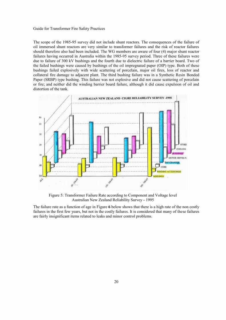
Guide for Transformer Fire Safety Practices
20
The scope of the 1985-95 survey did not include shunt reactors. The consequences of the failure ofoil immersed shunt reactors are very similar to transformer failures and the risk of reactor failuresshould therefore also had been included. The WG members are aware of four (4) major shunt reactorfailures having occurred in Australia within the 1985-95 survey period. Three of these failures weredue to failure of 300 kV bushings and the fourth due to dielectric failure of a barrier board. Two ofthe failed bushings were caused by bushings of the oil impregnated paper (OIP) type. Both of thesebushings failed explosively with wide scattering of porcelain, major oil fires, loss of reactor andcollateral fire damage to adjacent plant. The third bushing failure was in a Synthetic Resin BondedPaper (SRBP) type bushing. This failure was not explosive and did not cause scattering of porcelainor fire; and neither did the winding barrier board failure, although it did cause expulsion of oil anddistortion of the tank.
Figure 5: Transformer Failure Rate according to Component and Voltage levelAustralian New Zealand Reliability Survey - 1995
The failure rate as a function of age in Figure 6 below shows that there is a high rate of the non costlyfailures in the first few years, but not in the costly failures. It is considered that many of these failuresare fairly insignificant items related to leaks and minor control problems.

Guide for Transformer Fire Safety Practices
21
Figure 6: Yearly Failure rate according to ageAustralian New Zealand Reliability Survey - 1995
It is often assumed that the failure rate follows a “bath tub curve” where failure rates are higher in thefirst few year of service, followed by a lower failure rate for many years thereafter and then rising toa higher failure rate towards the end of the transformer’s service life.
The data on failure rates from the Australian / New Zealand transformer survey indicates that there isan increased risk of failure in the first few years of service, but it does not support the intuitiveassumption that failure rate will increase towards the end of a transformer’s in service life. The sametrend is also evident in data from other transformer failure surveys.
It is not clear why this is so, but it could be due the fact that many utilities retire a high proportion oftheir older transformers before they fail and the remaining population of older transformer may be inas good or perhaps better condition than the average transformers of lesser age.
3.1.3 Surveys on Major Transformer Failures by ManufacturerOne of the major manufacturers reported the following failures of transformers rated above 100MVAat an Australian New Zealand transformer panel meeting in 2004 based on repairs and investigationsthey have carried out over the preceding five years on transformers owned by Australian utilities [25]
Twenty two (22) major failures (excluding fires) caused total loss or necessitating majorrepairs.
Eighteen (18) transformers suffered damage with repair costing in excess of 50 % of newreplacement cost. The manufacturer considers that these failures represents approx 70 % ofall Australian transformer failures for transformers rated >100 MVA. Based on estimatedpopulation over the time of these failures, the rate of serious failures would be approx. 1.0 %per transformer year.
The failure rate for major failures found in this survey is therefore 2.5 times higher than reported forcostly failures in the 1985-95 survey. The causes for this increase are not evident from the survey.

Guide for Transformer Fire Safety Practices
22
However, based on observations of practising utility engineers the following changes have occurredbetween the two surveys:
OIP bushings are now more common than they were in the 1975-1995 transformerpopulation.
Plant utilisation - (average loading) has increased.
Utilities are more prepared to overload transformers now than in the past.
The amount of maintenance has reduced and the number of maintenance technicians andtheir skill level in primary plant maintenance has reduced due to lesser degree ofspecialization.
The average consumer has experienced an increased in loss of supply events and an increasein duration taken to restore supply.
3.1.4 CIGRE Australia 2002 Survey on Major Transformer Failures and FiresA survey on transformer fires also was CIGRÉ Australia – New Zealand transformer panel APA2.This survey was carried by out in late 2002 covering the five-year period 1997-2002. Replies werereceived from six (6) utilities. This survey did not include any generator utilities, but included allAustralian and New Zealand transmission utilities and approximately 2/3 of the sub-transmission/distribution utilities, which participated in the 1985-95 survey. This survey wastherefore based on a smaller transformer population than the 1985-95 survey (approx. 1800 vs. 3000).The number of transformer fires recorded from 1997 to 2004 was 11 fires over seven years. Theaverage transformer population covered by this survey is estimated to be approx 1800 transformersfor seven years = 12600 transformer service years, resulting in a major oil fire risk of 0.09 % pertransformer service year. This figure, whilst still low, is 9 times higher than the figure from the 1985-95 survey. Anecdotal evidence supports the finding that transformer fires are now more common,even when allowing for possible under reporting in the 1985-95 survey.In this survey 10 of the eleven fires was caused by explosive failures in HV bushings or in cableterminations within a cable box. The last fire was caused by a failure within an OLTC. No fires werecaused by failures within windings or other in tank components.
3.1.5 Transformer Failure Rate Russia and UkraineA paper presented by the late V.Sokolov et.al [26] provides very comprehensive data on transformerfailure rates and causes of transformer failures. The data presenting in that paper include more than500 transformers and the time periods from 1955 up to 2005.
The failure rates reported in that paper varies for different voltage classes and types of transformersbut most of the failure rates 0.5 at 1.5 % /year with an average failure rate in the order ofapproximately 1% /year. With the exception of the year 1-3 where failure rates tend to be higher(infant mortality) the failure rates are otherwise fairly constant with a slight increase at about midlife19-21 years old and the reduced failure rates for older transformers of the 220/110 kV and the500/220 kV voltage classes, which is similar to the failure rates reported in the Australian/ NewZealand survey. This survey does not provide any information of the incidence of transformer fires.
3.1.6 Power Transformer Fire Risk Assessment by a Major Canadian UtilityA significant contribution in for development of quantitative data for transformer failures, tankrupture and fire incidence was made by [27] in 2008. The following information and tables are from[27].

Guide for Transformer Fire Safety Practices
23
Table 3 : Statistics by a major Canadian Utility 1965 -1985: Fire rate
Voltage Class [kV] Failure rate/year(%)
Fire incidencein % of failures
Fire incident rate/year (%)
735 (Transformers) 2.32 9.5 0.22735 (Reactors) 3.15 11.4 0.36
315 0.84 21,9 0.18230 0.49 15.8 0.08161 0.50 0 0.00120 0.6 2.6 0.02
Average 1.21 8.38 0.14
From the data presented in Table 3we can conclude that the average failure rate is 1.2%, but thefailure and fire incidence rates for the 735 kV class is much higher than for all other voltage classes.The average fire incidence is 8.4% of all failures and the average fire incidence rate per year is0.14%.
Table 4 : Statistics by a major Canadian Utility 1965 -1985: Explosion vs. Fire
Voltage Class [kV] Explosions Major oil spill Fires
735 15 9 8315 3 2 1230 2 1 1161 0 0 0120 5 3 3
Total 25 15 13
From the data presented in Table 4 we can conclude that a high percentage [75%] of explosivefailures (tank rupture) causes major oil spills and if there is an oil spill then there is also a high risk ofa transformer fire.
Table 5 : Statistics by a major Canadian Utility 1965 -1985: Fault Location vs. Fire Rate
Fault location Explosion Fire Fire rate %Bushings 25 11 44HV lead to tank 15 9 60HV Lead to bushing turret 8 4 50Within windings 21 0 00OLTC, Core and others 9 0 00
From the data presented in Table 5 we can conclude that when a bushing, a HV lead to tank or abushing and bushing turrets failure occurs [bushing line leads], then there is a very high risk ofexplosive failure and fire. These types of failures caused all of the above listed fires. It is interestingto note that winding, core, OLTC’s and “other failures did not cause any of the fires. This isconsistent with the findings from the Australian surveys except it had a single fire caused by andOLTC failure. The WG A2.33 is aware of other OLTC failures which have caused fires, but most ofthese have been minor fires involving ruptures of the OLTC diverter switch and OLTC conservatoroil only.

Guide for Transformer Fire Safety Practices
24
Table 6 : Arc Energy versus Consequences (735 kV Transformers and Reactors)
Arc Energy (MJ) Tank Ruptured Resulted in a Fire1.0 No No2.5 No No4.0 No No6.0 No No8.0 Yes No
Between 8.5 and 13 Yes Yes14 Yes Yes
Between 19 and 23 Yes No20 Yes No
Between 26 and 67 Yes Yes94 Yes Yes147 Yes No
From the data presented in Table 6, it is evident that there is a strong correlation between the arcenergy, tank rupture and transformer fire. This is of course what could be expected, however it isperhaps more surprising that it is possible to have a high arc energy rupture of a transformer tank andwithout a fire erupting. It appears that this scenario can occur where the arcing occurs in the lowerpart of the tank and the arc has been interrupted by the protection before the arc is exposed to air.
3.1.7 Transformer Failure and Fire Risk Rate in JapanThe transformer major failure and fire risk rate in Japan is relatively low compared to the othercountries.
The major failure rate (transformers which require replacement or repair) in Japan during1998 to 2001 = 0.054% per annum (p.a.).
The probability of transformer fire in Japan during 1991 to 2001 was only = 0.00012% p.a.
Since Japanese utilities have had a 500kV-1000/3MVA auto-transformer failure and fire in 1972, thequality of power transformer and manufacturing process has been improved, based on theinformation obtained during study in Japan conducted by the Electric Technology ResearchAssociation (ETRA). This joint study among the Academy, utilities and manufacturing in Japan werealso let to the introduction of counter measures to improve explosion withstand capability fortransformer enclosure. The counter measures included, reinforcement of transformer enclosures andpressure dispersion by enlarging the area between the main enclosure and the conservator. In additionto these activities, ETRA has still been conducting other countermeasures, such as diagnosis and LTCmaintenance, to improve transformer’s reliability.
The key factor in achieving the high reliability in Japan is the collaboration with utilities andmanufactures. Whenever transformer failures occur in Japan, Japanese utilities carry out failureinvestigations jointly with the manufactures, and repair others transformers of same design in thefield where needed this deemed to be required, the remedial action are also reflected into the designof new transformers.

Guide for Transformer Fire Safety Practices
25
As regard to diagnosis, Japanese utilities have done DGA since early 1970’s, and if DGA test hasfound deterioration in a transformer, then this transformer will be replaced so not to cause a failure.The criteria or interpretation of DGA results in Japan is stricter than that of IEC.
Coordination with high-reliability & high-speed protection relays has also been improved to increasereliability. In order to ensure that the transformer protection system functions correctly and clears thefault in the minimum duration, older types of protection relays were replaced with the latest onesusing the most modern digital technology. And the trip coils on circuit breaker are duplicated and aproportional differential relay and a high-speed over current relay are connected to the trip coilsrespectively to protect the transformer. In addition, the impedance of the transformer is specifiedslightly higher in transformers for indoor installation than for outdoor installations in order to reducethe fault current, taking the fault current and performance of the protection relays into consideration.
As regard to the transformer design, the tank of Japanese transformer is sealed with nitrogen gas toprevent oil degradation.
These are the main issues related to the reliability and design technology in Japan.
3.1.8 Insurance Company ExperienceA large insurer, who insures a fleet of over 100,000 transformers in six continents, in the period from2000 –2010, experienced a total of 594 transformer failures representing a loss of $650 million. Ofthese incidents, only 156 transformer failures, or about 25% of the total incidents resulted in fire.The incident of fires to failure reported here is higher than reported by most utilities a possibleexplanation could be that only the most serious failures are reported to insurers.
3.1.9 Transformer Failure and Fire Risk Rate - Data Other SourcesThe rates of transformer failures and the probability of transformer fires were also assessed frominformation provided in discussions at WG 2.33 meetings which has member’s representatives fromseveral major utilities.
Table 7 : Transformer Failure and Fire Risk Rate - Data Other Sources
UtilityTransformerpopulation(approx)
Rate of SeriousFailures(%p.a.)
Rate ofTransformer Fires
(%p.a.).
GermanyNational Statistics 0.6
0.06(Anecdotal - 10 % of
Serious Failures)RTE, France 1300 0.6 0.05
Eskom, SA 600 - 0.16
National Grid, UK 780 0.3 0.015
Swedish State Power BoardTransmission 1300 - 0.02
(3 fires in 10 Years)
Swedish State Power BoardHydro stations 100 - < 0.05
(no fire in 20-30 years)
Japan (1991-2001) 0.054 0.00012

Guide for Transformer Fire Safety Practices
26
3.2 Major Causes of Transformer Fire
3.2.1 Transformer Fire Initiated by Bushings and Cable Termination FailuresThere is clear evidence that transformers using Oil Impregnated Paper [OIP] bushings or cablesterminated in an air- or oil insulated cable boxes have an increased risk of fire following a bushing orcable termination failure. In the Australian New Zealand transformer fire survey it was found that 91% of transformer fires originated from an OIP bushing or a cable termination failure, with bushingand cable termination each accounting for 5 fires out of a total of 11 transformer fires (91%) and theremaining 9 % from one OLTC failure.
The failure from a major Canadian Utility data listed in Table 5 above included 24 transformer fires,46 % of these fires was caused by failure in OIP bushings and 54 % of fires from failure withinbushing turrets or from HV line leads to tank wall arcing failures, causing rupture of bushingturret/tank or breakage of bolted flanges. The latter mode of failure is prevalent in very high Voltage(735 kV), high fault energy failures. It is evident that HV bushing and HV bushing lead failures arethe two highest fire risk items on a transformer.
3.2.2 OIP Bushing Initiated FiresWhen an arcing failure occurs within the porcelain shell of an OIP bushing, it frequently results in anexplosive failure of the upper or the lower porcelain shell. (Refer to Chapter 2.2.3 for bushing failureinitiated fire scenario).
Working Group A2.33 members are not aware of any oil fires having been initiated by a failure in aRIP or SRBP bushing. However, this is not a categorical statement that a fire could not initiated bysuch bushing, but merely that the risk is much less than for OIP bushings. (Refer to Section 2.2.4 forcable termination failure initiated fire scenario).
3.2.3 Fires Initiated by Cable Termination FailuresCable terminations failures of often causes a transformer fire which can develop into a major firewhere an oil filled cable box is connected to the main tank or the conservator and the oil from themain tan tank or the conservator feeds the fire, which then can burn gasket on inspection and accesscovers and cause a major spill of oil from the main tank. (Refer to Chapter 2.2.3 for bushing firemethodology).
3.2.4 Fires Initiated by OLTC FailuresOLTCs failures is the cause of 10 -15% of fires, however these fires are often minor fires as thevolume of oil exposed to air is only a few hundred litres at the most, unless there has been a ruptureof the barrier between the main tank and the OLTC diverter/arcing contact oil compartment. Arcingfailure within the diverter switch or a combined selector switch will in most cases cause rupture ofthe recessed disc in the OLTC cover or activate the resealable pressure relief device, if the arc energyis relatively low, as it may be if the tapping winding is at the neutral end. A low arc energy fault mayonly initiate a small oil fire, as the oil surface exposed in the OLTC and the amount of oil in theOLTC conservator relative small. If the fault cleared quickly by the protection before the fireescalates, then it may or may not developed into a major oil fire. However, if the arc energy is high itis more likely that the OLTC cover or its tank may rupture and the barrier board to the main tank maybe broken. If this occurs then the oil will spill from the main tank, the conservator and the fire willquickly cover a much bigger surface and be fed by much larger oil volume.

Guide for Transformer Fire Safety Practices
27
3.2.5 Fires Initiated by a Tank RuptureOil fires originating from rupture of transformer tanks is rare for voltages below 300 kV, but is lessrare for voltages above 300 kV where the combination of longer flash over arc and higher systemfault levels often have enough arc energy to cause rapid and very high pressure increase and ruptureof the tank or bushing turrets, before the electrical protection have time to operate and interrupt thefault current.
If a rupture of the tank occurs whilst the arc is present, then there is a very high probability that it willignite the hydrogen and other hydrocarbon gases generated by the arc and also the oil spilling fromthe tank, resulting in a major oil fire.
It is reported in [27] that 13 of 24 fires (54 %) caused by rupture of tank and bushing turrets(chimneys), 4 of these where HV lead to bushing turret faults and 9 where HV lead to tank faults, allfaults causing a fire had very high fault energies (calculated to be > 13 MJ).
It is interesting and important to note that the author of [27] also reported that there were 21explosive failure caused by failures within windings and 9 explosive failures caused by faults incores, OLTC and other parts in the same period , but none of these explosive failures caused fires.
These findings are supported by [25] which also reported that none of the 11 fires reported in theAustralian New Zealand survey were caused by faults within windings.
Tank flexibility together with pressure withstand capability is an important factor when consideringwithstand against tank rupture and may be more important than pressure relief devices in reducingthe risk of tank rupture. This becomes evident when considering the significant increase in volumewhich can be accommodated in standard tank for only small pressure increases.
One of the WG A2.33 members has performed oil volume expansion/pressure test on a 350 MVAtransformer with an oil volume of 60 000 litres. The volume expansion was 600 litres for a pressureincrease from 0.45 to 1.45 bar measures at base of tank. The rupture withstand of this tank was notdetermined, but it is unlikely that it would have been less than 2 Bars measured at base of tank. Byextrapolation it can be concluded that this tank could accommodate at least a volume expansion of1000 litres at 2 bars at base of tank. This volume expansion capacity is very significant whencompared the amount of oil which could be discharged from a conventional PRV with 127mm dia.opening in say 50- 60 ms (typical breaker clearing). Much larger volume expansion could have beenachieved, if maximising volume expansion had been considered in the design criteria for the tankdesign criteria. Tank flexibility (volume expansion) as function of pressure increase is an importantfactor when evaluating tank rupture withstands capability. The indications from the test determininggas volumes vs. arcing energy is that the tank used in this test could withstand an arc energy in theorder of 10+ MJ before rupturing, unless the rupture were caused by fast acting localised pressurebuild-up.
3.3 The Probability of Transformer Fires - SummaryFrom the data presented in this chapter it can be concluded that the probability of major transformerfailure, which requires major repairs or scrapping of the transformer varies from about 0.5 to 2.5 %per transformer service year, with the average being approximately 1%.
A few utilities have significantly higher or lower failure rates, but they are exceptions. The majorityof utilities have close to the average rate, with some variations depending on the type and servicecondition of the transformer, the maker, the user’s procurement and maintenance practices. Thefailure rates tend to be higher for auto transformers, generator step up transformers and transformers

Guide for Transformer Fire Safety Practices
28
with On Load Tap Changers [OLTC], whereas two winding transformers in the 11- 300 kV tend tohave failure rates lower than the average failure rate.
The percentage of transformer failures resulting in a transformer fire is typically in the order of 5 to15 % of serious transformer failures, with an average probability of approximately 10 % of all seriousfailures.
This is a useful figure for utilities to have for calculating the approximate probability of transformerfires for their particular situation, as they can determine what risk they have of serious transformerfailure and the use the figure of 10 % of the failures resulting in a transformer fire.
From the above it can be concluded that the probability of a transformer fire is in the range of 0.04 -0.25 %/year, with the average probability of a transformer fire being approximately 0.1% /year(=1/1000 p.a.).
This represents an accumulated probability range 1.6-10 % per transformer and an averageprobability of 4% over a 40 years’ service life for the average utility owned transformer.
Transformer fires are therefore a low, but not a negligible risk. A four step approach forestimating the probability (risk) of a transformer fire is proposed below:
Step 1Utilities can improve the accuracy of their risk estimate for their transformer population and evenspecific transformers firstly by determining the failure rates they have in their transformer populationand then look at the specific transformer.
Step 2Is it a type of transformer, or a voltage class which have a higher or lower than average probability?If it is, then make the appropriate adjust to determine the risk of failure of this type or class oftransformer.
Step 3Use the revised “average” probability of a failure resulting in a fire from Step 2 and then determinewhat risk mitigating factors have been implemented on this specific transformer to reduce theprobability of fire further (RIP bushings; no cable box; condition of transformer etc.) and thendetermine what fire risk factor should be used to determine the risk applicable for the specifictransformer. Sufficient to say at this point that they include, the protection and circuit breakeroperating time, tank flexibility and tanks strength, pressure mitigation / depressurisation factor, typeof bushing, cable termination. The effect of risk minimisation measures will discussed further in theremainder of this document
Step 4
The probability of a transformer fire can then be determined as follows:[The probability of serious failure] x [The probability of a failure causing fire] x [Risk reductionmeasures K1, x K2, x K3.x..... Kn]
ExampleProbability of a transformer fire = 0.01x 0.1x [K1 x K2 x K3 x Kn] /year

Guide for Transformer Fire Safety Practices
29
3.4 The Risk to Potential Fire Victims – Other Substation AssetsWhen considering the probability and potential consequences of a transformer fire it is often usefulto categorise substations into types of substations as the specific strategies which can and should beapplied for fire risk management varies between types of Installation:
Open air substation where land cost is low: - space separation will often be most economicrisk management strategy.
Compact air insulation substations where land cost is high: In such installations fire barriersin form of reinforced concrete panels/wall, sound/fire enclosures, or water spray “curtain” iscommon forms of fire protection in such installation.
Under ground or city building substation: Such installation will normally have a very sitespecific and fire prevention and fire contingency management strategies. Japan has welldeveloped designs for risk management in such installation, using a combination fast actingprotection, large duct opening between the banks and to the conservator and high strengthtanks design, to allow oil to move reduce rate of pressure rise and contain the oil and arcinggases without rupture of the tank. If the installation is in the basement of an occupied officebuilding or people traffic area then SF6 cooled transformers will probably be the safestoption [Such transformer can be made virtually free of fire risk].
Power station unit and generator step-up transformers: Deluge or fogging water spraysystem can be effective in protection the other power station assets, as reliable and highcapacity water supply is usually readily available at most power stations. It is important toconsider that water spray may also be required to cool nearby building structure or othercritical assets, not just the fire origin – the transformer.
Other types of installation – Installation which does not lend itself to be categorised must beconsidered on a one by one basis.
Other common precautions which apply to all installations and should be considered include:
Oil containment - spilling of oil outside the substation during a fire is not considered anaccident, but negligence and a failure to foresee and manage the risk. However, the Oilcontainment system should be fit for the specific site conditions.
Oil spilled from the fire source (one transformer) should not be able to travel along cabletrenches or conduit or other means where it can potentially spread the fire to building or otherplant items.
Most utilities have well developed oil containment systems to suit their specificrequirements. Key requirements are that oil should be directed rapidly away from the firezone so it is not available to fuel the fire and not contaminate the environment. The oilcontainment system must be fit for the climatic and other site specific conditions.Underground oil/water separation tank is becoming widely used in Australia and some other.This system will separate transformer oil mixed with water to less than 10ppm oil in thewater at the outlet from the from oil separation at max flow rate through the separation tank.A Canadian utility [28] uses a mat/membrane system suitable for cold climate, which allowswater to flow through, but will contain oil and prevent it from contaminating the groundwater.
Emergency plans which include clearly defined responsibilities, delegated authorities and arange of pre-considered contingencies and “what if” scenarios and drill practice plans.

Guide for Transformer Fire Safety Practices
30
Access to key areas of the substation with anyone transformer on fire. Multiple access pointmay be necessary.
Radiated or wind borne heat should not be able to initiate fire in other substation assets.
Fire brigade access, availability of water/foam/other fire suppressants for fire fighting. Whilstwater is generally not effective in extinguishing transformer oil fires and foam not effectivein fighting oil fires with oil spilling over vertical surfaces, water can be very effective incooling the fire to reduce heat output and also in prevent fire spreading to adjacent assets andfoam and water can be very effective in extinguish pool fires.
The above points will be discussed further in the remainder of this document.

Guide for Transformer Fire Safety Practices
31
Chapter 4: Internal Arcing and Tank Ruptures
4.1 Arc EnergyThe oil vaporisation process is linked to the arc energy but not directly to the transformer power.Moreover, the arc energy depends on the transformer location in the grid, which drives the maximumavailable arc current.
Arc energy E (Joule, J) is then a function of arc current Iarc (Amperes, A) voltage Varc (Volt, V) andduration tarc (seconds, sec) as shown by the following formula:
arct
arcarc dttItVE0
)()( Equation 1
Arc current: In the survey undertaken by the authors seems to show that the most probablerange for an arc current will be between 10 kA and 30 kA with a probabilistic peak between10 kA and 20 kA.
Arc duration: It seems that the most probable range is 3 to 4 cycles for a 50-60Hz current.Arc current can in most cases easily be evaluated by the short-circuit levels, as well as theduration by the type of protection (relay and breaker);
Arc voltage: Difficulties arise in the evaluation of arc voltage. Most of the time online directmeasurements are not available to assess this parameter.
A simple correlation between the arc length and the arc voltage [29] is shown in Figure 7.Nevertheless it remains difficult to estimate a priori the arc length as the pressure and temperature atthe arc is unknown.
Figure 7: Arc voltage as a function of arc length [29]
One utility have been able to carry out this type of measurements using high precision inductive PT´sinstalled on their 735-kV systems. In a typical recording Figure 8, voltage is shown to reachsignificant values (more than 40 kV) during the first instants after ignition. The fault current is inmost cases known from the known fault level of the substation or from fault event recorders, sowhere volt current and fault duration is known.

Guide for Transformer Fire Safety Practices
32
a) Arc voltage (kV) from different PT
b) Arc currents for HV (red) and LV (green) sides
Figure 8: Example of arc energy calculation (8 MJ) based on actual fault voltageand current measurements.
The peak arc voltage values observed cannot be explained by only an effective arc length longer thanthe insulation distance. Some other phenomena need to be involved, one of them being the possibleeffect of pressure on the voltage. In [30] and [31] for example the authors propose another correlationbetween the arc voltage and the arc length that tries to model the gas bubble pressure influence:
PLVarc 55 Equation 2
with:
55 : empirical constant (V/cm) Varc : arc voltage (Volt, V) L : arc length (cm) P: absolute pressure in the gas bubble surrounding the arc (Atm)
At arc ignition and the few following ms, vaporization process results in high local overpressures, theinfluence of this pressure peak might explain the unexpected arc voltage measurements displayed inFigure 8. The fault current is in most cases known from failure event recordings or known fault level,so if the arc voltage and arc duration can be established then it becomes possible to calculate the arcenergy through Equation 1.
Unité Support et analyses - DESTT
205 210 215 220 225 230 235 240 245 250 255(ms rel. à 05:34:32.2870)
-80
-60
-40
-20
0
20
40
60
80
100
(kV)
E BN TT MAIS MICOUAE BN L-7019 MICOUAE BN L-7011 MICOUAE BN L-7027 MICOUA
2008-09-12 05:34:32.499 MICOUA 735-02 TENSION RÉSIDUELLE DÉFAUT TRANSFO T8-B
205 210 215 220 225 230 235 240 245 250 255(ms rel. à 05:34:32.2870)
-1 0 1 2 3 4 5 6 7 8 9
101112
(MJoules)
ÉNTERGIE TOTALE (TT MAIS)ÉNTERGIE TOTALE (TTC 7019)ÉNTERGIE TOTALE (TTC 7011)ÉNTERGIE TOTALE (TTC 7027)
2008-09-12 05:34:32.499 MICOUA 735-02 ESTIMÉ DE L'ÉNERGIE TOTALE DANS LE DÉFAUT TRANSFO T8-B
190 200 210 220 230 240 250 260 270(ms rel. à 05:34:32.2870)
-20000
-15000
-10000
-5000
0
5000
10000
15000
20000
(A)
COURANTS CÔTÉ 735 kVCOURANTS APROX. CÔTÉ 315 kV
2008-09-12 05:34:32.499 MICOUA 735-02 COURANTS DE DÉFAUT TRANSFO T8-B
Lundi 15 Septembre, 2008\\VECTEUR\DONNEES\PARTAGE\@AUTOMATISMES\COMPORTEMENT\RAPPORT\RAPP_2008\TOSC_ANA\20080912_053432499_ENERGIE_T8-B_MICOUA.TOS
PT1 (Inductive)PT2 (Capacitive)PT3 (Capacitive)PT4 (Capacitive)

Guide for Transformer Fire Safety Practices
33
4.2 Gas GenerationThe volume of gas generated by an arc in oil has been mainly investigated for the application of oilcircuit breakers. One of the first reported studies on that matter was published in 1953 [31]. Thisinvestigation established an approximate arc energy dissipation breakdown as follows:
13.8% Energy loss at contacts11.8% Energy radiated from arc column4.0% Energy to heat oil to its boiling point14.5% Energy to breakdown the oil into gas34.6% Energy to heat gas at constant volume10.2% Energy to cause expansion of gas formed10.2% Energy used to dissociate the hydrogen formed
Average gas volume generation was found to 70 cc (Standard Temperature and Pressure) per kJ ofarc energy with a composition of about 70 % H2, 25 % C2H2 and 5 % other hydrocarbons (CH4 andC2H4). The report also includes a discussion on arc and surrounding gas temperature. Valuesmentioned for the reaction zone ranged from 1700K to 3500K with a suggested average of 2000K.Values of gas generation rate reported by a number of other investigators are quite similar, see Table8 below:
Table 8 : Measured Gas Generation Rate
Reference Year published Gas volume (STP)generated (cc/kJ)
Trencham [31] 1953 70Castonguay [32] 1975 61Goto et Miura [33] 1987 50-70Cuk [34] 1990 85Darian et al. [35]
1 V.P. Efremov etal. “PhysicalInvestigation andExplosions Simulationof Oil-FilledTransformers”, CIGRÉInternationalColloquium onTransformer Researchand Asset Management,Cavtat, Croatia,November 12-14th,2009.
2009 110
All the authors mentioned above concluded that the gas generation rate can be represented by linearfunction with arc energy, and found evidence that an average gas formation temperature of about2000 °K is a reasonable assumption. There was also good agreement on the gas composition betweenthe different investigations.
The linear relationships proposed yielded an energy transfer factor from the arc to the gas bubble inthe range of 15 % to 40 %. Gas generation rate has been observed to show a stochastic behaviour[34], [36] for that reason a value of 100 cc/kJ (STP) has been used by several investigators as aconservative assumption in the 20 to 2640 kJ arc energy range.

Guide for Transformer Fire Safety Practices
34
Figure 9: Comparison of gas generation models and experiments from different authors(Gas volume at Normal Pressure and 2000 K)
4.3 Pressure Calculation Models
4.3.1 Simplified Containment ModelPressure build-up following an arc inside a transformer depends on the volume of gas generated bythe arc and the tank expansion characteristics. A simplified expression was first proposed by [37]; itis based on the conservative assumption of an isothermal expansion of the gas bubble. Equation 3andFigure 10 from [38] present a modified version which includes different arc parameters and a moreelaborate dynamic amplification factor than the single value suggested in [37].\
Equation 3
Where:
Ps: calculated tank pressure [kPa above atmospheric] E: fault energy level (kJ) k: arc energy conversion factor (= 5.8 x 10⁻⁴ m3/kJ) [@2000 oK] C: tank expansion coefficient (m3/kPa) F: dynamic amplification factor given in Figure 10. V: volume of oil in main tank (m3).
1.00
10.00
100.00
1000.00
10000.00
10 100 1000 10000 100000
Gas
Vol
ume
(l) N
orm
al P
ress
ure
Arc Energy (kJ)
Kawamura
Castonguay
Trencham (70 STP cc/kJ)
Darian et al. (110 STP cc/kJ)
50
10041100
CkEFPs

Guide for Transformer Fire Safety Practices
35
Factor k is based on internal experiments which suggest a gas generation rate of 85 cc/kJ and anaverage temperature of 2000 K. This represents about 24 % of arc energy transferred into enthalpy(available expansion energy) of the gas bubble.
Figure 10: Variation of the dynamic amplification factor F for Equation 3
F is a factor which indicates the ratio of the localised dynamic pressure and the static pressure fromdeveloped from an internal arcing fault. Extensive numerical and experimental (high-speed gasinjection) simulations have shown that local pressure and, more specifically, deformation exhibit adynamic amplification factor that is best expressed as a function of the ratio of tank flexibility overoil volume (C/V).
4.3.2 Simplified Venting ModelIn a model proposed by [39], the tank is divided into the several tank elements in the calculation asshown in Figure 11. The pressure rise in each element at the internal fault is calculated by thedynamic analysis considering oil motion (inertia and pressure losses).
Figure 11: Simplified numerical model for venting to adjacent tanks
Pressures can then obtained by solving numerically a set of equations relating the pressure of thedifferent elements with velocities in the pipes. This model proved to be useful in the evaluation ofventing pipes and pressure reduction spaces.
1
1,5
2
2,5
3
0 20 40 60 80 100 120 140 160 180 200
C/V (x 10 -5 kPa-1)
F
Element i Element i+1
Pressure Pi Pi+1
Ui-1 Fluid Displacement Ui Ui+1
Pipe i-1
Connecting Pipe between EachTank Element
Pipe i Pipe i+1
Element i Element i+1
Pressure Pi Pi+1
Ui-1 Fluid Displacement Ui Ui+1
Pipe i-1
Connecting Pipe between EachTank Element
Pipe i Pipe i+1
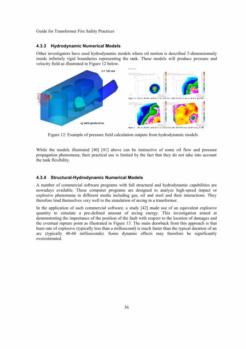
Guide for Transformer Fire Safety Practices
36
4.3.3 Hydrodynamic Numerical ModelsOther investigators have used hydrodynamic models where oil motion is described 3-dimensionnalyinside infinitely rigid boundaries representing the tank. These models will produce pressure andvelocity field as illustrated in Figure 12 below.
Figure 12: Example of pressure field calculation outputs from hydrodynamic models
While the models illustrated [40] [41] above can be instructive of some oil flow and pressurepropagation phenomena; their practical use is limited by the fact that they do not take into accountthe tank flexibility.
4.3.4 Structural-Hydrodynamic Numerical ModelsA number of commercial software programs with full structural and hydrodynamic capabilities arenowadays available. These computer programs are designed to analyze high-speed impact orexplosive phenomena in different media including gas, oil and steel and their interactions. Theytherefore lend themselves very well to the simulation of arcing in a transformer.
In the application of such commercial software, a study [42] made use of an equivalent explosivequantity to simulate a pre-defined amount of arcing energy. This investigation aimed atdemonstrating the importance of the position of the fault with respect to the location of damages andthe eventual rupture point as illustrated in Figure 13. The main drawback from this approach is thatburn rate of explosive (typically less than a millisecond) is much faster than the typical duration of anarc (typically 40-60 milliseconds). Some dynamic effects may therefore be significantlyoverestimated.

Guide for Transformer Fire Safety Practices
37
Figure 13: Example of stress field outputs from an explosive simulation of the arc
In reference [43] a methodology to simulate the effects of an arc by the injection of a given quantityof gas with properties such as detailed in is described. The resulting model has been used toinvestigate real failure cases such as shown in Figure 14. This model, also based on commercialsoftware, includes the complete set of equations and therefore simulates all relevant phenomena suchas: oil compressibility, pressure wave propagation, elastic-plastic deformation of the tank, gas-oil-tank interactions, etc. These features however require important modelling and computationalresources.
Figure 14: Example of a real chimney rupture case with an arc simulation methodology
4.4 Pressure ContainmentIn general transformer tanks are designed to withstand an internal operating pressure ofapproximately 50-100 kPa (relative to Atmospheric and above head of oil), and to withstand full

Guide for Transformer Fire Safety Practices
38
vacuum without plastic deformation. Therefore the ultimate rupture pressure can be evaluatedsomewhat above 150-200 kPa. It is the working groups experience that tanks for large HVtransformers >100 MVA, typically have flexibility in the range of 0.5 -1.5 % volume expansion per100 kPa pressure increase.
Tanks with withstand pressure and typical volume expansion as listed above; can be expected to havearc energy containment within the range listed below.
Table 9 : Approximate range of arc energy containment capability ofthree phase transformer with conventional tank designs
Voltage (kV) Lower (MJ) Upper (MJ)
500 – 800 4.0 10.0
275 – 400 3.5 8.0
132 – 170 3.0 6.0
100 – 120 2.0 4.0
4.5 Pressure VentingUp to 1960-70, it was common practice to equip transformers with over pressure venting in form of a“gooseneck” shaped venting pipe (sometimes also called an explosion vent). The interface to the airon the pipe was usually sealed with a membrane designed to rupture at a pre-determined overpressure on the oil side of the membrane. In the last few decades it has become common practice formany transformer users to specify one or more spring loaded self re-sealing Pressure Relief Valve[PRV] instead of the “gooseneck type vent pipe”. Such PRV’s are available in a range of sizes. A 5inch (127 mm) opening diameter is a very common size and it is common practice fit one PRV fortransformer small and medium size transformer < 40000 litres of oil, and to use two or more PRV’svalves for large power transformers. Many users are fitting these types of PRVs to transformers in thebelief that they would prevent tank rupture in the event of internal arcing fault.
Upon field cases investigations it is often wrongfully assumed that a PRV which operated without atank rupture is a proof of performance. However, the venting capacity of such PRVs is completelyinadequate to provide sufficiently fast pressure relief to prevent tank rupture for a high energy arcingfault. At best they might have a material effect on pressure reduction for arcing fault close to theventing port, where the vented product is mainly arcing gases. For faults further away from theventing port where the vented product is mainly oil, the pressure reduction provided by one or two 5”PRVs are far less, than the contribution made by the elasticity/ volume expansion of the tank withinthe plastic deformation range. (Refer to Figure 15 and Figure 16).
PRVs do nevertheless have benefits insofar they act as a safety valve for over pressure when fillingtanks with oil and will provide pressure relief for residual pressures from and arcing fault where thefault have been cleared by protection prior to the tank ruptures. It is also considered they can makematerial impact on pressure reduction on hermetically sealed gas cushion transformers, where thevented product would be gases and the pressure build would be slower due to the compressibility ofthe gas cushion.
The question of determining the efficiency of venting devices in preventing tank rupture during amajor fault is quite complex and therefore cannot be based on anecdotal field evidence, but requiresextensive failure statistics of well documented forensic reports. Such data is, if any, is not easilyaccessible and the only alternative is to rely on theoretical and numerical investigations.

Guide for Transformer Fire Safety Practices
39
4.5.1 Theoretical Upper Bound AnalysisWhile a detailed calculation of the efficiency of pressure venting would require much effort, a simpleanalysis with only conservative assumptions can give an upper bound for the venting efficiency oftypical venting apertures. Hence, if we consider the following simplifying assumptions:
Venting discharge area is fully open immediately at arc ignition (no time delay for the valveto open or the disc to rupture)
Oil discharge velocity is the maximum theoretically possible immediately at arc ignition andit stays constant throughout the fault. An internal static pressure of 200 kPa is used tocalculate this discharge velocity (18.0 m/s).
Gas discharge velocity is the theoretical maximum for compressible gases (at choking).Based on a temperature of 2000K, this velocity is estimated to be less than 850 m/s.
There is no flow friction through the aperture Dynamic effects (oil inertia and arc location) are neglected. Peak pressures are therefore
assumed to coincide with arc extinction.
Then a simple formulation can be derived using equation presented previously (see also reference[44] for a detailed derivation) and the venting efficiency can be evaluated by comparing the ventedand non-vented calculated situations. Since this is an upper bound analysis, it is not easy to estimatethe difference with realistic venting efficiency values, it can only be stated that actual performancefrom any venting device should be considerably less than the values presented below.
In the following paragraphs, an example case is considered for illustration purposes, actualparameters were selected from a modern tank design, in order to represent a typical size powertransformer:
Rating: 100 MVA Height: :3m Width: 4m Depth: 2.5m Tank flexibility: K = 0,0066 m3/kPa
Firstly, if we consider the most favourable case for venting efficiency, i.e. when the arc is located inthe immediate vicinity of the venting aperture, or in a gas cushion transformers then the formulationis based on the maximum gas discharge velocity. Making the upper bound assumption that this gaswill discharge at a velocity of about 1000 m/s (corresponding to a gas bubble temperature of about2000 °K) then the maximum theoretical pressure reduction can be plotted as in Figure 15 below.

Guide for Transformer Fire Safety Practices
40
Figure 15: Upper bound for venting efficiency (% peak pressure reduction)Arc (3 cycles duration) located in the immediate vicinity of the aperture
It can be seen that pressure venting by PRV’s, rupture discs of or other form vent opening can have amaterial effect on the pressure reduction for faults close to the venting port where the main productvented is decomposition gases. A common size PRV with 127 mm dia. opening could achieve a 30 %venting efficiency for arcing energies up 6 MJ and a 200 mm dia. PRV could achieve up to 40 %venting efficiency for up to 6 MJ.
For arcing fault located even a short distance away from the venting port (say 1m or more) efficiencywill be reduced as the venting product will become essentially oil. The venting efficiency is far lesswhen the vented product is oil, as the discharge velocity is severely reduced by the material. This isillustrated in the next example in Figure 16 below.

Guide for Transformer Fire Safety Practices
41
Figure 16: Upper bound for venting efficiency (% pressure reduction)Arc (3 cycles duration) located more than 1 m from the aperture
While the analysis considers arc energies up to 20 MJ, the range of interest lies between 3 and 10 MJwhich are lower and upper bounds for rupture in a tank of this size. It can be seen that for the typicalpower transformer considered:
The required aperture diameter for a significant pressure reduction (30 %) should be at least100 cm for arc energies up to 3.5 MJ and 140 cm for arc energies up to 6 MJ.
The pressure reduction that can be expected from a 25 cm aperture is less than 3 % for arcenergies where tank rupture becomes a serious risk.
Tank rupture have been observed to rupture after fault of typically 3-4 cycles, but if we consider, forthe sake of this upper bound analysis, a 30 cycles arc duration, then the relative venting efficiencycan be shown to significantly increase as illustrated in Figure 17 below: However it should be clearlyunderstood that the reason the venting efficiency is increased is that an arc which produced the sameamount of acing energy over 30 cycles as another arc over 3 cycles has only 1/10th of the formersintensity.
0.0%
10.0%
20.0%
30.0%
40.0%
50.0%
60.0%
0.00 2.00 4.00 6.00 8.00 10.00 12.00 14.00 16.00 18.00 20.00
Peak
pre
ssur
e re
duct
ion
(%)
Arc Energy (MJ)
25 cm
60 cm
100 cm
140 cm

Guide for Transformer Fire Safety Practices
42
Figure 17: Upper bound for venting efficiency (% pressure reduction)Arc (30 cycles duration) not located within the immediate vicinity of the aperture
4.5.2 Venting SimulationThe theoretical evaluation above has been verified with simulation studies that have been carried outwith the advanced numerical tool described in [43]. The tank conditions were the same as the caseabove, arc energy was set to 10 MJ with a 50 ms duration. The model and more detailed simulationresults are also presented in reference [43]. In particular, the peak pressure reduction from a 25cmdiameter disc was confirmed to be well within the maximum of 3% calculated with the upper boundanalysis.
Other investigators have also presented simulations (experimental and theoretical) that led to verysimilar conclusions:
The first investigation by a Japanese consortium and summarized in [37] considered aconcept where the pressure is vented to adjacent tanks and the conservator. Calculationmodels and experiments on actual tanks (in which the arc was simulated by explosives) wereused to establish the pressure reduction achieved by different duct diameter. It was concludedthat a venting duct area of about 0.7 m2 would only yield a pressure reducing effect of 20 %.
The EPRI research team [44] analysed the same issue through numerical simulations. Thepressure reduction effect of a 1 m2 venting area was estimated to be less than 10% for a 20MJ arc with duration of 75 msec. This pressure reduction estimate was increased to about 15% if the same energy level was liberated during a 150 ms arcing fault.
At least one power transformer manufacturer has put forward some solutions making use ofventing through bursting discs. The modelling methods they used to design the ventingsystem are described in [45]. Based on their analysis, they came to the conclusion that a high
0,0%
10,0%
20,0%
30,0%
40,0%
50,0%
60,0%
0,00 2,00 4,00 6,00 8,00 10,00 12,00 14,00 16,00 18,00 20,00
Arc Energy (MJ)
Peak
pre
ssur
e re
duct
ion
(%)
25 cm
40 cm
60 cm
80 cm

Guide for Transformer Fire Safety Practices
43
number of bursting disc were required to cover local overpressure effects and providesufficient venting area. One such design made use of a total of more than 40 discs connectedto oil containment tanks such as illustrated in Figure 18 below.
Figure 18: Transformer equipped with a 40 rupture discs depressurization system

Guide for Transformer Fire Safety Practices
44
Chapter 5: Fire Risk and Performance Analysis
5.1 IntroductionThe aim of this chapter is to provide an overview of fire safety performance evaluation for atransformer as well as its installation.
Performance evaluations do not answer the question: Was a transformer designed andinstalled in accordance with applicable codes and standards?
Rather, it examines the questions: Will its protection layers perform the function for which itwas intended? When required?
The focus in performance evaluation is on understanding behaviour, not on regulatorycompliance.
5.2 Performance AnalysisThe prevailing assumption is that fire safety can be achieved through a combination of commonsense and the enforcement of regulatory practices, i.e. a prescriptive approach to fire safety.However, today’s transformer installations are rarely simple and unchanging. Their complexitiesrequire a more effective approach to fire safety, given the uncertainties surrounding its design,construction, operation and maintenance.
There is a tendency, particularly in the reports of public inquiries following a disaster, for a detailedrange of prescriptive measures to ensure this never happens again. Such prescriptive requirementshave met with success in reducing losses. There is no doubt that the use of standards of care, i.e. goodpractices, helps to reduce risks. But, they provide no means of measuring the level of safety of acomplex system such as a substation. Therefore, an effective approach to fire safety is needed to dealwith the complexities and changes that exist in substations. This chapter proposes that performanceanalysis recognize the multifaceted approach to safety so as to help engineers to provide effectivesafety.
Figure 19 provides an overview of performance analysis steps.
5.3 Understanding the Problem and Identifying System FeaturesThese two essential stages of the performance analysis identify how the transformer installationoperates and functions as well as the potential fire scenarios:
what is at risk (people, special property, function, neighbours and the environment);
what is important regarding potential fire losses;
and efficiently documents the important risk management information.
In other words, they describe the installation and its site features that influence fire safetyperformance and the associated risks.

Guide for Transformer Fire Safety Practices
45
Figure 19: Performance Fire Risk Management
The following questions aim to show how understanding the problem, Figure 20, can helporganizations to make appropriate decisions. Ignoring these issues during the life cycle of thetransformer and its installation can lead to inefficient safety process activities.
1. What are the organization’s goals? Should be non-controversial statements that aremeasured qualitatively, i.e. provide physical safety for workers and the general public.
2. What are the organization’s loss objectives? To support the above goals, i.e. no loss of lifeand no fire spreading beyond its source.
3. How will the organization achieve its loss objectives? By ensuring the integrity of thetransformer tank and its protection layers with proper design, inspection and maintenance.
4. What indicators will meet the organization’s goals and loss objectives? After stakeholders’goals and objectives have been established, the next step is the selection of performancecriteria. This criterion can take the form of damage indicators (i.e. a threshold values) orfollow applicable codes such as NFPA 101 or NFPA 810.The damage indicator utilizedshould come from technical documents and their selection should be thoroughly explained toand documented for stakeholders.
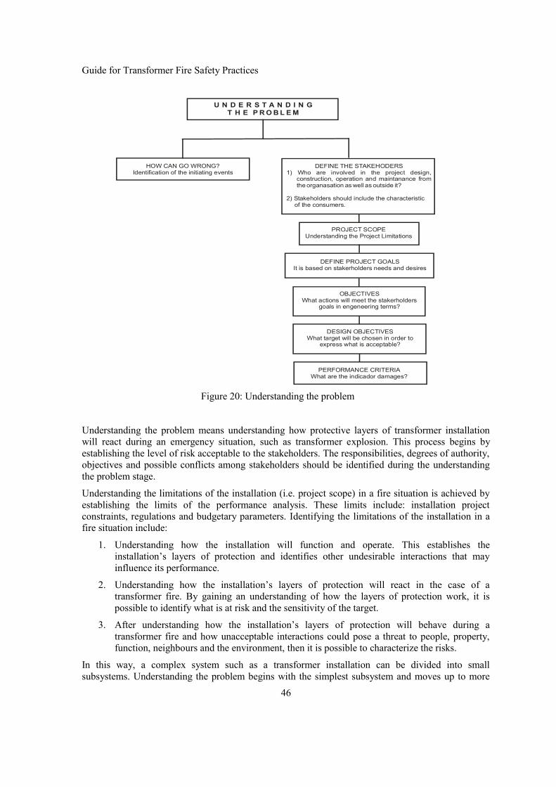
Guide for Transformer Fire Safety Practices
46
OBJECTIVESWhat actions will meet the stakerholders
goals in engeneering terms?
DESIGN OBJECTIVESWhat target will be chosen in order to
express what is acceptable?
PERFORMANCE CRITERIAWhat are the indicador damages?
U N D E R S T A N D I N GT H E P R O B L E M
DEFINE THE STAKEHODERS1) Who are involved in the project design,
construction, operation and maintanance fromthe organasation as well as outside it?
2) Stakeholders should include the characteristicof the consumers.
PROJECT SCOPEUnderstanding the Project Limitations
DEFINE PROJECT GOALSIt is based on stakerholders needs and desires
HOW CAN GO WRONG?Identification of the initiating events
Figure 20: Understanding the problem
Understanding the problem means understanding how protective layers of transformer installationwill react during an emergency situation, such as transformer explosion. This process begins byestablishing the level of risk acceptable to the stakeholders. The responsibilities, degrees of authority,objectives and possible conflicts among stakeholders should be identified during the understandingthe problem stage.
Understanding the limitations of the installation (i.e. project scope) in a fire situation is achieved byestablishing the limits of the performance analysis. These limits include: installation projectconstraints, regulations and budgetary parameters. Identifying the limitations of the installation in afire situation include:
1. Understanding how the installation will function and operate. This establishes theinstallation’s layers of protection and identifies other undesirable interactions that mayinfluence its performance.
2. Understanding how the installation’s layers of protection will react in the case of atransformer fire. By gaining an understanding of how the layers of protection work, it ispossible to identify what is at risk and the sensitivity of the target.
3. After understanding how the installation’s layers of protection will behave during atransformer fire and how unacceptable interactions could pose a threat to people, property,function, neighbours and the environment, then it is possible to characterize the risks.
In this way, a complex system such as a transformer installation can be divided into smallsubsystems. Understanding the problem begins with the simplest subsystem and moves up to more

Guide for Transformer Fire Safety Practices
47
complex ones. It is crucial to understand the details of each subsystem and their interactions and toproduce likelihood estimates. The consequences of transformer fire can thus be quantified.
5.4 Evaluating Performance and Risk CharacterizationThis section analyzes the expected extent of the transformer fire, smoke, and structural collapse. Afunctional performance analysis uses the previous information with other on-site observations andfire knowledge to analyze fire suppression. This analysis provides an understanding of expectedsystem or transformer fire conditions and the ease and likelihood of fire control and extinguishment.Expectations about the elapsed time to target spaces damage and structural collapse performance maybe estimated with greater confidence. Collectively, fire behaviour from ignition to extinguishment,the associated smoke conditions, and structural responses for the fire duration describe system fireperformance.
Performance evaluation goal is to understand the range of performance scenarios in order to paint alikely picture of the installation’s behaviour in the event of a transformer fire or explosion, Figure 21:Transformer Fire Performance. This understanding, combined with the information gathered in orderto understand the problem, provides the basis for characterizing the risks.
Transformer Fire Performance
Will a fire threat occur?
What risks will the installation’s response createfor occupants, property value, operationalcontinuity, neighbors and environment?
Fire Prevention
Performance
Risk Characterization
When a transformer fire threatoccurs, how will the system respond?
Figure 21: Transformer Fire Performance
The purpose of Risk Characterization is to understand the target’s response to adverse physicalphenomena. Performance criteria provide a consequence measurement tool by establishing rangesand limits for the target and potential damage to the system.
5.5 Structuring a Fire Risk Management ProgramStructuring a fire risk management program starts after characterizing the risks. However, muchknowledge will have been gained during the evaluations and some ideas will have been formulatedduring that process. This step involves making a conscious effort to put together a fire riskmanagement program. The process may continue in parallel with other activities because alternativeswill depend on or be influenced by fire prevention, emergency planning, and decisions relating toactions.

Guide for Transformer Fire Safety Practices
48
5.6 Evaluate PreventionThe evaluation of the fire prevention involves two stages. One is the traditional prevent transformerfailure that could lead to a transformer fire or explosion. The second considers the fire from otherequipment or building near the transformer. The ease and speed with which the fire grows as well asthe impact on the transformer depends on the fuel and heat flux.
The concept of design fire is an essential part of every fire component evaluation, because it affectsfire protection performance. The design fire identifies the fire rate-of-heat release, the speed of firegrowth of a series of scenarios, the energy incident on a target. The design fire can be estimated usingthe fire and explosion models available on the literature. The vulnerability models provide anestimation of the effects of the physical phenomena to the receptors (i.e. people, structures/buildingand environment).
The type of fire protection for oil insulated transformers depends on the size and criticality of thetransformer. A single transformer under 10,000 kVA could be protected by portable extinguishers. Asingle transformer over 10,000 kVA could have hydrant protection. Single transformer over 100,000kVA could have a fixed automatic water spray system. Multiple transformers over 10,000 kVA couldalso be separated by sufficient clear space and/or non-combustible barriers between the units or couldbe protected by a fixed water spray system.
The application of a water spray to a transformer oil spill or fire can control or extinguish the fire byemulsification of the oil. When water and oil (immiscible liquids) are agitated together and one of theliquids dispersed throughout the other it causes a cooling effect on the oil surface and prevents therelease of flammable vapour.
If water is unavailable, a dry chemical system should be considered as a suitable alternate, especiallyif the transformer is in an enclosure. Dry chemicals are effective for extinguishing oil fires, but due tolimited capacity, are generally second choices to water. For outdoor installations, the system shouldbe designed to operate successfully against adverse winds. A carbon dioxide fixed system is usuallyof questionable value outdoors due to winds effects. Although foam is effective, it may act as aconductor of electricity. Foam should not be used on or near energized equipment. A combination offoam to starve the fire of oxygen and water to lower the temperature of the fire is used in somejurisdictions. Dry pipe fire suppression systems, must be used where sub –zero temperatures is apossibility.
Passive fire suppression consist of barriers, such as space separation, fire resistance walls andenclosure that confine the oil in the event of oil leakage or tank rupture. If an automatic firesuppression system is present, it reliability to operate successfully depends on the project, installationand maintenance (Figure 22). The project describes manufacturing quality control of all water spraycomponents (i.e. water spray nozzles, pipe and tube, joining of pipe and fittings, hangers, controlvalves, etc.). NFPA 15 describes water spray protection design for transformers. Installation is relatedto the quality control during construction. The success of the system operation depends on long termmaintenance of the system. This is a major concern as fires can occur many decades after installationwhen the performance of the fire suppression system could have degraded.

Guide for Transformer Fire Safety Practices
49
Figure 22: Reliability of the Water Spray Systems
A water spray system usually involves heat actuated detectors operating an automatic mechanicalflooding valve to supply water to spray nozzles arranged over and around the unit being protected.When the detectors are activated a number of system components must function to deliver the waterto the nozzles. It is essential to have adequate pressure and flow rate. The expected performance ofthe water spray system could be evaluated based on information about reliability and operationaleffectiveness, as shown in Figure 23 and Figure 24.

Guide for Transformer Fire Safety Practices
50
Figure 23: Evaluation of Water Spray Systems
Figure 24: Success or Failure of the Agent Application
5.7 Emergency PlanningThe emergency plan provides a strategy for saving lives, property, and the operational continuity orfunction of the system. The knowledge gained from the performance analyses provides a basis foridentifying concrete actions to be taken in the event of a transformer fire.
5.8 Decision Analysis and Management DecisionsThe primary goal of DECISION ANALYSIS is to organize feasible alternatives to concisely informa decision-maker of courses of action. Each alternative has different advantages, disadvantages, costs,effectiveness, and potential consequences. Clear communication of outcomes and costs isfundamental for a decision analysis structure. When managers base risk outcomes on theunderstanding that emerges from performance evaluations, the effect of proposed changes can bedescribed relatively quickly and easily. Therefore, the knowledge derived from a performanceanalysis enables one to recognize rational potential changes in the system and their effect onperformance. These potential changes may be incorporated into candidate risk management programsto enable decisions to concentrate on the big picture and the associated costs. The choice may be todo nothing, select one of the alternatives, or investigate other changes. MANAGEMENTDECISIONS should be based on a clear understanding of the system's performance and associatedrisks.

Guide for Transformer Fire Safety Practices
51
5.9 Consequences of Transformer FiresLiquid fuel may burn in an open storage container or on the ground in the form of a spill. Figure 25shows a transformer involved in a pool fire. When spilled the flammable liquid may form a pool ofany shape and thickness and may be controlled by the confinement of the area geometry such as acurb or dyke. Once ignited, a pool fire spread rapidly over the surface of the liquid spill area. Poolfire in a transformer may result from either rupture at the oil end of the bushing housing or the tankrupture when oil is expelled.
Figure 25: A transformer involved in a pool fire
The thermal radiation from a pool fire depend on a number of parameters such as composition of thehydrocarbon, size and shape of the fire, duration of the fire, its proximity of the target (i.e. the objectat risk) and the thermal characteristics of the object exposed to the fire. The objective of this sectionis to identify the best and simple techniques which could be used in the daily routine of an electricalengineer to estimate the heat release rate from a transformer fire.
radiativeconvectionconductive qqqq Equation 4
A pool fire with a diameter greater than about 1 meter, the radiative term in Equation 4 dominates theheat flux to the pool, because the flame becomes a large, optically thick, radiating blackbody. This isthe region of interest since diameter of bushing base of a power transformer is assumed to be greaterthan 1 meter.
The general equation for a pool fire heat release rates with unlimited air access is given by Equation5. Where:
Q is the chemical heat release rate (kW),
"m is the mass burning rate per unit surface area (g/m2s),

Guide for Transformer Fire Safety Practices
52
cH is the net heat of combustion (kJ/g),
chemx is the combustion efficiency and D is the pool diameter (m).
4.... 2" DxHmQ chemc
Equation 5
An equation for the mass burning rate of burning liquid surface under windless conditions has beengiven by [46] as follows:
Dkemm ." 1 Equation 6
Where:
"m is the asymptotic burning rate for large pools and
k is an effective absorption coefficient including the mean beam length correction factor.
The mass burning rate - "m and the asymptotic burning rate - "m could be expressed in m/s. In other
worlds, the mass burning rate in g/m2s is determine by multiplying the burning rate (m/s) by theliquid fuel density. According to [47] the burning rate can either decrease or increase in a tank ordyke with a large freeboard or lip height, with decreased burning rates being more common at afreeboard height greater than about 20% of the tank, for a typical transformer oil:
)/(39 2" smgm )(7,0 1 mk )/(4,46 gkJHc 84,0chemx .
Thomas [48] has developed a correlation for the visible length of flame taking into account the windvelocity, which is expressed in Equation 7, where:
H is the pool flame height (m),
a ambient air density (kg/m3), g gravity acceleration (m/s2) and
*u non-dimensional wind velocity given by Equation 8.
wu is the wind velocity (m/s).
21,0*
67,0"
..
55
u
gDm
DH
aEquation 7

Guide for Transformer Fire Safety Practices
53
3/1"
*
..
v
w
Dmg
uu
Equation 8
Reference [48] also gave the following correlation for flame tilt based on data from two dimensionalwood cribs.
49,0
"..7,0cos
a
w
Dmgu
Equation 9
Wind can significantly increase the effective pool diameter and corresponding mass burning rates.The wind tends to both tilt and increase the flame diameter in the downwind direction. Mudan andCroce [49] suggest the following correlation to estimate the increase in flame diameter. However,Equation 10 should be used with caution at very large wind velocities or small pool diameter due to apossible flame blow off.
48.0069.02
25.1
a
vww
Dgu
DD
Equation 10
Where:
wD is the effective flame diameter in the presence of wind,
wu is the wind velocity (m/s) measured at an elevation of 10m,
v and a are the densities of vapour and air, respectively.
The thermal radiation flux from a pool fire can be estimate by a point source model or a solid flamemodel. The point source model removes most of the geometrical parameters from the calculation. Itassumes that all of the radiative energy from the fire is emitted at a single point rather than distributedover an idealized shape meant to represent the fire. It requires an estimate of the total heat releaserate-HRR of the fire, and the fraction of that energy that is emitted as thermal radiation. Ifatmospheric absorption effect are negligible, and the target distance is large compared to the flameheight the radiant point source approximation provides an attractive simplification to obtain theincident heat flux on the target, Equation 11.
2"
..4 xQq r
Equation 11

Guide for Transformer Fire Safety Practices
54
In a solid flame radiation model the thermal radiation flux"rq , from a fire to a nearby object is given
by Equation 12, where:
F is a geometric view factor that intercepted by the receiving object, i.e. target. is the atmospheric transmissivity for thermal radiation, it is a function of humidity and the
distance between the radiation source and receiver.
f is the effective emissivity of the flame, expressed by Df e 1 where: and D
are the attenuation coefficient and pool diameter respectively.
fE is the total emissive power of the flame at the flame surface.
ffr EFq " Equation 12
For pool fires greater than a few meter in diameter the effective emissivity- f is approximately equalto one. If the atmospheric transmissivity- was taken as one Equation 12 become:
fr EFq " Equation 13
which is the equation proposed by IEEE 979.
5.10 Case Study of a Pool Fire on a Transformer with 40,000 l of Mineral OilThe thermal impacts as a consequence of a transformer pool fire are estimated in this section. Theradiation energy from the pool fire of various pool diameters is presented in Table 10. It was assumedthat the point source model will provide reasonable results for a target that is double the flame height(i.e. 2H meter) away from the fire.
Table 10 : Radiated energy (kW/m²) on a target from a transformer pool fire
Distance to the Target(m)
Pool Diameter and Radiate Energy-kW/m2
1 m 2 m 3 m 4 m 5 m1 -- -- -- -- --2 3,6 -- -- -- --3 1,6 -- -- -- --4 0,9 5,4 -- -- --5 0,6 3,4 -- -- --6 0,4 2,4 6,3 -- --7 0,3 1,7 4,6 -- --8 0,2 1,7 3,5 6,7 --9 0,2 1,1 2,8 5,3 --10 0,1 0,9 2,3 4,3 7,011 0,1 0,7 1,9 3,5 5,712 0,1 0,6 1,6 3,0 4,813 0,1 0,5 1,3 2,5 4,014 0,1 0,4 1,1 2,2 3,515 0,1 0,4 1,0 1,9 3,0

Guide for Transformer Fire Safety Practices
55
In Figure 26 below, a pool fire of 5 meter in diameter is superimposed over a transformer bay layout.
Personnel Safety:
The exposure time, as a general criterion, will be the time the individual react plus the time taken toreach shelter or to reach a distance where I < 1kWm2. The effective exposure duration can be expressby Equation 14, where:
rt is the reaction time in seconds,
odis the distance between the flame surface and the initial position of the individual, in
meters; u is the escape velocity in m/s (4m/s has been suggested as a general value) and;
Zone Energy Target Distance
> 5 kW/m² 11 meters
> 2kW/m² 18 meters
Figure 26: A Pool Fire Transformer Superimposed on Transformer Bay

Guide for Transformer Fire Safety Practices
56
exptis the total exposure time in seconds (if the duration of the fire t is shorter than expt
,
thentt exp ).
3
5
exp1153
ro
oreff tt
du
udtt Equation 14
The transformer could generate a thermal flux of 7 kW/m2, Table 10. It could cause 99% first degreeburn to individuals 10 meters from the flame and exposed to the fire in 60 seconds. Table 11 showsthe impact of this transformer fire. The impact was estimated based on the relationship between theprobit (from probability unit) variable and the percentage. The probability of 7 kW/m2 causefatalities, first or second degree burn is 1% with a time exposure of 9 seconds, but according to [50] itis the threshold of pain. The data on time for pain threshold is summarized in Table 12.
Table 11 : Thermal flux impact from transformer fire of 7 kW/m2
ImpactExposure time teff
6 sec 60 sec 90 sec 180 sec
Lethality - Unprotected 0% 25% 64% 99%
Lethality - Protection clothing 0% 6% 31% 90%
First Degree Burns 0% 99% 99% 99%
Second Degree Burns 0% 45% 85% 99%
Table 12 : Exposure time necessary to reach pain threshold [50]
Radiation Intensity Time to Pain Threshold
1,74 kW/m² 60 seconds
2,33 kW/m² 40 seconds
2.90 kW/m² 30 seconds
4.73 kW/m² 16 seconds
6.94 kW/m² 9 seconds
9.46 kW/m² 6 seconds
11.67 kW/m² 4 seconds
19.87 kW/m² 2 seconds

Guide for Transformer Fire Safety Practices
57
Property damage:
Of most concern is fire damage to the relay building containing the protection, monitoring andcontrol systems for the whole substation. The loss of the relay building is the worst case scenario asit impacts the whole substation and replacement can take 6 months or longer. In the substation shownin Figure 27 there are two relay buildings. Their structure is masonry with glass windows. Thestructural thermal performance simulation of one of the buildings during a transformer pool fire wascarried out by use of the finite elements method. The distance between the transformer and the relayhouse is 3.50 meters. 90 minutes after the fire was initiated, the wall temperature distribution showedsome wall temperatures to be above 300oC. Such high temperatures can cause wall failure. Thestructural integrity of the walls, pillars and beams is compromised 117 minutes after the fire started.On the other hand, 45 minutes after the fire is initiated, the glass windows will break. Therefore therewill be a rapid growth of the gas temperature inside the relay building. The gas temperaturedistribution analysis showed that temperatures higher than 70oC could be reached in approximately30 minutes. At about 70oC, thermal damage to electronic components is irreversible.
Figure 27: Layout of the substation
As the high radiation energy from a transformer pool fire increase the temperature of the structuresnearby their strength and stiffness are reduced. This may lead to unacceptable deformations orstructure failure of the high voltage bus bar Figure 28.

Guide for Transformer Fire Safety Practices
58
Figure 28: Deformation of the High Voltage Landing Span Structure after a Transformer Fire
When the applied load becomes equal to the load-bearing capacity, structure failure will result.During the present study, two structural analysis of an unprotected steel member (i.e. tension andcompression member) were carried out as presented below. The analysis was based on theEUROCODE 3 part 1-2. It suggests a simplified method to estimate the temperature and the load-bearing capacity. In other words, the temperature is assumed uniform over the cross-section, and theeffects real structures’ restrictions are not taken into account.
Case 1- Tension member:
o Unprotected steel section – MR250 steel;
o ½ I cross section 152 mm x 18.6 mm;
o Length of member: 4,5 m
o Tension effort in member: 224 kN;
Case 2- Compression member:
o Unprotected steel section – MR250 steel;
o 2 C cross section 305 mm x 30.8 mm;
o Length of member: 4,0 m
o Tension effort in member: 200 kN;
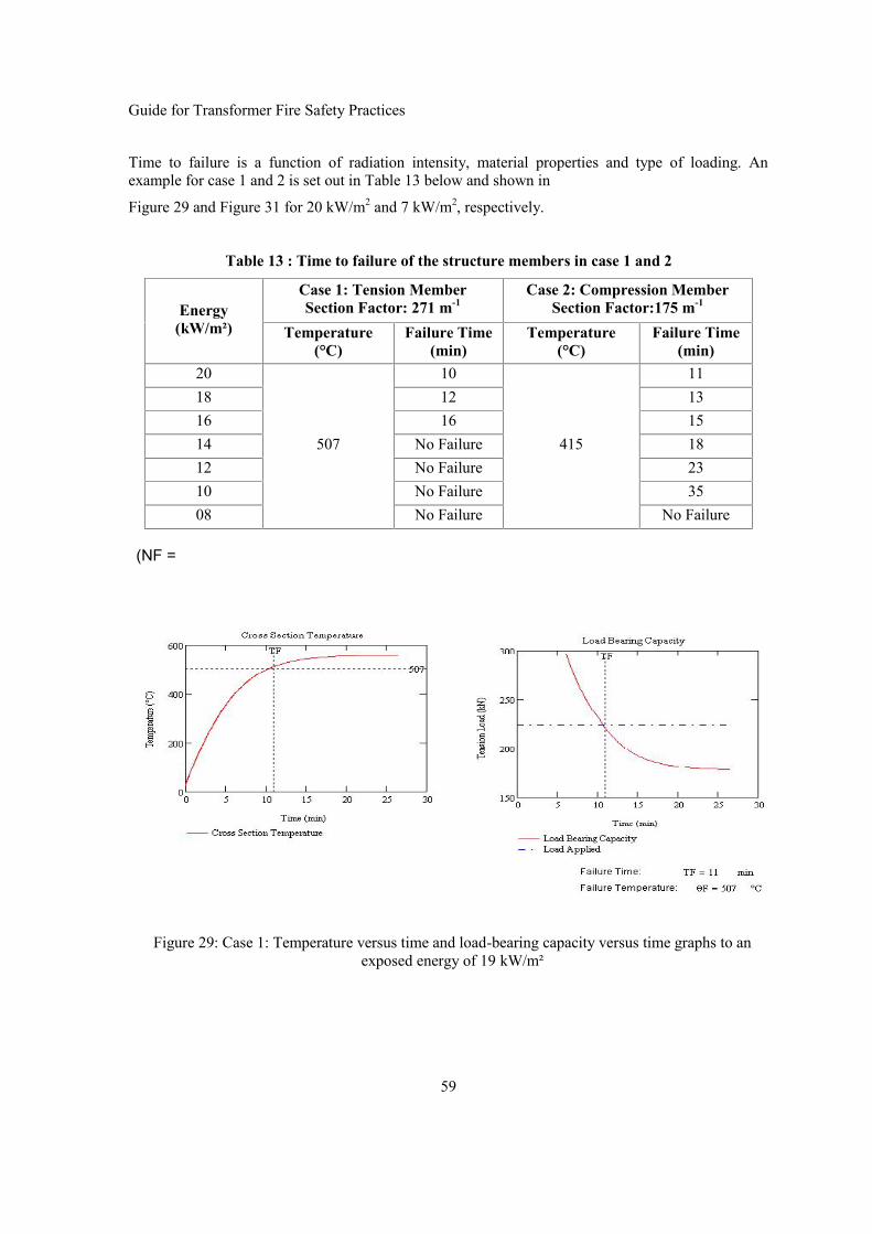
Guide for Transformer Fire Safety Practices
59
Time to failure is a function of radiation intensity, material properties and type of loading. Anexample for case 1 and 2 is set out in Table 13 below and shown in
Figure 29 and Figure 31 for 20 kW/m2 and 7 kW/m2, respectively.
Table 13 : Time to failure of the structure members in case 1 and 2
Energy(kW/m²)
Case 1: Tension MemberSection Factor: 271 m-1
Case 2: Compression MemberSection Factor:175 m-1
Temperature(°C)
Failure Time(min)
Temperature(°C)
Failure Time(min)
20
507
10
415
1118 12 1316 16 1514 No Failure 1812 No Failure 2310 No Failure 3508 No Failure No Failure
(NF =
Figure 29: Case 1: Temperature versus time and load-bearing capacity versus time graphs to anexposed energy of 19 kW/m²

Guide for Transformer Fire Safety Practices
60
Figure 30: Case 2: Temperature versus time and load-bearing capacity versus time graphs to anexposed energy of 20 kW/m²
Figure 31: Case 2: Temperature versus time and load-bearing capacity versus time graphs to anexposed energy of 7 kW/m²
The structure failure depends on fire severity, steel area exposed to the flames, the applied load andsupport conditions. Tension member failures (case 1) are associated with energies higher than16kW/m2. Compression member failure is probable with energies around 10kW/m2. For the firesimulation, neither tension or compression members failures are foreseen, but scenarios are subject touncertainty.
5.11 ConclusionsThe life cycle of a transformer installation involves complex operations which deal with a variety ofday-to-day decisions to keep the business operating. Fire safety is normally low on the list ofimmediate needs. Fire safety moves up the agenda when a fire occurs and the organization’s financialhealth and image are affected.
Fire risk management can mean many different things to the organization. For some companies itinvolves understanding specifically what is at risk, for others it is having a sense of its relativeseverity, and a third course of action is to make a decision about what to do about the risk.

Guide for Transformer Fire Safety Practices
61
Sometimes these issues are addressed in a rigorous, at others in a casual manner, sometimes with amixture of both. Some view fire risk management exclusively in terms of a decision as to what typeof insurance to purchase.
Fire safety performance is dynamic. At one point in time, one may be certain that a failure will notoccur. At others, one may be confident that one will occur. Between these positions there is a windowof uncertainty. Fire safety process performance evaluation requires a different way of thinking fromthe traditional practices, because a narrow emphasis on what organizations should do offers littlehelp.

Guide for Transformer Fire Safety Practices
62
Chapter 6: Fire Risk Mitigation Options for Transformers
6.1 IntroductionThis chapter will discuss some of the options transformer users have in mitigating the risk oftransformer fires. Most of the risk reduction measure carries additional upfront capital cost and theowner of the transformer should make careful consideration (possibly in consultation with otherstakeholders) of what level of fire risk is acceptable for the specific transformer or class oftransformers, given its application and location, both in the network and also to its surroundings.
It is evident that the fire risk which may be acceptable for a 30 MVA sub-transmission bulk supplytransformer located in a two transformer open air widely spaced substation is quite different to that ofa 600 MVA generator step up transformer located close to the turbine hall in a power station, or a 100MVA bulk supply transformer located in a compact urban substation where land cost is high and therisk to both human life and adjacent valuable properties, or the extreme case where the transformer islocated in the basement of a high rise office tower.
In this chapter we will discuss the risk mitigation measures available for transformers.
However, it should be understood the whilst risk of transformer fires can be reduced significantly byusing one or more of the available risk mitigating options, none of these mitigating options cancompletely eliminate the risk of a fire in a mineral oil immersed transformer. It should also beunderstood that it is not possible to cover all possible risk mitigation measures in a short guidedocument like this brochure.
It is therefore strongly recommended that transformer user makes their own assessment or seeksfurther guidance on what type of risk will be reduced and even more importantly assess what risk willnot be reduced from each mitigation measure before deciding what risk mitigation measures shouldbe applied for their specific installation.
Protection strategies available for potential victims of a transformer fire - other substation assets willbe considered and discussed in Chapter 7:
6.2 Minimizing the Risk of Transformer FiresThe first step in minimizing the risks of a transformer fire, is to minimize the risk of a transformerfailure causing the fire occurring. This begins with the transformer specification (and may includeincreased insulation levels and reduced temperature rise) and extends to maintenance and operatingpractices, but also includes the electrical protection installed to clear electrical faults rapidly andprotect the transformer if an external or internal fault occurs.
The second step is directed towards minimizing the risk of a transformer failure developing into anoil fire, if a transformer failure does occurs.
The possibilities for reducing this include: Use transformers which do not use mineral oil asinsulation and cooling medium, and for mineral oil and non mineral oil filled transformers, the choiceof low explosion risk types of bushings, avoiding cable terminations on the transformer terminals andprevention measures applied to the tank to minimize the risk of tank rupture and uncontrolled releaseof oil and arcing gases, and for indoor installation avoiding oil and arcing gases coming in contactwith oxygen (air) if released.
The steps listed above relating to the transformer will be discussed in further detail in the reminder ofthis chapter, and for steps related to the substation installation in Chapter 7.

Guide for Transformer Fire Safety Practices
63
6.2.1 Standard Tanks with Pressure Safety Margin above PRV Opening PressureWhen considering failure rates, there appears to be a correlation between failure rates and specifiedrequirements in so far that utilities who have more demanding specifications and choose to buytransformers from well reputed manufacturers with proven ability to supply high qualitytransformers, also have lower failure rates than transformer users who have less demandingspecifications and is less discerning in their choice of suppliers.
Specifications from these transformer users will in general have additional requirements to thoselisted in IEC 60076, IEEE C 57 or equivalent national standards in terms of permissible flux density,temperature rise insulation levels and requirements with regards to tank strength expressed either interms arc energy containment capability or pressure withstand capability. They typically also specifyrating of bushings and tap changers with margin above the minimum requirements for thetransformer and require that major and critical components such as bushings, tap changers be sourcesfrom suppliers prequalified by the end user. They also pays critical attention to the sourcing of otherkey components such as copper conductors, insulating materials and important ancillaries such gasand oil surge relays, temperature indicators, pressure relief devices, conservator bags.
Their specifications typically have more stringent test requirements and include additional tests tothose required for compliance with the above mentioned standards. They often include tests forverification of overload capabilities to the full extent of intended emergency overloads in terms ofover-voltage and over-current, both in magnitude and duration. They will have stringent requirementsin terms of: permissible levels of partial discharge during overvoltage tests, temperature rise limitsduring over-current tests and specify limits for permissible increases in gasses dissolved in the oilfrom before to after completion of these tests.
They also conduct detailed tender evaluation on offers from prequalified tenders or make carefulassessment and/or Quality Assurance Audits of potential new suppliers. They conduct pre- and/orpost order design reviews to ensure specified requirements are fully understood by the supplier. Theyinspect work in progress and witness critical tests to ensure that the transformers meet or exceedspecified quality and performance requirements. (Cigre Technical Brochure 528 provides Guidanceon Preparing Specifications for Power Transformers, Cigré Technical Brochure 529 providesGuidance for Conducting Design Reviews for Power Transformers Cigre Technical brochure 530provides Guidance for Transformer Factory Capability assessment for Power Transformers).
6.2.2 Enhanced Maintenance PracticesEnhanced maintenance practices can reduce the probability of in-service failures and consequentlythe probability of a transformer failure causing a fire.
The most critical areas to monitor are: The level of the critical gasses dissolved in the oil, the oilquality, the moisture level and condition of solid insulation and especially the condition of tap-changers and bushings. The latter in terms of freedom from leaks, absence excessive increases in tandelta, and capacitance not increasing more than 3-5% beyond the “when new” level. Transformersshould not be allowed to remain in service if the capacitance of the condenser bushings has increasedby more than 5 %, as a bushing failure have a high probability of causing a transformer fire. Tap-changers should be serviced in accordance with the suppliers’ recommendation unless thetransformer owners own experience justifies it to be done otherwise. Off Circuit tap-changers shouldbe operated across the whole tapping range several times periodically to wipe the contacts andmaintain low contact resistance.
Enhanced maintenance can ensure incipient defects are detected and remedied or the transformer isremoved from service before a defect progresses to the point where it develops in a catastrophicfailure.
Guide for Transformer Fire Safety Practices
64
The CIGRÉ Technical Brochure 445 provides guidance on the appropriate levels of maintenance forthe required reliability.
6.2.3 Operating PracticesOperating at high loads beyond the nominal rating carries additional risk. (With loading valuesbeyond the nameplate rating, all the individual limits stated in IEC 60076-7 should not be exceeded.)Transformer users, who intent to load their transformers beyond the rating(s) stated on the ratingplate, should ensure that the transformer and all its elements such as bushings, OLTC’s and CT’s arecapable of such loading and is in fit condition for the intended loading. Ideally the transformer shouldhave been specified and tested at manufacturers work for the intended loading. If this has nothappened then the user should as a minimum precaution, check and ensure that all the series elementssuch as the tap-changer, bushings and bushing line/draw leads and the CT’s all have sufficiently highcurrent rating for the intended overload and that the conservator can accommodate the increasedvolume expansion of the oil without overflowing. If the transformer is located indoor, or in a partialor fully enclosed sound enclosure, then it should also be ensured that the airflow is sufficient for thecooling the transformer when it is operating at higher losses. Dissolved gas analysis should also beperformed on oil samples, ideally before overload commences and again within 24 hour aftercommencing the overloading and again after one week, if the over loading exceeds 1.2 p.u. or if thehot spot temperature of winding, lead or flux shields > 115 oC. Infrared scan can also be used tocheck that terminals and tanks do not suffer from excessive localised hotspot temperatures.
6.3 Protection
6.3.1 Electrical ProtectionFast reliable, duplicate protection together with a fast acting circuit breaker is the most importantdefence in limiting the risk of potential transformer failures from through-faults. Fast protectionminimizes the risk of a through fault casing the failure of the transformer, and in the event of atransformer failure limits energy injected into an arcing fault within the transformer tank and thusreduces the risk of tank rupture. Good protection together with a fast acting circuit breaker canachieve interruption within 2.5-3.5 cycles, 50-70 ms for 50 and 60 Hz systems. The arcing energy fora given arcing fault is directly proportional to the duration of the arc, so minimizing the arcing timeof an in tank arcing, fault reduces the risk of tank rupture and therefore the risk of oil spill and fire.
Guidance on protection schemes for protection of transformers is outside the scope of work by SCA2.Readers are referred to CIGRÉ Technical Brochure 463 - Modern Techniques for Protecting,Controlling and Monitoring Power Transformers [51].
The most common elements of typical transformer protection schemes for the type of transformerscovered by this document are listed below:
Over current protection consists of a relay usually connected to a current transformer monitoring thecurrent on the primary side of the transformer
Earth fault protection is usually provided by monitoring of neutral current or by using restricted earthfault protection which can provide an improved and more sensitive protection against earth faults.
Differential protection is connected to current transformers monitoring the ampere turn current in theprimary secondary and if applicable also tertiary and other additional windings. The relay isactivated if the ampere-turn difference between input and output exceeds a predetermined bias level.Whilst this protection can be very effective in detecting electrical faults within the transformer, its

Guide for Transformer Fire Safety Practices
65
sensitivity is limited by the bias required to allow for inrush current and ratio changes due to tapchanger operations.
Over current, Earth fault and Differential protection are used to provide trip signals to the transformercircuit breaker(s).
Other commonly used Protective Devices include:
Buchholz Relay which provides a signal for gas accumulation in the relay caused by discharge oroverheating in the transformer this signal is normally used as alarm signal. The relay also provides asignals initiated by oil surge from the transformer tank to the conservator and for oil level fallingbelow the mounting height of the relay, these two signals are usually used as trip signals.
Sudden Pressure Relay is sometimes provided on transformer tanks and on bolt on type OLTC’s. Therelay is activated by sudden increase in tank pressure (rate of pressure rise) and is it fitted with acontact which can be used to provide trip signal to a protective relay.
OLTC Oil Surge relay is mounted in oil pipe connecting the OLTC conservator to the diverter orcombined diverter/selector tank and like the Buchholz relay provide trip signal on oil or gas surgefrom arcing faults within the diverter switch or combined selector diverter tank.
Pressure Relief Valve [PRV] typically consists of a spring loaded diaphragm which opens a pre-determined pressure to provide pressure relief by venting of oil and/or gases. It is usually fitted with acontact which can be used to provide trip.
Rupture Discs of various types/design are in use as an alternative to PRV’s. They can open fasterthan spring loaded PRV’s and has less oil flow restriction. Rupture disc systems from some suppliersinclude signalling devices which can be used to generate trip signals and/or activate nitrogeninjection when activated.
Protection by over-fluxing relay: Over-fluxing can be a serious risk if the frequency falls by morethan 5%, especially if it coincides with a voltage rise following load shedding or other systemdisturbances. Over-fluxing of more than 10-20 % can only be sustained for very short period unlessthe transformer is designed with special low flux density. This type of protection is commonly usedfor generator step up transformers.
Over temperature protection: It is common to monitor the top oil and the winding hot spottemperatures and include contacts for alarm and trip on the temperature monitoring devices. Someutilities choose not to have such devices connected to a trip relay, but prefer to monitor transformerfor excessive temperatures manually to reduce risk of an unscheduled load shedding.
Duplicate Protection: It is common to provide duplicate protection [x and y] for larger and importanttransformers. The elements duplicated are usually, the protection trip relays, circuit breaker trip coilsand the most important electrical relays (differential and earth fault) and the current transformerssupplying them, whereas other trip functions are normally distributed between the two trips relays.Other alarm, control of monitoring devices are also commonly used on transformers, however as theirrole is outside the scope of this document, they will not be discussed here.
Current and Voltage Limiting Devices:
Reducing or limiting the current through the windings during external faults can reduce the risk ofinternal winding faults and also reduce the arcing current for internal fault and thus provide asignificant reduction in arcing energy, the risk of tank rupture and consequently the risk of atransformer oil fire. Common methods of reducing the fault current include:

Guide for Transformer Fire Safety Practices
66
Increasing the impedance of the transformer or using an external series reactor. Thedisadvantages of both of these are higher losses and higher voltage drop through thetransformer and the reactor with increased loading losses.
Use of neutral earthing: resistor, reactor or an earthing transformer. These devices onlyreduce fault current for line to ground faults, the most common fault mode, but not for phaseto phase or three phase faults.
Use of current limiters, devices such a fuse which interrupts the supply to the load, if a shortcircuit fault develops on the load side of the device. It can be effective in limiting faultcurrent; however its application is at present limited to medium voltage levels below 50 kV.
6.3.2 Overvoltage ProtectionLightning strikes and other transient over voltages can cause dielectric breakdown and when theyoccur it is often at or near line terminals, cable terminations, bushing line leads or at the line end ofthe winding i.e. locations of high arcing energy.
Metal oxide surge arresters are therefore an important part of transformer protection in reducing therisk of a transformer failure. All line terminals of transformer should be protected by surge arresters.This is particularly important, if the transformer is connected directly to overhead lines, open busbars and also where the last tens or some hundreds of meters are supplied through cables. For suchinstallations it is important that surge arresters are provided both at the overhead line/cable interfaceand also at the transformer terminals as voltage reflection from the higher surge impedance of thetransformer windings and the overhead line can cause voltage build up in the cable and at thetransformer terminals and consequently initiate insulation failure.
6.4 Less-Flammable Insulating MediaIt is possible to virtually eliminate the fire hazard associated with transformer oil fires by selectingdry type transformers or gas insulated transformers and reducing the fire risk significantly by use ofless flammable insulating/cooling fluids.
6.4.1 Dry Type TransformersAs the scope of this document is for transformer with their highest voltage > 66 kV, dry transformerswill not be discussed in this document as they are only in common use at voltage levels below 66 kV,although it is recognised that they have very low, virtual negligible fire risk.
6.4.2 Gas Insulated Transformers (GIT)Gas insulated transformers (GIT) using the inert gas sulphur hexafluoride (SF6) as a cooling andinsulating medium have excellent non-flammable and non-explosive characteristics. GITs are theonly nil fire risk and virtual explosion proof transformers for voltages > 66. GIT’s are widely used inmajor indoor city substation in Japan and other Asian cities and also in some countries outside Asiaincluding Australia. Because of their virtual nil fire risk they have been installed in office buildings,underground substations in urban business districts. They are often located adjacent to, or in sameroom as gas insulated switchgear [GIS] which reduce the cost of inter connections. GIT’s havevirtually absolute fire safety. However, the (SF6) is a very potent green house gas and the potentialleakage to the atmosphere is of concern. Some users have taken significant precaution to minimisethe release of SF6 gas in the event of leakage or unintended spill or accidental release of such gases.The initial cost of SF6 transformers is significantly higher than oil filled transformers. GITs are notcommonly used in Europe or the Americas.

Guide for Transformer Fire Safety Practices
67
The construction of a gas-insulated transformer is basically the same as an oil-immersed transformer(OIT), with the exception of insulating material and cooling medium. Therefore, broad experience ofOIT technology can be applied to GIT design, manufacturing and maintenance. Figure 32 shows anexample of GIT structure, and summarizes the basic features comparison between OIT and GIT.
Figure 32: GIT Structure and Features
There are two types of GITs, determined by the internal pressure of the SF6 gas:
low-pressure types (0.12 ~ 0.14 MPa at 20° C);
and high-pressure types (0.4 ~ 0.43 MPa at 20° C).
Oil Immersed Transformer (OIT) Gas Insulated Transformer (GIT)
Insulation Oil SF6 Pressure 0.14 or 0.43 Mpa (20℃)
Oil Impregnated Paper, Pressboard PET film, PPS film, Aramide paper, Pressboard
Class - A (Max 105℃) Class - E (Max 120℃)
Necessary Unnecessary
Diverter Switch Arcing Switching in Oil Vacuum Interrupter
Tap Selector Slide Contact Roller ContactOn-LoadTap Changer
Insulation / Cooling
Solid Insulation Material
Thermal Class
Conservator

Guide for Transformer Fire Safety Practices
68
The latter type operates at higher gas pressure in order to boost the insulating and coolingperformance of the SF6 gas. In accordance with Japanese domestic regulations regarding the pressurevessels, if the maximum pressure in a gas insulated transformer is to exceed 0.2 MPa duringoperation, the transformer tank should be designed specifically as a pressure vessel.
a) Low Pressure GIT 110kV-50MVA b) High Pressure GIT 275kV-300MV
Figure 33: GIT Application Range
6.5 Less Flammable Insulating FluidsA less flammable fluid is defined as a fluid with a fire point greater than 300oC. Commonly used lessflammable fluids include synthetic or natural ester based oils and silicone based fluids.

Guide for Transformer Fire Safety Practices
69
Whilst the use of such fluids cannot totally eliminate the fire risk they can significantly reduce thefire hazard associated with transformers. But unlike non flammable fluids, less flammable fluids canstill generate a short lived fire ball, if the fluid is released as a mist and then ignited. Although the useof less flammable fluids may carry similar risk of tank rupture, their key benefit is that they will notsupport a long burning pool fire and will in most case not sustain a fire unless energy input iscontributed from other sources.
Whilst these fluids can and will burn at sufficiently high temperatures, it is worth noting that in the30+ years history of less flammable fluids there have, to the best of the knowledge of the WG A2.33members not been any reported transformer fire incidents involving these fluids.
Historically less flammable fluids have been used in distribution and smaller industrial types oftransformers since the polychlorinated biphenyl was banned from use as a transformer fluid in newtransformers. In recent years their use have been extended to larger transformers and a fewtransformers at the 132 and 220 kV system voltage levels are now in use. The interest in their use isnot only for their less flammable properties, but for the esters also for their non-toxic and bio-degradable properties.
A major insurer of industrial plant and assets has developed a standard for less flammabletransformers. This standard takes advantage of the use of less flammable fluid and adds certainprotective and design requirements to prevent the release of the fluid as a mist which can generate afire ball. Transformer manufacturers who build transformers to this standard can earn the insurersstamp of approval. These transformers are treated by the insurer as having the same low fire risk asdry type, gas insulated or silicone fluid filled transformers. This allows reduced separation andbunding.
It is also possible to apply the Insurers guidance for existing transformers retro-filled with lessflammable fluids. Transformers that fall in this category are identified as “equivalent” transformersand would also be considered by the insurer to have the same low fire risk as dry type, gas insulatedor silicone oil filled transformers.
Whilst it is possible to retro-fill existing mineral oil transformers with a non flammable or lessflammable fluid to eliminate or reduce the fire hazard, it is rarely an economic solution for existinglarger mineral oil filled transformers unless it is part of an asset replacement plan or specialrequirements justifies the cost.
Retro filling of power transformers requires qualified engineering assessment for designconsiderations to accommodate the differences between mineral oil and other fluids.
Special attention should be paid to:
the parameters which describe the thermal and dielectric properties of the fluid in regard to agiven design
the compatibility of materials and equipment to the fluid (especially gaskets in order toprevent leakages, operation of the tap changer etc.)
the applied liquid preservation system
6.5.1 Properties of Less-Flammable FluidsIn the past PCB’s were used in transformers as it did not have a measureable fire point and hencewere thought to be an ideal solution. However in the late 1970’s PCB’s were banned from use due tothe fact that they are toxic and harmful to the environment. The phasing out of PCB has led to otherfluids with high fire point being developed as an alternative to mineral oil. The use of these

Guide for Transformer Fire Safety Practices
70
alternative fluids means that the risk of pool fires can be significantly reduced, since the fluid must beraised to a much higher temperature before it will sustain a fire.
Standard O class transformer oil is commonly referred to as “mineral oil” and has a typical fire pointin the range of 120°C to 160°C.
The common, less flammable K-class fluids currently available fall into four categories:
1 High Molecular Weight Hydrocarbon (HMWH)2 Synthetic Ester3 Natural Ester4 Silicone Oil
Table 14 below lists some typical characteristics of mineral oil and less flammable liquids which arerelevant for evaluating their use in transformers. A comparison of performance characteristics of lowflammability fluids can also be found in Table 3 of IEC 60076-14.
Table 14 : Typical Characteristics of Insulating Liquids
Liquids Properties Silicone20cSt
Silicone50cSt
Ester oilNatural
Ester oilSynthetic
Mineral oil
Density (at 15 C) 0.95 0.96 0.92 0.97 0.87
Pour point (C) < -60 < -50 < - 21 < -55 < - 32.5
Flash point (C) > 260 > 310 > 330 > 260 145
Kinematic viscosity(mm2/s at 40 C) 16.0 38.0 33 29 8
Typical fire risk scenario is similar to the scenario for mineral oil filled transformers; however thelow flammability transformers are superior in combustion performance and have good ignition timecharacteristics. Testing result of combustion performance has been reported in several papers [52][53]. The fire of the silicone liquid in open cup tests is smaller than other oils because a silica layer(residue from combustion) is covering the surface of the silicone liquid as combustion progresses andit shut off oxygen the supply to silicone liquid under the flame. However, these properties may beless relevant where the silica layer is mechanically disturbed or the oil is spilling down over a verticalsurface which would break up the silica layer.
In the fluids with higher flash point and/or higher fire point, silicone liquids and ester oils havesimilar good ignition time characteristics. However, silicone liquids have better (lower) heat releaserate than all types of ester oils. Silicone liquids and all ester oils have similar good flame propagationvelocity characteristics. Silicone has higher cooling capability than esters. Low-viscosity siliconeliquids have overall superior characteristics in comparison to esters except for bio degradablecharacteristics where ester based oils are superior.
6.5.2 High Molecular Weight Hydrocarbon (HMWH)Introduced in the late 1970’s, these fluids are based on petroleum oils. In order to raise the fire pointof the fluid, the lighter fractions are refined out of the oil. This leaves a product that has a high firepoint (>300°C), but also higher viscosity, which must be taken into account when consideringthermal design. These fluids also tend to have a relatively high pour point, making them less suitable

Guide for Transformer Fire Safety Practices
71
for use in colder climates. Being pure hydrocarbons, these fluids are fully miscible with mineral oiland can be used to retro fill existing transformers. However these fluids are not widely used intransformers.
6.5.3 Synthetic EstersIntroduced in the late 1970’s synthetic esters as the name suggests are synthesised by reacting acidswith an alcohol to produce the final fluid. These fluids have a high fire point, combined with lowpour point (typically <-55°C). They are oxygen stable and suitable for use in free breathingequipment. Synthetic esters are also typically readily biodegradable, bringing extra benefits for theenvironment. To date these fluids have mainly found applications in distribution transformers andspecialist applications such as traction transformers where their excellent high temperature stability isutilised. In recent years there has been a move towards using synthetic esters in larger powertransformers to increase fire safety. Although Synthetic Esters typically have a higher viscosity thanstandard transformer mineral oil, the higher thermal conductivity of these fluids somewhat offsetsthis, such that their cooling performance is close to mineral oils. Synthetic esters are fully misciblewith mineral oil and can be used to retro-fill mineral oil transformers to increase fire safety.However, the fire point and flame point will be with lowered proportionally to the amount of mineraloil mixed into the less flammable fluids [52].
6.5.4 Natural EstersSince the 1990’s, there has been a move towards introducing the use of vegetable based fluids intransformers. Initially, it was limited to small distribution transformers, but more recently also inlarger high voltage transformers up to 90 MVA 220 kV [54]. However the number of largetransformer using this type of insulating fluid is still small and the in-service history is still verylimited for large transformers. So potential users should ensure they have the up to date informationon all the aspects of this type of fluid before making the decision to use it in large high voltagetransformers. The natural esters are made from a variety of oil seeds, such as soya bean or rape seed.They are usually non toxic and readily biodegradable. Natural esters have a higher viscosity thanmineral oil, which must be considered in thermal design, however the higher thermal conductivity ofthese fluids somewhat offsets this [54]. Natural esters are miscible with mineral oil and can be usedto retro-fill mineral oil transformers, however caution must be taken as the flash point may beinfringed by small residual amount of mineral oil. (Maximum 4% mineral oil to get a 300oCclassification - Refer to “Transformer Fire Protection - Bureau of reclamation”). Natural esters arevery hygroscopic and oxidise very readily and therefore require a hermetically sealed design.
6.5.5 Silicone OilSilicone oil is also a synthetic product introduced in the late 1970’s. It is manufactured via a series ofchemical intermediates generated primarily from sand and methanol. This fluid has a high fire point(>350°C) and excellent thermal and oxidation stability. Silicone liquid has the lower kinematicviscosity for below 20 oC among high flash and fire point liquids (20 cSt), however viscosity changeswith temperature and for temperatures above 40 oC which is the normal working temperature oftransformer silicone oil has higher viscosity than both synthetic and natural esters. Refer to [55] forfurther details of comparative properties of mineral oil, silicone fluids and synthetic and naturalesters.
Historically silicone fluid became the fluid of choice for fire safety in distribution transformers andcompact design traction transformers, where the high temperature stability is utilised after askarelswere phased out. Silicone fluid has found limited applications in larger transformers due to its weakerdielectric electrical strength when compared to other alternative fluids and its tendency to form gelsunder arcing conditions. Environmental safety is also an issue with silicone oils, as these are

Guide for Transformer Fire Safety Practices
72
extremely slow to bio-degrade. Concern has also been raised with fumes from burning silicone fluidin enclosed spaces. It has been reported [53] the fumes clog breathing apparatus filters and thevisibility in silicone oil smoke is very limited. However, WG A2.33 does not have specificinformation to verify or disprove these points. Although Silicone oil is miscible with mineral oil itcan lead to foaming problems in oil processing equipment. For this reason the retro-filling of mineraloil transformers with silicone oil is generally not recommended, and oil treatment equipment used forsilicone oil should not be used for other types of insulating oils.
6.5.6 Combustion Characteristics and Test ResultsCone calorimeter method in IEC60695-8-3 (Draft) was used to conduct evaluation of combustioncharacteristics and thereby to evaluate the fire risk of 20cSt silicone liquid immersed transformers bya Japanese laboratory.
The samples were heated by a conical heat-transfer heater in the experimental apparatus, andflashing/ignition was induced by applying a spark to the produced gas. The changes in the samples'heat release amount, gas production amount, weight, and combustion product gases over time weremeasured, and each sample's combustion weight loss rate when loaded with a particular radiant heatflux was determined. The insulation fluid samples were kinetic viscosity 20cSt and 50cSt siliconeliquids corresponding to the high flash point insulation fluids of IEC-60076-14. They were comparedwith two other fire-resistant insulation fluids – synthetic ester oil and natural ester oil – and with theconventionally used mineral oil.
The pictures and the graphs in Figure 34 below show the experimental results when each insulationfluid was loaded with a particular radiant heat flux. Results for four fluids were experimentallyderived in terms of: heat release and smoke production.
In terms of maximum smoke production rate, the ranking from this test was: mineral oil > naturalester oil > 20 cSt silicone liquid > 50 cSt silicone liquid > synthetic ester oil. The silicone liquidshave a low maximum smoke production rate compared with the other insulation fluids. The fire ofthe silicone liquid is smaller than other oils because a residue silica layer formed by the combustioncovers the surface of the silicone liquid and it is shut off oxygen supply to silicone liquid under theflame. However, these properties may be less relevant where oil is spilling down over a verticalsurface which would break up the silica layer.
In terms of maximum heat release rate, the ranking was mineral oil > natural ester oil > syntheticester oil > 20 cSt silicone liquid > 50 cSt silicone liquid.

Guide for Transformer Fire Safety Practices
73
a) Time histories of the smoke productionrate of burning insulation fluids.
b) Time histories of the heat release rate ofburning insulation fluids.
Figure 34: Comparative Combustion Test Results
Synthetic Ester OilSynthetic Ester OilSynthetic Ester OilSynthetic Ester Oil Silicone liquidSilicone liquid
Silica FormationSilica Formation
Silicone liquidSilicone liquid
Silica FormationSilica Formation
Mineral oilMineral oilMineral oilMineral oil Natural Ester OilNatural Ester OilNatural Ester OilNatural Ester Oil

Guide for Transformer Fire Safety Practices
74
6.6 Tank Design as Protective StrategyIf the oil and arcing gases can be contained in the transformer tank during and immediately followingan arcing fault then there will not be any fire. Unfortunately there are at present no internationalstandards for the design and testing of transformer tanks.
To the best of the knowledge of WG A2.33, Japan is the only country which has a national standard(design guide) with requirement for the design of transformer tanks. The development of theJapanese Standard [17] (design guide) followed extensive research and verification testing of waterfilled tank with internal arcing simulated by ignition of powder charges.
For other countries, design and verification testing of transformer tanks is therefore often non-existing, unless the individual transformer purchaser has included such requirement in theirpurchasing specification.
The following subsections will give a brief description of the issues related to containment of internalarcing with the majority of this information extracted from the Japanese standard for design of highstrength transformer tanks.
6.6.1 GeneralThe transformer tank structure varies depending on the purchaser’s specification, the requiredtransportation method and the individual manufacturer's design standard, etc.
In general, the transformer tank is commonly designed to withstand full vacuum (zero internalpressure), stresses related to the mode of transportation and over pressure related to the static head ofoil pressure with a safety margin, or if included - the requirement detailed in the purchaser’sspecification.
However, only few purchaser specifications include specific requirements for the rupture withstandstrength of transformer tanks. I.E. , the estimated internal pressure (P0) developed from internalarcing under credible internal fault conditions.
Ideally the transformer tank design should be coordinated with pressure control measures and thespecified fault level/time characteristics, to ensure that the internal pressure build up during internalarcing faults does not exceed the verified design withstand strength of the tank. However, ensuringthis poses many difficulties for high arcing energy faults, and only a very small percentage oftransformers presently in service would be able to meet such a requirement.
Firstly, because the potential arcing energy is difficult to calculate with a reasonably degree ofaccuracy and secondly, the commonly used Pressure Relief Protective Devices are in general not ableto respond sufficiently fast and with sufficient relief capacity to prevent the tank from rupturing, ifexposed high energy arcing fault (refer Chapter 4:).

Guide for Transformer Fire Safety Practices
75
The diagram below depicts the requirement for ideal protective performance of a Pressure ReliefDevice.
Pressure
Figure 35: Ideal protective performance of a PRD time
6.6.2 Tank Strength RequirementsA prerequisite requirement for good tank design is knowledge of the required tank strength. In theabsence of a standard for required strength for tanks to withstand internal arcing fault, it isrecommended that the reader refers to Chapter 4: of this document for guidance, unless he has bettermethods at his disposal.
However, it should be noted that guidance provided in this document cannot and does notguarantee that this will ensure that the transformer tank has the required strength to protectthe transformer tanks from rupture under all internal arcing faults conditions and certainlynot from a fire, as only a minor part of transformer fires originates from tank rupture.
6.6.3 Tank DesignThe transformer tank is a welded structure consisting in general of plates with stiffeners and isequipped with some bolted connections at flanges for bushings, tap changers and access /inspectioncovers. The structural design of a transformer tank includes the analysis for various types of loads thetank is exposed to. The determination of the stresses and deflection under various load conditionsrequires a certain number of simplifying assumptions, due to the high number of accessories, fittings,welding-joints and different tank-shapes present on a transformer tank. The stress analysis of atransformer tank can be done either by analytical or by numerical methods (FEM). In both cases theanalysis is based on static considerations and focused on the objective to limit the stresses and thedeflection during to remain within the elastic deformation range of the tank material.
For the majority of transformers installed so far, considerations regarding the mechanical stresses onthe transformer tank structure resulting from an internal arcing fault, were not necessarily included inthe normal design process. The dynamic ability of a transformer tank to resist internal arcing can onlybe demonstrated by testing. However it is commonly acknowledged practice that a rupture strengthtest for larger transformer tanks is normally not applicable; therefore the resistance of a transformertank to internal arcing can only be proved with limited accuracy by a simulation calculation.
Different calculation methods are available to evaluate the pressure rise developed by internal arcingand the resulting mechanical stresses on the transformer tank. Any model, particularly of such acomplex system, is necessarily approximate. From the point of view of practical application the useof the formula in Chapter 4: of this document may be an appropriate approach for handling thecomplexities of the pressure rise which is associated with an arcing fault in a transformer tank.Equation 3 for the estimated internal overpressure, developed from internal arcing under credible

Guide for Transformer Fire Safety Practices
76
internal fault conditions, reduces the transient nature of the pressure rise into a quasi-staticconsideration. The numerical analysis of the tank design considers the homogenous internaloverpressure as a function of the volumetric stiffness behaviour of the tank structure. The calculationhas to prove that the transformer tank may become largely plastic deformed, but has to remain fluid-tight because its rupture withstand strength meets the estimated internal overpressure at least.
The rupture withstand strength of a transformer tank can be determined based on the elastic-plasticmaterial behaviour, as the tank rupture occurs when the materials are stressed beyond their elasticdeformation range.
If arcing fault withstand strength is required then the Purchaser should specify the simulationcalculation required for proving the rupture withstand strength of the transformer tank to internalarcing as well as the required fault energy, or the fault current and the clearing time (for details seeChapter 4:). The analysis of the rupture withstands strength of a transformer tank should beaccompanied by considering following items:
Welding skill
Method for estimated pressure at internal fault
Verification experience for tank rupture strength
6.6.4 Improvement of the Tank StrengthThe weak points for the tank rupturing by internal pressure identified in the Japanese guide for tankdesigns are joined flanges and the corner seams of the tank. Reinforcement of these parts, canimprove the rupture withstand strength of the tank.
Figure 36 shows an example of a method for reinforcement of a weak point: joining flanges. Thissimple modification proved to be very effective in increasing the pressure withstand withoutincreasing the overall tank stiffness [37] [39].
Figure 36: Example of reinforcement at joining flanges
6.6.5 Pressure Reducing TechniquesTo reduce the internal pressure during an internal arcing fault, following measures are effective:
Increase tank flexibility:
Increasing the tank flexibility allows volume expansion and thus reduces the pressure rise andespecially the pressure rise gradient. Conversely, increasing the reinforcement to improve the tankrupture strength decreases the flexibility of the tank and thus increases the pressure rise when an

Guide for Transformer Fire Safety Practices
77
internal fault occurs. However, reinforcing for improving the strength locally at stress concentrationpoints is effective. The reinforcement should be appropriately arranged for the stress relaxation ofthese parts of the tank whilst at the same time maintaining tank flexibility. A number ofrecommended techniques are described in [44].
Increase expansion volume:
It is possible increase expansion volume by using a conservator with large diameter connecting pipeas shown in Figure 37 [39]. This technique is sometimes used by Japanese manufacturers forreducing the internal pressure of the tank. If the tank flexibility is low and there is a risk that thepressure rise might exceed the tank withstands strength, then it is useful to utilize a diaphragm or bagtype conservator as a pressure reducing space. The values of the pressure reducing space and theconnecting duct size shown in Figure 37 were obtained from tests on a full-scale model. The data arereferenced to the maximum pressure generated with no pressure reducing space.
A volume increase of about 1,000 litres can decrease the maximum pressure to 70-80% during anarcing fault compared to the no volume increase. A larger volume can reduce the pressure further, butwith decreasing pressure reducing effect. A pressure reducing effect of more than about 20 % can beobtained with connection pipe openings of 900 mm or more. A larger duct size makes no furtherchange in pressure reducing effect. Optimum volume and duct size are considered to dependsignificantly on the tank's expansion coefficient (i.e., the flexibility of the tank); this should be takeninto account in the actual tank design for reducing the internal pressure.
Figure 37: Pressure reduction effect of an expansion volume

Guide for Transformer Fire Safety Practices
78
6.6.6 Gas Cushion TransformersHermetically sealed transformers with air or nitrogen filled space in the upper level of theTransformer to compensate for volume expansion of the oil during load cycling, have inherentlymuch lower rate of pressure rise during arcing fault due to the compressibility of the large gas space.Also a PRV fitted to the tank wall in the gas space area above the oil has much larger volume ventingcapacity for air than one fitted below level of oil (see Chapter 4:). Such design is particular useful forsmall and medium size power transformers.
6.6.7 Verification of Pressure Withstand CapabilityIn the verification tests for the rupture strength of the tank, there are two methods which could beconsidered, one is the dynamic test and the other is the static test.
For a dynamic pressure rise, an electrical test is difficult because of the limitation of the shortinggenerator capacity and the difficulty to obtain an adequate test place, etc. Powder combustion [37] orair pressure methods [56] [57] have been used for simulating pressure rise occurring during internalarcing fault. Generally, it is too difficult to verify the tank strength by the dynamic method mentionedabove due to limitation of test equipment, test space, cost, etc.
A hydraulic static pressure test is therefore a useful alternative for tank strength verification. Figure38 shows the comparison between the dynamic stress by powder combustion test and the static stressby hydraulic pressure test. The dynamic stresses are good agreement with the static stress.
Therefore, the tank strength at internal fault can be verified by the hydraulic test.
Figure 38: Comparison between Dynamic and Static Pressure Testing
6.7 Pressure Venting & Depressurization as Protective StrategiesA variety of pressure reduction techniques have been developed to provide pressure reduction againstexcessive pressure being developed by arcing fault within transformer tanks, tap changer tanks andoil filled cable boxes. Some of these solutions are very basic and their pressure relief effectiveness isvery limited and in general insufficient to provide sufficient pressure relief for other than low arcingenergy faults. Others are more sophisticated and provide faster and higher relief capacity. Someinclude additional feature such as contacts for trip signals, self resealing after pressure subsides, safe

Guide for Transformer Fire Safety Practices
79
venting and separation of oil and arcing gases, and may activate nitrogen injection if fire has beeninitiated. The following sections provided a brief description of the most common devices.
Also refer to Chapter 4.5 for discussing of venting efficiency of pressure relief or depressurizationsystems.
6.7.1 Goose Neck Explosion VentThis type of pressure venting is the simplest and oldest form of pressure relief. It consist of a pipetypically raising from the tank cover to the height of the maximum oil level in the conservator atwhere the pipe is typically formed with bend of approximately 150 degrees to ensure ejected oil andgases is directed away from the transformer. The exit opening is covered by a diaphragm designed torupture at a pre-determined pressure. The diameter of the pipe is designed to provide suitablepressure relief. The benefit of this solution is low cost. The disadvantages is the head of oil in thepipe and possible remoteness from the fault location, which may provide a back pressure whichreduces the effectiveness of the venting for high energy arcing faults, and the spilling of oil andventing gases from a high point above the transformer which add to the risk of ignition of vented oiland gases. To provide effective pressure relief during high energy arcing faults would require severallarge diameter pipes located at several venting points on the tank and re-enforcing of the tank toensure that it can withstand the pressure required to rupture the diaphragm and accelerate oil/gasesagainst the head of oil in the gooseneck pipe. Whilst a sufficient number of gooseneck pipes togetherwith reinforcing the tank could provide pressure relief for relative high arcing energy faults, thereality seems to be that that most transformer users and designers do not realise how large ventopenings / tank strength are necessary to relieve the pressure fast enough to avoid tank rupture duringa high arcing energy fault. This is evident from the many examples of the transformer tanks havingruptured whilst the gooseneck diaphragm still remains intact. The reason for this is that mosttransformer using this type of pressure relief protection has insufficient tank strength combined withtoo few or too small vent openings to have effective protection against tank rupture in the event of ahigh energy internal arcing fault.
6.7.2 Pressure Relief Valves (PRV)This type of devices consists of a spring loaded valve with a dual gasket sealing systems mounteddirectly on the transformer tank typically on the transformer tank side near the top of the tank. PRV’sare also commonly referred to as PRD’s. The valve opens at a pre-determined differential pressureacross the valve. The benefit over the goose neck type pressure relief and rupture disc vents is that itwill reseal when the pressure differential across the valve has reduced to typically 50-60 % of theopening pressure. The PRV’s can be fitted with contacts to provide trip signals when activated andalso with pipe work to direct the oil and gasses towards the base oil the bunded area. PRV’s areavailable in a range of sizes. A 5 inch (127mm) opening diameter is a very common size. It iscommon to fit one PRV to small and medium size transformers and 2 PRV’s to the tank of largertransformers. One manufacturer of a common brand of this type of PRV recommends one valvetransformer up to 40000 L of oil and two valves for larger tanks. Some utilities would use up to 4valves for large transformers. The PRV can be fitted with pipes to direct oil and gasses to a “safe”point at ground level within the bunded oil containment area.
The disadvantage over the rupture disc is that opening time is longer and its venting path has higherflow resistance. The advantage is the valve will reseal after the protection has cleared the fault, forfaults with arcing energy within the withstand capacity of the tanks and the venting capacity of thevalve.

Guide for Transformer Fire Safety Practices
80
Whilst there a many reported cases on PRV having operated with and without tank rupturing, it is theview of WG A2.33 members that one or two PRV’s cannot be relied upon to prevent tank rupture forhigh energy arcing faults.
However, as discussed in Chapter 4 venting efficiency improves for faults located close to theventing port where the vented product is gasses and it is considered that PRV venting can be effectivefor gas cushion transformers where the arcing is below the oil and valve is mounted above the oillevel, as the volume of gas which can be vented through PRV during a very short opening time ismuch higher than for oil (refer Figure 15).
6.7.3 Rupture DiscsRupture disc has advantages above the gooseneck type pressure relief vent in so far they can bedesigned to rupture with far less tolerance on the differential pressure across the rupture disc than canbe achieved with “Goose neck” type pressure relief. They can also be mounted directly on thetransformer tank, and therefore respond faster to excessive pressures. However rupture discs alsorequires collection pipe work and holding tank for the collection /separation of vented oil and gases,as they would poses a serious fire risk if oil and gases were vented freely to the ambient atmosphere.
6.7.4 Tank Protection Systems Based on Rupture Discs and Nitrogen InjectionOne supplier of transformer fire protection equipment which has carried out extensive research intotransformer fire protection offers a combined transformer pressure relief/fire protection system. Thepressure relief part of their system utilizes a single or multiple rupture discs for pressure relief onmain tank (depending on customer willingness to invest) and separate rupture discs for pressure reliefon the tap changer tank and each cable box. The system comprises, a conservator shut-off valve, pipework and a holding/separation tank for collection and separation of the vented oil and explosivegases, and nitrogen injection equipment for injection of nitrogen into the base of the main tank forevacuation of the explosive gas after the tank explosion has been avoided. The purpose of thenitrogen injection is to also to stir the oil and extinguish a fire, in the event the tank has ruptured anda fire has been initiated. The size and the number of the rupture discs will vary depending of faultlevel and tank design parameters, but each rupture disc is generally less than 30 cm in diameterbecause it is difficult to adapt larger discs to standard transformer tank design.
The manufacturer of the transformer protection equipment has carried out modelling calculations andtesting of the pressure relief capabilities of his equipment on full size transformer’s rated up 20 MVAand with arcing energy level of up to 2.4 MJ. The manufacturer claims that modelling andcalculations performed by the company has verified that the system is capable of preventing tankrupture for fault level much higher fault levels than the levels verified by tests.
The manufacturer has named the system describe above as "Fast Tank Depressurisation Technique[FTDT]" [58] [59] [60].
"Fast Tank Depressurization" is recognised as a method of fire protection for transformers in NFPAcodes 850 and 851. NFPA describes Fast Depressurisation Systems "as a passive mechanical systemdesigned to depressurise the transformer within a few milliseconds after the occurrence of anelectrical fault". The is no specific quantitative measure given in the NFPA documents for whatventing capacity is required to qualify for being a “Fast Depressurisation System”.
Other suppliers also offer variants of this type of transformer fire protection system. One of thesesuppliers offers a system which pro-actively opens a large oil drain valve and initiates nitrogeninjection in response to an internal fault detected by the transformer differential or the master triprelay, in addition to trip signal from a Rapid Pressure Rise Relay, a PRV or a Buchholz Relay. Whilstsuch a protection system may cause dumping of oil and injection of nitrogen for internal arcing fault,

Guide for Transformer Fire Safety Practices
81
which could have been cleared by conventional protection and possibly contained within the tankwithout causing tank rupture and fire, the vendor of this system considers that dumping of the oil intoa oil gas separation/collection tank and injection of nitrogen is a worthwhile safety precautionwhenever internal arcing is present.
The WG A2.33 has insufficient experience with the above systems so intending users should do theirown investigations into the merits of these systems.
6.7.5 Tank Protection Systems Using Multiple Rupture DiscsAt least one transformer manufacturer has built transformer tank pressure relief protection based onthe use of multiple rupture discs for pressure relief, in order to increase the effective total ventingarea and to increase the likelihood that a rupture disc will be located in the vicinity of the fault. Onemanufacturer has produced at least one large transformer with a large number of rupture discs andextensive pipe work for gas/oil collection. This manufacturer has also published a paper withcalculations of pressure reduction they consider achievable for a 48 MJ. 83 ms arcing fault with 2, 4,6 and 8 rupture discs. The published paper did not detail the size of the venting apertures. Theyconcluded that to achieve a 30 % reduction of the peak pressure for an arcing fault located anywherein the tank would require 8 rupture discs. The calculated results tabulated in their published paper[45] are listed in the table below. It can also be noted that, according to this analysis, a 48 MJ arcwould produce an internal pressure (1500 kPa) far above the current tanks withstand capability (about200 kPa) and that 2 rupture discs would only reduce that peak pressure by about 3-5%.
Table 15: Pressure reducing effect of multiple rupture discs
Arcing position Tap changer Upper winding part
No. of rupturedisk
Exhaustedpressure
(kPa)
Peak pressure onthe tank wall
(kPa)
Exhaustedpressure
(kPa)
Peak pressure onthe tank wall
(kPa)
0 0 1480 0 1590
2 70 1410 58 1532
4 250 1230 155 1435
6 286 1194 201 1389
8 446 1034 376 1214
The manufacturer has not made any claim in the published paper on how many rupture discs wouldbe required for a given fault energy /tank design, but merely conclude that "that because the arclocation is random, pressure relief points should be installed at multi positions on the tank wall toensure that a t least one pressure relief point will always be located in vicinity of the arc", and thatbased on the procedure listed in the referenced paper, it is possible to determine the number andpositions of rupture discs required to keep the tank wall pressure under the allowable pressure nomatter where the arc takes place.
Whilst there a many reported cases on PRV having operated with and without tank rupturing it is theview of WG A2.33 members that one or two PRV’s cannot be relied upon to prevent tank rupture forhigh energy arcing faults. However, as discussed in Chapter 4: venting efficiency improves for faultslocated close to the venting port.

Guide for Transformer Fire Safety Practices
82
6.8 Choice of Components as Protective Strategies
6.8.1 BushingsIt is known that high voltage Oil Impregnated Paper [OIP] bushing failures are the single componentwhich causes the highest number of transformer fires. Refer to Chapter 2.2.3 Transformer BushingFire Scenarios and Chapter 3: for statistics
It is considered that Resin Impregnated Polymer [RIP] Insulated bushing has the lowest fire risk ofany condenser type HV bushing bushings. Using RIP High voltage bushings is most cost effectivemethod of reducing the risk of transformer fires.
For low voltage bushings; oil filled solid stem porcelain bushings is the type of low voltage bushingswith the highest fire risk. The reason is that when this type of bushing breaks there is a high risk thatit will cause a serious oil spill as oil will be emptied from the conservator and higher part of the tankand if the breakage occurs during an arcing fault, as it often does in a cable termination fault withinan air insulated cable box, then there is a high risk that the oil will be ignited and a serious oil firewill follow.
Plug in type low voltage connections, RIP or moulded resin type low voltage bushings have muchlower risk of causing a serious oil spill than the oil filled solid stem porcelain type bushings.
6.8.2 Cable Terminations and Cable BoxesCable termination failures and cable box ruptures are the 2nd highest cause of Transformer fires.Refer 2.2.4. If an arcing fault occurs in a cable box then there is a high risk that the cable box will beseriously damaged and an oil spill will follow. This is not only the case with oil filled cable boxes.But even more so with air insulated cable boxes without explosion venting. If an arcing fault occursin air insulated cable box which does not have arcing fault venting and oil filled solid stem porcelaintype bushings are used then there is a high risk that the bushings will break and an oil spill willfollow and the oil will be ignited by the arc.
The simplest and most effective risk mitigation measure against arcing fault in cable boxes is to avoidthe use of cable boxes. This can be done by terminating cables at a cable termination pothead at ashort distance from the transformer and make the connection to cover mounted bushings on thetransformer by flexible links or short bus bars. If a cable termination fault occurs, then this will ingeneral not affect the transformer.
As an alternative to terminating cables in a cable box, consider using moulded type bushings withplug-in type connectors.
If a cable box is used then the following risk mitigation measures should be considered:
6.8.3 Insulating Liquid Filled Cable BoxesFor high voltage cable terminated in cable boxes, consider using single phase cylindrical cable boxes,fitted with a large opening PRV’s at the top cover of the cable box and the top flange also being theweakest point of the cable box. Arrange oil expansion containment so oil from main conservator andthe transformer tank will not be drained a spilled from the cable box if top flange or other parts of thecable box rupture. For low and medium voltage cable terminations, consider using moulded resintype bushings or plug-in type connectors.

Guide for Transformer Fire Safety Practices
83
6.8.4 Air Insulated Cable BoxesAn air filled cable box should always be fitted with pressure relief venting. So if an electric arcoccurs then the arcing gases (hot air) is vented away without causing excessive and damagingpressure rise within the cable box. This safety measure is common practice with air insulted metalclad switchgear. If this is not done, then there is a serious risk the cable box will be totally destroyed,and with bushings breakage, possibly oil spill and fire a high probability if a cable termination faultoccurs...
6.8.5 SF6 ConnectionThe direct connection of a transformer to SF6-metal enclosed switchgear is often achieved by oil-SF6condenser bushings with specific gas tight sealing system or an intermediate chamber, which caninsure than SF6 gas is not leaking into the transformer or oil into the SF6 bus bar chamber. This typeof bushing arrangement has significant lower risk of causing a fire than connection via OIP bushingor cables.
6.8.6 Conservator Shut-off ValveThis type of valve is fitted in the oil pipe connecting the conservator and the main tank, but can alsobe fitted between the conservator and oil filled cable boxes. The typical shut off valve is a flap valve,where the flap is held in a partial open position by a spring. This allows oil flow in both direction at aflow rate which occurs to compensate for thermal expansion and contraction within the normaloperation of the transformer. However the valve will close “shut-off” the oil flow from theconservator and initiate an alarm, if abnormal oil flow occurs from the conservator to the main tankor associated cable boxes, as would occur if oil filled solid stem porcelain bushing breakage, or OIPbushing failure, or rupture to the main tank had occurred.
The benefit of the shut off valve is substantial, as it can prevent the oil from the conservator beingspilling out through a bushing turret, damaged bushings, ruptured cable box or a minor rupture nearthe top of the main tank and thus reduce the amount of oil (fuel) spilling from the conservator andfeeding the fire at the early and very critical stages of fire.
However, whilst the concept of the Shut-off valve is very good, it is the WG A2.33 membersexperience that it is difficult to ensure that the valve closes consistently at the required oil flow (notto low and not too high) as it seems that the flow rate at which the currently commercially availablevalves operate varies considerably, and are very dependent on the mounting angle and the head of oilabove the valve.
6.8.7 Tap ChangersThere is often a need to be able to provide voltage regulation by means of an On Load Tap changer(OLTC) or an Off Circuit Tap Changer (OCTC), (also known as De–Energised Tap Changer DETC).Modern day tap changers supplied by a well reputed manufacturer and maintained correctly are veryreliable. Tap changers are only the root cause of approximately 10 % of transformer fires.
The most effective risk mitigation measures for tap changers are:
Ensure the tap changer has ample capacity for its duty, including any intended short termemergency overloads both in terms of insulation class and current rating.
Ensure the tap changer is only maintained by personnel that have the skills and competenceto maintain the type and model they maintain.

Guide for Transformer Fire Safety Practices
84
Ensure that the tap changer is maintained in accordance with the OEM’s instructions, unlessyou as user have proven superior information on its maintenance.
Always check with the OEM if there has been any maintenance requirement updates issuedsince the printing date of your service manual before commencing maintenance.
Maintain and check the oil quality for the diverter / combined diverter/selector tank regularlyand including DGA. DGA interpretation and other forms of online monitoring such asvibration analysis, runtime and motor current on OLTC’s are still at the early stages ofknowledge for its interpretation. However, the body of knowledge is growing and should bemade use of.
Operate tap changer across the whole range of tapping positions several times periodically(with transformer de-energised) to wipe and clean the contacts to maintain low contactresistance and avoid pyrolitic carbon growth. This type of operation is especially importantfor De–Energised (DETC) types of Tap Changers.
Specify, whenever possible, the installation of the tap changer on the neutral end of the Wyewinding, so that energy (voltage) is limited in case of a fault.
Specify a vacuum interrupter technology with less-flammable fluids.
Guide for Transformer Fire Safety Practices
85
Chapter 7: Transformer Fire Damage Control Practices
7.1 IntroductionThis chapter will discuss strategies available to control the impact of a transformer fire on potentialvictims. In this context potential victims include humans, economic assets and the environment.
Humans, include utility staff that may be exposed to the risk of injury due to proximity to atransformer fire in course of their normal duty, fire brigade staff in event of fighting a transformerfire, and members of the public which could be in the vicinity of a substation or other transformerinstallation when a transformer catches fire.
Economic asset at risk as victims to a transformer fire are primarily nearby substation or powerstation plant, equipment, buildings or structures within close proximity of the transformer.Transformer installation and substations located in a city buildings where the public have access tothe building or adjacent buildings requires special considerations; both in terms of risk to human lifeand high value assets.
The major risks to the environment is primarily from spill of oil or other forms of insulating fluid,water contaminated by oil, foam and other fire fighting chemicals, but it also include risk of airpollution from accidental released gases and smoke from a fire.
It is not possible to provide a single set of simple uniform guidelines as each installation must complywith the national and local laws, regulations and codes of practice applicable for each type ofinstallation, both in terms, buildings codes and regulations, and also Laws, regulations and codes forfire prevention and protection of the environment. Laws, regulation and codes vary from country tocountry and even between states within the same country. Climatic and local site conditions also varyconsiderably, this means that a solution which is suitable for one location may not be suitable forother locations.
In this chapter we will discuss the risk mitigation measures available to mitigate the risk of atransformer fire causing damage beyond the transformer already at fire, and provide examples for arange of typical transformer fire control and risk mitigation measures. However, it is not possible toall the variants of Substation installations.
Most of the risk reduction measures carries additional upfront capital cost and the owner of thetransformers should make careful consideration (possibly in consultation with other stakeholders) ofwhat level of fire risk is acceptable for the specific transformer or class of transformers, given itsapplication and location, both in the network and also to its surroundings.
It is evident that the fire risk which may be acceptable for a 30 MVA sub-transmission bulk supplytransformer located in a two transformer open air widely spaced substation, is quite different to thatof a 600 MVA generator step up transformer located close to the turbine hall in a power station; or a100 MVA bulk supply transformer located in a compact urban substation where land cost is high anda transformer fire imposes risk to both human life and valuable adjacent properties, or the extremecase where the transformer is located in the basement of a high rise office tower.
It should also be understood that it is not possible to cover all possible risk mitigation measures in ashort guide document like this brochure. It is therefore strongly recommended that transformer usersmakes their own assessment or seeks further guidance on what type of risk will be reduced, and evenmore importantly, assess what risk that will not be reduced from each mitigation measure whenassessing; Which risk mitigation measures is required by laws and statutes, which may haveeconomic merit as well as to be “Good Fire Safety Practice, before finally deciding what riskmitigation measures should be implemented at the specific site.
1.1.1.1.1.1 Pressure
1.1.1.1.1.2 Time

Guide for Transformer Fire Safety Practices
86
The primary fire spread mechanism for transformer fires is the flow of burning oil beyond the originof the fire and heat radiated from the transformer fire. Transformer fires are essentially large oil fires.Oil containment is therefore most the effective means of reducing the spread of a fire and should beprovided for all oil filled transformers of the size covered by this guide ( > 10 MVA).
7.2 Standards and GuidesA number of useful standards and reference guides with information on how to minimise risk of firedamage to and from transformers have been developed and published by standard organisations,utility associations, insurance companies and utilities. Please refer to the listing such documentsprovided in section 1.4 of this brochure. These guides and standards can be accessed by readers ofthis document for reference and further guidance on a much wider range of fire safety topics and infurther details than it is possible to cover in a short document like this technical brochure
7.3 Fire Control MeasuresWhen a transformer failure has developed into a transformer fire, the transformer is in most casesdestroyed beyond economic repair.
The aim of fire protection control measures is therefore directed to minimize the damage to the fire“victims” generally in the following in the order of priorities:
Minimize risk of loss of life and injury to humans. Minimize the risk of the fire spreading or causing damage to adjacent transformers, control
building, structures and other items of plant and equipment which is critical for maintainingsupply during a transformer fire or restoring supply quickly after a transformer fire if supplycannot be maintained during the fire.
Minimize contamination and damage to the environment. Minimize overall economic loss in the event of a transformer fire.
7.3.1 Minimising the Risk of Loss of Life to HumansWhilst the probability of a transformer explosion and/or fire is a very low, it can be a catastrophicevent if it happens, with the potential to cause injury or death to anyone in close proximity to thetransformer when it happens.
Minimizing this risk therefore begins with restricting access to energized transformers.
Some access for performance operational and maintenance tasks is unavoidable, but it should berestricted to qualified and authorized staff and limited to the degree necessary for operating andmaintaining the transformer and ensuring entrapment does not occur.
If a transformer is located within a sound enclosure, then the spacing around the transformer shouldbe such that it does not impede escape and the enclosure should have at least two outwards openingaccess/escape doors, located at diagonal opposite corners.
Transformers installed in vaults or indoor substations require special consideration for personnelsafety, both in terms of safe escape routes and the fire suppression systems.
If oxygen exclusion gases such as CO2 or others oxygen displacement gases are used, then it isessential that all personnel inside the area to be flooded with the fire suppressant gas are evacuatedbefore the gas is released. Normal safety procedures for such fire suppressant systems include dualfire signal interlocks, warning/evacuation siren operation for 30-60 seconds, closing of vent andstopping of fans and unless impossible, de-energizing of the transformer before the fire suppressantgas is released. Trip signals from electrical protection relays, Buchholz or PRVs should not be usedalone to initiate automated fire suppression system.

Guide for Transformer Fire Safety Practices
87
Proximity and access to transformers for the public should be restricted to the very minimum, if noteliminated altogether.
Layout of access driveways, walkways and vehicle parking areas within the substation should alsobe such that the time spends in proximity of potentially high risk energised equipment isminimized.
Two entry gates should be available for fire fighting vehicles, and fire hydrants should be located insufficient distance from transformers to ensure they can be accessed safely during a transformer fire[30-60m from the transformer]. Driveways for fire vehicle access should have sufficient width,height clearance and corner radii, so they all transformer can be access expeditiously and safely,irrespective of which transformer is on fire.
7.3.2 Passive Protection SystemsSeparation by distance can be an effective and economic solution at transmission and substation siteswhere sufficient land is available at low cost.
In suburban or more densely populated areas where land value is higher or there is insufficient landavailable at the site to maintain the clearance required for fire safety to an adjacent transformers orbuildings, it becomes necessary to provide additional protection in form of fire barriers betweenadjacent transformers and to construct the buildings of fire resistant materials.
There is no uniformly agreed method for determining the required space separation to othertransformers or buildings.
This point is illustrated very well by the graphs in Figure 39 extracted from Reference [16] whichprovide a graphical listing of the variations in spacing required from transformers with < 500;between 500-5000; and > 5000 gallons of oil, for distances from the transformer used in guidesfrom a major utility [61], National [8] and International [3] guides and an insurance company [12].
Figure 39: Variations in the recommended separation distancebetween transformer tank and other assets.
All Buildings
0
2
4
6
8
10
12
0-5 5-7 7-10 10-13 13-16 16-22 22+
separation in meters
quan
tity 500
500-50005000
noncombustible buildings
0
0.5
1
1.5
2
2.5
3
3.5
4
4.5
0-5 5-7 7-10 10-13 13-16 16-22 22+
separation in meters
quan
tity 500
500-50005000
noncombustible buildings
0
0.5
1
1.5
2
2.5
3
3.5
4
4.5
0-5 5-7 7-10 10-13 13-16 16-22 22+
separation in meters
quan
tity 500
500-50005000
other tanks
0
1
2
3
4
5
6
7
0-5 5-7 7-10 10-13 13-16 16-22 22+
separation in meters
quan
tity 500
500-50005000

Guide for Transformer Fire Safety Practices
88
Some guides provide recommendation based on heat flux calculated from potential size of fire pool[16] [15]. Other reference document provides guidance on separation distance based on the oilvolume [3] [12] or the MVA rating of the transformers.
Reference [16] provides comprehensive list of data on how to calculate heat flux at varying fire poolsizes and separation distances, and also provides a number of graphs where the heat flux can bedetermined as a function of fire pool size and distance from the fire pool.
Heat flux at a given distance from the fire pool can vary significantly dependent of the winddirection. This point is illustrated very well in Figure 40 which shows up-wind and down-wind froma transformer fire. The temperature contours has been prepared from test performed by OntarioHydro, Canada.
Figure 40: Wind direction effect on temperature - distance contours.
Most Fire safety standards and guide documents provided tables on recommended distancesseparation between various sizes and types of transformers. The present document contains tablesfrom IEC 61936 and from FM Global. Two well known and reputable references. However, similartable can also be found in several of the other listed references.
The recommended separation distance can be reduced significantly where the transformer uses a lessflammable class “K” insulated liquid rather than mineral oil. Further reduction in separation distancecan be achieved if the transformer has enhanced protection features such increase strength of tank,pressure relief and additional fault current protection.

Guide for Transformer Fire Safety Practices
89
Table 16 : IEC 61936-1 2002 Recommendations for separation distancesbetween outdoor transformer and buildings
Transformer Type Liquid Volume (l)
Clearance to
Other Transformersor non Combustible
Building Surfaces [m]
CombustibleBuilding
Surfaces [m]
Oil InsulatedTransformers (O)
>1 000 < 2 000 3 7.6
> 2 000 < 20 000 5 10
>20 000 < 45 000 10 20
> 45 000 15.2 30.5
Less Flammable Liquidinsulated Transformers(K) without Enhanced
Protection
>1 000 < 3 800 1.5 7.6
> 3 800 4.6 15.2
Less Flammable Liquidinsulated Transformers
(K) with EnhancedProtection
Clearance to Building Surfaces or Adjacent Transformers
Horizontal [m] Vertical [m]
0.9 1.5
Note: Enhanced protection means: Increased Tank rupture strength, Tank pressure relief, Low current faultprotection, High current fault protection. For examples of enhanced protection, see Factory Mutual Global’s standard3990 or equivalent.
Reference [12] provides guidance on separation between transformers and buildings and adjacenttransformers as set out in tables below. This guidance is based on the type and volume of fluid in thetransformers as well as the wall construction of the exposed building.
Table 17 : FM Global’s recommendations for separation distancesbetween outdoor transformer and buildings
FluidsFM Approvedor EquivalentTransformer
LiquidVolume
[l]
Horizontal Separation [m]Vertical
Separation[m]
2 Hour FireResistant
Combustible Walls
No Yes
Lessflammable
Yes n/a 0.9 0.9 0.9 1.5
No< 38,000 1.5 1.5 7.6 7.6
>38,000 4.6 4.6 15.2 15.2
Mineral oil N/A
< 1900 1.5 4.6 7.6 7.6
1,900 to19,000 4.6 7.6 15.2 15.2
> 19,000 7.6 15.2 30.5 30.5

Guide for Transformer Fire Safety Practices
90
In addition to guidance on separation distances between transformers and buildings, FM Global alsohas guidance on separation distances between transformers and other equipment (namelytransformers).
Table 18 : FM Global’s recommendations for separation distancebetween outdoor transformers
Fluid FM Approved orEquivalent Transformer
Liquid Volume[l]
Horizontal Separation[m]
Lessflammable
Yes N/A 0.9
No< 38,000 1.5
> 38,000 7.6
Mineral oil N/A
< 1900 1.5
1,900 to 19,000 7.6
> 19,000 15.2
Reference [4] provides another set of recommendations for separation distance between outdoortransformer and other equipment.
Table 19 : ENA Document 18.-2008, Recommendation for separation distancebetween outdoor transformer and equipment
Transformer LiquidVolume
[l]
Minimum Clearance to OtherTXs or Non-combustible
Building Surface [m]
Minimum Clearance toCombustible Building Surface
[m]
1,000 < 2,000 3 7.5
2,001 < 20,000 5 10
20,001 < 45,000 10 20
45,001 < 60,000 15 30
> 60,000 23 30
The diagrams shown in Figure 41 are another way of visualizing the separation distancesrecommended to prevent a transformer fire spreading from exposing buildings and equipment. Anyequipment or building that falls within the area defined by the red colour is exposed by a transformerfire. The distance “a” refers to the horizontal separation distances, and distance “b” refers to thevertical separation distance in the diagrams.
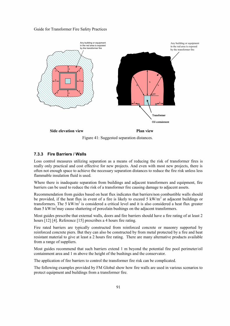
Guide for Transformer Fire Safety Practices
91
Side elevation view Plan viewFigure 41: Suggested separation distances.
7.3.3 Fire Barriers / WallsLoss control measures utilizing separation as a means of reducing the risk of transformer fires isreally only practical and cost effective for new projects. And even with most new projects, there isoften not enough space to achieve the necessary separation distances to reduce the fire risk unless lessflammable insulation fluid is used.
Where there is inadequate separation from buildings and adjacent transformers and equipment, firebarriers can be used to reduce the risk of a transformer fire causing damage to adjacent assets.
Recommendation from guides based on heat flux indicates that barriers/non combustible walls shouldbe provided, if the heat flux in event of a fire is likely to exceed 5 kW/m2 at adjacent buildings ortransformers. The 5 kW/m2 is considered a critical level and it is also considered a heat flux greaterthan 5 kW/m2may cause shattering of porcelain bushings on the adjacent transformers.
Most guides prescribe that external walls, doors and fire barriers should have a fire rating of at least 2hours [12] [4]. Reference [15] prescribes a 4 hours fire rating.
Fire rated barriers are typically constructed from reinforced concrete or masonry supported byreinforced concrete piers. But they can also be constructed by from metal protected by a fire and heatresistant material to give at least a 2 hours fire rating. There are many alternative products availablefrom a range of suppliers.
Most guides recommend that such barriers extend 1 m beyond the potential fire pool perimeter/oilcontainment area and 1 m above the height of the bushings and the conservator.
The application of fire barriers to control the transformer fire risk can be complicated.
The following examples provided by FM Global show how fire walls are used in various scenarios toprotect equipment and buildings from a transformer fire.
a
a
a
a
a
aa
a
a
a
a
a
a
aa
a
Any building or equipmentin the red area is exposedby the transformer fire
aa
bbb
60o
aa
bbb
60o
Transformer
Oil containment
Transformer
Oil containment
Any building or equipmentin the red area is exposedby the transformer fire

Guide for Transformer Fire Safety Practices
92
Figure 42 illustrates how a fire barrier is used to protect two adjacent transformers. FM Globaladvises that the fire wall should extend at least 600mm horizontally and 300 mm vertically beyondany transformer component that could be pressurized as a result of an electrical fault, including oilfilled bushings. This is represented by the distance “d” and “e” respectively.
Elevation view Plan view
Figure 42: Fire Barrier protecting two adjacent transformers.
d d
e
d d
e
2 Hour rated Fire Barrier
Transformer
Containment
2 Hour rated Fire Barrier
2 Hour rated Fire Barrier

Guide for Transformer Fire Safety Practices
93
FM Global has also defined a region downwind of a transformer where any building or equipment inthis zone will be exposed by a transformer fire. Figure 43 shows the extent of this zone. The distance“c” is dependent on the oil volume. A distance of 4.6 m applies for oil volumes less than 19,000 l anda distance of 7.6 m applies for oil volumes above 19,000 l.
Figure 43: Zone of exposure downwind of burning transformer
Figure 44 illustrates how a fire barrier can be used to protect the roof of a building located downwindof a transformer from being exposed by a transformer fire. The exposed wall of this building has 2hours fire resistance, which allows the building to be situated inside the exposed zone. However theroof of the building is now exposed. For the roof of this building to be protected from the transformerfire exposure, the exposed portion of the roof needs to be Class A (i.e. non-combustible)construction.
Figure 44: Exposed building roof downwind of burning transformer
Building60o
Building60o60o
Exposed roof areamust be Class Aconstruction
2 hour fire resistant wall
60o60o
c
Transformer
Oil containment
Transformer
Oil containment
Any building or equipmentin the red area is exposedby the transformer fire

Guide for Transformer Fire Safety Practices
94
The alternative solution is to extend the 2 hour fire resistant wall of the building as shown in Figure45 and to use the wall as a fire barrier to protect the roof. Depending on the height of the building andhow high we have to extend the wall, it is often too onerous to extend the wall beyond what would beconsidered a typical parapet height (less than 2 m).
Figure 45: Extending building wall to protect exposed roof section
It is also possible that the exposed building is much higher than the transformer. In this case, only theexposed area of the wall of the building needs to be 2 hour fire resistant. The exposed wall area canbe determined as shown in Figure 46. The horizontal and vertical distances “a” and “b” are takenfrom Table 18.
It should be noted that the vertical distance “b” is read from Table 18. It is not calculated from Figure46 (by determining the height at which the 60o line from the top edge of the exposing transformerintersects the exposed building). This is to simplify the process of determining the size of the exposedwall. The end result is more conservative.
Figure 46: Side elevation of exposed area of a tall building
Building60o
Building60o60o
Extend 2 hour fire resistant wallto protected exposed roof area
60o
Transformer
Oil containment
Building with noncombustible walls
2 hour fire barrier

Guide for Transformer Fire Safety Practices
95
Figure 47: Front elevation of exposed area of a tall building
An open top masonry sound enclosure can be a very effective fire barrier as it can contain the firewithin the enclosure. Most of the heat from the combustion will rise vertically into the air above thesound enclosure. The pictures in Figure 48 below illustrate the effectiveness of such an enclosure forfire containment. It is also interesting to note the silicone polymer insulators on the surge arresterswere only burnt on the side facing the fire. They do not sustain a fire. The only component burningoutside the enclosure is the upper half of the OIP bushing condenser which was blasted away fromthe Transformer to the outside of the sound enclosure wall, where it remained hanging, connected toa surge arrester by the flexible busbar lead.
The substation was de-energized for approximately three hours whilst the fire brigade extinguishedthe fire, but the supply could be restore quickly from the remaining two transformers as the fire wastotally contained to the transformer within the sound enclosure.
The 110 kV HV switchgear and the 33kV secondary power cables and cable terminations locatedjust outside the sound enclosure remained undamaged and serviceable. This allowed the burn outtransformer to be replaced and supply restored from the replacement transformer within 10 days.
a
b
Building with non combustible walls
2 hour fire barrier

Guide for Transformer Fire Safety Practices
96
Fire contained to 1 of 3 transformers Fire contained to within sound enclosure.Polymer SA insulators on top of enclosurewall only melted on side towards fire only.
HV Switchgear remained intact.
Aluminium busbar partly melted, but secondarycables and cable terminations intact.
Top of transformer the day after
Figure 48: Fire on 80 MVA Transformer in sound enclosure
7.3.4 Oil ContainmentsOil containment is important both from a fire risk reduction strategy and also from an environmentalprotection point of view. In this section oil containment is only discussed from the fire risk reductionand containment point of view.
The aim is to contain spilled oil to avoid a pool fire spreading to adjacent plant, structures andbuildings and also to avoid it adding to the fuel load otherwise available to the fire as well as forenvironmental protection purpose. Older installation may have used earth barriers or dams, butmodern day practice in most countries now uses an oil bunding which contains the oil either withinthe bunding or pipes it away to an oil / water separation tank or an oil tight storage pond away from

Guide for Transformer Fire Safety Practices
97
the transformer. If the oil is kept within the bund surrounding the transformer, then it is commonpractice to it store it within or below the surface of rock ballast or other form of oil containmentmedium where the oil is out of reach of the fire.
7.3.4.1 Oil BundingSeveral forms of oil bunding exist, but the most common ones consist of an oil tight concrete basewith a low 400-800 mm concrete, or oil tight masonry wall with the height determined so it cancontain all oil from sudden loss of oil following a tank rupture, plus a percentage allowance for firefighting water, if this is to be contained within the bunded area. The area of the bund should besufficient to be able to capture all oil ejected from pressure relief devices, ruptured bushing turrets,main tank, oil coolers and the conservator. It is common practice to allow for an ejection trajectory of30o from vertical from the highest point on these structures.
All cable conduits or trenches should be raised and sealed so spilled oil and fire cannot enter cablepaths to other plant items or buildings.
Several effective methods has been developed and the most effective and economic solution dependsof several local factor, land available, terrain - flat or sloping ground, proximity to water courses.Climatic conditions, (rainfall, temperature snow fall, frost, dust or sand storm) each of these and attimes other factors must be considered to determine the optimum solution for the specific sites.
7.3.4.2 Oil-Water Separation TanksA concrete bund connected to an underground oil/water separation tank, can be very effective indraining oil spilled from a ruptured tank, oil draining from the conservator due to a failed bushing,cable box due to failed cable terminations at sites with favourable terrain and climatic conditions. Arelative simple oil water separation tank with a multi baffle system can separate oil from water withdroplet size down to a 1mm diameter and still allow sufficient water to flow through the separationtank from fire fighting or sudden heavy downpour of rain and still retain the oil within the separationtank for recovery and safe disposal later. A common tank can be shared by multiple transformers.This means that the separation tank only need to be designed to hold the oil from the largesttransformers plus an additional margin of 15-20 % as a buffer for water flow.
One of the great advantages of the use of the separate oil water separation tank is that the bunded areahas a reduced size and the base can be left with an unobstructed concrete base which provided a lowmaintenance solution and a good safe surface area for maintenance work. An example of oil waterseparation tank is provided in Figure 49 below [62].
Figure 49: Example of an Oil-Water separation tank
The tank is constructed from modular large diameter concrete pipes with oil – water separationbarriers provided at approx every 2 meters This tank can separate oil from water down to 1 mmdiameter droplet size. For full details can be found in reference [62].
OUTLET
INLET

Guide for Transformer Fire Safety Practices
98
An alternative oil water separation tank design is shown in Figure 50. The tank is shown with both oiland water. As the specific gravity of oil is less than water this allow the oil on the top of the water tobe separated from the water by overflow of oil into the oil tank area.
Figure 50: Alternative Oil-Water separation system
Depending on the size of the bund or the volume oil in the transformers one or two flow lines may berequired to handle the flow of oil from a tank rupture. Each flow lines should be fitted with flame-trap at the oil bund end to ensure the fire cannot follow the oil to the oil separation tank Figure 51.
Figure 51: Oil separator installation
A variant from the underground oil separation tank is to direct the oil to a lined pond of sufficientcapacity where oil and water can be contained at a fire safe distance from the transformers. Thedisadvantage of this arrangement is that the oil water separation must still be dealt with beforepossibly contaminated runoff rainwater and any fire fighting water can be disposed into nearby watercourses.
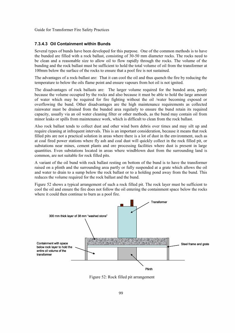
Guide for Transformer Fire Safety Practices
99
7.3.4.3 Oil Containment within BundsSeveral types of bunds have been developed for this purpose. One of the common methods is to havethe bunded are filled with a rock ballast, consisting of 30-50 mm diameter rocks. The rocks need tobe clean and a reasonable size to allow oil to flow rapidly through the rocks. The volume of thebunding and the rock ballast must be sufficient to hold the total volume of oil from the transformer at100mm below the surface of the rocks to ensure that a pool fire is not sustained.
The advantages of a rock-ballast are: That it can cool the oil and thus quench the fire by reducing thetemperature to below the oils flame point and ensure vapours from hot oil is not ignited.
The disadvantages of rock ballasts are: The larger volume required for the bunded area, partlybecause the volume occupied by the rocks and also because it must be able to hold the large amountof water which may be required for fire fighting without the oil /water becoming exposed oroverflowing the bund. Other disadvantages are the high maintenance requirements as collectedrainwater must be drained from the bunded area regularly to ensure the bund retain its requiredcapacity, usually via an oil water cleaning filter or other methods, as the bund may contain oil fromminor leaks or spills from maintenance work, which is difficult to clean from the rock ballast.
Also rock ballast tends to collect dust and other wind born debris over times and may silt up andrequire cleaning at infrequent intervals. This is an important consideration, because it means that rockfilled pits are not a practical solution in areas where there is a lot of dust in the environment, such asat coal fired power stations where fly ash and coal dust will quickly collect in the rock filled pit, orsubstations near mines, cement plants and ore processing facilities where dust is present in largequantities. Even substations located in areas where windblown dust from the surrounding land iscommon, are not suitable for rock filled pits.
A variant of the oil bund with rock ballast resting on bottom of the bund is to have the transformerraised on a plinth and the surrounding area partly or fully suspended at a grate which allows the oiland water to drain to a sump below the rock ballast or to a holding pond away from the bund. Thisreduces the volume required for the rock ballast and the bund.
Figure 52 shows a typical arrangement of such a rock filled pit. The rock layer must be sufficient tocool the oil and ensure the fire does not follow the oil entering the containment space below the rockswhere it could then continue to burn as a pool fire.
Figure 52: Rock filled pit arrangement
Transformer
Plinth
Steel frame and grate
300 mm thick layer of 38 mm “washed stone”
Containment with spacebelow rock layer to hold theentire oil volume of thetransformer
Transformer
Plinth
Steel frame and grate
300 mm thick layer of 38 mm “washed stone”
Containment with spacebelow rock layer to hold theentire oil volume of thetransformer

Guide for Transformer Fire Safety Practices
100
7.3.5 Active Fire Suppression SystemsMany forms of active fire suppression systems have been developed over time and there are too manyfor a short brochure like this to describe all these systems. The readers are therefore referred toReferences [5] [8] [9] [12] and vendor proprietary information for a fuller description of each system.The key point to remember is that when a transformer fault has developed in to an oil fire, then thetransformer is in most cases destroyed. The aim is therefore o protect adjacent asset and minimizecost of collateral damage and not to “save” the transformer. A short description of some of theavailable systems is given in the following sections.
7.3.5.1 Deluge SystemsA deluge system is a fixed fire protection system in which the pipe system is empty of water andkept pressurized with dry air, until the a fire condition is detected and the deluge valve is operated todistribute pressurized water to the nozzles or sprinklers directing the water onto the protectedobject(s). Various types of sensors can be used in the detection systems. The common ones includesensors for detection of: heat, smoke, infrared and/or ultraviolet radiation. Some common types ofdetection sensors use a low melting point material at the spray nozzles, where the melting of thesensor causes a loss of pressure in pipe downstream from the deluge valve. The loss of downstreampressure causes opening of the deluge valve and activation of the deluge system. Other types ofactivation can also be used. The dry pipe system also allows this system to be used in areas wheresub-zero temperatures occurs.
Deluge systems are typically used where quick application of large quantities of water is required tocontrol a fire and protect high value adjacent assets, such as on generator and unit transformers inpower stations, bulks supply transformers at industrial plant and major transmission or substationtransformer in city locations. The deluge system can quench a fire externally to a transformer bycooling the fire and the fuel and also by reducing the oxygen available for the combustion. It can alsocool the transformers tank, oil pipes and the cooler bank to prevent rupture form being caused by thefire and possible against explosion caused by heat from the fire. It does not prevent tank rupturecaused by internal arcing from the initiating fault. Figure 53 shows a typical water spray arrangementfor a transformer and its oil containment area in a diagrammatic presentation.
Nozzles and sprinklers must be aimed to project water across all horizontal and vertical areas to beprotected, but not aimed directly at bushings. As this could possible cause flashover, or crack andrupture of bushings by thermal shock, not only during a fire, but also if the system is tested whilst thetransformer remains energised.
A deluge system can also be effective for cooling adjacent structures and building surfaces to preventdeformation, structural collapse and the spread of the fire.
Foam can be added to a water deluge system. In such systems an air- or water-foam concentrate isintroduced into the deluge water at a controlled rate. Foam water systems are used to control and/orextinguish fires, which require both smothering and a cooling agent. It can be effective ontransformer fires as it can cover horizontal surfaces such as the top of the transformer and the bundfloor area where it reduces the risk of a pool fire. It also adheres better to vertical surfaces than purewater. The disadvantage of foam is that the fire fighting water is contaminated with the foamingagent and may require decontamination before it can be released to the drains or nearby streams.

Guide for Transformer Fire Safety Practices
101
Figure 53: Typical water spray arrangement for transformer and oil containment area
Deluge system requires a large volume of water NFPA guidelines states 10.2 l/minute/m2 for adeluge system for transformer fire protection. This means that the water must be available and thedelivery system must be designed to deliver this quantity at the required pressure. The drainage/oilseparation system must also be able to handle the large flow of water from such a system. However,it may be possible to reclaim and re-use of the water for ongoing fire fighting, if an effective oil-water separation system has been implemented as part of the design.
Figure 54: Water spray system with rock filled pit
Figure 54 shows a water spray system being tested on a transformer. Note that that there is no waterspray protected directly onto the rock filled pit. This is not necessary as long as the pit has enough

Guide for Transformer Fire Safety Practices
102
volume to contain any spilled oil and the fire fighting water well below the rock surface. Thereduced flow volume of water will assist in this objective.
Cable insulation is considered to be the source of fuel and propagates the fire. Cable trays and cablerun to and from the transformer must therefore also be included for protection by the deluge system.
To be effective a deluge system must be designed by design engineers, who have specific expertise insuch systems.
7.3.5.2 Water Mist SystemsWater Mist is also an efficient fire-fighting medium. The difference between Water Mist and atraditional water based fire fighting systems is that the Water Mist systems require much less water asthey uses have smaller water droplet (typically only 0.025 to 0.25mm dia. for high pressure watermist systems).
As heat absorption is a function of surface area and not volume, smaller droplets mean more surfacearea are available and therefore faster heat absorption for same quantity of water or equal heatabsorption with much less water. When a droplet of water vaporises to steam, it expands by approx1,600 times. Water mist is quickly converted to steam that smothers the fire and prevents furtheroxygen from reaching it. At the same time, the evaporation creates a significant cooling effect ofcombustion gases and blocks the transfer of radiant heat.
Water Mist combines the fire suppression properties of both conventional water-based deluge orsprinkler systems and gaseous fire suppression systems.
Water mist is available in both as low and high pressure systems. However for fire protection ontransformers the high pressure system should be used as this is considered suitable for protection ofmachine containing Class B flammable liquid.
7.3.5.3 Water CurtainWater spray protection with water curtain fire protection for adjacent transformer, is a high watervolume water spray system where water is also sprayed in a narrow line between closely spacedobjects as well as onto the object on fire. It is therefore especially suitable for fire protection ofadjacent units of single phase transformer used to form a three phase banks. Fig.55 shows two banksof three single phase transformers protected by water curtain spray system between adjacenttransformers.
Figure 55: Water curtain protection in Japan

Guide for Transformer Fire Safety Practices
103
A critical part of the design of Water Curtain protection is that there must be sufficient wateravailable to maintain the required flow rate for the duration the protection is required. Where thereare multiple transformers installed adjacent to each another, the water spray system needs to bedesigned for the simultaneous operation of the exposing transformer as well as all exposedtransformers. For example, in a bank of six single phase transformers that are arranged in a row, itneeds to be designed for the simultaneous operation of the water spray systems on at least threetransformers, the one on fire and the two adjacent transformers.
7.3.5.4 Hypoxic EnclosureBackground. As previously stated oxygen is (among other factors) needed to start and sustain a fire.The oxygen dissolved in the insulation liquid is not accessible for a fire. Even if the gas analysis says30,000 ppm oxygen in the oil, this is not a fire risk.
The solution to keep oxygen away from the origin of a fire has in the past successfully used carbondioxide, halon, nitrogen and other gases. The disadvantage for all of these has been that humanbeings could be suffocated and for halon its environmental impact when release to the atmosphere.
It has been shown that there is oxygen concentrations in air, which prevents fire and still allows allowhuman to breathe.
Only a slight decrease of the oxygen concentration in air decreases the fire intensity and at 16 %oxygen in the air there is no risk of a fire. One mean to avoid a fire in an oil filled transformer wouldbe to ensure the air surrounding the transformer has an oxygen content of less than 16 %. It wouldthen be 100 % fire proof. Humans can continue to work in oxygen concentrations as low as 14-13%although with reduced work output. And can survive in air with concentration in the oxygen evenbelow 10 %. However, when the air has an oxygen content of less than 17 % it is called hypoxic andthere should be some time restraints on working in hypoxic air because the haemoglobin cannot notcarry its full amount of oxygen. Fig. 56 shows graphs for fire intensity and haemoglobin as a functionof oxygen content in air.
Figure 56: Oxygen percentage effect on fire intensity and haemoglobin saturation

Guide for Transformer Fire Safety Practices
104
7.3.5.5 Fire Suppression using Inert Gas for Oxygen DisplacementCompared with water spray system, gas injection system has advantages such as reducing civil workat installation, no necessity of securing water, reducing piping installation, and so on. It should benoted that for an Inert Gas for Oxygen Displacement or a Hypoxic enclosure to provide effective fireprotection, the enclosure must remain intact. So pressure venting may be required to ensure that theenclosure is not breached by the transformer failure event.
Gas injection systems have in the past been using CO2 or halon, but these gases have potential ofattack to ozone layer and also have physiological influences. So today, from the view point of theglobal environmental protection and safety for human beings, the inert gas applied for fire protectionof power transformers is now mainly nitrogen and also sometimes a mixture gas of Nitrogen, Argon,and CO2, Nitrogen is a cost effective and readily available gas.
As an example, when nitrogen gas is discharged to extinguish a fire, the concentration of nitrogen gasand oxygen gas in the room will charge to about 87% (normally 78%) and 12.5% (normally 21%) byvolume respectively, according a supplies data. This means that oxygen concentration can be reducedfrom 21% to 12.5% within 1 minute after start of discharge. Continuous combustion requires morethan 15% of oxygen concentration by volume, so the above data shows that the gas mixture as statedabove is effective for fire suppression.
For application on power transformers where sound insulation panels are installed the panelenclosure can be used as outer enclosure for the gas containment for the fire suppression.
It is required than any ventilation provided on the sound enclosure if fitted with dampers whichcloses during the gas injection and remains closed until the fire extinguishing is completed.
If there is no sound insulation enclosure, then an additional enclosure will be necessary.
Figure 57 shows a diagrammatic presentation of a gas protection system.

Guide for Transformer Fire Safety Practices
105
Figure 57: Transformer sound enclosure with Nitrogen gas fire protection
Figure 58 shows a photo of a two transformer installation in with sound enclosure panels andNitrogen fire suppression system. The Inert gas cylinders are installed outside the sound insulationpanel and can be located near transformer, then length of piping can be minimized.
Inert gas is injected into the enclosure by smoke detection signal and transformer fault detectionsignal. Selection and combination of trigger signal depends upon each user’s practice and they areformed AND gate circuit for alarm evacuation. Transformer fault detection signal can be pressurerelief device or Buchholz Relay.

Guide for Transformer Fire Safety Practices
106
Figure 58: Fire Suppression system using inert gas on transformersinstalled within sound enclosure panels
7.3.6 Indoor City SubstationsIndoor city substations have many more aspects which need to consider from a safety point of viewthan is applicable for conventional outdoor substations located in areas with low population density.For indoor city substations human safety is paramount and if the probability of a transformer firecannot be totally eliminated, then it must be reduced to an extremely low probability. This isespecially so where a major city substation are located in the basement of a high rise office tower orwith residential or business properties located wall to wall with the substation on a busy street withpedestrian traffic in front of the building.
The design of city substations are complex and each site must be studied and assessed on a case bycase basis. It is beyond this document to address all the issues which must be considered for suchinstallations.
Chapter 6: of this document discussed steps available to mitigate the risk of the transformer causing afire, these steps are still applicable to indoor substations.
In this section we will discuss the consideration and key preventative measures which must be takeninto account to prevent a fire spreading and endangering human life and adjacent assets from a firespreading in the event a transformer failure occurs.
For this purpose we will discuss the key considerations and then present two alternative examples forcity substation installations:
one installation using mineral oil insulated/cooled transformers

Guide for Transformer Fire Safety Practices
107
the other using SF6 insulated/cooled transformers
The concepts and issues to be addressed for the two type of installation are quite different.
7.3.6.1 Key Considerations for City SubstationsThe keys issues of concern discuss are mainly, - but not solely from a Fire Safety Point of view.
Proximity to other buildings and consequences of transformer explosion and fire, but alsoemission of hot air, noise and the need for access for delivery and installation of thetransformers, other major equipment and its ongoing maintenance
Pedestrian walkway beside substation, explosion and fire risk, (but also noise, hot air,installation and maintenance access)
Community perceptions concerning probability and risk of transformer fires
The indoor substation itself – explosion and fire risk to the building
Containment oil and/or gases from major failure
Containment oil and/or gases from minor leaks, including possible fumes from such leaks
Provide oil and water retention systems to contain oil and foam contaminated fire fightingwater.
Prominence and special “value” of adjacent buildings and environment, uniqueness, heritage,river, etc
Future building above substation – fire, noise, vibration, hot air, maintenance
Aesthetics presentation and fit in with neighbourhood and street scape
The design of the building will need to take into consideration:
The use of non-flammable or low flammability materials in the design of the transformersand in the substation building generally.
Segregation and layout of transformers
Fire and explosion protection for building
Pressure release of oil and combustible gases following explosive failure
Retention oil and water following a failure and fire
Possible leakage or sudden release of gas from a gas insulated transformer
Segregation and layout of the transformers and (reactors and capacitor banks whereapplicable) to mitigate the consequences of an explosion and fire.
Choice of cable types and cable terminations and non combustible sheating materials orcoatings
Fire detection and fire fighting equipment
Oil delivery, storage and processing during installation and future maintenance
Incorporate fire and blast protection for the building itself and adjacent public areas andcommercial developments, if an explosive failure is possible

Guide for Transformer Fire Safety Practices
108
Access for delivery of plant during construction and the subsequent maintenance
Some of these the issues are very dependent on the choice of the transformer design and theinsulation/cooling medium used in the transformer.
To illustrate the concept and design consideration for city substations it has been decided to provide aseries of diagrams, sketches and photos which illustrate the concepts and then discuss the key the keypoints with reference these depictions.
7.3.6.2 City Substations Using Oil Insulated/Cooled TransformersThe illustrations in Figure 59 below have been provided by the member of the working group fromRTE France. The illustrations are from substations located in Paris.
The most critical aspect for an indoor city substation with oil insulated transformers from a fire safetypoint of view is to avoid a transformer oil fire. In the substation designs depicted above this has beendone by use of:
Cables with dry insulation only
SF6 insulated cable terminations and SF6 to oil bushings to minimize risk of a cabletermination bushing failure initiating a fire.
The oil capture and bunding has been arranged to capture a large quantity of oil and cool it bypassing it through a rock ballast grate and directing it safely away from the building.

Guide for Transformer Fire Safety Practices
109
Exterior View. As can be seen from the picturethe substation blends in well with the street-scape, with the only noticeable difference beingthe fairly wide access door
Internal arrangement of transformer andtransformer ancillaries. Note Gas insulatedbushings and cable terminations and stone grateover oil capture sump.
Schematic elevation view of oil sump with oilwater separator.
Elevation view of arrangement for thetransformer section of the substation.
Figure 59: Internal design of a city substation with fire protection consideration
7.3.6.3 City Substations Using SF6 Insulated/Cooled TransformersThe illustrations used for the SF6 Gas insulated substation 330/132 kV has been copied from a paperand presentation material listed as Reference [63] which provides much more details of thebackground and choice of design than is listed in this Technical Brochure.

Guide for Transformer Fire Safety Practices
110
The key differences between a City indoor substation using oil filled transformer and a substationusing SF6 insulated transformer and, switchgear and cable terminations are :
There is no oil and SF6 is non combustible.
The SF6 transformers and switchgear are virtually explosion proof and even if any of theseshould rupture or develop a leak, then they would only release a non-combustible gas.
Combustible material used in the building can be kept to a minimum which leaves very littleto cause or sustain a fire.
Control cables and power cables up to and including 132 kV cables can be chosen with drycable insulation.
Cable sheeting can be non-flame propagating or painted with a non-flame propagatingcoating.
This means that the fire risk can be virtually nonexistent and the fire protection can be keptto a minimum and no more than required for a standard commercial or residential building.
The capital cost of large SF6 insulated transformers is substantial higher than the cost of oilfilled transformer. But the substantial savings on building cost and fire risk reductionmeasures will to a large extent, if not fully offset the higher capital cost of the SF6 insulatedtransformers and is probably the only solution with a virtual nil fire risk transformer.
This then raises the question why with all the virtues of virtual nil fire risks, why is not all indoor citysubstations using SF6 insulated transformers. The most like cause is probably, that SF6 is not anenvironment friendly gas. Many potential users have severe concern with its potential impact on theenvironment if spilled or otherwise released into the environment.
Some of the key consideration from a fire safety point of view listed in [63] are:
Close to other buildings – noise, hot air, explosion and fire risk, maintenance
Close to Darling Harbour – oil containment
Indoor substation – explosion and fire risk to building
Pedestrian walkway beside substation – noise, hot air, fire
Future building above substation – noise, vibration, hot air, fire, maintenance
Community perceptions concerning transformer fires
Depending on transformer design, there is a need to consider:
Segregation and layout of transformers
Fire detection and fire fighting equipment
Fire and explosion protection for building
Pressure release and combustible gases following explosive failure
Oil and water retention following failure and fire
Access for maintenance

Guide for Transformer Fire Safety Practices
111
Underground City substation in Sydney with3 x 400 MVA 330/132/11 kV Transformers
External view Cut through elevation view
Figure 60: SF6 underground substation in Sydney [63]
The choice of SF6 insulated transformers solved or reduced the complexity of these design issuessubstantially:
Because of the SF6 transformers, only smoke detectors and water sprinklers are used -standard building design practice.
All 132kV connections with solid insulation cables to GIS.
330kV cables have paper oil insulation, but are within substation buried in a sand/cement ix.
330kV cables are connected to GIS in building basement.

Guide for Transformer Fire Safety Practices
112
Fire proof coating on major control cable runs.
The SF6 designs for main transformers and reactor have removed the risks of fire andexplosion
There is no risk of oil leakage into Darling Harbour.
The containment and collection of SF6 gas can be achieved with a reasonably simple buildingdesign.
The SF6 designs have allowed a significantly simpler and cheaper building design than oilinsulated designs.
Minimal fire protection systems apart from standard building requirements.
7.4 Underground SubstationsFire Protection for Underground substation are complex and varies significantly between the types ofunderground substation and therefore must be assessed on a case by case basis and this documentcan only address some of the basis considerations.
However, the common requirement for all underground substations is to reduce the fire risk to a verylow risk value. This is true whether it is a mining shaft, a power generation station, or a distributionsubstation.
The following measures are considered by various industries as best practices in terms ofimplementing fire risk management for underground substations using oil filled power transformers.
The transformers are located on their specific transformer hall which is isolated from theother important assets, like generators and turbines hall and also from buildings/chambersoften occupied by people.
Each of the power transformers is located in its specific bay, which has fire and blast wallson either side.
Where is there a number of power transformer, say exceeding three, it is recommended tofurther subdivide the transformer hall e.g. two units on the left and two units on the right ofthe access tunnel if there were four transformers. The main access tunnel will then runbetween these transformer groups.
Transformers are normally fitted with the emulsifier system or other oxygen exclusionsystem which enables automatic fire fighting. In addition to these protection deluge or watermist or water based foam system may also be installed to contain and extinguish any fire inthe wider area around the transformer.
The oil catchment and containment areas must be such that it is not possible for a burning oilto flow pass the other areas.
The fire/flame detectors are usually positioned at several locations near the transformers andwithin the transformer hall.
Like in ground level installations, the transformer bays are equipped by a bund wall whichcontains oil spills. The spilled oil will then be channelled into an oil catchment area where itis contained.
The air conditioning system must be linked to the fire protection system and must switch offwhen fire is detected in the area.

Guide for Transformer Fire Safety Practices
113
The main access doors at the tunnel opening and the transformer hall must be closed shut toprovide some containment from the transformer hall.
Personnel have to have an escape route located alongside the lifts which is far away from thetransformer hall side.
7.5 Highest Impact Strategies(The following is from an industrial insurer’s point of view)
7.5.1 Outdoor SubstationsThe following passive loss control alternatives are recommended for reducing the risk associatedwith transformer fires:
Physical Separation
The main hazard associated with mineral oil filled transformers is the severe fire exposure presentedby a high heat release, long burning oil pool fire. The most effective means of controlling thisexposure is by separating important buildings and equipment from burning transformers.
Fire barriers
It should be noted that fire barriers used to control transformer fire risk do not need to be blast walls.The pressure exerted on the fire barriers during a transformer explosion is no higher than the normalwind load the fire barrier has to withstand. This is always true as long as the transformer is notenclosed on all sides.
Since fire barriers for transformer exposure protection only need to be 2 hour fire resistantconstruction, no special foundations or reinforcement are needed to install these fire barriers. This hasgiven rise to a growing market for lightweight, modular fire barrier products. These products make itcheap and quick to install fire barriers and also allow the fire barriers to be removed for maintenanceaccess.
Rock filled pits
Another passive loss control measure against transformer fires is the use of rock filled pits to containas well as extinguish the oil pool fire from a transformer failure.
Water spray system
Where passive fire protection solutions are not practical or cost effective, a water spray systemdesigned to provide 12 mm/min over the transformer surfaces and 8 mm/min over the oilcontainment area can be used to control the transformer oil fire and prevent it from exposing otherequipment and buildings.
7.5.2 Indoor SubstationsThe insurer also recommends the following passive methods for reducing the fire risk associated withmineral oil filled indoor transformers:
Elimination or reduction of the hazard
It is possible to eliminate or reduce the fire risk associated with an indoor transformer fire by utilizingdry type, gas insulated, FM Approved or equivalent, and silicone filled transformers. These low firerisk transformers were discussed in the previous section for outdoor transformers.

Guide for Transformer Fire Safety Practices
114
Three hour fire resistant construction
Where it is not practical or cost effective to utilize low fire risk transformers, the exposure presentedby indoor mineral oil filled transformers to the rest of the building can be controlled by housing thetransformer in a three hour fire rated area. This area has to be liquid tight to prevent burning oil fromflowing outside the cut-off area.
Where multiple transformers are located in the fire cut-off area, each transformer should be locatedwithin its own three hour fire rated room.
It is also good practice to locate the fire rated area along an outside wall of the building and on theground floor where practical. This will facilitate manual fire fighting efforts, minimize the fireexposure to the rest of the building and make it less onerous to achieve the required three hour firerating.
Reference [12] recommends the following combination of active and passive methods for reducingthe fire risk associated with mineral oil filled indoor transformers:
One hour fire resistant construction with automatic fire protection
It is not always practical or cost effective to construct a three hour fire rated room to contain theexposure presented by indoor mineral oil filled transformers. In these cases, automatic fire protectioncan be used to reduce the fire rating of the room. The automatic fire protection options are:
Carbon dioxide extinguishing systems Water mist systems designed for machinery spaces Sprinkler systems (designed for a density of 12 mm/min over the entire fire area)
Where multiple transformers are located in the fire cut-off area, automatic fire protection designed toprotect the entire cut-off area can be used in lieu of locating each transformer it is own separate cutoff area.
A unique hazard associated with indoor oil filled transformer is the non-thermal damage exposureto equipment in the building where the transformer is housed. For example electronic relay and DCSequipment in substation and power station equipment rooms, or power electronics in the valve hall ofHVDC substations. Where this exposure exists, steps should be taken to mitigate this exposure.These steps normally include the provision of a mechanical ventilation system, venting to an area thatdoes not expose the occupancy and should be supplied from a power source that will not be affectedby the transformer fire.

Guide for Transformer Fire Safety Practices
115
Chapter 8: Plans for a Fire Event
8.1 The Importance of Planning for a Fire EventThe earlier chapters of this report provide advice for preventing or reducing the risk of transformerfires. Solutions for controlling the damage caused by transformer fires were also presented.
However, even with the best loss prevention and control measures in place, without a propercontingency plan the damage and business impact caused by a transformer fire can still be significant.
A study [68] conducted by a large property insurer analyzed 100 random losses. Of these losses, 54had some amount of contingency planning in place prior to the loss. The average cost of these 54losses was US$7.1 million. Where contingency plans were poorly developed the average cost wasUS$7.9 million. However, where proper contingency plans were available, the average cost droppedto US$4 million – a 51% reduction in the loss cost.
Average Loss Cost(Some Contingency Planning
Average Loss Cost(Inadequate Contingency Planning
Average Loss Cost(Good Contingency Planning
Figure 61: Loss analyzed for contingency planning (Average loss totals in US$ Millions)
This study shows not just the importance of contingency planning in reducing the impact of a loss,but also the importance of having a properly developed contingency plan in place. Very often,companies view contingency planning as a paper exercise and falsely believe that they have propercontingency plans in place after developing an emergency response procedure and posting theprocedure for its staff to read.
8.2 Contingency PlanningGood contingency planning should consist of three separate plans:
An Emergency Response Plan (immediate to short term mitigation)
A Disaster Recovery Plan (short to medium term mitigation)
A Business Continuity Plan (short to long term mitigation)
Because contingency planning is very much influenced by local conditions, it is not possible toprovide a definitive guide to proper contingency planning. This chapter provides general guidelinesfor developing an effective contingency plan with a special focus on managing transformer fireevents.

Guide for Transformer Fire Safety Practices
116
Additional reading on contingency planning can be found in References [23] [24] [64] [65] [66] and[67].
8.3 Emergency Response PlanThe Emergency Response Plan is the initial “reaction” to an incident. This plan focuses on how localpersonnel respond to an event in the minutes to hours following an incident.
The objectives of the Emergency Response Plan are:
Personnel safety Damage containment Damage assessment
Emergency Response Plans are very critical. How well local personnel react to a fire event oftendetermines the size of the loss.
A study [68] by a large property insurer where 1,341 losses were analyzed over a recent 10 yearperiod showed that where emergency response was effective, the average loss cost was US$1.3million, compared to an average loss cost of US$5.3 million where emergency response wasineffective.
Figure 62: The impact of effective emergency response
8.3.1 Emergency Response PolicyThe Emergency Response Plan should be formalised by developing a policy that is supported bysenior levels of management. The policy should include the following sections:
A Purpose section to declare the company’s intent and objectives. It should also specify limitations tothe response to certain site-specific incidents. For example, the policy may state that it is thecompany’s decision not to fight certain types of fires. Instead, only defensive action would beprovided until the public fire service arrives.
A Policy section to outline the emergency response plan and to state executive management’scommitment to the emergency response plan. The policy should be reviewed at least annually toensure that changing conditions are included and kept up to date.
A Responsibility section to designate the persons responsible for generating and maintaining theemergency response plan.
Having an Emergency Response Policy in place communicates the importance of the EmergencyResponse Plan to employees and lets the Emergency Response Team know that their role is

Guide for Transformer Fire Safety Practices
117
considered to be critical to the company’s ability to handle and recover from emergencies anddisasters.
8.3.2 Members of the Emergency Response TeamStaffing the Emergency Response Team (ERT) will depend on local conditions. Large generatingstations typically maintain fully staffed ERTs. These dedicated teams may not be feasible whendealing with remote unmanned facilities. This limitation has to be recognised and taken into accountby the company when developing the Emergency Response Policy. For example the recognition thatit is not practical to maintain a fully staffed ERT may result in a risk management decision to applyonly passive means of fire control to manage transformer fires and to rely entirely on the localauthority Fire Department to manage the fire. This is likely to result in higher business impacts and isa risk that the company must accept.
Table 20 gives a generic list of the members of a typical ERT. The responsibilities of each member ofthe team have also been described as it relates to a transformer fire event.
The ERT Leader is a key member of the Emergency Response Team.
In addition to their responsibilities during an emergency, the ERT Leader is also responsible for thefollowing:
Develops a Pre-Incident Plan with the Fire Department (please see Chapter 8.3.3 below).
Organises regular familiarisation visits to the substation for members of the Fire Department.
Develops step by step response procedures for handling transformer fire events as well asother emergencies.
Co-ordinates regular training for the ERT members and involves the Fire Department inemergency response exercises.
Audits and updates the emergency response procedures and the emergency response policyregularly, especially when there have been any changes in either the substation or thecompany’s operating practices.

Guide for Transformer Fire Safety Practices
118
Table 20: Responsibilities of the Emergency Response Team
Position Responsibilities
ERT Leader Directs the ERT actions during an emergency. Co-ordinates with Emergency Services personnel. Communicates with the Disaster Recovery Team and senior management. Ensures that material required by the ERT such as hoses, foam concentrate,
spill containment kits, breathing apparatus, radios and torches areavailable.
Notifier. Ensures that the emergency services are properly notified of the event. Notifies ERT members of the emergency. Ensures that the ERT is properly staffed and arranges for alternates when
necessary.
Fire protectionsystemoperator
Has a full understanding of the fire protection system and makes sure thatthe fire protection system is operating correctly during the fire event.
Ensures that the control valves supplying the fire protection systems at thefire area remain open until instructed otherwise by the ERT Leader or theEmergency Services Leader.
Fire pumpoperator
Has a full understanding of how to operate the fire pump. Checks that the fire pump has started in a fire event and is able to start the
pump manually if needed. Ensures the fire pump stays running until instructed otherwise by the ERT
Leader or the Emergency Services Leader.
Fire fightingteam
Depending on the level of training and expertise, the ERT’s fire fightingteam may carry out significant manual fire fighting efforts in support of theFire Department.
In most cases the fire fighting team is only equipped and trained to carryout basic fire fighting using fire extinguishers and small hose lines.
Switchingpersonnel
These are key members of the ERT because they carry out switchingoperations to make the substation safe for the ERT fire fighting team andthe Fire Department.
Supportpersonnel
Depending on the local conditions, support personnel may include fitterswhose role is check that oil containment, oil separation and oil drainagesystems are functioning properly.
They may also be responsible for setting up temporary lights andbarricades to assist the ERT fire fighting team and the Fire Departmentwith their fire fighting efforts.
Salvage team A salvage team may be needed if the fire event is expected to exposenearby equipment and buildings.
The salvage team may take steps such as salvaging important documentsfrom exposed buildings, moving exposed equipment away or protectingequipment from fire-fighting water or foam.
Evacuationco-ordinator
The evacuation co-ordinator makes sure that all personnel have been safelyevacuated and accounted for.

Guide for Transformer Fire Safety Practices
119
8.3.3 Pre-Incident Planning with Emergency ServicesA key component of an effective Emergency Response Plan is pre-incident planning with EmergencyServices, in particular the Fire Department. It is a widely held misconception that because fire-fighters are trained to fight fires, the Fire Department will be able to handle a transformer fire.However, fighting a transformer fire is a something that most fire departments are not trained tohandle, especially volunteer Fire Departments that are most likely to respond to a transformer fire at arural substation.
Even professional metropolitan Fire Departments consider transformer fires in electrical substationsto be a special challenge for the following reasons:
Risk of electrocution: Fire Departments will generally not attempt any fire fighting efforts untilthey are assured that the electrical hazards have been removed and it is safe to enter thesubstation. If there is no emergency response plan in place, there may not be any person that cangive this assurance to the Fire Department.
Unfamiliarity with fire fighting capabilities: Electrical Substations are usually not supplied bythe public water supply and will often have their own fire fighting systems. Unless the FireDepartment is familiar with these fire fighting systems, they are unlikely to utilise any of thesubstation’s fire fighting systems to fight a fire. The Fire Department may also choose to isolatethe substation’s fire protection system if they are unsure about its operation.
Hazardous Materials: The Fire Department usually need to be aware of all hazardous materialspresent on site before they will commence fire fighting efforts. Without this knowledge the FireDepartment may not even be willing to apply water to the fire in case there are materials in thesubstation that may react dangerously with water.
Security: Electrical substations are often high security areas that are deliberately poorly signposted.If the Fire Department does not know the location of the electrical substation, they may not be able torespond in a timely manner. The Fire Department will also be reluctant to enter the fenced perimeterof a substation if there is no-one available to grant them access and to assure them of safe workingclearances to live electrical equipment.
Because of these special challenges, it is important to involve the Fire Department in thedevelopment of the Emergency Response Plan. In particular, the ERT leader should develop anIncident Command System with the Incident Commander of the Fire Department where the roles ofthe Fire Department and the ERT are clearly defined. The Fire Department and the ERT should workas a team to handle any emergency at the substation.
The Fire Department should also be taken on a regular familiarisation tours of the substation so thatthey are aware of all the special conditions that would affect their fire fighting efforts. Thesubstation’s fire protection systems should be explained to the Fire Department so that the FireDepartment is aware that of the fire control philosophy adopted by the substation. For example, thesubstation may use fire walls or water spray systems to contain a transformer fire to the affected unit.This approach means that the Fire Department no longer has to apply water on adjacent equipment orbuildings to prevent fire spread. This would significantly reduce any damage caused by fire fightingefforts and would also reduce the urgency with which the Fire Department needs to respond to a fireat the substation. This may allow for a controlled shutdown of the substation with minimal customerimpact.
Familiarisation tours of the substation will also allow the Fire Department to develop a HazardousMaterials Response plan so that their Hazardous Material team is aware of the actions that need to betaken during a substation fire. The Fire Department should also be involved in the development of theEmergency Response Procedures. And wherever possible, joint exercises should be conducted with

Guide for Transformer Fire Safety Practices
120
the ERT team and the Fire Department in-order to understand and test the inter-relationship of eachgroup’s reaction to various emergency scenarios.
Figure 63: Situation where no Emergency Response Plan was in place.
Figure 63 above shows the consequence of a transformer fire where no Emergency Response Planwas in place. The fire was reported to the Fire Department by the public. And when the FireDepartment arrived, there was no utility personnel present to co-ordinate fire fighting efforts or togive the Fire Department access to the substation. The Fire Department ended up fighting the firefrom outside the substation fence. Fire fighting efforts had minimal impact on this loss.
8.4 Disaster Recovery PlanThe Disaster Recovery Plan is the ongoing process of disaster mitigation. The objectives of theDisaster Recovery Plan are to expedite the following actions:
Damage assessment Damage control Recovering business operations
Whereas ERT members are selected from local personnel, the Disaster Recovery Team (DRT) shouldbe comprised of members with senior management roles and having a high level of decision makingauthority.
This is necessary because the DRT may need to make decisions that place the company at anincreased risk in order to expedite the recovery from a transformer fire. These actions may includeoperating the electrical system at a reduced state of reliability, altering protection relay settings suchthat the system is at a reduced level of protection, or operating equipment at above their nameplateratings. The DRT may also need to engage contractors and authorise large sums of expenditure toexpedite damage control and business recovery activities such as authorising the use of mobilesubstations, rental transformers, and emergency generation to restore power to customers affected bythe transformer fire.

Guide for Transformer Fire Safety Practices
121
In the same way that local conditions play a large part in the make-up of the ERT, it is also notpossible to exactly define how the DRT should be staffed. However, an effective DRT should includethe following roles as a minimum:
Table 21 : Responsibilities of the Disaster Recovery Team
Role Responsibility
A crisis or incidentmanagement team
Strategic decision making and communication withexecutive management and other high level stakeholders.
Expediting the recovery of operations to pre-incidentconditions.
A site disaster recoveryteam
Early damage assessment. To provide advice to the crisis management team on
different damage control actions as well as options forexpediting recovery to pre-incident conditions.
Communication and liaison with Emergency Services aswell as other authorities such as the Environment ProtectionAgency.
A media spokesperson To provide a positive commentary to the public, companystaff, customers and other stakeholders about the disaster.
An insurance companyliaison
Works with the insurance company to report the loss and totrack the costs associated with expediting recovery to pre-incident conditions.
Utilise the insurance company’s resources to help thecompany recover quickly from the transformer fire.
Although the importance of the Crisis Management Team and the Site Disaster Recovery Team isself evident, the role of a Media Spokesperson should not be overlooked. A transformer fire is ahighly public event and if the news of this event is not properly managed, the public image andreputation of the company may be adversely affected. This could in turn translate to a loss of marketvalue and market share. Negative public sentiment could also impede the company’s efforts torecover quickly from this event.
The role of the Insurance Company Liaison should also not be overlooked. Involvement of theinsurance company as early as possible will ensure a quick recovery to normal operations. It is oftenin the insurance company’s interest for their clients to recover as quickly as possible from a disasterand the insurance company may be able to help expedite recovery by offering to pay for contractorsthat can help with clean up, decontamination, forensic investigation and repairs. Because of their pastexperience with similar losses, the insurance company often has good access to contractors whospecialise in business recovery activities. This makes the insurance company a good resource to helpwith business recovery strategies.
One other key responsibility of the DRT that has not been discussed is the decision to invoke thecompany’s Business Continuity Plan.

Guide for Transformer Fire Safety Practices
122
8.5 Business Continuity PlanIt is beyond the scope of this document to provide detailed guidance on Business Continuity Plans.These are business continuity strategies developed at executive management level to recover from adisaster as quickly as possible while addressing the impact of the disaster to its customers andpreserving the company’s market value.
For a transformer fire event, the business continuity strategies include the contingency plans fordealing with severe transformer failures such as:
Entering into an agreement with transformer manufacturers to maintain a manufacturingslot that can be used in an emergency to expedite the delivery of a replacementtransformer.
Entering into a transformer leasing program with transformer manufacturers where themanufacturer commits to providing spare transformers in an emergency.
Purchasing replacement transformers from competitors or from the used equipmentmarket.
Re-directing transformers currently being built for another substation or project toreplace the failed transformer.
Expediting the manufacture of a replacement transformer by paying additional costs tothe manufacturer.
Expediting the delivery of a replacement transformer by arranging for air transportation. Maintaining an inventory of spare transformers. Drafting transportation plans to move transformers.
To be effective, these business continuity strategies need to be developed, implemented anddocumented before an emergency occurs. These strategies should also be regularly reviewed andupdated to ensure that all assumptions made are still correct.
8.6 SummaryIt is the responsibility of the management to ensure that good loss prevention and control measuresare in place to manage the risk of a transformer fire.

Guide for Transformer Fire Safety Practices
123
Chapter 9: Conclusions and Recommendations
9.1 GeneralThe conclusions for this brochure are divided into two parts: Actions to avoid a transformer fire andactions to mitigate the damage of a transformer fire that has already started.
The probability of a transformer causing a fire is low (reported typically 0.01-0.4 %), but notnegligible and the consequences can be very severe if it does occur. The aim of this brochure is topromote “Good Fire Safety Practices”. However it is recognized that whilst it is possible to reducethe probability of a transformer failure causes a transformer fire significantly, it is not possible toeliminate the risk of transformer fires totally.
9.2 Actions to Avoid a FireTo avoid a fire the fire triangle shown in Section 2.1, provides a very good graphic representation ofwhat is required to initiate and maintain a fire and therefore also how a fire can be prevented orextinguished.
Without oxygen there will be no fire. Without heat there will be no fire. Without fuel there will be no fire.
A general recommendation is to reduce the probability of in-service failures and consequently theprobability of a transformer failure causing a fire.
9.2.1 Electrical ProtectionEnsure the transformers have fast, good quality, duplicate protection and preferably 2 cycle circuitbreakers. This will reduce the impact of through faults and minimise the arcing energy withintransformer if an internal failure does occur.
9.2.2 BushingsOil Impregnated Paper [OIP] bushings are the single largest cause of transformer fires. The risk offires being initiated by a failure of a Resin Impregnated Paper [RIP] bushing or a Synthetic ResinBonded Paper [SRBP] bushing is significantly lower than for OIP bushings.
9.2.3 Cable Boxes and TerminationsCable termination failures in air or oil filled cable boxes are the second largest cause for transformerfires. It is recommended that cable termination inside a cable box is avoided wherever practical to doso, and the cable termination be made at a cable termination pot head and the connection to thetransformer be made via rigid or flexible busbar connections. Alternatively, use of plug-in type cableconnections is recommended.
Where termination of the cables in a cable box is the only practical solution, then special precautionsshould be taken to minimise the risk of an explosive failure of the cable box from arcing within thecable box.
Air insulated cable boxes:
It is strongly recommended that all air insulated cable boxes be fitted with pressure relief ventingwith a venting capacity similar to that used on medium and high voltage metal clad switchgear. Thepressure vent should be designed to open well below the rupture withstand capability of the cablebox.

Guide for Transformer Fire Safety Practices
124
Oil insulated cable boxes:
The safest design for oil filled cable boxes is a single phase cylindrical design raising vertical, withbottom cable entry and a large rupture disc discs or PRV mounted at the top cover of the cable box.Cable box should be designed so the top cover is the weakest point of the cable box so if a ruptureoccurs then it is at the top cover of the cable box and the arcing products are vented safely.
The cable box oil supply should not be connected to the main tank or the main conservator as this cancause release of a large volume oil feeding a fire. It would be better to design the cable box with anair or nitrogen cushion at the top part of the cable box or provide a separate small commonconservator for the three cable boxes.
The air / nitrogen cushion design has the benefit of reducing the pressure gradient during an arcingfault and also ensuring that the vented product is a mixture of air / nitrogen and arcing gases and notoil.
9.2.4 TanksAn electric arc is almost the only normal way to rupture the tank and start a fire. The transformer isnormally lost if there has been a major arc inside the tank which develop into a fire. The probabilityof a fire starting from an arc occurring inside a transformer tank will depend on:
Probability of an arc. Fault clearing time of protection and circuit breaker. The arcing energy available in the arc. Pressures withstand capability: determined by flexibility, pressure venting provisions and
strength of the tank.
Flexibility – rigidity:The tank shall be very flexible so it can provide the volume expansion, but also withstand thepressure and deformation from the pressure generated by the arc for the time require by the protectionand the circuit breaker to clear the fault and the arc. A power transformer tank of conventional designcan typically contain arc energy of at least 2 MJ. Tanks can be designed and built to withstandsubstantially higher arcing energy, provided special attention to arc withstand capability has beenincorporated into it design. .
For higher fault energy sites, transformer user could consider more rigid and higher strength tankswith large opening to the conservator for rapid movement of large quantity oil into the conservator.The strength needs to be sufficient for it to withstand the high pressures generated from the arc for atleast the time required for the electrical protection to clear the fault and interrupt the arc. However itshould be noted there can be no guarantee that even strong tanks will withstand internal arcing underall fault conditions.
Venting:The effectiveness of venting devices is very dependent on the time to open, the size of the ventingport and most importantly, the distance from arc location. If the distance is such that the ventedproduct is oil rather than arcing gases then such devices cannot be relied upon to provide adequateand sufficiently fast pressure relief to prevent tank rupture for high energy arcing faults.
However, it is considered that pressure venting can make material impact on pressure reduction onhermetically sealed gas cushion transformers of reasonably strong design, where the vented productwould be gases and the pressure build up would be much slower due to the compressibility of the gascushion.

Guide for Transformer Fire Safety Practices
125
9.2.5 Alternative Insulating MediaAlternative insulating liquids are used in transformers for fire risk mitigation and/or environmentalreasons. All of these fluids have a high fire point and carry a lower fire risk. They can still burn, butthey need a much higher temperature than mineral oil to ignite and will not propagate fire in theabsence of external energy input.
Gas Insulated Transformer using SF6 gas as the cooling and insulation medium is the only type oftransformer with virtually a zero fire risk.
Dry type transformers also have a low probability of fire, but are not produced in any substantialnumber in the power and voltage range described in this brochure.
9.3 Actions to Mitigate the Damage of a FireWhen a transformer failure results in a fire the aim is not to save the transformer, but rather:
Prevent injury to humans and minimise consequential damage to the substation installationand other plant items located in the vicinity of the transformer on fire.
Avoid loss of supply from the substation and if not possible then to minimise the time of lossof supply.
Minimise, and if possible avoid pollution and contamination to the surrounding environment.
Do not rely on that the existing fire safety codes and today’s standards will be sufficient for allinstallations. Treat them as minimum requirements.
It is strongly recommended that owner of the transformer makes his own assessment or seeks furtherguidance on what type of risk will be reduced and even more importantly assesses what risk will notbe reduced from each mitigation measure and decide what further risk mitigation measures may berequired for their specific installation.
In understanding your system and your risks, you should understand your problem, identify yoursystem features, evaluate performance and characterize the risks.
Ask the “what if” question? What can go wrong? Consider different fire scenarios. Assess theconsequences and decide what response would be required to get the desired outcome.
The assessment should include different kinds of possible passive protections (fire walls, safedistances, oil containment)
Remove the heat:
The fire can be extinguished if the heat is removed and the fuel is cooled below its fire pointtemperature. Water can be very efficient as a cooling medium to extinguish external fires and toprotect adjacent asset from being heated to their flash point. Water is less efficient in extinguishing afire burning inside a transformer as it is often difficult to get the water into the transformer tank andthe oil will float on the top of the water and continue burning, even if water is sprayed in to atransformer tank. It is therefore necessary to also get foam or an oxygen excluding gas into thetransformer tank to extinguish an oil fire within a transformer tank. This is why transformer fireprotection systems using nitrogen injection into the tank can be effective for fire extinguishing oilfires in transformer tanks.
For the same reason water alone is not efficient in extinguishing oil pool fires. Whereas water withfoam can be very efficient for this purpose, as it excludes oxygen from the oil surface.

Guide for Transformer Fire Safety Practices
126
Oxygen displacement or dilution:
Removal of oxygen can be a very effective method of extinguishing fires where this method ispossible. Only a slight decrease of the oxygen concentration in air decreases the fire intensity andbelow 16 % oxygen in the air there is no risk for a fire. Many alternative gases have been usedsuccessfully: carbon dioxide, halon and nitrogen. These methods are only suitable for indoorinstallations or where the transformer is located in other forms of sealed enclosures. Foam and highpressure water fogging can also be used to displace oxygen in both indoor and outdoor installations.
Removal of the fuel:
Removal of the oil can be effective, but is most often not possible and would add new risks.
9.4 Recommendations for Future WorkIt is the view of the WG A2.33 that the current IEC Standard and most national standards fortransformers are deficient in that they do not provide any guidance on the requirements and methodsof verification of designs of transformer tanks and cable boxes.
It is the WG A2.33‘s view that these Standards should have minimum requirements and provideguidance on pressure withstands capability or internal arcing withstand capability with or withoutventing.
To the best of the WG A2.33‘s knowledge, only Japan has a guide document for design oftransformer tanks [17].
It is therefore recommended that the IEC extends the existing 60076 series on Transformer Standardsto include prescriptions or guidance for the internal arcing withstand capability of transformer tanks.This document should address:
Guidance for the purchaser on what information should be provided in the specification orother form of documentation.
Guidance for the supplier on how to document performance of tanks. The requirement for different “classes” of transformers: (distribution transformers, power
transformer, gas cushion transformers, and possibly with different requirements for variousvoltage classes, system fault levels and installed location).
Possibly venting type / requirements Arc energy withstand capability rating of tanks Verification method(s) for fault energy withstand capability rating of tanks.
It is further recommended that the IEC produces a new standard on cable boxes to address:
Guidance for the purchaser on what information should be provided in the specification orother form of documentation for cable boxes.
Guidance for the supplier on how to document performance of cable boxes. Classification of different types of cable boxes: Oil insulated, Air or gas insulated, possible
voltage rating, current rating, Degree of protection (IP class), Venting method, Arc energy withstand capability rating of cable boxes. Verification method(s) for fault energy withstand capability rating
127
127
REFERENCES
[1] IEC 60076-1 "Power transformers – Part 1 General".
[2] IEC 60137 "Bushings for alternating voltages above 1000 V".
[3] IEC 61936-1 "Power installation exceeding 1 kV AC Part 1: Common rules".
[4] ENA DOC 18-2008 Interim Guide for the Fire protection of Substations.
[5] NFPA, "Fire Protection Handbook", 2008.
[6] NFPA 70, "National Electrical Code Article 450".
[7] Australian/New Zealand Standard AS/NZS 3000:2000 Wiring Rules Section 7.8.8.
[8] NFPA 850, "Recommended Practice for Fire Protection for Electric Generating Plants andHigh Voltage Direct Current Converter Stations", 2010 Edition.
[9] NFPA 851, "Recommended Practice for Fire Protection for Hydroelectric GeneratingPlants", 2010 Edition.
[10] IEEE 979 "Guide of Substation Fire Protection".
[11] IEEE 980 INT 1-3, "Guide for Containment and Control of Oil Spills in Substations".
[12] FM Global, Property Loss prevention Data sheet 5-4: Transformers, May 2010.
[13] US Department of Interior Bureau of Reclamation Facilities Instructions, Standards andTechniques, Vol. 3-32 "Transformer Fire Protection".
[14] NGTS 2.20, "Oil Containment in Substations".
[15] NGTS 3.1.3, "Limitation of Fire Risk in Substations".
[16] CEATI Report No.T023700-3022 - Transmission Stations and Transformers - "FireProtection and Prevention".
[17] Electrical Cooperative Research, Japan No 40-5 "Design Guide for Tanks" (in Japanese)see CIGRÉ Summary Paper 12.02, 1988 Session.
[18] EPRI Report TR-104994, "Power transformer tank rupture: Risk assessment andmitigation", 1995.
[19] RTE, "Dispositions Type Postes" (Design specifications for substations).
[20] IEC/TC10, Classification of Insulation Liquids According to Fire Behaviour, 1989.
[21] M. Foata, V.N. Nguyen, IEEE PES TF on Transformer Tank Rupture and Mitigation,Presentation at IEEE Transformers Committee Meeting, October 2006
[22] L. Jonsson , "Fire and Safety Aspects On High Voltage Condenser Bushings", CIGRE,Transformer Technology Conference, Sydney, Australia, 31st March, 2008
[23] FM Global Loss Prevention Data Sheet 10-1 Pre-incident Planning with the Public FireService
[24] FM Global Loss Prevention Data Sheet 10-2 Emergency Response
[25] A. Petersen and P.L. Austin, "Impact of Recent Transformer Failures and Fires – Australianand New Zealand Experiences", CIGRÉ A2 Colloquium, Moscow, Russia, 2005.

128
128
[26] V. Sokolov et. al. "Reliability problems in large power transformers and shunt reactors,typical failure modes and failure causes", CIGRÉ A2 Colloquium, Moscow, Russia, 2005.
[27] M. Foata, "Power Transformer Fire Risk assessment", CIGRE, Transformer TechnologyConference, Sydney, Australia, 31st March, 2008
[28] D. Marttila and E. Figueroa, "Transformer Oil Spill Containment System", CIGRETransformer Technology Conference, Sydney, Australia, 31st March, 2008.
[29] T. Kawamura et al. "Prevention of Tank Rupture Due to Internal Fault of Oil FilledTransformers", CIGRE, 12-02, 1988
[30] Bruce, C.E.R., "The distribution of Energy Liberated in an Oil Circuit Breaker: with aContribution to the Study of Arc Temperature", Journal of the Institution of ElectricalEngineers, 69 (1931), p.557.
[31] H. Trencham, "Circuit Breaking", Butterworth Scientific Publications, London, 1953.
[32] J. Castonguay, A. Théorêt, "Comportement chimique de l'huile minérale Voltesso 35 dansles disjoncteurs-réenclencheurs McGraw-Edison type CWVE 24.9 kV, 560 Ampères",Hydro-Québec IREQ Internal Report 1138C.
[33] K. Goto, Y. Miura, "The Pressure Rise During the Internal Fault in n Oil-FilledTransformer", CIGRÉ SC12 Colloquium, 1987.
[34] N.P. Cuk, "Oil Tank Explosion Resistance, Canadian Electricity Association", CEA149D491, 1990.
[35] L.A. Darian et al. "The Gas Formation in the Transformer Oil Under Action of ElectricalArc and Partial Discharges", CIGRÉ International Colloquium on Transformer Researchand Asset Management, Cavtat, Croatia, November 12-14th, 2009.
[36] P.Barkan, B.P. Damsky, L.F. Ettlinger, E.J. Kotski, "Overpressure Phenomena inDistribution Transformers with Low Impedance Faults: Experiments and Theory", IEEETransactions on Power Apparatus and Systems, vol. PAS-95, 1, 1976.
[37] T. Kawamura et al. "Prevention of Tank Rupture due to Internal Fault of Oil-FilledTransformer", CIGRÉ 1988 Session.
[38] M. Foata and J.B. Dastous, "Power Transformers Tank Rupture Prevention", CIGRÉSession 2010, Paris.
[39] H. Murakami, T. Kobayashi, Y. Shirasaka, Y. Ebisawa, "Tank Design for Low RuptureRisk – Japanese Practice", CIGRE Transformer Technology Conference, Sydney, Australia,31st March, 2008.
[40] G. Perigaud, "Comparison of the Different Available Models for Pressure Rise due toInternal Arcing and Evaluation of a Fast Depressurization Method for Tank RuptureMitigation", CIGRE, Transformer Technology Conference, Sydney, Australia, 31st March,2008
[41] G. Perigaud, S. Muller, G. de Bressy, R. Brady, P. Magnier, "Contribution to the Study ofTransformer Tank Rupture due to Internal Arcing – Development of a computer SimulationTool", IEEE PES General Meeting, Pittsburgh, USA, July 21st-24th , 2008
[42] K. Carrander, B. Häggblad, "Simulation of Mechanical Stresses in Transformer Tanks dueto Explosions Caused by Electrical Arcs", CIGRE, Transformer Technology Conference,Sydney, Australia, 31st March, 2008

129
129
[43] J.B. Dastous, J. Lanteigne, M. Foata, "Numerical Method for the Investigation of FaultContainment and Tank Rupture of Power Transformers", IEEE Transactions on PES, 2009.
[44] R.E. Kothmann, D.G. Thompson., "Power Transformer Tank Rupture: Risk Assessmentand Mitigation", EPRI TR-104994, Project 3212-01, 1995.
[45] J.Y. Lee, J. K. Ham, J. C. Yang, J. K. Lee and I. S. Hwang “ Tank Rupture PreventionTechnology For A Large Power Transformer ”, CIGRÉ Session 2010, Paris.
[46] D. Burgess and M. Zabetakis, "Fire and Explosion Hazards Associated with LiquefiedNatural Gas", Report of the Bureau of Mines, RI 6099, 1962.
[47] V. Babrauskas, "Pool Fire: Burning Rates and Heat Flux", Fire Protection Handbook,Section 21, Chapter 6, NFPA, 1986.
[48] P.H. Thomas, "The Size of Flame from Natural Fires", Symposium International onCombustion. Volume 9, issue 1, 1963, pp. 844-849.
[49] K.S. Mudan and P.A. Croce, "Thermal Radiation Model for LNG Trench Fires", ASTMWinter Annual Meeting, New Orleans, LA. 1984.
[50] American Petroleum Institute, Recommended Practice 521, "Guide for Pressure-Relievingand Depressuring Systems", March 1997.
[51] CIGRÉ Technical Brochure 463, "Modern Techniques for Protecting, controlling andmonitoring power transformers".
[52] J. O’Brien and R. Martin, "Ester Transformer Fluids for Improved Fire Safety", CIGRÉAPA2 Transformer Conference, Sydney 2008.
[53] Y. Shirasaka, et.al. "Low Fire Risk Transformer Coolants, - Silicone based Fluids and SF6Gas", CIGRÉ APA2 Transformer Conference, Sydney 2008
[54] R. Girgis, M. Bernesjö, "Detailed Performance of A 50 MVA Transformer Filled with aNatural Ester Fluid versus Mineral Oil", CIGRÉ Paris Session 2010.
[55] CIGRÉ Technical Brochure 436, "Experiences in Service with New Insulating Liquids".
[56] R.J. Ringlee, N.W. Roberts, "Tank Pressures Resulting from Internal Explosions", AIEETransactions, vol. 18,pp. 1705-1710, 1960.
[57] A. Hamel, J.-B. Dastous, M. Foata, "Estimating Overpressures in Pole-Type DistributionTransformers Part I: Tank Withstand Evaluation", IEEE Transactions on Power Delivery,Vol. 18, No. 1, 2003.
[58] G. Perigaud, H. Cuny, S. Prigent, P. Magnier, "Transformer Explosion and Fire Prevention,Live Tests on Large Transformers: Analysis and Simulations", Australia, TechCon 2006.
[59] G. Perigaud, "Comparison of the Different Available Models for Pressure Rise due toInternal Arcing and Evaluation of a Fast Depressurization Method for Tank RuptureMitigation", CIGRE, Transformer Technology Conference, Sydney, Australia, 31st March,2008
[60] G. Perigaud, S. Muller, G. de Bressy, R. Brady, P. Magnier, "Contribution to the Study ofTransformer Tank Rupture due to Internal Arcing – Development of a computer SimulationTool", IEEE PES General Meeting, Pittsburgh, USA, July 21st-24th , 2008
[61] BC Hydro Engineering Standard, Station Mechanical Fire Protection Substations 2005.

130
130
[62] A. Henrion, C. Jones and R. Martin, "Design, Maintenance and EnvironmentalCompliance Testing of Gravity Feed Oil Separation Tanks", Distribution 2000 Brisbane,Australia.
[63] G.M. Ebb, "Underground City Substation Design for Fire Safety". CIGRÉ APA2,Transformer Technology Conference, Sydney, Australia, March 31st , 2008.
[64] National Fire Protection Association (NFPA) 1600 Standard on Disaster/EmergencyManagement and Business Continuity Planning
[65] National Fire Protection Association (NFPA) 1620 Recommended Practice for Pre-IncidentPlanning
[66] National Fire Protection Association (NFPA) 1561 Standard on Emergency ServicesIncident Management System
[67] Federal Emergency Management Agency (FEMA) 190 Standard on Disaster Mitigation,Guide for Business and Industry
[68] FM Global, Understanding the Hazard Document PO179, Revision 8/06, “Lack ofContingency Planning”
REFERENCES - ADDENDUM:[69] IEC 60695-1-40 “Fire Hazard Testing: Guidance for Assessing the Fire Hazard of
Electro Technical Products - Insulating Liquids.
[70] Cigre Technical Brochure 528 Guide for Preparing Specifications for PowerTransformers.
[71] Cigré Technical Brochure 529 Guide for Conducting Design Reviews for PowerTransformers
[72] Cigre Technical brochure 530 Guide for Transformer Factory CapabilityAssessment for Power Transformers.
[73] Bushings for Power Transformers”, A Handbook For Power Engineers, by KEITHELLIS, Authorhouse publishing, 2011, ISBN 978-1-46344-277-4