circular 68/00-9-1 test procedures adr 68/00 - occupant ...rvcs.dotars.gov.au/tfi manual/circular...
TRANSCRIPT
CIRCULAR 68/00-9-1
TEST PROCEDURES
ADR 68/00 - OCCUPANT PROTECTION IN BUSES
“A Guide for Inspectors”
This Circular is relevant to the Third Edition of the
Australian Design Rules gazetted as
National Standards under the Motor Vehicle Standards Act 1989.
Issued by theAdministrator of Vehicle Standardsin consultation with theAustralian Motor Vehicle Certification Boardcomprising Commonwealth, State and Territory representatives
Issue 2: Page 1 of 21 CIRCULAR 68/00-9-1

CIRCULAR 68/00-9-1 Page 2 of 21 Issue 2:
CONTENTSPage
1 SCOPE 5
2 SELECTION OF TEST COMPONENTS 5
3 IDENTIFICATION OF COMPONENTS FOR TEST 5
4 NUMBER OF TEST ASSEMBLIES 5
5 EQUIPMENT 6
5.1 Accessories on the‘Seat’ 6
5.2 Armrests 6
5.3 Test Fixture 6
5.4 Dynamic Tests on‘Seats’ 6
5.5 Static Tests on‘Seat’ Back 7
5.6 Body Block Loads 7
5.7 ‘Sash Guide’Deflection 7
5.8 ‘Child Restraint Anchorages’ 7
5.9 Test Equipment for Alternative Test Procedure for Vehicle‘Seat’ ‘Anchorages’ 7
5.10 Head Impact Zone Determination 7
5.11 ‘Seat’ Back Energy-Dissipating Test 7
5.12 Control 7
5.13 Instrumentation 7
5.14 Recording 8
5.15 Order of Accuracy 8
6 TEST PROCEDURES 8
6.1 Dimensional and General Testing 8
6.2 Load Testing - Accessories on‘Seat’ 9
6.3 Load Testing -‘Sash Guide’ 9
6.4 Static Tests for‘Seats’and ‘Anchorages’(Appendix 1) 10
6.5 ‘Seat’ Back Energy-Dissipating Test (Appendix 2) 11
6.6 ‘Seat’ Back and ‘Seat’ Restraining Device Strength 12
6.7 Dynamic Tests 12
6.8 Dynamic Tests - Unrestrained Occupant Loading 14
6.7 Alternative Test Procedure for Vehicle‘Seat’ ‘Anchorages’ 15
7 REPORTING RESULTS 15
8 SUMMARY OF EVIDENCE REPORTS 15
9 PROCEDURE FOR DESIGNS CERTIFIED TO ALTERNATIVE STANDARDS 15
10 REFERENCES 15
ANNEX A Test Equipment 16
Test Loads 18
ANNEX B Typical Body Blocks 19
ANNEX C Typical Locations of Accelerometers and Load Cells in Part 572 Test Dummy 20
Head Injury Criterion 21
TEST PROCEDURES CIRCULAR 68/00-9-1
Issue 2: Page 3 of 21 CIRCULAR 68/00-9-1

CIRCULAR 68/00-9-1 Page 4 of 21 Issue 2:
1 SCOPE
This procedure, when read in conjunction with otherCirculars issued by the Administrator provides sufficientinformation, without reference to other standards, for theconduct and audit of tests on MD3, MD4 and MEomnibuses to demonstrate compliance with AustralianDesign Rule 68/00. For convenience, reference to theADR clause numbers are quoted in brackets against eachappropriate paragraph of this procedure. This ADR doesnot apply to ‘Route Service Omnibuses’or omnibuseswith less than 17‘Seats’ including the driver and crew orvehicles in which all passenger‘Seats’have a‘ReferenceHeight’ of less than 1.0 metre.
The equipment, orders of accuracy and step by stepactions described in this procedure are drawn fromFMVSS 208, standards and recommended practicesquoted in the ADR and from accepted laboratorypractices. While conformance with this procedure issufficient to demonstrate compliance with the ADR otherprocedures may be used provided it can be shown thatthey demonstrate compliance with the ADR.
This ADR calls for tests which demonstrate:(1)the strength of‘Seats’and their ‘Anchorages’(2)protection of occupants from accessories on the‘Seats’and armrests(3)the strength of‘’Child Restraint Anchorages’andfittings to the requirements of ADR 34/..(4)the strength of‘Seat’ back and‘Seat’ restrainingdevice(5)locations of all final ‘Anchorages’ and ‘SashGuides’ are within the specified zones relative to the‘Seating Reference Plane’(6)the strength of allseatbelt‘Anchorages’and ‘SashGuides’(7)deflection of theseatbelt mounting system underload will not result in excessive forward movement ofthe restrained occupant under impact conditions.
Demonstration of compliance to the ADR can achieved bydynamic tests and/or static tests.
This procedure is intended primarily as a guide forofficers of the Australian Department of Transport orAgents acting on behalf of the Administrator when theycarry out audit inspections of Test Facilities or witnesstests for compliance with the ADR. This and otherAdministrator’s Circulars dealing with Test Procedures forADRs may also be useful to vehicle manufacturers andtesting organisations. Nothing in this Circular, however,absolves manufacturers from complying with therequirements as specified in the ADR which alwaysremains the primary reference.
2 SELECTION OF COMPONENTS FOR TEST
This procedure applies to all‘Seats’, other than thedriver’s ‘Seat’, with a ‘Reference Height’greater than 1.0metre, seatbeltmounting systems,‘Child RestraintAnchorages’and accessories on‘Seats’such as ashstrays,hand-grips, switches, folding trays etc above a horizontalplane 400 mm above the‘Reference Plane’.
‘Seats’to be tested shall be mounted on a testing platformstructurally representative of the body of a productionvehicle or a rigid testing platform. All‘Seats’ including‘Seatbelt Assembly’, accessories on‘Seat’, ‘ChildRestraint Anchorage’and fittings, hinges, and‘Seat’‘Anchorages’ shall be structurally representative ofproduction condition. Some fittings for loading the‘Anchorages’ may be replaced by stronger or stifferrepresentative items for the tests.
Any equipment necessary to conduct the test eg automaticbrake actuators, instrumentation etc shall be securelymounted.
3 IDENTIFICATION OF ASSEMBLIES FOR TEST
The ‘Seats’, ‘Seat’ ‘Anchorages’, ‘Child RestraintAnchorages’, seatbeltfittings, adjusters, hinges andlinkages shall be structurally representative of the designcondition as reflected in the production drawings. Inaddition, if dynamic testing is employed for the‘ChildRestraint Anchorage’testing, the test facility must ensurethat kinematically the mechanisms are also representativeof the design conditions.
If production parts are being tested they should be drawnfrom a batch which has passed normal quality assuranceprocedures and then be identified against productiondrawings. If prototype parts are being tested they shall beindividually inspected on a component by componentbasis for both dimensional and material (composition,heat treatment, finish and welding) compliance with thedrawings. In either case the revision or issue status of thedrawing to which the assemblies have been checked mustbe stated on all test records.
Finally, a build record should be prepared showing thesource and status of all materials used including the testplatform. Should any used or out of specification materialbe employed, the test facility should record and justify itsuse. The record shall be of sufficient detail to completelyidentify the subject material.
4 NUMBER OF TEST ASSEMBLIES
The number of test‘Seats’will depend on which series oftests are to be carried out. Two‘Seats’ are required fortests to Appendices 1 and 2 and one‘Seat’ is required forthe ‘Seat’ accessories tests provided the one test does notaffect the results of the other tests. For dynamic tests toClause 7 of the ADR, four‘Seats’ are required if‘Seat’types designed not to have a‘Seat’ installed withinstrikeable distance between them are also used.
TEST PROCEDURES CIRCULAR 68/00-9-1
Issue 2: Page 5 of 21 CIRCULAR 68/00-9-1

Where tests are conducted to section 6.7 of this circularand a‘Seat’ is installed without strikeable structure on a‘Seat’ in front of it (as determined in section 6.5.1) butwith any other strikeable structure (modesty panel, handrail etc) in front of it (as determined in section 6.5.1),additional seats will be required for tests conductedaccording to the procedure in section 6.7.
5 EQUIPMENT
5.1 Accessories on the‘Seat’.The Test force is applied to ashtrays, handgrips, switches,folding trays etc in a forward, horizontal longitudinaldirection using a spherical head form of 165 mm diameter.The head form is equipped with a shaft containing a loadcell capable of measuring forces up to 500 N. This shaftis fitted to a device to apply the test force. This may be ahydraulic, pneumatic or a screw jack capable of steadyapplication of the test force and controlling the directionand position of the spherical head form on the target item.The load cell should be connected to a suitable powersource and amplifier and with output to either a readoutinstrument or preferably an X:Y recorder for force andtime.Alternatively, force may be determined by the use of apressure gauge in a hydraulic cylinder circuit, taking intoaccount the seal friction.The spherical head form may be made from castaluminium or hardwood (Annex A Figure 1). A secondsphere of 70 mm diameter made from hardwood orsimilar material and fitted with a suitable shaft is used fordetecting projections of sharp edges after the completionof the tests (Annex A figure 2).
5.2 Armrests.For armrest tests the test loads shall be applied using asemi cylindrical form of 50 mm radius and a length of 200mm fitted with a shaft containing a load cell capable ofmeasuring forces up to 2500 N in the direction specified(Annex A Figure 3). The shaft is fitted to a device toapply the test force. This may be a hydraulic cylinder or ascrew jack capable of steady application of the test forceand controlling the position and direction of the semicylindrical form. The load cell should be connected to asuitable power source and amplifier and with output toeither a readout instrument or preferably an X:Y recorderfor force and time (Annex A Figure 5).
5.3 Test Fixture.A jig plate or test platform is required to mount the test‘Seat’ with its accessories and armrests. In addition,suitable adjustable brackets to hold the spherical headform or cylindrical form and its loading mechanism toapply the test load required to the accessories, armrests orthe ‘Seat’will be required.
5.4 Dynamic Tests on‘Seats’.This test is optional to the Static Tests on‘Seats’, ‘Seat’‘Anchorages’,seatbelt‘Anchorages’and ‘Child RestraintAnchorages’.
5.4.1 Basic Equipment. Basic Equipment shouldconsist of a sled system consisting of a trolley with a
testing platform where the test‘Seats’ and auxiliary‘Seats’ are mounted. The sled shall be capable ofachieving a forward deceleration of at least 196 m/s2
measured in the vicinity of the corresponding Lap‘Anchorage’and maintaining this deceleration, exceptfor periods of less than one millisecond, for not lessthan 20 milliseconds when subject to a velocitychange of not less than 49 km/h.5.4.2 ‘Hybrid III’ ‘Test Dummy’ . The followinginstrumentation shall be installed into the‘TestDummies’. Typical instrument locations are shown inFigures 1 & 2 of Annex C. Detailed informationconcerning the locations for the accelerometers can befound in the calibration procedures in Section 6.7.3.
5.4.2.1 Three uniaxial accelerometers or one triaxialaccelerometer shall be installed in the head cavity tomeasure orthogonal accelerations (Ax, Ay and Az)at the centre of gravity of the head assembly. Wherethree uniaxial accelerometers are used, the 3 sensorsshall be mounted in an orthogonal array, and theintersection of the planes containing the sensitiveaxis of the 3 sensors will be the origin of the array.5.4.2.2 Three uniaxial accelerometers or one triaxialaccelerometer shall be installed in the chest cavity tomeasure orthogonal accelerations (Ax, Ay and Az)at the centre of gravity of the chest assembly.5.4.2.3 One rotary potentiometer shall be installedin the ‘Hybrid III’ ‘Test Dummy’ test dummy chestcavity to measure sternum deflection relative to thespine.5.4.2.4 One load cell shall be installed in each upperleg of the ‘Test Dummy’to measure the axial forcetransmitted from the dummy’s knee to the upper legor femur.
5.4.3 The data recording equipment shall have asufficient number of channels available for recordingthe necessary time histories of the head and chestacceleration, chest deflection and the right and leftfemur axial loads for each instrumented test dummyplaced in the test vehicle. Since each dummy willprovide 9 channels of data (3 head accelerations, 3chest accelerations, 1 chest deflection and 2 femurloads), 18 channels will be necessary for a dynamictest with 2 dummies plus 1 channel for sledacceleration, 1 time reference channel and 1 time zeroevent marker for a total of 21 channels. Each datachannel shall comprise of a sensor (accelerometer,potentiometer or load cell), signal conditioner, dataacquisition device, and all interconnecting cables, andmust conform to the requirements of SAERecommended Practice J211 - Instrumentation forImpact Test, dated October 1988, with data classes asfollows:a. Head Acceleration DataClass 600b. Chest Acceleration DataClass 180
(Thorax Spine Acceleration)c. Chest Deflection DataClass 180
(Thorax Deflection)d. Femur Force DataClass 6005.4.4 An instrument calibration system capable ofperforming individual tests on all data channels usedin acquiring the acceleration and force data is
CIRCULAR 68/00-9-1 TEST PROCEDURES
CIRCULAR 68/00-9-1 Page 6 of 21 Issue 2:
desirable. This equipment should conform toparagraph 4.6 of SAE J211 dated October 1988.
5.5 Static Tests on‘Seat’ Back.The ‘Seat’ Back test forces are applied using a cylindricalform of 82±3 mm radius and a width at least equal to the‘Seat’ back for the upper test position (upper form H1)and for the lower test position the width of the form is 320to 330 mm (lower form H2) as shown in Annex A Figure4. The surface of the form which rests against the parts ofthe ‘Seats’ being tested shall be made of a material ofhardness 80 Shore A.A shaft equipped with at least a load cell and a means ofapplying the forces in the test direction and position shallbe used for each form. The load cells should beconnected to a suitable power source and amplifier andwith output to readout instruments or a chart recorder.
5.6 Body Block Loads.Two body blocks are required for theseatbelt‘Anchorages’ and Fittings. An adjustable static loadapplication for loads is required. Typically this comprisestwo hydraulic cylinders which can be adjusted in positionto apply loads in the longitudinal planes: 17.7 kN to theupper torso block and 8.9 kN to the lap body block.Typical body blocks are shown in Annex Band typicallythe belt representation is made by sewing approximatelyfour layers of seatbeltwebbing together and incorporatingend fittings of thicker material than production. Thislatter approach reduces belt stretch, thus preventing theload cylinder running out of travel and ensures that thebelt fittings do not fail as they may be subjected to manytests.
5.7 ‘Sash Guide’Deflection.Adjustable static load application system capable ofapplying the necessary loads along a line from theappropriate‘Upper Torso Reference Point’for eachaffected ‘Seat’ to the corresponding‘Upper torsoreference point’. Typically this system comprises a deadweight or a hydraulic system capable of exerting smoothlya load of 2 N to 1 kN and maintaining the load for at leastone second.
5.8 ‘Child Restraint Anchorages’.Where a ‘Seat’ incorporates two‘Child RestraintAnchorages’, a single actuator with a ‘balance bar’providing equal load to each‘Anchorage’ is often used.Where more than two‘Anchorages’are provided, two ormore actuators are usually employed with a controlsystem to ensure simultaneous load application. A staticload application system capable of applying the necessaryloads is typically a hydraulic cylinder system.A testing platform representative of the body of thevehicle or a rigid testing platform shall be used formounting the‘Seats’to be tested.
5.9 Test Equipment for Alternative Test Procedurefor Vehicle ‘Seat’ ‘Anchorages’.A rigid structure sufficiently representative of the pedestalof the ‘Seat’ is fixed to the‘Seat’ ‘Anchorages’provided
in the vehicle structure. Attachment of the pedestalstructure to the vehicle is made by the bolts, screws etcused by the manufacturer to secure the‘Seat’ structure tothe vehicle.The structure representing the‘Seat’ shall be high enoughto enable the test force to be applied at a height of 0.75mabove the‘Reference Plane’and on the vertical linecontaining the geometrical centre of the surface boundedby the polygon having the different‘Anchorage’points asapexes or if applicable, the extreme‘Anchorages’of the‘Seat’, by the rigid structure as described. The fixture toapply the test force in the horizontal forward directionshall be equipped with a load cell, power source,amplifiers, readout or chart recorders.
5.10 Head Impact Zone Determination.The head impact zone is determined by using a sphericalheadform 165 mm in diameter attached to a measuringdevice having a pivot point from which to the top of theheadform is infinitely adjustable from 736 mm to 840mm.
5.11 ‘Seat’ Back Energy-Dissipating Test.The test apparatus consists of a pendulum having a pivotsupported by ball-bearings and a 165 mm diameter rigidheadform. The reduced mass of the pendulum at its centreof percussion, which is also the centre of the headform, is6.8 kg. The headform shall be fitted with twoaccelerometers and a speed transducer capable ofmeasuring values in the direction of impact.The relation of the reduced mass “Mr” of the pendulum tothe total mass “m” of the pendulum at a distance “a”between the centre of the percussion and the axis ofrotation and at a distance “L” between the centre ofgravity and the axis of rotation is given by the formula:Mr = mL/a
5.12 Control.Where the tests can be conducted using only one actuatoreach load can be conveniently varied manually and theload increased using a single readout device until therequired load level is reached. Where, because of theseatbelt ‘Anchorage’ configuration, more than oneactuator is required, some form of automatic control foreach actuator is desirable. Typically this comprises aseparate hydraulic circuit for each actuator each with itsown pressure limiting valve which can be pre-set to thedesired load thus ensuring that the correct loads areapplied simultaneously to each item under tests.
5.13 Instrumentation.Each required load actuator must be provided with its ownindependent load indicator. Again, where the tests can beconducted using one actuator a simpler single indicatormay be adequate. Where, because of the seatbeltor‘Child Restraint Anchorage’configuration more than oneactuator is required, instrumentation with multi-channelrecording is usually required to provide the necessaryindication of loads. Usually two parameters, load andtime, are measured.In some cases the deflected position of a‘Sash Guide’orcontact point between‘Seat’ and seatbeltmust be
TEST PROCEDURES CIRCULAR 68/00-9-1
Issue 2: Page 7 of 21 CIRCULAR 68/00-9-1
determined. This is typically achieved by establishingprior to the test a datum, e.g. a rigid rectangular bar,relative to an area of the body which will not be distortedby the test. The deflected position of the subject part isthen measured using hand instruments relative to thisdatum while the load is applied.
5.14 Recording.Where automatic recording is used multi-channel lightbeam or pen recorders are suitable as they allowimmediate reading to ensure that the required loads areachieved simultaneously in all actuators. One recordingchannel is required for each actuator. A system responseof 10 Hz is satisfactory. The internal time line generatorin the recorder or an external time base signal is usuallyused for time measurement. Where single channel manualrecording is used a stopwatch may be used to check thetest load is held for at least 1 second.
5.15 Order of Accuracy.Except where specified in the ADR or referred documents,the following order of accuracy is considered to becommercially achievable and should be taken as a guide.In determining the certainty of results the measurementuncertainty must be taken into account. Instrumentationof lesser accuracy is also acceptable provided itsmeasurement uncertainty is known. The timemeasurements should be determined within 1%. Theorder of accuracy of load measurement may varydepending of the system employed. An instrument systemfor load measurement would typically have an order ofaccuracy of 5%. Deflection measurements should bemade within 3 mm.
5.15.1 In the case of acceleration the requirementsare:
5.15.1.1accuracy± 5% of the real value5.15.1.2 frequency response up to 1000 Hz5.15.1.3 cross-axis sensitivity > 5% of the lowestpoint on the scale.
5.15.2 In the case of speed the requirements are:5.15.2.1accuracy± 2.5% of real value5.15.2.2sensitivity = 0.14 m/s.
For dynamic test measurement the instrumentation fortime recording must be capable of producing readings towithin one thousandth of a second for the duration of therecording.
6 TEST PROCEDURES
6.1 Dimensional and General Testing(Seatbelt‘Anchorages’and ‘Sash Guide’)
6.1.1 Seating Capacity. Determine the effectivecushion width of each‘Seat’ as per Clause 12.3. Inaccordance with Clauses 12.1 and 12.2 identify thesingle and multiple‘Seats’and the seating capacity ofeach‘Seat’.6.1.2 ‘Seating Reference Plane’. Determine the‘Seating Reference Planes’for ‘Seats’as described inADR Definitions ‘Seating Reference Plane’.6.1.3 ‘Pelvis Reference Point’and ‘Pelvis ReferenceLocus’. Establish the‘Pelvis Reference Locus’and‘Pelvis Reference Point’as follows:
6.1.3.1 ‘Pelvis Reference Locus’. - the locus of apoint fixed relative to the‘Seat’, coincident with the‘Pelvis Reference Point’when the‘Seat’ is in therearmost design position and extended over thedesign or riding range of‘Seat’ travel.6.1.3.2 ‘Pelvis Reference Point’. - a point used insimulating the correct position of a lap‘Strap’ or thelap ‘Strap’ of a Lap-Sash belt. It is the point whichis located at a height of 95 mm above and 70 mmforward of the‘Seating Reference Point’. The pointtakes into consideration‘Seat’ travel and anyincrease in ‘Seat’ height which is automaticallyprovided by the‘Seat’adjuster.
6.1.4 Provision of ‘Anchorages’. Confirm that foreach seating position two lap‘Anchorages’ areprovided (Clauses 5.5.1 and 11.6.1) and one uppertorso restraint is provided (Clauses 5.5.1 and 5.5.3).6.1.5 Provision for Child Restraints.
6.1.5.1 Confirm that at least six seats in the vehicleare provided with‘Child Restraint Anchor Fittings’or, at the‘Manufacturer’s’ option, ‘Child RestraintAnchorages’and‘Child Restraint Anchor Fittings’.6.1.5.2 Confirm that each‘Seat’ provided with a‘Child Restraint Anchor Fitting’is provided with ameans of preventing the ‘Child RestraintAnchorage’tether strap form moving sideways.6.1.5.3 Confirm that each‘Child Restraint AnchorFitting’ is either integral with the‘Seat’ or mountedin a permanent structure immediately behind the‘Seat’
6.1.6 ‘Sash Guide’ Types. Determine for eachseating position whether the‘Sash Guide’ is acomponent of aseatbeltor not according to Clause11.2.1 and whether it is load bearing or not accordingto Clause 11.2.3. The types are:A. ‘Sash Guides’which are the anchor fittings at the‘Final Torso Anchorages’and are the only‘SashGuides’ in the system. These are load bearing‘SashGuides’, components ,of‘Seatbelt Assemblies’and‘Upper Torso Reference Points’.B. ‘Sash Guides’which are the only‘Sash Guides’additional to the anchor fittings at the‘Final TorsoAnchorages’. These are load bearing‘Sash Guides’,component of‘Seatbelt Assemblies’and‘Upper TorsoReference Points’.C. ‘Sash Guides’other than types A or B.6.1.7 Adjustment of ‘Upper Torso Reference Point’.Establish whether adjustment of the‘Upper TorsoReference Point’or guide can be affected withouttools (Clause 11.7.2.3).6.1.8 Location of Lap ‘Anchorages’. Establish thatthe lap ‘Anchorages’ associated with each seatingposition comply with Clauses 11.6.1, 11.6.2 and11.6.3.1. Establish whether the length of the‘Strap’between lap‘Anchorage’point and‘Pelvis ReferencePoint’ measured along the centre line in side view ofthe ‘Strap’ installed exceeds the direct distance bymore than 60 mm (Clause 11.6.3.2). If it does exceed60 mm then the deflection of the‘Seat’ must bemeasured under load to determine compliance.6.1.9 ‘Sash Location Point’. Establish on the vehiclepackage drawing the nominal line of the belt‘Strap’
CIRCULAR 68/00-9-1 TEST PROCEDURES
CIRCULAR 68/00-9-1 Page 8 of 21 Issue 2:

from the‘Upper Torso Reference Point’to the‘UpperTorso Reference Point’. Establish the transversedistance “S” for the‘Upper Torso Reference Point’and Area A as defined in Clause 5.9.1 of ADR 5/02.Then confirm:- that, if non adjustable, the‘Upper Torso ReferencePoint’ has a minimum of 140 mm “S” dimension andlies in Area A (Clauses 11.7.1.1 and 11.7.1.2).- that, if adjustable, at least one point complies withthe requirements of Clause 11.7.1 and that theminimum height requirements of Clause 11.7.2.2 aremet.-that, if the‘Sash Guide’is non-load bearing, the nextload bearing‘Sash Guide’ lies in Area A (Clause11.3.4) and that the 60 mm rule in Clause 11.3.5.2 ismet for both the design‘Seat Back Angle’ and themaximum‘Seat Back Angle’(Clause 11.5).6.1.10 Dimensional Test of ‘Child RestraintAnchorages’. Refer to TFI Circular 34/01-9-1 forprocedures.6.1.11 Post Test Dimensional Checks.The tests inSection 6.1.1 to 6.1.9 inclusive can be conducted inthe drawing office. The following dimensional checksmust be made where appropriate using the locationsdetermined under the appropriate loads to establishthat the critical deflections are not excessive.-‘Seat’deflection - see Section 6.1.7-‘Upper Torso Reference Point’- the locationrequirements in Section 6.1.8 must be met under 5 Nand 900 N loads as per Clause 11.7.1 -‘Sash Guide’deflection. For load bearing‘Sash Guides’not part ofa ‘Seatbelt Assembly’the requirements of Clause11.4.1 are to be met under a 8.5 kN load as per Clause11.8.1 for both the design‘Seat Back Angle’and themaximum‘Seat Back Angle’as per Clause 11.5.Note: where ‘Sash Guides’are loaded prior to themeasurement of the‘Upper Torso Reference Point’the “S” distance may be altered from the no loadposition which would change the shape of Area A.Hence the lateral location of the loaded‘Upper TorsoReference Point’ must be checked for all loadconditions, ie 5N, 900N and 8.5 kN.
6.2 Load Testing - Accessories on‘Seat’6.2.1 General Accessories(Clause 6.1)
6.2.1.1 Preparation. With the ‘Seat’ mounted on atest platform, set the head form load applicator at thecorrect angle to apply a horizontal longitudinal forcein the ‘Forward’ direction to the accessory undertest.6.2.1.2 Test. Apply a force of 375 N and measurethe accessory’s projection from the rear surface ofthe ‘Seat’.6.2.1.3 Determination of Results. After testingconfirm that:- no fittings project, in the most unfavorableposition, more than 25 mm from the rear surface ofthe ‘Seat’; or- if the fitting breaks off or bends, no projections oredges are exposed as to be contactable by a sphere of70 mm diameter.
6.2.2 Armrests(Clause 6.2)
6.2.2.1 Preparation and Test. With the ‘Seat’mounted on a test platform, set the load applicatorform at the correct angle to apply a separate load toeach location as follows:
6.2.2.1.1 A vertical force (i) of 1000 N must beapplied to the armrest at locations within 30 mm ofeach end and at the centre of the armrest, with theloading form horizontal and transversely across thearmrest.6.2.2.1.2 A horizontal longitudinal force (ii) of2000 N must be applied to the rear upper 30 mm ofeach armrest, with the loading form vertical.6.2.2.1.3 A horizontal force (iii) of 1000 N mustbe applied to locations within 30 mm of the endsof the armrest, with the loading form vertical.
These forces must be applied to the‘Forward’ endof the armrest and towards the‘Seat’ at the rear endof the armrest, and outwards from the seat at the rearend of the armrest if that part of the armrest isexposed in any position of the‘Seat’.6.2.2.2 Determination of Results. After testingconfirm that:- no projections or edges are exposed as aconsequence of the application of the test forces soas to be contactable by a sphere of 70 mm diameter- all radii contactable by a sphere 165 mm indiameter present a radius of at least 5 mmNote: if any part of the fittings and accessories ismade of a material of hardness less than 50 shore Aon a rigid backing, the requirements set out insection 6.2 apply only to the rigid backing.
6.3 Load Testing -‘Sash Guide’6.3.1 ‘Sash Guide’ Strength (Clause 11.3.1) - TypeB and C‘Sash Guides’Only.
6.3.1.1 Preparation. With the ‘Seat’ mounted onthe test platform and the upper torso restraint systeminstalled set the load applicator at the correct angleto apply a tensile belt load from the‘Upper TorsoReference Point’to the ‘Upper Torso ReferencePoint’. Set up the datum lines to allow the deflected‘Upper Torso Reference Point’to be measured.6.3.1.2 Test. Apply a 5 N load and measure thedeflected ‘Upper Torso Reference Point’which isthe point on the belt centre line where the‘Strap’first changes direction after leaving the‘UpperTorso Reference Point’. Repeat with a 900 N load.Repeat for each‘Sash Guide’requiring testing.6.3.1.3 Determination of Results. Transfer themeasured data to the layout drawing - refer toSection 6.1.8 - and confirm that:- there is no substantial distortion,- the ‘Sash Guide’remains integral with thestructure,
- the deflected ‘Upper Torso Reference Point’remains in Area A after allowing for any change inArea A due to the change in “S” distance.
6.3.2 ‘Sash Guide’ Deflection (Clause 11.4) - LoadBearing Type C Guides Only.
6.3.2.1 Preparation. Repeat the setting up as perSection 6.3.1.1 except that a load applicator capableof 8.5 kN is required and a reinforced seatbelt
TEST PROCEDURES CIRCULAR 68/00-9-1
Issue 2: Page 9 of 21 CIRCULAR 68/00-9-1
‘Strap’ is desirable. The‘Sash Guide’ and itsmounting must be representative of production.6.3.2.2 Test. Repeat Section 6.3.1.2 except that a8.5 kN load is to be used. Repeat for each‘SashGuide’/guide position requiring testing. Note that arange of positions may need testing for adjustableguides.6.3.2.3 Determination of Results. Transfer themeasured data to the layout drawing - refer toSection 6.1.8 - and confirm that the length of thatbelt ‘Strap’ from final ‘Anchor Point’ to the ‘UpperTorso Reference Point’via the ‘Upper TorsoReference Point’has not been reduced by more than60 mm as a result of‘Sash Guide’deflection. In thecase of non adjustable‘Sash Guides’confirm thatthe deflected‘Upper Torso Reference Point’lieswithin Area A allowing for any change in Area Adue to change in “S” distance.Where an adjustable‘Seat’ back affects these resultsthe test must be conducted with the‘Seat’ back atboth the design‘Seat Back Angle’and the maximum‘Seat Back Angle’(Clause 11.5). In the case ofadjustable‘Sash Guides’confirm that at no point inthe adjustment range does the deflected‘UpperTorso Reference Point’fall below plane DJ of AreaA.
6.3.3 ‘Sash Guide’Strength (Clause 11.3.2) - ‘Seat’Back mounted Guides.
6.3.3.1 Preparation. Where a‘Seat’ back forms a‘Sash Guide’ in conjunction with a positiverestraining device mounted on the‘Seat’ back, set upthe applicator to produce a 50 N lateral, horizontalforce away from the‘Seating Reference Plane’.6.3.3.2 Test. Apply a 50 N load for a minimum of1 second to the restraining device.6.3.3.3 Determine Results. Determine that therestraining device will withstand the 50 N load.
6.4Static Test for ‘Seats’ and ‘Anchorages’ (Appendix1)
6.4.1 Preparation. The test‘Seats’must be mountedon a testing platform representative of the body of avehicle or a rigid testing platform. The‘Seat’‘Anchorages’must be identical to or have the samecharacteristics as that used in production. The‘Seat(s)’ to be tested must be complete with allupholstery and accessories and if fitted with tablesthey must be in the stowed position. If the‘Seat’ isadjustable laterally it must be positioned for themaximum extension and the‘Seat’ back, if adjustable,must be adjusted to the most upright position. If anadjustable‘Head Restraint’is fitted it must be in itslowest position.6.4.2 Procedures.The test loads shall be applied asfollows:- for forward facing ‘Seats’ the forces in Sections6.4.3, 6.4.4 and 6.4.5 shall be applied simultaneously- for ‘Seat’ types designed not to have a‘Seat’installed within strikeable distance behind them theforces in Section 6.4.4 and 6.4.5 shall be appliedsimultaneously- for rearward facing‘Seats’only the forces in Section
6.4.5.2 need to be applied.6.4.3 ‘Seat’ Back Loads.
6.4.3.1 ‘Seat’ Back Loads to be applied. Theupper and lower cylindrical forms as described inSection 5.5 and Annex A Figure 4 shall be set up foreach seating position on a‘Seat’:- upper form, a force of at least 1000/H1 to beapplied at a height between 0.7 m to 0.8 m above the‘Reference Plane’- lower form, a force of at least 2000/H2 to beapplied at a height between 0.45 m to 0.55 m abovethe ‘Reference Plane’.Note 1: The exact height of H1 and H2 shall bedetermined by the manufacturer within the limitsabove.Note 2: ‘Reference Plane’means the horizontalplane passing through the points of contact of theheels of the manikin used for the determination ofthe H point and the actual angle of torso for theseating position as described in Circular 0-12-6.6.4.3.2 The direction of the application of the testforce shall be situated in the vertical median plane ofthe seating position, horizontal and from the reartowards the front of the‘Seat’.6.4.3.3 Where a‘Seat’ consists of more than oneseating position the forces applied to the upper andlower forms for each seating position shall beapplied simultaneously.6.4.3.4 The upper and lower forms for each seatingposition shall be brought into contact with the rear ofthe ‘Seat’with a setting force of at least 20 N.6.4.3.5 Apply the forces determined in Section6.4.3.1 as rapidly as possible to each test formsimultaneously. The forms shall remain as far aspossible in contact with the rear of the‘Seat’ duringthe application of the force. The forces shall bemaintained together at the determined values,whatever the deformation, for at least 0.2 second.
6.4.4 Body Block Loads6.4.4.1 A total force of 17.7 kN to the upper torsobody block and 8.9 kN to the lap body block shall beapplied in the forward direction of the seatingposition parallel to the‘Seating Reference Plane’forboth front and rear facing‘Seats’.In the case of the pelvic restraint and the upper torsorestraint the direction of load must be at an angleabove the horizontal of not less than 0° nor morethan 20°.6.4.4.2 Each body block must be restrained byattachments which are representative of a seatbeltpassing around the body block and connected to the‘Anchorages’ under test by fittings that arerepresentative of the actual anchor fittings designedfor each‘Anchorage’.6.4.4.3 In cases where one‘Anchorage’ is a ‘FinalTorso Anchorage’the attachment restraining thebody block must pass through the‘Sash Guide’system in all cases except a‘Sash Guide’that is nota load bearing‘Sash Guide’. A load bearing‘SashGuide’ which is not a component of a seat-beltassembly (Clause 11.2.1) may be replaced by arepresentative component of sufficient strength to
CIRCULAR 68/00-9-1 TEST PROCEDURES
CIRCULAR 68/00-9-1 Page 10 of 21 Issue 2:
withstand the force requirement of Section 6.4.3.1.6.4.5 ‘Seat’ Load.
6.4.5.1 A test load at least equal to 20 times theweight of the‘Seat’shall be applied by either:- adding this load onto the lap body block load inSection 6.4.4.1: or- applying this load in a forward horizontal directionthrough the centre of gravity of the‘Seat’.6.4.5.2 For rearward facing‘Seats’ a distributedload shall be applied over the height of the seat backin the forward horizontal longitudinal direction suchthat:- a distributed load of twenty times the weight of theentire ‘Seat’ applied simultaneously with 13 kN foreach seating position of the‘Seat’under test, or- a concentrated load of the same magnitude at theloading centroid may be used in place of thedistributed load.
6.4.6 ‘Child Restraint Anchorages’ and ‘ChildRestraint Anchor Fittings’ must be meet therequirements specified in ADR 34/... . Refer toCircular 34/01-9-1 for test procedure.6.4.7 Analysis of Results. - The maximumdisplacement of the central point of application ofeach force in Sections 6.4.3, 6.4.4 and 6.4.5 measuredin the horizontal plane and in the longitudinal medianplane of the relevant seating position shall not exceed150 mm.
6.5‘Seat’ Back Energy-Dissipating Test (Appendix 2).6.5.1 Determination of Head Impact Zone.
6.5.1.1 Preparation.Set up and arrange the‘Seats’(Clause 2.1 Appendix 2) and other fittings (Clause3.1 Appendix 2) on a platform representative of thebody and‘Seat’ arrangement of the vehicle. Wherethe horizontal plane on which a‘Seat’ is installeddiffers in height by more than 200 mm from that ofthe ‘Seat’ immediately in front of it, the test must beconducted with the‘Seats’ arranged to give thatdifference in height. The‘Seats’must, if adjustable,be in the rearmost position with their backs inclinedas near as possible to 25° unless indicated otherwiseby the manufacturer. In the case of a‘Seat’ which isdesigned to be fitted in several types of vehicle, theimpact zone must be determined with the‘Seats’installed at 750 mm pitch. In the case of‘Seats’fitted with ‘Head Restraints’they shall be in thelowest position.6.5.1.2 Procedure.Determine the‘H-Point’ of the‘Seat’ behind the ‘Seat’ to be tested by using a‘H-Point’ machine as described in Section 6.2 ofCircular 0-12-6. Pivot the 165 mm diameterheadform about the‘H-Point’ so that the distancefrom the ‘H-Point’ to the top of the headform iscontinuously adjustable between 736 mm and 840mm. The headform must be moved through all arcsof the vertical plane down to a position of 25.4 mmabove the‘H-Point’ and as far as 20° on either sideof the longitudinal vertical plane which passesthrough the‘H-Point’ . Each excursion must startfrom the vertical and the length of the arm must notbe changed during any given excursion.
6.5.1.3 Points of Contact. All points of contactmust be established.- areas where the energy dissipating properties areuniform over a range of points of contact can betreated as one point of contact located at the positionwhich would give the worst result when tested toSection 6.5.3.- areas where the energy dissipating property variesby virtue of varying padding thickness alone can betreated as one point of contact located at the positionof minimum thickness of padding or which wouldgive the worst result when tested to Section 6.5.3,whichever is the more stringent.
6.5.2 Requirements.6.5.2.1 Rear Parts of‘Seats’. The surface of rearparts of ‘Seats’ must not exhibit dangerousroughness or sharp edges likely to increase the riskor severity of injury to the occupants and parts in thehead impact zone must be energy dissipating whentested to Section 6.5.3.6.5.2.2 Other Fittings. Fittings within the headimpact zone contactable by the headform in Section6.5.1.3 shall be energy dissipating when tested toSection 6.5.3. If the contactable members of suchfittings are made of material of less than 50 Shore Ahardness but are mounted on a rigid support, therequirements apply only to the rigid support.Each‘Child Restraint Anchor Fitting’applicable to a‘Seat’ tested in accordance with this section must bepresent during the test with any closure plugsremoved and with a‘Child Restraint Attaching Clip’attached.
6.5.3 Testing.6.5.3.1 Preparation. A component made of energydissipating material shall be mounted and tested onthe structural supporting member on which it is to beinstalled on the vehicle. The component may beinstalled directly on the vehicle body or mounted ona fitting simulating installation on the vehicle.- where a test is carried out directly on the vehiclebody the structural member or the vehicle body mustbe firmly attached to the test bench so that it doesnot move under impact.- where the component is mounted on a fittingsimulating installation on the vehicle, the assemblycomprising the component and the fitting must havethe same geometrical arrangement as, and a degreeof rigidity not lower and an energy dissipatingcapacity not higher than those of, the real assemblycomprising the component and the structuralmember.6.5.3.2 Procedure.At every point of impact on thesurface to be tested the direction of impact is thetangent to the trajectory of the headform of themeasuring apparatus as described in Section 5.11.
6.5.3.2.1Where the angle between the direction ofimpact and the perpendicular to the surface at thepoint of impact is 5° or less, the test must becarried out in such a way that the tangent to thetrajectory of the centre of percussion of thependulum coincides with the direction of impact.The headform must strike the test component at a
TEST PROCEDURES CIRCULAR 68/00-9-1
Issue 2: Page 11 of 21 CIRCULAR 68/00-9-1
speed of at least 6.69 m/s.6.5.3.2.2Where the angle between the direction ofimpact and the perpendicular to the surface at thepoint of impact is more than 5°, the test may becarried out in such a way that the tangent to thetrajectory of the centre of percussion of thependulum coincides with the perpendicular to thepoint of impact. The test speed must then bereduced to the value of the normal component ofthe speed in Section 6.5.3.2.1.
6.5.4 Analysis of Results. The headformdeceleration must not exceed 785 m/s2 continuouslyfor more than 3 milliseconds. The deceleration ratemust be the average of the readings of the twodecelerometers.
6.6 ‘Seat’ Back and ‘Seat’ Restraining DeviceStrength.This test applies to hinged‘Seats’or ‘Seats’with hinged‘Seat’ backs. It does not apply to a‘Seat’ having a backthat is adjustable only for the comfort of its occupants.Hinged ‘Seats’ or ‘Seat’ backs shall be equipped with aself-locking device for restraining the hinged‘Seat’ or‘Seat’ back and a release control for releasing thatrestraining device to preclude the possibility of impactforces acting on unrestrained hinged‘Seats’ or ‘Seat’backs.
6.6.1 Preparation. The test seat must be mounted inthe vehicle body or on a test rig. In either case thecorrect production mounts, slides and fixings shall beinstalled with the minimum specified torque.6.6.2 Procedure. Determine the location of the‘Seating Reference Point’relative to the‘Seat’ framefrom the‘Seat’ layout drawing. At the manufacturer’sdiscretion this point may be the‘H-Point’ of either the90th or 95th percentile manikin as described inCircular 0-12-6. The force on the‘Seat’ may beapplied to the ‘Seat’ frame upper crossbar (orequivalent) either horizontally or normal to the‘Seat’back. Alternatively, a device simulating the back of amanikin pivoted at the‘Seating Reference Point’(or‘H-Point’ ) may be used. The value of the force ‘P’should be determined on the basis that ‘P’ x ‘D’(where ‘D’ is the distance normal to ‘P’ to the SRP)produces the bending moment of 530 Nm per seatingposition. The force ‘P’ should be adjusted asnecessary throughout the test if the deflection of the‘Seat’ back causes the moment arm ‘D’ to change toensure that the moment is maintained throughout thetest. This test is not necessary for rear‘Seats’if it canbe demonstrated that‘Seat’ backs are supported by avehicle body member capable of withstanding thenominated force. If non-self locking auxiliary latchesare provided they must be unlatched during all testingso that only the restraining device and hinges aretaking the test moment. Where‘Seats’ are mountedon hinged covers, eg engine covers, and the‘Seat’assembly can withstand the moment without tilting ofthe hinged cover and without any latches beinglatched, then the latches need not be self-locking.6.6.3 Analysis of Results.The ‘Seats’are deemed tohave complied with the test without the restraining
devices for folding‘Seats’ or ‘Seat’ backs becomingdetached from the vehicle structure or disengaged.
6.7 Dynamic Tests6.7.1 ‘Seat’ Preparation. Prepare‘Seat’ as describedin Section 6.4.1.
6.7.1.1 For ‘Seat’ types designed to have a‘Seat’installed behind them, either:
6.7.1.1.1 two ‘Seats’of that ‘Seat’ type must bemounted onto the testing platform with the rear‘Seat’ located in line with, and directly behind, the‘Seat’ in front. All ‘Seats’at the same height mustbe adjusted identically and on a pitch of 750 mm.However, if an installed‘Seat’ differs in height bymore than 200 mm from that of the‘Seat’immediately in front of it, then the‘Seats’must beinstalled to give that difference in height (Clause5.2.4); or6.7.1.1.2 three‘Seats’of that ‘Seat’ type must bemounted onto the testing platform with therearmost‘Seats’ located in line with, and directlybehind, the‘Seat’ in front. All ‘Seats’at the sameheight must be adjusted identically and on a pitchof 750 mm. However, if an installed‘Seat’ differsin height by more than 200 mm from that of the‘Seat’ immediately in front of it, then the‘Seats’must be installed to give that difference in height(Clause 5.2.4)
6.7.1.2 For ‘Seat’ types designed not to have a‘Seat’ installed within strikeable distance behindthem as determined in Section 6.5.1, two‘Seats’ofthat ‘Seat Type’must be mounted onto the testingplatform. The rear‘Seat’ must be of a‘Seat’ typedesigned not to have a‘Seat’ behind and the front‘Seat’ must be of a ‘Seat’ type intended forinstallation in the vehicle immediately in front of theformer. All ‘Seats’ must be at the same heightadjusted identically on a pitch of 750 mm except ifan installed‘Seat’ differs in height by more than 200mm from that of the‘Seat’ immediately in front ofit, then the ‘Seats’ must be installed to give thatdifference in height (Clause 5.2.4).6.7.1.3 For ‘Seat’ type designed to be installedfacing toward the rear only one row of‘Seats’ isrequired to be tested and a‘Hybrid III’ restrained bythe seatbelt must be installed in each seatingposition.6.7.1.4 ‘Seat’ types designed to be installed facingtoward the front must be mounted on the testingplatform facing toward the front.6.7.1.5 ‘Seat’ types designed to be installed facingtoward the rear must be mounted on the testingplatform facing toward the rear.6.7.1.6 Where the‘Seat’ type consists of two ormore ‘Seats’as determined by Clause 12, each rowof ‘Seats’referred above must contain the number of‘Seats’ or seating positions provided by the‘Seat’type.6.7.1.7 If non-self locking auxiliary latches areprovided they must be unlatched during all testing sothat only the restraining device and hinges are takingthe test moment. Where‘Seats’ are mounted on
CIRCULAR 68/00-9-1 TEST PROCEDURES
CIRCULAR 68/00-9-1 Page 12 of 21 Issue 2:

hinged covers, eg engine covers, and the‘Seat’assembly can withstand the moment without tiltingof the hinged cover and without any latches beinglatched, then the latches need not be self-locking.6.7.1.8 Each ‘Child Restraint Anchor Fitting’applicable to a‘Seat’ tested in accordance with thissection must be present during the test with anyclosure plugs removed and with a‘Child RestraintAttaching Clip’attached.
6.7.2 ‘Hybrid III’ ‘Test Dummy’ and DummyPreparation. ‘Hybrid III’ ‘Test Dummies’ ordummies must be used as follows:
6.7.2.1 Where two rows of seats are used a‘HybridIII’ must be installed in each rear row seatingposition.6.7.2.2 Where three rows of seats are used, a‘Hybrid III’ must be installed in each centre rowseating position.6.7.2.3 Where three rows of seats are used, eachseating position of the rear must contain anunrestrained test dummy. Any dummyrepresentative of the 50th percentile adult male maybe used. For example, this may be a‘Hybrid II’ ,‘Hybrid III’ or a ‘TNO 10 Dummy’.6.7.2.4 ‘Hybrid III’ ‘Test Dummy’ or DummyInstallation. The ‘Hybrid III’ ‘Test Dummy’ orDummy must be installed so the its plane ofsymmetry must correspond to that of the seatingposition in question.
6.7.3 ‘Hybrid III’ ‘Test Dummy’ Setting Up. The‘Hybrid III’ ‘Test Dummy’ shall be positioned in eachseating position as specified in the following clauses:
6.7.3.1 Head. - The transverse instrumentationplatform of the head shall be horizontal within 0.5degrees. To level the head of the‘Hybrid III’ ‘TestDummy’, the following sequences must be followed.First, adjust the position of the H point within thelimits set forth in Section 6.7.3.5.1 to level thetransverse instrumentation platform of the head. Ifstill not level, then adjust the pelvic angle of the‘Hybrid III’ ‘Test Dummy’ within the limitsspecified in Section 6.6.3.5.2. If the transverseinstrumentation platform of the head is still not level,then adjust the neck bracket of the‘Hybrid III’ ‘TestDummy’ the minimum amount necessary from thenon-adjusted zero setting to ensure that thetransverse instrumentation platform of the head ishorizontal within 0.5 degrees. The‘Hybrid III’ ‘TestDummy’ shall remain within the limits specified inSections 6.6.3.5.1 and 6.6.3.5.1 after any adjustmentof the neck bracket.6.7.3.2 Arms. The arms of the‘Hybrid III’ ‘TestDummy’shall be in contact with the‘Seat’ back andthe sides of the torso.6.7.3.3 Hands. The hands of the‘Hybrid III’ ‘TestDummy’ shall be placed so that each palm of the‘Hybrid III’ ‘Test Dummy’ shall be placed on top ofthe lap.6.7.3.4 Upper Torso. The upper torso of the‘Hybrid III’ ‘Test Dummy’ shall rest against the‘Seat’ back. The midsagittal plane of the‘HybridIII’ ‘Test Dummy’shall be vertical and parallel to the
‘Seats‘ longitudinal centreline.6.7.3.5 Lower Torso. - The lower torso of the‘Hybrid III’ ‘Test Dummy’ shall be placed asfollows:
6.7.3.5.1 ‘Hybrid III’ ‘Test Dummy’ ‘H-Point’The ‘H-Point’ of the ‘Hybrid III’ ‘Test Dummy’shall coincide within 12.7 mm in the verticaldimension and 12.7 mm in the horizontaldimension of a point 6.3 mm below the position ofthe ‘H-Point’ as determined in Section 6.2 ofCircular 0-12-6 except that the length of the lowerleg and thigh segments of the‘H-Point’ machineshall be adjusted to 414 mm and 401 mm.6.7.3.5.2 Pelvic angle. As determined using thepelvic angle gauge (drawing 78051-532) which isinserted into the‘H-Point’ gauging hole of the‘Hybrid III’ ‘Test Dummy’, the angle measuredfrom the horizontal on the 3 inch (76.2 mm) flatsurface of the gauge shall be 22.5 degrees±2.5degrees.6.7.3.5.3 Legs. The upper legs of the‘Hybrid III’‘Test Dummy’shall rest against the‘Seat’ cushionto the extent permitted by placement of the feet.The initial distance between the outer surfaces ofthe knee pivot bolt heads shall be nominally 269mm unless the leg room prevents this, in whichcase the knees must be set 298 mm apart. To theextent practicable, both legs of the‘Hybrid III’‘Test Dummy’ shall be in vertical longitudinalplanes. Final adjustment to accommodateplacement of feet as specified below shall bepermitted.6.7.3.5.4 Feet. The feet of the‘Hybrid III’ ‘TestDummy’shall be placed flat on the floor.
6.7.3.6 Each ‘Hybrid III’ ‘Test Dummy’ shall be‘Correctly Fitted’ with the specified restraint systemprovided in the vehicle. After final positioning ofthe ‘Hybrid III’ ‘Test Dummy’, pull the upper torsowebbing out of the retractor and allow it to retract;this operation shall be repeated four times. A 9 to 18Newton tension load shall be applied to the lap beltby pulling the upper torso belt adjacent to the tongueassembly. The tension load shall be measured asclose as possible to the location where the force wasapplied. After the tension load has been applied,ensure that the upper torso belt lies flat on the‘Hybrid III’ ‘Test Dummy’s’ shoulder. Allow theexcess webbing in the shoulder belt to be retractedby the retractive force of the retractor.6.7.3.7 Each ‘Hybrid III’ ‘Test Dummy’ shall beclothed in form fitting cotton stretch garments withshort sleeves and midcalf length pants (specified indrawings 78051-292 and -293 incorporated byreference in ‘Hybrid III’ ‘Test Dummy’) orequivalent. A size 11EE shoe specified in drawings78051-294 (left) and 78051-295 (right) or equivalentshall be placed on each foot of the‘Hybrid III’ ‘TestDummy’.
6.7.4 Instrumentation Installation.6.7.4.1 Instrumentation as detailed in Section 5.4.2shall be installed in the‘Hybrid III’ ‘Test Dummy’.
TEST PROCEDURES CIRCULAR 68/00-9-1
Issue 2: Page 13 of 21 CIRCULAR 68/00-9-1
Typical instrument locations are shown in Figures 1& 2 of Annex C. Detailed information concerningthe locations for the accelerometers can be found inthe calibration procedures in Section 6.7.3.
6.7.5 Temperature Range6.7.5.1 The temperature range for‘Test Dummy’calibration and test usage is 20.5oC to 22.2oC for‘Hybrid III’ ‘Test Dummies’.6.7.5.2 Once a particular ‘Test Dummy’ hasundergone calibration it should be stored in thecalibration laboratory and soaked at a temperaturewithin the range for that particular‘Test Dummy’fora period of 24 hours prior to the placement of the‘Test Dummy’on the test rig.The ‘Test Dummy’ should then begin a 4 hourinterval within the test rig area prior to the test wherethe temperature is to remain in the range specifiedfor that type of‘Test Dummy’.6.7.5.3 Once the dummy temperature has beenstabilised, the dummies should not be outside of atemperature controlled environment of the specifiedtemperature range prior to the test for any periodexceeding 15 minutes.6.7.5.4 Measurement of the temperature is usuallyachieved by the installation of a temperaturethermocouple in the chest cavity of the‘TestDummy’. The test facility shall verify thetemperature with a time vs temperature record.The temperature record should include both the 24hour soak period while the‘Test Dummy’is in thecalibration laboratory and the 4 hour pre-test intervalwhile the ‘Test Dummy’ is on the test rig.Temperature records should be included as anattachment to the final report.
6.7.6 Test ProcedureThe test rig, when subjected to a velocity change ofnot less than 49 km/h, must achieve within 30milliseconds a forward deceleration of at least 196m/s2 measured in the vicinity of the correspondingLap ‘Anchorage’and must maintain that decelerationexcept for periods of less than one millisecond, for notless than 20 milliseconds.6.7.7 Analysis of Results
6.7.7.1 Head Injury Criterion (HIC):The resultant acceleration at the centre of gravity ofthe head shall be such that the maximum value of theexpression:
HIC = (t2
− t1) [
1(t
2− t
1) ∫
t1
t2 adt ]2.5
shall not exceed 1,000 where a = [Ax2 + Ay
2 +Az
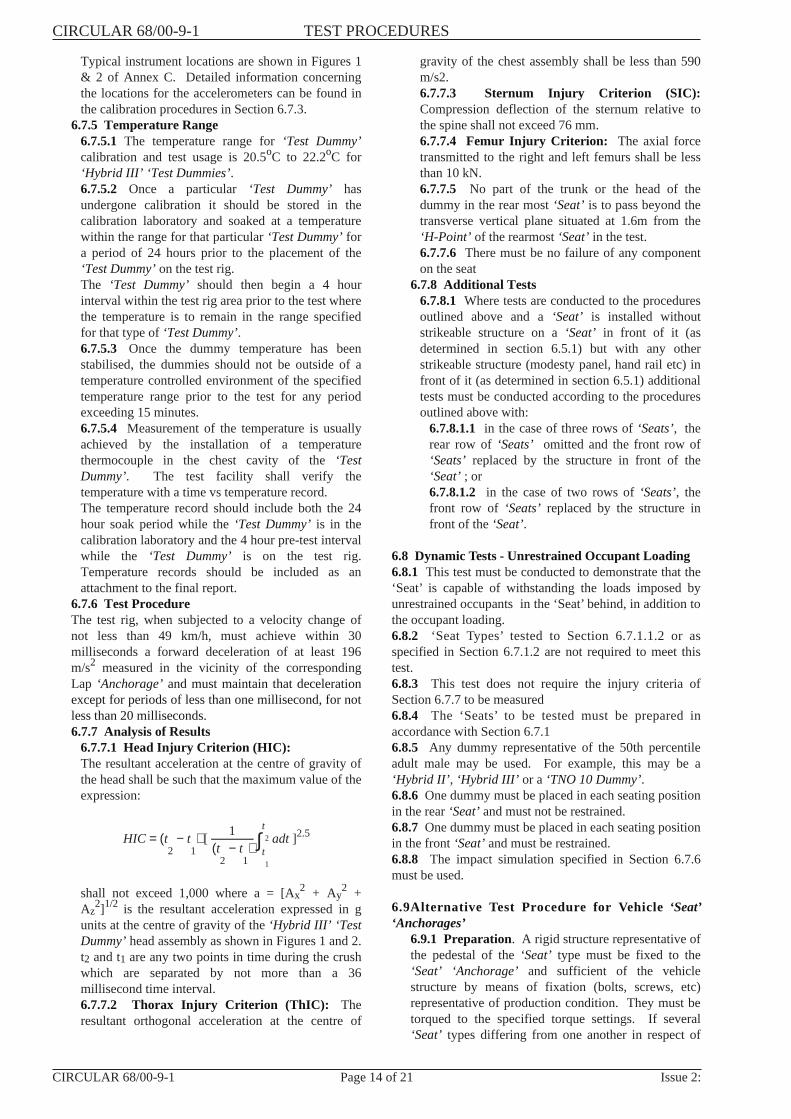
2]1/2 is the resultant acceleration expressed in gunits at the centre of gravity of the‘Hybrid III’ ‘TestDummy’head assembly as shown in Figures 1 and 2.t2 and t1 are any two points in time during the crushwhich are separated by not more than a 36millisecond time interval.6.7.7.2 Thorax Injury Criterion (ThIC): Theresultant orthogonal acceleration at the centre of
gravity of the chest assembly shall be less than 590m/s2.6.7.7.3 Sternum Injury Criterion (SIC):Compression deflection of the sternum relative tothe spine shall not exceed 76 mm.6.7.7.4 Femur Injury Criterion: The axial forcetransmitted to the right and left femurs shall be lessthan 10 kN.6.7.7.5 No part of the trunk or the head of thedummy in the rear most‘Seat’ is to pass beyond thetransverse vertical plane situated at 1.6m from the‘H-Point’ of the rearmost‘Seat’ in the test.6.7.7.6 There must be no failure of any componenton the seat
6.7.8 Additional Tests6.7.8.1 Where tests are conducted to the proceduresoutlined above and a‘Seat’ is installed withoutstrikeable structure on a‘Seat’ in front of it (asdetermined in section 6.5.1) but with any otherstrikeable structure (modesty panel, hand rail etc) infront of it (as determined in section 6.5.1) additionaltests must be conducted according to the proceduresoutlined above with:
6.7.8.1.1 in the case of three rows of‘Seats’, therear row of ‘Seats’ omitted and the front row of‘Seats’ replaced by the structure in front of the‘Seat’ ; or6.7.8.1.2 in the case of two rows of‘Seats’, thefront row of ‘Seats’ replaced by the structure infront of the‘Seat’.
6.8 Dynamic Tests - Unrestrained Occupant Loading6.8.1 This test must be conducted to demonstrate that the‘Seat’ is capable of withstanding the loads imposed byunrestrained occupants in the ‘Seat’ behind, in addition tothe occupant loading.6.8.2 ‘Seat Types’ tested to Section 6.7.1.1.2 or asspecified in Section 6.7.1.2 are not required to meet thistest.6.8.3 This test does not require the injury criteria ofSection 6.7.7 to be measured6.8.4 The ‘Seats’ to be tested must be prepared inaccordance with Section 6.7.16.8.5 Any dummy representative of the 50th percentileadult male may be used. For example, this may be a‘Hybrid II’ , ‘Hybrid III’ or a ‘TNO 10 Dummy’.6.8.6 One dummy must be placed in each seating positionin the rear‘Seat’and must not be restrained.6.8.7 One dummy must be placed in each seating positionin the front‘Seat’and must be restrained.6.8.8 The impact simulation specified in Section 6.7.6must be used.
6.9Alternative Test Procedure for Vehicle ‘Seat’‘Anchorages’
6.9.1 Preparation. A rigid structure representative ofthe pedestal of the‘Seat’ type must be fixed to the‘Seat’ ‘Anchorage’ and sufficient of the vehiclestructure by means of fixation (bolts, screws, etc)representative of production condition. They must betorqued to the specified torque settings. If several‘Seat’ types differing from one another in respect of
CIRCULAR 68/00-9-1 TEST PROCEDURES
CIRCULAR 68/00-9-1 Page 14 of 21 Issue 2:
the distance between the front and back ends of theirfeet can be mounted on the same‘Seat’ ‘Anchorage’,the test must be carried out with the shortest footing.6.9.2 Procedures. Apply a force F at a height of 750mm above the‘Reference Plane’. It must be appliedhorizontally in the front direction of the vehicle on thevertical line containing the geometrical centre of thesurface bounded by the polygon having the extreme‘Seat’ ‘Anchorage’points as apexes and by the rigidstructure representative of the‘Seat’ type pedestal.The force F must be either:- that of a force/time graph which entirelyencompasses the corresponding force/time graphdetermined from a test on the‘Seat’ type according toSection 6.7 (Clause 7) or- the force arising from the tests conducted to Section6.4 (Appendix 1).6.9.3 Analysis of Results - The maximumdisplacement of the point of application of the forcemeasured in the horizontal plane shall not exceed 150mm.
7 REPORTING RESULTS
For each test a complete original test report giving a fulldescription of material tested, dummy calibrations,equipment used, results and order of accuracy is to beprepared. For submissions to the Administrator, thedetermined results for both impact speed and injurycriteria are to be recorded together with the referencenumber of the original test report in the appropriatesection of the Summary of Evidence Report.
All original test data and computations showing methodof determining the results are to be given in the internalreport.
8 SUMMARY OF EVIDENCE REPORTS
The Summary of Evidence Report SE 68/00 is the onlydocument to be sent to the Administrator as evidence fordemonstration of compliance with ADR 68/00. Theoriginal test report reference number, the location of thetest report, the test facility identification number and the
determined results are to be recorded in the appropriateplace in the SE 68/00 form for each relevant Clause of theADR.
9 PROCEDURE FOR DESIGNS CERTIFIED TOALTERNATIVE STANDARDS
Where a copy of an official communication from theAdministrat ive Department ( of the approvinggovernment) giving no less information than that specifiedin United Nations ECE Regulations No. 17(03) or 25(02)in respect of‘Head Restraints’, the technical requirementsof Clause 2 of Appendix 2 of this Rule are deemed to havebeen satisfied.
10 REFERENCES
ADR ReferencesADR DefinitionsADR 68/00 - Occupant Protection in BusesUS Federal Motor Vehicle Regulations Part 572, TestDummies Specifications - Anthropomorphic Test Dummyfor Applicable Test Procedures, Subpart E -‘Hybrid III’‘Test Dummy’- 50th Percentile Male, published by theNational Highway Traffic Safety Administration (400Seventh St. Southwest, Washington DC 20590). Thedrawings referred to in clauses 7 and 8 in Part 572 SubpartE.Part 572 Subclause E referred to in FMVSS 208 issued 4December 1989.ISO 6487 “Technique of measurement in impact tests:Instrumentation” published in 1980.
CircularsCircular 0-12-2 - General Requirements for Test FacilitiesCircular 0-12-3 - General Requirements for Calibration ofTest Equipment and InstrumentationCircular 0-12-6 - Devices for Use in Defining VehicleSeating Accommodation
Other ReferenceISO 4130, 1978 - Three Dimensional Reference System
TEST PROCEDURES CIRCULAR 68/00-9-1
Issue 2: Page 15 of 21 CIRCULAR 68/00-9-1
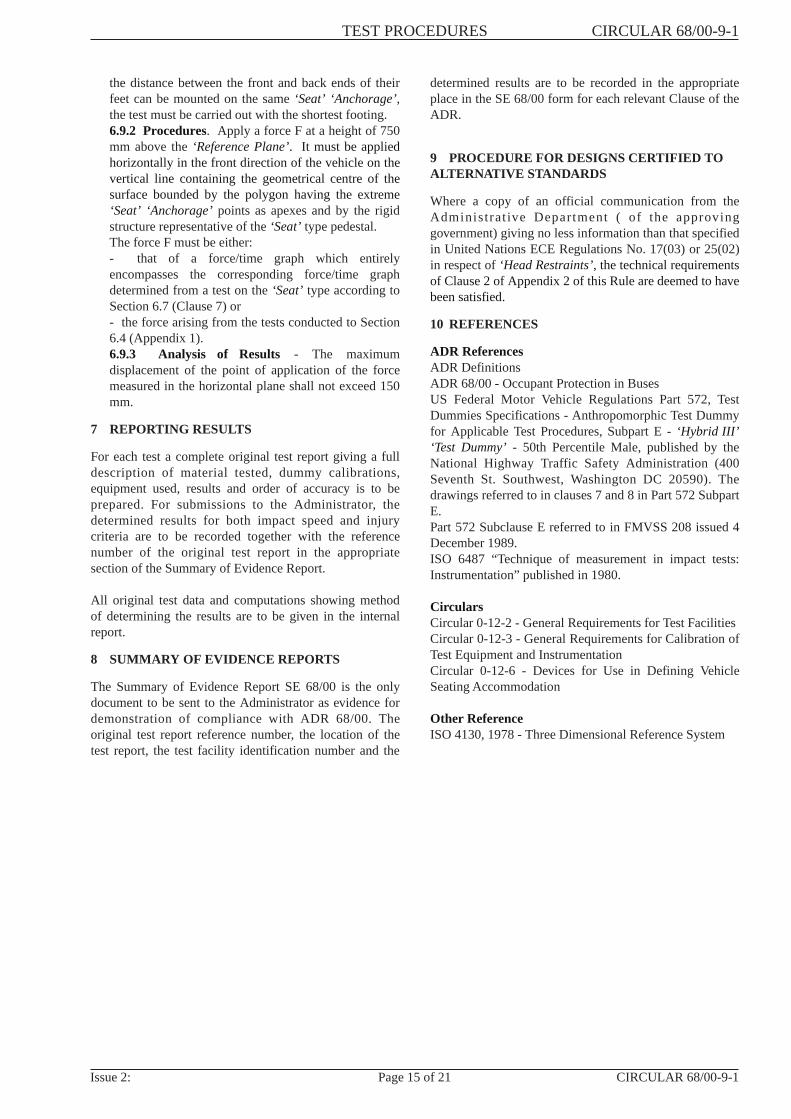
ANNEX A
Test Equipment
Figure 1 Spherical Head Form 165 mm diameter
For application of loads on accessories
Figure 2 70 mm sphere used for detecting sharp edges after completion
of tests using the 165 mm spherical head form
Figure 3 Loading Form for Arm Rest
CIRCULAR 68/00-9-1 TEST PROCEDURES
CIRCULAR 68/00-9-1 Page 16 of 21 Issue 2:

ANNEX A
Figure 4 ‘Seat’ Back Loads - Test Apparatus
TEST PROCEDURES CIRCULAR 68/00-9-1
Issue 2: Page 17 of 21 CIRCULAR 68/00-9-1

ANNEX A
Test Loads
Figure 5 Arm Rest Load Diagram
Application of Loads
Direction Load Location(i) Vertical 1000 N Within 30 mm of each end and at the centre of the arm rest.
Loading form horizontal and transverse across armrest.
(ii) Horizontal 2000 N Applied to the rear upper 30 mm of armrest.Longitudinal Loading form vertical
(iii) Horizontal 1000 N Within 30 mm of ends of armrest.Loading form Vertical
The above forces are to be applied:- in both directions to the forward end of the armrest- towards the seat at the rear end of the armrest- outwards from the seat at the rear end of the armrest if thatpart of the armrest is exposed in any position of the seat.
CIRCULAR 68/00-9-1 TEST PROCEDURES
CIRCULAR 68/00-9-1 Page 18 of 21 Issue 2:
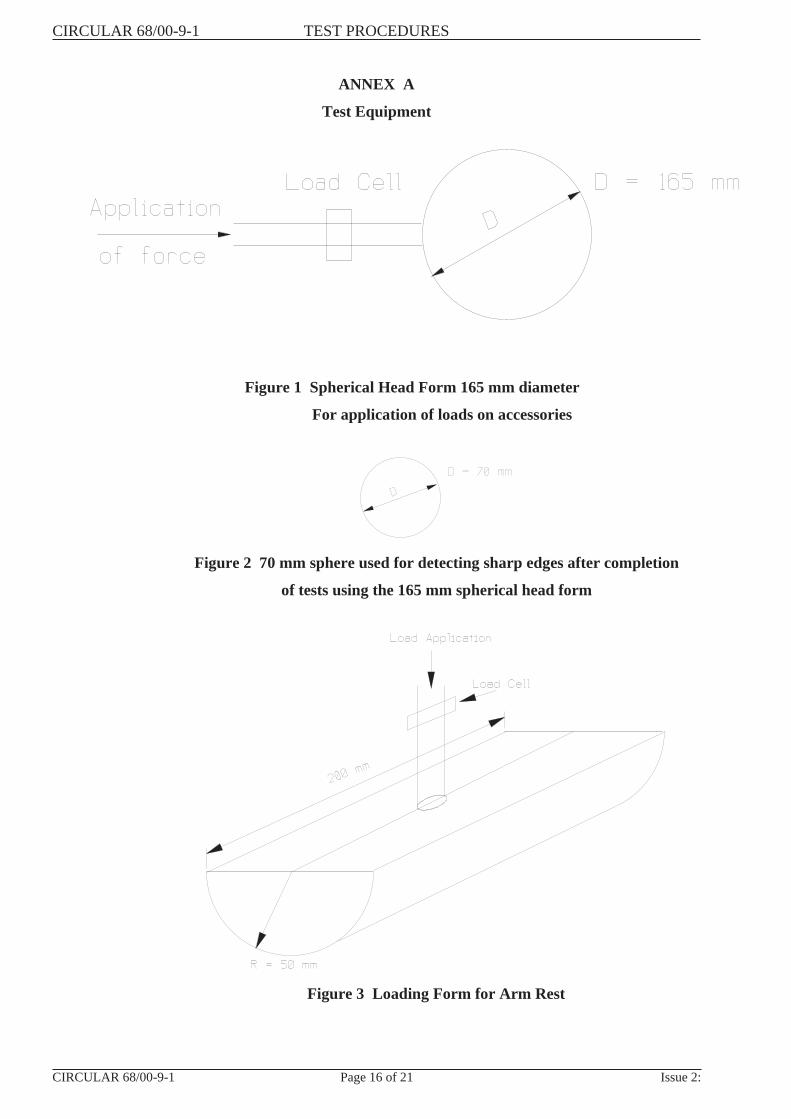
ANNEX B
Typical Body Blocks
Figure 1 Typical Body Blocks
TEST PROCEDURES CIRCULAR 68/00-9-1
Issue 2: Page 19 of 21 CIRCULAR 68/00-9-1
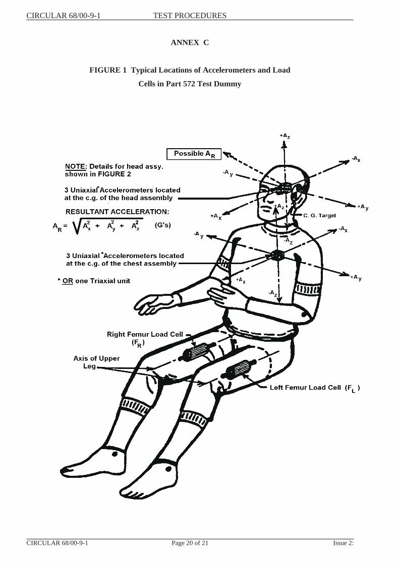
ANNEX C
FIGURE 1 Typical Locations of Accelerometers and Load
Cells in Part 572 Test Dummy
CIRCULAR 68/00-9-1 TEST PROCEDURES
CIRCULAR 68/00-9-1 Page 20 of 21 Issue 2:

ANNEX C
FIGURE 2 Head Injury Criterion
TEST PROCEDURES CIRCULAR 68/00-9-1
Issue 2: Page 21 of 21 CIRCULAR 68/00-9-1