city of los angelesd6449bb3dc657045bfc9-290115cc0d6de62a29c33db202ae565c.r80.cf1… ·...
TRANSCRIPT

BOARD OF BUILDING AND SAFETY
COMMISSIONERS ___
VAN AMBATIELOS
PRESIDENT
E. FELICIA BRANNON VICE-PRESIDENT
JOSELYN GEAGA-ROSENTHAL
GEORGE HOVAGUIMIAN JAVIER NUNEZ
___
CITY OF LOS ANGELES CALIFORNIA
ERIC GARCETTI MAYOR
DEPARTMENT OF BUILDING AND SAFETY 201 NORTH FIGUEROA STREET
LOS ANGELES, CA 90012
____
FRANK BUSH
GENERAL MANAGER SUPERINTENDENT OF BUILDING
OSAMA YOUNAN, P.E.
EXECUTIVE OFFICER ____
RR 25990 Page 1 of 3 LADBS G-5 (REV. 06/30/2014) AN EQUAL EMPLOYMENT OPPORTUNITY - AFFIRMATIVE ACTION EMPLOYER
Foundation Supportworks, Inc. RESEARCH REPORT: RR 25990 12330 Cary Circle (CSI #31 63 00) La Vista, NE 68128 BASED UPON ICC-ES EVALUATION Attn: Jeff Kortan, P.E. REPORT NO. ESR-3074
(402) 861-4744 REEVALUATION DUE Attn: Randy Dikeman DATE: December 1, 2017
(402) 861-4771 Issued Date: March 1, 2017 Code: 2017 LABC GENERAL APPROVAL – Technical Modification - Foundation Supportworks Helical Pier Foundation System for Remedial Repair DETAILS The above assemblies and/or products are approved when in compliance with the use, description, design, installation, conditions of approval, and identification of Evaluation Report No. ESR-3074, reissued July 2015, revised September 2016 of the ICC Evaluation Service, LLC. The report, in its entirety, is attached and made part of this general approval. The parts of Evaluation Report No. ESR-3074 marked by an asterisk are modified or deleted by the Los Angeles City Building Department from this approval. The approval is subject to the following conditions:
1. The Foundation Supportworks Helical Pier Foundation System shall not be used for new buildings or structures.
2. In regard to Condition of Approval 5.2 of the attached ESR-3074, Foundation Supportworks Helical Pier Foundation System is allowed in locations assigned Seismic Design Category D, E, or F, or classified Site Class E or F for remedial repair of existing foundations only.
3. No lateral load capacity is attributed to Foundation Supportworks Helical Pier Foundation System.

Foundation Supportworks RE: Helical Foundation Systems
RR 25990 Page 2 of 3
4. When used for Remedial Repair, lateral stability in accordance with Section 1810.2.2 of the 2017 Los Angeles Building Code is not required.
5. For each project using Foundation Supportworks Helical Pier Foundation System, a geotechnical investigation shall be submitted to the Grading Section for approval addressing the items listed in Section 4.1.1 of the attached ESR -3074.
6. The soil capacity, P4 as shown in Table 1 of the attached ESR-3074, shall be limited to the allowable axial load as a function of the actual installation torque described in Section 4.1.5 of the attached ESR-3074.
7. Plans with complete structural calculations shall be submitted to Structural Plan Check for approval. The structural calculations shall be performed by a Civil or Structural Engineer registered in the State of California and shall be in accordance with the 2017 Los Angeles City Building Code.
8. The existing foundation and bracket shall be attached such that the shaft shall be braced against side-sway. The bracing force shall be at least 0.4 percent of the shaft’s allowable axial capacity in compression.
9. Foundation Supportworks Helical Pier Foundation System shall be fabricated by an Approved Fabricator, licensed by the Los Angeles City Department of Building and Safety.
10. Installation of Foundation Supportworks Helical Pier Foundation System shall comply with manufacturer’s installation procedures, Section 5.0 of the attached ESR-3074, and be conducted under continuous inspection by a Deputy Inspector registered by the Los Angeles Building and Safety Department.
DISCUSSION The technical modification is to recognize model HP350 Helical Foundation System as part of the general approval The report is in compliance with Section 1810.3.1.5 of the 2017 City of Los Angeles Building Code for remedial repair of existing buildings. The approval was based on tests in accordance with ICC ES Acceptance Criteria for Helical Pile Systems and Devices (AC358), dated June 2013 (editorially revised September 2014). This general approval will remain effective provided the Evaluation Report is maintained valid and unrevised with the issuing organization. Any revisions to the report must be submitted to this Department, with appropriate fee, for review in order to continue the approval of the revised report. Addressee to whom this Research Report is issued is responsible for providing copies of it, complete with any attachments indicated, to architects, engineers and builders using items approved herein in design or construction which must be approved by Department of Building and Safety Engineers and Inspectors.

Foundation Supportworks RE: Helical Foundation Systems
RR 25990 Page 3 of 3
This general approval of an equivalent alternate to the Code is only valid where an engineer and/or inspector of this Department has determined that all conditions of this approval have been met in the project in which it is to be used. ______________________________________________ QUAN NGHIEM, Chief Engineering Research Section 201 N. Figueroa St., Room 880 Los Angeles, CA 90012 Phone - 213-202-9812 Fax - 213-202-9943 EB RR25990 TLB1600398 R10/24/2015 1810.3.1.5
Attachment: ICC ES Evaluation Report No.ESR-3074 (12 Pages)
ICC-ES Evaluation Reports are not to be construed as representing aesthetics or any other attributes not specifically addressed, nor are they to be construed as an endorsement of the subject of the report or a recommendation for its use. There is no warranty by ICC Evaluation Service, LLC, express or implied, as to any finding or other matter in this report, or as to any product covered by the report.
Copyright © 2016 International Code Council, LLC. All rights reserved. Page 1 of 12 1000
ICC-ES Evaluation Report ESR-3074 Reissued July 2015
Revised September 2016 This report is subject to renewal July 2017.
www.icc-es.org | (800) 423-6587 | (562) 699-0543 A Subsidiary of the International Code Council ®
DIVISION: 31 00 00—EARTHWORK Section: 31 63 00—Bored Piles REPORT HOLDER: FOUNDATION SUPPORTWORKS, INC. 12330 CARY CIRCLE OMAHA, NEBRASKA 68128 (800) 281-5845 www.foundationsupportworks.com [email protected] EVALUATION SUBJECT: FOUNDATION SUPPORTWORKS HELICAL FOUNDATION SYSTEMS 1.0 EVALUATION SCOPE
Compliance with the following codes: 2015, 2012, 2009 and 2006 International Building
Code® (IBC)
2013 Abu Dhabi International Building Code (ADIBC)† †The ADIBC is based on the 2009 IBC. 2009 IBC code sections referenced in this report are the same sections in the ADIBC. Properties evaluated: Structural
Geotechnical
2.0 USES Foundation Supportworks, Inc. (FSI), Models HP288 and HP350 Helical Foundation Systems are used either to underpin foundations of existing structures or to form deep foundations for new structures, and are designed to transfer axial compression and axial tension loads from the supported structures to suitable soil bearing strata.
3.0 DESCRIPTION 3.1 General: FSI Models HP288 and HP350 helical foundation systems consist of a central lead shaft with one or more helical-shaped steel bearing plates, extension shafts, which may or may not consist of helical bearing plates, shaft couplings that connect multiple shaft sections, and a bracket that allows for attachment to the supported structure. The shafts with helix bearing plates are screwed into the ground by application of torsion and the shaft is extended until a desired depth and/or a suitable soil or bedrock bearing stratum is reached.
3.2 System Components: FSI Models HP288 and HP350 helical foundation systems include a lead shaft (HP288L and HP350LS, respectively), extension shafts (HP288E and HP350E, respectively), Type A side-load brackets (FS288B and FS288BL for Model HP288, and HP350BS for Model HP350), and Type B direct-load brackets (HP288NCB and HP288NCB8 for Model HP288, and HP350NCB and HP350NCB8 for Model HP350), for attachment to concrete foundations. 3.2.1 Helical Lead Sections and Extensions: FSI helical pile lead sections consist of one or more helical-shaped circular steel plates factory-welded to a central steel shaft. The depth of the helical piles in soil is typically extended by adding one or more steel shaft extensions that are mechanically connected together by couplings, to form one, continuous steel pile.
The central steel shaft of the HP288 lead and extension sections is a round, 27/8-inch-outside-diameter (73 mm), 0.276-inch-nominal-wall-thickness (7.0 mm), hollow structural section. The central steel shaft of the HP350 lead and extension sections is a round, 31/2-inch-outside-diameter (88.9 mm), 0.340-inch-nominal-wall-thickness (8.6 mm), hollow structural section. The various shaft lead and extension configurations are listed in Table 5.
Each helical steel bearing plate (helix) is 0.375 inch (9.5 mm) thick, and has a 3-inch (76 mm) pitch and spiral edge geometry with an outer diameter of 8, 10, 12 or 14 inches (203, 254, 305 or 356 mm). The helices are welded to the helical shaft. The lead helix is located about 4 inches from the tip of the shaft lead section. The extensions may consist of the shaft only or include helix plates.
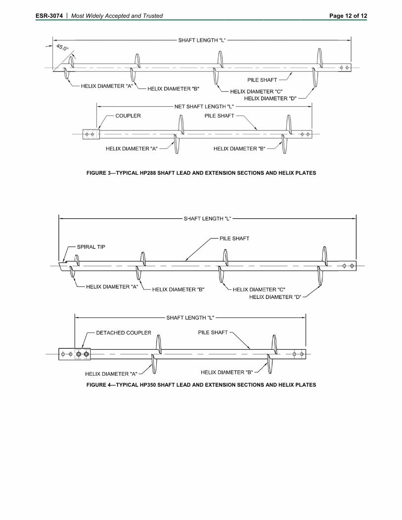
The HP288 extension section couplings consist of a round, 6-inch-long (152.4 mm), 31/2-inch-outside-diameter (89 mm), 0.281-inch-nominal-wall-thickness (7.1 mm), hollow structural section outer sleeve, and two 3/4-inch-diameter (19.1 mm) standard hex threaded bolts and matching standard hex jam nuts. The pipe sleeve is factory-welded to the end of the extension section. (See Figure 3.)
The HP350 extension section couplings consist of a round, 11½-inch-long (152.4 mm), 41/4-inch-outside-diameter (108 mm), 0.344-inch-nominal-wall-thickness (8.7 mm), hollow structural section outer sleeve, and four 1-inch-diameter (25.4 mm) standard hex threaded bolts and matching standard hex jam nuts. The pipe sleeve is slip-fitted over the connected sections. (See Figure 4.)

ESR-3074 | Most Widely Accepted and Trusted Page 2 of 12
3.2.2 Brackets: Brackets are constructed with factory-welded steel plate and steel pipe components. The different brackets are described in Sections 3.2.2.1 through 3.2.2.3. 3.2.2.1 Retrofit Bracket Assemblies FS288B and FS288BL: The FS288B and FS288BL bracket assemblies are designed for use with the HP288 helical shaft and are used to transfer axial compressive loading from existing concrete foundations to the HP288 helical piles. The bracket assembly consists of an FS288B or FS288BL bracket, an external pipe sleeve (FS288ES30 or FS288ES48), a cap plate (FS288C), two threaded rods and matching nuts. (See Figures 1A and 1B.)
The FS288B and FS288BL brackets are constructed from factory-welded, 0.250-inch-, 0.375-inch- and 0.500-inch-thick (6.4 mm, 9.5 mm, and 12.7 mm) steel plates.
The external sleeve (FS288ES30) is manufactured from a 30-inch-long (762 mm), 31/2-inch-outside-diameter (89 mm) and 0.216-inch-nominal-wall-thickness (5.5 mm) pipe with a factory-welded end ring which consists of a 3/4-inch-long (19.1 mm), 4.0-inch-outside-diameter (102 mm) and 0.226-inch-nominal-wall-thickness (6.6 mm) pipe. The FS288ES48 external sleeve is identical to the FS288ES30 except that the FS288ES48 is 48 inches (1219 mm) long.
The FS288C cap plate assembly is manufactured from a 1/2-inch-long (12.7 mm), 31/2-inch-outside-diameter (89 mm), 0.216-inch-nominal-wall-thickness (5.5 mm) steel pipe that is factory-welded to a 1-inch-thick (25.4 mm), 5-inch-wide (127 mm), 9-inch-long (229 mm) steel plate. The cap plate is attached to the retrofit bracket with two 3/4-inch-diameter-by-16-inch-long (19.1 mm by 406 mm) threaded rods, and matching 3/4-inch (19.1 mm) heavy hex nuts. (See Figures 1A and 1B.) 3.2.2.2 Retrofit Bracket Assembly HP350BS: The HP350BS bracket assembly is designed for use with the HP350 helical shaft and is used to transfer axial compressive loading from existing concrete foundations to the HP350 helical piles. The bracket assembly consists of a HP350BS bracket, an external pipe sleeve (FS350ES30), a cap plate (FS350C), two threaded rods and matching nuts. (See Figure 1C.)
The HP350BS brackets are constructed from factory-welded, 0.375-inch- and 0.500-inch-thick (9.5 mm, and 12.7 mm) steel plates.
The external sleeve (FS350ES30) is manufactured from a 30-inch-long (762 mm), 4-inch-outside-diameter (102 mm) and 0.226-inch-nominal-wall-thickness (6.6 mm) pipe with one factory-flared end.
The FS350C cap plate is manufactured from a 23/4-inch (69.9 mm) by 1½-inch (38.1 mm), 0.25-inch-thick (6.4 mm) steel capture plate that is factory-welded to a 1¼-inch-thick (31.8 mm), 8½-inch-wide (216 mm), 4-inch-long (102 mm) steel plate. The cap plate is attached to the retrofit bracket with two 7/8-inch-diameter-by-18-inch-long (22.2 mm by 457 mm) threaded rods, and matching 7/8-inch (22.2 mm) heavy hex nuts. (See Figure 1C.) 3.2.2.3 New Construction Brackets HP288NCB, HP288NCB8, HP350NCB and HP350NCB8: HP288NCB, HP288NCB8, HP350NCB and HP350NCB8 brackets are designed for embedment in cast-in-place concrete foundations. The brackets are used to support axial tensile and compressive loads that are concentric with the longitudinal axis of the shaft. (See Figures 2A and 2B.)
The HP288NCB bracket is manufactured from a 5.06-inch-long (128.5 mm), 31/2-inch-outside-diameter (89 mm), 0.250-inch-nominal-wall-thickness (6.4 mm) steel pipe sleeve which is factory-welded to a 3/4-inch-thick (19.1 mm), 6-inch-square (152 mm) steel cap plate. The bracket is attached to the shaft with two 3/4-inch-diameter (19.1 mm) standard hex threaded bolts and with matching 3/4-inch (19.1 mm) standard hex jam nuts. (See Figure 2A.)
The HP288NCB8 bracket is identical to the HP288NCB bracket except that the HP288NCB8 cap plate is an 8-inch-square (203 mm) steel plate. (See Figure 2A.)
The HP350NCB bracket is manufactured from a 6.28-inch-long (160 mm), 41/4-inch-outside-diameter (108 mm), 0.313-inch-nominal-wall-thickness (8.0 mm) steel pipe sleeve which is factory-welded to a 3/4-inch-thick (19.1 mm), 7-inch-square (178 mm) steel cap plate. The bracket is attached to the shaft with two 1-inch-diameter (25.4 mm) standard hex threaded bolts and with matching 1-inch (25.4 mm) standard hex jam nuts. (See Figure 2B.)
The HP350NCB8 bracket is identical to the HP350NCB bracket except that the HP350NCB8 cap plate is an 8-inch-square (203 mm) steel plate. (See Figure 2B.)
3.3 Material Specifications:
3.3.1 HP288 Lead and Extension Shafts: The HP288 leads and extensions are carbon steel round structural tubes that conform to ASTM A500, Grade B or C, having a minimum yield strength of 60 ksi (413 MPa) and a minimum tensile strength of 70 ksi (483 MPa). The shaft finish is either plain steel or hot-dip galvanized in accordance with ASTM A123.
3.3.2 HP350 Lead and Extension Shafts: The HP350 leads and extensions are carbon steel round structural tubes that conform to ASTM A500, Grade B or C, having a minimum yield strength of 65 ksi (448 MPa) and a minimum tensile strength of 75 ksi (517 MPa). The shaft finish is either plain steel or hot-dip galvanized in accordance with ASTM A123.
3.3.3 Shaft Coupling:
3.3.3.1 Pipe Sleeves (For HP288 and HP350 Shafts): The sleeves are carbon steel round structural tubing that conforms to ASTM A513, Type 5, Drawn Over a Mandrel (DOM), Grade 1026, having a minimum yield strength of 70 ksi (483 MPa) and a minimum tensile strength of 80 ksi (552 MPa). The sleeve finish is either plain steel or hot-dip galvanized in accordance with ASTM A123.
3.3.3.2 HP288 Bolts and Nuts: The steel coupling bolts are 3/4–10 UNC 2A standard hex bolts conforming to SAE J429, Grade 8, having a minimum yield strength of 130 ksi (896 MPa) and a minimum tensile strength of 150 ksi (1034 MPa). The matching steel nuts are 3/4–10 UNC 2B standard hex jam nuts, conforming to SAE J995, Grade 5. The bolts and nuts are zinc-coated in accordance with ASTM B633, with coating classification Fe/Zn 8.
3.3.3.3 HP350 Bolts and Nuts: The steel coupling bolts are 1–8 UNC 2A standard hex bolts conforming to SAE J429, Grade 5, having a minimum yield strength of 92 ksi (634 MPa) and a minimum tensile strength of 120 ksi (827 MPa). The matching steel nuts are 1–8 UNC 2B standard hex jam nuts, conforming to SAE J995, Grade 5. The bolts and nuts are zinc-coated in accordance with ASTM B633, with coating classification Fe/Zn 8.

ESR-3074 | Most Widely Accepted and Trusted Page 3 of 12
3.3.4 Helix Plates (For HP288 and HP350 Shafts): The steel plates conform to ASTM A572, Grade 50, having a minimum yield strength of 50 ksi (345 MPa) and a minimum tensile strength of 65 ksi (448 MPa). The helix finish is the same as that of the shaft to which the helix is factory-welded. 3.3.5 Retrofit Bracket Assemblies FS288B and FS288BL: 3.3.5.1 FS288B and FS288BL Brackets: The steel plates used in the brackets conform to ASTM A36, having a minimum yield strength of 36 ksi (248 MPa) and a minimum tensile strength of 58 ksi (400 MPa). The bracket finish is either plain steel or hot-dip galvanized in accordance with ASTM A123. 3.3.5.2 FS288ES30 and FS288ES48 Sleeves: The carbon steel structural round tubing, used for the 30-inch- and 48-inch-long (762 mm and 1219 mm) sleeves, conforms to ASTM A500, Grade B or C, having a minimum yield strength of 50 ksi (345 MPa) and a minimum tensile strength of 62 ksi (427 MPa). The 3/4-inch-long (19.1 mm) steel ring (collar) conforms to ASTM A53, Types E and S, Grade B, having a minimum yield strength of 35 ksi (241 MPa) and a minimum tensile strength of 60 ksi (413 MPa). The sleeve finish is either plain steel or hot-dip galvanized in accordance with ASTM A123. 3.3.5.3 FS288C Cap Plate Assembly: The 1/2-inch-long (12.7 mm) steel pipe conforms to ASTM A53, Types E and S, Grade B, having a minimum yield strength of 35 ksi (241 MPa) and a minimum tensile strength of 60 ksi (413 MPa). The steel cap plate conforms to ASTM A572, Grade 50, having a minimum yield strength of 50 ksi (345 MPa) and a minimum tensile strength of 65 ksi (448 MPa). The cap plate assembly finish is either plain steel or hot-dip galvanized in accordance with ASTM A123. 3.3.5.4 Threaded Rods and Nuts: The 3/4-inch-diameter steel threaded rods conform to ASTM A193, Grade B7, having a minimum yield strength of 105 ksi (724 MPa) and a minimum tensile strength of 125 ksi (862 MPa). The matching 3/4-inch-diameter steel heavy hex nuts conform to ASTM A563 Grade DH or DH3, or ASTM A194 Grade 2H. The threaded rods and nuts are zinc-coated in accordance with ASTM B633, with coating classification Fe/Zn 8.
3.3.6 Retrofit Bracket Assembly HP350BS: 3.3.6.1 HP350BS Bracket: The steel plates used in the bracket conform to ASTM A36, having a minimum yield strength of 36 ksi (248 MPa) and a minimum tensile strength of 58 ksi (400 MPa). The bracket finish is either plain steel or hot-dip galvanized in accordance with ASTM A123. 3.3.6.2 FS350ES30 Sleeve: The carbon steel structural round tubing, used for the 30-inch-long (762 mm) sleeve, conforms to ASTM A500, Grade B or C, having a minimum yield strength of 50 ksi (345 MPa) and a minimum tensile strength of 62 ksi (427 MPa). The sleeve finish is either plain steel or hot-dip galvanized in accordance with ASTM A123. 3.3.6.3 FS350C Cap Plate: The 1¼-inch-thick (31.8 mm) steel plate conforms to ASTM A572, Grade 50, having a minimum yield strength of 50 ksi (345 MPa) and a minimum tensile strength of 65 ksi (448 MPa). The 0.25-inch-thick steel capture plate conforms to ASTM A36, having a minimum yield strength of 36 ksi (248 MPa) and a minimum tensile strength of 58 ksi (400 MPa). The
cap plate finish is either plain steel or hot-dip galvanized in accordance with ASTM A123. 3.3.6.4 Threaded Rods and Nuts: The 7/8-inch-diameter steel threaded rods conform to ASTM A193, Grade B7, having a minimum yield strength of 105 ksi (724 MPa) and a minimum tensile strength of 125 ksi (862 MPa). The matching 7/8-inch-diameter steel heavy hex nuts conform to ASTM A563 Grade DH or DH3, or ASTM A194 Grade 2H. The threaded rods and nuts are zinc-coated in accordance with ASTM B633, with coating classification Fe/Zn 8. 3.3.7 New Construction Brackets HP288NCB, HP288NCB8, HP350NCB and HP350NCB8: 3.3.7.1 Plates: The steel plates conform to ASTM A36, having a minimum yield strength of 36 ksi (248 MPa) and a minimum tensile strength of 58 ksi (400 MPa). The plate finish is either plain steel or hot-dip galvanized in accordance with ASTM A123. 3.3.7.2 Pipe Sleeves: The pipe sleeves are steel round structural tubes that conform to ASTM A513, Type 5, Drawn Over a Mandrel (DOM), Grade 1026, having a minimum yield strength of 70 ksi (483 MPa) and a minimum tensile strength of 80 ksi (552 MPa). The sleeve finish is either plain steel or hot-dip galvanized in accordance with ASTM A123. 3.3.7.3 Bolts and Nuts: The steel bolts and nuts are those described in Section 3.3.3.2 for the HP288 shaft and Section 3.3.3.3 for the HP350 shaft.
4.0 DESIGN AND INSTALLATION 4.1 Design: 4.1.1 General: Structural calculations (analysis and design) and drawings, prepared by a registered design professional, must be approved by the code official for each project, and must be based on accepted engineering principles as described in IBC Section 1604.4, and must conform to Section 1810 of the 2015, 2012 and 2009 IBC (Section 1808 of the 2006 IBC). The design method for the steel components is Allowable Strength Design (ASD), described in IBC Section 1602 and AISC 360 Section B3.4. The structural analysis must consider all applicable internal forces due to applied loads, structural eccentricity, and maximum spans between helical foundations. The result of this analysis, and the structural capacities, shall be used to select a helical foundation system.
The ASD capacities of FSI helical foundation system components are indicated in Tables 1, 2, 3, and 5. The geotechnical analysis must address the suitability of the helical foundation system for the specific project. It must also address the center-to-center spacing of the helical piles, considering both effects on the supported foundation and structure and group effects on the pile-soil capacity. The analysis must include estimates of the axial tension and/or compression capacities of the helical piles, whatever is relevant for the project, and the expected total and differential foundation movements due to single pile or pile group, as applicable.
A written report of the geotechnical investigation must be submitted to the code official as one of the required submittal documents, prescribed in Section 107 of the 2015, 2012 and 2009 IBC (Section 106 of the 2006 IBC), at the time of the permit application. The geotechnical report must include, but need not be limited to, the following information:
1. A plot showing the location of the soil investigation.

ESR-3074 | Most Widely Accepted and Trusted Page 4 of 12
2. A complete record of the soil boring and penetration test logs and soil samples.
3. A record of soil profile.
4. Information on groundwater table, frost depth and corrosion-related parameters, as described in Section 5.5 of this report.
5. Soil properties, including those affecting the design such as support conditions for the piles.
6. Recommendations for design criteria, including but not limited to mitigations of effects of differential settlement and varying soil strength, and effects of adjacent loads.
7. Field inspection and reporting procedures (to include procedures for verification of the installed bearing capacity when required).
8. Load test requirements.
9. Any questionable soil characteristics and special design provisions, as necessary.
4.1.2 Bracket Capacity (P1): Only the localized limit state of concrete bearing strength in compression has been evaluated for this evaluation report. All other limit states related to the concrete foundation, such as those limit states described in Chapter 17 of ACI 318-14 under the 2015 IBC (ACI 318 Appendix D under the 2012, 2009 and 2006 IBC), punching (two-way) shear, beam (one-way) shear, and flexural (bending) related limit states, have not been evaluated for this evaluation report. The concrete foundation must be designed and justified to the satisfaction of the code official with due consideration to all applicable limit states, and the direction and eccentricity of applied loads, including reactions provided by the brackets acting on the concrete foundation. (See Tables 1, 2 and 3.) 4.1.3 Shaft Capacity (P2): The tops of shafts must be braced as prescribed in Section 1810.2.2 of the 2015, 2012 and 2009 IBC (Section 1808.2.5 of the 2006 IBC). In accordance with Section 1810.2.1 of the 2015, 2012 and 2009 IBC (Section 1808.2.9 of the 2006 IBC), any soil other than fluid soil is deemed to afford sufficient lateral support to prevent buckling of systems that are braced. When piles are standing in air, water or fluid soils, the unbraced length is defined as the length of pile that is standing in air, water or fluid soils plus an additional 5 feet (1524 mm) when embedded into firm soil, or an additional 10 feet (3048 mm) when embedded into soft soil. Firm soils are defined as any soil with a Standard Penetration Test (SPT) blow count of five or greater. Soft soil is defined as any soil with an SPT blow count greater than zero and less than five. Fluid soil is defined as any soil with an SPT blow count of zero [weight of hammer (WOH) or weight of rods (WOR)]. The SPT blow counts must be determined in accordance with ASTM D1586. For fully braced conditions where the pile is installed in accordance with Section 1810.2.2 of the 2015, 2012 and 2009 IBC (Section 1808.2.5 of the 2006 IBC) and piles do not stand in air, water, or fluid soils, the allowable shaft capacities must not exceed the maximum design loads shown in Tables 1, 2 and 5. Shaft capacities of helical foundation systems in air, water or fluid soils must be determined by a registered design professional. The ASD shaft tension capacities are shown in Tables 3 and 5, the ASD shaft compression capacities are shown in Tables 1, 2 and 5, and the shaft torsional rating is shown in Table 5.
The elastic shortening/lengthening of the pile shaft will be controlled by the applied loads and the mechanical and geometrical properties of the HP288 or HP350 shafts
and the shaft couplings. The shaft elastic shortening or lengthening can be determined from the equation:
∆shaft = P × LA × E
(Eq. 1)
where:
∆shaft = change in shaft length due to elastic shortening or lengthening (inches)
P = applied axial compression or tension load (lbf)
L = pile shaft length (inches)
A = shaft cross-sectional area (in2) (see Table 4)
E = shaft steel modulus of elasticity (psi) (see Table 4)
4.1.4 Helix Plate Capacity (P3): The allowable axial compression and tension load capacities (P3) for each individual helical plate diameter (8, 10, 12 or 14 inches) is 40 kips (177.9 kN). (See Tables 1, 2, 3 and 5.) For helical piles with more than one helix, the allowable helix capacity (P3) for the helical foundation system may be taken as the sum of the allowable capacity of each individual helix. 4.1.5 Soil Capacity (P4): The allowable axial compressive or tensile soil capacity (P4) can be estimated by a registered design professional in accordance with a site-specific geotechnical report, as described in Section 4.1.1, combined with the individual helix bearing method (Method 1), or from field loading tests conducted under the supervision of a registered design professional (Method 2). For either Method 1 or Method 2, the predicted axial load capacities must be confirmed during the site-specific production installation, such that the axial load capacities predicted by the torque correlation method are equal to or greater than those predicted by Method 1 or 2, described above.
With the individual helix bearing method, the total nominal axial load capacity of the helical pile is determined as the sum of the individual areas of the helical bearing plates times the ultimate bearing capacities of the soil or rock comprising the respective bearing strata for the plates.
The design allowable axial load must be determined by dividing the total ultimate axial load capacity predicted by either Method 1 or 2, above, by a factor of safety (FOS) of at least 2.0.
With the torque correlation method, the total ultimate and allowable axial load capacities are predicted as follows: Qult = Kt T (Eq. 2)
Qall = Qult/FOS (Eq. 3)
FOS 2.0
Where:
Qult = Ultimate axial tensile or compressive capacity (lbf or N) of the helical piles.
Qall = Allowable axial tensile or compressive capacity (P4) (lbf or N) of the helical piles. See Tables 1, 2, 3 and 5 for the allowable soil capacity of the HP288 and HP350 systems, based on the torque correlation method.
Kt = Torque correlation factor. (See Table 5.)
T = Final installation torque, which is the final torque recorded at the termination (final) depth of the installed pile during the field installations (lbf-ft or N-m).

ESR-3074 | Most Widely Accepted and Trusted Page 5 of 12
4.1.6 Foundation System: The ASD allowable capacity of the FSI helical foundation system in tension and compression depends upon the analysis of interaction of brackets, shafts, helical plates and soils; must be the lowest value of P1, P2, P3 and P4; and must be no larger than 60 kips (266.9 kN). 4.1.6.1 Foundation System (2015, 2012 and 2009 IBC): Under the 2015, 2012 and 2009 IBC, the additional requirements described in this section (Section 4.1.6.1) must be satisfied. For all design methods permitted under Section 4.1.1 of this report, the allowable axial compressive and tensile load of the helical pile system must be based on the least of the following conditions in accordance with 2015, 2012 and 2009 IBC Section 1810.3.3.1.9:
x P4: Allowable load predicted by the individual helix bearing method (or Method 1) described in Section 4.1.5 of this report.
x P4: Allowable load predicted by the torque correlation method described in Section 4.1.5 of this report.
x P4: Allowable load predicted by dividing the ultimate capacity determined from load tests (Method 2 described in Section 4.1.5) by a factor of safety of at least 2.0. This allowable load will be determined by a registered design professional for each site-specific condition.
x P2: Allowable capacities of the shaft and shaft couplings. See Section 4.1.3 of this report.
x P3: Sum of the allowable axial capacity of helical bearing plates affixed to the pile shaft. See Section 4.1.4 of this report.
x P1: Allowable axial load capacity of the bracket. See Section 4.1.2 of this report.
4.2 Installation: 4.2.1 General: The FSI helical foundation systems must be installed by FSI trained and certified installers. The FSI helical foundation systems must be installed in accordance with Section 4.2, 2015, 2012 and 2009 IBC Section 1810.4.11, site-specific approved construction documents (engineering drawings and specifications), and the manufacturer’s written installation instructions. In case of conflict, the most stringent requirement governs. 4.2.2 Helical Pile Installation: The helical piles are typically installed using hydraulic rotary motors having forward and reverse capabilities. The foundation piles must be aligned both vertically and horizontally as specified in the approved plans. The helical piles must be installed in a continuous manner with the pile advancing at a rate equal to at least 85 percent of the helix pitch per revolution at the time of final torque measurement. Installation speeds must be limited to less than 25 revolutions per minute (rpm). The lead and extension sections must be attached to the drive head with a product adaptor supplied by FSI. Torque readings must be taken at minimum intervals corresponding to each lead or extension section length and at final termination depth. The lead and extension sections are connected with the coupling bolts and nuts described in Section 3.2.1, and tightened to a snug-tight condition as defined in Section J3 of AISC 360. The final installation torque must equal or exceed that as specified by the torque correlation method (see Section 4.1.5), in order to support the allowable design loads of the structure using a torque correlation factor (Kt) of 9 ft-1 (29.5 m-1) for the HP288 shaft and a Kt of 7 ft-1 (23.0 m-1) for the HP350 shaft. The installation
torque must not exceed 7,898 ft-lbs (10 708 N-m) for the HP288 shaft and must not exceed 17,500 ft-lbs (23,727 N-m) for the HP350 shaft. See Section 5.0 for further installation conditions of use. 4.2.3 Retrofit Bracket Installation: 1. An area must be excavated to expose the footing with
an excavation approximately 3 feet (914 mm) square and with a depth of about 13 inches (330 mm) below the bottom of the footing. The soil is removed below the bottom of the footing to about 9 inches (229 mm) from the footing face in the area where the bracket bearing plate will be placed. The vertical and bottom faces of the footing must, to the extent possible, be smooth and at right angles to each other for the mounting of the support bracket.
2. Notching of footings may be needed to place the retrofit bracket directly under the wall/column. Notching must be performed, however, only with the acceptance of the registered design professional and the approval of the code official.
3. The bearing surfaces of the concrete (bottom and side of footing) must be prepared so that they are smooth and free of all soil, debris and loose concrete so as to provide a full and firm contact of the retrofit bracket plates.
4. The edge of the lead section shaft must be located about 11/2 inches (38 mm) from the bottom edge of the footing with a required angle of inclination of 3.0 ± 1.0 degrees from the vertical for the HP288 shaft and 3.2 ± 1.0 degrees from the vertical for the HP350 shaft. Installation must be as described in Section 4.2.2.
5. When the final bearing depth is reached, the pile shafts are cut to approximately 13 inches (330 mm) above the bottom of footing.
6. The external sleeve must be placed through the bracket body and over the shaft. Once under the footing, the bracket must be rotated 180 degrees toward the footing. The bracket must be raised up to the footing and held in place while the thread rods and cap plate are attached.
7. The cap plate and all thread rods and tightening nuts must be installed to snug the bracket to the bottom of the footing.
8. Soil must be placed and compacted adequately up to the bottom of the bracket prior to structural lift or load transfer.
9. A lift cylinder can be used to lift the structure to desired elevation and to transfer the designated portion of the foundation load to the helical pile system.
10. Lifting of the existing foundation structure must be verified by the registered design professional and is subject to approval of the code official to ensure that the foundation and superstructure are not overstressed.
11. Field installation logs must be completed and excavation pits or trenches must be backfilled and compacted. Proper compaction procedures must comply with the approved construction documents for any site-specific requirement. When possible or as required by the approved construction document, grades or other means must be constructed to allow proper, positive surface drainage away from the structure.

ESR-3074 | Most Widely Accepted and Trusted Page 6 of 12
4.2.4 New Construction Bracket Installation:
1. The helical pile must be installed in accordance with Section 4.2.2 with an allowable angular tolerance of ± 1 degree from the vertical.
2. The top of pile elevation must be established and must be consistent with the specified elevation. If necessary, the pile can be cut off in accordance with the manufacturer’s instructions at the required elevation.
3. The new construction bracket must be placed over the top of the pile, with the bracket cap plate in full, direct contact (bearing) with the top of the pile shaft.
4. If the pile is used to resist tension forces, the new construction bracket must be embedded with proper distance into the footing or grade beam as required to resist the tension loads as determined by a registered design professional. For piles used to resist tension or compression loads, each new construction bracket must be through-bolted to the helical pile shaft with two bolts and matching nuts as specified in Sections 3.2.2.3 and 3.3.7.3, and installed to a snug-tight condition in accordance with Section 4.2.2. Refer to Tables 2 and 3 for the proper embedded edge distance requirements for the shaft and bracket.
4.3 Special Inspection:
Continuous special inspection in accordance with Section 1705.9 of the 2015 and 2012 IBC (Section 1704.10 of the 2009 IBC, and Section 1704.9 of the 2006 IBC) must be provided for the installation of foundation piles and foundation brackets. Where on-site welding is required, special inspection in accordance with Section 1705.2 of the 2015 and 2012 IBC (Section 1704.3 of the 2009 and 2006 IBC) is also required. Items to be confirmed by the special inspector include, but are not limited to, the manufacturer’s certification of installers, verification of the product manufacturer, helical pile and bracket configuration and identification, inclination and position of the helical pies, the installation torque and depth of the foundation piles, compliance of the installation with the approved construction documents and this evaluation report.
5.0 CONDITIONS OF USE
Foundation Supportworks, Inc. (FSI), Models HP288 and HP350 Helical Foundation Systems described in this report comply with the 2015, 2012 and 2009 IBC, and are suitable alternatives to what is specified in the 2006 IBC, subject to the following conditions:
5.1 The FSI helical foundation systems are manufactured, identified and installed in accordance with this report, approved construction documents (engineering drawings and specifications), and the manufacturer’s written installation instructions. In case of conflict, the most stringent requirement governs.
5.2 The FSI helical foundation systems have been evaluated for support of structures assigned to Seismic Design Categories A, B and C in accordance with IBC Section 1613. Helical foundation systems that support structures assigned to Seismic Design Category D, E or F, or that are located in Site Class E or F, are outside the scope of this report, and are subject to the approval of the code official, based upon submission of an engineering design in accordance with the code by a registered design professional.
5.3 Installations of the helical foundation systems are limited to regions of concrete members where analysis indicates no cracking occurs at service load levels.
5.4 Retrofit and new construction brackets must be used only to support structures that are laterally braced as defined in Section 1810.2.2 of the 2015, 2012 and 2009 IBC (Section 1808.2.5 of the 2006 IBC).
5.5 Use of FSI helical foundation systems in exposure conditions to soil that are indicative of potential pile deterioration or corrosion situations as defined by the following: (1) soil resistivity of less than 1,000 ohm-cm; (2) soil pH of less than 5.5; (3) soils with high organic content; (4) soil sulfate concentrations greater than 1,000 ppm; (5) soils located in a landfill; or (6) soil containing mine waste, is beyond the scope of this evaluation report.
5.6 Zinc-coated steel and bare steel components must not be combined in the same system, except where the sacrificial thickness (Ts) for the zinc-coated components is taken as that given for bare steel components (0.036 inch or 915 μm). All helical foundation components must be galvanically isolated from concrete reinforcing steel, building structural steel, or any other metal building components.
5.7 The new construction helical piles (piles with new construction brackets) must be installed vertically plumb into the ground with a maximum allowable angle of inclination tolerance of 0° ± 1°. To comply with requirements found in Section 1810.3.1.3 of the 2015, 2012 and 2009 IBC (Section 1808.2.8 of the 2006 IBC), the superstructure must be designed to resist the effects of helical pile mislocation.
5.8 The retrofit helical piles must be installed at a maximum angle of inclination of 3.0 ± 1.0 degrees from the vertical for the HP288 shaft and 3.2 ± 1.0 degrees from the vertical for the HP350 shaft.
5.9 Special inspection is provided in accordance with Section 4.3 of this report.
5.10 Engineering calculations and drawings, in accordance with recognized engineering principles as described in IBC Section 1604.4, and complying with Section 4.1 of this report and prepared by a registered design professional, are provided to, and approved by, the code official.
5.11 The adequacy of the concrete structures that are connected to the FSI brackets must be verified by a registered design professional, in accordance with applicable code provisions, such as Chapter 13 of ACI 318-14 under the 2015 IBC (Chapter 15 of ACI 318-11, -08 and -05 under the 2012, 2009 and 2006 IBC respectively) and Chapter 18 of the IBC. The adequacy is subject to the approval of the code official.
5.12 A geotechnical investigation report for each project site must be provided to the code official for approval in accordance with Section 4.1.1 of this report.
5.13 When using the alternative basic load combinations prescribed in IBC Section 1605.3.2, the allowable stress increases permitted by material chapters of the IBC (including Chapter 18) or the referenced standards are prohibited.
5.14 The minimum helical pile center-to-center spacing must be three times the largest helical bearing plate diameters at the depth of bearing. For piles with

ESR-3074 | Most Widely Accepted and Trusted Page 7 of 12
closer spacing, the pile allowable load reductions due to pile group effects must be included in the geotechnical report described in Section 4.1.1 of this report, and must be considered in the pile design by a registered design professional. The spacing and load reductions, if applicable, are subject to the approval of the code official.
5.15 For piles supporting tension loads, the piles must be installed such that the minimum depth from the ground surface to the uppermost helix is 12D, where D is the diameter of the largest helix. In cases where the installation depth is less than 12D, the minimum embedment depth must be determined by a registered design professional based on site-specific soil conditions, and the determination is subject to the approval of the code official. For tension applications where the helical pile is installed at an embedment depth of less than 12D, the torque-correlation soil capacity, P4, is outside of the scope of this evaluation report.
5.16 Evaluation of compliance with Section 1810.3.11.1 of the 2015, 2012 and 2009 IBC (Section 1808.2.23.1.1 of the 2006 IBC) for buildings assigned to Seismic Design Category (SDC) C, and with Section 1810.3.6 of the 2015, 2012 and 2009 IBC (Section 1808.2.7 of the 2006 IBC) for all buildings, is outside the scope of this evaluation report. Such compliance must be addressed by a registered design professional for each site, and the work of the design professional is subject to approval of the code official.
5.17 Requirements listed in the footnotes to Tables 1, 2, 3, and 5 must be satisfied.
5.18 Settlement of helical piles is beyond the scope of this evaluation report, and must be determined by a registered design professional as required in Section 1810.2.3 of the 2015, 2012 and 2009 IBC (Section 1808.2.12 of the 2006 IBC).
5.19 The FSI helical foundation systems are manufactured at the following facilities: Distefano Technology & Manufacturing Company, 3838 South 108th Street, Omaha, Nebraska; Behlen Manufacturing Company, 4025 East 23rd Street, Columbus, Nebraska; and TSA Manufacturing, 14901 Chandler Road, Omaha, Nebraska. Manufacturing is done under a quality-control program with inspections by ICC-ES.
6.0 EVIDENCE SUBMITTED Data in accordance with the ICC-ES Acceptance Criteria for Helical Pile Systems and Devices (AC358), dated June 2013 (editorially revised September 2014).
7.0 IDENTIFICATION The FSI helical foundation system components described in this report are identified by labels that include the report holder’s name (Foundation Supportworks, Inc.); the name and address of Distefano Technology & Manufacturing Company, Behlen Manufacturing Company, or TSA Manufacturing; the product name; the model number (HP288 or HP350); the part number; and the evaluation report number (ESR-3074).
TABLE 1—HP288 AND HP350 (WITH RETROFIT BRACKETS) ASD COMPRESSION CAPACITIES
Bracket Part No.1 Sleeve Part No.1 Bracket Description
Allowable Compression Capacity (kips)
Bracket (P1)2
Shaft (P2)3
Helix (P3)4
(Per Helix Plate)
Minimum Number of Helix Plates5
Soil (P4)6
Foundation System7
FS288B FS288ES30 HP288 Standard Bracket w/30" Sleeve
24.9 60.0 40.0 1 35.5 24.9 FS288B-G FS288ES30-G 27.9 60.0 40.0 1 35.5 27.9 FS288B FS288ES48 HP288 Standard Bracket w/48"
Sleeve 31.4 60.0 40.0 1 35.5 31.4
FS288B-G FS288ES48-G 35.1 60.0 40.0 1 35.5 35.1 FS288BL FS288ES30 HP288 Low Profile Bracket
w/30" Sleeve 25.3 60.0 40.0 1 35.5 25.3
FS288BL-G FS288ES30-G 28.2 60.0 40.0 1 35.5 28.2 HP350BS FS350ES30 HP350 Standard Bracket w/30”
Sleeve 45.4 60.0 40.0 2 60.0 45.4
HP350BS-G FS350ES30-G 49.2 60.0 40.0 2 60.0 49.2 For SI: I inch = 25.4 mm, 1 kip = 1000 lbf = 4.448 kN. 1Part numbers with “G” suffix indicate hot-dip galvanized coating. Part numbers without a “G” suffix indicate plain steel. 2Bracket capacity is based on full scale load tests per AC358 with an installed 5'-0" unbraced pile length per Section 1810.2.1 of the 2015, 2012 and 2009 IBC (Section 1808.2.9.2 of the 2006 IBC), having a maximum of one coupling. 3Shaft capacity is applicable only to the foundation systems that are fully braced as described in Section 4.1.3. 4Helix capacity is based on a single helix plate with outer diameter of 8, 10, 12 or 14 inches (203, 254, 305 or 356 mm). 5The minimum number of helix plates that must be used to achieve the full foundation system capacity. 6Soil capacity is based on torque correlation per Section 4.1.5 of this report, with piles installed at the maximum torsion rating. 7Foundation system allowable capacity is based on the lowest of P1, P2, P3 and P4 listed in this table. See Section 4.1.6 for additional requirements.

E
F1
2
s3
4
5
6
7
8
3t
ESR-3074 | M
TAB
Bracket Part No.1
HP288NCB or HP288NCB-G
HP288NCB8 HP288NCB8-G
HP350NCB or HP350NCB-G
HP350NCB8 or HP350NCB8-G
For SI: I inch = 251Part numbers wit2Bracket capacity shear, have not be3Shaft capacity is 4Helix capacity is 5The minimum nu6Soil capacity is b7Foundation syste8Reduction of plai318-14 for the 201the 2006 IBC) is a
Most Widely Acc
FIGURES 1A
BLE 2—HP288 A
Bearing Plate Dimensions (in)
6 x 6 x 0.75
8 x 8 x 0.75 8 x 8 x 0.75
7 x 7 x 0.75
8 x 8 x 0.75
5.4 mm, 1 kip = 10th “G” suffix indicais based on localeen evaluated in tapplicable only tobased on a singleumber of helix plased on torque co
em allowable capan concrete [minim15 IBC (Section 2assumed not appli
cepted and Tru
A, 1B AND 1C—
AND HP350 (WIT
Minimum Concrete Compressive Strength (psi)
2500
3000 2500 2500
2500
3000
2500
3000
000 lbf = 4.448 kNate hot-dip galvaniized limit state of this evaluation repo the foundation sye helix plate with oates that must borrelation per Secacity is based on t
mum of 24 MPa is 2.4.7 of ACI 318-icable.
usted
HP288 AND HP
TH NEW CONST
Edge Distance "A" (in)
3 ≥ 4 ≥ 3 ≥ 4 ≥ 4 4 ≥ 5 ≥ 4 4 ≥ 5
≥ 4
N. ized coating. Parconcrete bearing port. ystems that are fu
outer diameter of 8e used to achiev
ction 4.1.5 of this rthe lowest of P1, Prequired under AD11 for the 2012 IB
350 RETROFIT
TRUCTION BRA
Bracket (P1)2
Sh(P
33.1 6044.1 6039.7 6043.1 6046.5 6051.5 6060.0 6060.0 6058.9 6060.0 60
60.0 60
rt numbers withouonly. All other lim
ully braced as des8, 10, 12 or 14 incve the full foundareport, with piles inP2, P3 and P4 listDIBC Appendix L
BC, Section 22.4.7
BRACKET AND
ACKETS) ASD C
Allowable Com
haft P2)3
Helix (P3)4
(Per HeliPlate)
0.0 40.0 0.0 40.0 0.0 40.0 0.0 40.0 0.0 40.0 0.0 40.0 0.0 40.0 0.0 40.0 0.0 40.0 0.0 40.0 0.0 40.0
t a “G” suffix indicmit states related to
scribed in Section ches (203, 254, 30ation system capanstalled at the mated in this table. S, Section 5.1.1] th7 of ACI 318-08 fo
D SHAFT ASSEM
COMPRESSION
mpression Capaci
ix
Minimum Number of Helix Plates5
1 1 1 1 1
2 2 2 2 2
2
cate plain steel. o the concrete fou
4.1.3. 05 or 356 mm). acity. aximum torsion raSee Section 4.1.6 hickness describedor the 2009 IBC, a
Pa
MBLIES
CAPACITIES8
ity (kips)
Soil (P4)6
FoS
35.5 35.5 35.5 35.5 35.5 60.0 60.0 60.0 60.0 60.0 60.0
undation, such as
ting. for additional reqd in Section 14.5.
and 22.4.8 of ACI
age 8 of 12
oundation System7
33.1 35.5 35.5 35.5 35.5 51.5 60.0 60.0 58.9 60.0
60.0
punching
uirements. 1.7 of ACI 318-05 for
ESR-3074 | Most Widely Accepted and Trusted Page 9 of 12
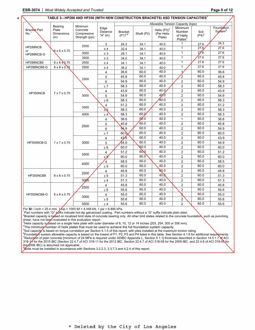
TABLE 3—HP288 AND HP350 (WITH NEW CONSTRUCTION BRACKETS) ASD TENSION CAPACITIES7
Bracket Part No.1
Bearing Plate Dimensions (in)
Minimum Concrete Compressive Strength (psi)
Edge Distance "A" (in)
Allowable Tension Capacity (kips)
Bracket (P1)2,8 Shaft (P2)
Helix (P3)3
(Per Helix Plate)
Minimum Number of Helix Plates4
Soil (P4)5
Foundation System6
HP288NCB or HP288NCB-G
6 x 6 x 0.75 2500 3 24.3 34.1 40.0 1 27.6 24.3
≥ 4 32.4 34.1 40.0 1 27.6 27.6 3000 ≥ 3 29.1 34.1 40.0 1 27.6 27.6 3500 ≥ 3 34.0 34.1 40.0 1 27.6 27.6
HP288NCB8 8 x 8 x 0.75 2500 ≥ 4 34.1 34.1 40.0 1 27.6 27.6 HP288NCB8-G 8 x 8 x 0.75 2500 ≥ 4 38.2 34.1 40.0 1 27.6 27.6
HP350NCB 7 x 7 x 0.75
2500
4 36.6 60.0 40.0 1 60.0 36.6 5 45.8 60.0 40.0 2 60.0 45.8 6 54.9 60.0 40.0 2 60.0 54.9 ≥ 7 58.3 60.0 40.0 2 60.0 58.3
3000 4 43.9 60.0 40.0 2 60.0 43.9 5 54.9 60.0 40.0 2 60.0 54.9 ≥ 6 58.3 60.0 40.0 2 60.0 58.3
3500 4 51.2 60.0 40.0 2 60.0 51.2 ≥ 5 58.3 60.0 40.0 2 60.0 58.3
4000 ≥ 4 58.3 60.0 40.0 2 60.0 58.3
HP350NCB-G 7 x 7 x 0.75
2500
4 36.6 60.0 40.0 1 60.0 36.6 5 45.8 60.0 40.0 2 60.0 45.8 6 54.9 60.0 40.0 2 60.0 54.9 ≥ 7 60.0 60.0 40.0 2 60.0 60.0
3000 4 43.9 60.0 40.0 2 60.0 43.9 5 54.9 60.0 40.0 2 60.0 54.9 ≥ 6 60.0 60.0 40.0 2 60.0 60.0
3500 4 51.2 60.0 40.0 2 60.0 51.2 ≥ 5 60.0 60.0 40.0 2 60.0 60.0
4000 4 58.5 60.0 40.0 2 60.0 58.5 ≥ 5 60.0 60.0 40.0 2 60.0 60.0
HP350NCB8 8 x 8 x 0.75 2500 4 45.8 60.0 40.0 2 60.0 45.8
≥ 5 51.3 60.0 40.0 2 60.0 51.3 3000 ≥ 4 51.3 60.0 40.0 2 60.0 51.3
HP350NCB8-G 8 x 8 x 0.75
2500 4 45.8 60.0 40.0 2 60.0 45.8 ≥ 5 55.6 60.0 40.0 2 60.0 55.6
3000 4 55.0 60.0 40.0 2 60.0 55.0 ≥ 5 55.6 60.0 40.0 2 60.0 55.6
3500 ≥ 4 55.6 60.0 40.0 2 60.0 55.6 For SI: I inch = 25.4 mm, 1 kip = 1000 lbf = 4.448 kN, 1 psi = 6.895 kPa. 1Part numbers with “G” suffix indicate hot-dip galvanized coating. Part numbers without a “G” suffix indicate plain steel. 2Bracket capacity is based on localized limit state of concrete bearing only. All other limit states related to the concrete foundation, such as punching shear, have not been evaluated in this evaluation report. 3Helix capacity is based on a single helix plate with outer diameter of 8, 10, 12 or 14 inches (203, 254, 305 or 356 mm). 4The minimum number of helix plates that must be used to achieve the full foundation system capacity. 5Soil capacity is based on torque correlation per Section 4.1.5 of this report, with piles installed at the maximum torsion rating. 6Foundation system allowable capacity is based on the lowest of P1, P2, P3 and P4 listed in this table. See Section 4.1.6 for additional requirements. 7Reduction of plain concrete [minimum of 24 MPa is required under ADIBC Appendix L, Section 5.1.1] thickness described in Section 14.5.1.7 of ACI 318-14 for the 2015 IBC (Section 22.4.7 of ACI 318-11 for the 2012 IBC, Section 22.4.7 of ACI 318-08 for the 2009 IBC, and 22.4.8 of ACI 318-05 for the 2006 IBC) is assumed not applicable. 8Bolts must be installed in accordance with Sections 3.2.2.3, 3.3.7.3 and 4.2.4 of this report.

E
ESR-3074 | M
Mechanic
Steel Minimum
Steel MiniStren
Modulus oNominal WDesign WOutside D
Inside DCross Sec
MomentRadius o
Elastic SectPlastic Sect
For SI: I inch = 2
Most Widely Acc
FIGURES
T
cal Properties
m Yield StrengthFy
mum Ultimate ngth, Fu of Elasticity, E
Wall Thickness Wall Thickness Diameter, OD Diameter, ID ctional Area, A t of Inertia, I of Gyration, r tion Modulus, S tion Modulus, Z 25.4 mm, 1 ksi =
cepted and Tru
2A AND 2B—H
TABLE 4—MEC
Un-Pla
HP288 h, 60 ksi
70 ksi
29,000 ksi0.276 in. 0.257 in. 2.875 in. 2.361 in. 2.11 in2 1.83 in4 0.93 in. 1.27 in3 1.77 in3
6.895 MPa, 1lbf
usted
P288 AND HP35
CHANICAL PRO
-corroded ain Steel
HP350
65 ksi
75 ksi
i 29,000 ksi0.340 in.0.316 in.
3.5 in. 2.868 in.3.16 in2 4.05 in4 1.13 in. 2.31 in3 3.21 in3
f-ft = 1.356 N-m,
50 NEW CONST
PERTIES OF HP
PlHP288
60 ksi
70 ksi
29,000 ksi0.276 in.0.221 in.2.839 in.2.397 in.1.82 in2 1.57 in4 0.93 in. 1.10 in3 1.52 in3
1 lbf = 4.448 N.
TRUCTION BRA
P288 AND HP35
After 50 lain Steel
HP350
65 ksi
75 ksi
29,000 k0.340 in0.280 in3.464 in2.904 in2.80 in2
3.58 in4
1.13 in.2.07 in3
2.85 in3
ACKET ASSEMB
50 SHAFTS
Year Corrosion Hot-
HP28
60 ks
70 ks
ksi 29,000 n. 0.276 n. 0.247 n. 2.865 n. 2.371 2 2.03 i4 1.76 i. 0.93 i3 1.23 i3 1.70 i
Pag
BLIES
Loss -dip Galvanized S88 HP
si 65
si 75
ksi 29,0in. 0.34in. 0.3in. 3.4in. 2.8n2 3.0n4 3.9n. 1.1n3 2.2n3 3.1
ge 10 of 12
Steel P350
5 ksi
5 ksi
000 ksi 40 in. 06 in. 90 in. 78 in.
06 in2 91 in4 13 in. 24 in3 11 in3

ESR-3074 | Most Widely Accepted and Trusted Page 11 of 12
TABLE 5—HP288 AND HP350 LEAD AND EXTENSION ASD TENSION AND COMPRESSION CAPACITIES1,6 Lead/Extension Part No.
Net Shaft Length "L" (in)
Helix Diameter (in) (P2)2 Shaft Comp. (kips)
(P2) Shaft Ten. (kips)
(P3)3 Helix (kips)
Kt (ft-1)
Shaft Torsion Rating4 (lbf-ft)
(P4)5 Torque Correlated Soil Capacity (kips)
A B C D
Comp. Ten.
HP288L5H8-3850 60 8 -- -- -- 60.0 34.1 40.0 9 7898 35.5 27.6 HP288L5H0-3850 60 10 -- -- -- 60.0 34.1 40.0 9 7898 35.5 27.6 HP288L5H2-3850 60 12 -- -- -- 60.0 34.1 40.0 9 7898 35.5 27.6 HP288L5H4-3850 60 14 -- -- 60.0 34.1 40.0 9 7898 35.5 27.6 HP288L5H80-3850 60 8 10 -- -- 60.0 34.1 60.0 9 7898 35.5 27.6 HP288L5H02-3850 60 10 12 -- -- 60.0 34.1 60.0 9 7898 35.5 27.6 HP288L5H24-3850 60 12 14 -- 60.0 34.1 60.0 9 7898 35.5 27.6 HP288L7H8-3850 84 8 -- -- -- 60.0 34.1 40.0 9 7898 35.5 27.6 HP288L7H0-3850 84 10 -- -- -- 60.0 34.1 40.0 9 7898 35.5 27.6 HP288L7H2-3850 84 12 -- -- -- 60.0 34.1 40.0 9 7898 35.5 27.6 HP288L7H4-3850 84 14 -- -- 60.0 34.1 40.0 9 7898 35.5 27.6 HP288L7H80-3850 84 8 10 -- -- 60.0 34.1 60.0 9 7898 35.5 27.6 HP288L7H02-3850 84 10 12 -- -- 60.0 34.1 60.0 9 7898 35.5 27.6 HP288L7H24-3850 84 12 14 -- -- 60.0 34.1 60.0 9 7898 35.5 27.6 HP288L7H802-3850 84 8 10 12 -- 60.0 34.1 60.0 9 7898 35.5 27.6 HP288L7H024-3850 84 10 12 14 -- 60.0 34.1 60.0 9 7898 35.5 27.6 HP288L0H80-3850 120 8 10 -- -- 60.0 34.1 60.0 9 7898 35.5 27.6 HP288L0H02-3850 120 10 12 -- -- 60.0 34.1 60.0 9 7898 35.5 27.6 HP288L0H24-3850 120 12 14 -- -- 60.0 34.1 60.0 9 7898 35.5 27.6 HP288L0H802-3850 120 8 10 12 -- 60.0 34.1 60.0 9 7898 35.5 27.6 HP288L0H024-3850 120 10 12 14 -- 60.0 34.1 60.0 9 7898 35.5 27.6 HP288L0H8024-3850 120 8 10 12 14 60.0 34.1 60.0 9 7898 35.5 27.6 HP288E3H4-3850 30 14 -- -- -- 60.0 34.1 40.0 9 7898 35.5 27.6 HP288E4H4-3850 42 14 -- -- -- 60.0 34.1 40.0 9 7898 35.5 27.6 HP288E5H4-3850 54 14 -- -- -- 60.0 34.1 40.0 9 7898 35.5 27.6 HP288E7H4-3850 78 14 -- -- -- 60.0 34.1 40.0 9 7898 35.5 27.6 HP288E0H4-3850 114 14 -- -- -- 60.0 34.1 40.0 9 7898 35.5 27.6 HP288E7H44-3850 78 14 14 -- -- 60.0 34.1 60.0 9 7898 35.5 27.6 HP288E0H44-3850 114 14 14 -- -- 60.0 34.1 60.0 9 7898 35.5 27.6 HP288E3 30 -- -- -- -- 60.0 34.1 NA 9 7898 35.5 27.6 HP288E5 54 -- -- -- -- 60.0 34.1 NA 9 7898 35.5 27.6 HP288E7 78 -- -- -- -- 60.0 34.1 NA 9 7898 35.5 27.6 HP288E0 114 -- -- -- -- 60.0 34.1 NA 9 7898 35.5 27.6 HP350LS5H8-3850 60 8 -- -- -- 60.0 60.0 40.0 7 17500 40.0 40.0 HP350LS5H0-3850 60 10 -- -- -- 60.0 60.0 40.0 7 17500 40.0 40.0 HP350LS5H2-3850 60 12 -- -- -- 60.0 60.0 40.0 7 17500 40.0 40.0 HP350LS5H4-3850 60 14 -- -- 60.0 60.0 40.0 7 17500 40.0 40.0 HP350LS5H80-3850 60 8 10 -- -- 60.0 60.0 60.0 7 17500 60.0 60.0 HP350LS5H02-3850 60 10 12 -- -- 60.0 60.0 60.0 7 17500 60.0 60.0 HP350LS5H24-3850 60 12 14 -- 60.0 60.0 60.0 7 17500 60.0 60.0 HP350LS7H8-3850 84 8 -- -- -- 60.0 60.0 40.0 7 17500 40.0 40.0 HP350LS7H0-3850 84 10 -- -- -- 60.0 60.0 40.0 7 17500 40.0 40.0 HP350LS7H2-3850 84 12 -- -- -- 60.0 60.0 40.0 7 17500 40.0 40.0 HP350LS7H4-3850 84 14 -- -- 60.0 60.0 40.0 7 17500 40.0 40.0 HP350LS7H80-3850 84 8 10 -- -- 60.0 60.0 60.0 7 17500 60.0 60.0 HP350LS7H02-3850 84 10 12 -- -- 60.0 60.0 60.0 7 17500 60.0 60.0 HP350LS7H24-3850 84 12 14 -- -- 60.0 60.0 60.0 7 17500 60.0 60.0 HP350LS7H802-3850 84 8 10 12 -- 60.0 60.0 60.0 7 17500 60.0 60.0 HP350LS7H024-3850 84 10 12 14 -- 60.0 60.0 60.0 7 17500 60.0 60.0 HP350LS0H80-3850 120 8 10 -- -- 60.0 60.0 60.0 7 17500 60.0 60.0 HP350LS0H02-3850 120 10 12 -- -- 60.0 60.0 60.0 7 17500 60.0 60.0 HP350LS0H24-3850 120 12 14 -- -- 60.0 60.0 60.0 7 17500 60.0 60.0 HP350LS0H802-3850 120 8 10 12 -- 60.0 60.0 60.0 7 17500 60.0 60.0 HP350LS0H024-3850 120 10 12 14 -- 60.0 60.0 60.0 7 17500 60.0 60.0 HP350LS0H8024-3850 120 8 10 12 14 60.0 60.0 60.0 7 17500 60.0 60.0 HP350E5H4-3850 60 14 -- -- -- 60.0 60.0 60.0 7 17500 60.0 60.0 HP350E7H4-3850 84 14 -- -- -- 60.0 60.0 60.0 7 17500 60.0 60.0 HP350E0H4-3850 120 14 -- -- -- 60.0 60.0 60.0 7 17500 60.0 60.0 HP350E7H44-3850 84 14 14 -- -- 60.0 60.0 60.0 7 17500 60.0 60.0 HP350E0H44-3850 120 14 14 -- -- 60.0 60.0 60.0 7 17500 60.0 60.0 HP350E3 36 -- -- -- -- 60.0 60.0 NA 7 17500 60.0 60.0 HP350E4 48 -- -- -- -- 60.0 60.0 NA 7 17500 60.0 60.0 HP350E5 60 -- -- -- -- 60.0 60.0 NA 7 17500 60.0 60.0 HP350E7 84 -- -- -- -- 60.0 60.0 NA 7 17500 60.0 60.0 HP350E0 120 -- -- -- -- 60.0 60.0 NA 7 17500 60.0 60.0
For SI: I inch = 25.4 mm, 1 kip = 1000 lbf = 4.448 kN, 1lbf-ft = 1.356 N-m. NA = not applicable 1Part numbers with “G” suffix indicate hot-dip galvanized coating. Part numbers without a “G” suffix indicate plain steel. 2Shaft compression capacity (P2) is based on fully braced conditions as described in Section 4.1.3. 3Helix capacity (P3) is applicable to both tension and compression loading and is based on a 40 kip allowable capacity for single helix lead sections and 60 kip for multi-helix lead sections or helical extensions. 4Shaft torsion rating is the maximum torsion that can be applied to the shaft during the helical pile installation. 5Torque correlated soil capacity (P4) is applicable to both tension and compression loading and is based on torque correlation per Section 4.1.5, with piles installed at the maximum torsion rating. 6For piles with extension(s), shaft coupling(s) must be installed in accordance with Sections 3.2.1 and 4.2.2 of this report.
E ESR-3074 | MMost Widely Acc
FIGURE 3—
FIGURE 4—
cepted and Tru
—TYPICAL HP28
—TYPICAL HP35
usted
88 SHAFT LEAD
50 SHAFT LEAD
D AND EXTENS
D AND EXTENS
SION SECTIONS
SION SECTIONS
S AND HELIX PL
S AND HELIX PL
Pag
LATES
LATES
ge 12 of 12