civil reference data guide
DESCRIPTION
ererTRANSCRIPT
Civil Reference Data Guide
April 2015
Version 2014 R1 (10.1)
DSP3D-PE-200133A

Civil Reference Data Guide 2
Copyright
Copyright © 2012-2015 Intergraph® Corporation. All Rights Reserved. Intergraph is part of Hexagon.
Including software, file formats, and audiovisual displays; may be used pursuant to applicable software license agreement; contains confidential and proprietary information of Intergraph and/or third parties which is protected by copyright law, trade secret law, and international treaty, and may not be provided or otherwise made available without proper authorization from Intergraph Corporation.
Portions of this software are owned by Spatial Corp. © 1986-2014. All Rights Reserved.
Portions of the user interface copyright 2012-2014 Telerik AD.
U.S. Government Restricted Rights Legend
Use, duplication, or disclosure by the government is subject to restrictions as set forth below. For civilian agencies: This was developed at private expense and is "restricted computer software" submitted with restricted rights in accordance with subparagraphs (a) through (d) of the Commercial Computer Software - Restricted Rights clause at 52.227-19 of the Federal Acquisition Regulations ("FAR") and its successors, and is unpublished and all rights are reserved under the copyright laws of the United States. For units of the Department of Defense ("DoD"): This is "commercial computer software" as defined at DFARS 252.227-7014 and the rights of the Government are as specified at DFARS 227.7202-3.
Unpublished - rights reserved under the copyright laws of the United States.
Intergraph Corporation 305 Intergraph Way Madison, AL 35758
Documentation
Documentation shall mean, whether in electronic or printed form, User's Guides, Installation Guides, Reference Guides, Administrator's Guides, Customization Guides, Programmer's Guides, Configuration Guides and Help Guides delivered with a particular software product.
Other Documentation
Other Documentation shall mean, whether in electronic or printed form and delivered with software or on Intergraph Smart Support, SharePoint, or box.net, any documentation related to work processes, workflows, and best practices that is provided by Intergraph as guidance for using a software product.
Terms of Use
a. Use of a software product and Documentation is subject to the End User License Agreement ("EULA") delivered with the software product unless the Licensee has a valid signed license for this software product with Intergraph Corporation. If the Licensee has a valid signed license for this software product with Intergraph Corporation, the valid signed license shall take precedence and govern the use of this software product and Documentation. Subject to the terms contained within the applicable license agreement, Intergraph Corporation gives Licensee permission to print a reasonable number of copies of the Documentation as defined in the applicable license agreement and delivered with the software product for Licensee's internal, non-commercial use. The Documentation may not be printed for resale or redistribution.
b. For use of Documentation or Other Documentation where end user does not receive a EULA or does not have a valid license agreement with Intergraph, Intergraph grants the Licensee a non-exclusive license to use the Documentation or Other Documentation for Licensee’s internal non-commercial use. Intergraph Corporation gives Licensee permission to print a reasonable number of copies of Other Documentation for Licensee’s internal, non-commercial. The Other Documentation may not be printed for resale or redistribution. This license contained in this subsection b) may be terminated at any time and for any reason by Intergraph Corporation by giving written notice to Licensee.
Disclaimer of Warranties
Except for any express warranties as may be stated in the EULA or separate license or separate terms and conditions, Intergraph Corporation disclaims any and all express or implied warranties including, but not limited to the implied warranties of merchantability and fitness for a particular purpose and nothing stated in, or implied by, this document or its contents shall be considered or deemed a modification or amendment of such disclaimer. Intergraph believes the information in this publication is accurate as of its publication date.
The information and the software discussed in this document are subject to change without notice and are subject to applicable technical product descriptions. Intergraph Corporation is not responsible for any error that may appear in this document.
The software, Documentation and Other Documentation discussed in this document are furnished under a license and may be used or copied only in accordance with the terms of this license. THE USER OF THE SOFTWARE IS EXPECTED TO MAKE THE FINAL EVALUATION AS TO THE USEFULNESS OF THE SOFTWARE IN HIS OWN ENVIRONMENT.
Civil Reference Data Guide 3
Intergraph is not responsible for the accuracy of delivered data including, but not limited to, catalog, reference and symbol data. Users should verify for themselves that the data is accurate and suitable for their project work.
Limitation of Damages
IN NO EVENT WILL INTERGRAPH CORPORATION BE LIABLE FOR ANY DIRECT, INDIRECT, CONSEQUENTIAL INCIDENTAL, SPECIAL, OR PUNITIVE DAMAGES, INCLUDING BUT NOT LIMITED TO, LOSS OF USE OR PRODUCTION, LOSS OF REVENUE OR PROFIT, LOSS OF DATA, OR CLAIMS OF THIRD PARTIES, EVEN IF INTERGRAPH CORPORATION HAS BEEN ADVISED OF THE POSSIBILITY OF SUCH DAMAGES.
UNDER NO CIRCUMSTANCES SHALL INTERGRAPH CORPORATION’S LIABILITY EXCEED THE AMOUNT THAT INTERGRAPH CORPORATION HAS BEEN PAID BY LICENSEE UNDER THIS AGREEMENT AT THE TIME THE CLAIM IS MADE. EXCEPT WHERE PROHIBITED BY APPLICABLE LAW, NO CLAIM, REGARDLESS OF FORM, ARISING OUT OF OR IN CONNECTION WITH THE SUBJECT MATTER OF THIS DOCUMENT MAY BE BROUGHT BY LICENSEE MORE THAN TWO (2) YEARS AFTER THE EVENT GIVING RISE TO THE CAUSE OF ACTION HAS OCCURRED.
IF UNDER THE LAW RULED APPLICABLE ANY PART OF THIS SECTION IS INVALID, THEN INTERGRAPH LIMITS ITS LIABILITY TO THE MAXIMUM EXTENT ALLOWED BY SAID LAW.
Export Controls
Intergraph Corporation’s software products and any third-party Software Products obtained from Intergraph Corporation, its subsidiaries, or distributors (including any Documentation, Other Documentation or technical data related to these products) are subject to the export control laws and regulations of the United States. Diversion contrary to U.S. law is prohibited. These Software Products, and the direct product thereof, must not be exported or re-exported, directly or indirectly (including via remote access) under the following circumstances:
a. To Cuba, Iran, North Korea, Sudan, or Syria, or any national of these countries.
b. To any person or entity listed on any U.S. government denial list, including but not limited to, the U.S. Department of Commerce Denied Persons, Entities, and Unverified Lists, http://www.bis.doc.gov/complianceandenforcement/liststocheck.htm, the U.S. Department of Treasury Specially Designated Nationals List, http://www.treas.gov/offices/enforcement/ofac/, and the U.S. Department of State Debarred List, http://www.pmddtc.state.gov/compliance/debar.html.
c. To any entity when Licensee knows, or has reason to know, the end use of the Software Product is related to the design, development, production, or use of missiles, chemical, biological, or nuclear weapons, or other un-safeguarded or sensitive nuclear uses.
d. To any entity when Licensee knows, or has reason to know, that an illegal reshipment will take place.
Any questions regarding export or re-export of these Software Products should be addressed to Intergraph Corporation’s Export Compliance Department, Huntsville, Alabama 35894, USA.
Trademarks
Intergraph, the Intergraph logo, PDS, SmartPlant, FrameWorks, I-Sketch, SmartMarine, IntelliShip, ISOGEN, SmartSketch, SPOOLGEN, SupportManager, SupportModeler, Sapphire, and Intergraph Smart are trademarks or registered trademarks of Intergraph Corporation or its subsidiaries in the United States and other countries. Hexagon and the Hexagon logo are registered trademarks of Hexagon AB or its subsidiaries. Microsoft and Windows are registered trademarks of Microsoft Corporation. ACIS is a registered trademark of SPATIAL TECHNOLOGY, INC. Infragistics, Presentation Layer Framework, ActiveTreeView Ctrl, ProtoViewCtl, ActiveThreed Ctrl, ActiveListBar Ctrl, ActiveSplitter, ActiveToolbars Ctrl, ActiveToolbars Plus Ctrl, and ProtoView are trademarks of Infragistics, Inc. Incorporates portions of 2D DCM, 3D DCM, and HLM by Siemens Product Lifecycle Management Software III (GB) Ltd. All rights reserved. Gigasoft is a registered trademark, and ProEssentials a trademark of Gigasoft, Inc. VideoSoft and VXFlexGrid are either registered trademarks or trademarks of ComponentOne LLC 1991-2013, All rights reserved. Oracle, JD Edwards, PeopleSoft, and Retek are registered trademarks of Oracle Corporation and/or its affiliates. Tribon is a trademark of AVEVA Group plc. Alma and act/cut are trademarks of the Alma company. Other brands and product names are trademarks of their respective owners.
Civil Reference Data Guide 4
Contents Preface .......................................................................................................................................................... 5
What's New in Civil Reference Data .......................................................................................................... 6
Civil Reference Data Overview ................................................................................................................... 7
Bulkload Files and the Civil Catalog ......................................................................................................... 8
Code List Workbook ................................................................................................................................ 8 Common Workbook ................................................................................................................................ 8 Trench Cross-Sections Workbook .......................................................................................................... 8 Trench General Composition Workbook ............................................................................................... 10
Trench Composition Worksheet ..................................................................................................... 10 Trench Type Worksheets ............................................................................................................... 11 Trench Turn Part Worksheet .......................................................................................................... 12
Civil Symbols ............................................................................................................................................. 14
Trench Symbol U .................................................................................................................................. 20 Trench Symbol 2W1F ........................................................................................................................... 20 Trench Symbol 2W2F ........................................................................................................................... 21 Trench Symbol V................................................................................................................................... 21 Trench Symbol Box ............................................................................................................................... 22
Index ........................................................................................................................................................... 23
Civil Reference Data Guide 5
This document is a reference data guide for the Intergraph SmartTM 3D Civil task. The purpose of this document is to describe the reference data delivered with the software for this task.
Reference data includes both catalog data and specification data. Catalog data includes the parts that you place in the model, such as piping components and equipment. Specification data includes the rules that govern how those parts are placed and connected.
Documentation Comments
We welcome comments or suggestions about this documentation. You can send us an email at: [email protected].
Documentation updates for supported software versions are available from https://smartsupport.intergraph.com (https://smartsupport.intergraph.com).
Preface
Civil Reference Data Guide 6
The following changes have been made to the Civil reference data.
Version 2013 (10.0)
Civil reference data is new for this release.
What's New in Civil Reference Data
Civil Reference Data Guide 7
S E C T I O N 1
Each organization using the software requires customized reference data such as rules, catalog items, and symbols to meet the organization's exact needs. Customized rules control how and when the catalog items and symbols are used in the model.
Before working with civil reference data, you must familiarize yourself with the way that the software handles reference data in general. If you have not already done so, read and understand the following important concepts and procedures described in the Reference Data Guide, 2D Symbols User's Guide, and 2D Symbols Reference Data Guide.
Reference data types
Using Excel workbooks to configure reference data
Using the bulkload modes
Creating 2D symbols using the 2D Symbols utility
Creating a graphical preview using a symbol icon bitmap file
This reference data guide describes the example civil reference data delivered with the software.
Civil Reference Data Overview
Civil Reference Data Guide 8
S E C T I O N 2
Bulkload files are used to add reference data to the catalog. The reference data includes codelist values, rule ProgIDs, symbol file locations, and default values for rule and symbol parameters. The relationships between different types of reference data are also established.
Each bulkload file is delivered with default values that can be customized. For more information about bulkloading, see the Reference Data Guide.
Code List Workbook The AllCodelists.xls Workbook defines the acceptable values for attributes in the catalog. The workbook is delivered to the [Product Folder]\CatalogData\BulkLoad\DataFiles folder and is bulkloaded into the catalog.
The Civil task uses part classes defined on the PartClassType worksheet:
TrenchTypeClass
TrenchCompositionClass
TrenchTurnPartClass
Common Workbook The AllCommon.xls workbook defines standard catalog properties and attributes, such as allowable materials, wall thicknesses, pipe stock, and outfitting cross section mounting faces and load points. The workbook is delivered to the [Product Folder]\CatalogData\BulkLoad\DataFiles folder and is bulkloaded into the catalog.
The Civil task uses allowable materials defined on the Material worksheet. For more information, see Material Sheet in the Reference Data Guide.
Trench Cross-Sections Workbook The Trench_CrossSections.xls workbook defines standard trench and ditch cross-sections used by the Civil task. The workbook is delivered to the [Product Folder]\CatalogData\BulkLoad\DataFiles\ folder and is bulkloaded into the catalog.
The workbook is delivered with a worksheet for each type of cross-section. Each worksheet defines a cross-section class, the corresponding 2D symbol file, and default parameters in the catalog.
Your reference data administrator can modify or add parameters to the delivered cross-sections. You can also add new cross-sections by creating new part classes on new worksheets and by creating new symbols.
Bulkload Files and the Civil Catalog
Bulkload Files and the Civil Catalog
Civil Reference Data Guide 9
Definition Section
Defines attributes that apply to the entire cross section type.
PartClassType - Class type CrossSectionClass as defined on the PartClassTypes sheet of the AllCodeLists.xls file. Do not modify this property.
SymbolDefinition - 2D symbol file associated with the cross-section type. 2D symbol files are delivered to the [Reference Data Folder]\SharedContent folder. For more information, see Civil Symbols (on page 14).
SymbolIcon - Specifies a graphic file for the part class. You can view this graphic in the Catalog task or on the Properties dialog box in the Civil task in the software.
UserClassName - Cross section type defined internally by the software and displayed in the Catalog task browser in the software.
ReferenceStandard - Standards organization or shape library for the cross section type, as defined on the ReferenceStandard worksheet.
oa:[parameter name] - Occurrence attribute that places the named catalog attribute on the Trench Run Properties dialog box in the Civil task. Each parameter also appears in the Head section and corresponding to a parameter in the 2D symbol file defined by SymbolDefinition.
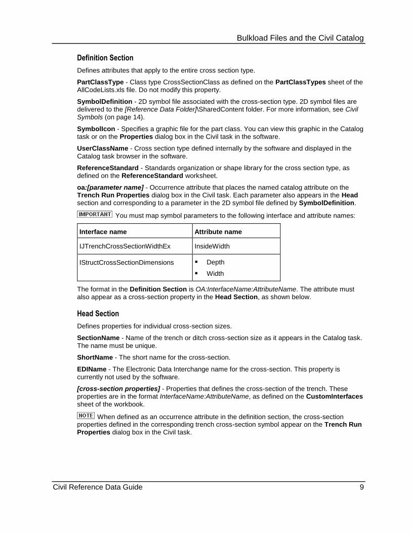
You must map symbol parameters to the following interface and attribute names:
Interface name Attribute name
IJTrenchCrossSectionWidthEx InsideWidth
IStructCrossSectionDimensions Depth
Width
The format in the Definition Section is OA:InterfaceName:AttributeName. The attribute must also appear as a cross-section property in the Head Section, as shown below.
Head Section
Defines properties for individual cross-section sizes.
SectionName - Name of the trench or ditch cross-section size as it appears in the Catalog task. The name must be unique.
ShortName - The short name for the cross-section.
EDIName - The Electronic Data Interchange name for the cross-section. This property is currently not used by the software.
[cross-section properties] - Properties that defines the cross-section of the trench. These properties are in the format InterfaceName:AttributeName, as defined on the CustomInterfaces sheet of the workbook.
When defined as an occurrence attribute in the definition section, the cross-section properties defined in the corresponding trench cross-section symbol appear on the Trench Run Properties dialog box in the Civil task.
Bulkload Files and the Civil Catalog
Civil Reference Data Guide 10
Trench General Composition Workbook The Trench_General_Composition.xls workbook defines standard trench and ditch properties used by the Civil task. The workbook is delivered to the [Product Folder]\CatalogData\BulkLoad\DataFiles\ folder and is bulkloaded into the catalog.
The workbook is delivered with a worksheet for trench composition, turn parts, and each trench type. Each worksheet defines a class and properties in the catalog.
Definition Section
Defines attributes that apply to the entire trench class.
PartClassType - Class type as defined on the PartClassTypes sheet of the AllCodeLists.xls file. For more information, see Code List Workbook (on page 8).
UserClassName - Trench type defined internally by the software and displayed in the Catalog task browser in the software.
Trench Composition Worksheet (on page 10)
Trench Type Worksheets (on page 11)
Trench Turn Part Worksheet (on page 12)
Trench Composition Worksheet
The TrenchComposition worksheet in the Trench_General_Composition.xls workbook defines the material types and grades used by different parts of the trench cross-section. This worksheet defines the TrenchCompositionClass.
Head Section
Defines properties for individual sections of a trench type. Each section is defined as a contour in the symbol file.
Name - The name of the trench contour as the contour appears in the Catalog task. The name must be unique.
TrenchName - The name of the trench, as defined within a trench type worksheet. For more information, see Trench Type Worksheets (on page 11).
GroupName - The name of the contour in the symbol file, such as LeftWall, RightWall, or Footing.
GroupType - The contour type. Type 1 for trench wall, 2 for trench slab, or 3 for trench footing.
ThicknessProjection - The vertical thickness projection of the trench slab or footing contour with respect to the slope of the path.
DefaultMaterial - The material used for the GroupName, as defined in the AllCommon.xls workbook. Each contour can use a different material. For more information, see Common Workbook (on page 8).
DefaultMaterialGrade - The material grade used for the GroupName, as defined in the AllCommon.xls workbook. Each contour can use a different material grade. For more information, see Common Workbook (on page 8).
Bulkload Files and the Civil Catalog
Civil Reference Data Guide 11
Description - A description of the trench material composition.
Each trench type has one cross-section PartClass with a set of GroupName values for the contours of the symbol file.
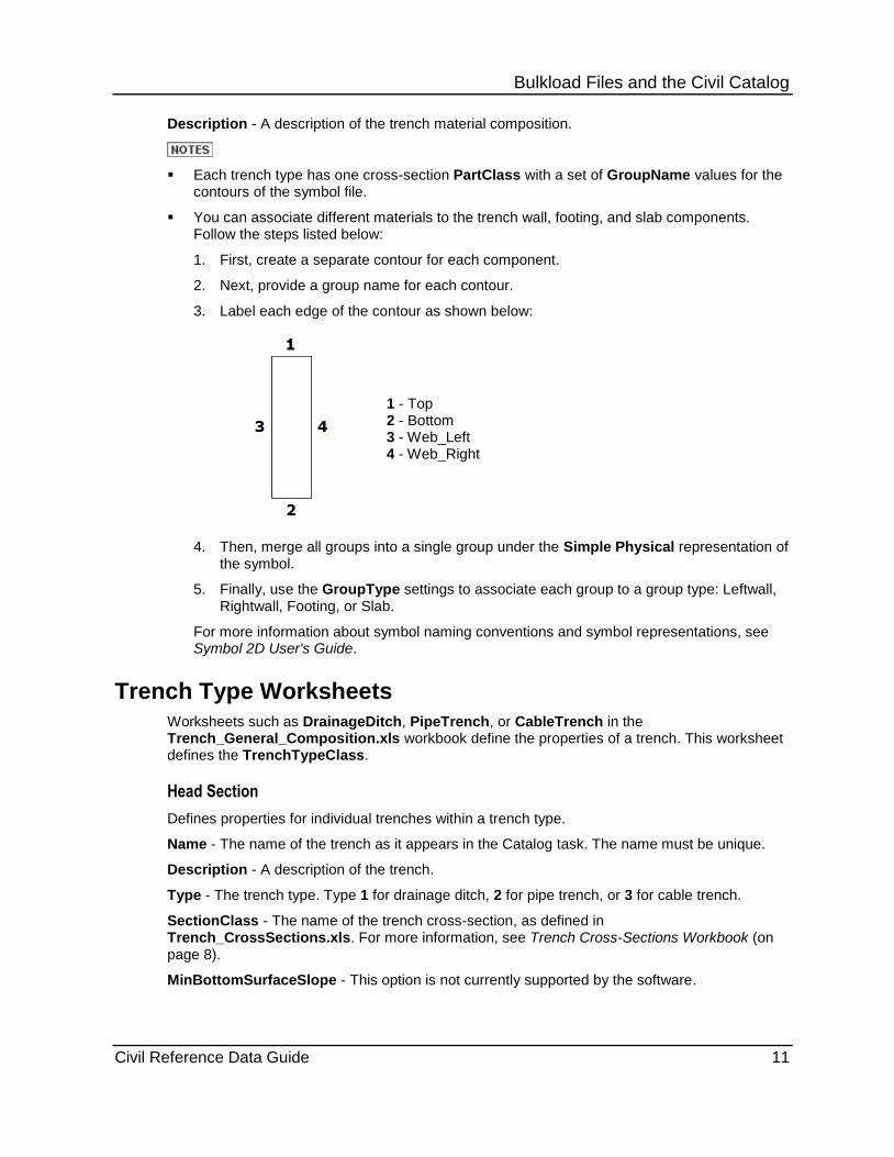
You can associate different materials to the trench wall, footing, and slab components. Follow the steps listed below:
1. First, create a separate contour for each component.
2. Next, provide a group name for each contour.
3. Label each edge of the contour as shown below:
1 - Top 2 - Bottom 3 - Web_Left 4 - Web_Right
4. Then, merge all groups into a single group under the Simple Physical representation of the symbol.
5. Finally, use the GroupType settings to associate each group to a group type: Leftwall, Rightwall, Footing, or Slab.
For more information about symbol naming conventions and symbol representations, see Symbol 2D User's Guide.
Trench Type Worksheets
Worksheets such as DrainageDitch, PipeTrench, or CableTrench in the Trench_General_Composition.xls workbook define the properties of a trench. This worksheet defines the TrenchTypeClass.
Head Section
Defines properties for individual trenches within a trench type.
Name - The name of the trench as it appears in the Catalog task. The name must be unique.
Description - A description of the trench.
Type - The trench type. Type 1 for drainage ditch, 2 for pipe trench, or 3 for cable trench.
SectionClass - The name of the trench cross-section, as defined in Trench_CrossSections.xls. For more information, see Trench Cross-Sections Workbook (on page 8).
MinBottomSurfaceSlope - This option is not currently supported by the software.

Bulkload Files and the Civil Catalog
Civil Reference Data Guide 12
TrenchTurnPartRule - The rule used for a turn with the trench, as defined in the TrenchTurnPart worksheet. For more information, see Trench Turn Part Worksheet (on page 12).
CustomProgram - The name of a custom program used to create a solid for the trench, in the format DLLName.ProgID.
Trench Turn Part Worksheet
The TrenchTurnPart worksheet in the Trench_General_Composition.xls workbook defines the properties used by a turn feature in the trench. This worksheet defines the TrenchTurnPartClass.
Head Section
Defines properties for individual turn features. Each section is defined as a contour in the symbol file.
Name - The name of the turn feature as the feature appears in the Catalog task. The name must be unique.
Description - A description of the turn feature.
1 - Outside Chamfer Y
2 - Outside Chamfer X
3 - Path Direction
4 - Projection Y
5 - Projection X
6 - Inside Chamfer Y
7 - Inside Chamfer X
8 - Included Angle
ProjectionX - The inside length of the turn feature along the local X axis of the trench path.
ProjectionY - The inside length of the turn feature along the local Y axis of the trench path.
AngleMin - The minimum included angle of the chamfer.
AngleMax - The maximum included angle of the chamfer.
InsideChamfer - The presence of an inside chamfer. Type 1 to create an inside chamfer. Type 0 if no inside chamfer exists.
InsideChamferX - The local X-component of the length of the inside chamfer along the path of the turn.
InsideChamferY - The local Y-component of the length of the inside chamfer along the path of the turn.
Bulkload Files and the Civil Catalog
Civil Reference Data Guide 13
OutsideChamfer - The presence of an outside chamfer. Type 1 to create an outside chamfer. Type 0 if no outside chamfer exists.
OutsideChamferX - The local X-component of the length of the outside chamfer along the path of the turn.
OutsideChamferY - The local Y-component of the length of the outside chamfer along the path of the turn.
Civil Reference Data Guide 14
S E C T I O N 3
Civil symbols provide the geometric representations of Civil objects placed in the model. You can modify the geometry and parameters of the symbols. The symbols are delivered as 2D symbol files for trenches and ditches.
Symbol icon bitmap files are also delivered for graphical previews that appear in the Catalog task and in properties dialog boxes.
You can use any shape consisting of four straight lines forming a closed contour as the symbol.
The symbols and symbol icons are delivered to [Reference Data Folder]\SharedContent\CrossSections. The symbols are also bulkloaded into the catalog. For more information, see Trench Cross-Sections Workbook (on page 8).
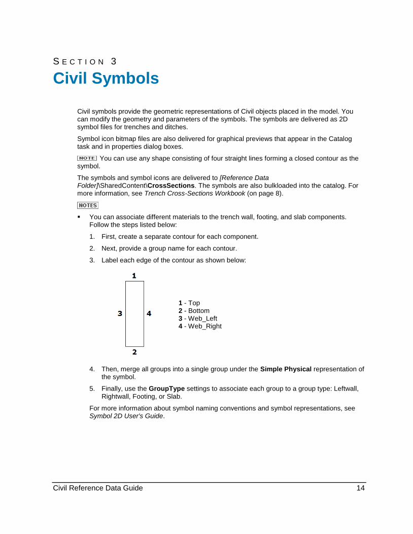
You can associate different materials to the trench wall, footing, and slab components. Follow the steps listed below:
1. First, create a separate contour for each component.
2. Next, provide a group name for each contour.
3. Label each edge of the contour as shown below:
1 - Top 2 - Bottom 3 - Web_Left 4 - Web_Right
4. Then, merge all groups into a single group under the Simple Physical representation of the symbol.
5. Finally, use the GroupType settings to associate each group to a group type: Leftwall, Rightwall, Footing, or Slab.
For more information about symbol naming conventions and symbol representations, see Symbol 2D User's Guide.
Civil Symbols

Civil Symbols
Civil Reference Data Guide 15
Symbol Requirement
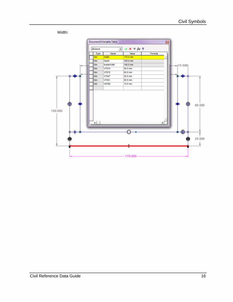
Each civil symbol cross-section must have a representation named DrivenDimensions in the respective 2D symbol file of the cross-section containing Width, Depth, and InsideDepth parameters. The example defines the DrivenDimensions for a U_Shape trench cross-section.
1. Define the three new dimensions using the Place a Dimension Between Two Elements or Key Points from the Distance Between command. For more information, see Symbol 2D User's Guide. You can select the points or the lines. The new dimensions are shown in red in the graphic below.
2. Name the new dimensions with respect to their attribute names in the catalog. For more information, see Trench Cross-Sections Workbook (on page 8).
Civil Symbols
Civil Reference Data Guide 16
Width:

Civil Symbols
Civil Reference Data Guide 17
Depth:
Civil Symbols
Civil Reference Data Guide 18
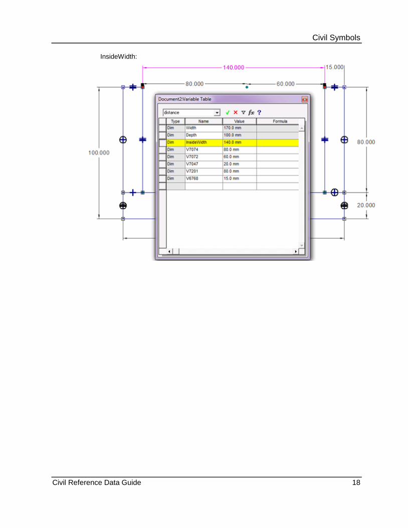
InsideWidth:
Civil Symbols
Civil Reference Data Guide 19
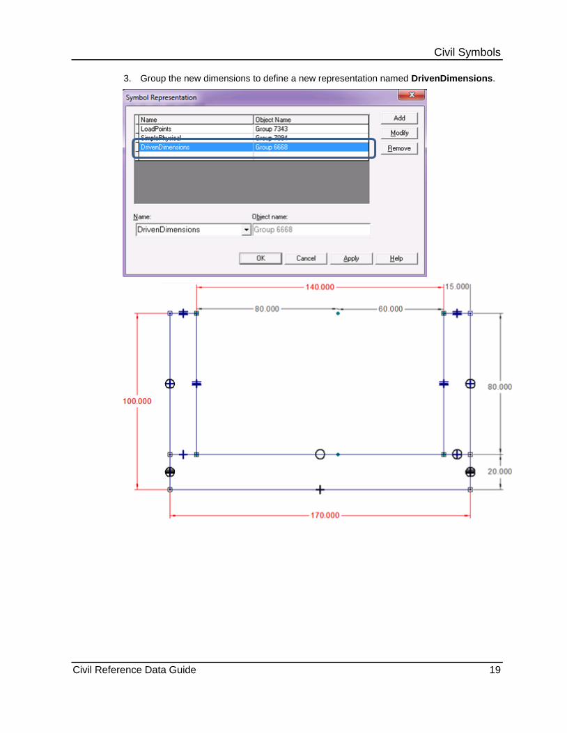
3. Group the new dimensions to define a new representation named DrivenDimensions.
Civil Symbols
Civil Reference Data Guide 20
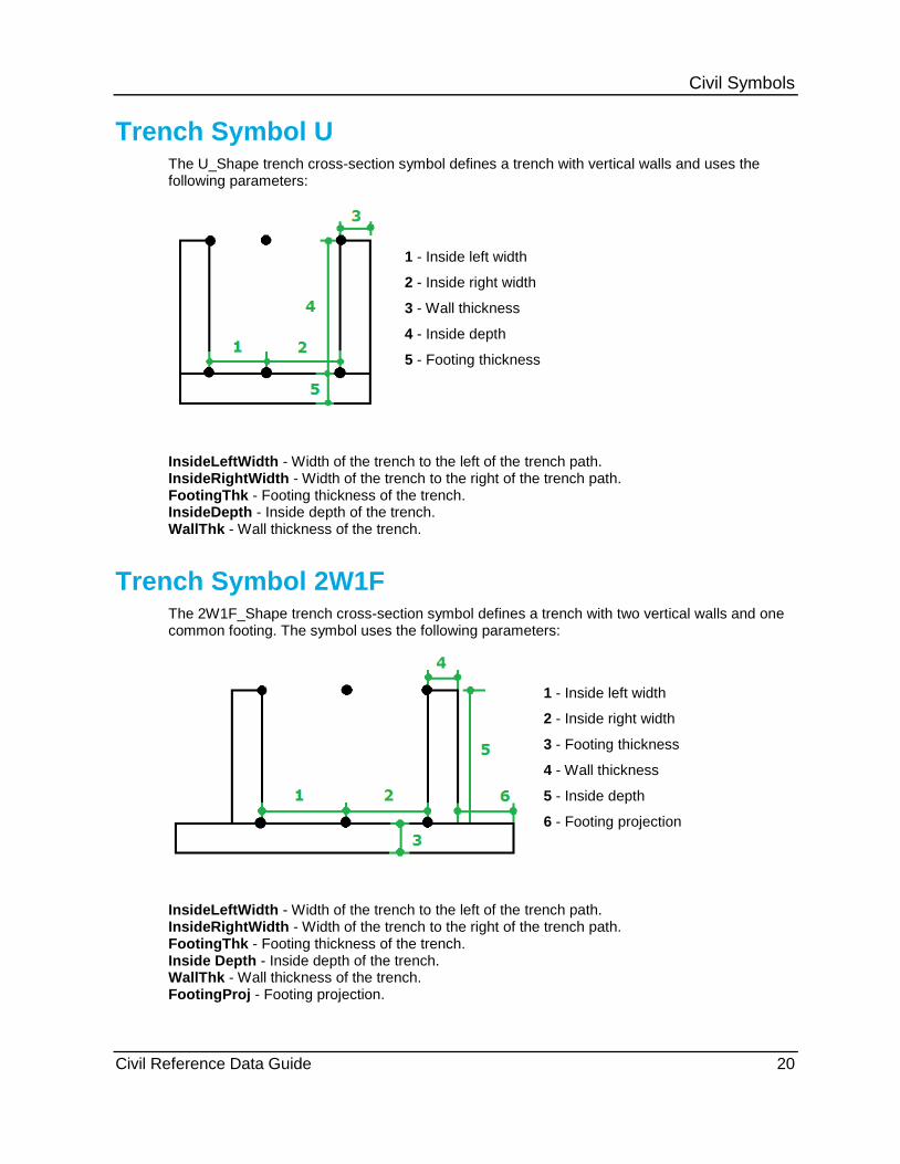
Trench Symbol U The U_Shape trench cross-section symbol defines a trench with vertical walls and uses the following parameters:
1 - Inside left width
2 - Inside right width
3 - Wall thickness
4 - Inside depth
5 - Footing thickness
InsideLeftWidth - Width of the trench to the left of the trench path. InsideRightWidth - Width of the trench to the right of the trench path. FootingThk - Footing thickness of the trench. InsideDepth - Inside depth of the trench. WallThk - Wall thickness of the trench.
Trench Symbol 2W1F The 2W1F_Shape trench cross-section symbol defines a trench with two vertical walls and one common footing. The symbol uses the following parameters:
1 - Inside left width
2 - Inside right width
3 - Footing thickness
4 - Wall thickness
5 - Inside depth
6 - Footing projection
InsideLeftWidth - Width of the trench to the left of the trench path. InsideRightWidth - Width of the trench to the right of the trench path. FootingThk - Footing thickness of the trench. Inside Depth - Inside depth of the trench. WallThk - Wall thickness of the trench. FootingProj - Footing projection.
Civil Symbols
Civil Reference Data Guide 21
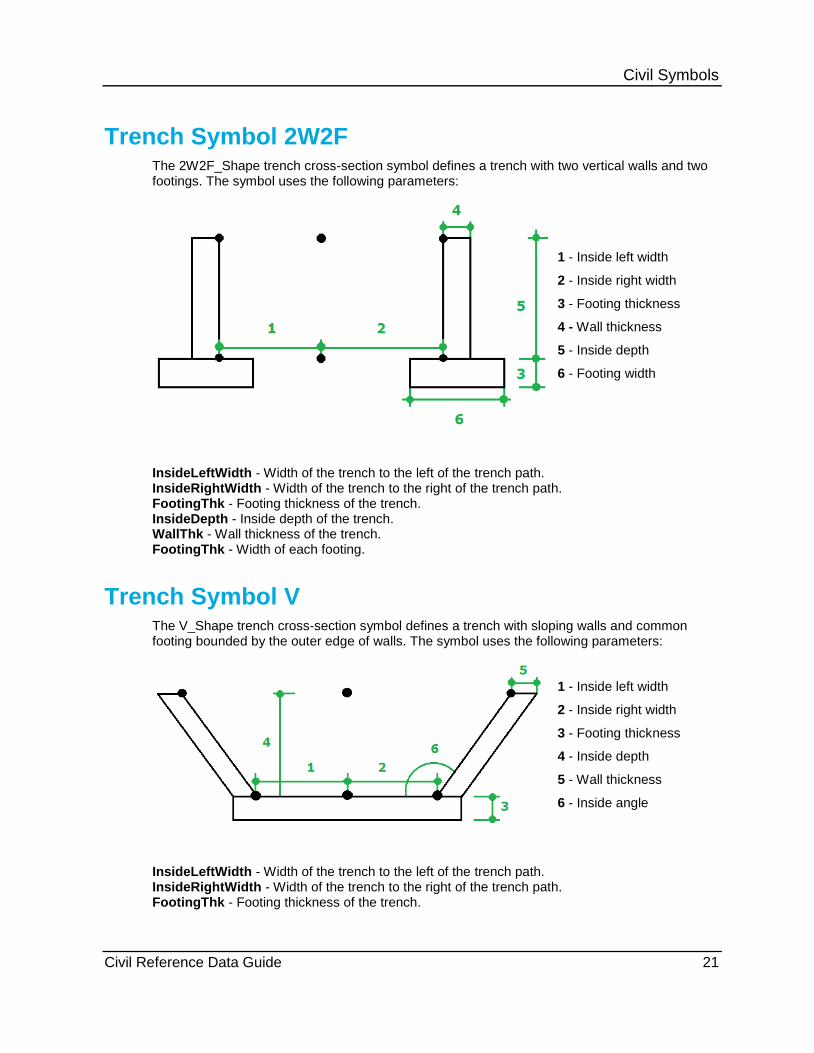
Trench Symbol 2W2F The 2W2F_Shape trench cross-section symbol defines a trench with two vertical walls and two footings. The symbol uses the following parameters:
1 - Inside left width
2 - Inside right width
3 - Footing thickness
4 - Wall thickness
5 - Inside depth
6 - Footing width
InsideLeftWidth - Width of the trench to the left of the trench path. InsideRightWidth - Width of the trench to the right of the trench path. FootingThk - Footing thickness of the trench. InsideDepth - Inside depth of the trench. WallThk - Wall thickness of the trench. FootingThk - Width of each footing.
Trench Symbol V The V_Shape trench cross-section symbol defines a trench with sloping walls and common footing bounded by the outer edge of walls. The symbol uses the following parameters:
1 - Inside left width
2 - Inside right width
3 - Footing thickness
4 - Inside depth
5 - Wall thickness
6 - Inside angle
InsideLeftWidth - Width of the trench to the left of the trench path. InsideRightWidth - Width of the trench to the right of the trench path. FootingThk - Footing thickness of the trench.
Civil Symbols
Civil Reference Data Guide 22
InsideDepth - Inside depth of the trench. WallThk - Wall thickness of the trench. InsideAngle - Slope of the walls with respect to the horizontal line.
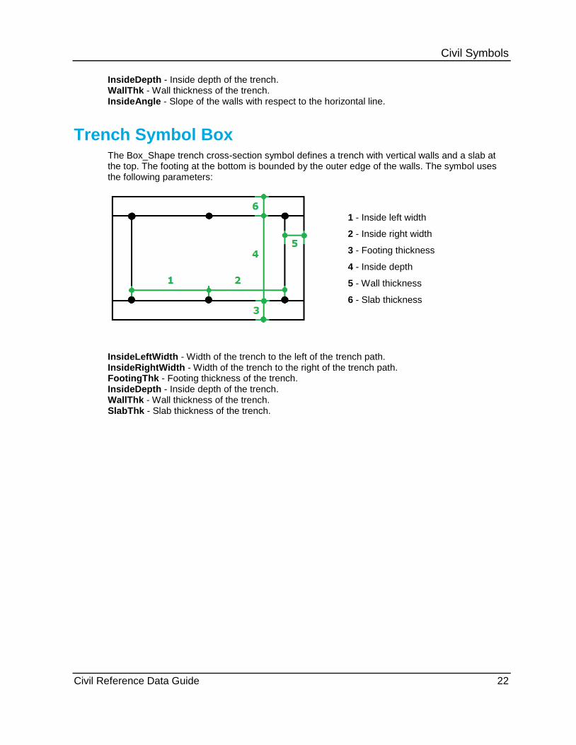
Trench Symbol Box The Box_Shape trench cross-section symbol defines a trench with vertical walls and a slab at the top. The footing at the bottom is bounded by the outer edge of the walls. The symbol uses the following parameters:
1 - Inside left width
2 - Inside right width
3 - Footing thickness
4 - Inside depth
5 - Wall thickness
6 - Slab thickness
InsideLeftWidth - Width of the trench to the left of the trench path. InsideRightWidth - Width of the trench to the right of the trench path. FootingThk - Footing thickness of the trench. InsideDepth - Inside depth of the trench. WallThk - Wall thickness of the trench. SlabThk - Slab thickness of the trench.
Civil Reference Data Guide 23
B Bulkload Files and the Civil Catalog • 8
C Civil Reference Data Overview • 7 Civil Symbols • 14 Code List Workbook • 8 Common Workbook • 8
P Preface • 5
T Trench Composition Worksheet • 10 Trench Cross-Sections Workbook • 8 Trench General Composition Workbook •
10 Trench Symbol 2W1F • 20 Trench Symbol 2W2F • 21 Trench Symbol Box • 22 Trench Symbol U • 20 Trench Symbol V • 21 Trench Turn Part Worksheet • 12 Trench Type Worksheets • 11
W What's New in Civil Reference Data • 6
Index