clearwater spas spa manual - home - landi pools &...
TRANSCRIPT

Clearwater Spas
SPA MANUALResort Series | Beachcraft Series | XS Series
P.O. Box 2140 | Woodinville, WA 98072 | www.clearwaterspas.com
spa manual, US/Canada, 7.5.12 dig
relax | refresh | renew

2
“We reserve the right to improve our product without notice”
Copyright © Clearwater Spas, 2011. All rights reserved. Specifications may change without notice. International products may be configured differently to meet local electrical requirements. [Copyright © trademark 1976 Clearwater Spas™]
relax | refresh | renew

3
TABLE OF CONTENTS
5 INTRODUCTION 5 ICON Key
6 IMPORTANT SAFETY INSTRUCTIONS 6 Read and Follow All Instructions
8 STEPS FOR A SUCCESSFUL INSTALLATION 8 Delivery 9 Site Selection and Preparation 9 Installation – Placing Your Spa 11 Electrical Hook-Up Requirements 13 Filling Your Spa
14 TOPSIDE CONTROL - TURNING ON YOUR SPA 14 Topside Control Button Reference Display, 6-Button 16 Topside Control Button Reference Display, 7 & 8 Button
22 WATER PURITY & FILTRATION 22 Keeping The Water Clean 23 Spa Chemistry 101 25 How To Use the Chemicals 25 Usage Definitions 26 Starting A Chemical Maintenance Program 28 Filtration 29 Ozone Generator 30 Salt System with ISIS Control Panel
32 JETS 32 Types Of Jets 33 Jet, Air and Waterfall Controls 33 Cleaning The Rotating Jets 34 Jet Removal

4
34 MAINTENANCE 34 Spa Light 34 Pillows 34 Spa Skirt 34 The Shell 34 Spa Cover 35 Winterizing 36 Draining The Spa 36 Energy Efficiency Green Technology
38 APPENDIX A 38 Troubleshooting 38 System Trouble 38 Controls 39 Pumps 39 Jets 39 Water 41 FAQ’s - Frequently Asked Questions 43 Warranty

5
INTRODUCTION
Congratulations on your purchase of a new Clearwater spa! Your Clearwater spa is designed and manufactured with the finest components available and is engineered with comfort, low maintenance, and durability in mind.
You will enjoy your spa for several years to come if you are dili-gent with the care and maintenance of your spa. This manual will help you to determine the best way to take care of your spa based on the amount of use and the type of environment your spa is installed.
It is very important for you to read the entire manual before attempting to use your spa. Contained in this manual are im-portant maintenance and start-up procedures as well as safety precautions that must be followed to ensure the prolonged life of your spa and the safety of the people using the spa. Failure to follow start-up procedures may damage your unit and void your warranty.
Please feel free to call your local Clearwater Spas dealer if you have any further questions after reading this manual. We hope you enjoy many years of fun and relaxation in your new Clear-water spa.
ICON Key
The Icon key on the left defines the type of information boxes that will appear throughout the manual. The boxes highlight helpful information that contains useful tips or warnings that apply to the use and care of your spa.
Warning!
Safety Tip
Key Point
ICON KEY

6
Safety Warning!
SAFETY FIRSTIMPORTANT SAFETY INSTRUCTIONS!
READ AND FOLLOW ALL INSTRUCTIONS.SAVE THESE INSTRUCTIONS.
When installing and using this electrical equipment it is recom-mended that a licensed and bonded electrician perform the work. Basic safety precautions should always be followed, including the following:
• A pressure wire connector is provided on the outside of the control box to permit the connection of a solid copper bonding wire between the spa and any metal equipment, metal enclosures of electrical equipment, metal water pipe or conduit within 5 feet of the spa as needed to comply with local requirements.
• A green colored terminal (or a wire connector marked “G”, “GR”, “Ground”, or “Grounding”) is provided. To reduce the risk of electric shock, connect this terminal to the grounding terminal of your electric service or supply panel with a continuous green insulated copper wire equivalent to the circuit conductor supplying this equipment.
• The electrical supply must include a suitably rated Ground Fault Interrupter Circuit to open all underground supply conductors to comply with section 422-20 of the National Electrical Code. ANSI/NFPA 70-1987. The power supply cut off must be readily accessible to the spa occupant, but installed at least 5 feet from spa water.
• Test the performance of the GFCI according to manufac- turers recommendations. If the GFCI does not perform correctly, there may be a ground current flowing indicating the possibility of electric shock. Disconnect the power until the fault has been identified and corrected.
• DANGER –RISK OF ELECTRIC SHOCK. Install at least 5 feet from all metal surfaces.
• DANGER – RISK OF ELECTRIC SHOCK. Do not permit any electric appliance such as a light, telephone, radio or television within 5 feet of a spa or hot tub.
• WARNING –RISK OF CHILD DROWNING. Extreme caution must be exercised to prevent unauthorized access by children. To avoid accidents, ensure that children cannot use a spa or hot tub unless they are supervised at all times.
ElectricalWarning!
ElectricalWarning!

7
• DANGER – To reduce risk of injury, do not remove suction fittings.
• Installation should provide drainage of the electrical equipment area to prevent electrical shortage.
• Store all chemicals in a cool dry area and keep out of children’s reach.
• To reduce the risk of injury: A. Spa heat can cause hyperthermia and unconsciousness! The water in a spa or hot tub should never exceed 104° F (40° C). Water temperatures between 100° F (38° C) and 104° F (40° C) are considered safe for a healthy adult. Lower water tem- peratures are recommended for extended use (exceeding 10 –15 minutes) and for young children.
B. Since excessive water temperatures have a high potential for causing fetal damage during the early months of pregnancy, pregnant or possibly pregnant women should limit water temperatures to 100° F (38° C).
• The use of alcohol, drugs, or medication before or during spa or hot tub use may lead to unconsciousness with the possibility of drowning.
• Persons suffering from obesity or with a medical history of heart disease, low or high blood pressure, circulatory system problems or diabetes should consult a physician before using a spa or hot tub.
• Persons using medication should consult a physician before using a spa or hot tub since some medication may induce drowsiness while other medication may affect heart rate, blood pressure, and circulation.
• Before entering a spa, the user should measure the water temperature since the tolerance of water temperature- regulating devices varies.
WARNINGPREVENT DROWNING 1. SUPERVISE CHILDREN AT ALL TIMES. 2. ATTACH SPA COVER AFTER EACH USE. 3. SPA HEAT CAN CAUSE HYPERTHERMIA AND UNCONSCIOUSNESS. 4. SPA HEAT IN CONJUNCTION WITH ALCOHOL, DRUGS, OR MEDICATION CAN CAUSE UNCONSCIOUSNESS.
PREVENT ELECTROCUTION 1. NEVER PLACE ANY ELECTRIC APPLIANCE WITHIN 5 FEET OF SPA.
NOTE: THIS MARKING IS TO BE REMOVED ONLY BY THE CUSTOMER.
!r
Safety Warning!

8
STEPS FOR A SUCCESSFUL INSTALLATION:
1. PREPARE FOR YOUR DELIVERY Prior to having your new spa delivered to your house, you will need to prepare an area to install the spa. You will need to arrange to have your spa placed in
your desired location and the connection of the elec-trical circuits. In most cities, permits are required for the installation of electrical circuits.
Review the path that your spa will take through your property along with the size of the spa to ensure you have enough clearance. If there are stairs or other obstacles, the spa will have to travel over to get to the site, additional clearances may be required.
We have listed some key points to installing your spa that will help eliminate some of the unforeseeable situations that could occur.
• Avoid installing too close to a building or structure. • Leave enough room around all sides to allow access to service panels. • Install on a load bearing, level platform. • Do not install less than 5 feet from ground conductors. • Use non-conductive conduit for all wiring. • If installing below a deck surface, leave enough room to access and remove service panels.
We recommend a level 4” thick concrete pad if you are installing on land (ver-sus deck or platform). The dimensions of the pad should be at least the out-side dimension of the spa. You should also accomodate for steps or other items around the spa. Allow a few days for curing the cement when calculat-ing your scheduled delivery date.
Balconies and upper decks are not recommended for spa installations, but if you choose to do so, keep in mind that a large filled spa with 6 people can weigh as much as three tons. Balconies and decks must be constructed to current state and local building codes and must support at least 100 pounds per square foot.
If you are building a deck around the spa, be sure that the deck does not cover any of the service panels to the spa. If you are building stairs for getting up to the spa, it is recommended that they be installed in such a way that they can be moved out of the way if entrance to the service panels is required.
The most obvious thing to remember is to plan your installation in a loca-tion where it will be easy to move from the delivery truck to the location site. Spas are typically transported on a mover’s dolly lying on their side. Check for adequate gate clearance and remove any fence panels if necessary to allow access to the installation site.
Importantinstallationhighlights!

9
2. SITE SELECTION AND PREPARATIONThe location of your hot tub is entirely up to you. Carefully read these instructions for various ideas of locations that your new hot tub may be placed.
By the time you have made your spa pur-chase, you probably have a spot already picked out. Prior to the spa delivery, please verify the following:
• Always place the spa on a compacted and level surface. The best surface is a level concrete pad. A spa, full of water, can weigh a great deal. Please ensure the spot can support the weight.• Make sure to level your spa before filling it. • Locate the equipment panel. The system pack, drain valve, owner’s manual and optional ozone generator are usually located all in the same area. Be sure that the connections are tightened during draining. Water inside the system pack will cause the pack to fail and the breaker to trip.• The panels, on all four sides, are removable. Be sure to have access on all four sides.• Be sure to have easy access to the circuit breaker in the sub panel (240 volt models).• Never let water into the sub panel (240 volt models), or into the electrical outlet that your spa is plugged in to. Your 240 volt spa’s sub panel is rain tight when installed correctly with the door closed.
3. INSTALLATION - PLACING YOUR SPAOutdoor and patio installationTo position the spa correctly in your backyard is very important. The reason is your spa’s warranty. The warranty on a spa is voided if the site is not level. If you install your hot tub outdoors, a concrete pad is the best method for a stable and level surface. The concrete pad should be four inches thick. Your spa may be installed on a deck, providing the load rating can handle a full spa with people in it.
Deck installation When placing the spa on a deck, please ensure the maximum load capacity of the deck. Consult a qualified deck builder or structural engineer before you place the hot tub on an elevated deck or indoors. To de-termine the weight of your hot tub, please refer to the specifications on the website.
This weight must not exceed the structural weight of the deck.
Indoor installation When installing a spa indoors, there are some special considerations. The combination of heat and moisture will accumulate on the floor and surround-ing the spa. The flooring material needs to provide a grip when wet. The location also needs proper drainage to prevent water build-up around the

10
spa. When building a room for your spa, it is best to have a floor drain in-stalled. The humidity of a room with a spa can become a problem if there is not enough proper ventilation. Otherwise, problems such as dry rot, mildew or other problems may occur.
Ground preparation Your spa has been engineered to rest on a variety of surfaces. The insulated spa floor base gives you the ability to find the perfect place. A concrete slab is the best for long term. There are other options available as long as the surface is level prior to delivery. The alternatives are 5/8 minus crushed packed rock, or a deck that is rated for the load.
Brick pavers
Cement
Decorative cement, stained
Packed/crushed gravel: 5/8” minus
Stone, slate, granite
Decking: wood, synthetic
Decorative cement & bricks
Marble, travertine
When placing a spa on crushed rock, the easiest way to maintain its form is to build a frame and fill it with the crushed packed rock. Remember, if the spa is placed on grass or dirt, debris will get inside the spa as the users enter and exit.
It is incredibly important to the operation and the draining of the tub for the tub to be level once it is installed. Failure to have the spa level prior to adding water can affect the warranty.

11
4. ELECTRICAL HOOK-UP REQUIREMENTS - 240VRemoving spa panels
1. Remove the plastic ‘tap-cap’ decorative screw head covers from screws on access spa panel.
2. Unscrew the screws from the access spa panel.
3. Remove the spa panel for access to spa com-ponents. Reverse these steps to attach the spa panel.
Electrical connections by licensed personnelTo ensure you will have an opportunity to use your hot tub soon after delivery, it is very important that the required electrical service has been installed.
IMPORTANT: Electrical connections must be made by qualified, licensed personnel. Please contact a licensed residential electri-cian for these services.
All models require a 50 amp single phase, 240 volt circuit breaker in the main electrical service panel. NOTE: WE RECOMMEND THAT A SUB PANEL BE USED TO SUPPLY POWER AND PROTECT THE SPA. All 240 volt Clearwater spas must be wired in accordance with appli-cable local electrical codes, and all electrical work must be done by a licensed electrician. A licensed electrician should install a four-wire electrical service (two line voltages, one neutral, one ground) from the main electrical service panel to the sub-panel, and from the sub-panel to the spa per the appropriate wiring diagram as illustrated below. The grounding conductor must be at least #6 AWG. Your electrician should mount the sub-panel in the vicinity of the spa but it should not be closer than five (5) feet from the spa’s water edge (NEC 680-38 to 41-A-3).
WARNING: Removing or bypassing the GFCI breakers in the sub panel at any time will result in an unsafe spa and will void the warranty.
WIRE SPECIFICATION NOTE: Long electrical runs may require a larger gauge feed wire than stated. We recommend that a maximum voltage drop of 3% be used when calculating the larger wire size.
Refer to the Wiring Diagrams (figure 1-1) for the electrical require-ments of the 240 volt models.
Do not turn on power to the spa when the tub is not filled.
The closer you locate the spa
to the main service panel,
the less money you will have to spend on wire.
Wire can become expensive if you
run long lengths.
Always shut offpower at thesource when
working with anyelectrical power!!Failure to do this
could result inserious injury or
even death!

12
ELECTRICAL REQUIREMENTS - 240V (cont.)
IMPORTANT: Electrical connections must be made by qualified, licensed personnel. Please contact a licensed residential electrician for these services.
Figure 1-1240 volt wiring configuration from the house to the spa

13
FILLING YOUR SPA THROUGH THE FILTER CHAMBERBefore you begin to fill your spa, it is advisable to have your water tested for hardness (water rich in calcium and mineral content). Wells usually contain harder water than urban water supplies. Mineral and metal imbalances in your water can shorten the life of the equip-ment in your spa. Contact your local dealer for proper water analysis.
We recommend that you purchase a high quality “Water Test Kit” for checking pH and sanitizer levels. Test the water daily until your “user load” is determined.
Make sure there is no dirt or sediment at the bottom of the tub and that there is nothing inside the filter compartment before filling with water. Filling the spa through the filter housing will help to prevent air locks (trapped pockets of air) in pumps on start up.
Identify your filter housing and fill as shown:
p TOP-ACCESS DUAL-FILTER HOUSING WITH ANTI-VORTEX SHELTER
p TOP-ACCESS SINGLE-FILTER HOUSING
p FRONT-ACCESS DUAL-FILTER HOUSING
1. Place your garden hose into the filter housing. This will ensure that air bubbles are removed from the lines while you fill the spa.
2. Turn the water on so that most of the water enters through the filter chamber.
3. Fill the water to the proper level – half way up the filter housing, just below the head pillow or just under the neck jets as shown in pictures above.
IMPORTANT!Improperly
balanced water may damage yourspa and void your warranty! Do not fill your tub with water from your
hot water heater!

14
Jets 1
Jets 2 Mode
Light HEATJETS 1 JETS 2
Warm
Cool
Jets 1
Jets 2 Mode
Light HEATJETS 1 JETS 2
Warm
Cool
Figure 16-Button topside control panel
TOPSIDE CONTROL – TURNING ON YOUR SPA
Topside control button reference display Identify your topside 6-button control (See figure 1).
After you identified your topside control system, and the spa is filled, turn your power on and go to your controller spa operations.
Power onIt’s time to turn on the power. Set the breaker at the main service panel to the on position. Now set the breaker at the service panel or spa dis-connect outside the spa to the on position. Then proceed to Initial Start-up referencing your specific control system.
Initial start-upYour spa will enter Priming Mode (‘PR’) when it is energized. During Priming Mode, press “Jets” button(s) repeatedly and be sure all pumps are free of air. Priming Mode lasts less than 5 minutes. Press “Warm” or “Cool” to exit sooner. After Priming Mode, the spa will run in Standard Mode (see Mode section).
Temp control (80°F-104°F/26°C-40°C)The last measured water temperature is constantly displayed. The water tempera-ture displayed is current only when the pump has been running for at least 2 min-utes.
On panels with “Warm” and “Cool” buttons, to display the set temperature, press “Warm” or “Cool” once. To change the set temperature, press a temperature button again before the display stops flashing. Each press of “Warm” or “Cool” will adjust the set temperature. After three seconds, the display will stop flashing and begin to display the current spa temperature.
IMPORTANT!Do not turnpower on untiltub is full ofwater and allvalves are open!
15
Jets 1Press “Jets 1” to turn pump 1 on or off. The device will turn off after 15 minutes.
Jets 2Press the “Jets 2” to turn pump 2 on or off. The device will turn off after 15 minutes.
LightPress “Light” to operate the spa light. Turns off after 4 hours.
ModeMode is changed by pressing “Warm” or “Cool,” then pressing “Mode.” Standard Mode maintains set temperature. ‘STD’ (Std) will be displayed momen-tarily when you switch into Standard Mode. Economy Mode heats the spa to the set temperature only during filter cycles. ‘Ecn’ (Ecn) will display when water temp is not current, and will alternate with water temp when the pump is running.
Sleep Mode heats the spa to within 20°F/10°C of the set temperature only during filter cycles. ‘SLP’ (SLP) will display when water temp is not current, and will alter-nate with water temp when the pump is running.
Preset filter cyclesThe first preset filter cycle begins 6 minutes after the spa is energized. The second preset filter cycle begins 12 hours later. Filter duration is programmable for 2, 4, 6, or 8 hours or for continuous filtration (indicated by ‘F ILC’). The default filter time is 2 hours. To program, press “Warm” or “Cool” then “Jets 1.” Press “Warm” or “Cool” to adjust. Press “Jets 1” to exit programming.
PLEASE NOTE: For circulation systems, the circ pump and the ozone generator (if installed) run 24 hours. In hot environments, the circ pump may turn off if the spa water is 3˚F higher than the set temperature, except during filter cycles. At the beginning of each filter cycle all other equipment will run briefly to purge the plumbing.

16
Cool Warm
Heat
Jets 1 Jets 2 Jets 3 Jets 4 Light Mode
Cool Warm
Heat
Jets 1 Jets 2 Blower/Jets3
Light Mode
Figure 2 | 8-Button (top) and 7-Button (bottom) Topside Controls Note: Your particular topside control will also have branded logo and colored background (not shown in above illustration)
TOPSIDE CONTROL – TURNING ON YOUR SPA
Topside control button reference display Identify your topside 7 and 8 button control (See figure 2).
Initial start-upYour spa will enter Priming Mode (‘PR’) when it is energized. During Priming Mode, press “Jets” button(s) repeatedly and be sure all pumps are free of air. Priming Mode lasts less than 5 minutes. Press “Warm” or “Cool” to exit sooner. After Priming Mode, the spa will run in Standard Mode (see Mode section).
Temp Set (80°F - 104°F / 26.0°C - 40.0°C)The start-up temperature is set at 100°F/37.5°C. The last measured temperature is constantly displayed on the LCD.
Note that the last measured spa temperature displayed is current only when the pump has been running for at least 2 minutes.
Up/DownPress the “Down” or “Up” button once to display the set temperature. Each time ei-ther button is pressed again, the set temperature will increase or decrease depend-ing on which button is pressed. After three seconds, the LCD will automatically display the last measured spa temperature.
ModeThis button is used to switch between standard, economy, and sleep modes. Press “Mode” to enter mode programming, press “Down” to cycle through to desired mode (LCD flashes until confirmed), then press “Mode” to confirm selection.
Standard mode maintains the desired temperature. Note that the last measured spa temperature displayed is current only when the pump as been running for at least 2 minutes. The “STD” will appear on the display momentarily when you switch into Standard Mode.

17
Economy mode heats the spa to the set temperature only during filter cycles. The “Ecn” will appear solid when the temperature is not current and will alternate with the temperature when the temperature is current. Pressing “Jets 1” while in Econ-omy mode puts the spa in Standard-In-Economy mode, (“SE”) which operates the same as Standard Mode, then reverts to Economy Mode automatically after 1 hour. During this time, a press of the “Down” or “Up” followed by “Light” will revert the mode to Economy immediately.
Sleep mode heats the spa to within 20°F (11°C) of the set temperature only during filter cycles. The “Slp” will appear on the display until mode is changed.
Standby modePressing “Down” or “Up” followed by “Jets 2” will turn off all spa functions temporar-ily. This is helpful when changing a filter. The display will read “Sby” (SBY/Standby). Pressing any button exits Standby mode.
Jets 1Press the “Jets 1” button once to turn pump 1 on or off, and to shift between low and high speeds (if equipped). If left running, the low speed turns off after 2 hours and the high speed turns off after 15 minutes.
On non-circ systems, the low speed of pump 1 runs when the blower or any other pump is on. It may also activate for at least 2 minutes every 30 minutes to detect the spa temperature (polling) and then to heat to the set temperature if needed, depending upon mode. When the low speed turns on automatically, it cannot be deactivated from the panel; however, the high speed may be started.
Jets 2Press the “Jets 2” button once to turn pump 2 on or off, and to shift between low and high speeds if it is a two-speed pump. If left running, the pump will turn off after 15 minutes.
Jets 3 / Blower (if equiped)Press the “Jets 3” button once to turn pump 3 (or blower if equiped) on or off. If left running, the pump will turn off after 15 minutes. If applicable.
LightPress the “Light” button to turn the spa light on and off, and to shift between colors. If any light is left on, it will automatically turn off after 4 hours.
Circ Pump (Optional)If your system is equipped with a circ pump, it may be configured to work in one of three different ways:
1) The circ pump operates continuously (24 hours) with the exception of turning off for 30 minutes at a time when the water temperature reaches 3°F (1.5°C) above the set temperature (most likely to happen in very hot climates).
2) The circ pump stays on continuously, regardless of water temperature.

18
3) The circ pump will come on when the system is checking temperature (polling), during filter cycles, during freeze conditions, or when the blower or another pump is on.
Preset Filter CyclesOn all systems, the pump and the ozone generator** will run during filtration. At the start of each filter cycle, the blower will run on highest speed for 30 seconds to clean out the air channels. The lowest speed of pump 2 will run for 5 minutes.
The first filter cycle (“day”) begins 6 minutes after the spa is powered up. The second filter cycle (“night”) begins 12 hours later. Filter duration is program-mable for 1-12 hours (F1-F12). The default filter time is 2 hours. To program, press “Down” or “Up” then “Jets 1”. Press “Down” or “Up” to select the filter dura-tion. Press “Jets 1” to select the number of filter cycles. The display will show “dn” (day cycle only)’ or “n” (“night” cycle only). Press “Down” or “Up” to adjust, then press “Jets 1” to exit the programming mode. For continuousfiltration, use F12 and “dn”.
Clean-up CycleWhen the pump or blower is turned on by a button press, a clean-up cycle begins 30 minutes after the pump or blower is turned off or times out. The pump and the ozone generator** will run for one hour.
**Ozone (optional)The ozone generator (if installed) runs during filter cycles (except when pump 1 is operating at high speed on a non-circ system) and during clean-up cycles.
Freeze ProtectionIf the temperature sensors detect a drop to 44°F (approximately 6.7°C) within the heater, then the pump automatically activates to provide freeze protec-tion. The equipment stays on until 4 minutes after the sensors detect that the spa temperature has risen to 45°F (approximately 7.2°C) or higher. In colder climates, an optional additional freeze sensor may be added to protect against freeze conditions that may not be sensed by the standard sensors. Aux freeze sensor protection acts similarly except with the temperature thresholds de-termined by the switch and without a 4-minute delay in turnoff. See your Clearwater Spas dealer for details.

19
Diagnostic messages
MESSAGE MEANING ACTION REQUIREDNo message on display.Power has been cut off to the spa.
The control panel will be disabled until power returns. Settings are pre-served until the next power-up.
0XX(OHH)
“Overheat” - The spa has shut down. One of the sensors has detected 118°F (approximately 47.8°C) at the heater.
DO NOT ENTER THE WATER. Remove the spa cover and allow water to cool. Once the heater has cooled, reset by pushing any button. If spa does not reset, shut off the power tothe spa and contact your dealer or service organization for assistance.
0XS(OHS)
“Overheat” - The spa has shut down. One of the sensors has detected that the spa water is 110°F (ap-proximately 43.3°C).
DO NOT ENTER THE WATER. Remove the spa cover and allow water to cool. At 107°F (approximately 41.7°C), the spa should automatically reset. If spa does not reset, shut off the power to the spa and contact your dealer or service organization for assistance.
(ICE)
“Ice” - Potential freeze condition detected.
No action required. The pumps will automatically activate regardless of spa status.
SnA(SnA)
Spa is shut down. The sensor that is plugged into the Sensor “A” jack is not working.
If the problem persists, contact your dealer or service organization for as-sistance. (May appear temporarily in an overheat situation and disappear when the heater cools.)
Sn8(SnB)
Spa is shut down. The sensor that is plugged into the Sensor “B” jack is not working.
If the problem persists, contact your dealer or service organization for as-sistance. (May appear temporarily in an overheat situation and disappear when the heater cools.)
SnS(SnS)
Sensors are out of balance. If this is alternating with the temperature, it may just be a temporary condition. If the display shows only this message (periodically blink-ing), the spa is shut down.
If the problem persists, contact your dealer or service organization for as-sistance.
XFL(HFL)
A substantial differencebetween the temperaturesensors was detected.This could indicate a flowproblem.
Check water level in spa. Refill if neces-sary. If the water level is okay make sure the pumps have been primed. If the problem persists, contact your dealer or service organization for assistance.

20
Warning! Shock Hazard! No User Serviceable Parts. Do not attempt service of this control system. Follow all owner’s manual power connection instructions. Installation must be performed by a licensed electrician and all grounding connections must be properly installed. Contact customer service or for assistance.
MESSAGE MEANING ACTION REQUIRED
LF(LF)
Persistent low flow problems. (Displays onthe fifth occurrence of“HFL” message within 24hours.) Heater is shut down, but other spa functions continue to run normally.
Follow action required for “HFL” message. Heating capacity of the spa will not reset automatically; you may press any button to reset. If the problem persists, contact your dealer or service organization for assistance.
dr(dr)
Inadequate water flow detected in the heater (indicates not enough water in the heater).
Check water level in spa. Refill if necessary. If the water level is okay make sure the pumps have been primed. Press any button to reset.
0rY(DrY)
Inadequate water detected in heater. (Displays on thirdoccurrence of “dr” message.) Spa is shut down.
Follow action required for “dr” message. Spa will not automatically reset; you may press any button to reset.
PR(Pr)
When your spa is firstactuated it will go intoPriming mode.
The Priming mode will last for up to 4 minutes and then the spa will begin to heat and maintain the water temperature in the Standard mode.
--Temperature not yet known.
This is normal within the first few minutes of the spa power-up.
STD(Std)
The spa is operating inStandard Mode.
Press “Warm” or “Cool” then press “Mode”
Ecn(Ecn)
The spa is operating inStandard Mode.
Press “Warm” or “Cool” then press “Mode”
SLP(SLP)
Sleep Mode has beenactivated by pressing abutton combination onthe user panel.
Press “Warm” or “Cool” then press “Mode”
21
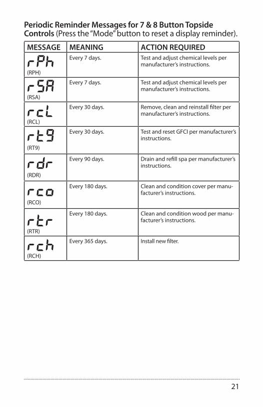
Periodic Reminder Messages for 7 & 8 Button Topside Controls (Press the “Mode” button to reset a display reminder).
MESSAGE MEANING ACTION REQUIRED
rpH(RPH)
Every 7 days. Test and adjust chemical levels per manufacturer’s instructions.
rsa(RSA)
Every 7 days. Test and adjust chemical levels per manufacturer’s instructions.
RCL(RCL)
Every 30 days. Remove, clean and reinstall filter per manufacturer’s instructions.
RT9(RT9)
Every 30 days. Test and reset GFCI per manufacturer’s instructions.
Rdr(RDR)
Every 90 days. Drain and refill spa per manufacturer’s instructions.
RCO(RCO)
Every 180 days. Clean and condition cover per manu-facturer’s instructions.
rtr(RTR)
Every 180 days. Clean and condition wood per manu-facturer’s instructions.
rcH(RCH)
Every 365 days. Install new filter.

22
WATER PURITY & FILTRATION
Keeping the water clean – chemical sanitizers
One of the bigger reasons that people require service on their spa is because they haven’t followed a chemical application regiment. Water can accumulate impuri-ties that can worsen the performance or even damage the filtration system if chemicals are not applied on a regular basis. The water can even become unhealthy if chemicals are not used to sanitize the water. Improper pH levels or calcium levels can cause either corrosion of parts or scale build-up.
We recommend that you begin a routine of applying chemicals that you can get comfortable with and follow all the time. If you get into a scheduled regiment, it will be easier to remember when to apply the chemicals.
Your spa comes with an ozonator that will do a very good job at kill-ing bacteria and oxygenating the water, but chlorine or bromine are used to compliment the job of the ozonator.
Finally, the best way to keep the water clean over long periods of time is to change the water four times a year. Connect a hose to the drain valve and open it all the way to allow the tub to drain all the way. Use a shop-vac to remove any standing water and debris at the bottom of the tub. Refer to the maintenance section for instructions on cleaning the tub before refilling it.
IMPORTANT!Always read
directions onchemical container
thoroughlybefore
using spa chemicals.

23
Spa Chemistry 101At first, trying to understand spa chemistry can seem like a daunt-ing task to say the least. We intend on helping you understand spa chemicals so that you can maintain the health of your spa at the best level possible.
There are three basic principals to spa water chemistry.
1. Sanitize/Disinfect (kill viruses, germs, etc.) 2. Oxidize (break down organic compounds like oils and sweat) 3. Maintain slightly base (alkaline) water (pH of 7.4 - 7.6). This controls the corrosiveness of the water, prevents excessive scaling (mineral formation on surfaces exposed to water, and insures that the water is comfortable to the skin.
Once you have a good understanding of the chemicals that are used in your spa, you will be able to maintain proper water balance. Water balance is reached when all elements (pH, total alkalinity, calcium hardness and total dis-solved solids) are within their proper ranges.
The following definitions for chemicals will help you understand what the chemical is and what it is used for:
Sanitizers
CHLORINE - Chlorine is widely used as a sanitizer or disinfectant in pool and spa water to kill bacteria, viruses and algae, and oxidizes ammonia and nitrogen com-pounds such as swimmer waste. Its formal name is Sodium Dichlor and is referred to as a chlorinated concentrate. Sodium Dichlor is a fast-dissolving, granular, stabi-lized organic chlorine compound providing either 56% or 63% available chlorine. Cyanuric acid and/or stabilizers are added to prevent U.V. light destruction of the chlo-rine by the sun.
Chlorinated concentrate produces chlorides and chloramines, which are formed when chlorine has combined with ammonia and nitrogen in pool and spa water. Chloramines exude a foul, “chlorine” odor and causes skin and eye irritation.
BROMINE – Bromine is the other commonly used sanitizer or disinfectant in pool and spa water to kill bacteria and algae, and oxidizes ammonia and nitrogen com-pounds such as swimmer waste. This chemical does not eliminate swimmer waste unless it is combined with an oxidizer (non-chlorine shock). It is very susceptible to direct sunlight, therefore is not efficient in outdoor pools. Bromine is sometimes used as an alternative for people whom are allergic or sensitive to chlorine products.
Bromine products are available as sodium bromide and bromine tablets. The bro-mide ion has no effective disinfectant or sanitizing capabilities without the use of nonchlorine shock (potassium monopersulfate). Potassium monopersulfate is added to oxidize, or activate, bromide ion to bromine, which rapidly forms the ac-tive sanitizer - hypobromous acid - in spa water. Upon reaction with bacteria and other spa contaminants, hypobromous acid is reduced back to bromide ion, ready to be activated again by the next dose of potassium monopersulfate. Potassium monopersulfate begins to produce bromine immediately and continues to do so
The pH scale goes from
0 to 14, with zero beingextremely
acidic and 14 being extremely base (alkaline).
Seven isconsidered neutral pH.

24
for several hours, providing sufficient time for oxidation of bather waste and other organic contamination such as ammonia and nitrogen.
NON-CHLORINE SHOCK (Potassium Monopersulfate) – Also knownas “Oxy-Shock”, is an important chemical used in the process of disinfecting and sanitizing the spa water. Non-chlorine shock is used as an oxidation agent to oxi-dize and eliminate organic contaminants, dead algae and debris, and will also con-vert the chlorine by-products (chlorides and chloramines) back into free available chlorine.
When used with bromine products, non-chlorine shock is used with sodium bro-mide in a two-part disinfection system. Potassium monopersulfate (non- chlorine shock) is added to oxidize, or activate, bromide ion to bromine which rapidly forms the active sanitizer - hypobromous acid - in spa water. Upon reaction with bacteria and other spa contaminants, hypobromous acid is reduced back to bromide ion, ready to be activated again by the next dose of potassium monopersulfate.Most non-chlorine shock products have buffers that reduce pH instability, and cor-rosion inhibitors that help protect the heater and other metal surfaces.
OZONE – Ozone is a powerful gas that is used as a sanitizer and an oxidant to keep the spa water clean and disinfected. Although ozone is about 3000 times more powerful than chlorine, it has a tendency to dissipate quickly and does not create any sanitizer residual. By using an ozonator for your spa, you can cut maintenance time and chemical costs by as much as 60%. Ozone is manufactured by an ozona-tor (ozone generator) and is dispensed during the filtration mode.
pH Controllers
SODIUM BICARBONATE - Commonly used to increase pH and total alkalinity of spa water. Sodium bicarbonate is also known as natural baking soda.
SODIUM CARBONATE – Also known as soda ash, is a substance used to raise pH and total alkalinity.
SODIUM BISULFATE – Also known as dry acid, the chemical used to lower pH and total alkalinity of spa water.
MURIATIC ACID – A liquid acid that is most commonly used to reduce pH and total alkalinity levels. It tends to be very strong and is not recommended for use in spas.
Water Conditioners
FLOCCULENT – A compound which clarifies spa water by gathering oils, dirt, scum, metal deposits and small contaminant particles into larger globules, which then can be easily trapped in the filtering system allowing the filtering system to work more effectively.
CLARIFIER – A compound used to remove dissolved solids, metals, dirt, oils, or other contaminants from spa and pool water.
SCUM BALL™ – A softball sized ball that is kept in the water. The ball is chemically

25
treated so that it attracts contaminants that would normally be trapped in the filter.
SEQUESTERING AGENT – Stain & scale preventing compounds that sequester dis-solved metals to prevent water discoloration.
CALCIUM CHLORIDE – A soluble white compound used to raise the calcium hard-ness of spa & pool water, to protect equipment from corrosion.
ALGAECIDE – A chemical used to kill algae and prevent it from growing back.
DEFOAMER – A compound used to reduce or eliminate foaming in spa water. Products containing Chitin do this naturally.
CHITIN – A naturally occurring polymer (pronounced KY-tin) found in crab and lobster shells. As a spa clarifier, it is the best flocculating agent available. Removes oils, dirt, scum, and metal deposits and allows the filtering system to work more effectively.
How To Use The ChemicalsNow that you have some knowledge about spa chemicals, you will learn how to use those chemicals to maintain balanced water in your spa. This section will ex-plain how to apply chemicals, how much to use, and when to use them.
Usage DefinitionsBefore getting into how much and when, it is important to understand some of the terminology that is used to describe how the chemicals are applied:
P.P.M. – Parts Per Million. Expressed as a ratio of number out of 1 million.
SHOCK – Addition of an oxidizer (OXY SHOCK) or superchlorinator to the water to break-down the organic contaminates on which bacteria feed and to destroy am-monia and nitrogen compounds (oxidize only).
SUPERCHLORINATION – Means the addition of enough chlorine in the water to kill all living things (sanitize) and destroy any organic wastes present in the water (oxidize). Usually this means about double your normal dose of chlorine. Super-chlorination can be done once a day for heavy bather loads or as infrequent as once a week for a moderately used spa.
CHLORINATION – To add chlorine to your spa on a regular basis to disinfect and oxidize your spa water.
BREAK POINT CHLORINATION – The process of shocking the water with signifi-cant quantities of chlorine to oxidize all contaminants and organic wastes and leave all remaining chlorine as free chlorine.
CALCIUM HARDNESS – A measure of the amount of calcium dissolved in water. Water with low hardness can lead to corrosion of metal parts. Water with high level of hardness can cause scale (calcium crust) build up on spa surfaces and clog filters, heaters and pumps.
WATER BALANCE – Water balance is reached when all elements (pH, total alkalinity,

26
calcium hardness and total dissolved solids) are within their proper ranges.
ENZYMES – Biodegradable proteins which breakdown oils, films and digest scum in spa water.
FREE CHLORINE – The amount of chlorine available to kill bacteria or algae. Also known as “Available Chlorine”.
COMBINED CHLORINE – The portion of the total chlorine in water in chemical combination with ammonia, organics, and nitrogen, most of which are chlora-mines.
TOTAL ALKALINITY (TA) – The measure in PPM of all the dissolvedbase/alkaline material in the water. The acid-neutralizing capacity of water which indicates its buffering ability, or resistance to fluctuations in pH.
TOTAL DISSOLVED SOLIDS (TDS) – The total amount of dissolved materials in pool or spa water. The ideal range is from 1,000 to 2,000 ppm in pools and 1,500 ppm above the start-up TDS in spas.
Starting A Chemical Maintenance ProgramUltimately, in a chemical maintenance program, the goal is to maintain water balance. If you apply chemicals and test your water on a regular basis, water balance is easy to maintain and your spa water will stay clear and healthy. Although test strips are fairly accurate, test kits are also available that are very accurate and will test every-thing that you will need to monitor your water chemistry.
Three main parameters should be tracked closely:
1. pH 2. Free chlorine 3. Alkalinity
T.D.S. (Total Dissolved Solids) and calcium hardness should be checked after the first three are in the correct range. Test strips and test kits come with in-structions on how to diagnose readings to determine whether the chemicals are in the right range. Table 2-1 shows how to dispense chemicals and how often to do it.
In the beginning, it is a good idea to test your water daily to learn how the water changes with the addition of chemicals. By keeping a log, you will be able to keep better track of your water condition.
When adding water to your spa for the first time or changing the water, you should superchlorinate the water by doubling (1 tbsp. Per 100 gallons) the regular dose of chlorine. It is a good idea to wait for 8 hours before entering your spa after superchlorinating the water.
Remember that keeping your spa water healthy keeps you, your family, and your
WATER BALANCE is reached when all elements (free chlorine, pH, totalalkalinity, calcium hardness and totaldissolved solids) are within theirproper ranges.

27
guests healthy too. Most service calls for spa repairs are related to problems caused by not maintaining balanced spa water.
Figure 2-1: Spa water care

28
Filtration Your spa is pre-programmed to run a 2-hour filter cycle twice a day.For the system to work properly, the filters must be hosed off at least once a week and thoroughly cleaned once a month with a filter de-greaser. We recommend that you buy an extra filter cartridge from your Clearwater Spas dealer to alternate with the filters included with your spa. A dirty filter will restrict water flow and will prohibit the filtering system from keeping your spa clean. If the filters are not cleaned for extended periods, it could possibly damage the pumps.
If you have a problem with floating contaminants, you may want to purchase a skimmer net to easily remove bugs, leaves, etc…
Details on cleaning the filters are included in the maintenance section, but as a reminder, it is important to first turn off the power to the spa. Leaving the power on while changing the filters could allow objects to be drawn into the heater and/or pump and may damage your equipment.
To remove filters, DOUBLE CARTRIDGE - TOP LOADING (75 sq/ft per filter):
To remove filter, SINGLE CARTRIDGE - TOP LOADING (50 sq/ft filter):
Ask your Clearwater Spas dealer for more information on the new Microban Filters, a new technology with antimicrobial protection that will inhibit the growth of bacteria and mold.
CAUTION!Turn off the power to the spa before removing the filter!
For the bestperformancepossible, clean the filter weekly.
Remove cap from weir. Locate filter basket clips. Remove filter basket clips. Remove filter basket.
Locate top of filter. Insert two or three fingers into filter and pull out.
Clean or replace filter.
Turn filter housing counter-clockwise to remove.
Lift and remove filter basket.
Insert two or three fingers into filter and pull out.
Clean or replace filter.

29
To remove filters, DOUBLE CARTRIDGE - FRONT LOADING (50 sq/ft per filter):
Slide door face upwards. Remove door face. Pull out leaf basket. Gently unscrew and remove both filters.
Clean or replace filters. Note: be sure not to overtighten filters when replacing.
Ozone Generator
The spa manufacturing company offers an optional Ozonator made to our specifi-cations. Ozonators supply the spa water with ozone, which is an extremely effec-tive oxidant that will kill bacteria and microorganisms. The Ozonator will distribute ozone into your spa automatically during the filter cycles and will keep your spa and water sparkling clean. Even though ozone is effective at keeping your water clean, it cannot replace the use of chlorine or bromine. Refer to the chemical sec-tion for more information.
No maintenance is necessary on the ozonator. The ozonator works during the filter cycles set by the controller only. If your spa did not include an optional ozonator and you would like to have one installed, contact your spa dealer.

30
Salt System with ISIS control panel.
EASY START UP DIRECTIONS:NOTE: Any time you add a chemical, turn the jets on to help dissolve it appropriately.
Step 1) Fill your spa using the “Pre-filter” provided in your start up kit (helps start with pure water).Step 2) Flip breaker on. Wait until water temperature reaches at least 80 degrees.Step 3) Make sure the Genesis button is OFF.Step 4) Balance calcium hardness from 100 to 150 ppm and wait. Note: for well water, use ‘metal gone’ as instructed.Step 5) Balance alkalinity first. Wait 2 hours. Once the alkalinity is balanced adjust PH up or down as needed.Step 6) Shock the water with 1 or 2 tbs. of shock (also provided in the start up kit).Step 7) Put 1 bottle/ 175 gallons of Tru-Blu (sodium bromide/ salt) in the water (*see letter “A”).Step 8) After 30 minutes, when the sodium has had a chance to dissolve, turn the Genesis control button up to #5 for larger spas and #3 for smaller spas. Step 9) Once the standard test strip begins to show a very light green color ‘1’ for Bromine (sanitizer), turn the button down to #3 or #2 (depending on the size of your spa) and adjust the button according to how much usage your spa receives and what your test strips indicate. With higher usage, turn the button up. With less usage, turn the button down.
The control of the ISIS Top Side is identical to the ISIS 1 controller. The userinter-face is as follows:• To activate the topside control, any of the push button keys must be held down for the entire Key Lockout deactivation sequence which takes several seconds.• If the Key Lockout has been activated and any push button key is pressed, the three digit Seven Segment Display will display “Loc”.• After one second, the three digit Seven Segment Display will display a “3” in the center digit.• The push button key must be held down until the three digit Seven Segment Display decreases to “1” and the power setting is displayed, then bromine output or boost can be adjusted.• The displayed count will be displayed as quickly as in 0.75 second intervals. If the depressed push button key is not released within five seconds after the power setting is displayed, the Key Lockout will be reactivated preventing an accidental increase or decrease in bromine production ( this is a precautionary – safety feature of the ISIS TS System).• After the power setting is displayed, the push button keys are activated and power setting is enabled (normal error code display is also resumed). If any key remains depressed for five seconds during the deactivated Key Lockout period,

31
the Key Lockout will reactivate and disable control features.• The Key Lockout will reactivate in 20 seconds after the last operational release of a push button key. The three digit Seven Segment Display will display “Loc” for 0.5 seconds when Key Lockout is reactivated.• Upon reactivation of the Key Lockout, the Topside Control Seven Segment Display will display the power setting along with any active error codes or power setting LED displays. If the Electrode Current display feature is enabled, the Key Lockout will not reactivate.
It may take a few hours up to a day to reach the desired level of Bromine (sani-tizer). The correct level of Bromine with the Genesis System should be between 0-1 on the generic bromine test strip. The strips that test for the active bromine (sanitizer) level are designed for generic bromine systems. Specifically for Gen-esis, if the bromine level reads 2 or more (which reads ok on the test strip) then there is actually too much pure bromine in your spa. For the Genesis system that produces a more “pure” sanitizer (without any “fillers” or extra chemicals), the “OK” range for the bromine will read between 0-1 (light green) on a common bromine test strip.
Between 0-1 on the test strip is where you want your Bromine (sanitizer) level to remain. For continued water care, adjust the Genesis control dial as needed to remain in the “true” ok range (0-1) and “balance” your water regularly. Continue to test the water at least once weekly to monitor the water quality. If you do not use your spa for an extended period of time, set the Genesis control dial back down to a setting of #3 or #2 (depending on the size of your spa) to have the spa continue sanitizing when you are not home. For higher spa usage, occasional shocking may be required. Any time shock is used, the lid must remain open and people should wait to use the spa for 1 hour.
*A: Periodically (every few months) check the Sodium Bromide (sanitizer) level by using the Genesis (or equivalent) test strip. The reading on the test should be 1200-1800 parts per million. If the salt level is too high, in the window of the Genesis control panel will flash and the system will not operate properly. If the salt level is too low it will not be able to produce bromine properly. Keeping the sodium bromide in the correct level will ensure the Genesis system has the proper level to operate at its optimum efficiency.
Suggestions: You may wish to use a high quality natural enzyme clarifier (SeaK-lear or GLB is recommended) or a similar product to help keep the filters clean and assist in controlling water line build up. If you have a pump that filters twice a day, or have any further questions, please contact your salesperson for further instructions.

32
JETS
Types of JetsYour Clearwater spa comes with different types of jets and jet configurations. Each type of jet has a specific purpose and operates differently than the others. All jets with the exception of the fixed jets in the foot well by the light are adjustable and can be turned on or off. They all combine to create a luxurious and invigorating hydro-therapy environment that can’t be beat.
Most of the jets are removable for easy cleaning. It is not uncommon for particulates to get caught in the jets causing them to stop rotating, especially in environments where there are trees overhead or nearby. Refer to the next section for jet cleaning instructions. Most of the jets are easiest to adjust or remove when the pumps are off.
NOTE: Jet styles may change from time to time such as the cosmetic outer ring or inside nozzle. All of these jet styles offer similar water flow move-ment, directional adjustments and/or spinning motions.
Micro Power Flow Massage Jet: 2”This jet allows the spa manufacturer to group multiple jets together in a small area. These jet groupings allow the hydrotherapy to be maximized in leg, arm and shoulder areas for your ultimate comfort.
Directional, Spinner Power Flow Massage Jet: 2” | 3” | 3.5” | 5” This jet provides massaging relief to the areas affected by discomfort from carpel tunnel syndrome and arthritis. This jet can be directed to maximize your ultimate comfort, as it is fully adjustable.
Directional Maximum Power Flow Massage Jet: 3” | 3.5” | 5”This jet allows for maximum water flow volume that can be adjusted directionally for a deep tissue massage.
Multi-Port Spinning Power Flow Massage Jet: 3” | 3.5” | 5” This jet propels an extravagant swirl of water and air bubbles. With just a touch, you can change this directional jet to a rotating jet. Its mult-port massage action creates a luxurious hydrotherapy experience.

33
Jet, air and waterfall controlsDiverter ValvesThis valve, which is located at water line, is used to divert the power from the pump to one of the “Hot Seats” or the other. The valve has a 180° range from one side to the other. By moving the valve to one side, the pump will deliver all of its power to one seat. Moving the valve to the other side will shift the power to the other seat. If the valve is moved to a posi-tion anywhere between both sides, the power will be shared between both sides. The other diverter valve controls the power going to “Ex-treme Power Flo Jet” (foot well jet).
Waterfall Control and Waterfall JetSoothing waterfalls, water fans or waterfall arches are featured on selected models. Handy turn knob controls allows for complete adjustability of flow to match your every mood.
Air ControlsThese valves, which are located on the topside, are used to control the air that flows through the jets. By introducing air into the jets, they ef-fectively double their power. Because there are so many tub models, it would be impractical to
describe which air controls correspond with what jets. Experiment by opening all the jets and turn on one motor at a time. Turn the air controls one at a time and take note as to what jets are affected. Air controls will only affect the jets that are operating.
Cleaning The Rotating JetsOccasionally debris will get caught in the housing of the rotating jets causing the jet to either slow down the rotation or stop rotating altogether. This can easily be fixed by removing the jet and cleaning it. Always turn pumps off before removing jets. After removing the jet, they can easily be cleaned by vigorously shaking the jet while in the water. If the jet nozzle does not spin freely after doing this, move the nozzle to the outside rotating position and turn the nozzle in the rotating pat-tern until it starts to bind. Move the nozzle back and forth over the binding spot until it starts to free up. Shake the jet in the water again and check for free rotation.

34
Jet RemovalTo remove jets simply turn the outside ring of the jet coun-terclockwise approximately one quarter turn and pull jet out (Figure 3-1). To replace the jet, simply place the jet in the shell and turn the jet until the slots line up, then turn jet one quarter turn clockwise until secured. The jet will easily push into place and “snap” when it is locked.
MAINTENANCE
PillowsYour spa is equipped with high quality polyurethane foam pillows. These pillows can be removed by simply pulling them off. To replace them, line the receptacle holes up with the buttons on the spa.
Cedar Wood Spa Cabinetry – Natural lasting beautyThe spa manufacturing company uses select clear cedar for manufacturing the ex-terior cabinet. High quality wood is used for beauty and functionality. A generous coat of water base sealer has been applied at the factory. To maintain the beauti-ful appearance and extend the life of the cabinet, apply a coat of water base clear sealer once a year.
Synthetic RIM Spa Cabinetry – Low maintenance durabilityThis award winning cabinet system offers the beautiful look of tongue and groove wood cabinetry with the highest impact resistance of any cabinet system in the spa industry to date! The RIM cabinet is designed to withstand impacts, heat, cold and rain while retaining the long lasting look of elegance.
If access to the plumbing, motors or the controller is required, remove the screws on the service panels using the square bit supplied with the spa. Panels can then be easily removed by pulling the panel away from the spa.
WARNING!Do not sand quaritefinishes.
The ShellYour spa is constructed with a high quality, impact resistant, thermoplas-tic shell that requires very little maintenance. Make sure that when you drain and clean your spa that you use a mild, nonabrasive cleaner and cleaning pads. We recommend that you use a cleaner made specifically for cleaning spas. They tend to be non-abrasive and easy to rinse off com-pletely. Contact your spa dealer for information on waxes and sealers.
Spa CoverIf you purchased a cover with your spa, you will want to be sure to keep it clean and protected. Spa covers exposed to the outdoors take a beating from the ele-ments. Use a vinyl protectant to discourage deterioration caused by the UV rays from the sun. This will also minimize rain penetration. See your spa dealer for a vinyl protectant.
Once a month, take the cover off the spa and use a sponge and dish soap to scrub the cover clean. Keeping the cover free of dirt and debris is the most important maintenance task for the cover. Be sure to clean the seams extra well.

35
Your cover comes with screws that are used to fasten the receiving end of the strap locks. Simply align the cover on the spa and stretch out the straps until they are tight. Mark the location of the strap receptacles, then fasten them to the spa skirt with the screws supplied.
WinterizingSince ‘freeze damage’ is not covered under the Limited Warranty, we recom-mend contacting and having a spa professional prepare your spa for winterizing protection. If you live in a climate where winter temperatures are below freezing and power to the spa will be disconnected, follow these procedures for draining:
Winterizing guidelines:1. Add an algaecide to the water and run pumps for half an hour to evenly disperse algaecide.
2. Turn off power to the unit at the circuit breaker.
3. Drain the spa by attaching a garden hose to the open the drain valve. After the spa is empty, remove the hose and leave the drain valve open.
4. For freeze protection – Access motor area by removing the outer front panels to the right and left of the controller panel and unscrew the plumbing collars from the pumps. Leave union couplings disconnected. Vacuum out lines with a wet/dry shop vacuum.
5. Soak up any excess water that drains from motors and associated plumbing with a towel. Keep water and debris out by covering with a rigid spa cover.
6. Before using the spa again, reattach pump couplings, close drain valve, and review startup instructions.
If the spa is to be used during the winter, save energy by turning the temperature down and keeping the spa covered. If the spa reaches freezing temperatures, the main pumps will automatically turn on to circulate the water.

36
Draining The Spa
We recommend that you drain and clean your spa no less than 3 or 4 times per year, depending on how frequently you use it and how well you main-tain your water. In most cases this simple process will only take about an hour to accomplish.
Drain Location: The drain is located in the center of the Dura Floor directly under the topside control panel. This is the innermost closed position.
Step 1: Remove CapUsing your hand, unscrew thecap to the drain.
Step 2: Attach HoseScrew on a garden hose. Place the other end of the hose in the area you want the water to drain to.
Step 3: Open DrainWith the hose attached, turnthe round portion of the draincounterclockwise until it stops,then gently pull the round portion(with hose attached) out untilyou hear a click (approx 1/4”).
Step 4: Close Drain When you are done draining your spa, reverse these steps to close the drain (step 3), remove the hose (step 2), screw on the cap (step 1).
Detail of drain

37
ENERGY EFFICIENCY GREEN TECHNOLOGY
Providing a greener spa.
Your spa manufacturer is strongly committed to protect-ing the health of our environment and manufacturing energy efficient hot tubs that help to conserve our natural resources. We strive to provide clean air, clean water and recycling solutions – both in how we build our product and in our product itself.
technology
E-Smart Technology | Eco Effect Technology
Your spa is made with ‘e-smart or eco-effect technology’ built into every hot tub to provide a complete energy efficient system. From the initial engineering design stage through our manufacturing, recycling and product usage, we have set a high standard to keep our hot tubs environmentally sound.
Clean Air Factory
Our Eco-Spray™ process for strengthing every spa shell has 0% styrene, no odor and emits no VOC’s (volitile organic compounds) for a clean air enironment.
Recycling.
Your spa manufacturer takes pride in using 100% recycled ABS to fabri-cate the insulated floor systems for spas equipped with this feature. They also recycle 100% of their wood, plastic and cardboard waste.

38
APPENDIX A
TroubleshootingFor error message on your topside control, see control reference from the Initial Start-up.
PROBLEM PROBABLE CAUSE REMEDYGFCI trips (on startup) Improper or defective
wiring.Electrician should inspect forwiring mistakes.
GFCI trips A) Ozone generator defective.
Unplug from controller andreset breaker to verify problem.
B) Unknown cause. Unplug all components, thenplug in one at a time until problem is identified.
C) Heater element burned out.
Contact customer service.
System not operating A) System lockup. Reset power source or GFCI.
B) Improper or defective wiring.
Electrician should inspect forwiring mistakes.
C) House circuit breaker tripped to off position.
Reset circuit breaker.
GFCI tripped to off position. Reset GFCI. If still tripping,Check installation guide forproper wiring.
ControlsPROBLEM PROBABLE CAUSE REMEDY
System overheating, shutdown
A) Restricted filter. Clean filter overnight with filter degreaser.
B) Water too low. Fill water to fill line on filter door.
Control response poor
A) Low water level. Fill water to fill line on filter door.
B) Dirty filter. Clean filter overnight with filter degreaser.
C) Closed slice valves. Remove service panels and open slice valves.
Water won’t heat A) Same suggestions as system overheating and poor control response.
If problem persists, contact customer service.
B) Improper or defective wiring.
Electrician should inspect for wiring mistakes.

39
Pumps
PROBLEM PROBABLE CAUSE REMEDYNoisy pump or motor A) Clogged filter or pump
inlets.Clean filter, filter basket and pump inlets
B) Low water level. Fill water to fill line on filter door.
C) Slice valves not open. Remove service panels and open slice valves.
D) Debris in pump(s). Contact customer service.
E) Damaged or worn motor bearings.
Contact customer service.
Motor not functioning A) Cord unplugged or damaged.
Check wiring to controller. Contact customer service.
B) Motor overloaded. Let motor cool for one hour, open all jets. Motor will reset automatically.
C) Defective start switch. Contact customer service.
D) Blockage in line. Contact customer service.
E) Kink in hose. Remove service panels and check for a kinked hose.
F) Slice valves not open. Remove service panels and open slice valves.
G) Blown fuse. Check fuses. Replace if bad.
JetsPROBLEM PROBABLE CAUSE REMEDY
Rotating jets won’t rotate
Debris in jet housing. See ‘Cleaning the rotating jets’ section of the JETS chapter.
WaterPROBLEM PROBABLE CAUSE REMEDY
Water leak A) Compression fittings (unions) have loosened.
Tighten fittings.
B) Leak at barbed fitting. Cut off hose clamp through the raised ear portion and reseat hose. Reconnect with a new hose clamp or a ‘worm drive clamp’.

40
Water (Continued)PROBLEM PROBABLE CAUSE REMEDY
Cloudy water A) Clogged or blocked filter fitting.
Remove filter and clean fitting.
B) Dirty filter. Clean filter.
C) Poor water chemistry. Balance water.
D) Insufficient filter time. Increase filter time to a mini-mum 4 hours per filter cycle.
E) Particles too small for filter.
Add flocculent and clarifier.
F) High pH and / or alkalinity.
Adjust pH with pH Down.
G) Trace metals in water. Use metal remover.
H) Too much clarifier used. Wait to be filtered out.
Green water A) Algae. Add algaecide, superchlorinate and add Oxy Shock. Check ozonator.
B) Metal corrosion in equipment.
PH too low, adjust to 7.2 to 7.6 with pH Up.
Brown water Iron present in water. Superchlorinate and add Oxy Shock. Add metal remover.
Blue-green water Copper present in water. Usually only found in spas with gas heaters.
PH too low, adjust to 7.2 to 7.6 with pH Up.
Bleached hair/bathing suits. Eye irritation.
Too much chlorine. Allow to dissipate. Add Oxy Shock.
Bad smell, eye & skin irritation, complaints of too much chlorine.
Too much chloramines, not enough free chlorine in water.
Superchlorinate and maintain 3 - 5 PPM. Add Oxy Shock.
Scale formation on walls and equipment.
A) High pH. Reduce to 7.2 to 7.6 pH.
B) Calcium too high. Drain 20% to 40% of tub and refill with “soft” water. Maintain at 150 to 400 PPM.
pH fluctuates radically Total alkalinity out of balance.
Balance alkalinity.

41
Frequently asked questions
Q: Why is my spa not heating?A: Check which mode you are in: standard, sleep or economy. See ‘Topside Control’ . Standard and Economy mode will allow temperature to drop 10 degrees. Sleep mode will allow temperature to drop 20 degrees.
Q: The system is receiving proper voltage, why doesn’t anything function?A: 1. Check for blown fuses, burn marks or signs of tampering in the box. 2. Power down the spa, and reset the GFCI. If problem persists, contact customer service for tech support.
Q: What does the ozone generator do?A: An ozonator purifies naturally. It produces an active oxygen that attacks bacteria at microscopic levels reducing the amount of chemicals needed for perfect water. Ozone is also useful in coagulation of metals an other contaminants found in some areas.
Q: How do I know if my ozonator is working?A: During a filter cycle, a green LED light on the ozonator will light and bubbles will move through the clear water line that connects to the ozonator.
Q: How do I fill the spa with water?A: 1. Place your garden hose into the filter housing. This will ensure that air bubbles are removed from the lines while you fill the spa. 2. Turn the water on so that most of the water enters through the filter chamber. 3. Fill the water to the proper level – half way up the filter housing.
Q: How do I drain the spa?A: See instructions ‘Draining The Spa’. > Drain Location: The drain is located in the center of the floor directly under the topside control panel. This is the innermost closed position. 1. Remove Cap. Using your hand, unscrew the cap to the drain. 2. Attach Hose. Screw on a garden hose. Place the other end of the hose in the area you want the water to drain to. 3. Open Drain. With the hose attached, turn the round portion of the drain counterclockwise until it stops, then gently pull the round portion (with hose attached) out until you hear a click (approx 1/4”). 4. Close Drain. When you are done draining your spa, reverse these steps to close the drain (step 3), remove the hose (step 2), screw on the cap (step 1).

42
NOTES

43
Limited WarrantyEvery Clearwater Spa is manufactured to our exacting standards and requirements, and your long-term enjoyment of your spa is our ultimate goal. Therefore, we are proud to provide these comprehensive warranties with our products.
HOW THE WARRANTY WORKSIn the event of a covered defect under this Limited Warranty, Clearwater Spas or its agent will make repair in ac-cordance with conditions contained in this Limited Warranty. There will be no charge for parts or labor to repair the spa. There may be repair person travel costs if the spa is located outside the normal service area. If the cov-ered defect cannot be repaired, as determined by Clearwater Spas, we reserve the right to provide a replacement exchange spa of equal value. In such an event, the spa owner will be responsible for the cost associated with the removal of the defective spa and the installation of the replacement spa. The liability of Clearwater Spas under this Limited Warranty, if any, shall not exceed the original amount paid for the defective product. It is the responsibility of the spa owner to notify the factory in writing immediately upon discovery of a warranty claim. Neglecting this notification may void your claim.
LIABILITY LIMITATIONSThis warranty does not cover any defects, malfunctions or damages that result from improper installation, com-mercial use or improper maintenance. The spa shell is made of high quality impact resistant thermoplastic. The spa surface cannot be subjected to periods of direct sunlight without being filled with water. Exposure to direct sun can cause deformation of the spa surface. Such exposure will void the warranty. This Limited Warranty is limited to the original owner, installed at the original site. Any requests for change of site location must first be approved in writing by Clearwater Spas. This Limited Warranty is void if the spa has been altered, neglected, abused or misused or if any repairs have been made by an unauthorized agent. Misuse and abuse include any installation, maintenance or operation not in accordance with the owner’s operations manual. Clearwater Spas is not responsible for incidental or consequential damages of any nature, acts of God or other causes beyond the control of Clearwater Spas. All warranties, implied or otherwise, including implied warranties for merchant-ability and fitness for a particular purpose, are limited to the terms set forth in this warranty. This Limited Warranty only covers those items manufactured by Clearwater Spas, excluding pillows, iPod/MP3/FM docking stations, ClearSound Stereo System, filter cartridges and ozonators which are covered under their separate manufacturer’s warranty. Exterior cabinet/structure surround skirting is warranted to be free of defects at time of delivery and for 20 years for Signature Package / 10 years Gold Package for RIM Cabinets and for one year on Cedar Cabinets thereafter, but does not include the cabinet surface color finish fading (stain or paint). No representative of Clearwater Spas, not its agents, distributors or dealers, has any authority to alter in any manner the terms of this Limited Warranty and Clearwater Spas is not responsible for any undertaking, representation of warranty made by any other person beyond those expressly set forth in this warranty.
7.5.12
SIGNATURE PACKAGE WARRANTYResort Series | Beachcraft Series | XS Series
20-YEAR SPA STRUCTURAL[Shell • Pillar Supports • Floor System • RIM Cabinetry]Clearwater Spa structures are
warranted against water loss occurring from defects in material or workmanship for 20 years from the original purchase date. Clearwater Spas also warrants their spa shell interior surface against blister-ing, cracking and delamination for 20 years from the original purchase date.
5-YEAR EQUIPMENTClearwater Spas warrants the op-erating equipment and plumbing against defects in workmanship
for five years from the original purchase date.
GOLD PACKAGE WARRANTYXS Series
20-YEAR SPA STRUCTURAL[Shell • Pillar Supports • Floor System • RIM Cabinetry]Clearwater Spa structures are
warranted against water loss occurring from defects in material or workmanship for 10 years from the original purchase date. Clearwater Spas also warrants their spa shell interior surface against blister-ing, cracking and delamination for 10 years from the original purchase date.
5-YEAR EQUIPMENTClearwater Spas warrants the op-erating equipment and plumbing against defects in workmanship
for three years from the original purchase date.
efficient engineering
our mission is to build the best spas in the world while reducing our carbon footprint
spa manual, US/Canada, 7.5.12 dig
we recycle and use recycled materials
clean air factory, natural clean water filtration systems, quality innovative manufacturing using recycled materials
energy efficient spas certified to the highest United States standards set by the California Energy Commission