cleveland - products finishing
TRANSCRIPT

Ohio
4th to 6th June, 2018
Cleveland
Xavier Albort Ventura, Ph.D.,
Laboratory Electrochemical R & D Barcelona, Spain
University Politecnic of Catalunya, Barcelona, Spain
Tecnocrom Industrial Cabrera de Mar –Barcelona, Spain
“Nanoporous anodic oxides:
Fabrication, applications, sensing
and biosensing“

Numerous metals are subjected to the
anodic oxidation. As a results one can
obtain amorphous barrier-type
oxide,crystalline barrier-type oxide or
amorphous nanoporous oxide

Currently highly-ordered nanoporous
anodic aluminium oxide(AAO),is
obtained with various electrolytes to
form nanostructures with a wide range of
geometrical features, it allows
applications for this material as a
template for nanofabrication of variety of
nanowires, nanotubes and nanodots
Also other anodic oxides attract attention of the researches for example anodic titania is currently applied as a key material in dye sensitized solar cells (DSSC).
Anodic titania was found to be also an efficient catalyst for water splitting and carbon dioxide removal additional, anodic zirconia nanotubes serve as efficient support for surface Enhanced Raman Spectroscopy
Nanoporous anodic alumina (NAA).The
ordered pores import with unique
optical and electrochemical properties
,this chapter provides detailed
fundamental of sensing techniques and
recent advances in development of
NAA based sensing and biosensing
technologies .
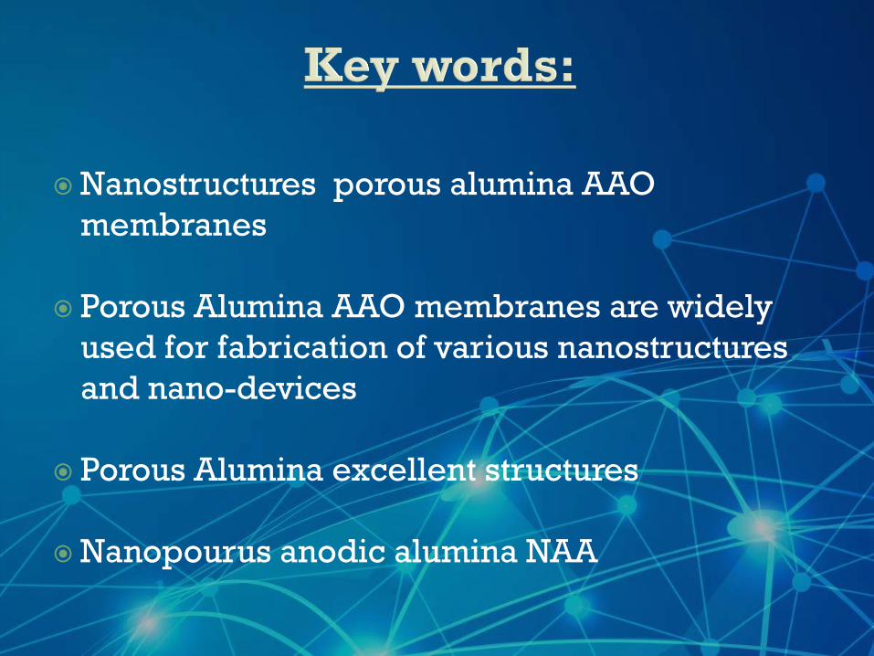
Nanostructures porous alumina AAO
membranes
Porous Alumina AAO membranes are widely
used for fabrication of various nanostructures
and nano-devices
Porous Alumina excellent structures
Nanopourus anodic alumina NAA
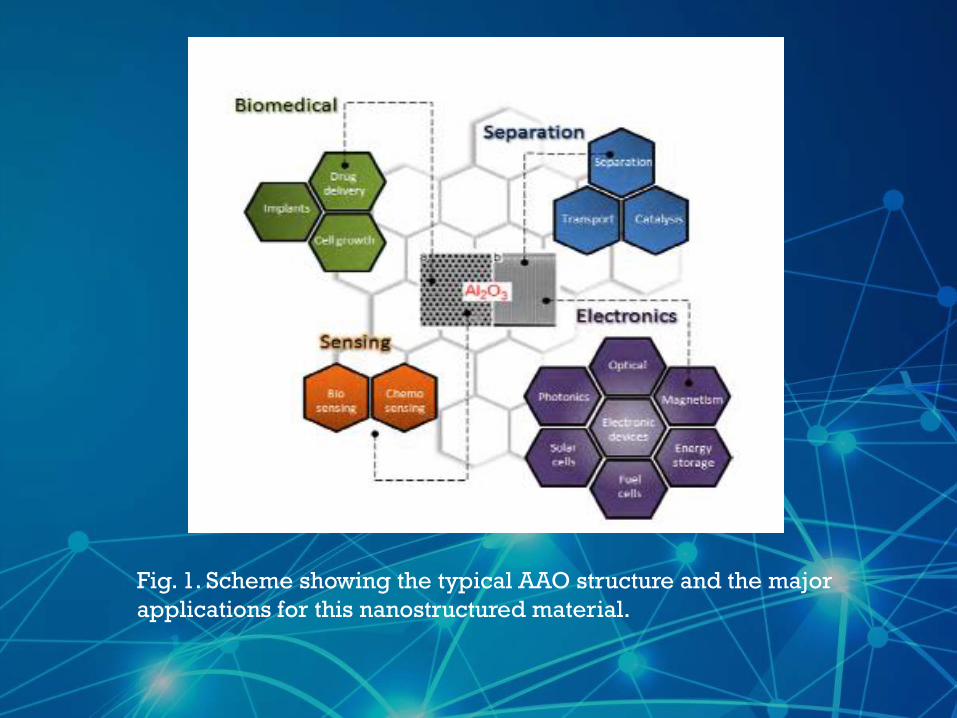
Fig. 1. Scheme showing the typical AAO structure and the major
applications for this nanostructured material.
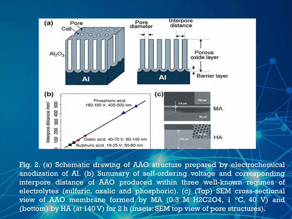
Fig. 2. (a) Schematic drawing of AAO structure prepared by electrochemical
anodization of Al. (b) Summary of self-ordering voltage and corresponding
interpore distance of AAO produced within three well-known regimes of
electrolytes (sulfuric, oxalic and phosphoric). (c) (Top) SEM cross-sectional
view of AAO membrane formed by MA (0.3 M H2C2O4, 1 °C, 40 V) and
(bottom) by HA (at 140 V) for 2 h (insets: SEM top view of pore structures).
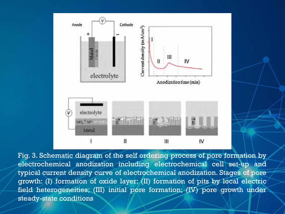
Fig. 3. Schematic diagram of the self ordering process of pore formation by
electrochemical anodization including electrochemical cell set-up and
typical current density curve of electrochemical anodization. Stages of pore
growth: (I) formation of oxide layer; (II) formation of pits by local electric
field heterogeneities; (III) initial pore formation; (IV) pore growth under
steady-state conditions
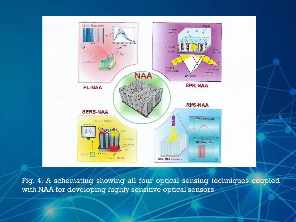
Fig. 4. A schemating showing all four optical sensing techniques coupled
with NAA for developing highly sensitive optical sensors
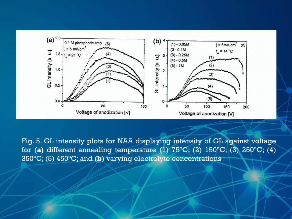
Fig. 5. GL intensity plots for NAA displaying intensity of GL against voltage
for (a) different annealing temperature (1) 75ºC; (2) 150ºC; (3) 250ºC; (4)
350ºC; (5) 450ºC; and (b) varying electrolyte concentrations
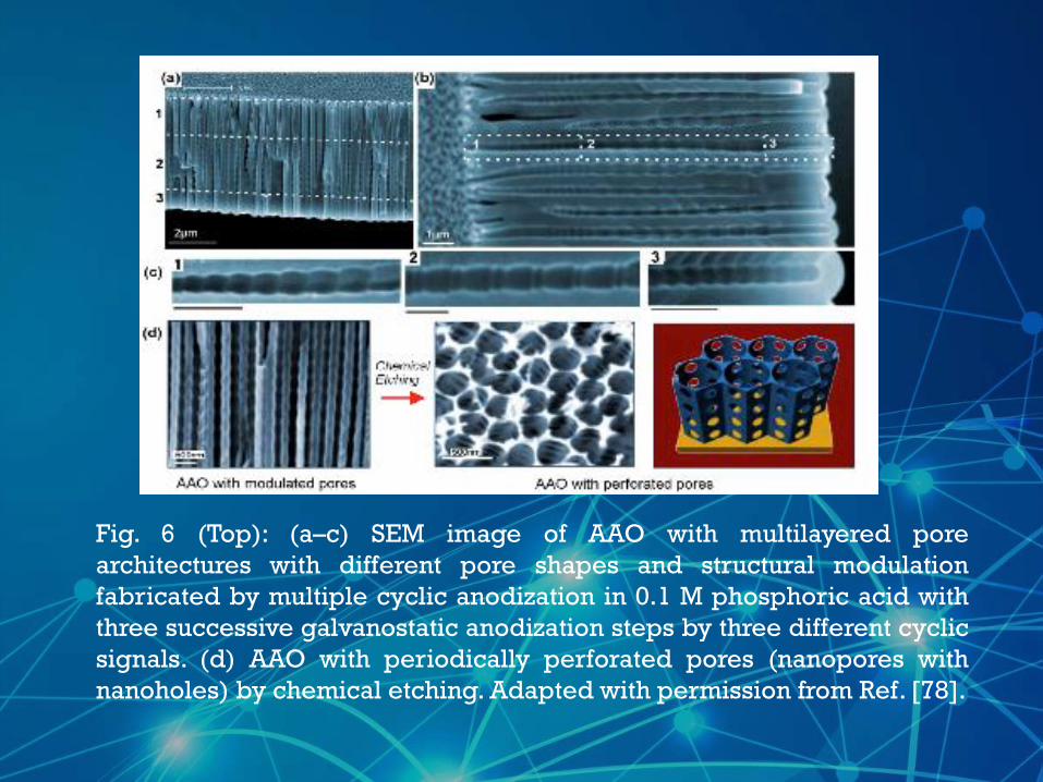
Fig. 6 (Top): (a–c) SEM image of AAO with multilayered pore
architectures with different pore shapes and structural modulation
fabricated by multiple cyclic anodization in 0.1 M phosphoric acid with
three successive galvanostatic anodization steps by three different cyclic
signals. (d) AAO with periodically perforated pores (nanopores with
nanoholes) by chemical etching. Adapted with permission from Ref. [78].
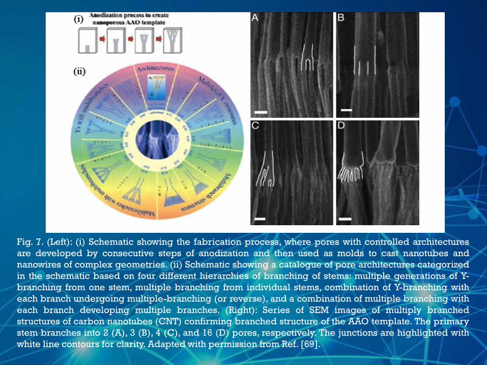
Fig. 7. (Left): (i) Schematic showing the fabrication process, where pores with controlled architectures
are developed by consecutive steps of anodization and then used as molds to cast nanotubes and
nanowires of complex geometries. (ii) Schematic showing a catalogue of pore architectures categorized
in the schematic based on four different hierarchies of branching of stems: multiple generations of Y-
branching from one stem, multiple branching from individual stems, combination of Y-branching with
each branch undergoing multiple-branching (or reverse), and a combination of multiple branching with
each branch developing multiple branches. (Right): Series of SEM images of multiply branched
structures of carbon nanotubes (CNT) confirming branched structure of the AAO template. The primary
stem branches into 2 (A), 3 (B), 4 (C), and 16 (D) pores, respectively. The junctions are highlighted with
white line contours for clarity. Adapted with permission from Ref. [69].
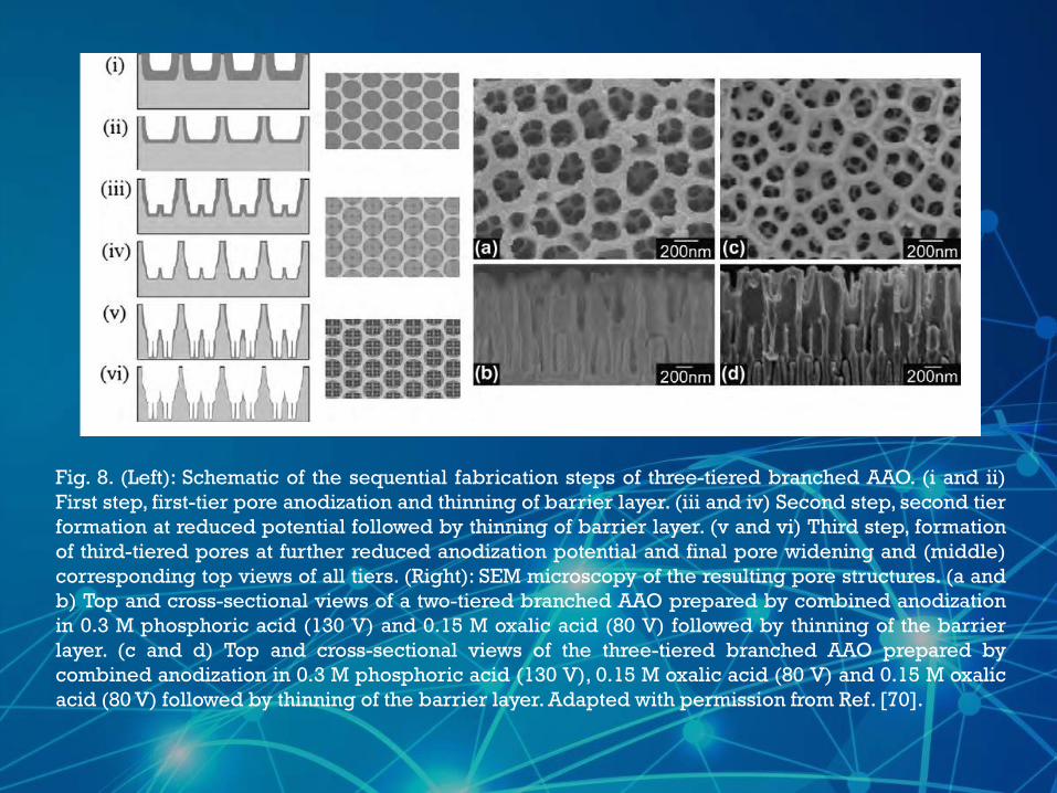
Fig. 8. (Left): Schematic of the sequential fabrication steps of three-tiered branched AAO. (i and ii)
First step, first-tier pore anodization and thinning of barrier layer. (iii and iv) Second step, second tier
formation at reduced potential followed by thinning of barrier layer. (v and vi) Third step, formation
of third-tiered pores at further reduced anodization potential and final pore widening and (middle)
corresponding top views of all tiers. (Right): SEM microscopy of the resulting pore structures. (a and
b) Top and cross-sectional views of a two-tiered branched AAO prepared by combined anodization
in 0.3 M phosphoric acid (130 V) and 0.15 M oxalic acid (80 V) followed by thinning of the barrier
layer. (c and d) Top and cross-sectional views of the three-tiered branched AAO prepared by
combined anodization in 0.3 M phosphoric acid (130 V), 0.15 M oxalic acid (80 V) and 0.15 M oxalic
acid (80 V) followed by thinning of the barrier layer. Adapted with permission from Ref. [70].

Fig. 9. (a) PL spectrum of NAA showing Fabry-Pérot fringes and step-wise
changes in PL on attachment of trypsin side the pores. (b) Typical PL setup
used for recording luminiscence of NAA substrate along with the FP fringes
that can be converted to PL
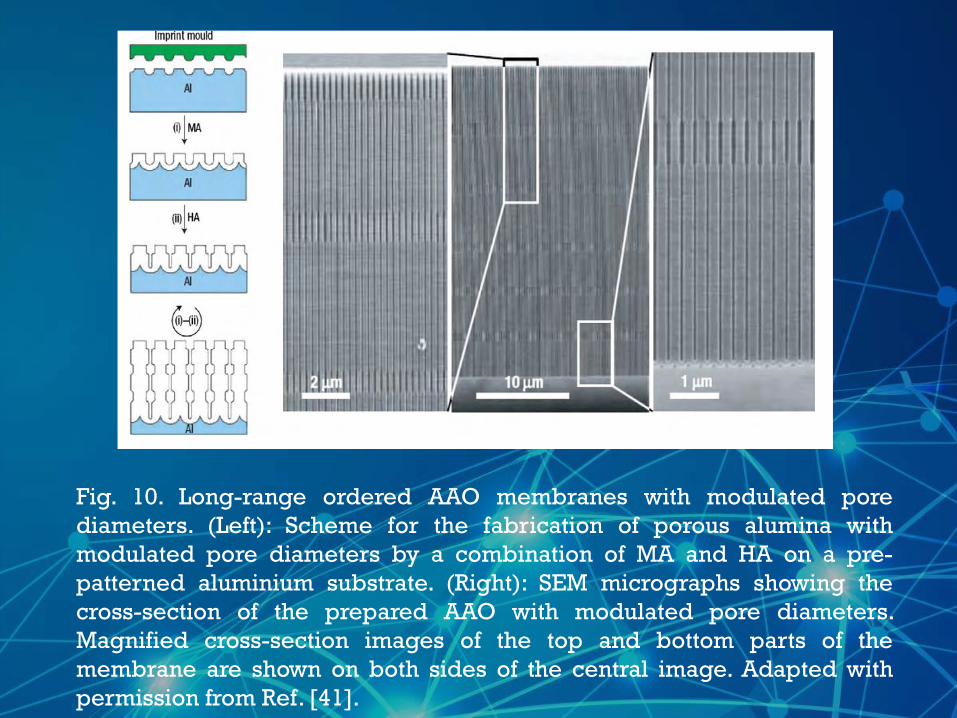
Fig. 10. Long-range ordered AAO membranes with modulated pore
diameters. (Left): Scheme for the fabrication of porous alumina with
modulated pore diameters by a combination of MA and HA on a pre-
patterned aluminium substrate. (Right): SEM micrographs showing the
cross-section of the prepared AAO with modulated pore diameters.
Magnified cross-section images of the top and bottom parts of the
membrane are shown on both sides of the central image. Adapted with
permission from Ref. [41].
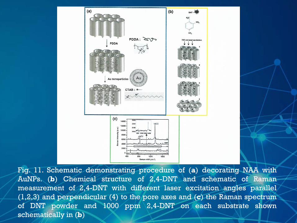
Fig. 11. Schematic demonstrating procedure of (a) decorating NAA with
AuNPs. (b) Chemical structure of 2,4-DNT and schematic of Raman
measurement of 2,4-DNT with different laser excitation angles parallel
(1,2,3) and perpendicular (4) to the pore axes and (c) the Raman spectrum
of DNT powder and 1000 ppm 2,4-DNT on each substrate shown
schematically in (b)
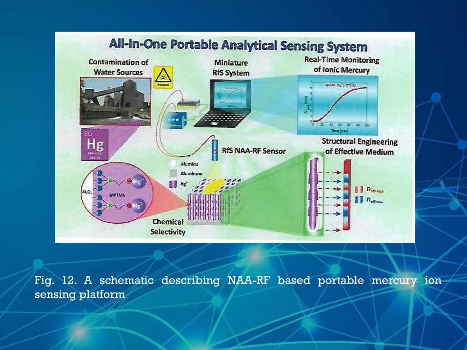
Fig. 12. A schematic describing NAA-RF based portable mercury ion
sensing platform
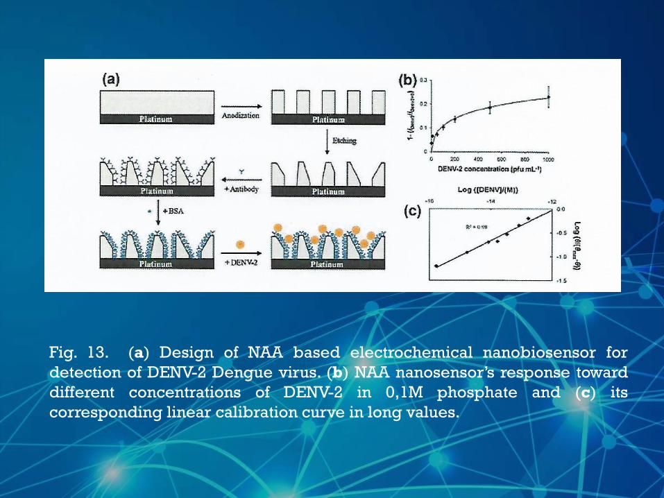
Fig. 13. (a) Design of NAA based electrochemical nanobiosensor for
detection of DENV-2 Dengue virus. (b) NAA nanosensor’s response toward
different concentrations of DENV-2 in 0,1M phosphate and (c) its
corresponding linear calibration curve in long values.
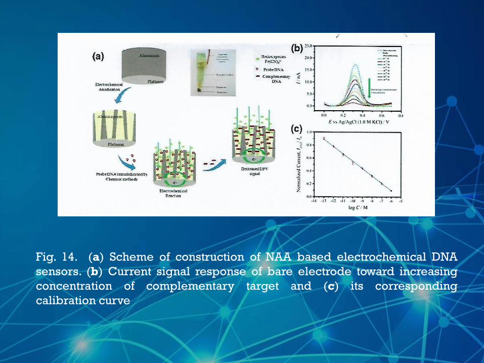
Fig. 14. (a) Scheme of construction of NAA based electrochemical DNA
sensors. (b) Current signal response of bare electrode toward increasing
concentration of complementary target and (c) its corresponding
calibration curve
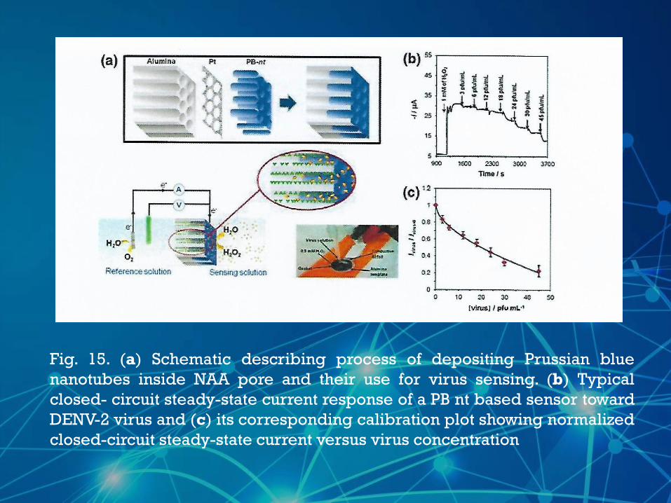
Fig. 15. (a) Schematic describing process of depositing Prussian blue
nanotubes inside NAA pore and their use for virus sensing. (b) Typical
closed- circuit steady-state current response of a PB nt based sensor toward
DENV-2 virus and (c) its corresponding calibration plot showing normalized
closed-circuit steady-state current versus virus concentration
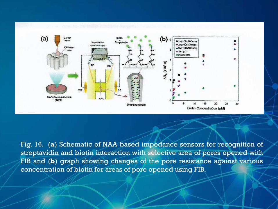
Fig. 16. (a) Schematic of NAA based impedance sensors for recognition of
streptavidin and biotin interaction with selective area of pores opened with
FIB and (b) graph showing changes of the pore resistance against various
concentration of biotin for areas of pore opened using FIB.
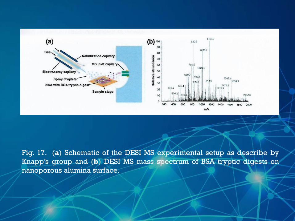
Fig. 17. (a) Schematic of the DESI MS experimental setup as describe by
Knapp’s group and (b) DESI MS mass spectrum of BSA tryptic digests on
nanoporous alumina surface.
Over the past several years, significant progress, has
been made, with regards to structural engineering and
surface modification of nanoporous AAO material.
Much of this progress has been application-driven. In
this review ,we have drawn together innovative
approaches on controlling and designing structural
growth of AAO with different sizes, arrangements,
structures ,geometries and pores architectures.
Access to these structures is achieved by changing
anodization conditions such as current ,voltage and
type of electrolytes during electrochemically self
ordering of AAO.
Researches are also pushing the boundaries of molecular separations using AAO with pores of controlled shape and size, internal surface modification and explore the effect external parameters, such as, pH, flux concentration gradient and ionic strength .
An excellent consistency between experimental results and theoretical predictions of the interpore distance was observed for the highest studied anodizing time and the highest ethanol content in the anodizing electrolyte.
Future reports on structural and chemical modifications of NAA will facilitate the development pf even smarter and advanced sensing devices
Fabricated rugate filters based on NAA using a pseudo-sinusoidal anodization profile, which results in a continues gradient in effective refractive index of the layer
Four different types of NAA rugate filters ( NAA –RF) were prepared varying the anodization parameters and most sensitive NAA-RF was selected by studying the shift in stop band peak
Applications for this nanostructured material for biomedical-separation-sensing and electronics
Schematic of a pore of AAO membrane modified by adsorption on two polyelectrolytes pf opposing charge
Schematic of a pore of AAO membrane modified by adsorption of two polyelectrolytes of opposing charge
Schematic of electrically-responsive electro-polymer-coated AAO membrane showing reversible change of pore size between oxidation and reduction states