combined source and channel coding of speech for
TRANSCRIPT

COMBINED SOURCE AND CHANNEL CODING OF
SPEECH FOR TELECOMMLNICATIONS
Guowen Yang
A THESIS SUBMITTED IN PARTIAL FULFILLMENT OF <
THE REQUIREMENTS FOR T H E DEGREE OF
MASTER O F APPLIED SCIENCE
in the School
of
Engineering Science
@ Guowen Yang 1990
Simon Fraser University
December, 1990
All rights reserved. This work may not be reproduced
in whole or in part, by photocopy or
other means, without permission of the author.

APPROVAL
NAME:
DEGREE:
TITLE OF THES
Guowen Yang
Master of Applied Science
IS: Combined Source and Channel Coding of
Speech for Telecommunications
EXAMINING COMMITTEE:
Chairman: Dr. Shawn Stapleton
Dr. Vladimir Cuperman
Senior Supervisor
Dr. Paul Ho
Senior Supervisor
r. James Cavers ?' Supervisor
John Bird
xaminer
DATE APPROVED: A p r i l 10, 1991

PARTIAL COPYRIGHT LICENSE
I hereby grant t o Simon Fraser Un ive rs i t y the r l g h t t o lend
my thesis, p ro jec t o r extended essay ( the t i t l e o f which i s shown below)
t o users o f the Simon f raser Unlvers l ty L ibrary, and t o make p a r t i a l o r
s i ng le copies only f o r such users o r i n response t o a request from the
l i b r a r y o f any other un ive rs i t y , o r o ther educational i n s t i t u t i o n , on
i t s own behalf o r f o r one of i t s users. I fu r ther agree t h a t permission
f o r mu l t l p l e copying of t h i s work f o r scho la r l y purposes may be granted
by me o r the Dean of Graduate Studies. I t i s understood t h a t copying
o r pub l lca t lon o f t h i s work f o r f i nanc ia l ga in sha l l not be allowed
wi thout my w r l t t en permission.
T i t l e of Thesis/Project/Extended Essay
"Combined Source And Channel Coding Of Speech For Telecommunications"
-
Author:
(signature)
Guowen Yang
(name 1
April 10, 1991
(date)

Abstract
Many efficient speech coding techniques to achieve high speech quality have been
developed for bit rates between 4.8 kbits/s and 16 kbits/s. Among these techniques,
Code Excited Linear Predictive (CELP) coding is a potential technique for providing
high quality speech at very low bit rates. In the absence of channel errors, the CELP
coder can produce high quality speech at bit rates as low as 1.8 ~&s/s. In the
presense of channel errors, however, the speech quality degrades dramatically. In
order to improve speech quality without increasing the transmission rate for given
channel conditions, we study combined source and channel coding of speech using
CELP coding and Punctured Convolutional (PC) coding in this thesis. Based on
the information- transmission theorem, this thesis derives the performance b o a d of
the CELP coder in an Additive White Gaussian Noise (AWGN) channel and an
interleaved Rayleigh fading channel. This performance bound provides a reference
for the performance of a practical combined CELP and PC coder. To arrive at an
efficient combined coder, different levels of error protection are applied to different
bits of the CELP coder's output according to bit error sensitivities. Simulation results
show that at the bit error rate of the combined coder can obtain up to a 10
dB improvement in the AWGN channel and a 12 dB improvement in the Rayleigh
fading channel, with respect to the CELP coder without channel coding a t the same
transmission rate. These improvements are measured in terms of the segmental signal
to noise ratio of the reconstructed speech.

Acknowledgements
I would like to thank my supervisors, Dr. Vladimir Cuperman and Dr. Paul Ho,
for their assistance, encouragement and guidance throughout the course of this
research. I am also thankful to Dr. Rong Peng and Prof. Zhixin Yan for their helpful
comments on this thesis. Finally, I would like to thank Mr. Tamas Revoczi of the
CJIV radio station at Simon Fraser University for his proofreading of this thesis.
LJ This research was supported in part by an NSERC strategic grant and in part by
a B.C. Science Council's AGAR grant.

For my wife and parents

Contents
. , .4pproval . . . . . . . . . . . . . . . . . . . . . . . . . . . . . . . . . . . . . . 11
. . . A b s t r a c t . . . . . . . . . . . . . . . . . . . . . . . . . . . . . . . . . . . . . . . 111
Acknowledgements.. . . . . . . . . . . . . . . . . . . . . . . . . . . . . . . . v
List of Figures . . . . . . . . . . . . . . . . . . . . . . . . . . . . . . . . . . . xii
... List of Tables . . . . . . . . . . . . . . . . . . . . . . . . . . . . . . . . . . . . xi11
Abbreviation . . . . . . . . . . . . . . . . . . . . . . . . . . . . . . . . . . . .\iv
1 Introduction 1
2 Source Coding and Channel Coding Techniques 5
2.1 Model of a Combined Source and Channel Coding System . . . . . . 6
2.2 Source Coding . . . . . . . . . . . . . . . . . . . . . . . . . . . . . . . S
2.2.1 DataCompression . . . . . . . . . . . . . . . . . . . . . . . . 9
2.2.2 Source Coding Techniques . . . . . . . . . . . . . . . . . . . . 10
2.3 Noisy Channels . . . . . . . . . . . . . . . . . . . . . . . . . . . . . . 13
2.3.1 Additive White Gaussian Noise Channel . . . . . . . . . . . . 13
vi

2.3.2 Rayleigh Fading Channel . . . . . . . . . . . . . . . . . . . . 14
2.4 Channel Coding . . . . . . . . . . . . . . . . . . . . . . . . . . . . . . 15
2.5 Combined Source and Channel Coding . . . . . . . . . . . . . . . . . 17
3 Speech Coding Algorithm 21 *
3.1 Introduction . . . . . . . . . . . . . . . . . . . . . . . . . . . . . . . . 21
3.2 Objective Performance Measures . . . . . . . . . . . . . . . . . . . . 22
3.3 Basic Structure of a CELP Coder . . . . . . . . . . . . . . . . . . . . 24
3.4 VQCELP Coder Algorithm . . . . . . . . . . .
3.5 Parameter Quantization and Bit Allocation . . . . . . . . . . . . . . . 30
3.5.1 Short-Term Predictor . . . . . . . . . . . . . . . . . . . . . . . 30 7
. . . . . . . . . . . . . . . . . . . . . . . 3.5.2 Long-Term Predictor 31
. . . . . . . . . . . . . . . . . . . . . . 3.5.3 Excitation Parameters 32
3.6 Bit Allocations for VQCELP Coders a t 4.S and 6.4 kbits/s . . . . . . 33
4 Performance Bound of the VQCELP Coder Over the AWGN Chan-
nel and the Rayleigh Fading Channel 35
. . . . . . . . . . . . . . . 4.1 Autoregressive Model for the Speech Signal 36
. . . . . . . . . . . . . 4.2 Rate-Distortion Function of the Speech Signal 37
4.3 Cutoff Rate for the AWGN Channel and the Ray-leigh Fading Channel
. . . . . . . . . . . . . . . . . . . . . . . with the BPSIi modulation 39
vii

4.4 Performance Bound of the VQCELP Coder in the AII'G?; Channel
and the Rayleigh Fading Channel . . . . . . . . . . . . . . . . . . . .
5 Combined Source a n d Channe l Cod ing
5.1 Observations and Motivations . . . . . . . . . . . . . . . . . . . . . .
5.2 Evaluation of Bit Error Sensitivity . . . : . . . . . . . . . . . . . . .
5.3 Combined Source and Channel Coding Configuration . . . . . . . .
5.4 Punctured Convolutional Codes . . . . . . . . . . . . . . . . . . . . .
. . . . . . . . . . . . . . . . . . . . . . . . . . . . 5.4.1 Introduction
. . . . . . . . . . . . . . . . . . . . . . . 5.4.2 Convolutional Codes
5.4.3 Punctured Convolutional Codes . . . . . . . . . . . . . . . . .
5.4.4 Performance of Punctured Convolutional Codes in the Gaus-
sian channel and the Rayleigh Fading Channel . . . . . . . . .
. . . . . . . . . . . . . . . . . . . . . . 5.5 Optimal Code Rate Allocation
5.5.1 Full Search for the Optimal Rate Allocation . . . . . . . . . .
. . . . . . . . 5.5.2 Partial Search for the Optimal Rate Allocation
6 Experimental Resu l t s
6.1 Experimental Combined VQCELP and P C Coding System . . . . . .
. . . . . . . . . . . . . . . . . . . 6.2 VQCELP Coder in Noisy Channels
. . . . . . . . . . . 6.3 Improvement of the VQCELP Coder's Robustness

6.4 Performance of the Combined VQCELP and P C Coder in the AM7GN . . . . . . . . . . . . . . . . . . . . . . . . . . . . . . . . . . Channel 79
6.S Performance of the Combined VQCELP and P C Coder in the Rayleigh
. . . . . . . . . . . . . . . . . . . . . . . . . . . . . . Fading Channel S4
6.5.1 Performance in the Rayleigh Fading Channel with Infinite In-
. . . . . . . . . . . . . . . . . . . . . . . . . . . . . terleaving 84
6.5.2 Performance in the Rayleigh Fading Channel with Finite In-
. . . . . . . . . . . . . . . . . . . . . . . . . . . . . terleaving S7
7 Conclusions and Future Studies 9 5
Bibliography

List of Figures
2.1 Model of a combined source and channel coding system . . . . . . . . 7
2.2 Block diagram of a source coding system . . . . . . . . . . . . . . . . 10
2.3 Block diagram of a channel coding system . . . . . . . . . . . . . . . . 16
3.1 A simple block diagram of speech coder . . . . . . . . . . . . . . . . . 23
3.3 VQCELP coder with complexity reduction . . . . . . . . . . . . . . . 27
a . . . . . . . . . . . . . . . . . . . . . . . . . . . 4.1 Speech source model 38
4.2 Cutoff Rate of the AWGN channel versus Es/No . . . . . . . . . . . . 40
4.3 Cutoff Rate of the Rayleigh fading channel versus Es/No . . . . . . . 41
4.4 The SSNR bound versus the channel Es/No on the AWGN channel . 45
4.5 The SSNR bound versus the channel Es/No on the Rayleigh fading
. . . . . . . . . . . . . . . . . . . . . . . . . . . . . . . . . . channel 46
5.1 Performance of a 6.4 kbits/s VQCELP coder in the AWGN channel . 49
. . . . . . . . . . 5.2 Bit error sensitivities of a VQCELP coder's output 52
5.3 Combined source and channel coding configuration . . . . . . . . . . 54
Information bits grouped according to their relative sensitivities . . . 55
A rate 1/2 convolutional encoder with a constraint length of 2 . . . . 57
Basic procedure of punctured coding from rate l /n convolutional code 59
An example of bit arrangement according to bit error sensitivities for
a 6.4 kbit/s combined coder . . . . . . . . . . . . . . . . . . . . . . . 66
SSNR versus code rate allocation at E , / N , = 6 dB on an interleaved
Rayleigh fading channel . . . . . . . . . . . . . . . . . . . . . . . . . 68
An example of the partial search . . . . . . . . . . . . . . . . . . . . 69
Block diagram of a combined VQCELP and PC coder . . . . . . . . . 74
Performance of the 6.4 kbits/s VQCELP coder in the AWGN channel 77
Performance of the 6.4 kbits/s VQCELP coder in the Rayleigh fading
channel . . . . . . . . . . . . . . . . . . . . . . . . . . . . . . . . . . 78
Bit sensitivity of the 4.8 kbits/s VQCELP coder . . . . . . . . . . . . 80
Improved bit sensitivity of the 4.8 kbits/s VQCELP coder . . . . . . 81
Error protection capability of rate 112, 2/3, and 314 punctured codes
in the AWGN channel . . . . . . . . . . . . . . . . . . . . . . . . . . 83
Performance of the combined VQCELP-PC coder in the AWGN channel 85
Error correction capacity of rate 112, 2/3, and 3/4 punctured codes in
the interleaved Rayleigh fading channel . . . . . . . . . . . . . . . . . SS
Performance of the combined VQCELP-PC coder in the Rayleigh fad-
ing channel with infinite interleaving . . . . . . . . . . . . . . . . . . 89

6.10 Performance of the combined VQCELP-PC coder in the Rayleigh fad-
ing channel with finite interleaving . . . . . . . . . . . . . . . . . . . 91
xii

List of Tables
3.1 Bit allocation for a 6.4 kbps VQCELP coder . . . . . . . . . . . . . 34
3.2 Bit allocation for a 4.8 kbps VQCELP coder . . . . . . . . . . . . . . 34
. . . . . . . . . . . . . . . 5.1 Examples of punctured convolutional codes 60
5.2 Optimum puncturing maps for rate (n-l)/n punctured codes . . . . . 64
. . . . . . . . . . . . 6.1 Map for rate 112. 213 and 314 punctured codes 92
. . . . . . 6.2 Rate allocation for E. /No = 1.3 dB in the AWGN channel 93
6.3 Rate allocation for E. /No = 6.0 dB in the interleaved Rayleigh fading
. . . . . . . . . . . . . . . . . . . . . . . . . . . . . . . . . . channel 94

Abbreviation
ADPCM Adaptive Differential Pulse Code Modulation
APCM 1 Adaptive Pulse Code Modulation
AVPC Adaptive Vector Predictive Coding
AWGN Additive White Gaussian Noise
BER Bit Error Rate
BPSK Binary Phase Shift Keying
CELP Code Excited Linear Predictive
CSI Channel State Information
dB decibel
DPCM Differential Pulse Code Modulation
DSP Digital Signal Processor
FEC Forward Error Correction
LPC Linear Predictive Coding
LSP Line Spectrum Pairs
MSE Mean Square Error
PC Punctured Convolutional
PCM Pulse Code Modulation
RCPC Rate Compatible Punctured Convolutional
SNR Signal to Noise Ratio
SSNR Segmental Signal to Noise Ratio
VA Viterbi Algorithm
VQ Vector Quantization
VQCELP Vector Quantized Code Excited Linear Predictive
VQCELP-PC Vector Quantized Code Excited Linear Predictive
xiv
VXC
ZIR
ZSR
and Punctured Convolutional
Vector Excited Coding
Zero Input Response
Zero State Response

Chapter 1
Introduction
Digital transmission of speech is becoming more prevalent in telecommunications be-
cause it provides numerous advantages such as the compatibility with data transmis-
sion, the use of modern transmission techniques, and the encryption of transmitted
speech throughout digital networks. In recent years, there has been much activity
in digital transmission of speech for mobile radio applications. For instance, the
Department of Defense (DoD) has been developing a secure voice system where the
speech transmission rate is 4.8 kbits/s [I]. Since 1984, NASA has been exploring the
feasibility of speech coding at the rate of 4.8 kbits/s for NASA's Mobile Satellite Ex-
periment (MSAT-X) [2]. The Telecommunications Industry Association has recently
initialized the North American digital cellular standard. In this new standard, the
speech signal is transmitted at a gross bit rate of 13 kbits/s [3]. For mobile radio
applications, speech coders are required to have low bit rates and to provide high
quality speech. Many efficient speech coders have been developed for providing high
quality speech at bit rates between 4.8 kbits/s and 16 kbits/s [2, 4, 5 , 11, 231. How-
ever, the application of such low bit rate speech coders to mobile radio systems can
lead to a significant degradation in speech quality, because of the frequent occurrence
of severe transmission errors caused by adjacent channel interference and multipath
fading. Thus, the characteristics required for speech coders applied to mobile commu-

nications are low bit rates, high quality and robustness to channel errors which may
be random or in bursts. Motivated by digital transmission of high quality speech
in mobile radio applications, we study in this thesis combined source and channel
coding of speech through Gaussian-noise and Rayleigh-fading channels.
Research advances in speech coding have shown that Code Excited Linear Pre-
dictive (CELP) coding is a very promising technique for transmission of high quality
speech at low bit rates [2, 4, 5, 61. Therefore, there exist considerable interests in
the application of the CELP coding to mobile radio communications. In a CELP
coder, the speech signal is represented by parameters, such as LPC coefficients, pitch
period, pitch gain, excitation codeword and excitation gain. These parameters are
quantized, coded, and transmitted over a physical channel, such as a tele one line, I satellite link, or mobile radio channel. In the absence of channel errors, the CELP
coder produces good quality speech at bit rates as low as 4.8 kbits/s [4, 6, 111. In
the presence of channel errors, however, the reconstructed speech quality degrades
dramatically. Efficient index assignment [7, 8, 91, parameter smoothing with error
detection [lo, 121, and Forward Error Correction (FEC) [13, 14, 15, 161 are possi-
ble techniques for improving the reproduced speech quality under noisy conditions.
Efficient index assignment assumes that only one bit error occurs in a binary code
representing a codeword index. This may not be the case in a harsh channel with
a high bit error rate and/or burst errors. The parameter smoothing is based on the
error detection applied to a binary code representing a parameter. If any error is
detected, the current parameter value is replaced by the previous one or interpolated
with the previous two or more values. In the case of a high bit error rate or burst
errors, errors may be detected for the same parameter in consecutive frames. This
causes very audible glitches, squeaks or blasts because the parameter smoothing is
based on incorrect values. FEC is a technique for improving communications per-
formance by transmitting redundancy, that is, expanding bandwidth. The channel
coding theorem [17, 181 states that the transmitted information data can be recov-
ered at the receiver with arbitrarily small probability of error as long as the channel
capacity C is greater than the information rate R. At a given channel signal to noise
ratio, the channel capacity increases with the bandwidth expansion [19]. Thus, FEC
can be effective for improving speech quality in very noisy environments if the chan-
nel bandwidth expansion is large enough such that the channel capacity C is greater
than the information rate R.
For mobile radio applications, channel bandwidth is a scarce resource, and people
prefer to avoid expanding channel bandwidth or increasing the total transmission
rate. In order to improve speech quality without increasing the transmission rate,
this thesis studies combined source and channel coding of speech using Vector Quan-
tized CELP (VQCELP) coding and Punctured Convolutional coding (PC). In this
combined coding system, the trade-off between source coding and channel coding is
made according to the channel condition. We have carefully examined the bit error
sensitivity of the VQCELP coder's output and have found that there exists a large
dynamic range of bit error sensitivity among the output bits. To arrive a t an efficient
combined coder, different levels of error protection are applied to the different output
bits of the speech coder according to the bit error sensitivities. PC coding is capable
of providing different levels of error protection with one codec. This feature of the I
PC coding results in simple combined VQCELP and PC (VQCELP-PC) codecs.
The Segmental Signal to Koise Ratio (SSNR) between the original speech and
the reconstructed speech is used as an objective performance measure in this thesis.
To provide a performance reference for practical combined VQCELP-PC coders, the
performance bound of the VQCELP coder on noisy channels is calculated based on
the information- transmission theorem [19]. Previously, combined source and channel
coding has been studied for simple waveform coders such as 32 kbits/s DPCM [13] or
16 kbits/s subband coder [15]. In those systems, the channel code rate allocation is
not optimally designed under certain distortion criterion, such as the mean squared
error or the SSNR of the reconstructed speech. Both the full search method and
a partial search algorithm for finding the optimal channel code rate allocation are
discussed in this thesis. Simulation results show that at a bit error rate as high as
the combined VQCELP-PC coder can obtain up to a 10 dB improvement on
an Additive White Gaussian Noise (AWGN) channel and a 12 dB improvement on

an interleaved Rayleigh fading channel, with respect to the VQCELP coder without
channel coding at the same transmission rate. Note that the improvements are mea-
sured in terms of the SSNR of the reconstructed speech. Informal listening tests show
that in very noisy channels, the speech quality obtained by the combined VQCELP-
PC coder has a substantial improvement over the speech quality provided by the
VQCELP coder without channel coding at the same transmission rate.
The organization of this thesis is as follows. Chapter 2 describes the system model
used in this study and gives an overview of the combined source and channel coding
techniques. The basic CELP coder structure and a reduced complexity VQCELP
coder are described in Chapter 3. Parameter quantizations and bit allocations are
also discussed in Chapter 3. Based on the information-transmission theorem, the
performance bound of the VQCELP coder under noisy conditions is calculated in
Chapter 4. Chapter 5 describes a technique for the evaluation of bit error sensitivity
and introduces a combined source and channel coding configuration. This configu-
ration takes into account the bit error sensitivities of the source coder's output. In
the same chapter, PC coding is described and the methods for finding the optimal
channel rate allocation are discussed. Experimental results are provided in Chapter
1 6. Finally, Chapter 7 gives some conclusions and recommendations for future studies.

Chapter 2
Source Coding and Channel
Coding Techniques
The purpose of source coding is to transform an analog source signal into a digital
sequence. The goal of channel coding is to reliably transmit the digital sequence 1 from the source encoder to the source decoder over a noisy channel. As implied by
its title, this thesis concerns both source coding and channel coding. Before having
a detailed discussion on combined source and channel coding, an overview of source
coding techniques, and channel coding techniques is necessary. This chapter begins
with a description of the basic block diagram of a combined source and channel
coding system in Section 2.1. Section 2.2 follows with an overview of source coding
techniques. Gaussian-noise and Rayleigh-fading channels are described in Section 2.3.
Channel coding techniques are outlined in Section 2.4. Section 2.5 gives an overview
of various combined source and channel coding methods.

2.1 Model of a Combined Source and Channel
Coding System
A combined source and channel coding system may be represented by the block
diagram shown in Fig. 2.1. The function of the system is to transmit the messages
coming out of an information source to a destination user as accurately as possible.
Information sources can be classified into two categories: analog information sources
and discrete information sources. An analog information source can be transformed
into a discrete-time and discrete-amplitude information source through the process
of sampling and quantizing.
The source encoder transforms the source output, denoted by is,) into a sequence
of binary digits (bits) called the information sequence u. Ideally one would like
to represent the source output by as few binary digits as possible. Techniques for
efficiently transforming the output of a source into a sequence of binary digits are
outlined in Section 2.2. 1 The channel encoder transforms the information sequence u into another sequence
v called a codeword. Some redundancy is introduced in the codeword. The redun-
dancy is introduced for the purpose of combating the detrimental effects of noise
and interference and thus increasing the reliability of the data transmitted through
channels. The codeword v can be either a binary sequence or an M-ary sequence in
different applications. We only consider the case of a binary sequence in this the-
sis. In our combined coding system, the channel encoder will encode the information
sequence u by taking into account the bit significance of the information sequence u.
The sequence of binary digits from the channel encoder is to be transmitted
through a physical channel to the destination user. However, binary digits are not
suitable for direct transmission over a physical channel. The modulator transforms
each output digit of the channel encoder into a waveform which is suitable for trans-
mission. This waveform enters the channel and is corrupted by noise. At the receiving

Source
Fig. 2.1 Model of a combined source and channel coding system
r(t) u . 1
il
Source encoder
s(t)
no>
Demodulator
U
Noise
Channel decoder
- Channel Modulator encoder
Channel
User ,
Source decoder 4 - -'

end, the demodulator processes each received waveform and produces an output that
may be digital (quantized) or continuous (unquantized). We call the demodulated
sequence corresponding to the encoded sequence, v, the received sequence, r.
The channel decoder transforms the received sequence r into a bir-ary sequence
ii called the estimated sequence. The channel decoder uses the redundancy in a
codeword to correct the errors in the received sequence r. Ideally, ii will be a replica
of the information sequence u, although the noise may cause some errors in the
received sequence r.
The source decoder reconstructs the source output from the estimated sequence ii
and delivers it to the destination. Due to the decoding errors, and possible distortion
introduced by the source codec, the reconstructed source signal, denoted by {in}, is
an approximation to the original source signal {s,}. Thus the distortion between the
reconstructed source signal and the original source signal depends on source encoding,
channel encoding, channel noise, channel decoding, and source decoding. In this
study, the source codec is a VQCELP codec, and the channel codec is a punctured
convolutional codec. These codecs will be discussed in Chapter 3 and Chapter 5, I respectively.
2.2 Source Coding
The speech signal is an analog signal , which is continuous in both time and ampli-
tude. The Nyquist sampling theorem 1191 provides a link between continuous-time
signals and discrete-time signals. The sampling theorem states that if the analog
source signal is a band-limited process, the sampling performed at the Nyquist rate
or faster does not result in a loss of information. The speech signal is assumed to be
band-limited to the frequency range 200 to 3200 Hz. In the encoding of the speech
signal, the first step usually involves sampling the speech signal periodically. The
sampling process converts the analog speech signal into an equivalent discrete-time
signal denoted {s,). The speech signal {s,) is always assumed to be discrete-time

and continuous-amplitude hereafter
2.2.1 Data Compression
The continuous amplitude signal {s,) requires an infinite number of binary digits
to represent it exactly. Hence, the entropy H(S) of {s,) is infinite. In Shannon's
original papers on information theory [17, 181, the converse to the channel coding
theorem states that it is impossible to reproduce {s,) at the receiver with arbitrarily
small distortion when H ( S ) > C, where C is the capacity of a channel. In practice
a channel with the infinite capacity C does not exist. Therefore, it is impossible
to reconstruct the continuous amplitude speech signal {s,} with arbitrarily small
distortion.
According to the rate-distortion theorem, the entropy H(S) of the speech signal
{s,) can be reduced by transforming the speech signal {s,} into its approximation
(3,) such that H(S) 5 C. Then, the channel coding theorem states that the signal
{in) with the entropy H(S) can be reconstructed a t the receiver with an arbitrarily ) small distortion. The operation for transforming the speech signal {s,) into its
approximation {S,) is referred as to data compression or source coding. The data
compression is obtained a t the cost of some distortion between the original signal
and the reconstructed signal. A block diagram of speech coding system is depicted
in Fig. 2.2. The source encoder converts a sample or a block of samples of the speech
signal {s,} into a binary sequence u. In source coding, the channel is assumed to
be noiseless, i.e., the estimated binary sequence G is identical to the information
sequence u. The source decoder reconstructs the speech signal from the estimated
binary sequence G. The reconstructed speech signal is denoted by in. An objective
in speech coding is to minimize the number of bits of u for a given level of tolerable
distortion d(s,, 3,) between the original speech signal {s,) and the reconstructed one
(3,). The distortion d(s,, in) can be any real-valued distortion measure, such as the
mean squared error or the SSNR of the reconstructed speech. In other words, speech
coding attempts to minimize the distortion d(s,,i,) for a binary sequence u with a

Source Noiseless il
Source 1
User Channel decoder
Figure 2.2: Block diagram of a source coding system
given number of bits.
2.2.2 Source Coding Techniques 1 Encoding of the sampled speech signal results in data compression but it also in-
troduces some distortion of the signal or a loss of signal fidelity. The attempt in
minimizing this distortion has resulted in an evolution of speech encoding techniques.
Pulse Code Modulation (PCM) is the simplest speech encoding technique. In
PCM each sample of the speech signal is independently quantized to one of the 2b
amplitude levels, where b is the number of binary digits used to represent each sample.
Since speech signals sampled at the Nyquist rate or faster exhibit significant correla-
tion between successive samples, it is more efficient to encode the differences between
successive samples rather than the samples themselves as was done in the PCM sys-
tem. This observation leads to the development of Differential PCM (DPCM). In
DPCM, the current sample is predicted based on the previous p samples, where p is
typically between 1 and 16, and the difference between the current sample and its

predicted value is quantized. The speech signal is quasi-stationary in nature. The
variance and the autocorrelation function of the speech signal vary slowly with time.
PCM and DPCM encoders, however, are designed on the basis that the source output
is stationary. The efficiency and performance of these encoders can be improved by
having them adapt to the slowly time-varying statistics of the speech signal. In PCM,
the quantization error resulting from a uniform or nonuniform quantizer operating on
the quasi-stationary speech signal will have a time-dependent variance. One method
for reducing the quantization noise is the use of an adaptive quantizer. This technique
is called adaptive PCM (APCM). A relatively simple method is to use a uniform or
nonuniform quantizer which varies its step size in accordance with the variance of
the past speech samples. In DPCM, both the quantizer and the predictor can be
made adaptive, which leads to adaptive DPCM (ADPCM). The coefficients of the
predictor can be changed periodically to reflect the changing statistics of the speech
signal. PCM, DPCM, APCM and ADPCM are all speech encoding techniques that
attempt to faithfully represent the speech waveform. Consequently these methods
are classified as waveform encoding techniques.
In contrast to the waveform encoding techniques, linear predictive coding (LPC) ) represents a completely different approach to the problem of speech encoding. In LPC
the speech signal is modeled as the output of a linear system excited by an appropriate
input signal [20, 21, 221. Instead of transmitting the samples of the speech signal to
the receiver, the parameters of the linear system are transmitted along with the
appropriate excitation signal. In LPC the sampled sequence is assumed to have been
generated by an all-pole filter having the transfer function
where ak, k = 1, . -., p, are the coefficients of the linear system, p is the order of
the all-pole filter and G is a gain factor. Appropriate excitation functions are a
sequence of impulses, or a sequence of white noise with unit variance. Suppose that
the excitation sequence is denoted as v,, n = 0, 1, . . .. Then the output sequence of
the all-pole model satisfies the difference equation
At the encoder, we may form a prediction of s, by the linear combination
The error between the observed value s, and the predicted value in, usually called
residual, is
The filter coefficients ak, k=l , . -, p, can be estimated by forward adaptation or
backward adaptation. In the forward adaptation, the predictor parameters are com-
puted in the encoder, using the original speech signal, and then transmitted to the
decoder as side information. In the backward adaptation, the prediction parameters
are estimated at both the encoder and decoder from the reconstructed speech signal.
In the above encoding techniques, the speech signal (in PCM and APCM) or the 1 residual signal (in DPCM, ADPCM and LPC) is quantized on a sample-by-sample
basis, i.e., by scalar quantization. A fundamental result of rate distortion theory is
that better performance can be achieved by quantizing vectors instead of scalars, even
if the continuous-amplitude source is memoryless. When a block or vector of samples
is jointly quantized, this process is called Vector Quantization (VQ). The combination
of vector quantization with linear predictive coding results in more efficient speech
coding algorithms, such as Adaptive Vector Predictive Coding (AVPC) [23], Code
Excited Linear Predictive (CELP) coding [4,5], and Vector Excitation Coding (VXC)
[2]. The CELP coder is employed in this study and is discussed in detail in next
chapter.

2.3 Noisy Channels
In the source encoding, a noiseless channel is usually considered. However, this is
not the case in a real channel. Typical transmission channels include telephone lines,
mobile radio links, microwave links, satellite links, and so on. These channels are
subject to various types of noise disturbances. On a telephone line, for instance, the
disturbance may come from switching impulse noise, thermal noise, crosstalk from
other lines, or lightning. The channel itself is a waveform channel. As shown in Fig.
2.1, the modulator serves as the interface that accepts a digital information sequence
at its input and puts out a set of corresponding waveforms. Similarly, the demodulator
at the receiving end serves as the interface between the waveform channel and the
digital channel decoder. Hence the demodulator accepts waveforms a t its input,
processes the waveforms, and delivers to the channel decoder a sequence of digital
symbols (hard decision decoding) or discrete-time symbols (soft decision decoding).
Binary Phase Shift Keying (BPSK) is a commonly used modulation technique. In this
study, we assume that the BPSK is used. We also assume that coherent demodulation
and perfect carrier recovery can be achieved a t the receiver. Techniques for carrier
recovery and coherent BPSM demodulation are well documented in literature, for
instance, 124, 251. In an analysis of communication systems, the baseJhd equivalent
channel can be considered without loss of generality. The additive white Gaussian
noise channel and the Rayleigh fading channel will be briefly described in this section.
These two channel models will be used throughout this thesis.
2.3.1 Additive White Gaussian Noise Channel
The Additive White Gaussian Noise (AWGN) channel is the most commonly used
channel model in the analysis of communication systems. For the AWGN channel,
the baseband equivalent of the received signal can be expressed as

where s(t) is the baseband equivalent of the transmitted signal and n(t) is a zero
mean, complex Gaussian channel process with a power spectral density of N0/2. A
coherent BPSK demodulator consists of a matched filter and a sampler. The output
of the demodulator can be written as
where rk, sk, and nk denote the sampled value of r( t ) , s( t ) and n(t) during the kth
interval. Note that for BPSK, sk is either (A, 0) or (-A, 0) on the complex plane
in accordance with the input data of "1" or "0" to the modulator, where A is the
signal amplitude. In Eq.(2.6), nk is a complex Gaussian noise variable with zero mean
and variance of oH=N0/2. In the case of hard decision decoding, each demodulated
sample r k is mapped into the most likely binary digit before being fed to the channel
decoder. For soft decision decoding, the demodulated sample r k is directly fed to the
channel decoder.
2.3.2 Rayleigh Fading Channel
For mobile radio applications, the channel is usually modeled as a Rayleigh fading
channel. On a Rayleigh fading channel, the baseband equivalent of the received signal
can be expressed as [26, 271
where g(t) is a zero mean, complex, Gaussian fading process, s(t) is the baseband
equivalent of the transmitted signal and n(t) is a zero mean, complex Gaussian noise
process with a power spectral density of No. g(t) physically represents the channel
fading process. We assume that g(t) has a normalized autocorrelation function [26]
where Jo(.) is the Bessel function of the first kind and order zero, and fD is the
maximum Doppler frequency. The parameter fD can be expressed in terms of the

vehicle speed v and the carrier frequency f, as
where c is the speed of light. Similarly as in the AWGN channel, a coherent demodu-
lator consists of a matched filter and a sampler. The output of the demodulator ca.n
be expressed as follows
r k = gksk + nk (2.10)
where rk, gk, sk and nk are the sampled value of s(t), g(t), s(t) and n(t) at the kth
interval. Note again that for BPSK, sk is either (A, 0) or (-A, 0) on the complex
plane in accordance with the input data of "1" or "0" to the modulator. Here we
assume that the fading process g(t) is slow enough such that g(t) remains roughly
constant during each symbol interval. Each gk is a zero mean, complex, and Gaussian
random variable with a normalized variance of 0: = 1.
2.4 Channel Coding
Channel coding refers to the class of signal transformations designed to improve
communications performance by enabling the transmitted signals to better withstand
the effects of various channel impairments, such as noise, fading, and jamming. The
block diagram of a channel coding system is depicted in Fig. 2.3. The goal of channel
coding is to reduce the probability of bit error Pa of t h e p d e d information sequence
ii at the expense of bandwidth expansion. The use of error-correction coding for
reducing the probability of bit error has recently become widespread. This is due to
that the use of large scale integrated (LSI) circuits has made it possible to provide
a large performance improvement through coding at much less cost than the use of
higher power transmitters.
There are two types of encoding of the information digits. The first is block
encoding. The encoder for block coding divides the information sequence into message
blocks of b information bits each. A message block is represented by the binary k-tuple

Information sequence
Noise Estimated information
sequence
Figure 2.3: Block diagram of a channel coding system
u = (ul , up, ..., uk). In block coding, the symbol u is used to denote a k-bit message
rather than the entire information sequence. There are a total of 2k different possible
messages. The encoder transforms each message u independently into an n-tuple
v = (vl, up, ..., v,) of symbols called a codeword (n > k). Therefore, corresponding
to the 2k different possible messages, there are 2k different possible code words at
the encoder output. This set of 2k codewords of length n is called an (n, k) block
code. The code rate, defined as the ratio k/n and denoted by R,, is a measure of the
amount of redundancy introduced by the encoder. Thus the bit rate at the output of
the block encoder is R = R,/&, where R, denotes the information bit rate. Since the
n-symbol output codeword depends only on the corresponding k-bit input message,
the encoder is memoryless from block to block. 2
The second type of encoding is convolutional encoding of the information se-
quence. The encoder accepts kbit blocks of the information sequence u and produces
an encoded sequence ( codeword ) v of n -symbol blocks. In convolutional coding, the
symbols u and v are used to denote sequences of blocks rather than a single block.
However, each encoded block depends not only on the corresponding k-bit message
block at the same time unit, but also on u previous message blocks. Hence, the

encoder has a memory order of Y, which is usually defined a s the constraint length
of a code. The set of encoded sequences produced by a k-input, n-output encoder
of memory order u is called an (n, k, v ) convolutional code. The ratio k/n is the
code rate and is denoted by R,. Thus the bit rate at the output of the convolutional
encoder is also R = R,/R,, where R, denotes the information bit rate.
For both block codes and convolutional codes, there are two types of decoders:
hard decision decoder and soft decision decoder. If the received data fed into the
decoder are quantized into two levels, denoted as 0 or 1, the decoding process is
termed hard-decision decoding. If the received data are unquantized, the decoder
makes use of the additional information contained in the unquantized samples to
recover the information sequence with a higher reliability than that achievable with
hard decision decoding. The resulting decoding is referred to as soft-decision decoding.
Soft-decision decoders for block codes are substantially more complex than hard-
decision decoders. Therefore, block codes are usually implemented with hard-decision
decoders. For convolutional codes, both hard and soft decision implementations are
equally popular. The soft-decision decoding offers an approximate 2 dB decoding
gain over the hard-decision decoding. The convolutional codes and Viterbi decoding
with soft-decision are employed in this study.
2.5 Combined Source and Channel Coding
d In most existing communication systems, source codecs and nnel codecs are de-
signed separatedly. An advantage of this separation is that it allows channel codecs
to be designed independently of the actual source and user. This separation is sup-
ported by Shannon's celebrated papers [17, 181 which demonstrate that the source
and the channel coding functions are fundamentally separable. In other words, the
source and the channel encoder can be separated in such a way that the entropy rate
reduction takes place in the source encoder and the protection against channel errors
in the channel encoder. Viterbi and Omura [32] have clearly indicated that the as-

sumption that source and channel coders are separable is justifiable only for infinite
computation complexity. In practical situations there are always limitations on the
system's complexity, and these limitations will result in severe degradation of the
system's performance in some cases. Recently combined source and channel coding
has received increasing attention because it can lead to a better system performance
or a simpler system implementation for the required performance.
Combined source and channel coding can be classified into two approaches. The
first approach is to seek a design procedure for the joint optimization of source and
channel coders. The second approach is to judiciously match existing source coding
and channel coding schemes.
Several authors have studied the first approach for PCM and VQ systems. Kurten-
bach and Wintz studied the problem of optimum quantizer design when the quan-
tizer's output is transmitted over a noisy channel [35]. They have determined the
optimum uniform quantizer structures under the mean-squared error (MSE) cri te-
rion, and pointed out that these structures depend on the input data through its
probability density function and the channel through its transition matrix. Without
considering the quantizer design problem, Rydbeck and Sundberg have addressed
the issue of code assignment to codebook indices and have shown that the code as-
signment plays an important role in determining the system's performance in [36]. A
Gray code assignment to codebook indices results in a more robust system to channel
errors than a natural binary code assignment. When the bit error rate gets higher d
than however, the performance of a quantizer with a Gray code assignment to
codebook indices still degrades significantly. In this case error protection is necessary.
Farvardin and Vaishampayan [37] have studied the interrelationship between the
source and channel coders for the case of memoryless sources and scalar quantization,
that is, Pulse Code Modulation (PCM ). They have presented necessary conditions for
the joint optimization of the quantizer and channel coder and developed an iterative
algorithm for obtaining a locally optimal system. Their results showed that this
optimal design could result in substantial performance improvements.

VQ has become a widely used source coding technique in many signal processing
applications such as speech and image coding, due to its inherently superior per-
formance over scalar quantization. Recently the first approach to combined source
and channel coding have been studied by many researchers for VQ systems. Among
them, Zeger and Gersho [7, 381 have studied the effect of transmission errors on the
performance of VQ in source coding by incorporating a channel index assignment
function into a source/channel model of VQ. They obtained new conditions for the
optimality of a vector quantizer for a given distortion measure. Their iterative al-
gorithm for a vector quantizer can monotonically reduce the distortion between an
input vector and a quantized output vector [38]. They also used the pseudo-Gray
coding algorithm for finding the optimal assignment of a unique b-bit codeword to
each of the 2b codevectors in a VQ codebook to minimize the expected distortion
(71. The algorithm, which results in a locally optimal solution, can yield a significant
reduction in average distortion and converges in reasonable runing times. Farvardin
and Vaishampayan have also pointed out some of the interesting issues pertaining to
the extension of their results for scalar quantization to the case of VQ [39]. Marca et
al. [9] and Kleijn [41] have used simulated annealing techniques for improving the in-
dex assignment functions of vector quantizers in noisy channels and have shown that
about 4.5 dB SNR gain over random assignment can be achieved with these algo-
rithms. Because of difficulties in mathematically representing other complex coders,
the first approach to combined source and channel coding has been only studied for
the PCM and VQ systems.
In contrast, the second approach has been studied for p r a d c a l and more complex
source coders. Modestino and Daut have studied a combined source-channel coding
approach for the encoding, transmission and remote reconstruction of image data
[34]. By employing 2-D DPCM source encoder and selective error control protection
to those bits which are more significant, they have found the reconstructed image
quality significantly improves without sacrificing transmission bandwidth. Combined
source and channel coding for variable bit rate speech transmission has been studied
by Goodman and Sundberg [13]. The embedded DPCM speech coder and punctured

convolutional codes were used in their study. For a given transmission rate, the rate
assignment between source-coding and channel-coding is changed in four modes in
response to changing transmission quality. Cox, et. al. [15] have designed channel
error protection scheme for subband coding of speech signals. In subband coding of
speech, the speech signal is sub-divided into a number of subbanus which are then
individually encoded. In [15], selective error protection is applied according to bit
significance and more robust combined coders are designed. Since rate compatible
punctured convolutional (RCPC) coding is used in [15], the complexity of the com-
bined codec has not increased. However, the issue of the optimal channel code rate
allocation was not discussed in [15].
As mentioned in Chapter 1, CELP coding is a potential technique for synthesizing
high quality speech at very low bit rates. A CELP coder is an analysis-by-synthesis
coder, which is much more complicated than the source coders mentioned above. The
first approach mentioned above is hindered because a mathematical representation
of CELP coders is very difficult. At very low bit rates, the output bits of a CELP
coder have little correlation, and this means that transmission errors are likely to
have a greater effect on the recovered speech than would occur at high bit rates.
Thus, it is important to introduce channel coding to the speech coders for providing
good quality speech through noisy mobile radio channels. As discussed in Chapter 1,
FEC, efficient index assignment and parameter smoothing with error detection are
possible techniques for improving speech quality processed by CELP coders in noisy
environments [lo, 12, 161. In harsh channel conditions, FEC is more effective. To
provide the desired speech quality over a noisy channel with a constant transmission
bit rate, clearly, it is necessary for a speech coding system to trad* source coding
for channel coding, and employ unequal error correction codes according to source
coded bit significance. Since the CELP coding of speech is a new technique, little
research has been reported on combined source and channel coding for this type of
coders on noisy channels.

Chapter 3
Speech Coding Algorithm
The objective of this chapter is to describe the source codec in the combined source
and channel coding system (see Fig. 2.1). As mentioned in Chapter 1, a reduced com-
plexity VQCELP codec is employed as the source coding subsystem in this study. The
organization of this chapter is as follows. Section 3.1 gives a brief introduction to
CELP coding. The Signal to Noise Ratio (SNR) and the Segmental SNR (SSNR)
are commonly used as objective measures for evaluating speech coders. These two
objective measures are defined in Section 3.2 and are used throughout this thesis.
Section 3.3 discuses the basic CELP coder structure. The analysis-by-synthesis algo-
rithm for the reduced complexity VQCELP coder is described in Section 3.4. The bit
allocation and parameter quantization are discussed in Section 3.5. The performance
of a 6.4 kbits/s and a 4.8 kbits/s VQCELP coder is given in Section 3.6.
3.1 Introduction
The ability to encode speech a t low bit rates without sacrificing voice quality is
becoming increasingly important in many new digital communications applications,
such as voice mail, voice transmission over packet networks, voice encryption and

mobile telephony. The speech coding technology to achieve high voice quality is well
developed for bit rates above 16 kbits/s [23, 421. The major research effort is now
focussed in bringing the rate to as low as 4.8 kbits/s [6, 10, 111. The low bit rate
coders offer the possibility of carrying digital speech over a narrow bandwidth analog
voice channel. It is a major challenge in present speech research to bring the bit rate
down without degrading the speech quality.
Code Excited Linear Predictive (CELP) coder offers the potential for producing
high quality synthetic speech at very low bit rates. It is also considered as a good
candidate for encoding speech in mobile radio applications. When the CELP coder
was first introduced, it involved high computational complexity because of the search
for the optimum innovation sequence. Many low complexity alternatives to the basic
CELP coder have recently been introduced with a slight degradation in the recon-
structed speech quality. On the other hand, the continuing rapid progress in VLSI
circuits has made a great impact on our ability to implement such complex speech
coding algorithms economically. These two factors make possible the real time im-
plementation of such speech coders on fast Digital Signal Processor (DSP) chips. A
reduced complexity VQCELP coder is used in this study [43].
3.2 Objective Performance Measures
In the coding of speech signals, the quality of the reconstructed speech is evaluated
by the human perception mechanism. Therefore, perceptual and subjective testing
procedures constitute an integral part of coder design and evaluation. Unfortunately,
subjective evaluations for determining quality or intelligibility are very time consum-
ing and expensive [42]. Relative to subjective measures, objective measures are much
easier and less expensive to use. However, objective measures tend to have a loose 4
correlation with the results of human preference test*s. Because they can be repeatedly
computed, objective measures are often used in the design of speech coding systems.
There are many objective quality measures [44]. The signal to noise ratio (SNR) and

the segmental signal to noise ratio (SSNR) are commonly used in practice. We will
use these two objective measures throughout the course of this thesis.
Reconstructed Speech
Figure 3.1: A simple block diagram of speech coder
A simple block diagram of a speech coder is shown in Figure 3.1. As shown in
Figure 3.1, the original speech signal is denoted by s,, and the reconstructed speech
signal is denoted by 2,. The reconstruction error q, is defined as the difference
between s, and in:
qn = sn - Sn (3.1)
Let the variances of s,, 5, and q, be denoted by u:, 05, and ui. A standard objective
measure for coded waveform quality is the ratio of signal variance to reconstruction
error variance, referred to for historical reasons as the signal to noise ratio (SNR).
The SNR is usually expressed in decibels (dB):
In practice, we do not usually know the true variances of s,, in and q,. The SNR is
frequently computed from the samples of the original speech s, and the reconstructed
speech 2, as follows
SNR = 10 log,, L n = l an dB Ci=1 (sn - q2
where L is the number of samples.

The SNR value is calculated over a long speech data base. The SNR measure
often has a poor correlation with the subjective quality due to the non-stationarity
of the speech signal. Particularly, regions of exceptionally poor performance will
mask regions of better performance. If the SNR measurement is taken over short
segments of the speech signal and averaged over all segments, the result will be more
correlated to the subjective perception. This objective measure is called Segmental
SNR (SSNR). The SSNR is often used as an objective measure in the analysis of
coder performance. The SSNR is a log-weighted mean of the SNR. It is defined as
where K is the number of frames in a speech data base. The definition of SSNR poses
a problem if there are intervals of silence in the speech utterance, as can normally
be expected. Silent segments are defined to be those segments whose energy level is
40 dB below the long term energy level. For silent segments, any amount of noise
will give rise to a large negative SNR for that segment, which could appreciably bias
the overall measure of SSNR. A way to solve this problem is to exclude the silent
segments from the sum of Eq.(3.4).
3.3 Basic Structure of a CELP Coder
The basic structure of a CELP coder is depicted in Fig. 3.2. The encoder consists of
a short-term predictor l/A(z), a long-term predictor l/B(z), a weighting filter W(z)
and a normalized VQ codebook with a codebook gain G. The input speech signal,
sampled at a rate of S kHz, is segmented into frames of 20 ms (160 samples). Each
frame contains 4 subframes of 5 ms ( 40 samples) in this study. In Fig. 3.2, the filter
l/A(z) models the short-term correlation in the speech signal, that is, the spectral
envelope of the speech signal, and has the form

where { a , ) are the short-term predictor coefficients and p is the order of the filter.
The order of the filter p is typically from 10 to 16. It is chosen as 10 in this study.
The filter l /B(z) models the long-term correlations in the speech signal, that is,
the spectral fine structure, and has the general form
where d is the pitch period in samples and {bi) are the long-term predictor coefficients.
A one tap long-term predictor is considered here. It has the form
The estimation of the short-term and long-term predictor parameters is discussed in
the next section.
The normalized codebook consists of M candidate excitation waveforms. M is
usually called the codebook size. An analysis-by-synthesis technique is used to se-
lect the best candidate excitation using a perceptually weighted mean-squared error
(MSE) criterion. The weighting filter W(z) has the form
where X is experimentally chosen as 0.8. The purpose of perceptual weighting of the
error signal is to shape the noise spectrum in order to reduce the level of perceived
noise. In Fig. 3.2, the decoder performs an inverse operation of the encoder. The
following section is going to describe a reduced complexity VQCELP coder.
3.4 VQCELP Coder Algorithm 7
The basic CELP coder shown in Fig. 3.2 is characterized by a high computational
complexity because of the search for the optimum innovation sequence. It uses the
perceptually weighted error between the original speech and the reconstructed speech

(a) Encoder
Figure 3.2 CELP coder structure
CODE -BOOK
C" . r n
J &J en
h
& -gn

zero input response I s:,
I delay p zero state response
Figure 3.3: VQCELP coder with complexity reduction
to select the best excitation waveform from the normalized codebook. The best
z n zero state response
excitation waveform is selected when the following equation is minimized
CODE BOOK
The complexity of the CELP coder in Fig. 3.2 can be reduced by moving the
" ; Fn A
z n - m & L
weighting filter before the summation of the original speech s, and the reconstructed
speech in, and separating the Zero Input Response (ZIR) and the Zero State Response
(ZSR). A Vector Quantization based CELP (VQCELP) coder with complexity reduc-
I
tion is shown in Fig. 3.3. In Fig. 3.3, the perceptually weighted reconstructed speech
s i is separated into three components
s: = 2 , + 6, + in

The signal in is due to the zero input response of the filter l/A(z/X). The signals 6, and 2, are due to the zero input response of the long-term predictor, and the zero
state response of the filter l/A(z/X) to the excitation codewords.
The coefficients of the short-term predictor in Eq.(3.5), usually called the LPC
coefficients, are estimated from the speech signal using the autocorrelation method.
They can be estimated using the covariance methods as well. The advantages of the
autocorrelation method is that it results in a stable short-term predictor and it can
use the efficient Levinson-Durbin algorithm for solving the Yule-Walker equations.
The technique for estimating the LPC coefficients { a ; ) is well documented in the
literature, see, for instance, [21, 221. The LPC coefficients vary slowly with time, and
are updated once per frame.
The long-term predictor parameters, d and a,, can be obtained simultaneously
with the best excitation codeword in a closed-loop approach by a joint optimization
process, but the computational requirements would be extremely demanding since a
joint optimization requires the computation of Eq.(3.9) over all possible vectors in
the excitation codebook and for all possible values of the lag d.
Three reduced complexity approaches for estimating the long-term predictor pa-
rameters were examined by Chan and Cuperman [43]. The first approach is the Atal's
closed-loop procedure in which the long-term predictor parameters and the best code-
word are chosen independently. The initial state of the long-term predictor is filtered
by l/A(z/X) before comparison with the weighted speech signal. To compute the
long-term predictor parameters, the mean squared error (see Fig. 3.3)
is calculated for a range of pitch values with the optimal gain term given by
where 6, is shown in Fig. 3.3. We choose the set of pitch period and pitch gain which 7 gives the lowest mean squared error in (3.1 1). The pitch period is limited to a range

of 20 to 147 samples. In cases where the pitch period is shorter than the length of a
vector, a multiple of the pitch period is used for the delay to prevent using excitation
samples from the current vector.
In the second approach, the initial state of the long-term filter is compared with
the short,-term residual en (see Fig. 3.3). The pitch period is chosen by minimizing
the term
By setting the derivative of (3.13) in respect to a, to zero, the pitch gain is found to
The minimization of (3.13) requires much less computation than the minimization of
(3.11). Chan and Cuperman [43] have shown that the pitch gain a, must be limited
to prevent large filter gains especially when passing from unvoiced to voiced speech.
In the third approach, the pitch period d is estimated by searching for the high-
est peak in the autocorrelation function of the short-term residual en in Fig. 3.3.
This requires fewer computations than the previous two approaches, but has poor
performance due to the quantization noise and the noisy input speech.
As shown above, the first approach offers the best performance but requires high
complexity. The last approach results in low complexity but large performance degra-
dation. In this project, the second approach is preferred since it presents a reasonable
compromise between performance and complexity. Simulation results indicate that
there is approximately a 1 dB degradation in SNR in the second approach with re-
spect to that in the first approach. Experimental results to be presented in this thesis
are based on the second approach for estimating the long-term predictor parameters.
The excitation codeword is chosen after the long-term predictor parameters have
been estimated. The initial state of the long-term predictor is subtracted from the

speech signal to replace the minimization of Eq.(3.9) by the minimization of
The minimization of (3.15) may partially compensate for the errors in the estimation
of the long-term predictor parameters. The codeword gain G is given by
The short-term predictor is updated every frame and hence each codeword is filtered
only once per frame for computing (3.15).
3.5 Parameter Quantization and Bit Allocation
In the previous section, we saw that the speech signal is represented by the LPC
coefficients, pitch periods, pitch gains, excitation gains and excitation codewords.
At very low bit rates, the number of bits available for quantizing these parameters
is small and the key issue in designing coders for these rates is in finding efficient
quantizations for these parameters. This section discusses some quantization aspects
of these parameters and their effects on the quality of the reconstructed speech.
3.5.1 Short-Term Predictor
A low distortion representation of the short-term predictor coefficients (LPC coeffi-
cients) is crucial for good coder performance, since the compensational effects of the
excitation within the CELP model of Fig. 3.2 are only marginal. The coefficients
of the short-term predictor can be quantized using either scalar or vector quanti-
zation techniques. Direct quantization of the LPC coefficients are not proper since
the quantized coefficients do not always represent a stable filter. It is therefore nec-
essary to transform the coefficients into a new set of parameters that represent a

stable filter even after quantization. Many such transformations have been proposed
in [22, 45, 461. An important transformed set of parameters is the set of reflection
coefficients or the partial correlation coefficients. These coefficients are bounded in
magnitude by unity and the synthesis filter stability is easily guaranteed by keeping
the quantized coefficients bounded by unity. Another important transformation is
the set of line spectrum pairs (LSP), as suggested by Itakura [45]. The stability of
the synthesis filter is ensured by the preserved minimum phase property of the inverse
filter after quantization of the zeros of LSP polynomials [46].
Scalar quantization of the LPC coefficients is simple and more robust to transmis-
sion errors than vector quantization [47]. Soong et. al. [48] have shown that about
30 - 50 bits are necessary to represent each set of filter coefficients with reasonable
accuracy using scalar quantization. For example, if the coefficients are updated every
20 ms and 40 bits are used to encode each set of filter coefficients in a frame, the
transmission of spectral information requires approximately 2 kbitsls. At very low
bit rates, such as 4.8 kbitsls, it is difficult to allocate 2 kbits/s to the quantization of
the spectral information. In general, vector quantizers are more complex than scalar
ones, but the former can yield smaller quantization error than the latter at any given
bit rate. At very lower bit rates, vector quantization may be preferred. Multi-stage
codebooks can ease the problem of high complexity associated with vector quanti-
zation. Pseudo Gray coding (71 can be applied to a VQ codebook to improve the
robustness to channel errors. Our experiments show that about 16 - 20 bits are nec-
essary to represent the 10 LPC coefficients with satisfactory performance by using
vector quantizations. Two examples will be given in Section 3.6.
3.5.2 Long-Term Predictor
The correlation between the pitch period d and the pitch gain bo, is very small. To
quantize these parameters we can treat them separately. Since the value of d ranges
from 20 to 147, it is directly quantized using 7 bits. Kroon and Deprettere have tried 7 several differential schemes and they found that all of them produce unacceptable

distortions [ l l ] . By coding the difference between adjacent values of d , the flexibility
in adaptation is reduced and as a result the performance of speech coders drops.
The prediction coefficients { b ; ) can be treated as vectors and encoded by vector
quantization techniques. In our case, we have a single tap predictor. About 3 - 5
bits are needed to quantize the single tap predictor coefficient. For example, using 7
bits for encoding the pitch period d and 5 bits for encoding the pitch gain, a total
of 1.2 kbits/s is needed for quantization of the long-term predictor parameters a t an
updating rate of 10 ms.
3.5.3 Excitation Parameters
At low bit rates, the number of bits available for encoding the residual is small (less
than 1 bitlsample). Vector quantization can achieve a performance arbitrarily close
to the ultimate rate distortion bound if the vector dimension is large enough. In
practical system only small vector dimensions can be used. As described in the
previous section, the vector dimension is chosen to be 40 in our study because of
complexity constraint. A coarse quantization of the residual introduces non-white
noise in the quantized signal, and minimizing the error between the residual and
its quantized version no longer guarantees that the error between the original and
reconstructed signal is also minimized [ l l ] . It is found that 8 - 10 bits are needed
for the quantization of a vector of residual signals (40 samples). The excitation gain
is quantized with a non-uniform scalar quantizer. Different bit allocations for the
gain have been examined and it is found that a 5 or 6 bit representation does not
introduce any significant degradation in the performance.

3.6 Bit Allocations for VQCELP Coders at 4.8
and 6.4 kbits/s
These examples are primarily considered for the mobile radio applications which will
be discussed in Chapter 6. The pitch period ranges from 20 to 147 and is quantized
using a 7 bit uniform codebook. The pitch gain and the excitation gain are quantized
using scalar non-uniform codebooks. The LPG and the residual are vector quantized.
Each set of LPG coefficients is transformed into a set of line spectrum pairs and then
quantized. Scalar non-uniform codebooks are designed by using the Lloyd's procedure
[49]. Vector codebooks are designed based on the LBG algorithm [50]. The training
speech data consists of 12 phonetically balanced sentences spoken by 3 males and 3
females [5 11.
The bit allocations for the VQCELP coders at 4.8 and 6.4 kbits/s are shown
in Table 3.1 and Table 3.2. These allocations give the best performance among
the possible allocations we have considered. The resulting averaged SSNR values
computed over the entire data base for the 6.4 kbits/s and 4.8 kbits/s VQCELP
coders are 11.171 dB and 9.293 dB, respectively.

Table 3.1: Bit allocation for a 6.4 kbps VQCELP coder
Bit Number I Parameters
LPC coefficients
I pitch period I 5 1 7 1 21-27? 48-54, 75-81, 1 F I
I pitch gain I 5 1 5 1 28-32, 55-59, 82-86, 109-113 1
Update (ms)
20
Bits
10+10
I excitation codeword I 5 I 10 1 38-47, 65-74, 92-101, 119-128 1 excitation gain
Table 3.2: Bit allocation for a 4.8 kbps VQCELP coder
I Parameters
5
I LPC coefficients
pitch period
5
pitch gain
33-37, 60-64, 87-91, 114-118
excitation gain
excitation codeword
Update (rns) I Bits Bit Number I

Chapter 4
Performance Bound of the
VQCELP Coder Over the AWGN
Channel and the Rayleigh Fading
Channel
The purpose of this chapter is to determine the performance bound of the VQCELP
coder over the AWGN channel and the Rayleigh fading channel which were given in
Chapter 2. This performance bound can provide design guidance or a performance
reference for combined VQCELP-PC coders on noisy channels. This chapter begins
with a discussion of an autoregressive model for the speech signal. Atal and Schroeder
[4] have indicated that the speech signal can be modeled as an autoregressive source
with time-varying coefficients. As shown in the previous chapter, it is true that the
speech signal is reproduced by passing an innovation sequence through the short-
term filter and the long-term filter in the VQCELP coder (see Fig. 3.2). Based on
the autoregressive model, the rate-distortion function of the speech signal can be
calculated [52]. According to the information-transmission theorem [19], the output
sequence of a discrete source with a rate-distortion function R(D) can be reproduced 1

with a distortion at most D if R ( D ) < C, where C is the capacity of a discrete
channel. Because the cutoff rate of a channel, denoted by &, presents a more realistic
bound on a coding system's performance than the channel capacity [54, 551, we used
the cutoff rate to compute the performance bound of the VQCELP coder in noisy
channels. Following the technique described by Goblick [53] and Modestino [34]:
the distortion bound D is obtained by equaling the rate-distortion function R(D) to
the cutoff rate &. This distortion bound is the minimum distortion that can be
achieved in principle. Using the definition of the SSNR in Section 3.2, we represent
the distortion bound in terms of the SSNR value, which will be referred to as the
performance bound.
4.1 Autoregressive Model for the Speech Signal
In discussing digital waveform representations, the speech signal is commonly rep-
resented by a stationary Gaussian random process. Although the speech signal is
not stationary, a locally stationary or quasi-stationary random process model is very
meaningful for short-time descriptions [22]. It will be shown in this section that the
speech signal can be modeled as a Gaussian autoregressive process with time-varying
coefficients.
An mth-order time-discrete stationary Gaussian autoregressive source {s,) is de-
scribed by the equation
where gl, gz, ..., g, are the autoregressive coefficients, and n, is a sequence of indepen-
dent Gaussian random variables with a zero mean and a variance of a:. Obviously,
s , and n, are statistically independent if n < r. Equivalently, a stationary Gaussian
autoregressive process {s,) is generated by passing the white-noise {n,} with a zero
mean and a variance of a: through an all-pole filter
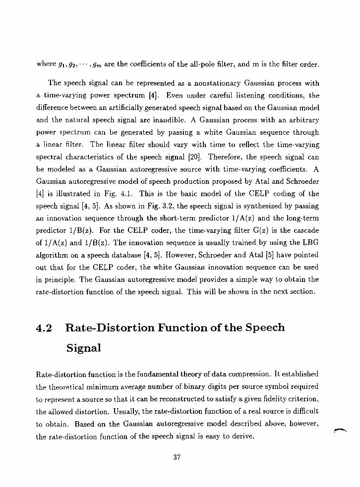
where gl, gz, - - , g, are the coefficients of the all-pole filter, and m is the filter order.
The speech signal can be represented as a nonstationary Gaussian process with
a time-varying power spectrum [4]. Even under careful listening conditions, the
difference between an artificially generated speech signal based on the Gaussian model
and the natural speech signal are inaudible. A Gaussian process with an arbitrary
power spectrum can be generated by passing a white Gaussian sequence through
a linear filter. The linear filter should vary with time to reflect the time-varying
spectral characteristics of the speech signal [20]. Therefore, the speech signal can
be modeled as a Gaussian autoregressive source with time-varying coefficients. A
Gaussian autoregressive model of speech production proposed by Atal and Schroeder
[4] is illustrated in Fig. 4.1. This is the basic model of the CELP coding of the
speech signal [4, 51. As shown in Fig. 3.2, the speech signal is synthesized by passing
an innovation sequence through the short-term predictor l/A(z) and the long-term
predictor l/B(z). For the CELP coder, the time-varying filter G(z) is the cascade
of l/A(z) and l/B(z). The innovation sequence is usually trained by using the LBG
algorithm on a speech database [4,5]. However, Schroeder and Atal [5] have pointed
out that for the CELP coder, the white Gaussian innovation sequence can be used
in principle. The Gaussian autoregressive model provides a simple way to obtain the
rate-distortion function of the speech signal. This will be shown in the next section.
4.2 Rate-Distortion Function of the Speech
Signal
Rate-distortion function is the fundamental theory of data compression. It established
the theoretical minimum average number of binary digits per source symbol required
to represent a source so that it can be reconstructed to satisfy a given fidelity criterion,
the allowed distortion. Usually, the rate-distortion function of a real source is difficult
to obtain. Based on the Gaussian autoregressive model described above, however, )rq r -
the rate-distortion function of the speech signal is easy to derive.

Figure 4.1: Speech source model
White Gaussian Synthetic Speech
Let's consider first the rate-distortion function of a stationary Gaussian autore-
gressive source. The mean squared error (MSE) rate-distortion is used here due to
its mathematical simplicity. Berger [52] has shown that for the mth-order stationary
Gaussian autoregressive source {s,} described in the previous section, the MSE rate-
distortion function of the source {s,} with a power density function S(w) is given
parametrically by 1 =
DO = g L, min[e, S ( w ) l h , (4.3)
and
* Innovation
1 " 1 S ( 4 R(De) = - J max[O, - log -I&,
2~ -r 2 6
Time-varying Linear Filter 1/G(d
where 8 is a parameter and
As stated previously, the speech signal can be modeled as a locally stationary or
quasi-stationary Gaussian autoregressive process in a short time duration. Thus the
above results are valid for a short segment of speech signal, typically speaking, a 9

201ns segment of speech sig~ial. For the VQCELP coder.
where A(z) and B(z) are expressed in Eq.(3.5) and Eq.(3.6).
By applying Eq.(3.5) and Eq.(3.6) to Eq.(4.6) and Eq.(4.i) , we find the estimate
of the speech signal spectrum in the ith frame as follows
where ail, ai2,. . . , ajlo are the coefficients of the short term predictor, G; is the esci-
tation gain, bio is the pitch gain, and d; is the pitch period in the ith frame. Using
Eq.(4.3) and Eq.(4.4), we can find the rate-distortion function of the speech signal
frame by frame.
4.3 Cutoff Rate for the AWGN Channel and
the Rayleigh Fading Channel with the BPSK
rnodulat ion
The cutoff rate & is a parameter similar to the channel capacity. It is defined as a
limit in the data rate of a channel coding system [24, 541. In particular, & is defined
where P, is the average error probability over all possible coding systems, k is the
number of modulation symbols in each codeword, and R si the actual data rate. The
above equation says that as long as the data rake R is less than &, P, can be made
arbitrarily small by increasing k. As mentioned in Chapter 2. the BPSIi modulation
is co~~sidered in this study. The culoll rale Ro for l l ~ e AWGN c h a ~ ~ n e l wil l1 Ll~e BPSIi
modulation is given by [24, 5-11

-5 0 5 10 15 20 25 35 40
0mme1 Siqal to N o w Ratio E m (&I
Figure 4.2: Cutoff Rate of the AWGN channel versus E,/N,
where E,/No is the channel signal to noise ratio.
For an interleaved Rayleigh fading channel with the BPSK modulation, the cutoff
rate & is given by [55, 561
where again E,/No is the channel signal to noise ratio. The cutoff rate & for the
AWGN channel and the Rayleigh fading channel versus the channel signal to noise
ratio, denoted by E,/No in decibels, is illustrated in Fig. 4.2 and Fig. 4.3. As
seen in the two figures, the cutoff rate increases with the E,/N, in both the AWGN
channel and the Rayleigh fading channel. Since the BPSK modulation is used, the
maximum cutoff rate is 1 bit/symbol in the both channels. Notice that the cutoff
rate in the AWGN channel is higher than that in the Rayleigh fading channel for
the same E,/No. When E,/No = 6 dB, for example, & = 0.973 bit/symbol in the
AWGN channel while & = 0.736 bit/symbol in the Rayleigh channel.
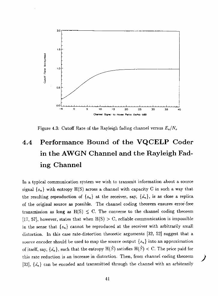
Figure 4.3: Cutoff Rate of the Rayleigh fading channel versus E,/N,
4.4 Performance Bound of the VQCELP Coder
in the AWGN Channel and the Rayleigh Fad-
ing Channel
In a typical communication system we wish to transmit information about a source
signal {s,) with entropy H(S) across a channel with capacity C in such a way that
the resulting reproduction of {s,) at the receiver, say, {&), is as close a replica
of the original source as possible. The channel coding theorem ensures error-free
transmission as long as H(S) 5 C. The converse to the channel coding theorem
[17, 571, however, states that when H(S) > C, reliable communication is impossible
in the sense that {s,) cannot be reproduced a t the receiver with arbitrarily small
distortion. In this case rate-distortion theoretic arguments [32, 521 suggest that a
source encoder should be used to map the source output {s,) into an approximation
of itself, say, {&), such that the entropy H(S) satisfies H(S) < C. The price paid for
this rate reduction is an increase in distortion. Then, from channel coding theorem
[32], (5,) can be encoded and transmitted through the channel with an arbitrarily 1

small distortion, i.e., the only distortion between {sn) and the reconstructed sequence
in the receiver {&) is that produced by the source encoder. Thus the best source
encoder is the one that maps {s,) into is;), satisfying H(&)<c, in such a way that
1%) is as good an approximation of {sn) as possible.
The above discussion is summarized in the information-transmission theorem [19].
This theorem states that the output sequence of a discrete source with the rate
distortion function R(D) can be reproduced with distortion a t most D if
R(D) c C (4.12)
where C is the capacity of a discrete channel. The channel capacity C is the maximum
rate at which information can be reliably transmitted through the channel. There
is a large gap between the performance of practical coding systems and the channel
capacity [25]. Because the cutoff rate & presents a more realistic bound on a coding
system's performance than the channel capacity, the cutoff rate is used to derive
the performance bound of the VQCELP in noisy channels. Following the technique
described by Goblick [53] and Modestino [34], the distortion D can be obtained by
equating the rate-distortion function to the cutoff rate &. In Section 4.2, we derived
the rate-distortion function of the speech signal. In Section 4.3, the cutoff rate for the
AWGN channel and the Rayleigh fading channel is provided. If we let R(D) = &, then D is the smallest distortion which can be attained in theory. Note that R(D)
= & means that the source coding rate is matched to the channel cutoff rate. Since
the speech signal is quasi-stationary, we can only solve for the distortion D frame by
frame. We are aiming for a performance bound in terms of the SSNR between the
original speech and the reconstructed speech.
According to the definition of the SSNR in Section 3.2, 1 A-
S S N R = - x SNR; (4.13) Ii- ;=I
where I i is the number of frames and SNR; is the signal to noise ratio in a frame.
As defined in Section 3.2, SNR; is 2
SNR; = 10loglo C?=n S,
C:=I(sn - i n ) *

where L is the number of samples in a frame.
Under the mean squared fidelity criterion, the distortion D; in the ith frame is
defined as
Let's define the average speech signal energy in a frame as
Therefore,
As discussed above, D is the minimum distortion when we set R(D) = &. According
to Eq.(4.17) and Eq.(4.13), the corresponding SSNR is the maximum value. This
SSNR is referred as to the performance bound of the VQCELP coder on the AWGN
channel or the Rayleigh fading channel.
For each frame, let R(D;) = & and solve for 0 in Eq.(4.4). Substituting the 0
into Eq.(4.3), we find D;. D; can not be found in a close form, but it can be solved
by an iterative procedure [19]. According to Eq.(4.16), the signal energy ui, in a
frame is easily computed. Substituting D; and 1.7; into Eq.(4.17) yields the SNR; in
the ith frame. The performance bound in terms of the SSNR can be found by use of
Eq.(4.13) after the SNR; for every frame of a speech database has been calculated.
As shown in Eq.(4.10) and Eq.(4.11), the cutoff rate & increases with the channel
signal to noise ratio E5/No. Finally, we can obtain the SSNR value as a function of
Es/No on the AWGN channel and the Rayleigh fading channel.
We are concerned with the performance bound of a combined VQCELP and PC
coder at the given transmission rate (6.4 kbits/s) here. For this case, the SSNR
performance as a. function of Es/No for the AWGN channel and the Rayleigh fading
channel is depicted in Fig. 4.4 and Fig. 4.5. At w N 0 = 2.8 dB, for example, the
channel cutoff rate & equals to 0.8. This means that 80 percent of the total rate of
6.4 kbits/s should be used for source coding and 20 percent of the total rate should
be used for channel coding. That is, the source coder should operate at the bit rate of
5.12 kbits/s and the channel coder will use up 1.28 kbitsls. Since the speech signal is
sampled a t the rate of 8 kHz (8,000 samples/s), the source information rate is 5.1218
= 0.64 bitlsample for the transmission rate of 6.4 kbitsls and E,/N, = 2.5 dB. Let
R(Ds) = 0.64 in Eq.(4.4). By using equations (4.3) - (4.17), the SSNR is calculated
to be 20.08 dB. Similarly, the performance bound shown in Fig. 4.5 for the Rayleigh
fading channel is determined in the same way as above for the AWGN channel.
In summary, we used the channel cutoff rate to calculate the performance bound
of the VQCELP coder in the AWGN channel and the interleaved Rayleigh fading
channel. We assumed that the speech signal is an autoregressive source. Also, the
channel cutoff rate is a limit in the data rate of a channel coding system. Thus, the
performance bound obtained above is an upper bound on the performance of practical
combined source and channel coding systems. However, it provides a reference for
practical systems and a guidance for system design.

Figure 4.4: The SSNR bound versus the channel E./N,
on the AWGN channel

Figure 4.5: The SSNR bound versus the channel E,/N,
on the Rayleigh fading channel

Chapter 5
Combined Source and Channel
Coding
In the previous chapter, we obtained the performance bound of the VQCELP coder
in the AWGN channel and the Rayleigh fading channel. This performance is theoret-
ically achievable because the channel cutoff rate is a limit in data rate of a channel
coding system. This chapter will discuss the design of a practical combined source
and channel coding system. Section 5.1 describes some observed characteristics of the
VQCELP coder on noisy channels and the motivations behind this combined source
and channel coding research. The evaluation of the bit error sensitivities is discussed
in Section 5.2. A combined source and channel coding configuration that exploits the
different bit sensitivities is introduced in Section 5.3. Punctured Convolutional (PC)
coding is described in Section 5.4. Under the criterion of the SSNR, both the full
search method and a partial search algorithm for finding the optimal channel code
rate allocation are discussed in Section 5.5.

5.1 Observations and Motivations
The CELP coding can potentially provide high quality speech at very low bit rates.
Recently there are considerable interests in the application of CELP coders to mobile
radio communications. As discussed in Chapter 3, the CELP coder produces good
quality speech a t bit rates as low as 4.S kbits/s in the absence of channel errors. In
the presense of channel errors, however, the reconstructed speech quality degrades
dramatically. Fig. 5.1 illustrates the performance of the 6.4 kbits/s VQCELP coder
shown in Table 3.1 on the AWGN channel.
We can see that the performance of the VQCELP coder degrades rapidly when
Es/No gets lower than 6.8 dB. Note that E,/No = 6.S dB is equivalent to a BER of
lov3 when coherent BPSK demodulation is used. For mobile radio applications, a
BER of loA3 is not uncommon. The goal of this work is to transmit good quality
speech when the BER is as high as The performance bound calculated in
the previous chapter is included in Fig. 5.1. It is observed that the performance
of the 6.4 kbits/s VQCELP coder diverges from the performance bound when the
BER gets higher than We also found that some output bits of the VQCELP
coder are very sensitive to channel errors, while the other bits are not. It should be
pointed out that a bit is sensitive if a transmission error in that bit causes a large
degradation in speech quality. In contrast, errors in the insensitive bits do not cause
much degradation in speech quality. Experimental results show that the quality of the
reconstructed speech improves significantly if the most sensitive bits are protected by
FEC codes. Since FEC codes introduce redundancy, the total transmission bit rate
increases. To avoid increasing the total transmission rate, we can reduce the source
(speech) coding rate and allocate the remaining rate to channel coding. We found
that this would substantially improve the performance of the original VQCELP coder
when the channel signal to noise ratio E,/N, gets lower than 6.8 dB. For example,
at the total transmission rate of 6.4 kbits/s, we can allocate 4.8 kbits/s to source
coding and 1.6 kbits/s to channel coding. Suppose that a rate 112 code is used to
protect the 32 most sensitive bits of a 96 bit speech frame. The simulation result for

0' . VQCELP eodar without chmmd eodmg 9 I 0 VQCELP codw with chamd ooding
- 10 -6 - 2 2 6 10 1 4 18 2 2 2 6 3 0
Channel EsINo (dB)
Figure 5.1: Performance of a 6.4 kbits/s VQCELP coder in the AWGN clmnnel

this experimental scheme is also included in Fig. 5.1. It is illustrated that there is
approximately a 5 dB improvement over the 6.4 kbits/s VQCELP Coder when Es/No
= 4.3 dB. Note that Es/No = 4.3 dB is equivalent to a BER of when coherent
BPSK demodulation is used. More simulation results will be discussed in Chapter 6.
5.2 Evaluation of Bit Error Sensitivity
As explained in Chapter 3, the speech signal is analyzed frame by frame and rep-
resented by the LPC coefficients, the pitch period, the pitch gain, the excitation
gain and the excitation codeword. These parameters are quantized using different
codebooks, and the indices of the chosen codewords are represented by the natu-
ral binary code (NBC). Since the NBC representation of codebook indices lends the
source coders to having unequal bit error sensitivities, we should employ unequal
error protection to protect the different bits from transmission errors.
As the decoder stores a replica of the codebook, the received index determines
uniquely the correct reproduction codeword on a noiseless channel. However, when
channel errors occur, the received indices will differ from the transmitted indices, and
the reproduction codeword will differ from the codeword selected at the encoder. For
a low bit rate codec, transmission errors can cause the speech signal to have severe
distortion in noisy environments. The distortion in the reconstructed speech signal
varies depending on the locations of erroneous bits in a speech frame.
The speech signal is analyzed and synthesized frame by frame in the CELP coder.
An effective procedure for evaluating the bit error sensitivity is to perturb system-
atically bits in the output bit stream, and measure the effect on the SSNR of the
reconstructed speech [12, 151. Suppose there are N, bits in each frame time. We in-
troduce a single error to a specific bit in every frame and measure the SSNR between
the original speech and the reconstructed speech. The bit error sensitivity for each
of the N, bits is evaluated by using 12 speech sentences spoken by 3 males and 3
females.

As an example, we show the bit error sensitivity of a 4.8 kbps VQCELP coder
in Fig. 5.2. The 4.8 kbps VQCELP coder is given in Table 3.2. In Fig. 5.2, along
x axis is the bit number. Along y axis is the resulting averaged SSNR value of the
reconstructed speech. More sensitive bits have lower SSNR values. There are 96
bits in a frame time of 20 ms for the 4.8 kbits/s coder. The correspondence between
the bit number and the coded parameters is included in the figure. We noticed that
the bits representing the excitation gains, the pitch gains and the pitch periods are
more sensitive than the bits representing the LPC coefficients and the excitation
codewords. The lowest value of the bit sensitivities is -40.2 dB, while the highest
value is 8.9 dB. There is approximately a 50 dB dynamic range of bit error sensitivity
among different bits.
The above bit error sensitivity is examined under the condition that a single
bit error occurs in a frame. For the same BER, this sensitivity would be slightly
different from the sensitivity when multiple bit errors occur because there exist some
correlations among the distortions caused by the different bit errors. Accurate bit
error sensitivities can be evaluated by lengthy simulations. However, the bit error
sensitivities evaluated above are adequate to inform us the degree of significance of
the different bits. Our informal listening tests show that the subjective perception
agrees with the evaluated bit sensitivities.
5.3 Combined Source and Channel Coding
Configuration
In the previous section, it was shown that the output bits of the source codes have
a large dynamic range of bit error semi tivity. The more sensitive the bits, the more
error protection they need to receive. This section is to discuss a combined source a.nd
channel coding configuration which will take into account the bit error sensitivity.
To reduce the distortion in speech signals caused by transmission errors, FEC
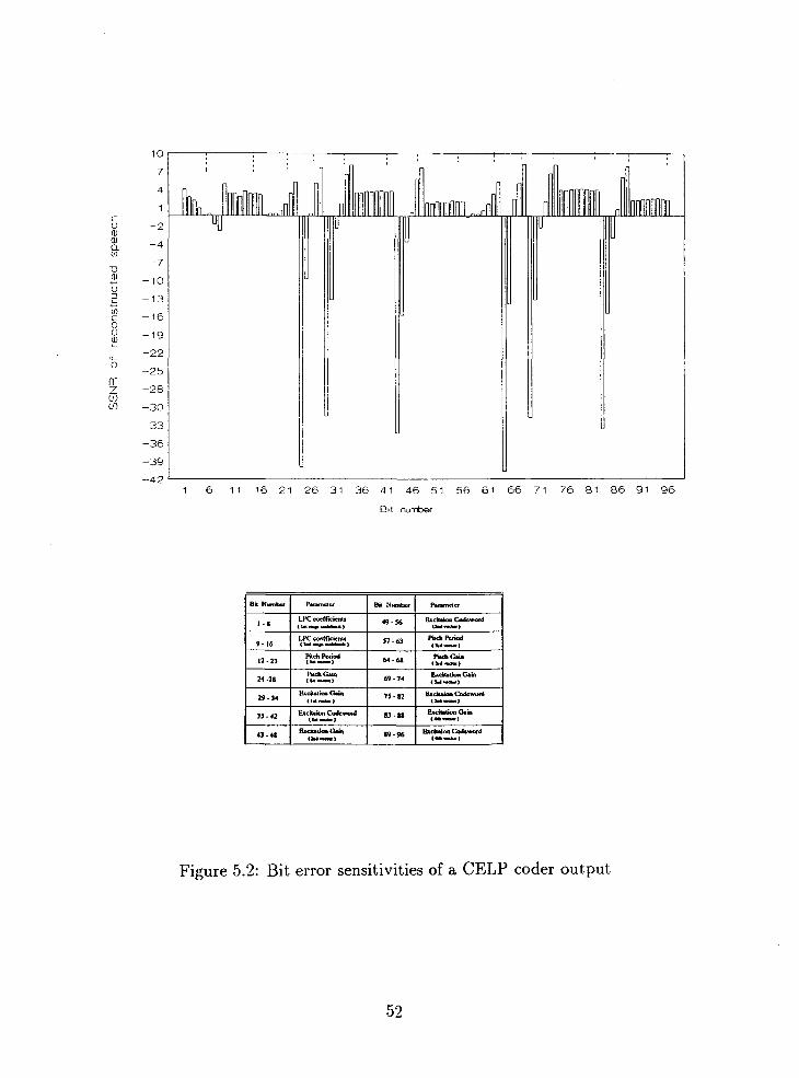
Figure 5.2: Bit error sensitivities of a CELP coder output
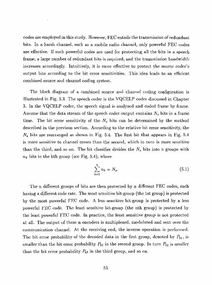
codes are employed in this study. However, FEC entails the transmission of redundant
bits. In a harsh channel, such as a mobile radio channel, only powerful FEC codes
are effective. If such powerful codes are used for protecting all the bits in a speech
frame, a large number of redundant bits is required, and the transmission bandwidth
increases accordingly. Intuitively, it is more effective to protect the source coder's
output bits according to the bit error sensitivities. This idea leads to an efficient
combined source and channel coding system.
The block diagram of a combined source and channel coding configuration is
illustrated in Fig. 5.3. The speech coder is the VQCELP coder discussed in Chapter
3. In the VQCELP coder, the speech signal is analyzed and coded frame by frame.
Assume that the data stream of the speech coder output contains N, bits in a frame
time. The bit error sensitivity of the N, bits can be determined by the method
described in the previous section. According to the relative bit error sensitivity, the
N, bits are rearranged as shown in Fig. 5.4. The first bit that appears in Fig. 5.4
is more sensitive to channel errors than the second, which in turn is more sensitive
than the third, and so on. The bit classifier divides the N, bits into n groups with
n k bits in the kth group (see Fig. 5.4), where
The n different groups of bits are then protected by n different FEC codes, each
having a different code rate. The most sensitive bit-group (the 1st group) is protected
by the most powerful FEC code. A less sensitive bit-group is protected by a less
powerful FEC code. The least sensitive bit-group (the nth group) is protected by
the least powerful FEC code. In practice, the least sensitive group is not protected
at all. The output of these n encoders is multiplexed, modulated and sent over the
communication channel. At the receiving end, the inverse operation is performed.
The bit error probability of the decoded data in the first group, denoted by Pbl is
smaller than the bit error probability Pb2 in the second group. In turn Pb2 is smaller
than the bit error probability Pb3 in the third group, and so on.

Speech Multi-
plexer Modulator Coder
7 Channel
Speech
Decoder
tILOI c o d o n coda 1
Bit Merger
Demulti- plexer
Figure 5.3: Combined source and channel coding configuration

Probability of bit error P b l < P b 2 <
Figure 5.4: Information bits grouped according to their relative sensitivities
For the combined speech and channel coding configuration, it seems that n channel
codecs are needed and the system complexity increases accordingly. To circumvent
this problem, we use punctured convolutional coding in this study. As we are go-
ing to demonstrate, punctured convolutional coding is capable of providing different
levels of error protection using the same codec. As a result, the complexity of the
combined system does not increase. In addition, punctured convolutional codes can
achieve a relatively large decoding gain by using the Viterbi decoding algorithm with
soft decision and channel state information [58]. The definition and the features of
punctured convolutional codes will be discussed in the next section.
Suppose that the total transmission rate R for source and channel coding is fixed.
If the source coding rate is R,, this implies that the channel coding rate R, is Rc =
RIR,. In other words, suppose that the total N bits can be used to represent each
speech frame, if speech coding uses up N, bits, then the number of bits available for
channel coding is Nc = N - N,. As discussed above, the N, bits for source coding have
different sensitivities to channel errors. They are divided into n groups and protected
by n different FEC codes according to their sensitivities. The issue of dividing the
Nc bits among the n FEC codes is an optimization problem that will be addressed in
Section 5.5.

5.4 Punctured Convolutional Codes
5.4.1 Introduction
In recent years convolutional coding with Viterbi decoding has become one of the
most widely used forward error correction techniques. This is due to both the sim-
plicity of implementation and the relatively large coding gains that can be achieved.
The achievement of such coding gains results from the ease with which this algorithm
can utilize demodulator soft decisions and thereby provide approximately 2 dB more
gain than the corresponding hard decision decoder [58]. The design of an error correc-
tion coding system usually consists of selecting a fixed code with a certain code rate
and correction capability matched to the protection requirement of all the data and
adapted to the average or worst channel conditions 1601. For the case discussed in the
previous sections, however, different levels of error protection are expected because
the data to be transmitted have different error sensitivities. For practical implemen-
tations, we would like to use one encoder and one decoder to perform different levels
of error protection. Based on the concept of punctured convolutional coding, Yasuda
e t al. [59] and Hagenauer [60] have proposed elegant techniques for providing differ-
ent levels of error protection by puncturing a rate l / n code. This section describes
how to generate a family of punctured codes from a rate l / n convolutional code.
5.4.2 Convolutional Codes
In Chapter 2, we introduced the conce :pt of convolutional codes. Our discussion of
convolutional code structure uses the notation proposed by Forney [61]. The code
constraint length is defined to be the number of memory elements, denoted by v. A
code is represented by its generator matrix G(D). The element in the jth row and ith
column of G(D),
G;(D) = + g i j ~ + - . - + g L j ~ m , (5 .2 )

Output
r
symbol 1
Input bll b12 b13 b14
b21 b22 bu b24
Figure 5.5: A rate 112 convolutional encoder with a constraint length of 2
relates the ith output sequence to the jth input sequence. The term D is an abstract
quantity, representing a delay of one bit.
An example of a rate 112 convolutional encoder is illustrated in Fig. 5.5, where k
= 1, n = 2, and v = 2. Information symbols are shifted in from the left, and for each
information symbol the outputs of the modulo-2 adders provide two channel symbols.
The generator matrix of this code is
5.4.3 Punctured Convolutional Codes
Punctured convolutional codes were first introduced by Cain et al. [62] for the purpose
of reducing the decoding complexity of high rate convolutional codes. They obtained
codes of rate 213 and 314 by puncturing rate 112 codes. These punctured codes were
almost as good as the best known convolutional codes at the same rates. Based on
the concept of punctured codes, Yasuda et al. [59] found a family of (n-l)/n codes

by puncturing rate 112 codes for n up to 14 [59]. This subsection describes how to
generate a family of punctured convolutional codes using the basic rate l / n code
generator.
Fig. 5.6 shows the basic procedure for constructing a high rate punctured code
from a rate 1 /n convolutional code. The original 1 /n convolutional code in Fig. 5.6(a)
is usually called the mother code. A mother code of rate l / n and a constraint length
v has a generator matrix G(D) of the form
Each punctured code is specified by an puncturing rule as well as a puncturing period.
Fig. 5.6(b) shows a block of original coded data of the mother code in a punctured
period (P intervals), arranged in a matrix of size n x P. We can delete certain bits, say
m bits, among the nP bits according to a puncturing map. As shown in Fig. 5.6(c),
a puncturing map can be represented by a matrix
where aij ~ ( 0 , 1). a;$ = 0 means puncturing, and a ; j = 1 means transmitting. As
shown in Fig. 5.6(d), we obtain a punctured code with a rate
Since the value of m can be 0, . --, (n-1)P-1, we can obtain a family of punctured
codes with rates R, = l /n, - . -, P/(P+l).
Table 5.1 shows an example of punctured convolutional codes. These punctured
codes are obtained by puncturing the coded bits from the rate 112 code shown in
Fig 5.5. The puncturing period P is 4. We denote the binary code symbols by blj
and b2j. The first row shows the code symbols of the rate 112 mother code in a

original
data for a mother code data
original coded data )I- bn,l bnz -- -- - -- -- -- b e bn~+l -----
( x - - - deleted bit )
bl,i x ------- ( d ) ( punctured b IS .,.
bn.1 bn.2 ------- x
Fig. 5.6 Basic procedure for constructing punctured codes
from a rate l/n convolutional code
bl.~+l ----- ...
b n ~ + l -----

Table 5.1: Examples of punctured convolutional codes
( punctured period P = 4 )
original coded bll bn bl3 b14
data (ln code) b21 bez b23 b24
x: deleted symbols
punctured code rate 416 415 4r/ 418

puncturing period P of 4 intervals. The second row gives four different puncturing
maps a(i), i=l to 4. A "0" in the puncturing maps means that the corresponding
code symbol is not to be transmitted. A "1" means that the corresponding code
symbol is to be transmitted. The third row shows the resulting punctured codes.
For the puncturing map a ( l ) , b22, b237 and b14 are punctured, and only bll,b21, b12,
bI3, and b24 are transmitted. The resulting code rate is 415 (recall that there are 4
information bits in a puncturing period). For the puncturing maps a(2), a(3), and
a(4), we obain punctured codes of rates 416, 417, and 418.
There is no constructive method known for determining the generator G(D) of the
mother code and the puncturing maps for punctured convolutional codes. Good punc-
tured convolutional codes are basically found by searching over all possible mother
codes and puncturing maps (under some restrictions), see details in [59, 601.
5.4.4 Performance of Punctured Convolutional Codes in
the Gaussian channel and the Rayleigh Fading Chan-
nel
It is well known that the Viterbi Algorithm (VA) is preferred for decoding convolu-
tional codes. This is due to its features described as follows:
it is a maximum likelihood decoding algorithm for convolutional codes;
it is relatively easy to implement for codes with small constraint lengths; and
it can utilize demodulator soft decisions and thereby provide approximately 2
dB more gain than the corresponding hard decision decoder for AWGN channels
and 2 - 6 dB more gain in Rayleigh fading channels [5S].
Cain et. al. [62] and Yasuda e t . al. [59] have shown that with a slight modification,
the VA can be employed for decoding punctured convolutional codes in the same

manner as it is used for decoding the rate l / n convolutional codes. The only modi-
fication required is to assign a metric of zero to each of the deleted bits. This can be
done by equipping the Viterbi decoder with a copy of the puncturing rule a. Since
puncturing is done periodically, this implies a;j+p = a;j. An explicit expression for
the decoding metric can be obtained from the a;j7s as follows. Assume that the BPSK
is used in this study. As defined in Section 2.3, each coded symbol s ;k is treated as a
complex number (f A, 0), where A is the signal amplitude. On the AWGN channel,
the received signal rk corresponding to the symbol s;k is
where the nk7s are the complex Gaussian random variables with a variance a: =
N0/2, which is also the Gaussian bandpass noise power spectral density. For the full
soft decision, the unquantized values rk's are passed to the Viterbi decoder. Suppose
that the encoded sequence is s = (s;l, s;2, - - -). The VA decoder will compute the
metrics
and finds the maximum likelihood sequence s = (ii17 iii2, - - - ) having the smallest
metric.
In the Rayleigh fading channel, the received signal r k corresponding to the symbol
s;k is
l'k = 9kSik + nk
where the gk7s are zero mean, complex, Gaussian variables with a variance of a," = 1,
and the nk7s are again Gaussian random variables with a variance a: = N0/2. Note
that the gk7s physically represent the channel fading process and are not necessarily
independent. We assume that interleaving is used to de-correlate the gk's so that the
gk7s can be considered as independent variables. We also assume that ideal Channel
State Tnforma.t,ion (CST) i s a.va.ila.ble, that is, t,he receiver has perfect knowledge of the
gk7s. Under the assumptions of ideal interleaving and perfect CSI, the VA decoder
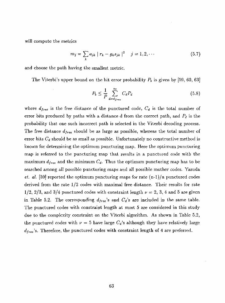
will compute the metrics
and choose the path having the smallest metric.
The Viterbi7s upper bound on the bit error probability Pb is given by [59, 60, 631
where dj,,, is the free distance of the punctured code, Cd is the total number of
error bits produced by paths with a distance d from the correct path, and Pd is the
probability that one such incorrect path is selected in the Viterbi decoding process.
The free distance dj,,, should be as large as possible, whereas the total number of
error bits Cd should be as small as possible. Unfortunately no constructive method is
known for determining the optimum puncturing map. Here the optimum puncturing
map is referred to the puncturing map that results in a punctured code with the
maximum dl,,, and the minimum Cd. Thus the optimum puncturing map has to be
searched among all possible puncturing maps and all possible mother codes. Yasuda
e t . al. [59] reported the optimum puncturing maps for rate (n-l)/n punctured codes
derived from the rate 112 codes with maximal free distance. Their results for rate
112, 213, and 314 punctured codes with constraint length v = 2, 3, 4 and 5 are given
in Table 5.2. The corresponding dfree7s and Cd's are included in the same table.
The punctured codes with constraint length at most 5 are considered in this study
due to the complexity constraint on the Viterbi algorithm. As shown in Table 5.2,
the punctured codes with v = 5 have large Cd's although they have relatively large
dj,,,'s. Therefore, the punctured codes with constraint length of 4 are preferred.

Table 5.2 (a) Map of deleting bits for punctured codes
derived from 112 codes w i t h = 2;- ,5
(1 : transmitting. 0: deleting )
V ; Constraint length defined by Forney [ 52 ] ( * ): Generator polynomial (octal notation ) of original
1/2 code with maximal free distance [ 53 ]
Table 5.2 (b) d h and Cd for punctured codes listed in Table 5.2 (a)

Optimal Code Rate Allocation
The objective of this section is to discuss the issue of finding the optimal code rate
allocation mentioned at the end of Section 5.3. We will describe the full search
method and a partial search method for obtaining the optimal rate allocation using
the SSNR criterion. As indicated in Chapter 3, the SSNR is a performance measure
that is more correlated to the reconstructed speech quality than the SNR.
We are going to use the following example to demonstrate the full search and a
partial search. The total transmission bit rate is 6.4 kbits/s, of which 4.8 kbits/s are
used for source coding and 1.6 kbit/s for channel coding. In other words, there are
128 bits in the frame size of 20 ms, of which 96 bits are allocated for source coding
and 32 bits are redundant bits for error protection. We arrange the 96 bits of the
source coder's output in an order according to the bit sensitivity, as shown in Fig. 5.7.
The leftmost is the most sensitive bit, and the rightmost is the least sensitive bit. A
Rayleigh fading channel with Es/No = 6 dB is considered in this example. Note that
E,/No = 6 dB is equivalent to a BER of when coherent BPSK demodulation is
used. For this channel condition, let's consider four levels of error protection, which
are provided by the rate 112, 21.3, 314 punctured codes with v = 4, and no coding.
The rate 112, 213, 314 punctured codes with v = 4 are listed in Table 5.2. More
levels of error protection and other codes could be considered. However, we found
that no better performance is obtained by replacing the rate 1/2 code by a rate
113 code. This indicates that the rate 112 code is powerful enough for the above
channel condition. Also, it is not necessary to consider higher rate codes since the
BER performance of punctured codes with rates higher than 314 is very close to or
worse than the BER performance of uncoded BPSK at E,/No = 6 dB. Given that
there are four levels of error protection and that there is a total of 32 redundant bits
available, what is the best allocation of the 32 bits (or the code rate allocation) in
the sense that the SSNR of the reconstructed speech is maximized? The answer to
the question clearly can be provided with an exhaustive (full) search for the optimal
rate allocation. It will be shown later that a partial search can provide close to the

Croup I I
Figure 5.7: An example of bit arrangement according to bit error sensitivities for a
6.4 kbit/s combined coder
Probability of bit error
Punctured codes
optimal solution.
5.5.1 Full Search for the Optimal Rate Allocation
P b l <
112
Because the source bits are arranged according to their relative sensitivities, the
possible bit allocation should satisfy the following condition
where Rci is the code rate corresponding to the ith bit. As shown in Fig. 5.7, the
rate allocation is determined by nl, n2, n3 and n4. Clearly, nl, n2, ns and n4 can be
zeros or positive integers, and
P b 2 <
213
Since the data in the 4th group are uncoded, no redundant bits are used in this group.
Under the constraint of 32 redundant bits, we have
P b 3 <
314
p b 4
uncoded

Note that one redundant bit is needed when a rate 112 code is used to protect one
source bit, and a half redundant bit is needed when a rate 213 code is used to protect
one source bit, and so on. Eq.(5.10) and Eq.(5.11) can be rewritten as
with
Equations (5.12) and (5.13) show that n3 and n4 depend on nl and n2. Therefore, the
problem of finding the optimal rate allocation is equivalent to finding the optimum
values for nl and n2. Since n3 2 0, we have the following inequality
According to the inequality (5.14), nl can range from 0 to 32, and n2 can range from
0 to 64. The inequality (5.14) is rewritten as follows
If nl is given, n2 ranges from 0 to 64 - 2nl. Thus the total number of possible
combinations M is
&I= 1 + 2 + - . . + 3 3 =561 (5.16)
According to the combined source and channel coding configuration shown in Fig. 5.3,
the SSNR of the reconstructed speech can be computed for each of the possible rate
allocations. The optimal rate allocation is the one with the largest SSNR. For the
example given in this section, the simulated full search result is shown in Fig. 5.8.
Along x axis is nl, along y axis is n2, and along z axis is the SSNR. The optimal code
allocation is (11, 26), which results in the SSNR of 2.554 dB. It takes about 2 and
half da.y CPU time to do the full search on a Sparc machine. To avoid the full search,
we have devised a partial sea.rch algorithm which is to be discussed in the following
subsection.

SSNR
9 .* the global optimum
n*
a local optimum
Figure 5.8: SSNR versus code rate allocation at E,/N, = 6 dB on an interleaved
Rayleigh fading channel
5.5.2 Partial Search for the Optimal Rate Allocation
Let's write Eq.(5.16) in a general form as
where Nc is the number of redundant bits. In the case where the number of redundant
bits Nc is large, the number of possible rate allocations will increase as N:, rendering
a full search impractical, if not impossible. To avoid the full search, the following
partial search algorithm is proposed. The partial search method uses the rule that if
a "neighbouring" rate allocation has a better performance, the search will continue.
If there are no better "neighbours", the search is completed. As discussed in the
previous subsection, a rate allocation is determined by nl and n2. The neighbors
of a rate allocation (nl, n2) are defined as (nl - 1, n2), (nl + 1, n2), (nl, n2 - 2),
and (nl, n2 + 2). Note that (nl,n2 - 1) and (nl,n2 + 1) are not neighbors of the
rate allocation (nl, n2). This is shown in the inequality (5.15). By definition, this
algorithm obtains a local optimum. Because we do not have any knowledge about
the dependence of the SSNR on nl and 722, the global optimum is not guaranteed.

nl= 6 n2= 32 n 3 130
Fig. 5.9 An example of the partial search
(a) initial rate allocation (b) replace a 1/2 code by a 2J3 code (c) replace a 2.0 code by a l/2 code
112 213 314 uncodcd
I I 2 I ... 16
W '28
n4 =n
...
nl= 5 n 2 = W nj =30
a,= 7 n2= 30 n 3 -30 Ilr '29
Figure 5.9: An example of the partial search
69
112 213 314 uncoded
The partial search algorithm is to be demonstrated using the same example men-
tioned at the beginning of this section. The search procedures are as follows:
... 6 9 7 0 1 1 2 1 ...I 5
(c)
1. Initialize rate allocation. The initial rate allocation can be arbitrary. Because
the source bits are arranged according to their relative sensitivities, the pos-
sible bit allocation should satisfy the condition Eq.(5.9). Let's suppose that
the initial rate allocation is (nl, n2) = (6,32). Using equa.tions Eq.(5.12) a,nd
Eq.(5.13), we have ns = 30 and n4 = 28. This initial rate allocation is depicted
in Fig. 5.9(a). As shown in Fig. 5.9(a), the 6 most sensitive bits (the leftnlost
6 bits) are coded by the rate 112 code, the 7th to 38th bits are coded by the
7 I ... 96 . 38
6 1 7 ) ...
38
314 uncoded
8 1
68 95 39
3 8 3 9 4 0
...
213 1 12
2 1 ... ... 7 37

213 code, the 39th to 68th bits are coded by the 314 code and the 69th to
96th bits are uncoded. According to the combined source and channel coding
configuration shown in Fig. 5.3, reproduce the speech and calculate the SSNR
between the original speech and the reconstructed speech based on this rate
allocation. Note that the SSNR is defined in Section 3.2.
2. (a) Replace rate 112 code by rate 213 from the right to the left (see Fig. 5.9(b)).
Based on the initial allocation in step 1, replace the 1/2 code by the rate
213 code at the 6th bit to get a new bit allocation, that is, the first 5 bits
are coded by the rate 112 code, the 6th to 39th bits by the rate 213 code,
the 40th to 69th bits by the 3/4 code and the other 27 bits are uncoded.
The new rate a.llocation is shown in Fig. 5.9(b). Then reproduce the speech
and compute the SSNR. If the SSNR does not improve, go to step 2(b).
If the SSNR improves, continue the replacement.
(b) Replace rate 213 code by the rate 112 code from the left to the right.
Based on the initial allocation in step 1 (see Fig. 5.9(a)), replace the 213
code by the rate 1/2 at the 7th and 8th bits to get a new bit allocation,
that is, the first 7 bits are coded by the rate 112 code, the 8th to 37th bits
by the 213 code, the 38th to 67th bits by 314 code and the other 29 bits are
uncoded. The new rate allocation is shown in Fig.5.9(c). Then reproduce
the speech and compute the SSNR again. If the SSNR does not improve,
go to step 3. If the SSNR improves, continue the similar replacement.
3. (a) Replace the rate 213 code by the rate 314 from the right to the left. The
replacement is similar to the procedure shown on step 2. Then reproduce
the speech and conlpute the SSNR again based on a new rate allocation.
If the SSNR does not improve, go to step 3(b). If the SSNR improves,
continue the similar replacement.
(b) Replace the rate 3/4 code by the rate 213 from the left to the right. Based
on a new rate allocation, reproduce the speech and compute the SSNR
again. If the SSNR does not improve, go to step 4. If the SSNR improves,
continue the similar replacement.

4. Go to step 2 again. If there is no SSNR improvement after one iteration,
terminate.
Different initial rate allocations may result in different local optima. Because
the partial search algorithm does not guarantee the global optimum, the initial rate
allocation is important in obtaining a good performance. There is no general method
available to determine an initial rate allocation which results in a good performance.
In this study, we chose an initial rate allocation according to the bit error sensitivities
and subjective tests. It is shown in Section 5.2 that the source coder's output bits
have a large dynamic range of bit error sensitivities. An initial rate allocation should
be chosen such that the most sensitive bits are protected by the most powerful codes,
and less sensitive bits are protected by less powerful codes. If the reconstructed
speech does not have loud noise based on this rate allocation, it can be used as the
initial rate allocation for the partial search algorithm. Our experments show that
this way of choosing the initial rate allocation usually results in a good performance.
For the example given at the beginning of this section, the simulated partial search
result is also shown in Fig. 5.5. Based on the initial allocation (17, 30), the partial
search algorithm results in the locally optimal SSNR of 2.148 dB at the rate allocation
(15,24). The local optimum is 0.406 dB lower than the global optimum. It takes only
6 hour CPU time to do the partial search on a Sparc machine. The partial search
algorithm takes much less time than the full search method.
We can summarized these two methods as follows. The full search method always
guarantees to reach the global optimum, but it is an exhaustive and time consuming
search. On the other hand, the partial search method can only reach a local optimum,
but it is much less time consuming. When the number of redundant bits is not very
large, the full search method is preferred. If the number of redundant bits is larger,
say, more than 100, the partial search method will be preferred since the full search
would be impractical.

Chapter 6
Experimental Results
This chapter is to present experimental results on combined source and channel
coding. Firstly, we briefly describe the block diagram of an experimental com-
bined VQCELP and PC coding system. Section 6.2 gives the performance of the
VQCELP coders in noisy channels. The techniques for improving the robustness of
the VQCELP coders are discussed in Section 6.3. Experimental results for the com-
bined VQCELP and Punctured Convolutional (PC) coder in the AWGN channel and
the Rayleigh fading channel are given in Section 6.4 and Section 6.5, respectively.
6.1 Experimental Combined VQCELP and P C
Coding System
The block diagram of the combined VQCELP-PC coder is shown in Fig. 6.1. The
analog speech signal is sampled at a rate of S kHz and then each sample is digitized to
12 bits. The digitized speech signal is the input to the VQCELP coder. The VQCELP
coder compresses the input digitized speech signal into a binary bit stream. This
compressed bit stream will be encoded by different punctured convolutional codes,
depending on the different bit sensitivities. Both the AWGN and the Rayleigh fading

channels described in Chapter 2 are considered in this study. Prior to modulation,
the encoded binary digits will be interleaved by a convolutional interleaver if the
channel is a fading channel. The interleaved bits will be individually modulated
using Binary Phase Shift Keying (BPSK). We assumed that coherent demodulation
and perfect carrier recovery can be achieved at the receiver. The received signal will
be filtered by a matched filter at the receiver. The matched filter output will be
sampled and de-interleaved. Each de-interleaved sample will be fed directly to the
channel decoder which is implemented using the Viterbi algorithm with soft decision
and perfect Channel State Information (CSI). The output of the channel decoder
will be processed by the VQCELP decoder to reconstruct (a distorted version of) the
original analog speech. In this chapter, we will describe and present the results of a
software simulation of the system block diagram shown in Fig. 6.1.
The experimental results to be presented in this thesis are conducted mainly for
a new mobile radio application where the total bit rate of S kbits/s is available [I].
Since 1.5 kbits/s are reserved for system overhead, the remaining 6.5 kbits/s are
available for speech transmission and error protection. In this application, a speech
coder is required to produce good quality speech at a bit error rate as high as
and intelligible speech at a bit error rate of 5-10-2 in the AWGN channel or the
Rayleigh fading channel. We used 6.4 kbits/s for speech transmission and left 0.1
kbits/s for other uses, such as error detection, or future expansion of speech coders.
The expandability of a speech coder is important since very low bit rate coding
technology is still relatively immature. The proposed combined VQCELP-PC coder
at 6.4 kbits/s may be also considered to be an approach to the half-rate (6.5 kbits/s)
VQCELP Coder in Noisy Channels
As discussed in the previous section, the total transmission ra.te is 6.4 kbit,s/s. The
6.4 kbits/s VQCELP coder is discussed in Section 3.5, and the best bit allocation for
this coder is given in Table 3.1. The 6.4 kbits/s VQCELP coder is able to reconstruct
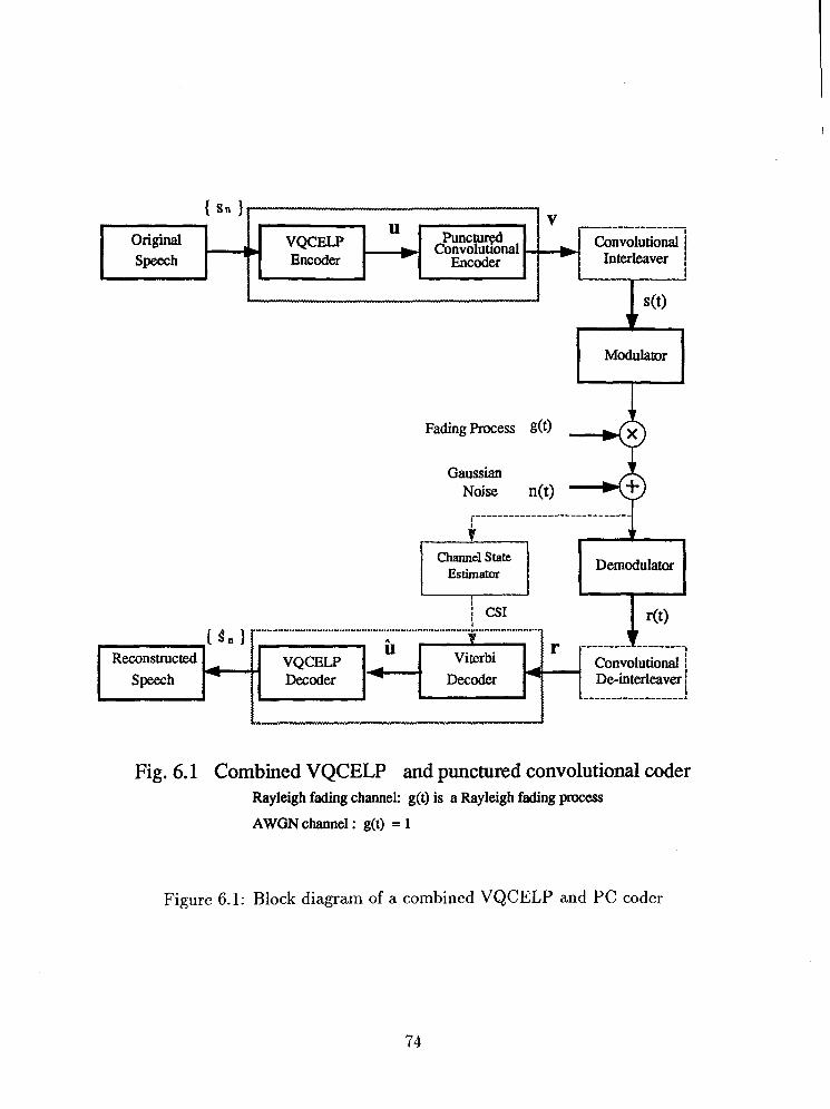
Modulator Lrl Gaussian
Noise n(t)
I
Convolutional / Decoder Decoder De-interleaver j
I ------------------,
Fig. 6.1 Combined VQCELP and punctured convolutional coder Rayleigh fading channel: g(t) is a Rayleigh fading process
AWGN channel : g(t) = 1
Figure 6.1: Block diagram of a combined VQCELP and PC coder

the original speech with a SSNR of 11.17 dB on a clear channel. Informal listening
tests indicate that the speech is of good quality.
Without channel coding, the output data stream from the coder are directly
modulated by BPSK. Assume that coherent detection of BPSK is performed at the
receiver. The performance of the 6.4 kbits/s VQCELP coder in the AWGN channel
is plotted in Fig. 6.2. As a reference, the performance bound for the VQCELP in the
AWGN channel is included in the same figure. The performance of the 6.4 kbits/s
VQCELP coder on the interleaved Rayleigh fading channel is shown in Fig. 6.3.
Here we assume that the interleaving depth and span are large enough that the de-
interleaved symbols experience independent fading. The performance bound for the
VQCELP in the Rayleigh fading channel is also included in Fig. 6.3 as a reference. In
both figures. along the horizontal axis is the signal to noise ratio E,/No per channel
symbol in decibels, where E, is the average received signal energy per symbol and
N0/2 is the power spectral density of the bandpass channel noise. Along the vertical
axis is the SSNR of the reconstructed speech. Note that E,/No = 4.3 dB and E,/No
= 6.S dB are equivalent to a BER of and in the AWGN channel. On
the other hand, for the Rayleigh fading channel, E,/No = 14.5 dB and 24 dB are
equivalent to a BER of and It is observed that the performance of the
6.4 kbits/s VQCELP coder degrades dramatically and diverges from the performance
bound when the E,/N0 gets lower than 6.8 dB (equivalent to a BER of in the
AWGN channel. Fig. 6.3 also shows that the performance of the 6.4 kbits/s VQCELP
coder diverges from the performance bound when the Es/No becomes lower than 24
dB in the Rayleigh fading channel. This phenomenon indicates that the compressed
data from the speech coder need error protection at low E,/No. Since error protection
entails the transmission of redundant bits, the total transmission rate increases. To
avoid increasing the total transmission rate, we can reduce the source (speech) coding
rate and allocate the remaining rate to channel coding. As pointed out in Section 5.3,
this idea leads to our combined source and channel coding system. Clearly in such
a cornbilled system, we must find a good balance in the bit rate assignment between
source and channel coding.

Our objective is to transmit good quality speech a t a BER of and intelligible
speech at a BER as high as 5.10-2. As mentioned above, the BER of lo-' is equivalent
to Es/No = 4.3 dB in the AWGN channel and Es/No = 6 dB in the Rayleigh fading
channel. And the BER of 5.10-2 is equivalent to Es/No = 1.3 dB on the AWGN
channel and Es/No = 6 dB on the Rayleigh fading channel. In this range of Es/No
of interest, experimental results indicate that the assignment of 4.5 kbits/s for source
coding and 1.6 kbits/s for channel coding is a good compromise. The simulation
results on the 6.4 kbits/s combined coder will be presented in the following sections.
6.3 Improvement of the VQCELP Coder's
Robustness
As discussed in Chapter 5, the effect of channel errors can be reduced by error pro-
tection. However, it is also possible to improve the speech coder's robustness to
channel errors without the use of error correction techniques. One such technique is
Pseudo Gray coding [2, 71. We have also used this technique to improve the bit error
sensitivity of the LPC coefficients and the excitation codewords.
For the combined source and channel coding system, the source coding subsystem
is the 4.8 kbits/s VQCELP coder shown in Table 3.2. This coder is able to reconstruct
the original speech a t the SSNR of 9.3 dB. The bit error sensitivity for the 4.8 kbits/s
VQCELP coder, given in terms of the SSNR is plotted in Fig. 6.4. The correspondence
between the bit numbers and parameters is included in the same figure.
From the bit error sensitivities plotted in Fig. 6.4, we see that those parameters
that are vector quantized, like the LPC coefficients and the excitation codewords,
have almost equal bit error sensitivity. This is in contrast to the parameters that
are scalar quantized, like the pitch gains, the pitch periods, and the excitation gains.
These last three parameters have unequal bit error sensitivity.
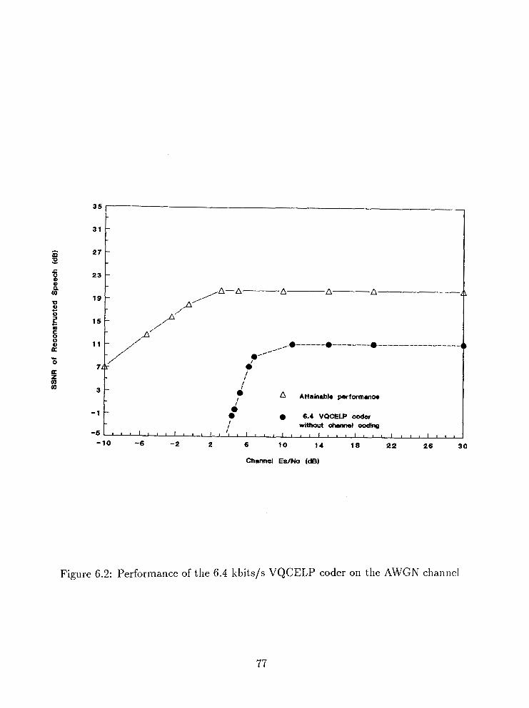
- 10 -6 - 2 2 6 10 14 18 22 26 30
Channel Ea/No (dB)
Figure 6.2: Performance of the 6.4 kbits/s VQCELP coder on the AWGN chmnel

-10 - 3 4 11 18 2 5 32 3 9 46 5 3 6 0
Charnel -/No (dB)
34
3 0
26
22
18
14
Figure 6.3: Performance of the 6.4 kbits/s VQCELP coder on the Rayleigh fading
channel
-
-
- +A--- A ----- A--.A ----- M. A ---------. A ------------------ A ------------------ A ---.--.-----.----
.A-- - ,A=-
- ,A"
1 0 - ,,*' ye 6
4' - /*'*
2
-2
OII the Interleaved Fiaylaigh fadng chamel
-
i A Attairuble Performance
- 6.4 kbitalr VQCaP without 0 chaMlal coding

Before applying error correction codes we managed to improve the robustness of
the coder parameters by using Pseudo-Gray coding. In speech coding systems that
use scalar quantization, each quantization level is assigned a binary codeword. By
choosing an appropriate mapping, such as a Gray code, the average distortion in re-
producing the speech signal due to channel noise can be reduced. Such codes have the
property that code words with small Hamming distances from each other correspond
to scalar quantization levels with small distances apart from each other. Pseudo-Gray
coding is an extension of Gray coding to cover the case of multidimensional signal
vectors.
The improved bit error sensitivity as a result of applying Pseudo-Gray coding
to excitation codewords and LPC coefficients is shown in Fig. 6.5. The bit error
sensitivity of the excitation codewords improves by 1.3 dB in SSNR, on average. For
LPC coefficients, as mentioned above, we used a two stage quantization. By using
Pseudo Gray coding, the bit error sensitivity of the second stage codebook improves
by 1.1 dB in SSNR, but there is only a slight improvement ( approximate 0.2 dB in
SSNR) for the first stage codebook. Note that Pseudo-Gray coding is not applied to
the pitch period, the pitch gain and the excitation gain. Thus it is shown in Fig. 6.5
that the bit error sensitivities for these three parameters are identical before and after
Pseudo-Gray coding.
6.4 Performance of the Combined VQCELP and
PC Coder in the AWGN Channel
The AWGN channel is the most commonly used channel model in the analysis and
simulation of communication systems. We are going to present the performance of
the combined VQCELP-PC coder at 6.4 kbits/s in the AWGN channel in this section.
As discussed in the previous section, 4.8 kbits/s are assigned to source (speech)
coding and 1.6 kbits/s are assigned to channel coding for the combined source and
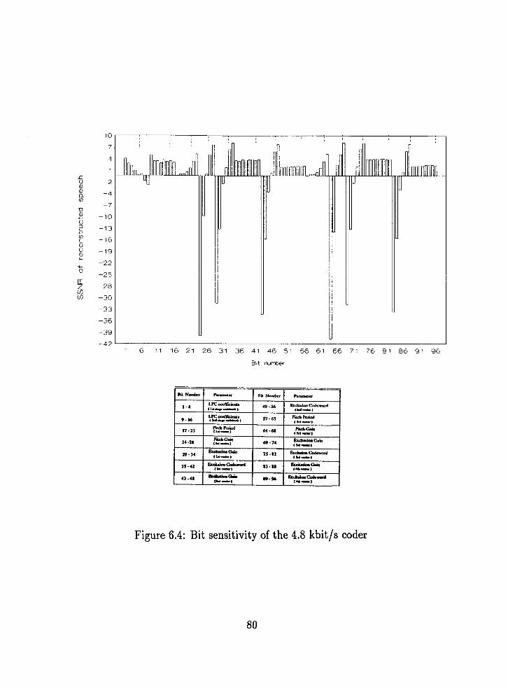
Figure 6.4: Bit sensitivity of the 4.8 kbit/s coder

W m.ilhaU0r.y d i n g 0 With Gray ccding I
Bit Numbcr Panmau Bit Number Pammeer 1
Figure 6.5: Improved bit sensitivity of the 4.5 kbits/s VQCELP coder
17 -23
24 -28
Pit* Period (Id-)
Piteh Gain (la-)
w-68
69 - 74
Pitch Glin (Ld-)
Exatation Gam ( M e )

channel coding system. Recall that the frame time is 20 ms for the VQCELP coder.
Thus, there is a total number of 128 bits in a frame, among which 96 bits are assigned
to source coding and 32 bits are allocated to channel coding. In practice, the worst
case channel condition should be considered in the design of the combined coder.
Since we are concerned with the reconstructed speech quality at a BER of as high
as 5.10-2, Es/No = 1.3 dB is considered as the worst case channel condition. It
is well known that the complexity of the Viterbi decoder grows exponentially with
the constraint length of a convolutional code. We consider punctured codes with
constraint length v < 5 due to the complexity constraint on the Viterbi decoder.
Table 5.2 lists the optimum punctured codes with constraint length v 5 5 (reported by
Yasuda et. al. [59]). For the above worst case channel condition, we have considered
four levels of error protection. They are provided by rate 112, 213, 314 punctured
codes with constraint length of 4, and no coding. The punctured codes with constraint
length 4 listed in Table 5.2 are preferred because they have relatively small Cd and
large df,,,. The puncturing map for these punctured codes is given in Table 6.1. A
Viterbi decoder with soft decision is employed. The decision depth of the Viterbi
decoding is chosen to be 5 times the code constraint length, i-e., 20 intervals. The
simulated error performance of these codes is plotted in Fig. 6.6. More levels of error
protection could be considered. At Es/No = 1.3 dB, however, the BER performance
of the rate 415 punctured codes with constraint length v < 5 is not better than the
BER performance of the uncoded BPSK. It is not necessary to consider punctured
codes at rates higher than 415. Also, we found that no better performance is obtained
by replacing the rate 112 code by a rate 113 code. This indicates that the rate 1/2
code with constraint length 4 is powerful enough for the channel condition being
considered. As such, only these four levels of error protection is considered in this
study. Given the bit error sensitivity in Fig. 6.5 and the four levels of error protection,
the optimal rate allocation is obtained by the full search method proposed in Chapter
5 . Since the number of redundant bits is only 32, the full search method is preferred.
Table (5.2 gives the opli11la1 code rate allocation for Es/No = 1.3 dB in the AWGN
channel. The performance of the combined VQCELP-PC coder versus the channel
Es/No in decibels is illustrated in Fig. 6.7. Along the x axis is the channel signal

Channel EslNo (dB)
Figure 6.6: Error protection capability of rate 112, 2/3, and 3/4 punctured codes on
the AWGN channel

to noise ratio Es/No in decibels. Along the y axis is the SSNR of the reconstructed
speech. The performance of the 6.4 kbits/s VQCELP coder without channel coding
is included in the same figure for comparison. It is noticed that the combined coder
achieves approximately a 10 dB improvement in the SSNR over the VQCELP coder
without channel coding at Es/No = 4.3 dB (equivalent to the BER of On
a clear channel, the combined coder loses 1.S7 dB in the SSNR, compared to the
VQCELP coder without channel coding. This is due to the fact that 1.6 kbits/s has
been assigned to channel coding while it is not necessary to have channel coding on a
clear channel. Informal listening tests indicate that the combined coder significantly
improves the quality of the reconstructed speech at low channel signal to noise ratio.
6.5 Performance of the Combined VQCELP and
PC Coder in the Rayleigh Fading Channel
For mobile radio applications, the channel experiences severe signal-strength attenu-
ation, co-channel and adjacent channel interference, as well as Rayleigh fading. As
mentioned in Section 2.3, mobile radio channels are usually modeled as a Rayleigh
fading channel. We will present in this section the performance of the combined
VQCELP-PC coder in the Rayleigh fading channel. Both infinite interleaving and
finite interleaving are considered in our simulation.
6.5.1 Performance in the Rayleigh Fading Channel with In-
finite Interleaving
The Rayleigh fading channel model is defined in equation (2.10). As described in
Section 2.3, the fading variables gk's are correlated. The correlation depends on the
fading spectrum given in Eq.(2.8). The purpose of the interleaver and de-interleaver
is to de-correlate the fading experienced by the modulated symbols in different inter-

................ @. -*
8
/c-
6 On the AWGN Channel
- - - on a clear c h a m 1
2 . 6.4 kbitt/n VQCELP Coder without channel coding
0 0 combined coder at 6.4 kbitsls
0 2 4 6 8 1 0 12 14 16 18 2 0
Channel EslNo (dB)
Figure 6.7: Performance of the combined coder on the AWGN channel

vals. In this subsection, we assume that infinite interleaving is achieved. By infinite
interleaving, we mean that each de-interleaved symbol is affected independently by
the channel fading process.
The block diagram of the combined VQCELP-PC coder in the Rayleigh fading
channel is shown in Fig. 6.1. For the combined coder operating at 6.4 kbits/s, the
bit rate assignment between source coding and channel coding is 4.8 kbits/s and 1.6
kbits/s. The 4.8 kbits/s VQCELP coder was discussed in Section 3.6 and given in
Table 3.2. Also, the improved bit error sensitivity of the coder is shown in Fig. 6.5.
As discussed in the previous section, the worst case channel condition should be
considered in the design of the combined coder. A BER of 5.10-2 is equivalent to an
E,/N, = 6.0 dB for coherent BPSK demodulation in the interleaved Rayleigh fading
channel. Thus, the E,/N, = 6.0 dB is considered as the worst case. For this worst
case channel, we have considered four levels of error protection, which are provided
by rate 112, 213, 314 punctured codes and no coding. These punctured codes are
listed in Table 6.1. Since the amplitude of the received signal experiences Rayleigh
fading, the following two assumptions are made in the decoding:
1. perfect channel state information (CSI) is available, i.e., the gk's are known at
the receiver,
2. the fading process is slow enough so that gk accurately represents the fading in
the kth symbol interval.
The first assumption is reasonably true in practical systems. For instance, pilot tone
techniques provide good estimation of the fading process gk. The second assumption
is easily justified for mobile radio applications since the fading rate is usually less
than one percent of the symbol rate. A Viterbi decoder which uses soft decision and
perfect CSI is considered in this study. The decision depth of the Viterbi decoding
is chosen to be 20 intervals. The simulated error correction capacity of these codes
on the interleaved Rayleigh fading channel is plotted in Fig. 6.8.
Using the full search proposed in Chapter 5, the optimal rate allocation for the

combined coder at E,/No = 6.0 dB is shown in Table 6.3. The performance of the
combined coder on the interleaved Rayleigh fading channel is plotted in Fig. 6.9, along
with the performance of the VQCELP without channel coding. At E,/No = 14.5 dB
(equivalent of the BER of the combined coder obtains approximately a 12 dB
improvement over the VQCELP coder without channel coding. For the same reason
mentioned in the previous section, on a clear channel, there is a 1.87 dB degradation
for the combined coder, with respect to the performance of the 6.4 kbits/s VQCELP
coder.
6.5.2 Performance in the Rayleigh Fading Channel with
Finite Interleaving
The previous subsection has discussed the performance of the combined VQCELP-PC
coder in the Rayleigh fading channel with infinite interleaving. If interleaving depth
and span are large enough, finite interleaving is almost as good as infinite interleaving.
Theoretically, the interleaving depth is chosen with the same order of magnitude
as the fade duration and the interleaving span is chosen with the same order of
magnitude as the decision depth of the Viterbi decoder. Interleaving introduces an
extra end-to-end delay. In mobile radio systems, long delay is not desirable. As a
result, the interleaving depth and span should be chosen as small as possible. We
use convolutional interleaving instead of block interleaving in this study because the
former only introduces a delay half that of the later.
A Rayleigh fading channel with a maximum Doppler frequency fD=24, 48 and 96

BER of Punctured Codes( 1 /2,2/3,3/4) On Raylelgh Fading Channel
0.0 5.0 10.0 15.0 20.0 25.0 30.0
Channel Es/No (dB)
Figure 6.8: Error correction capacity of rate 112, 213, and 314 punctured codes on
the interleaved Rayleigh fading channel

0 - 6.4 kbits/a VQCELP oodff without channel coding
- 2 - combined coder at 6.4 kbitsls
- 4 ~ I ~ 1 ~ I ~ I ~ I ~ I ~ ~ I I ~ I ~ I ~ I l ~ ' ~ ~ ~ ~ ~ ' ~ ~ ' ~ ~ ~ ~ L
0 2 4 6 8 1 0 12 14 1 6 18 2 0 22 24 2 6 2 8 3 0 3 2 34 3 6 3 8 40
Channel EslNo (dB)
Figure 6.9: Performance of the combined VQ-CELP and PC coder on ideal interleaved
Rayleigh fading channel

Hz was simulated. The Doppler frequency of fD=24, 48 and 96 Hz is equivalent of a
vehicle speed of approximate 25, 50 and 100 km/h in the 800-900 MHz transmission
band. A Viterbi decoder that uses soft decision and channel state information (CSI)
was considered in our simulation. Decoding depth was chosen to be 20 intervals.
Considering that only one frame delay (20ms) is allowed for interleaving, we chose an
interleaving depth of 16 and an interleaving span of 8. Fig. 6.10 shows the simulated
SSNR performance for the combined coder versus the signal to noise ratio Es/No for
the three different Doppler frequencies. The combined coder is based on the rate
allocation shown in Table 6.3. The performance with infinite interleaving is given in
the same figure to show the effect of finite interleaving on the system. It is observed
that the more slowly a vehicle moves, the longer the fading duration and consequently
the poorer performance by the finite interleaver. It is shown that at fD = 48 Hz (or
a vehicle speech of 50 krn/h) and Es/No = 14.5 dB (or a BER of there is only
a 0.8 dB degradation by using finite interleaving.
By summary, we have discussed in this section the effect of the 16x8 convolutional
interleaver on the combined coder's performance. The simulated results given above
show that the finite interleaving only causes slight performance degradation compared
to the ideal (infinite) interleaving. Informal listening tests also indicate that good
quality speech can be obtained with the combined coder at a BER of on the
considered Rayleigh fading channel. We conclude that the proposed combined coder
is a feasible scheme for the mobile radio application where the total bit rate available
is 8 kbits/s, of which 1.5 kbits/s is used for system overhead.

0 2 4 6 8 1 0 12 1 4 1 6 18 2 0 2 2 2 4 2 6 2 8 3 0 3 2 3 4 3 6 3 8 4 0
Channel EslNo (dB)
16
1 4
1 2
1 0
8
6
4
2
0
- 2
Figure 6.10: Performance of the combined VQCELP-PC coder on the Rayleigh fading
channel with finite interleaving
-
-
-
- infinite interleaving
-
-
- On the Rayleigh fading
with finite interleaving ( 16 x 8 1 - : I ,
: / / ; /A 0 Doppler frequency f D - 96 Hz
- Doppler frequency ID = 48 Hz /'i
- I ' I ! A Doppler frequency f D = 24 Hz

Table 6.1: Map for rate 112, 213 and 314 punctured codes
Coding Deleting Puncture
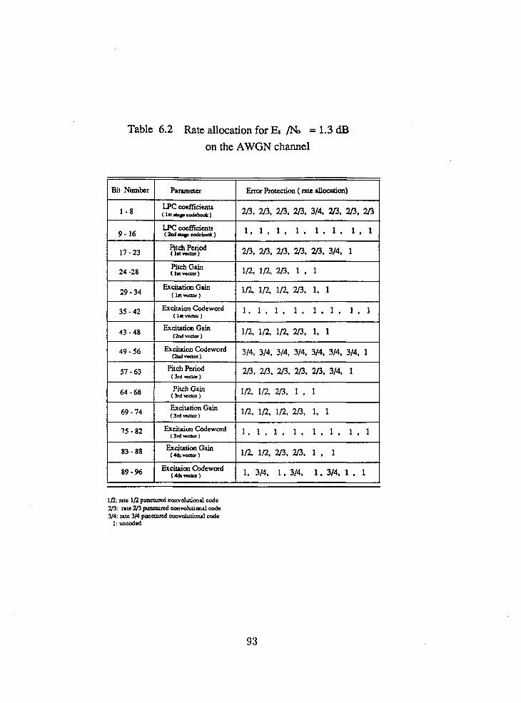
Table 6.2 Rate allocation for Es /No = 1.3 dB
on the AWGN channel
Bit Number P ~ r ~ m w h r Protection ( rate Pllocrtion) 1
9- 16
I7 - 23
24 -28
29 - 34 35-42
1R. rate 1R p u n d convolutiond code 2/3: nrc 223 puncmd convolutirnal code 314: ntc 314 p u n 4 convalutid code
1: unccded
43 - 48 49 - 56
57 - 63
64 - 68
LPC coefficients ( m d p d a y b ~ ~ k )
Pitch Period (ln-)
Pitch Gain (la-1
Exataticm Gain (In-)
ExdtaionCodaword (In-)
l , l , 1 , 1 , 1 . 1 , 1 . 1
20. 2P. 2P. 223. 2/3, 314, 1
1D. ID. 33 . 1 . 1
I n i n i n m, 1, 1
1 , 1 , 1 , 1 , 1 . 1 . 1 . 1
Excitaricm Gain ~M-)
ExcitaiOn (hrd-)
Pitch Period (hd-)
Pitch Gain (3rdvcaor)
l a 1 n 1 n m, 1. 1
314, 314. 314, 314. 314, 314, 314. 1
2 0 , 20 . 2l3, 2P. 2f3. 314. 1
la la m, 1 . 1

Table 6.3 Rate allocation for ES Pb = 6 dB on the interleaved Rayleigh fading channel
Etch Gain 24 -28 (la-)
Pitch Gain ( I (M-1

Chapter 7
Conclusions and Future Studies
The major conclusions are summarized as follows:
1. The CELP coding is a new technique for providing high quality speech at low bit
rates. However, the reconstructed speech quality degrades dramatically when
channel errors occur. In order to improve the reproduced speech quality in noisy
conditions, this thesis introduces the combined source and channel coding of
speech, using VQCELP coding and PC coding.
2. The bit error sensitivity of the VQCELP coder is studied through simulation. It
is found that there exists a large dynamic range of bit error sensitivities among
the different output bits of the VQCELP coder.
3. Based on the information transmission theorem, we derive in this thesis the
performance bound of the combined VQCELP-PC coder in the AWGN channel
and the Rayleigh fading channel. In very noisy conditions, the performance
of the VQCELP coder without channel coding diverges from this performance
bound. This phenomenon indicates t,ha.t. error protection is needed for the
VQCELP coder, and it is possible to improve the reconstructed speech quality
by trading off source coding for channel coding.

4. In the combined VQCELP-PC coder, different levels of error protection are
applied to different bits according to their bit error sensitivities. PC coding is
capable of providing different levels of error protection with the same codec.
Due to the employment of the PC coding technique, the complexity of the
combined coder Goes not increase. To arrive at an efficient combined coder, the
full search method and a partial search method for finding the optimal channel
code rate allocation are proposed.
5. Simulation results show that at a BER of the combined coder can obtain
up to 10 dB improvement in the AWGN channel and 12 dB improvement in
the Rayleigh fading channel, with respect to the VQCELP coder without chan-
nel coding at the same transmission rate. Note that these improvements are
measured in terms of the SSNR of the reconstructed speech. Informal listen-
ing tests indicate that good speech quality can be maintained even when the
channel BER gets as high as
Recommendations for further research include the following:
1. This thesis focuses on the error correction for the combined VQCELP-PC coder.
The combination of error correction and parameter smoothing with error de-
tection would be an interesting topic. By use of error correction codes, the bit
error rate can be reduced significantly. Thus the possibility that one or more
errors are detected in the binary code representing the same parameter in con-
secutive frames would be very small, even under very noisy conditions. In this
case, parameter smoothing would be attractive.
2. The experimental results in Chapter 6 show that on a clear channel, the com-
bined coder has 1.8 dB degradation with respect to the VQCELP coder at
the same rate. The degradation is due to that certain a.mount of bit rate is
assigned to channel coding. The trade-off of source coding against channel cod-
ing in response to the channel condition would avoid this degradation. When
the channel is in a good condition, no bit rate is assigned to chmnel coding.

When the channel gets noisier, more bit rate is assigned to channel coding.
The channel condition may be judged by testing the correlation between LPC
coefficients in two or more consecutive frames at the receiver. There is a high
correlation between LPC coefficients in adjacent frames for the speech signal.
If this correlation is maintained at the receiver, the channel is considered to
be in a good condition. Otherwise the channel is considered to be in a poor
condition.
3. Punctured convolutional codes are employed in this study. Reed-Solomon codes
may be an alternative to punctured convolutional codes to combat burst channel
errors.
4. It is recently reported that the combined modulation and coding can reduce
the probability of bit error without bandwidth expansion and power increase.
The study of combined source coding, channel coding and modulation would
result in more efficient transmission systems.

Bibliography
[l] T . E. Tremain, J . P. Campbell, Jr., V. C. Welch, J. R. Goble and M. A. Kohler,
DoD 4.8 kbps Standard (Proposed Federal Standard 1026 Voice Codel-), IEEE
Workshop on Speech Coding for Telecommunications, Vancouver, Canada, pp.
4, September 1989.
[2] J.-H. Chen, G. Davidson, A. Gersho and K. Zeger, Speech Coding for the Mobile
Satellite Experiment, Proc. IEEE Int. Comm. Conf., 1987, pp756-763.
[3] I. Gerson and M. Jasiuk, Vector Sum Excited Linear Prediction (VSELP) Speech
Coding at 8 KBPS, proc. of ICASSP790, pp461-464, April 1990.
[4] Atal, B. and M. Schroeder, Stochastic Coding of Speech at Very Low Bit Rates,
Proc. IEEE Int. Comm. Conf., 1984, pp1610-1613.
[5] M.R. Schroeder, B. S. Atal, Code-Excited Linear Predictor (CELP): High Quality
Speech at Very Low Bit Rates, ICASSP 85, vol. 1, 25.1.1.
[6] Tremain, T.,J. Campbell, and V. Welch, A 4.8 kbps Code Excited Linear Predic-
tive Coder, Proc. of the Mobile Satellite Conf., 1988, pp491-496.
[7] K.A. Zeger and A. Gersho, Zero Redundancy Channel Coding in Vector Quanti-
zation, Electronics Letters, Vol. 23, pp654-655, May 1987.
[S] J. R. B. Marca and N. S. Jayant, An algorithm for Assigning Binary Indices to
the Codevectors of a Multi-Dementional Quantizer, Proc. of ICC787, pp.32.2.1-
32.2.5, 1987.

[9] J.R.B. De Marca, N. Farvardin and N.S. Jayant, Robust Vector Quantization
for Noisy Channels, Proc. of ICASSP788, pp.515-520, 1988.
[lo] J.P. Campbell,Jr, V.C. Welch, T.E. Tremain, An Expandable Error-Protected
4800 BPS CELP Coder (U.S. Federal Standard 4800 BPS) , Proc. of ICASSP,
1989, pp735-738.
[ l l ] Peter Kroon and Ed F. Deprettere, A Class of Analysis-by-Synthesis Predictive
Coders for High Quality Speech Coding at Rates Between 4.8 and 16 Lbits/s,
IEEE J. Select. Areas on Comrnun., vol. SAC-6, No.2, pp. 353-363, Feb. 1988.
[12] Cox R., W. Kleijn and P. Kroon, Robust CELP Coders for Noisy Background
and Noisy Channels, Proc. of ICASSP, 1989, pp739-742.
[13] D. J . Goodman and C.- E. Sundberg, Combined Source and Channel Coding
for Variable-Bit-Rate Speech Transmission, B. S. T. J., vo1.62, No. 7, September
1983, pp.2017-2036.
[14] H. Suda and T. Miki, An Error Protected 16 kbit/s Voice Transmission for Land
Mobile Radio Channel, IEEE J. of Selected Areas on Communications, vol. 6,
No. 2, 1988, pp346-352.
[15] Cox R., J . Hagenauer, N. Seshadri and C. Sundberg, A Sub-Band Coder Designed
for Combined Source and Channel Coding, Proc. of ICASSP, 1988, pp235-238.
[16] G. Yang, P. Ho and V. Cuperman, Error Protection for A 4.8 KBPS VQ Based
CELP Coder, Proc. of IEEE Vehicular Technology Conference, Florida, pp. 726-
731, May 1990.
[17] C. E. Shannon, A Mathematical Theory of Communication, Bell System Tech.
5.27 (1948): 379-423, 623-656.
[IS] C. E. Shannon, &ding the0rem.s for a discrete source with. a fidelity criferion.,
IRE Nat. Conv. Rec., pp142-163, 1959.

[19] Richard E. Blahut, Principles and Practice of Information Theory, Addison-
Wesley Publishing Company, 1987.
1201 B. S. Atal and M. R. Schroeder, Predictive coding of speech signals, in Proc.
Conf. Commun. Processing, Nov 1967, pp.360-361.
[21] L. R. Rabiner and R. W. Schafer, Digital Processing of Speech Signals, Engle-
wood Cliffs, NJ: Prentice-Hall, 1978.
[22] N. S. Jayant and P. Noll, Digital Coding of Waveforms, Englewood Cliffs, NJ:
Prentice-Hall, 1984.
[23] V. Cuperman and A. Gersho, Vector Predictive Coding of Speech at 16kbits/s,
IEEE Trans. on Commun., vol COM-33, No.7, pp. 685-696.
[24] John M. Wozencraft and Irwin M. Jacobs, Principles of Communication Engi-
neering, John Wiley & Sons, 1965.
[25] John G. Proakis, Digital Communications, Second Edition, McGraw-Hill Book
Company, 1989.
[26] W .C. Jakes, hficrowave Mobile Communications, New York: Wiley, 1973.
[27] Y. Wu and P. No, Trellis-Coded DPSK for Mobile Fading Channels, Proc. of
IEEE Pacific Rim Conf. on Comm., Computer and Signal Processing, June,
1989, pp400-403.
[28] G. Ungerboeck, Channel Coding with Multilevel/Phase Signal, IEEE Trans. on
Information Theory, vol. IT-28, No. 1, pp. 55-66, January 1982.
[29] D. Divsalar and M.K. Simon, The Design of Trellis Coded MPSK for Fadin.g
Channels: Performance Criteria, IEEE Trans. on Communications, vol. COM-
36, No. 9, pp. 1004-1012, September 1988.
[30] D. Divsalar and M.K. Simon, The Design of Trellis Coded MPSK for Fading
Channels: Set Partitioning for Optimum Code Design, IEEE Trans. on Commu-
nications, vol. COM-36, No. 9, pp. 1012-1021, September 1988.

[31] P. Ho and Y. Wu, An Error Control Protocal Based on Trellis Coded Modula-
tion, the 40th IEEE Vehicular Technology Conference, pp. 341-348, May 1990
[32] A.J. Viterbi and J.K. Omura, Principles of Digital Communication and Coding,
New York: McGaw Hill, 1979
[33] J.J. Spilker, Jr., Digital Communications by Satellite, Englewood Cliffs, NJ:
Prentice-Hall, 1977.
[34] James W. Modestino and David G. Daut, Combined Source-Channel Coding
of Images, IEEE Trans. on Commun., vol. COM-27, No.11, November 1979,
pp1644-1659.
[35] A. J. Kurtenbach and P. A. Wintz, Quantizing for Noisy Channels, IEEE Trans.
on Commun. Tech., vol. COM-17, No. 2, April 1969.
[36] Nils Rydbeck and Carl-Erik W. Sundberg, Analysis of Digital Errors in Non-
linear PCM Systems, IEEE Trans. on Commun., vol COM-24, No. 1, Jan. 1976,
pp.59-65.
[37] Nariman Farvardin and Vinay Vaishampayan, Optimal Quantizer Design for
Noisy Channels: An Approach to Combined Source-Channel Coding, IEEE
Trans. on Inform. Theory, vol. 33, No.6, November 1987, pp827-838.
[38] Kenneth A. Zeger and Allen Gersho, Vector Quantizer Design for Memoryless
Noisy Channels, Proc. of ICASSP, 1988, pp1593-1597.
[39] Nariman Farvardin and Vinay Vaishampayan, Some issues on vector Quantiza-
tion for Noisy Channels, IEEE Int. Symp. on Information Theory, Kobe, Japan,
June 19SS.
[40] Jon E. Nativig, Stein Hansen and Jorge de Brito, Speech Processing in the
Pan-European Digital Mobile Radio System. (GSM) - System. Overzrieul, Proc. of
ICASSP'S9, pp.29B.l.l-29B.1.4.

1411 W.B. Kleijn, Optimal codes to protect CELP Against Channel Errors, Program
and Abstracts of IEEE Workshop on Speech Coding for Telecommunications,
Vancouver, Sept., 1989, pp33-34.
[42] W. R. Daumer, Subjective evaluation of several eficient speech coders, IEEE
Trans. Commun. vol. COM-30, pp655-662, April 1982.
[43] S. Chan, and V. Cuperman, The Noise Performance of A CELP Speech Coder
Based on Vector Quantization, Conf. Records, Canadian Conference on Electrical
and Computer Engineering, pp.795-79S, Nov., 1988.
[44] Schuyler R. Quackenbush, Thomas P. Barnwell 111, Mark A. Clements, Objective
Measures of Speech Quality, Printice Hall, Englewood Cliffs, New Jersey, 198s.
[45] F. Itakura, Line spectral representation of linear predictive coeficients of speech
signals, J. Acoust. Soc. Amer., vol. 57, supplement no. 1, S35, 1975.
[46] F. K. Soong and B. H. Juang, Line spectrum pair (LSP) and speech data com-
pression, Proc. Int. Conf. on Acoutstics, Speech and Signal Processing, March
1984 pp.1.10.1-1.10.4.
[47] Bishnu S. Atal, Richard V. Cox and Peter Kroon, Spectral Quantization and
Interpolation for CELP Coders, Proc. Int. Conf. on Acoustics, Speech and Signal
Processing, Scotland, May, 1989, pp. 69-72.
[4S] F. K. Soong and B. H. Juang, Optimal quantization of line spectrum pair (LSP)
parameters, Proc. Int. Conf. on Acoustics, Speech and Signal Processing, vol.1,
pp.394-397, April 198s.
[49] Lloyd, S. P., Least Squared Quantization in PCM's Bell Telephone Laboratories
paper, Murray Hill, N.J., 1957.
[.50] Linde, Y. , Buzo, A., Gra.y, R.. M., An dgorifhm. for vector qunntizer design,
IEEE Trans. on Commun., vol. COM-28, pp.84-95, Jan. 19S0.

[51] Steve Chan, Documentation of Vector Quantization Based CELP Speech Codecs,
Research Report, Simon Fraser University, 1988.
[52] T. Berger, Rate Distortion Theory, A Mathematical Basis for Data Compres-
sion. Englewood Cliffs, N.J., Prentice-Hall, 1971.
[53] T. J. Goblick, Jr., Theoretical Limitations on the Transmission of Data From
Analog Sources, IEEE Trans. Inform. Theory, IT-11, pp. 558-567, October 1965.
[54] J. L. Massey, Coding and Modulation in Digital Communications, Proceedings
of the 1974 International Zurich Seminar on Digital Communications, Zurich,
March 1974, pp.E2(1)-(4).
[55] D. Divsalar, M. K. Simon, Multiple Trellis Coded Modulation (MTCM), IEEE
Transactions on Communications, vo1.36, No.4, April 1988, pp.410-419.
[56] Y. Wu, Rate Compatible Trellis Codes for Adaptive Error Control Commu-
nication Systems, Master Thesis, School of Engineering Science, Simon Fraser
University, Vancouver, B.C., Canada, 1990.
[57] Robert G. Gallager, Information Theory and Reliable Communication, John
Wiley and Sons, Inc., New York, 1968.
[58] G. C. Clark and J.B. Cain, Error-Correction Coding for Digital Communica-
tions, New York: Plenum, 1981.
[59] Y. Yasuda, K. Kashiki, and Y. Hirata, High rate punctured convolutional codes
for soft decision Viterbi decoding, IEEE Trans. Commun., vol. COM-32, March,
1984, pp315-319.
[60] J. Hagenauer, Rate-Compatible Punctured Convolutional Codes (RCPC Codes)
and their Applications, IEEE Trans. on Commun., vo1.36, No. 4.
[61] G. D. Forney, Jr., Convolutional codes I: Algebraic structure, IEEE Trans.
Inform. Theory, vol IT-16, pp.720-738, Nov. 1970

[62] J. B. Cain, G. C. Clark, and J. M. Geist, Punctured convolutional codes of
rate (n-l)/n and simplified maximum likelihood decoding, IEEE Trans. Inform.
Theory, vol. IT-25, pp. 97-100, Jan. 1979.
[63] A. J. Viterbi, Convolutional codes and their performance in communication
systems, IEEE Trans. Commun. Technol., vol COM-19, pp.751-772, Oct. 1971.
[64] D. P. Kemp, R. A. Sueda, and T. E. Tremain, An Evaluation of 4800 BPS
Voice Coders, Proc. of ICASSP789, Sglasgow, Scotland, May 1989.
[65] I. Gerson and M. Jasiuk, Vector Sum Excited Linear Prediction (VSELP), IEEE
Workshop on Speech Coding for Telecommunications, pp.66-68, September 1989.
[66] Documentation of the Initial Digital Cellular Systems Standards, Telecommuni-
cation Industry Association, Washington, DC, Oct, 1990.